Systematic Analysis of Vibration in a Boiler Feed-Pump Motor Part

modified, and they were redesigned according to the Ontario Hydro proposal. Results of the new design are presented in Part II of the article.
System Description
I: Analysis
Behzad AlaviOntario Hydro & Ramani Ramakrishnan, FLOWCARE Engineering
Toronto, Canada
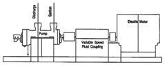
The thermal plant consists of eight units each of which generates 300 Mw of power. Before rehabilitation each unit was serviced by two motor-driven 50% capacity boiler feed pumps and one 10% motor-driven auxiliary boiler feed pump operating in a standby mode. The 10% auxiliary boiler feed pump was replaced by a 50% pump during the rehabilitation program. Each unit is now serviced by three 50% sets; one serves as a backup. A schematic representation of the pump/ motor assembly is shown in Figure 1.
Summary
This two-part article describes the analysis, modal testing, and modification of the drive motor of a boiler feed-pump in a thermal power plant. Axial vibration levels increased in the assembly within a short time after commissioning. Both motor bearing shells had a broad-band resonance in the range from 53 Hz to 70 Hz. In addition, the support plates for both bearings were flexible and did not provide adequate stiffness for the bearing assemblies. The system and the analysis are presented in Part I. Part II deals with modal testing and modifications of the bearing assemblies.
Ontario Hydro has been rehabilitating their thermal power plants. Equipment has either been repaired and upgraded or replaced with new machinery. One new boiler feed pump/ motor assembly was added to two existing assemblies during the rehabilitation program. The new assembly exhibited high levels of axial vibration at the motor bearing assemblies. Vibrations levels were marginally higher than the specification limits during shop testing and commissioning and increased to unacceptable levels within a short time. Diagnostic analysis of the complete pump/motor train indicated that the causes of the high axial vibration were a broad-band resonance in the frequency range from 53 Hz to 70 Hz on both motor bearing shells as well as inadequate axial stiffness from the support plates for the bearing assemblies. The flexibility of the bearing supports resulted in a gradual shift of the broad-band resonance to match the operating speed of the motors.
Base levels of vibration in boiler feed pump/motor assemblies are usually a combination of various phenomena. Causes of high vibration levels include hydraulic effects [[1]; rotor unbalance[2]; operation close to critical speeds [3, 4]; and mechanical and electrical unbalances. Forces that generate high levels of vibration in induction motors have been described [5]. Axial vibrations of the bearing support system of the pump and the drive motors are usually within an acceptable range.
The results of the diagnostic analysis of peculiar incidents of high axial vibrations are presented in Part 1 of this article. The analysis pinpointed the cause as a weak motor bearing assembly with a structural natural frequency that matched the operating speed of the motor. The motor manufacturer agreed with Ontario Hydro that the bearing assemblies had to be
The boiler feed pump is a barrel design with seven-state radial impellers. The allowable working pressure of the pump is 23 Mpa at a temperature of 166°C. The pump is fitted with an oil-lubricated journal bearing at the drive end (DE) and an oil-lubricated journal bearing and a thrust bearing at the nondrive end (NDE). The rotor is coupled to the electric motor through a variable-speed fluid coupling.
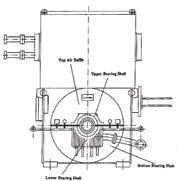
The new motor is a three-phase asynchronous squirrelcage induction motor. It has the following specifications: power, 3,954 kw; voltage, 4,000 V; current, 651 A; and operating speed, 3,577 RPM. Two cross sections are shown in Figure 2. The bottom part of the motor bearing housing is designed as a bearing end-shield half (single piece casting) to which the bearing housing cover plate is bolted. A cover plate (air baffle) was used on the top half to simplify construction, dismantling, and inspection. The bottom half end shield was ribbed to provide stiffness.
The bearing shelf consists of a steel support ring with a metal lining. The middle of the shell is almost in line with
the carrier plate of the bearing end shield. This arrangement reduces deformation and provides more uniform rigidity compared with laterally offset bearing arrangements. The spherical shell seating is particularly suited to absorb high axial and radial forces.
Heavy end caps (see Figure 2) have masses of 90 pounds (NDE cap) and 120 pounds (DE cap). The caps were designed by the manufacturer as covers over the shaft and for mounting proximity probes in two orthogonal directions.
Vibration Specifications
All rotating equipment must satisfy different performance standards including base vibration levels. Levels on the new pump/motor assembly were measured to show conformity with limits specified by Ontario Hydro.
Acceptable vibration limits for the motor and specific measurement procedures are contained in Ontario Hydro’s technical specification for four KV squirrel-cage induction motors [6]. This specification requires that the overall vibration velocity measured at the motor bearings cannot exceed 2.8 mm/second rms (0.11 inch per second rms) in all directions. The motor manufacturer determined the levels at the bearing assemblies (Table 1). The horizontal and vertical vibration levels were within the specified limits. However, the axial vibration levels at the NDE side of the motor were considered marginally acceptable based on ISO Standard 2372 [7]. The motor was accepted for shipment.

Table 1. Uncoupled Vibration Levels of Motor Bearing during Shop Testing. Velocity levels, mm/second, 0-peak.
The pump/motor assembly was also tested after installation in the power plant. The vibration levels were low, and the site supervisors approved the set.
Vibration Levels
Within a short time of commissioning high vibration levels were reported by the maintenance staff. Preliminary measurements showed levels considerably higher than those measured during the shop testes. Levels of 23 mm/second (0.9 IPS) on the bearing shell and 45 mm/second (1.77 IPS) on the top air baffle placed the motor in the range D, which is the most severe operating condition for the motor [7]. The diagnostic procedures used to determine the cause of the high vibration levels are describe in the following section.
Table
NOTE: DE refers to Drive End and NDE refers to Non-Drive End and all measurements are on the bearing shell, unless otherwise noted. Velocity levels are provided in derived peak (rms x 1.414). To convert velocity levels to inches/second, divide by 25.4.
Analysis
NOTE: DE refers to Drive End and NDE refers to Non-Drive End. Velocity levels are provided in derived peak (rms x 1.414). To convert velocity levels to inches/second, divide by 25.4.

Vibration limits were also specified for the pump set. The vibration velocity of the bearing pedestals, all-pass (unfiltered) in the direction of the least radial stiffness, cannot exceed 4.5 mm/seconds rms (0.18 IPS rms) from recirculation flow to 70% rated flow and 2.8 mm/second rms (0.11 IPS rms) from 70% rated flow to 120% rated flow. Shot tests conducted by the manufacturer showed that vibration levels were within the acceptable range (Table 2).
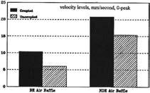
The most important component of a diagnostic method is to collect data following a predefined procedure. Different combinations of data are used to eliminate or focus on possible causes of high vibration levels. Vibration levels (velocity, mm/ second, 0-peak) were measured at various locations around the motor. The measurement program included different load conditions; coupled and uncoupled motor; and with/ without end caps (proximity probe housing). Results of initial measurements are presented in Table 3. The vibration energy had components in both the radial and axial directions and was primarily centered in the 59.6 Hz component (1 x RPM) of the motor.
Table 3. Vibration Levels of the Coupled System after Commissioning. Velocity levels, mm/second, 0-peak.
NOTE: DE refers to Drive End and NDE refers to Non-Drive End and all measurements are on the bearing shell, unless otherwise noted. Velocity levels are provided in derived peak (rms x 1.414). To convert velocity levels to inches/second, divide by 25.4.
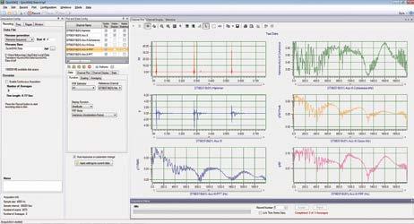
Both axial and radial vibration levels were high, and the ratio of axial vibration to radial vibration was also high. Spectra of axial, horizontal, and radial vibrations measured at the NDE bearing assembly are shown in Figure 3. Similar high vibration levels in both axial and radial directions were also observed on the pump bearings.


A number of mechanisms can produce high vibration at 1x RPM, including hydraulic unbalance, hydraulic instability, mechanical unbalance, internal rub, misalignment of pump/ motor, electrical effects, soft foot, and system resonance. Each mechanism was analyzed.
Visual Inspection I
The interior of the pump was inspected first because of its history. The mechanical seal close to the outboard bearing was found to be rubbing lightly against the rotor. Levels were measured after the seal cartridge was replaced (Figure 4; locations 1 and 2 are on the bottom bearing plate, 1 close to the lube line and 2 away from it). Vibration levels before and after inspection did not differ.
Hydraulic and Mechanical Unbalance

Hydraulic unbalance is caused by uneven hydraulic loading. The uneven loads result form uneven flow patterns and uneven volumes between vanes or liquid passage due to uneven spacing. Hydraulic unbalance is usually represented at the synchronous speed and is superimposed on mechanical unbalance. The vibration response from highly affected by the loading condition. Figure 5 shows that the change in vibration levels with the pump load was negligible and that radial levels were small.


Mechanical unbalance results from deficiencies in the shaft or impellers of rotating equipment. The vibration has a consistent phase along the radial direction and is independent of loading. The high radial vibration measured in the vertical direction at the operating speed was due to the effect of coupling between axial and radial vibrations.
during the assembly procedures. High axial vibrations at operating speed and blade-passing frequency can occur if centering is not maintained. Impeller-to-diffuser geometry was satisfactory. Tolerances were checked during reassembly of the pump to assure that overlap had not occurred.
Visual Inspection II
The interior of the motor was examined after the top cover was removed. Preliminary inspection indicated that the cooling fans located close to the ends were rubbing against the cover. The cover was machined and realigned over the fans. Vibration levels measured in the axial direction did not differ from those shown in Figure 4.
Electrical Effect
Check Electrical Unbalance Soft Foot
Pump/Motor Misalignment
Hydraulic Instability
Hydraulic instability [8-10] is not confined to the pump in which it originates and can affect the entire system or a part of it internal or external to the pump. Hydraulic instability can cause large vibration amplitudes at certain frequencies that can trigger internal and system instabilities. The important vibrations have frequencies at operating speed or bladepassing frequency.
Three factors that can give rise to hydraulic instability are shown in Figure 6. They are gap ‘A’ between shrouds of impeller and diffuser; gap ‘B’ between impeller blade and diffuser vane; and overlap between the shrouds of impeller and diffuser. Defects due to gap ‘A’ and gap ‘B’ are usually identifies as low-frequency vibration or vibration at bladepassing frequency. No components were found in any of the frequency bands. Defects due to overlap between shrouds were avoided by centering the shrouds and checking overlap
Misalignment between pump and motor usually causes high axial vibration. Extreme caution is necessary when the shaft of coupled components are initially aligned. Misalignment can still occur from flexible baseplate designs; loose foundation bolts; piping loads from static, dynamic, or thermal causes; relative thermal expansion between motor and pump; incorrect positioning of motor and pump such that the distance between the ends of the shaft exceeds the flexible limits of the coupling; and failure to use dowels to maintain the established alignment.
Vibration caused by misalignment generally occurs at the operating speed of the pump but can also occur at multiples of operating speed. The measured vibration in the present case was mostly at operating, and misalignment was a primary suspect. The results of vibration levels measured with the pump decoupled from the motor are shown in Figure 7. Axial vibrations at DE and NDE of the motor remained high; it was thus concluded that misalignment was not the cause. The problem was therefore confined to the motor.
Vibration at operating speed can be cause by electrical unbalance resulting from excessive eccentricity of the rotor within the stator winding. The eccentricity uneven magnetic flux distribution around the rotor that results in an unbalanced magnetic pull. High levels of axial vibration can also be generated in the skewed path due to the unbalance. The motor shaft can oscillate axially relative to its magnetic center to produce axial excitation;such a case has been reported [11].
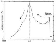
Coast-down tests were carried out by suddenly stopping the motor. The peak axial vibration level as a function of frequency was measured on the NDE bearing (Figure 8). The vibration energy at 59.6 Hz appeared to decrease and then increased to a maximum at 42.5 Hz when the decelerating motor crossed a critical speed of the system. The vibration then continued to decay as the motor slowly came to a stop. If the vibration problem had been primarily an electrical effect, the vibration level at operating speed would have decreased significantly before increasing at the critical speed. The decrease in vibration when the motor was stopped was very small, indicating the existence of a small amount of magnetic pull in the system.
Soft foot is a condition residual unbalance that is magnified by a soft support. The soft food test involved measuring the axial vibration levels when bolts connecting the motor feet to the concrete pedestal were tightened and loosened. Result of the test are given in Figure 9. The change in vibration levels between tight and loose bolts was negligible.
Effect of End Caps
Axial vibration levels were measured on both the NDE and DE bearing assemblies, with and without the NDE end cap. The end cap at the DE bearing was never installed due to assembly problems. Table 4 shows results of measurements at the bearing assemblies. Note that the axial vibration at the NDE was reduced by 50% when the end cap was removed. Additional measurements were taken in which the NDE end cap was lifted with a hydraulic jack. A torque was generated on the NDE bearing housing that provided additional axial stiffness to the bearing support. The magnitude of the axial vibration measured on the DE bearing support decreased substantially when the torque was applied at the NDE bearing (see Table 4). It appeared that the axial vibrations of both bearings were linked.
The tests indicated two possible mechanisms. First, the torque generated by the static weight of the NDE end cap could tilt the bearing support and result in a misaligned hearing assembly. However, the phase information did not support this theory. Second, the extra mass of the end cap and the bearing housing could change the structural resonance frequency of the system of the motor.