Charter High School for Art and Design
Arch 8013_Comprehensive Design Studio
Prof. Robert Z. Shuman
Verena Rezkalla
I have to begin by expresssing my deepest gratitude to Professor Robert Z. Shuman for his invaluable guidance and unwavering support throughout the enriching journey of Comprehensive Architecture Design Studio. His profound expertise, insightful critiques, and constant encouragement have been vital in shaping not only this project but also my architectural perspective as a whole. Professor Shuman’s passion for architecture and commitment to academic excellence have been truly inspiring, encouraging me to engage more deeply with design as a meaningful and transforming discipline. Thank you for your mentorship, for being a constant source of motivation and for your readiness to offer guidance whenever it was most needed.
i. RESEARCH, ANALYSIS & SCHEME
1. Site
2. Precedents
3. Concept, massing & program
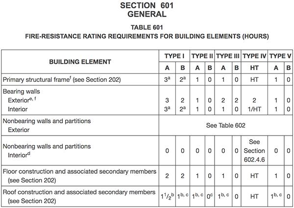
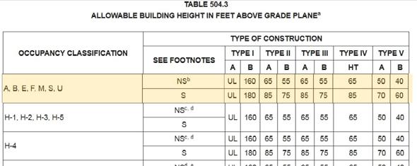
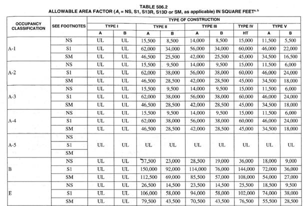
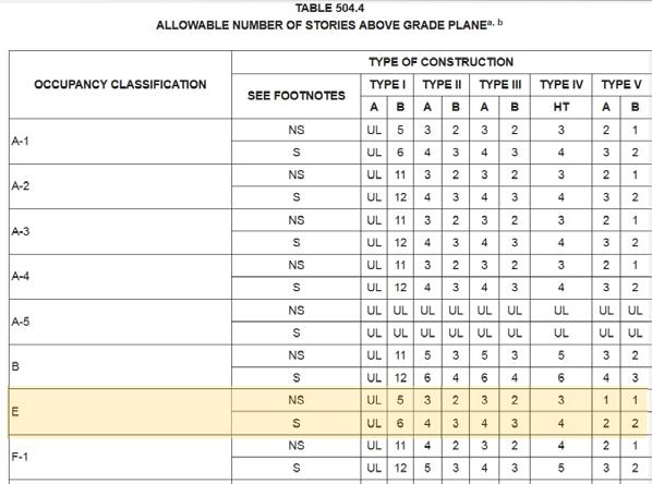
4. Construction type & code compliance
ii. ARCHITECTURAL DRAWINGS
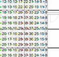
5. Floor Plans, Room Schedules & Areas
6. Site plan
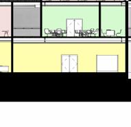
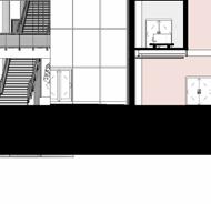
7. Sections & Section perspectives
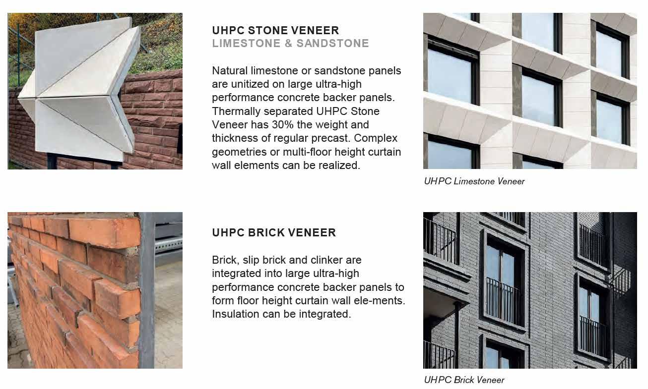
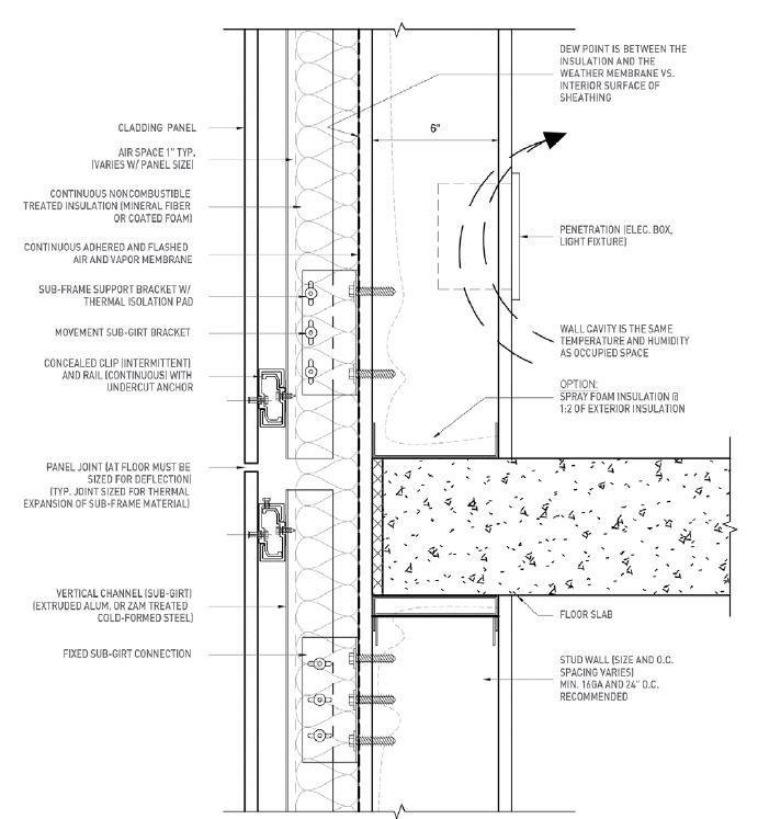
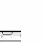
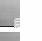
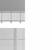
8. Elevations, Facade system & Wall Sections
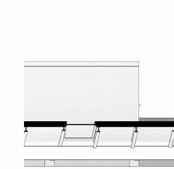
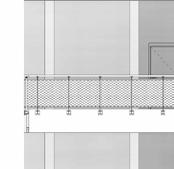
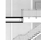
9. Details
10. Renderings & physical model
iii. TECHNICAL DRAWINGS
11. Structure System & Framing plans
12. HVAC Systems
13. Studio Reflected ceiling plan
iv. ENERGY ANALYSIS & SUSTAINABILITY
14. Energy Analysis 15. Sustainable Design
SITE LOCATION
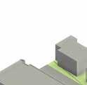
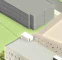
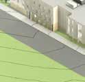
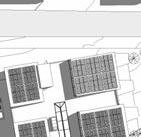
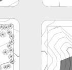
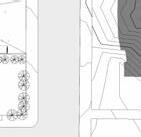
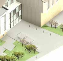
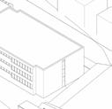
The selected site for the new Charter High School for Architecture and Design (CHAD) is located in the North Central Philadelphia neighborhood, at the intersection of Diamond Street and 13th Street, directly adjacent to the Military Academy and across from Temple University’s Main Campus. The site is primarily zoned RM-1, with CMX-2 zoning at the southwest and southeast corners. It is surrounded predominantly by institutional land use (SP-INS) associated with Temple University, and residential zoning (RSA-5) corresponding to the adjacent rowhouses. This zoning and land-use context played a critical role in informing the placement of programmatic elements, ensuring a sensitive and responsive integration with the surrounding context. Additionally, the transportation map indicates that primary access to the site is from Broad Street, which significantly influenced the design and orientation of the site’s main entrance.


Students lounge spaces in Hokkaido University of Science High School in Japan by TAISEI DESIGN Planners Architects & Engineers.
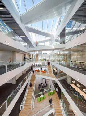
Dynamic attrium, staircase and bridges in the educational center for VUC Syd in Denmark by AART Architects + ZENI Architects
Dynamic and different-level communal spaces in Lumit Art High School in Finland by Lukkaroinen Architects
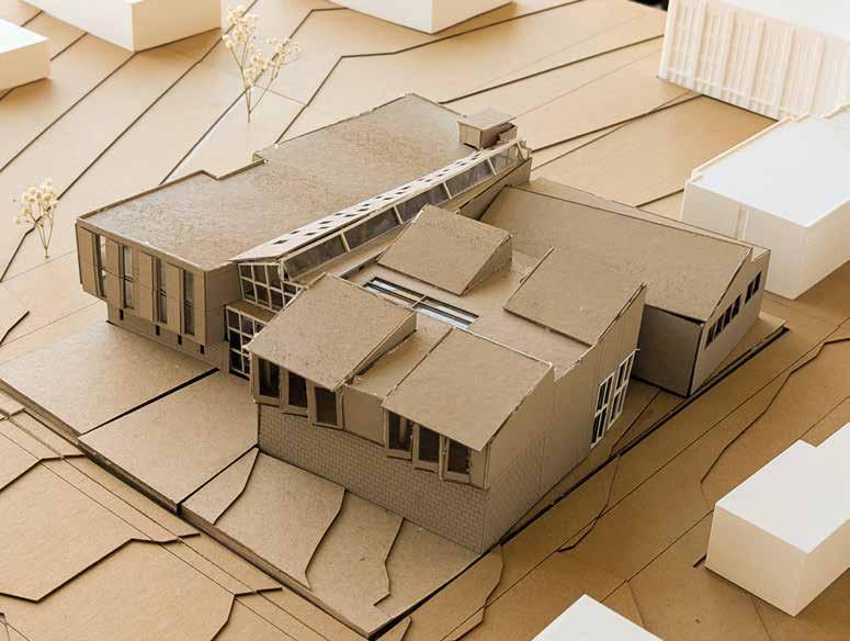
CONCEPT
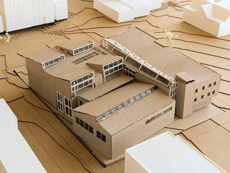
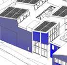
At the heart of this project lies the belief that architecture has the power to shape not only how we move through space, but how we think, feel, and connect. The design is guided by a clear and intentional spatial scheme that distinguishes between large, community-oriented program elements—such as the auditorium, gymnasium, and library—and smaller, day-to-day academic functions. These larger spaces are positioned along the eastern wing, across from the residential rowhouses on 13th Street, addressing the street and inviting interaction with the broader community. In contrast, the more academic and focused spaces—classrooms and service areas—are positioned to the west, forming a quieter, more private wing. At the heart of the building, a monumental atrium serves as a unifying element, weaving the two wings together and crafting a strong architectural and experiential connection between the “big” and the “small.” This atrium is not simply a circulation space—it is a civic heart, a moment of pause and clarity, where the collective energy of the school converges. Through this clear spatial hierarchy, the design resists the fragmentation maze-like experience often found in institutional architecture, fostering a stimulating and uplifting environment that supports the well-being of both students and faculty in their daily routines.


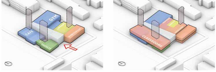

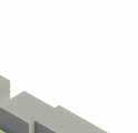
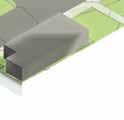
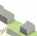
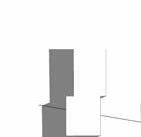
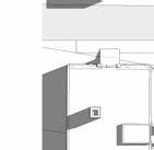
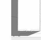
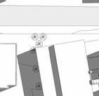
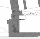
DIAGONAL SLICE TOWARDS BROAD ST. PUSHING IN TO CREATE THE ENTRANCE SMALLER SPACE ON THE LEFT, CONNECTING THEM BY A FUNNEL-SHAPED ATRIUM
OS ON THE THIRD LEVEL
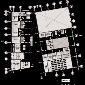
FLOOR PLANS
Art and design Studios
N PARK AVE
13TH ST.
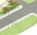
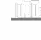
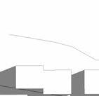
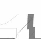
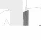
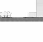
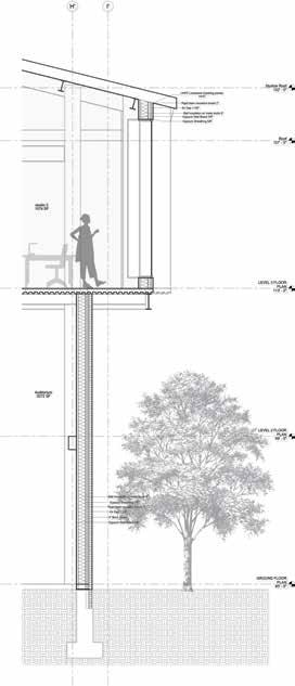
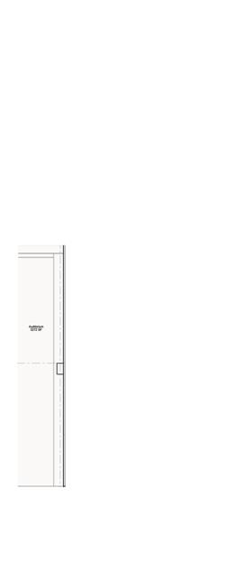
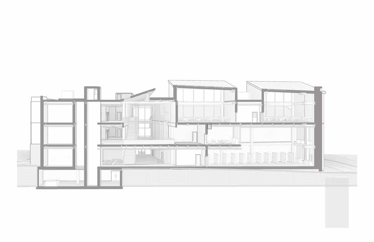
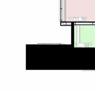
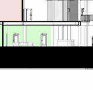
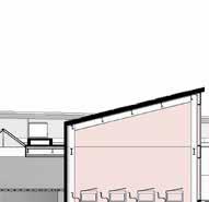
Site Section
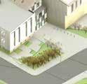
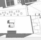
Site Plan
Military Academy
Rowhouses
Tyler
Klein


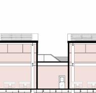

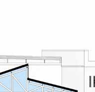


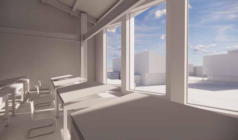
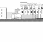
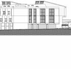
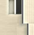
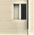
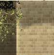
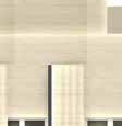
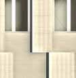
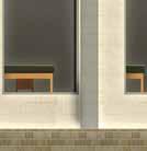
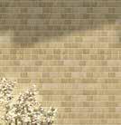
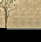
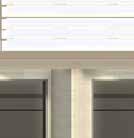
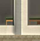
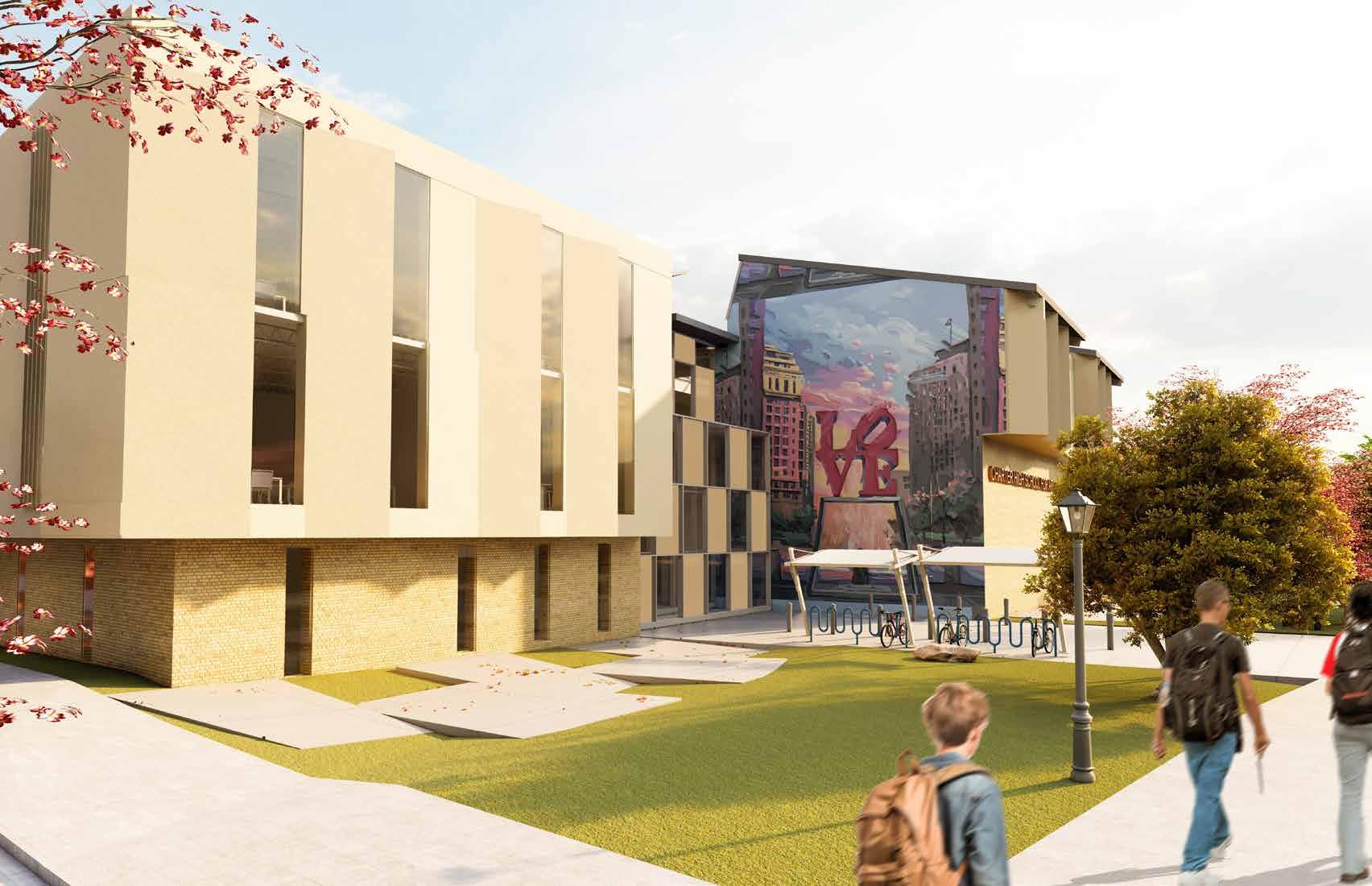
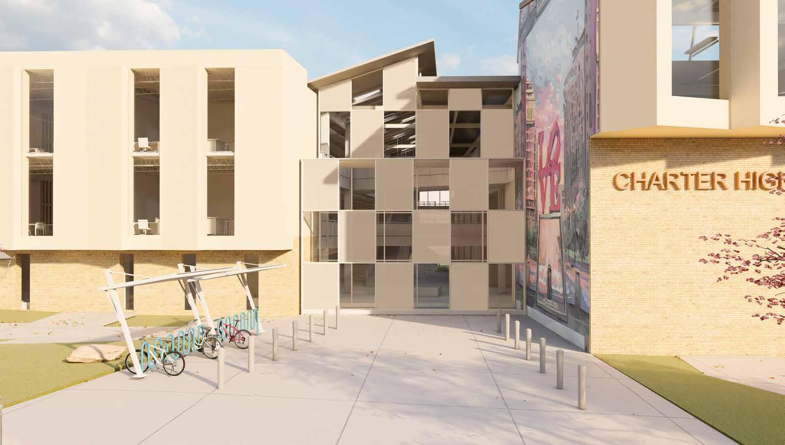
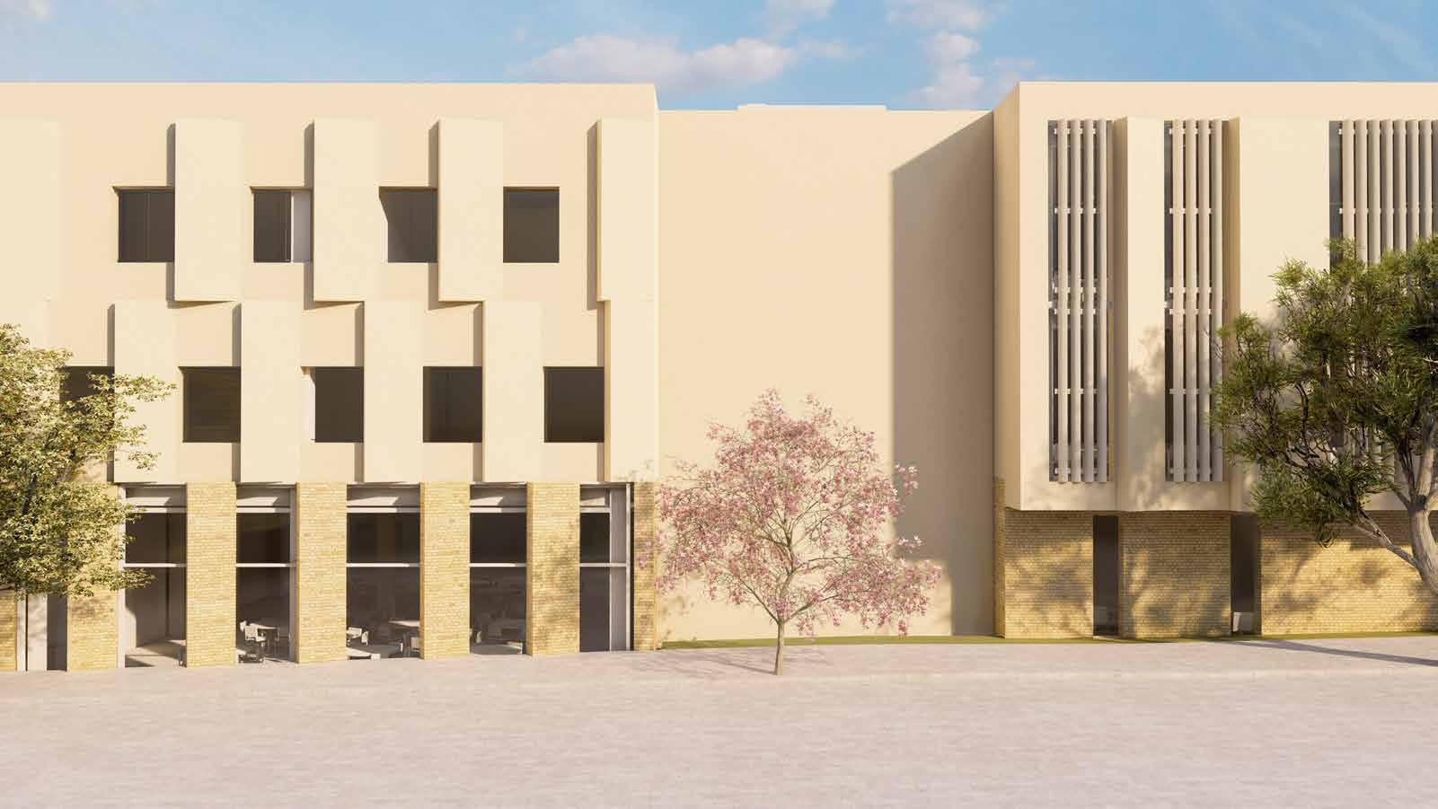
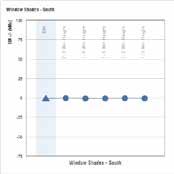
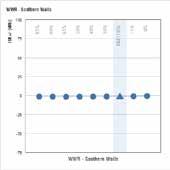
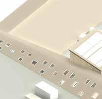
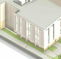
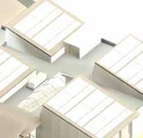
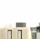
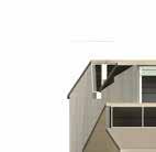
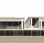
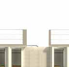
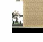
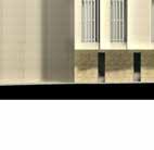
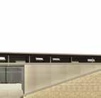
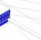
The elevations were thoughtfully designed to express the functions housed within the building while also responding sensitively to both the climate and the surrounding context. The primary façade—the south elevation—features a monumental glazed entrance articulated with a playful checker-board pattern of clear and frosted glass. This composition creates dynamic light patterns within the interior and draws visual emphasis to the entry point. The art and design studios are expressed as four distinct masses, each crowned with sawtooth roofs and two of them oriented with generous south-facing glazing toward Tyler, emphasizing architectural identity and connection. On the west façade, the classroom wing subtly references the small window proportions of the adjacent military academy, reflecting a deliberate approach to contextual and environmental responsiveness. The inward offset of the ground floor in relation to the second and third levels creates a shadow line that clearly articulates the separation of programmatic functions across the building’s vertical hierarchy. Additionally, a low window-to-wall ratio (WWR) was achieved through the strategic and purposeful placement of openings. This approach resulted in an average WWR of 16% across all four façades, as further illustrated in the Energy Analysis section


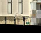
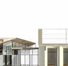


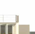


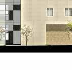
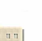


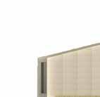


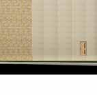


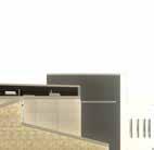


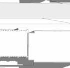
South Elevation - Main Elevation
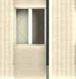
West Elevation
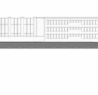
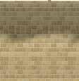
North Elevation
East Elevation
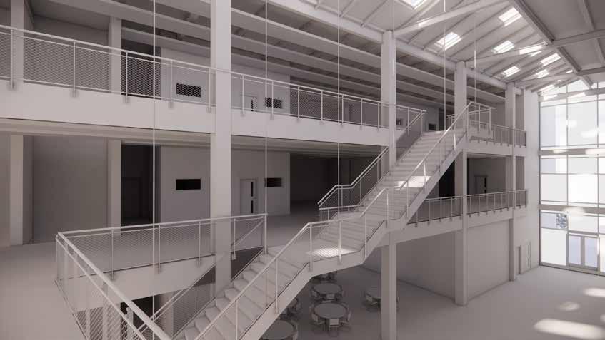
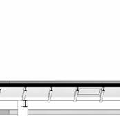
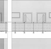
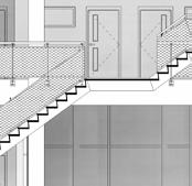
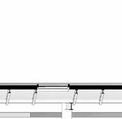
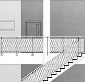
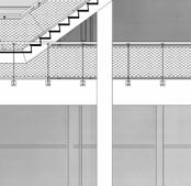
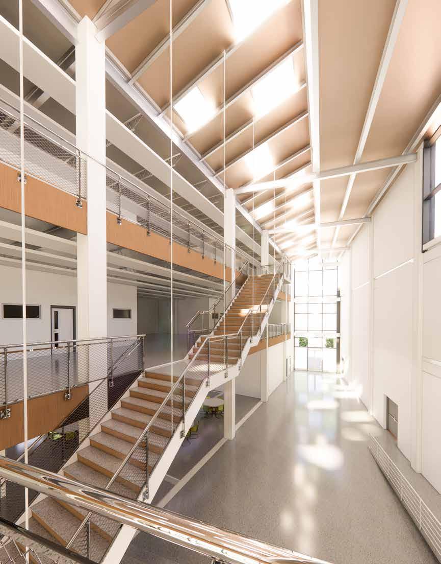
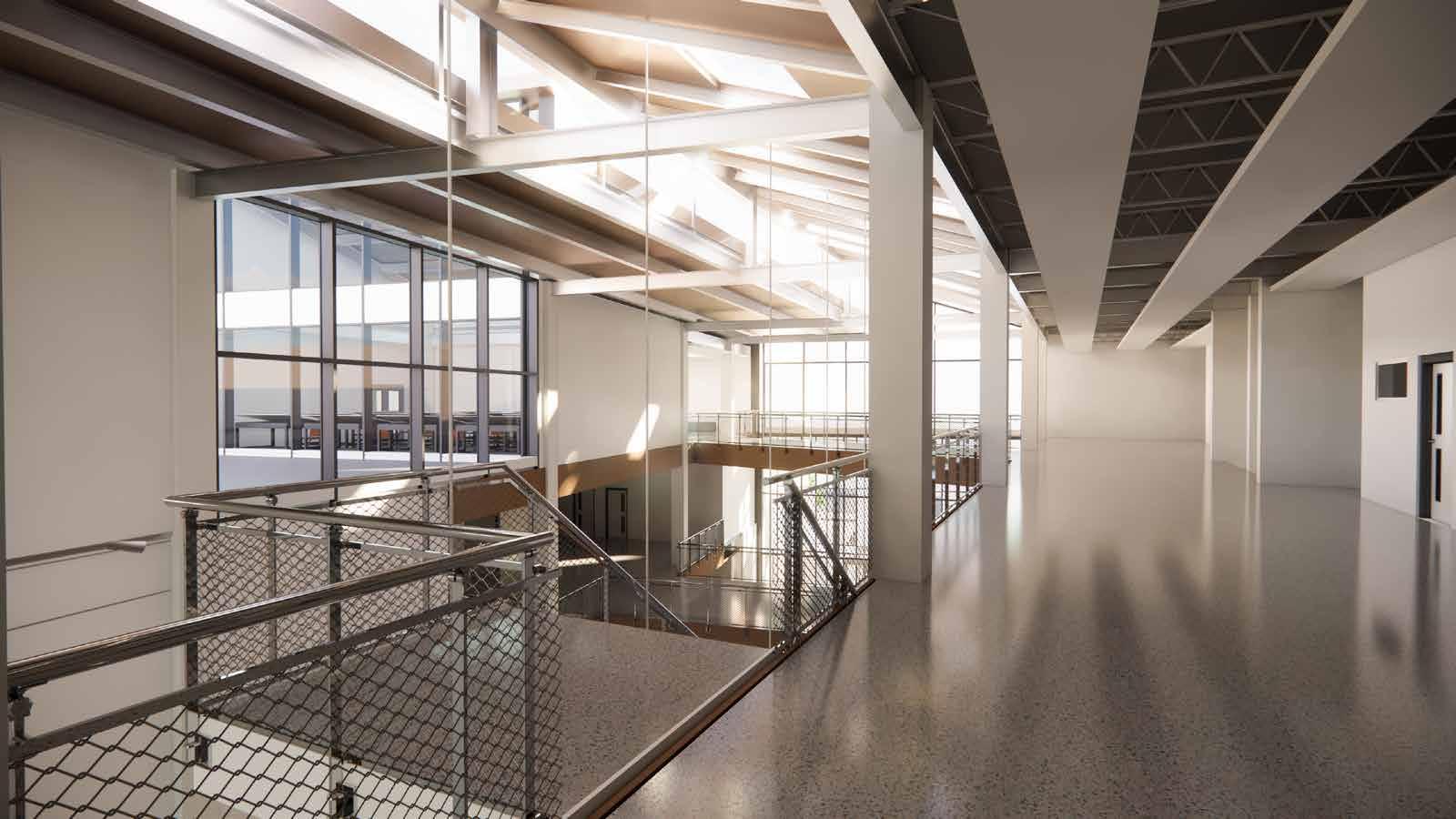
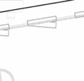
The monumental three-story staircase is designed as a single continuous flight with multiple intermediate landings designed to encourage pause and interaction. Constructed of steel, the staircase is supported by columns and stringers. For additional structural stability, one side of the staircase is suspended from the atrium’s structural beams using tensioned steel rods, creating both a visually striking and functionally efficient design solution.
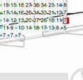
18' - 2 1/2" 5'10 7/8" 7'9 5/32"
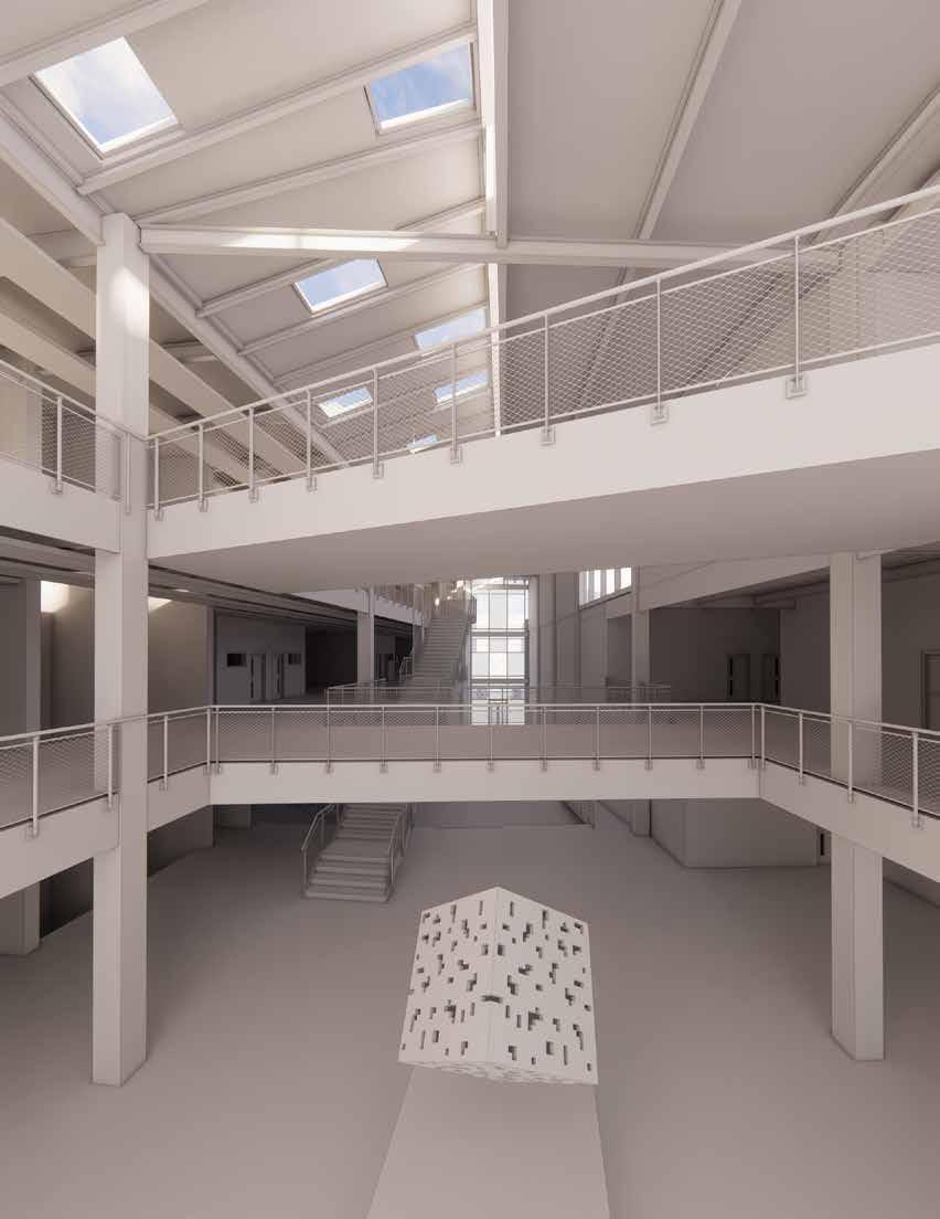
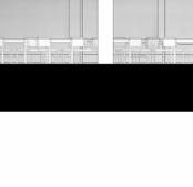
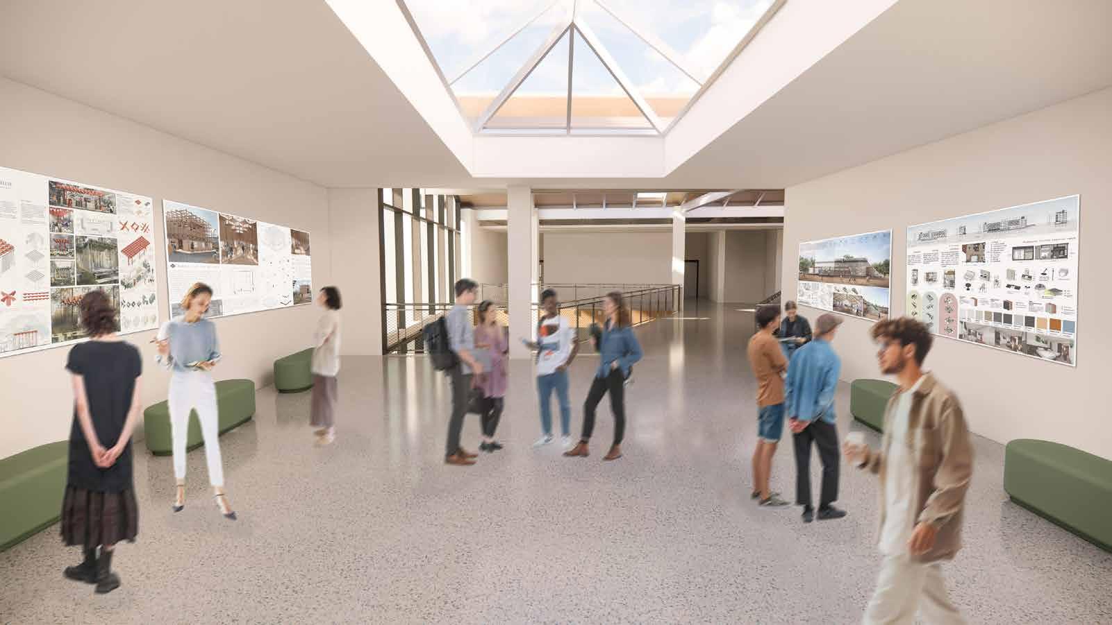
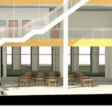
The atrium
Designed as a dynamic and monumental central space, defined by a series of columns, elevated bridges, a suspended staircase, and a playful checkerboard-patterned skylight that crafts a powerful sense of openness and grandeur—reminiscent of the vast central nave of a chapel. From this soaring communal volume, a series of more intimate corridors branch off, leading to classrooms in a manner that echoes the spatial hierarchy of smaller chapel chambers. This spatial organization effectively establishes a strong sense of inward focus and reinforces a clear hierarchy between the “grand” space and the more private, “smaller” zones, creating both visual drama and functional clarity.
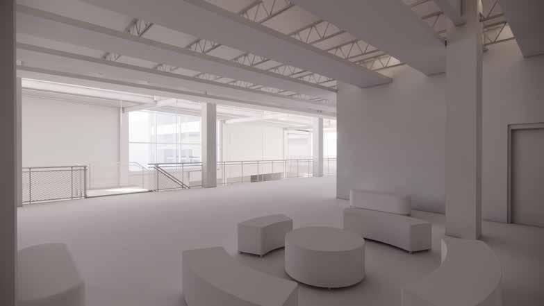
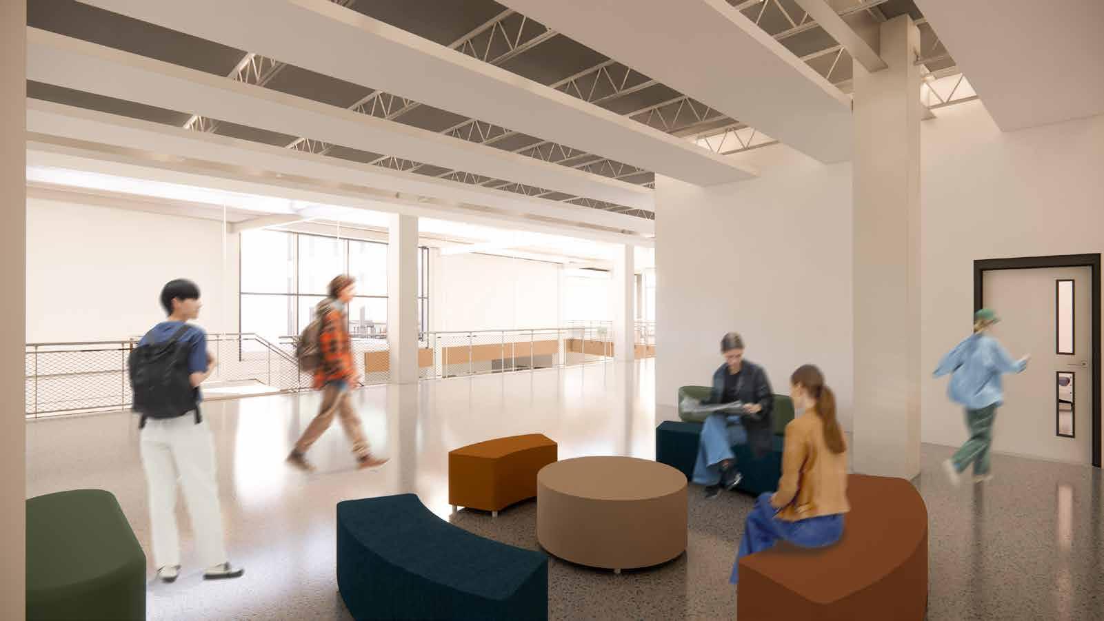
STUDENT LOUNGE SPACES
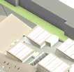
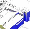
VIEW FROM SE CORNER
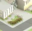
VIEW FROM NE CORNER
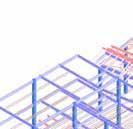
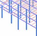
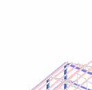
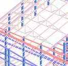
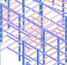
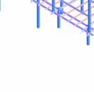
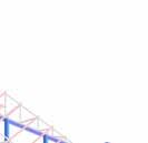
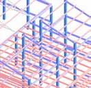
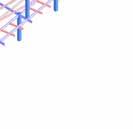
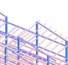
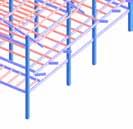
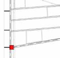
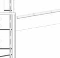
STRUCTURE SYSTEM
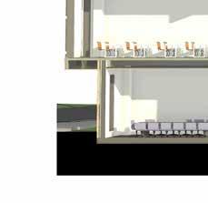
A steel structural system—comprising columns, beams, and metal decking—was proposed to ensure the building’s structural integrity while maximizing spatial efficiency. Due to its lightweight properties and reduced structural depth compared to concrete or timber, steel allowed us to achieve generous clear heights across all programmatic spaces. Steel wide-flange beams were employed in areas where height constraints were not a concern, such as the double-height atrium, library, and studios. In classroom areas, bar joists were used to accommodate HVAC ductwork within their openings, thereby minimizing the overall ceiling plenum depth. Additionally, a series of roof trusses, spaced at 21 feet on center, were implemented to span and support the gymnasium roof structure.
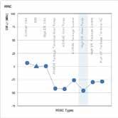
HVAC SYSTEM
A highly efficient geothermal heat pump system was proposed to meet the HVAC demands of the project. This system operates by circulating water from heat pumps to a central condenser/evaporator unit, where the water is either heated or cooled based on the building’s thermal requirements. The conditioned water is then distributed through underground piping, enabling radiant floor heating in large common spaces and supplying both active and passive chilled beams for efficient cooling. Additionally, the system transfers hot or chilled water to a rooftop air handling unit (AHU), which conditions the air and delivers it to the atrium through side-mounted supply and return diffusers. For the studios, passive chilled beams were proposed as a state-of-the-art solution, paired with a Dedicated Outdoor Air System (DOAS) to provide separate fresh air ventilation and enhance indoor air quality.
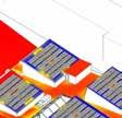
LEVEL 3 FRAMING PLAN
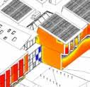
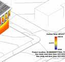
SOLAR INSOLATION
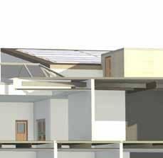
To achieve a high-performance, energy-efficient design, a series of environmental analyses were conducted to evaluate how variables such as solar exposure, daylight and electrical lighting influence the building’s energy consumption and spatial quality. Solar insolation was analysed for both the walls and roof surfaces during different times of the day in the summer and winter solstices to understand seasonal variations in heat gain and daylighting potential. In response, vertical shading fins were strategically placed on the west façade to mitigate glare and reduce solar heat gain during peak summer conditions. Thermo-chromic glazing was integrated into the southern-facing windows of the science classrooms and the monumental studio windows, allowing occupants to easily control the transition of glass from clear to frosted as needed for thermal and visual comfort. Additionally, roof solar exposure analysis validated our decision to tilt the roofs southward for optimal solar energy harvesting, while integrating north-facing clerestories to maximize diffuse daylight and reduce reliance on artificial lighting.


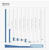
INSIGHT ENERGY ANALYSIS
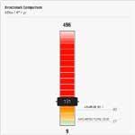
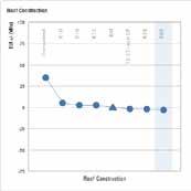
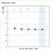
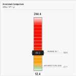
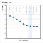
This analysis was conducted to gain a comprehensive understanding of how key design variables—such as window-to-wall ratio (WWR), roof and wall assemblies, HVAC systems, and infiltration rates—impact the building’s overall energy consumption. The model was initially calibrated to comply with ASHRAE 90.1 energy performance standards and subsequently optimized to align with the more intensive energy targets set by Architecture 2030.
MEETING ASHRAE 90.1
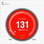
We retained initial design key elements in our revised design that contributed to the building’s low energy consumption. These included wall and roof assemblies with R-values of 26 and 60, respectively, as well as maintaining our initial approach of a strategically low Window-to-Wall Ratio on all four facades, extending the walls to act as vertical louvers on west facade and utilizing sawtooth roofs to capture daylight. The most significant change involved upgrading to triple pane Low-E along with our low WWR. Shading had a negligible effect on improving the energy rating. Ultimately, our design successfully met the ASHRAE 90.1 standards, achieving an energy consumption rating of 89.3 KBtu/ft²/yr.
MEETING ARCH 2030
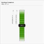
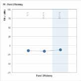
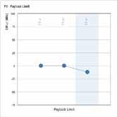
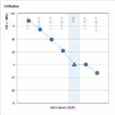
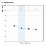
To meet the Architecture 2030 energy consumption target, we did some adjustments that were mainly concerned with infiltration, HVAC system and PV cells. We picked the highly efficient heat pump as the HVAC system which played a critical role in reducing energy usage. To achieve a highly airtight envelope, we initially selected an infiltration rate of 0.5 ACH which helped reduce energy consumption to 39.4 KBtu/ft²/yr. . Additionally, measures such as optimized daylighting, occupancy controls, lighting efficiency, and plug load management further lowered energy consumption. Ultimately, we were able to achieve the Architecture 2030 goal, reaching an energy consumption rating of 26.3 KBtu/ft²/yr by incorporating high-efficiency photovoltaic (PV) cells to cover 60% of the roof area with an efficiency of 20.4%.
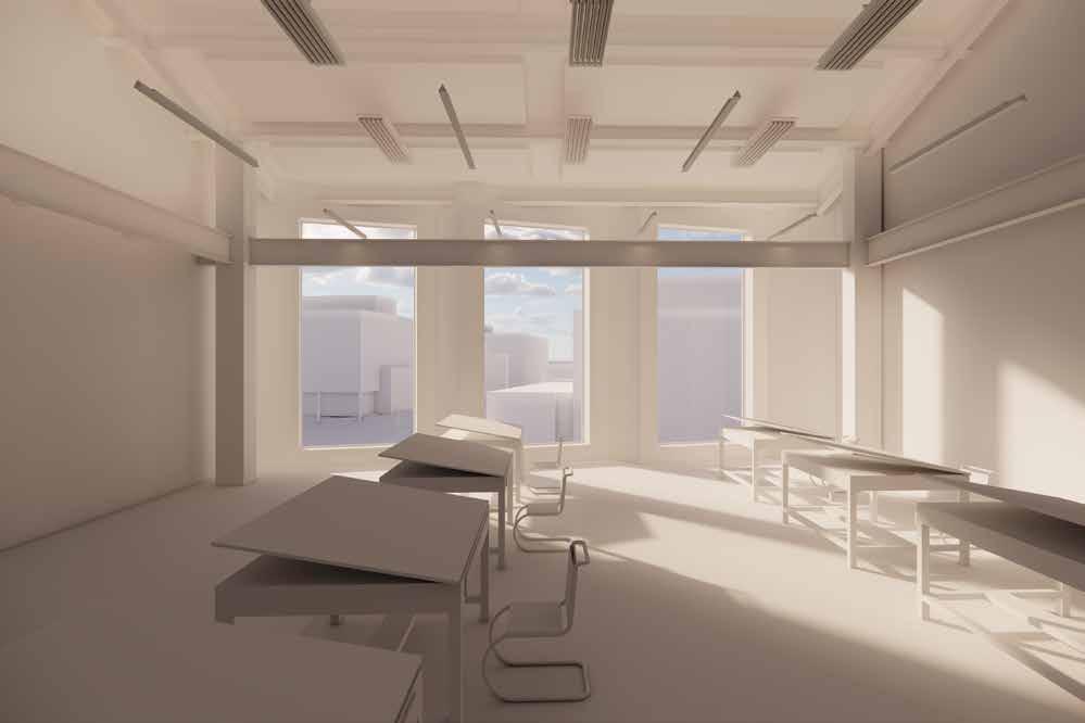
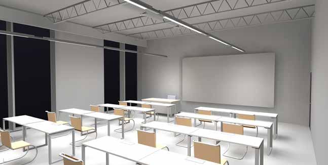
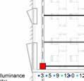
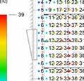
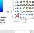
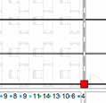
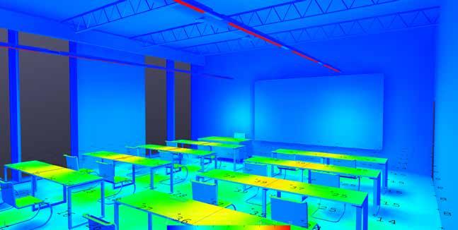
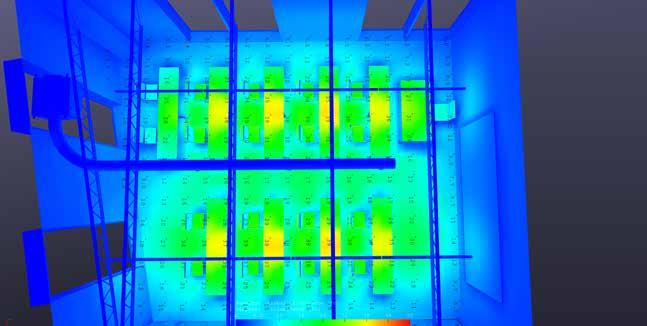
ELECTRICAL LIGHTING DESIGN
We used ElumTools software to perform a electrical lighting analysis for the science classroom. Our goal was to ensure that the proposed lighting system would meet the programmatic needs of a science classroom, which demands consistent, bright, and evenly distributed light for student safety and visual comfort during lab work and instruction. Moreover, the fixtures complemented our architectural intent to create an industrial-style learning environment with exposed structural elements and mechanical ductwork as key features of the design.
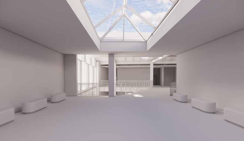
Checker-board patterned skylight over the attrium for playful light
Blue roof for stormwater retention
Angled panels to provide shade for western windows
Sawtooth Roofs for Solar energy collection and daylighting
High Efficiency PV Cells
Rain garden for stormwater run-off infiltration
Angled windows and therno-chromic glass
DAYLIGHT AND SUSTAINABLE STRATEGIES
Vertical fins