

Frontline Dryer Daily Maintenance
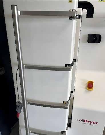
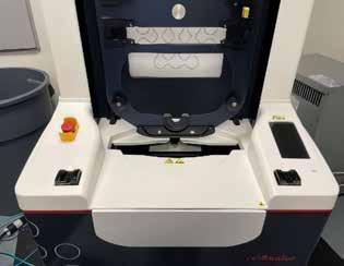
1. Open the enclosure door of the Dryer.
2. Spray a 70% isopropyl alcohol solution or a 10% bleach solution onto a lint-free wipe.
3. With the wipe, clean the Dryer interior and exterior. Ensure cleaning of the following areas:
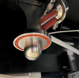
Peristaltic pump and surrounding area
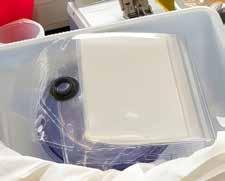
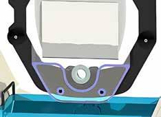
4. Inspect the entirety of the gasket. Ensure the gasket is undamaged and seated properly within the groove.
nozzle *DON’T ATTEMPT WHILE HOT*
PDC air exhaust port
Enclosure inlet and exhaust air ports
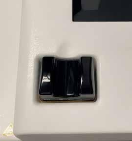
Enclosure door handle
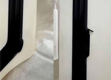
Dislodged locations Damaged location
*Note: An improperly seated or damaged gasket can cause enclosure leaks and/or enclosure pressurizing issues. These will prevent the integrity checks from completing and the spray-drying run from beginning.
UI and surrounding area
Enclosure door key
Drying
Frontline Sealer Daily Maintenance
1. Spray a 70% isopropyl alcohol solution or a 10% bleach solution onto a lint-free wipe.
2. With the wipe, clean the Sealer exterior. Ensure cleaning of the following areas:
3. Press the CLEAN button on the STANDBY UI screen. This will unlock and open the door.
4. With the wipe, clean the Sealer interior. Ensure cleaning of the following areas:
Inside face of sealing jaws (heater band cover tape) and separating jaws (separate wire cover tape).
*Note: Will need to slide out seal and separate module to access jaws.
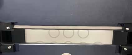
Air extraction gasket
Sealing Jaws
Separating Jaws
Frontline Sealer Daily Maintenance
5. Visually inspect the heater band and separate wire cover tape for any burn marks, scratches, tears, and or deep-set creases. If there is any damage, contact Velico Medical (support@veli.co) to schedule maintenance.
6. When cleaning is complete, slide the sealand-separate modules back into place behind the frame and are returned to the vertical position. Drawers are locked into the correct position when tugging on the drawer yields no movement.
7. Close the door firmly to properly engage the door lock. Errors can occur if the door is not fully closed or if the door lock has not been fully engaged. The UI provides warnings of shuttle motion and prompts operator to hold safety buttons.
Step 1: Pretreatment
1. Inspect the PPC for damage.
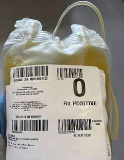
2. Ensure plasma has a sterile connection compatible pigtail length, a minimum of 6 inches (15 cm) is recommended.
3. Apply a hemostat or clamp to the PPC tubing.
4. Connect the PPC to the plasma unit by SCD. Do not exceed 20 in (51 cm) of tubing length between them post-SCD.

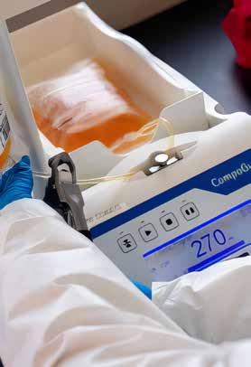
5. Transfer a target volume of 275 mL of plasma (range of 265-285 mL) into the PPC using a Fresenius Kabi CompoGuard blood collection monitor or manually using a scale.
6. Seal and separate the plasma unit from the PPC when the target volume is transferred.
7. Inspect the PDC lid/tray and the PDC for damage. Clamp the white clamp on the PDC plasma line.
8. Connect the PDC to the PPC unit by SCD.

9. Confirm tubing length from end of opaque section of PDC plasma line to PPC is approximately 10-16 in (25-41 cm).
*Note: Measurement is from end of opaque section closest to PDC plenum to point of PPC connection.
White clamp on plasma line
Step 2: Spray Drying
1. WARNING: If the Clean Dry Air (CDA) system dewpoint is warmer than -40°C, do not conduct drying operations. If it is not capable of maintaining the dewpoint at or below -40°C, notify Velico Medical and the CDA system manufacturer for guidance and service.
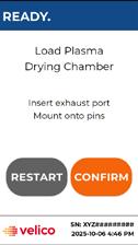
2. Verify user interface (UI) shows READY. If not, then tap WAKE button. Do not proceed to Step 3 until the Dryer completes self-checks and the UI shows READY.


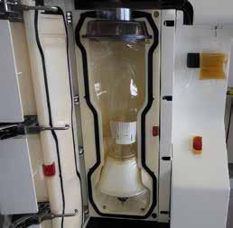
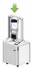
3. Open Dryer enclosure door and hang pretreated plasma unit on the plasma scale.
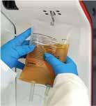
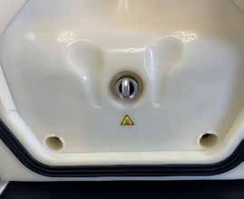
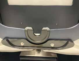
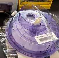
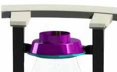
4. Place PDC purple plenum into the enclosure. The plenum fits in one way.
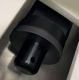
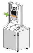
5. Connect exhaust of the PDC to the exhaust port of the Dryer. Ensure the connection is fully seated.
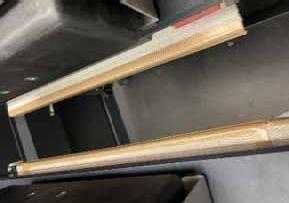
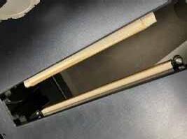
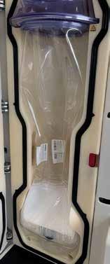
6. Tuck PDC spike ports into the enclosure recess. Ensure the PDC is curved inward into the enclosure cavity. Tuck the corners and edges of the PDC fully into the enclosure cavity.
Recess for PDC spike ports
Exhaust port connection
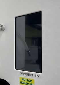
7. Feed PDC aerosol tubing through the retention slot and attach the aerosol filter to the aerosol line connection. Ensure the connection is flush and secure.
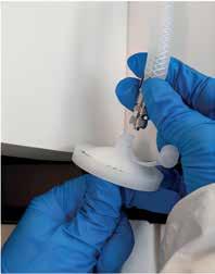
Aerosol filter connection
8. Open the peristaltic pump latch and feed the opaque section of the PDC plasma line through the peristaltic pump and up through the retention slot.
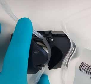
9. Close pump latch once tubing is routed.
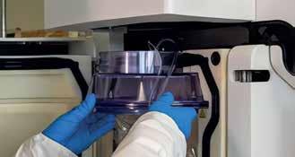
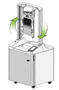
10. Ensure the PDC is not pinched and close the Dryer door.
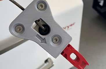
11. Insert manual door lock key (lower left side of the dryer).

Final Setup Door Open and Closing
12. Follow prompt on user interface, “Unclamp Plasma Line”. Pinch open the SCD connection, open the white clamp of the plasma line, and then press CONFIRM.
PDC plenum
VS.
Step 2: Spray Drying Common
13. When the spray drying is complete, remove the PPC from the Dryer scale hook if it was not sealed and separated.
Error Codes
NOTE: Velico recommends not to wait more than 15 minutes between the end of the drying run and the start of seal-and-separation process. The PDC stiffens when it cools down, making it more difficult to load the PDC into the Frontline Sealer. Keeping the Enclosure closed after spray drying will help keep the PDC warm.
14. Carry the PDC and PPC to the tube sealer.
15. Using a tube sealer, seal and separate the PDC from the PPC as close to the PDC cap as possible.
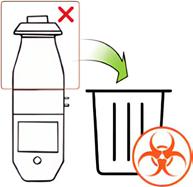
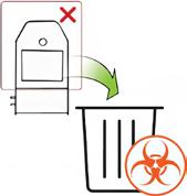
16. Discard the PPC in accordance with facility biohazard policy.
Aerosol Line Disconnected Mass Disturbance Detected
Aerosol Pressure too High
Door Not Sealed
Door Not Sealed
PDC clamp or hemostat clamp engaged on plasma line tubing. Kink/obstruction in plasma line.
Aerosol line disconnected or improperly connected.
PPC disturbed on plasma scale.
Aerosol line pinched or clamped.
Exhaust port not seated or Dryer gasket misalignment.
Dryer gasket misalignment/possible damage.
Step 3: Seal-and-Separate
1. Press Wake on the Frontline Sealer. Complete homing if required.
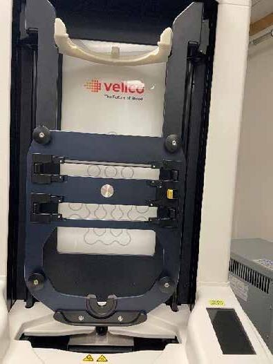
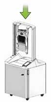
2. Load the purple plenum of the PDC onto the shuttle in the down position.
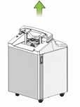
3. Press CONFIRM and wait for the shuttle to rise.

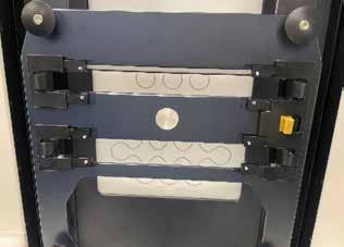
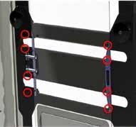
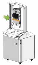
4. Attach the exhaust port (1) and 2 lower grommets (2).
5. Attach the 8 upper grommets.
6. Press CONFIRM and hold finger safety buttons.
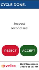
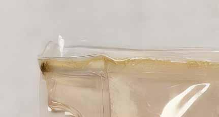
7. Inspect seal #1. If acceptable press ACCEPT. If there is an incomplete seal and/or ODP powder is visible on the outside of the seal, contact Velico before continuing. If there is a question about the seal, contact Velico. (See reverse side for examples).

8. Dispose of upper section and rotate the shuttle.
9. Press CONFIRM and hold finger safety buttons.
10. Inspect Seal #2. See Step 7 for details.
11. Remove the final ODP unit.
12. Dispose of lower portion and rotate the shuttle.
13. Press CONFIRM after rotation and hold the finger safety buttons to lower the shuttle back to Load PDC position.
Step 3: Seal-and-Separate
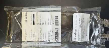
Acceptable Welds = Press ACCEPT
Typical welds in ODP Unit
Complete seals have a roughly uniform width along their length, do not show signs of incomplete melting where the seal is formed, do not intersect with any labels, and do not have any exposed plasma showing.
Partially cut welds are acceptable if the seal is complete and they can be separated by running a finger through the weld.
Common Error Codes
7011
7012
7013
Workflow Shuttle Not Rotated
Workflow Shuttle Not Extended
Workflow Vacuum Target Timeout
Unacceptable Welds (Operator Error) = Press REJECT
Loading the PDC into the Sealer without attaching the 2 grommets and 8 small pins will result in the seals in the incorrect location.
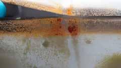
Unacceptable Welds (Sealer Failure) = Press REJECT
Burned (black or green) seals, incomplete seals, or exposed plasma are not typical. Contact Velico Medical (support@veli.co) to schedule maintenance.
Example of burned discolored seal:
The shuttle is not in the correct orientation. The operator forgot to rotate the shuttle.
The shuttle is not in the correct orientation. The operator forgot to extend the shuttle.
Exhaust port seated incorrectly. Obstruction/debris on air extraction nozzle.
Step 4: Storage
1. Weigh and record weight on the ODP unit.
a. Weight ≥ 48g
b. If weight < 48g, discard
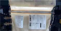
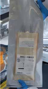
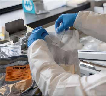
2. Place the ODP unit into the overwrap pouch making sure that the label on the ODP unit is visible through the clear side of the pouch and the spike ports are facing up.
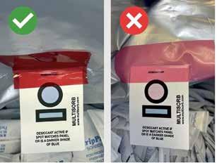
3. Open the desiccant pack and check the moisture indicator.
a. If it is blue: pull one desiccant and immediately close the outer desiccant package to maintain shelf life.
b. If pink, discard the bag of desiccants and get a new one.
4. Place the desiccant between the ODP unit and the foil side of the overwrap pouch so the ODP unit label is not blocked from view.
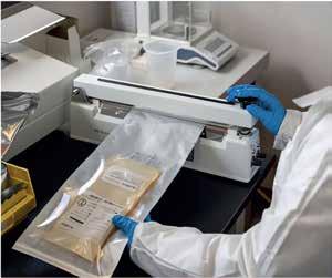
5. Place the overwrap pouch across the sealing band of the heat sealer ensuring that:
a. The sealing band is between the edge of the pouch and the first tear notch.
b. The pouch is not wrinkled.
6. Verify impulse settings: Heat dial = 6 Cool dial = 1
7. Close the welding arm. Wait for welding arm to pop up.
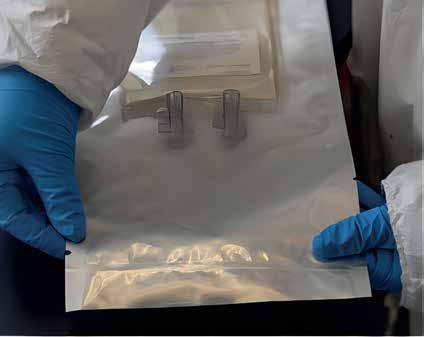
8. Inspect the seal. Pull gently to confirm the weld does not open.
Acceptable Seal Criteria:
- No gaps, or unsealed areas through the width of the seal
- No discoloration
- Note: Wrinkles allowed
Unacceptable Seal Criteria:
- A seal with gaps or unsealed area running through the weld
- A seal that can be pulled open with gentle force
NOTE: It the seal is unacceptable, open the pouch, retrieve the ODP unit and start at step 2 again.
9. Store the sealed package at refrigeration (1-6°C) up to 24 months or at 1-24°C up to 6 months.