K Range
High Torque Electric Valve Actuators
Redefining Flow Control
Rotork is the global market leader in valve automation and flow control. Our products and services are helping organisations around the world to improve efficiency, assure safety and protect the environment.

We strive always for technical excellence, innovation and the highest quality standards in everything we do. As a result, our people and products remain at the forefront of flow control technology.
Uncompromising reliability is a feature of our entire product range, from our flagship electric actuator range through to our pneumatic, hydraulic and electro-hydraulic actuators, as well as instruments, gearboxes and valve accessories.
Rotork is committed to providing first class support to each client throughout the whole life of their plant, from initial site surveys to installation, maintenance, audits and repair. From our network of national and international offices, our engineers work around the clock to maintain our position of trust.
Rotork. Redefining flow control.
2
Contents Section Page K Range Actuator 3 K Range High Torque Features 4 Enclosure Options 5 Drive Options 6 K Range Performance Summary 7 Actuator Motors 8 Wiring Diagram 9 Dimensional Drawings 10
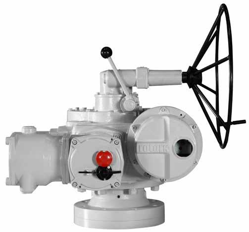
K Range Actuator
With the K Range high torque actuator, Rotork is now able to offer all the proven design advantages of its established ranges at higher torque values than have previously been possible. Available in three models, K4000, K5500 and K7000, these actuators offer torque ratings of up to 7000 Nm and thrust ratings of up to 1115 kN.
Standard K Range high torque features include:
• Double-sealing against the environment, protecting electrical integrity at all times
• Standard wiring diagrams for any valve type
• Thrust or non-thrust mounting flange dimensions to International (ISO) valve standards
• Advanced counter switch mechanism featuring combined torque position limit switches at each end of travel
• Integral starter and control circuit option (Rotork Syncropak)
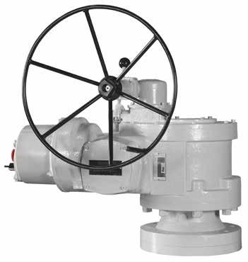

• Three base options for each size of actuator
• Watertight enclosures
3 Redefining Flow Control
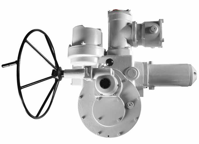
K Range High Torque Features
Syncroset
Syncroset actuators incorporate the motor and limit and torque switches only. This minimizes the electrical equipment at the valve location and is therefore particularly suitable for locations where access is difficult or where excessive vibration may be experienced. However the reversing starter must be separately specified, purchased, installed and tested by the customer and the valve control system is therefore incomplete until wired in the field.
Features
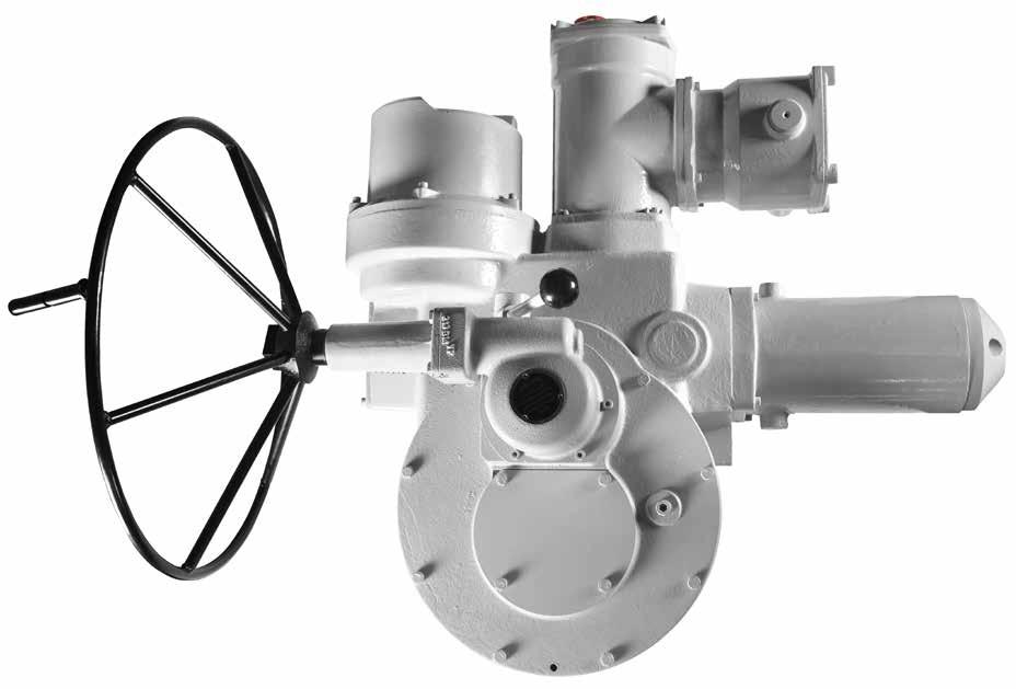
1. Low ratio worm / wormwheel gear combined with final spur reduction gear offering a combined drive efficiency above that of conventional worm reduction designs. The gearcase is oil filled for normal operation in a temperature range of -30 to +70 oC.
2. Separate thrust bases providing increased stem acceptance and thrust if required. Base and flange dimensions to ISO standards.
3. Very advanced all metal counter switch mechanism featuring combined torque and position switch with torque switch latch which prevents valve hammering throughout travel with non-self-locking gears. Switch mechanism is quickly and easily set using only a conventional screwdriver. As with other Rotork designs, the reaction force on the wormshaft, in direct proportion to the output torque is used to trip the 'Open' and 'Close' adjustable torque switches.
4. Built-in squirrel cage motor with winding thermostat, specially designed for valve operation and combining low inertia with high torque. Class F insulation as standard.
5. Hammerblow backlash feature permitting motor to gain full speed before unsticking tight stem nuts, etc.
6. Hand/auto selector lever insures positive engagement of handwheel drive. Power drive automatically restored by motor start unless lever padlocked to prevent it. Generously proportioned wormdrive handwheel provided as standard operating through hammerblow mechanism. The side handwheel ratio is 90:1 giving a mechanical advantage of 33:1.
7. High output speeds at high torque enable large valves to be operated quickly and permit favorable top mounted actuator configuration.
Syncropak or Syncroset?
Any motorised valve requires a reversing contactor starter to switch the three phase motor in response to control signals. This may be separately installed or incorporated in the actuator. Rotork Syncroset actuators require separate starter facilities. Rotork Syncropak actuators contain their own starter and control equipment in a factory sealed and tested package.
Syncropak
Rotork Syncropak actuators incorporate the starter and local controls with considerable economy in site wiring as shown. This arrangement also enables the essential elements of the valve control system to be factory wired and tested and sealed by Rotork Quality Control. Because Syncropak incorporates everything required for operation from a three phase supply, it can be tested on local control by the valvemaker and site contractor with undivided contractual responsibility by Rotork for reliable operation. Syncropak options increase economy and add system reliability by providing a high degree of fault monitoring. Interposing relays enable light current cable to be used for distant remote control and indication. See publication RCIE - 34 for details.
Note: 'K' Range high torque actuators are manufactured with the same wiring diagram options as the Rotork 'K' Range product. In addition, the 'K' Range high torque counter switch mechanism can accept both extra end position and mid position switches.
4
Three phase power supply Remote control indication and interlocks Reversing contactor starter Auxilary limit switches Motor and thermostat Travel limit and torque switches Local Controls
Three phase power supply Remote control indication and interlocks Reversing contactor starter Local Controls Auxilary limit switches Motor and thermostat Travel limit and torque switches
3 2 4 6 1
Enclosure Options
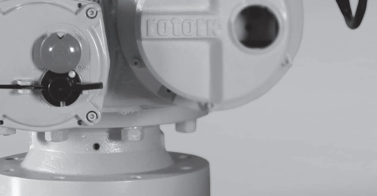
Enclosure options
All 'K' Range high torque actuators are o-ring sealed from the environment and the exclusive Rotork 'double-sealed' feature means that the terminal compartment is separately sealed from the rest of the enclosure to insure that the actuator is permanently protected even during long periods of on-site wiring when the terminal cover is removed.
5 Redefining Flow Control
`O' ring
`O' ring
Drive Options
Drive Options
Three basic output drive column assemblies are available as standard on all sizes of ‘K’ Range high torque actuators.
Dimensions shown below are to International (ISO) dimensions.
F35E
The F35E is the basic torque only form. The center column is terminated with a Type 'E' bore diameter and keyway suitable for attachment to valve makers' gearbox, etc.
F40A
The F40A is a larger version of the F35AL separate base which provides enlarged stem acceptance and maximum thrust rating.
The F35AL is a separate thrust base which is added to the standard gearcase and which contains its own sealed thrust bearing and aluminum bronze drive bush. This feature maintains the maximum rising stem acceptance available through the actuator center column which in this form is simply fitted with a pair of male dogs which engage with the drive bush.
* Note: Optional Flange Type 3 & Type 4 with the following dimensions can be offered
Type 3 : 8 x M24 x 216 spigot dia x 356 PCD x 415 OD
Type 4 : 8 x M30 x 230 spigot dia x 406 PCD x 476 OD
6
5 45 M30 173 79 205 5 M36 5 260 55 40 Pilot bore 224 8 holes drilled thro' equi.spaced 8 holes drilled thro' equi.spaced 8 Holes drilled and tapped M30 equi. spaced 415 356 PCD 260 82 415 356 PCD 260 114 34 50 476 406 PCD 300 127 40
F35AL
5 45 M30 173 79 205 5 M36 5 260 55 40 Pilot bore 224 8 holes drilled thro' equi.spaced 8 holes drilled thro' equi.spaced 8 Holes drilled and tapped M30 equi. spaced 415 356 PCD 260 82 415 356 PCD 260 114 34 50 406 PCD 300 127 40
173 79 205 5 M36 5 260 55 40 Pilot bore 224 8 holes drilled thro' equi.spaced 8 holes drilled thro' equi.spaced 415 356 PCD 260 114 34 50 476 406 PCD 300 127 40
K Range Performance Summary
Performance Data
Stall torque is 1.2-1.6 of rated torque. Limit switch turns range for all sizes is 5-1250 output turns.
Note: For other power supply options refer to Rotork.
Redefining Flow Control
7
Actuator Size Spindle acceptance Max. Thrust (kN) Rated Torque (Nm) Rising (mm) Non-rising (mm) K4000 F35E - 82 - 4,000 K4000 F35AL 110 95 446 4,000 K4000 F40A 125 105 1,115 4,000 K5500 F35E - 82 - 5,500 K5500 F35AL 110 95 446 5,500 K5500 F40A 125 105 1,115 5,500 K7000 F35E - 82 - 7,000 K7000 F35AL 110 95 446 7,000 K7000 F40A 125 105 1,115 7,000
Actuator Size Motor Output Speed (rpm) Approx. Current A (Amps) Av. Load Power Factor Efficiency (%) Locked Rotor Rated Torque Av. Load Nominal (kW) K4000 415 V 50 Hz 3-ph 20 120 35 15 4.8 0.65 65 30 140 40 21 7.5 0.71 71 40 140 48 21 7.5 0.71 71 K5500 20 140 40 21 7.5 0.71 71 30 140 51 21 7.5 0.71 71 40 160 59 25 9.2 0.70 73 K7000 20 140 55 21 7.5 0.71 71 30 160 65 25 9.2 0.70 73 40 220 65 29 11.3 0.70 77
Actuator Motors
Motors:
Rotork actuator motors are 3-phase, minimum class 'F' insulated, and high torque low inertia motors of 15 minutes rating. The motors are spigot mounted and o-ring sealed to provide complete environmental protection during long periods of inactivity when condensation build up can otherwise cause deterioration. Valves have a limited travel and impose a varying load throughout the stroke and consequently the valve actuator motor cannot run continuously and conventional "FULL LOAD" ratings are not relevant.
Hence our motors are short time rated, as the high inertia of continuously rated motors will inevitably damage the valves which are basically for "STOP DEAD" applications.
Motor is integral with actuator and hence as standard protected IP68 – IS/IEC-60529 enclosure.
The following performance characteristics are standard for our motors:
1) A high stalling torque in comparison with that required to operate and seat valve will be available at high speed for unseating in with a lost motion hammer blow effect which is achieved by allowing the motor to reach full speed before the drive is taken up.
2) A relatively high starting torque to enable the valve to be inched.
Number of starts
60 starts / hour.
Protection
Thermostat embedded in stator winding.
Bearing
Deep groove sealed ball bearing lubricated for life available.
Fan Cooling
The design of Rotork motors are such that it renders fan cooling unnecessary to achieve the 15 min rating.
8
Wiring Diagram
MOTOR THERMOSTAT
Redefining Flow Control
9
AS1 AS2 15 13 16 14 AS3 19 20 AS4 23 24 T/LS 15 9 14 13 10 16 11 12 AS1 20 19 AS2 24 23 21 22 17 18 31 28 27 32 26 30 29 AS3 25 T/LS 7 16 5 13 14 8 6 15 28 25 26 20 27 17 18 19 22 23 24 30 21 29 32 31 AS1 1NO/1NC CHANGE OVER CONTACTS 1NO+1NC POTENTIAL FREE CONTACTS 2NO+2NC POTENTIAL FREE CONTACTS 2 3 4 5 6 7 8 9 1 2 3 4 5 48 47 Potentiometer Potentiometer 35 34 33 WD CIRCUIT DRAWN FOR VALVE IN THE SHUT POSITION ILS1 ILS2 0 22 21 18 17 10 8 11 7 9 12 4 5 3 6 2 1 T/LS 6 4 8 2 3 7 5 1 12 9 10 11 3 2 4 1 OR TS Combined T/L Separate T/L Ref.Note 3 Ref.Note 4 Ref.Note 5 Ref.Note 6 POT 35 34 ACPT 24 VDC 36 37 38 Fixed Resistor FR Potentiometer 72 Fixed Resistor FR 71 Potentiometer 33 34 35 POT2 POT1 Heater 41 42 1 0 3 2 58 51 50 59 56 45 48 53 49 52 60 57 54 46 55 47 58 57 46 45 50 59 60 52 ILS3 ILS4 49 51 56 62 ILS6 55 61 54 ILS5 53 0 5 4 3 2 1 Ref.Note 7 Ref.Note 8 1NO/1NC CHANGE OVER CONTACTS 2NO+2NC POTENTIAL FREE CONTACTS ILS1 OPEN CLOSE Back Wiring Back Wiring 39 40 33 3ph 44 43 W V U NOTES : 1. Connect 1&2 in series with close contactor Connect 4&5 in series with open contactor Connect 5&6 in series with close contactor 2. Connect 1&2 in series with open contactor 3. Connect 1&2 in series with open contactor Connect 9&10 in series with close contactor for 50V AC/DC or 15k suitable for 110C AC/DC 6. 1watt single or dual gang pot either 2.5k suitable 5. C.P.T. connections shown for 2 wire systems, For 3 wire systems connect 34 to +ve of supply. operation. Please specify pot. value while ordering. thus on Ref. Note. 7 are when Backwired. 7. Code Nos. 2&4 for back wiring. Terminals shown Syncroset wiring Diagram/coding Ref.Note 2 1 Ref.Note 1 ILS2 TERMINAL BLOCK LAYOUT 6 7 5K6 CPT EXT.SUPPLY Contactless CPT 33 35 34A + 24 VDC + Ref.Note 5 2 1 32 23 14 35 34 ZERO SPAN CPT with isolated O/P 32 33 IKPOT+ 34 35 24 VDC EXTERNAL SUPPLY 4--20mA O/PA + Ref.Note 7 53 54 55 56 57 58 59 60 50 49 48 47 46 45 44 43 61 62 63 64 51 52 40 39 38 37 36 35 34 33 41 42 29 28 27 26 25 24 23 22 30 31 18 17 16 15 14 13 12 11 19 20 8 7 6 5 4 3 2 1 9 10 32 21 U V W E 4. 100 ohms 1 watt suitable for 50V AC/DC operation. 8. ILS are independent limit switches which can be set for any point of travel 37 38 36 INDEPENDENT LIMIT SWITCH A - ANTI CLOCKWISE TO CLOSE B BACK WIRING ON ILS C - 110VAC CPT E - ADDITIONAL SWITCHES IN S/ MECH F - 230VAC CPT G - THREE THERMOSTAT IN MOTOR H - THERMOSTAT ON HEATER I - 3 T.STAT ON MOTOR + ADDL. SWITCHES J - ADDITIONAL SWITCHES + T.STAT ON HEATER K - 3 T.STAT IN MOTOR + EXTERNAL POSITIONER L - P/B ASSY + POSITIONER M - SEP. 1NO+INC CHANGEOVER TQ/LT SWITCH N - ADDL. SW + 3 T.STAT ON MOTOR + 110VAC CPT 0 ADDL. SW. + 3 T.STAT ON MOTOR P - INTEGRAL PLUG & SOCKET Q P/B ASSY. +3 T.STAT ON MOTOR R ADL. CPT 1K POT S - 2NO2NC USED AS 1NO1NC IN ILS T - IK DUAL GANG POT U - P/B ASSY V P/B ASSY. + LAMP FOR CLI W - P/B ASSY. + L/R INDN. SWITCH. X - 230VAC CPT + 3 T.STAT ON MOTOR Y 3 T.STAT ON MOTOR + LAMP FOR CLI Z 110VAC HEATER 3 THREE THERMOSTATIN MOTOR A - ANTICLOCKWISE TO CLOSE C - EXTERNAL POSITIONER + 230V AC CPT D - EXTERNAL POSITIONER + LAMP FOR CLI E - ADDITIONAL SWITCH. F - 3 THERMOSTAT + L/R INDN. SWITCH G - EXTERNAL POSITIONER + 3 THERMOSTAT. H - THERMOSTAT ON HEATER J - 3 THERMOSTAT + L/R INDN S/W + THERMOSTAT ON HEATER. K - PLUG & SOCKET + ADDITIONAL SWITCH. M - 1K DUAL GANG POT + POSITIONER N - BLINKER INDICATION. P - POSITIONER + P/B COVER ASSY. R POSITIONER. S - SPECIAL POT 15K T - 3 THERMISTOR WITH TRIPPING UNIT. U - SYNCROSET + P/B ASSY. Blinker Connect 43 and 44 in series with both contactors.
Dimensional Drawings
Bases: Note that F35E bases are integral within the above dimensions. F35AL and F40A are external bases which bolt to Face A.
10
152 182 143 492 317 B A 238 654 Ø 203 266 Ø 416 540 460 34 114 448 Ø 242 Ø 260 Ø 610 Ø 457 FACE A Actuator Size Output Speed (rpm) Motor Dimensions (mm) A B K4000 40 648 178 K5500 20, 30 648 178 40 756 235 K7000 20 648 178 30, 40 756 235
Dimensional Drawings
Bases: Note that F35E bases are integral within the above dimensions. F35AL and F40A are external bases which bolt to Face A.
11
Redefining Flow Control
152 182 143 492 Ø 416 317 448 343 B 114 460 A 238 654 34 260 540 Ø 610 Ø 457 Ø 203 Ø 203 Ø 242 FACE A Actuator Size Output Speed (rpm) Motor Dimensions (mm) A B K4000 40 648 178 K5500 20, 30 648 178 40 756 235 K7000 20 648 178 30, 40 756 235
Rotork plc Brassmill Lane, Bath, UK tel +44 (0)1225 733200 fax +44 (0)1225 333467 email mail@rotork.com Scan with your smart phone for more information on this product range Redefining Flow Control PUB009-001-00 Issue 03/15 As part of a process of on-going product development, Rotork reserves the right to amend and change specifications without prior notice. Published data may be subject to change. For the very latest version release, visit our website at www.rotork.com The name Rotork is a registered trademark. Rotork recognises all registered trademarks Published and produced in the UK by Rotork Controls Limited. POWTG0315 www. rotork .com A full listing of our worldwide sales and service network is available on our website. Rotork Controls (India) PVT. LTD., 28B Ambattur Industrial Estate (North), Chennai 600098 tel +91 44 3955 5600 fax +91 44 2625 7108 email chennai.sales@rotork.com
