Accurate Irrigation Water Flow Measurement in Pipes

Burdette Barker, Utah State University Extension irrigation specialist
Cody Zesiger, Utah State University Extension assistant professor, Weber and Morgan counties
Matt Yost, Utah State University Extension agroclimate specialist
Introduction
Accurate flow measurement is important to irrigation water management and water rights accounting and protection Accurate flow measurement is essential in ensuring the equitable water distribution to water rights holders and shareholders within irrigation companies. Accurate flow measurement can be used to resolve or even prevent conflicts. And it can help producers ensure they can best use their limited water resources.
Many methods can be used to measure water flow, and different methods and technologies are used for pipe flow compared to open channel (canal) flow. In this fact sheet, we cover only pipe flow and for that, only technologies that are most common in conventional irrigation practice. We also address some basic flow measurement principles and the pros and cons of different measurement technologies.
Flow Measurement Principles
Water Flow Rate
Water flow rates are measured and reported in terms of the volume of water moved per amount of time for example, gallons per minute (gpm) or cubic feet per second (cfs). A cubic foot per second is sometimes called a second-foot. There are 449 gpm in 1 cfs.
Another way to think about water flow is that the flow rate is equal to the average velocity (or speed) of water multiplied by the flow area:
���������������� =(��������������������������������������) ×(����������������)
Example
A pipe has an average flow velocity of 4 feet per second and a cross-sectional area of 0.7 square feet. Find the flow rate. The answer is 4 feet per second × 0.7 square feet = 2.8 cubic feet per second (cfs). This is the same as about 2.8 cfs × 449 gpm/cfs = 1,260 cfs.
1 of 14
Some flow meters work on this principle by measuring the average flow velocity in a pipe and multiplying it by the area. The flow area equals the number pi (π) multiplied by the pipe’s inside radius squared. Recall that π is about 3.14:
�������������������������������������� =��×(������������������������)2
Example
The inside diameter of Class 125 iron pipe size (IPS) polyvinyl chloride (PVC) pipe is about 10.05 inches. The radius of this pipe is 10.05 inches ÷ 2 = 5.025 inches. So, the area is π × (5.025 inches)2 = 3.14 × 5.025 inches × 5.025 inches = 79.3 square inches. There are 144 square inches in 1 square foot (12 inches/foot × 12 inches per foot = 144 square inches per square foot). So, 79.3 square inches ÷ 144 square inches per square foot = 0.55 square feet.
Therefore, any difference in the flow area or the velocity conditions from the requirements of a given flow meter will cause errors.
Water Volume
Water is often managed or regulated in terms of an annual water volume. Water volume is computed as the flow rate of water multiplied by the duration of flow:
When computing volume, the flow duration must have the same time units as the flow rate.
Example
A flow of 1,000 gpm of water is pumped for 60 hours. Find the volume pumped. First, convert the duration time units to minutes to match gpm: 60 hours × 60 minutes per hour = 3,600 minutes. So, 1,000 gpm × 3,600 minutes = 3,600,000 gallons.
Common volume units are gallons, millions of gallons, cubic feet, acre-feet, and acre-inches. An acre-foot is the volume of water it would take to cover an acre of land with water 1 foot deep. An acre-inch is 1/12 of this amount (Table 1).
1 cubic feet = 7.48 gallons
1 acre-foot = 43,560 cubic feet
1 acre-foot = 12 acre-inches
1 acre-foot = 325,851 gallons
1 acre-inch = 27,154 gallons
Example
Convert 3,600,000 gallons into acre-feet. 3,600,000 gallons ÷ 325,851 gallons per acre-foot = 11 acrefeet.
Some flow meters provide an instantaneous flow reading and a totalizer reading. The totalizer is like a vehicle’s odometer, but rather than logging the total distance traveled, it records the total volume of water that has passed through the meter. It is most accurate to use the totalizer for flow records and any type of decision-making. In such a case, one may take an initial totalizer reading, set a timer for several minutes, and
2
14
of
������������ =(����������������)
×(������������������������)
Table 1. Common Irrigation Volume Conversions
then take a second totalizer reading. The flow rate would be computed by calculating the difference between the two totalizer readings and dividing by the elapsed time.
Example
Compute the average flow rate from a meter with an initial totalizer reading of 34,583 gallons and a final reading of 34,758 gallons over a 5-minute period. First, 34,758 gallons – 34,583 gallons = 175 gallons. Now, 175 gallons ÷ 5 minutes = 35 gpm.
Flow Conditions
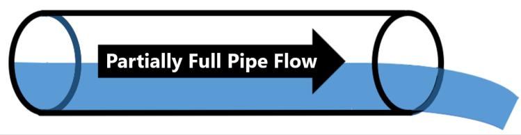
Flow measurement accuracy depends upon the characteristics of flow within the pipe. The speed or velocity of water flowing in a pipe is not the same for all water in the pipe. Water flowing next to the pipe wall flows slower because of friction against the pipe wall, while flow in the center of a pipe flows faster (Figure 1) When water goes through or past a fitting (elbow, tee, reduction, expansion, valve) or through a pump, the flow velocity becomes distorted and no longer follows the pattern shown in Figure 1. This can be a problem for flow measurement accuracy. Many flow meter technologies rely on the type of velocity pattern shown in Figure 1. This type of pattern only develops in pipes that are flowing completely full. Partially full flow can occur when a pipe has an open discharge or when air is trapped in a pipeline (Figure 2 and Figure 3). When a pipe is partially full, the velocity pattern is very different from full pipe flow and the flow area (cross-section) differs also. Many flow meters also rely upon the flow area for flow estimation.


3 of 14
Figure 1. Drawing of Flow Velocity (Speed) in a Full-Flowing Pipe
Figure 2. Drawing of a Pipe With an Open Discharge Flowing Partially Full
Figure 3. Drawing of Partially Full Pipe Flow Caused by an Entrapped Air Pocket
Ensuring Proper Flow Conditions
Proper Velocity Distribution
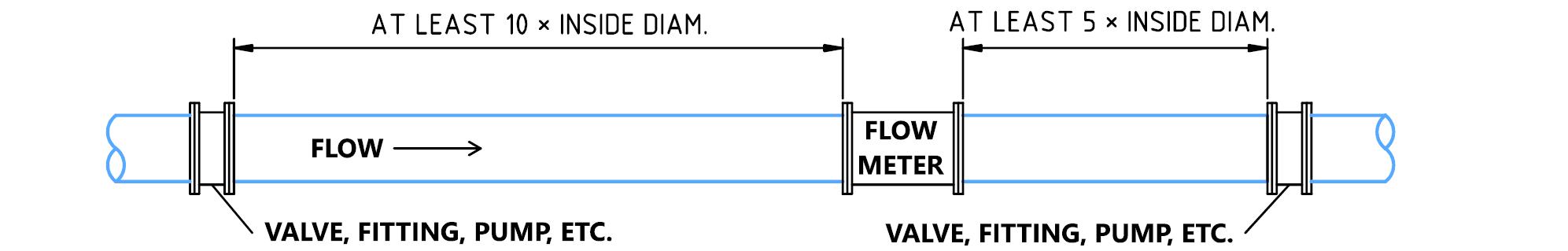
Proper installation and management of a flow meter include taking measures to ensure proper flow conditions. The installation should include a sufficiently long section of straight, full-flowing pipe without fittings so that the desired velocity distribution can develop in the pipe. Generally, this requires that the pipe be straight and free of fittings or valves for at least ten times the inside diameter of the pipe upstream of the flow measurement device and at least five diameters downstream of the device (Figure 4). This can be called the “10-5 Rule.” For example, a flow meter is installed in a 10-inch, Class 100, IPS, PVC pipeline. This type of pipe has an inside diameter of about 10.2 inches. So, the flow meter would need at least 10 × 10.2 inches = 102 inches of straight pipe upstream of the meter and at least 5 × 10.2 inches = 51 inches downstream of the meter. So, this installation would require 102 inches + 51 inches = 153 inches or 12 feet 9 inches of straight pipe (not including the meter length itself).
Exceptions to the 10-5 Rule
The 10-5 Rule is not absolute. Follow manufacturer guidelines regarding installation if they require longer lengths of pipe. However, great care should be taken when following guidelines that suggest smaller distances than the 10-5 Rule unless a qualified, independent, testing laboratory generated the information. That said, some situations and some flow meter technologies may provide accurate measurements with smaller lengths of straight pipe. For example, many flow meters and metering configurations have been tested by the Utah Water Research Laboratory (UWRL) at Utah State University, a world-class water laboratory (https://uwrl.usu.edu/).
The Idaho Department of Water Resources requires flow meters qualifying under their jurisdiction be tested at the UWRL. They have published a list of flow meter models that meet their requirements, available at https://extension.usu.edu/irrigation/measurement and https://idwr.idaho.gov/wpcontent/uploads/sites/2/water-measurement/Approved-flow-meter-list-v3.8_4_4_2022.pdf. Under their requirements, electromagnetic meters (magmeters) and spool-type ultrasonic meters may have as little as three times the pipe inside diameter of straight pipe upstream and at least two times the inside diameter of straight pipe downstream of the meter. Other meter types do not meet this recommendation. Note that at this fact sheet’s publication, the State of Utah did not have specific guidelines for agricultural irrigation flow measurement. As such, it is recommended to use those from Idaho.
Researchers in Nebraska found that some spool-type magmeters could function with as little as two pipe inside diameters of straight pipe upstream and one inside diameter of straight pipe downstream (Eisenhauer et al., 2021). However, this would apply only to the model of meter that they tested. Conversely, Taghvaeian (2017) lists examples where much more length is needed than the 10-5 Rule for ultrasonic flow meters
4
14
of
Figure 4. Recommended Minimum Straight Pipe Requirements for a Pipe Flow Meter (the 10-5 Rule)
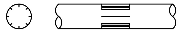
Sometimes, straightening vanes may be placed in a pipe to reduce the necessary straight pipe length (Figure 5). This application may be necessary, for example, with a propeller meter (Eisenhauer et al., 2021).
Full Pipe Flow
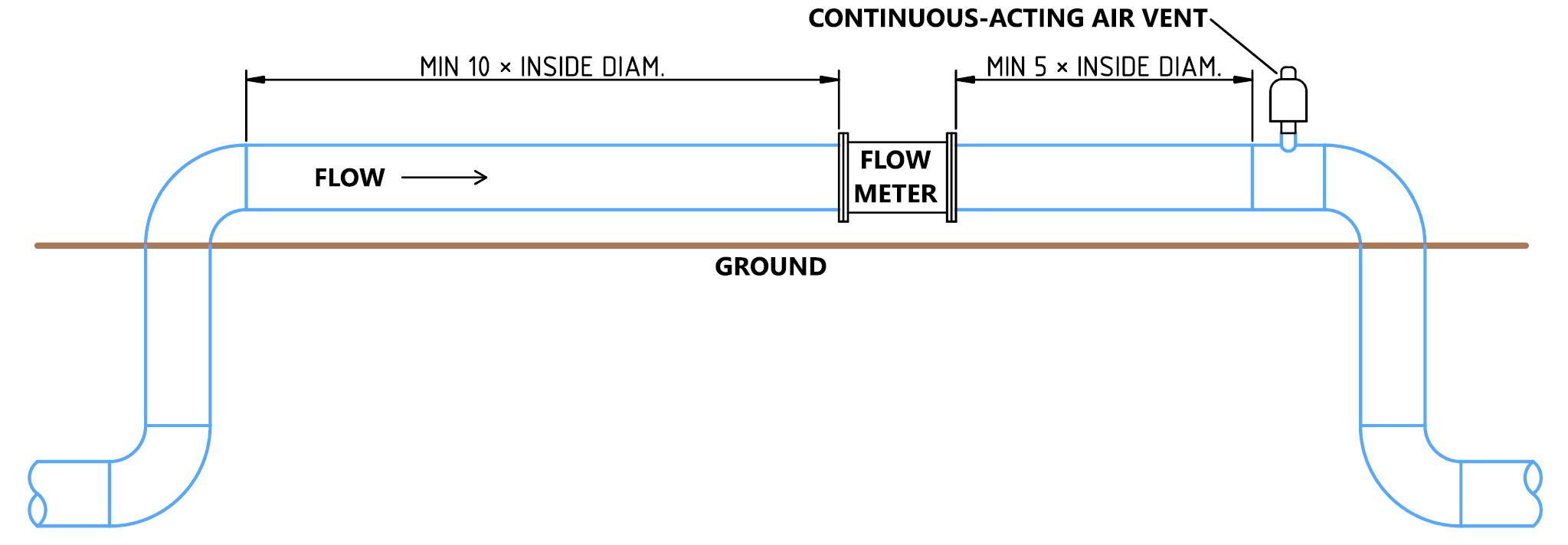
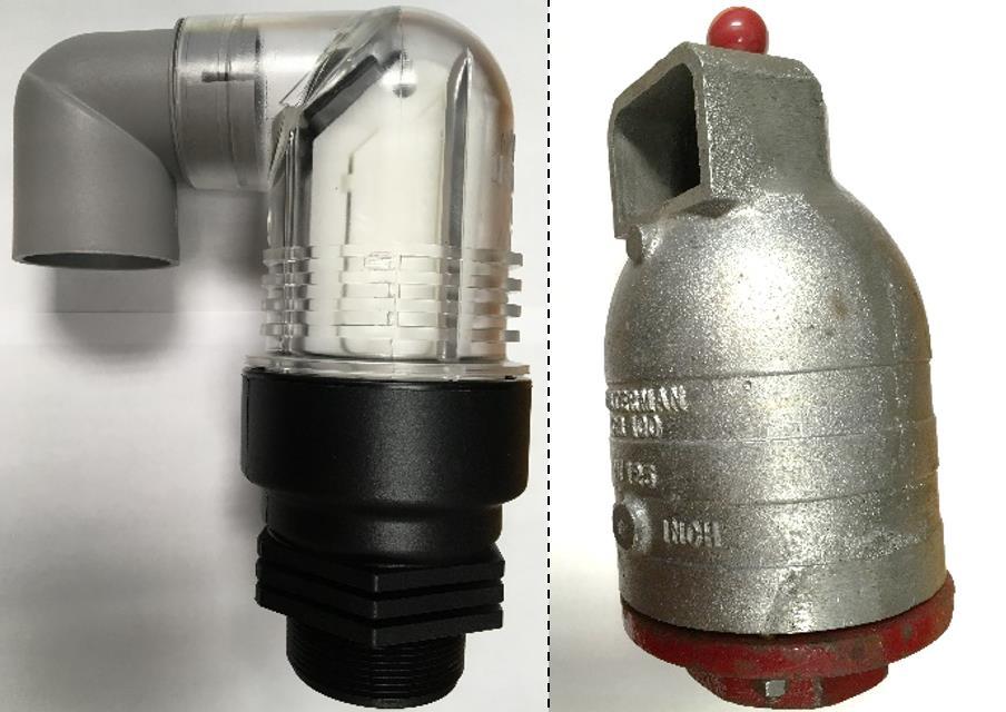
Full pipe flow is not guaranteed even in sprinkler and drip irrigation systems. A flow meter may be positioned in a segment of pipe that could collect air, for example, a segment of aboveground pipe that feeds a buried pipe (Figure 6) Whenever a flow meter is installed in a section of pipe that is higher than the surrounding pipe, a continuous-acting air vent should be installed in the pipe segment to bleed off any entrapped air (Figure 7) An air vent/vacuum release valve that is not continuously acting will not bleed off entrapped air during operation.
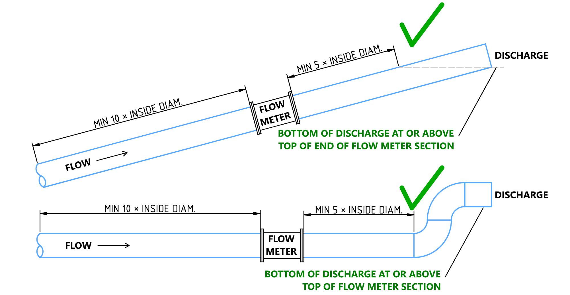
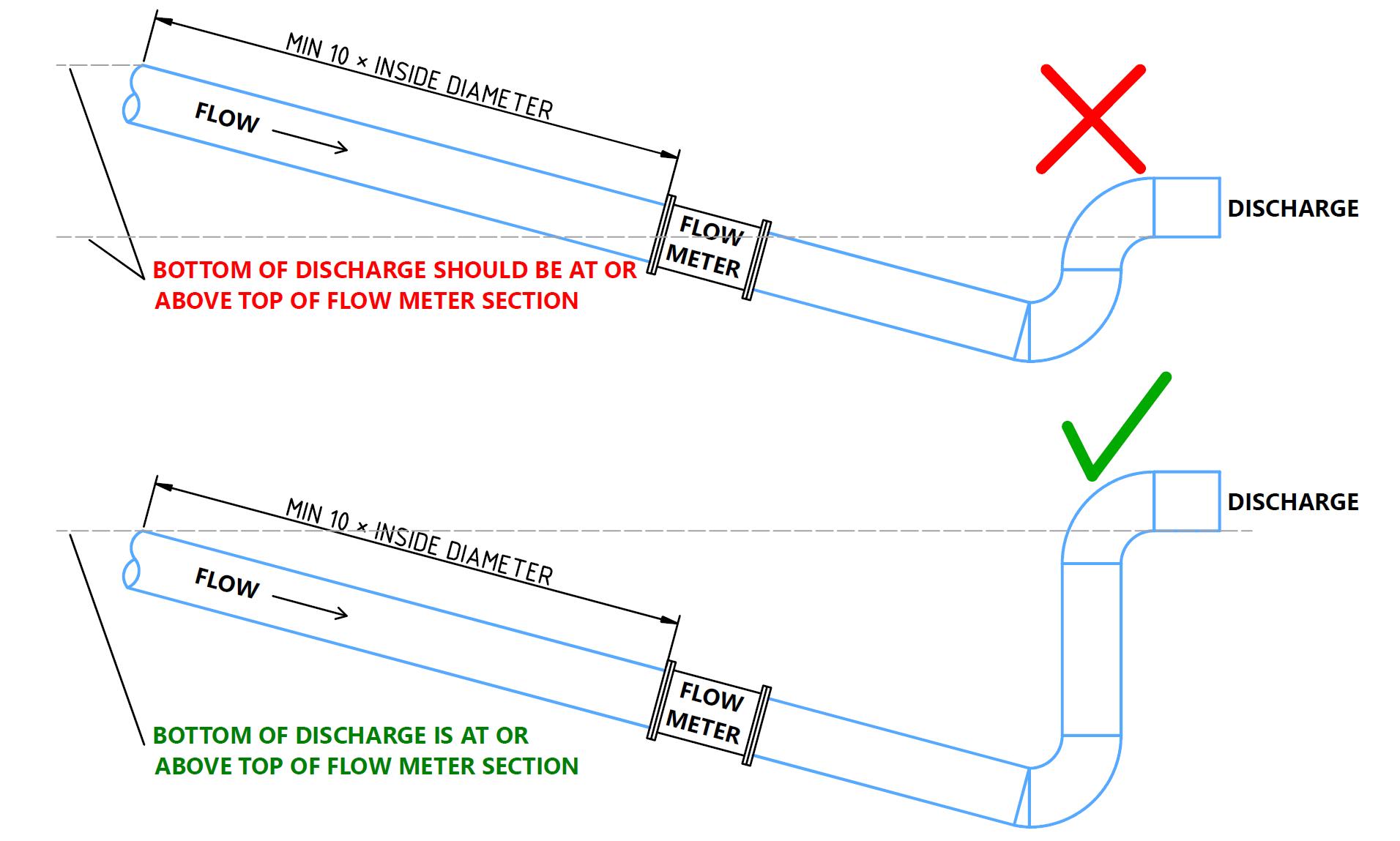
For open discharge systems, like those used to supply a head ditch for surface irrigation, there is often a risk of the pipe flowing partially full. In these cases, a small rise can be added using elbows or pipe miters to ensure the pipe flows fully through the flow meter (Figure 8; Eisenhauer et al., 2021). Other situations may exist or can be designed to ensure full flow through the flow meter (Figure 9). The principle is that the pipe should flow full for the required distances upstream and downstream of the meter (Figure 10).
Finally, many flow meters can be mounted in vertical pipe sections. However, the same required straight pipe distances apply. Manufacturers typically recommend that water flows upward through the pipe section and flow meter (for example, McCrometer, Inc., 2021).
5 of 14
Figure 5. Depiction of Straightening Vanes in a Pipe: Cross-Section View (left) and Side Cutaway (right)
Figure 6. A Flow Metering Situation That May Require a Continuous-Acting Air Vent

6 of 14
Figure 7. Examples of Continuous-Acting Air Vents (left) ACV200 Air Control Valve from Nelson Irrigation Corporation, Walla Walla, WA; (right) CR100 Continuous-Acting Air Vent and Vacuum Relief Valve From Waterman Valve, LLC, Exeter, CA
Figure 8. Pipe at Risk of Flowing Partially Full (top) and Pipe With a Rise After the Flow Meter (bottom)
7 of 14
Figure 9. Pipes Not at Risk of Flowing Partially Full
Figure 10. A Pipe at Risk of Flowing Partially Full Upstream of the Flow Meter (top) and Problem Remedied (bottom)
Flow Meter Types
There are several types of flow meters common in agricultural applications. Flow meters can be categorized by measuring, mounting, and readout methods
Flow Meter Measurement Types
There are several flow measurement types commonly used to measure water flow in pipelines. Only some of these are common in agricultural irrigation (Table 2) Example photos of some of these technologies are provided in Figure 11
8 of 14
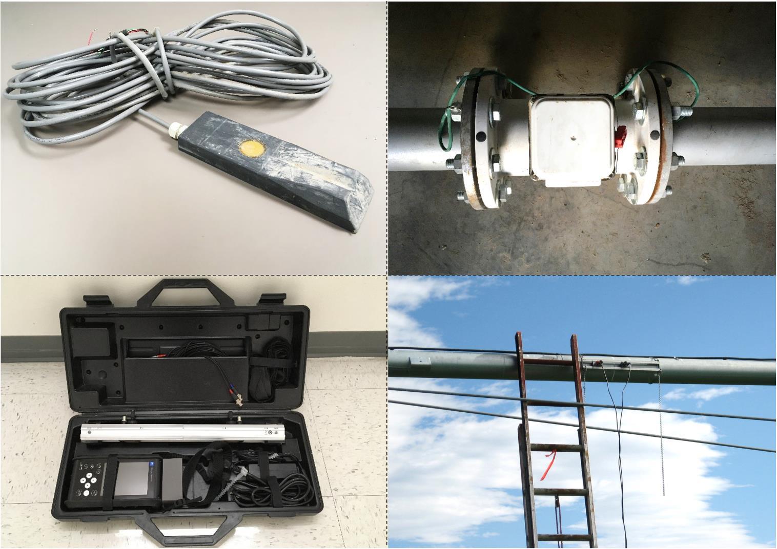
Figure 11. Pipe Flow Meters
(top left) Doppler Meter for Pipe-Bottom Installation (Can Measure Partially Full Flow); (top right) Spool-Type Magmeter; (bottom left) Transit Time Flow Meter in Carrying Case; (bottom right) Transit Time Flow Meter Installed on a Center Pivot Lateral
Table 2. Comparing Flow Meter Measurement Types
Mechanical meters
Propeller/ Turbine meter
Paddle wheel
A propeller or turbine is placed in the pipe (typically centered and pointed upstream). Velocity is based on the rotational speed of the propeller.
A small paddle wheel is placed inside the pipe (typically centered horizontally). Velocity is based on the rotational speed of the paddle wheel.
Electronic meters
Electromagnetic (magmeter)
Generates a magnetic field and measures flow based on distortion of the field. These meters require proper grounding.
Transit time meter
Measures the time an ultrasonic wave takes to travel from a transducer through a pipe to a second receiving transducer. The travel time is related to flow velocity.
Doppler meter1 Sends sound waves into the water and measures the speed of the waves reflected off particles in the flow. Velocity is based on the speed of the reflected waves.
Pressure reduction
Venturi A tapered pipe constriction causes a pressure difference in the pipe. The flow velocity is based on the physics of water flow.
Orifice plate
A flat plate with a hole in it is placed in the pipe. The flow velocity is based on the pressure difference between the two sides of the plate and the physics of water flow.
1See Masasi et al., 2017
Yes Among the least expensive options. Installation can be easier than other methods.
Yes
Yes One of the more accurate methods. No moving parts. Based on flow rate, not velocity. May require less straight pipe than other methods.
Sometimes Some can be installed on the outside of a pipe, not requiring additional fittings. No moving parts.
Sometimes
Strongly affected by the flow velocity distribution. Prone to mechanical wear, which causes inaccurate readings. The meter can collect debris.
More costly than some other options. The installation often requires more effort than other technologies.
More costly than some options. The meter must be protected from the elements. Not best for corroded pipes.
Rarely Can be quite accurate. No moving parts. Relies on accurate pressure measurements.
Rarely
9 of 14
Meter types Function Used in irrigation? Some pros Some cons
Flow Meter Mounting Types
There are several common methods for mounting pipeline flow meters (Table 3). Some measurement technologies may be available in multiple mounting configurations. Example drawings of some of these mounting methods are provided in Figure 12
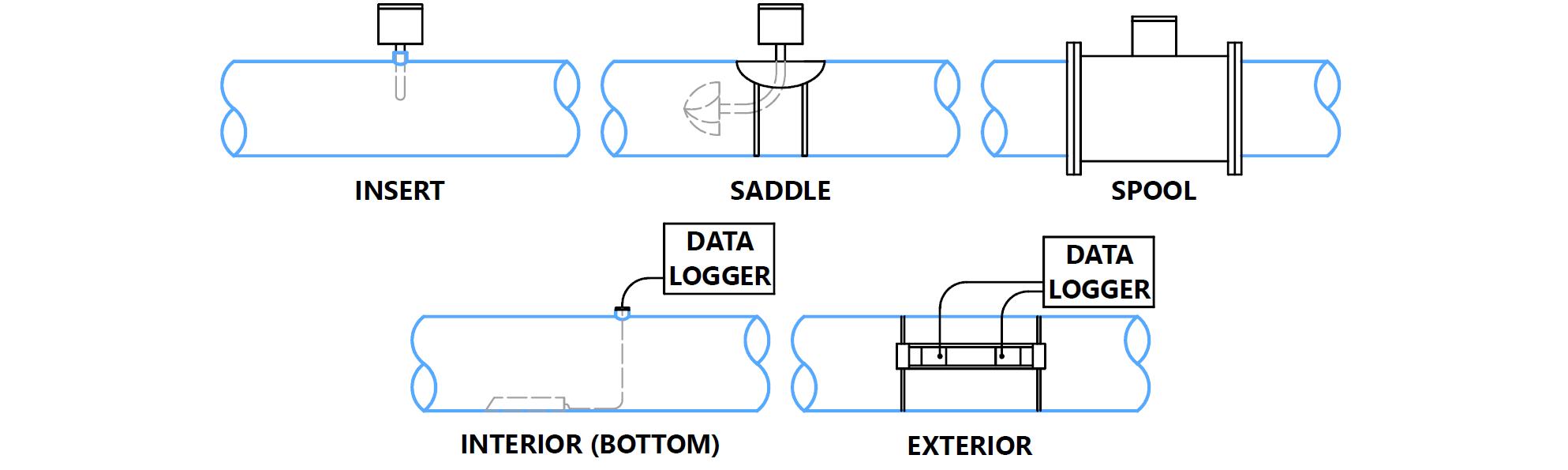
Mounting types
Insertion The meter is typically cylindrical and of relatively small diameter (< 2") The meter is inserted through a threaded outlet (tee or half coupler) in the pipe.
Saddle A hole is cut in the top of the pipe to accommodate the flow meter. The flow meter is attached to a saddle, much like a repair saddle, to cover the hole.
Spool/ Fitting
The meter is a cylindrical fitting, typically flanged, that must be mounted in the pipe and through which water flows.
Paddle wheel magmeter propeller/ Turbine
Propeller/ Turbine magmeter
Among the least expensive options. Installation is often relatively simple
Among the least expensive options. Installation is often relatively simple.
Strongly affected by the flow velocity distribution. The meter can collect debris.
Strongly affected by the flow velocity distribution. The meter can collect debris.
Interior wall mount
The meter is mounted to the inside (often bottom) of the pipe and the sensor cable must be routed out through a fitting or the pipe discharge.
Exterior Transducers are mounted on the exterior of the pipe.
Magmeter propeller/ Turbine venturi orifice
Can be a more accurate option, depending on the meter technology.
Doppler Among the least expensive options. Installation is often relatively easy.
Transit time doppler
The least expensive of mounting methods.
Can cost more than some options. Installation is often more involved.
The sensor can collect sediment.
The mounting location must be protected from the elements.
10 of 14
Table 3. Comparing Flow Meter Mounting Types
of meters Some pros Some cons
Description Types
Figure 12. Three Types of Pipeline Flow Meter Mounting Methods, With Dashed Lines Representing Items Inside the Pipe
Flow Meter Recording Types
The output of flow meter readings can differ among flow meters, with multiple options available for many meters. For example, a meter may only have a manually readable dial, or it may have datalogging capacity and remote access using a cellular connection (Table 4).
Recording types
Needle/ Totalizer
An indicator with a needle (like a speedometer) and a rotating totalizer (like an odometer). Measurements are recorded manually.
Propeller/ Turbine
Among the least expensive options.
Often, there is no data logging or remote access.
Electronic display/ Totalizer
Like a needle/totalizer but a digital display is used. Measurements are recorded manually.
4-20 mA An electrical current output is generated ranging from 4 to 20 mA.
Propeller/ Turbine paddle wheel magmeter
The totalizer is more accurate than the needle or instantaneous value.
0-5 V An electrical voltage output is generated ranging from 0 to 5 V.
All Pulse output An electrical output is generated with pulses which can be DC (on/off) or AC.
Digital output A digital signal is output by the meter. Common standards include SDI-12, RS-232, and MODBUS.
Built-in datalogging
The meter is equipped with a built-in datalogger.
Flow Meter Accuracy
Many
All Can be added to many meters to adapt to external dataloggers. These are common outputs readable by many types of dataloggers.
Many Can be read by many types of dataloggers.
Transit time/ Doppler/ Some others
No external logger is needed.
The signal generator may be an added expense to a meter. It does not include a display or datalogging on its own. Thus, it requires an additional datalogger and telemetry (for remote access).
Digital output may be more expensive than other electrical signal options (above).
Less common. Data typically needs to be downloaded with a computer. Remote access may not be an option.
The accuracy of flow measurements depends upon the meter technology, manufacturer, installation, maintenance, and other factors (Table 5). It is important to consider the accuracy of a meter before purchase. Select meters with no greater than ±2% flow error in the range of expected flow rates. Sensor accuracies will often be described as a percentage plus or minus the measured flow rate. Some accuracies are described in terms of a percentage of velocity measurement and a separate percentage of flow depth measurement (for
11 of 14
Table 4. Comparing Flow Meter Data Output Types
of meters Some pros Some cons Notes
Description Types
example, doppler meters used for partially full flow measurement). A rough approximation is to combine those accuracies as follows:
��������������������������%= 100 (1
Example
��������������������������������% 100 )×(1 ��������ℎ����������������% 100 )×100
A flow meter has a depth accuracy of ±2% and a velocity accuracy of ±5%. Compute the total accuracy. The answer is: total accuracy = 100 – (1% – 2% ÷ 100) × (1% – 5% ÷ 100) × 100 = 100 - (1 – 0.02) × (1 –0.05) × 100 = 100 – 0.98 × 0.95 × 100 = 100 – 0.931 × 100 = 100 – 93.1 = 6.9%. The total accuracy of the meter is ±6.9% of the reading. So, if the meter measured a flow of 100 gpm, the accuracy would be ±0.069 × 100 gpm = ±6.9 gpm. The actual flow could be anywhere from 93.1 gpm to 106.9 gpm.
Some accuracies are presented as a percentage of the full range, meaning the full sensor range. If the sensor range is 10 gpm to 1,000 gpm and the accuracy is ±1% of the full range, then the accuracy is (1,000 gpm – 10 gpm) × 1% ÷ 100 = 9.9 gpm. This accuracy is approximately ±1% at 1,000 gpm but nearly ±100% at 10 gpm. Some accuracies are also provided in absolute terms, like ±1 gpm or a combination of the above-stated methods.
It is important to understand that the accuracy of many types of sensors can drift, or decrease, over time. This is true for many types of flow meters. For example, Masasi and others (2017) found sensor drift in some types of ultrasonic sensors. Sensors that have moving parts are subject to bearing wear and subsequent calibration drift. Follow manufacturer recommendations for maintenance and recalibration.
1As reported by the manufacturers. Accuracies may differ from the manufacturer’s statements (see Masasi et al., 2017). Accuracies should be obtained from a qualified, third-party testing facility. Sensors may also be subject to calibration drift. Manufacturers/sources included: aBadger Meter, FloCat, Instrumart; bGeorge Fischer Signet, Instrumart, Seametrics, McCrometer; cGeorge Fischer Signet, Instrumart; dDirect Pivot Parts, Geyser, Insrumart, McCrometer; eBadger Meter, Fuji Electric, Instrumart, Panametrics; fIn-Situ, Measuring and Control Equipment, Sontek; gIn-Situ, Measuring and Control Equipment. Information was retrieved November 2022.
2Depends on the flow rate and manufacturer.
3Masasi and others (2017) found the range to be much larger and to be biased low.
4Based on costs from online sources and quotes. Costs do not include installation, including pipe cutting, welding, flanges, half couplings, or other materials. Costs typically include signal output (for example, 4-20 mA), and many include totalizer displays. Only ultrasonic and area-velocity meter costs include data datalogging capability. The cost for a datalogger and telemetry can vary depending on the manufacturer and customization. For example, a datalogger
12 of 14
Flowmeter type Mount type Claimed accuracy1 Potential 2022 cost4 Magmeter Spool ±0.2%–0.75%a $380–$450 per diameter incha Magmeter Insertion ±0.5%–10%2,b $1,500–$2,500a Paddle wheel Insertion ±3%–10%c ~$1000a Propeller/Turbine Saddle ±2%d $1,000 + $80 per diameter inchb,c Propeller/Turbine Weld-on saddle ±2%d $180 per diameter inch, more for < 8 inchesb Propeller/Turbine Spool ±2%d $370 per diameter inchb Ultrasonic Exterior ±1%–1.5%3,e $7,100–$11,000a Ultrasonic Insertion ±1%g ~$7,200d Ultrasonic Interior wall ±1%–2%f $8,200–$11,400d,e
Table 5. Comparison of Potential Flow Meter Accuracy and Equipment Cost
may be less than $300 but may be $1,350 or more if telemetry is added. Telemetry service and data hosting services are often an additional annual cost. Sources include: aInstrumart; bDirect Pivot Parts; cMcCrometer, dIn-Situ; eSonTek. Costs are from November 2022.
Flow Meter Cost
The cost of flow meters depends upon the technology, mounting type, data collection system, manufacturer, installation, longevity, and maintenance. Maintenance and longevity information is difficult to obtain, but many equipment dealers can provide general information on these subjects. Table 5 contains a range of installation costs for different flow meter technologies
Summary
When considering a pipeline flow meter, it is important to consider the meter technology and ensure proper flow conditions. When no other information is available, apply the 10-5 Rule The meter’s accuracy should be no greater than ±2% of the flow as tested by a reputable third party. It is important to consider sensor accuracy drift and maintain the meter to minimize drift. Consult equipment dealers regarding the expected longevity of the flow meter under consideration. The cost of flow measurement includes not only the meter itself but also the cost of installation, maintenance, signal output, datalogging, remote access telemetry, and data hosting services. Considered both accuracy and cost when selecting a flow meter because the value of the right to use water in crop production is so great.
References
Eisenhauer, D. E., Martin, D.L., Heeren, D. M. & Hoffman, G. J. (2021). Irrigation systems management. American Society of Agricultural and Biological Engineers. https://asabe.org/ism
Masasi, B., Frazier, R. S., & Taghvaeian, S. (2017). Review and operational guidelines for portable ultrasonic flowmeters [Fact sheet BAE-1535]. Oklahoma State University
Extension https://extension.okstate.edu/fact-sheets/review-and-operational-guidelines-for-portableultrasonic-flowmeters.html
McCrometer, Inc. (2021). Ultra mag electromagnetic flow meter: Installation, operation and maintenance manual [30119-03 Rev. 6.6] https://www.mccrometer.com/ultra-mag/productdownloads?id=52003823655
Taghvaeian, S. (2017) Irrigation water flow measurement [Fact sheet BAE-1502]. Oklahoma State University Extension https://extension.okstate.edu/fact-sheets/irrigation-water-flow-measurement.html
Disclaimers
All figures and photos are by Burdette Barker and require attribution.
In its programs and activities, including in admissions and employment, Utah State University does not discriminate or tolerate discrimination, including harassment, based on race, color, religion, sex, national origin, age, genetic information, sexual orientation, gender identity or expression, disability, status as a protected veteran, or any other status protected by University policy, Title IX, or any other federal, state, or local law. Utah State University is an equal opportunity employer and does not discriminate or tolerate discrimination including harassment in employment including in hiring, promotion, transfer, or termination based on race, color, religion, sex, national origin, age, genetic information, sexual orientation, gender identity or expression, disability, status as a protected veteran, or any other status protected by University policy or any other federal, state, or local law. Utah State University does not discriminate in its housing offerings and will treat all persons fairly and equally without regard to race, color, religion, sex, familial status, disability, national origin, source of income, sexual orientation, or gender identity. Additionally, the University endeavors to provide reasonable accommodations when necessary and to ensure equal access to qualified persons with disabilities. The following individuals have been designated to
13 of 14
handle inquiries regarding the application of Title IX and its implementing regulations and/or USU’s non-discrimination policies: Executive Director of the Office of Equity, Matt Pinner, JD, matthew.pinner@usu.edu, Title IX Coordinator, Hilary Renshaw, hilary.renshaw@usu.edu, Old Main Rm. 161, 435-7971266. For further information regarding non-discrimination, please visit equity.usu.edu, or contact: U.S. Department of Education, Office of Assistant Secretary for Civil Rights, 800-421-3481, ocr@ed.gov or U.S. Department of Education, Denver Regional Office, 303-844-5695 ocr.denver@ed.gov. Issued in furtherance of Cooperative Extension work, acts of May 8 and June 30, 1914, in cooperation with the U.S. Department of Agriculture, Kenneth L. White, Vice President for Extension and Agriculture, Utah State University.
April 2023
Utah State University Extension
Peer-Reviewed Fact Sheet
14 of 14
