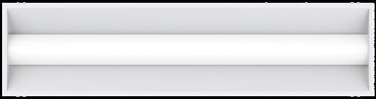
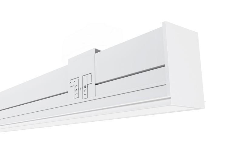
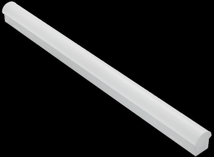
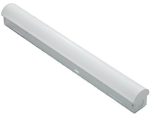
Carisma Pendant is part of a family of architectural linear luminaires that offer excellent performance, quality, visuals and value. A sleek edge-to-edge lens design results in an elegant aesthetic with clean lines. Carisma’s patent pending design includes an integrated optical system that minimizes optical losses, allowing for industry-leading efficacy that meets the stringent requirements for DLC Listing (DLC Listing pending). A tailored end cap design and Amerlux’s trusted catch-and-latch mechanism prevents all light leakage.
The Carisma Pendant offers luminaires with 2” and 3" wide apertures, delivering seamless lighting as discrete individual fixtures, continuous rows or patterns. Carisma can be specified to the nearest 1/8” and is available in pendant, surface, wall and recessed mounting options, providing designers with the versatility to light up a space with their Carisma.
Product Overview
Type: Direct distribution with pendant, surface or wall mounting
Wattage: 5W/ft, 10W/ft (or specify wattage between 3W/ft and 10W/ft)
Color Temp: 2700K*, 3000K, 3500K, 4000K (* 90+ CRI only)
CRI: 80+ or 90+
Dimming (wired): 0-10V, 1% dimming (standard) Lutron LDE1 Hi-lume® 1% Soft-On/Fade-to-Black DALI dimming, 1% dim
EMC-PF2 - emergency circuit requires power feed located in last fixture section (for other locations consult factory)
PF2 - Extra power feed for additional circuiting
EMB - emergency battery pack (not available for lengths under 4')
Carisma
Carisma 2” Direct
Linear Direct LED
PROJECT:
Specifications
Construction
Extruded aluminum housing and reflector. Die-cast end caps match fixture body finish.
Weight: 2.5 lbs/ft (may vary based on configurations and accessories)
Optical
All lenses are snap-in, extruded acrylic, with a maximum length of 8’. Amerlux's proprietary acrylic lens provide excellent transmission while effectively concealing source image.
PL - Performance Lens provides high efficiency with controlled lens surface brightness.
ASY - Asymmetric throw lens.
LED
Our LED binning is within 3 MacAdam ellipse. Boards are configured for maximum flexibility resulting in even illumination no matter the fixture layout.
LED boards are easily replaced in the field with just a Phillips screw driver.
Color Temperature Options: 2700K*, 3000K, 3500K, 4000K
CRI: 80+, 90+
R9: 16 @ CRI 83; R9: >50 @ CRI 92
Life: 50,000+ hr., > 70% of initial lumens (L70)
* Available in 90+ CRI only
Electrical
Wiring: Individual and "Beginning of Run" (BOR) fixtures are prewired with power cord. All configurations have quick connect power harnesses for row connections.
Standard Wattage: 5W/ft, 10W/ft.
Optional Wattages: 3W/ft, 4W/ft, 6W/ft, 7W/ft, 8W/ft, 9W/ft. (3W & 4W have a minimum length of 3'). For other wattages consult factory. Emergency circuit via remote inverter or auxiliary emergency power supply (by others). This product complies with IEEE C62.41 for surge endurance up to 2.5KV. Amerlux® recommends using additional surge protection with this unit (supplied by others), surge and over voltage damage is not covered under warranty.
EMC-PF - Emergency circuit requires power feed to be located in last fixture section for continuous runs. For other locations consult factory. Not available for individual (IND) configuration.
PF - Extra power feed for additional circuiting. Not available for individual (IND) configuration.
Finish
All painted surfaces are premium powder coated baked on for maximum durability and color stability.
HW - High reflective matte White
BT - Black Texture
ST - Silver Texture For special paint colors supply RAL and/or actual paint chip for factory consultation.
Configurations/Lengths
Straights:
IND - Individual fixtures are made of single standard lengths of 2 ft to 8 ft (in 1' increments). These are stand alone fixtures with matching End Caps, supplied with the mounting hardware. Lengths less than 4' may have restrictions based upon wattage, lengths, drivers or other options.
CON - Continuous runs, > 8' specified to nearest whole foot length in 1' increments. Runs made from standard lengths have End Caps at the beginning and end of run. Runs > 60' may require second power feed. Each housing has factory installed alignment pins. Mating fixtures are easily aligned and joined. Wiring is made fast and positive with molded quick connectors.
CUS - Custom made to measure runs are made to nearest 1/8"of customer supplied field measurements or drawings. Custom lengths use the same hardware for hairline joining.
TYPE:
Patterns:
PXX- Standard Patterns consist of 90º corners with standard lengths (4' to 8' in 1' increments), continuous runs or made to measure lengths. Depending upon complexity of the pattern drawings may be required from the customer. If ordering please give overall lengths.
A'-B'-PLL - L Left - (1) 90º Corner 2 segments. Specify overall segments: A’ & B’
A'-B'-PLR - L Right - (1) 90º Corner 2 segments. Specify overall segments: A’ & B’
A'-B'-C'-PZ - Z shape - (2) 90º Corners joining 3 segments. Specify overall segments: A’, B’, & C’ See page 6 for layouts.
Mounting
The Carisma Direct is intended for pendant, surface or wall mounting.
Pendant Mount-ASWxx - Direct pendant munted in center of ceiling tile or gypsum board ceiling (standard) i.e. ASWxx. Or if canopy is installed on a grid Tee runner add, T i.e. ASWxxT.
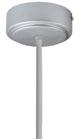
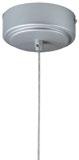
Cable is stranded stainless steel wire. All fittings are protected against rust and corrosion. Canopies are 5" x 1/4" die formed painted steel. Adjustment mechanism allows for infinite height adjustment. Amerlux recommends the required feed and non-feed suspensions based upon length and electrical options. Options include: color of canopy and power cord (black or white), length 4', 10' or 20', and mounting condition, in center of ceiling tile and in gypsum board ceiling (standard) i.e. ASWxx. Or if canopy is installed on a grid Tee runner add, T i.e. ASWxxT
Wall Mount-WM - Direct wall mounted using steel cleat bracket attached to fixture housing and wall bracket with set screws. Two bracket assemblies are used for each length. A third center bracket may be recommended. J-box required at feed locations.
Surface Mount-SM - Direct surface mounted - housing needs to be attached to solid structure above. Mounting holes are pre-drilled at factory. Some fixture disassembly and reassembly required. Mounting hardware by others.
Options
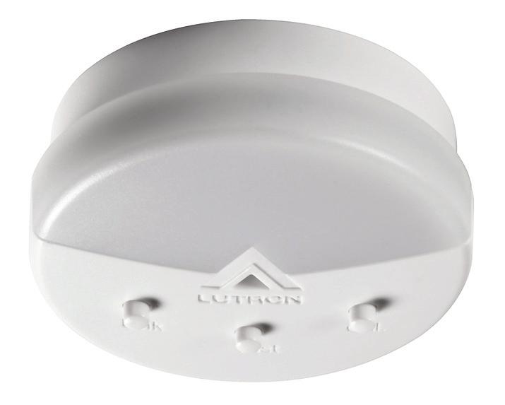
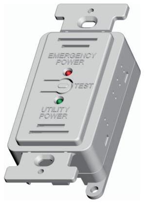
EMB - Emergency battery pack - 10W output power, 90 min of illumination time, up to 1300 lm of initial light output. Illuminated test-switch/charging indicator light is provided. Wattage consumption by EM: 2.5W/ft (4ft fixture), 1.25W/ft (8ft fixture). Request can be made to light up 4ft section on 8ft unit.
Certifications
Approved to UL standards for damp locations as tested by CSA
Intended for indoor use only
DLC Listing pending
Warranty
Amerlux's 5 year limited warranty. Please consult Amerlux website for details.
Carisma 2” Direct
Linear Direct LED
PROJECT: TYPE:
Carisma
Carisma 2” Direct
Linear Direct LED
PROJECT:
TOOLLESS JOINING
Line up the two housings using the alignment brackets. Secure them together by using the Catch & Latch System on the top of the extrusion.
CABLE KIT SUSPENSION OPTIONS:
J-Box secured to structure above by others
Screw
TEE GRID OR SCREW SLOT (ASW10T, ASW20T, ASB10T, ASB20T) FEED
Amerlux® has partnered with control companies to create building environments that are safer and smarter than ever before. At the heart of our partnership is intelligent RF nodes and Smart Sensor, the most advanced digital wireless communication and sensors available today. Integrated into Amerlux products.
Minimum run length is 3' for wireless sensor and RF node.
INDIVIDUAL (MIN 3' LENGTH)
CARISMA 2" PATTERNS:
Standard Patterns
All corners are standard 90°, standard length legs. Use standard lengths: 4' to 8' in 1 foot increments. Continuous runs must be the same length in pairs for closed configuration.
Carisma 2" Lens Mitered Lens
PLL - L Left, (2) straights + (1) 90° corner, leg right
PLR - L Right, (2) straights + (1) 90° corner, leg left
Provide overall lengths: A' & B' Nomenclature: A-B-PLL A-B-PLR
Provide overall lengths: A', B' & C' Nomenclature: A-B-C-PZ
Carisma
Carisma 2” Direct
FIXTURE DATA:
Total
Source:
Source: 192 White LED's
Carisma 2” Direct
Total Watts: 20
Total Lumens: 2693
Source: 192 White LED's
Source 192 White LED's
Carisma 2” Direct
Linear Direct LED
PROJECT: TYPE:
DIMMING COMPATIBILITY:
Amerlux® Carisma fixtures are compatible with all major dimming protocols prevalent in the United States. Please see below for general compatibilities and wiring diagrams. Amerlux recommends testing your unique dimming configuration as the exact full configuration (Dimmer, Fixture Quantity, Voltage, etc) may affect dimming performance.
--- NOTE: INFORMATION BELOW IS FOR WIRED DIMMERS ONLY. FOR WIRELESS DIMMERS, CONSULT
0-10V - DIMMING (Standard)
Integrates into a variety of building management and daylighting controls
Notes:
• 120VAC or 277VAC*
• Dims down to 1% light output
• Requires interface to turn off power to driver
• Consult Dimming manufacturer for installation instructions - DO NOT SHARE NEUTRALS!
Compatible Dimmers†:
Wall Box
Lutron: Wattstopper: Leviton:
Diva - DVSTV ADF-120277 Renoir II
Maestro - MS-Z101
Nova-T - NTSTV-DV
Center System
Lutron Grafixk Eye with GRX-TV1 Interface
LUTRON LDE1 DIMMING
Integrates into Lutron EcoSystem building management
Notes:
• 120VAC or 277VAC*
• Dims down to 1% Soft-On/Fade-to-Black
• EcoSystem Control
• Consult Dimming manufacturer for installation instructions - DO NOT SHARE NEUTRALS!
Compatible Dimmers†: Lutron ECO System
Pow Pak Dimming Modules
Energi Savr Node
Grafik Eye QS/Homeworks
QS Control Unit
Quantum Hub
Homeworks QS/My Room
Notes:
Central System
Lutron EcoSystem compatible controls
0-10V Wiring Diagram
Lutron LDE1 (HILUME-H-ECO) EcoSystem Digital Control Wiring Diagram
* Driver is 277VAC dimmable with appropriate dimmer (by others). All provided wiring diagrams show 120VAC wiring colors and method.
Please refer to 277VAC dimmer installation instructions for 277VAC wiring diagrams.
† The absence of a dimmer from the lists above does not imply incompatibility. Please consult factory for compatibility inquiries.
Carisma
Carisma 2” Direct
Linear Direct LED
PROJECT: TYPE:
DIMMING COMPATIBILITY:
Amerlux® Carisma fixtures are compatible with all major dimming protocols prevalent in the United States. Please see below for general compatibilities and wiring diagrams. Amerlux recommends testing your unique dimming configuration as the exact full configuration (Dimmer, Fixture Quantity, Voltage, etc) may affect dimming performance.
--- NOTE: INFORMATION BELOW IS FOR WIRED DIMMERS ONLY. FOR WIRELESS DIMMERS, CONSULT FACTORY ---
DALI - DALI DIMMING 120V-277V
Digital control protocol allows individual fixture control
Notes:
• 120VAC - 277VAC*
• Dims down to 1% light output in most cases
Compatible Dimmers†:
Leviton CD250 Controller
Center System
Dynalite Fifth Light DALI Wiring Diagram
EMERGENCY FIXTURE WITH BUILT-IN BATTERY PACK (EMB) WIRING:
Note: EMB not available on lengths under 4'.
EMERGENCY DRIVER
Notes:
* Driver is 277VAC dimmable with appropriate dimmer (by others). All provided wiring diagrams show 120VAC wiring colors and method. Please refer to 277VAC dimmer installation instructions for 277VAC wiring diagrams.
† The absence of a dimmer from the lists above does not imply incompatibility. Please consult factory for compatibility inquiries.
Carisma
NIO-4PSTLNDC
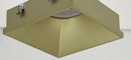
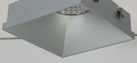
4" Iolite PLUS Square Trimless Reflector
Source: 20W to 28W LED Up to 2850lm
PRODUCT DESCRIPTION
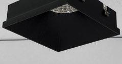
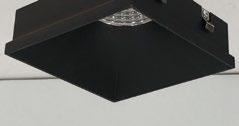
4" PLUS Trimless Iolite reflectors have no exposed trim flange and do not extend beyond the ceiling plane. Iolite PLUS Trimless requires a PLUS Trimless Mud Ring and PLUS New Construction housing. Deep regressed cone reflectors optimize visual cut-off.
FEATURES
Trimless knife edge appearance
Delivering up to 2850 lumens
2 700K, 3000K, 3500K, 4000K, 5000K @ 90+ CRI
· F lood optic, narrow flood and spot optics (included)
5 -Year limited warranty
SPECIFICATION
Construction: Trims are constructed of heat dissipating, die-cast aluminum. Cold forged aluminum LED heat sink is threaded to fit the reflector and transfer heat.
Mounting: Luminaire includes stainless steel friction clips to mount securely to trimless mud ring. Mud ring is required per trimless downlight.
OPTICS
Each luminaire includes field changeable TIR optics (40° spot, 71° flood and 51° narrow flood - preinstalled).
ELECTRICAL
Delivered Lumens / Wattage Up to 2100lm / 20WUp to 2500lm / 24WUp to 2850lm / 28W
Color Temperature 2700K, 3000K, 3500K, 4000K, 5000K
Color Rendering Index 90+ CRI
Compatible Housing
NHIOICD-4PS15
NHIOICDCP-4PS15
NHIOICD-4PS20
NHIOICDCP-4PS20
Lifetime 50,000 hours @ L70
NHIOICD-4PS25
NHIOICDCP-4PS25
Accessories: Luminaires will accommodate (1) translucent deco collar or opaque snoot, no accessory holder is required, see page 2. Mud ring is required (NIO-TLMR-4PS) per trimless downlight.
LABELS AND LISTINGS
· c ULus Listed for Damp Locations
E NERGY STAR certified
5 -Year Limited Warranty
R oHS Compliant
C ertified to the high efficacy requirements of California Title 24 JA8-2022
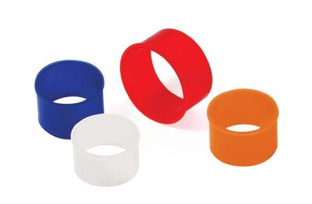
Iolite accessories can be added at any point in the design process. Accessories easily install between LED module and die-cast trim. Luminaire will accommodate (1) hex louver and (1) collar accessory, no accessory holder required.
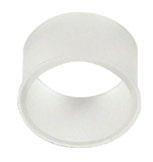
Translucent Decorative Collar
NIO-AS14(color) 5/8" length
NIO-AS19(color) 3/4" length
NIO-AS26(color) 1" length
Color: AM (amber), BLU (blue), FR (frosted), R (red)
Translucent collars color the aperture with the specified color while producing white general light. Collars are available in different lengths. Use to add interest, create a theme, match a theme or define a space.
TRIMLESS
Opaque Collar Snoot
NIO-AS14(color) 5/8" length
NIO-AS19(color) 3/4" length
NIO-AS26(color) 1" length
Color: MPW (matte powder white), WH (white)
Opaque snoot greatly reduces aperture brightness while preserving light output.
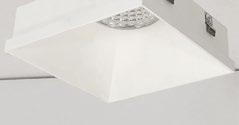
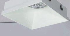
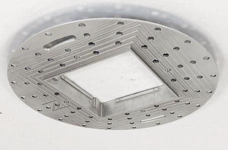
4" Iolite PLUS trimless downlights have no exposed flange and the result is a minimalist knife edge appearance. A trimless mud ring is installed after the drywall and a professional drywall finisher floats the ceiling to blend in the mud ring.
Iolite PLUS Trimless Mud Ring
NIO-TLMR-4PS Square Mud Ring
Mounts trimless downlight with no exposed flange and no extension beyond ceiling plane. Die-cast aluminum mud ring attaches to drywall. Only for use with NHIOICD-4PS new construction housings and NIO-4PSTL trimless.
Dimensions: 7-7/8" diameter 3/5" thick
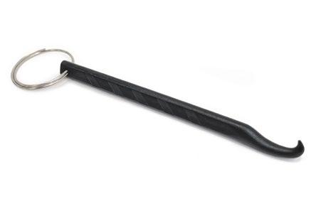
Mud Ring
Removal Tool
6505 Gayhart Street, Commerce, CA 90040 TEL 323.767.2600 | www.noralighting.com e-mail: nora@noralighting.com
Removal Tool
NIO-TLTOOL
Assist removing trimless reflector from finished ceiling after installation. For maintenance on trimless downlight. One is included with each luminaire.
PHOTOMETRICS
4" Iolite PLUS Square Trimless Downlight 1500 lumens
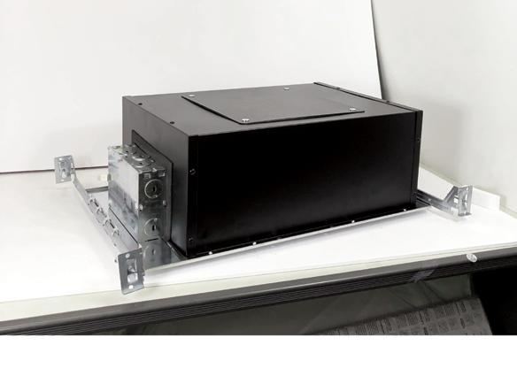
4" Iolite PLUS IC Air-Tight High Lumen New Construction Housing for Square PLUS Trimless Only
Source: 20W to 28W LED 1500lm to 2500lm
PRODUCT DESCRIPTION
New construction housing for use with Square PLUS trimless only. Rated for insulated ceilings and can be in direct contact with insulation. Air-tight construction provides energy savings by reducing the flow of air through the ceiling. Patented design allows for easy, tool-less removal of the driver.
SPECIFICATION
Housing: 0.040 " Aluminum housing can be installed in ceilings up to 1/2" thick.
Patented Driver Assembly: Allows driver to slide out of housing without tools from the room side. Housing includes a removable top cover for driver maintenance above the ceiling.
Air Flow Restriction: Meets requirments of Air-Tight (AT) <2CFM (cubic feet per minute) in accordance with ASTM283 Air-Tight requirements.
Clearance: “IC” Insulated ceiling housings are direct contact rated. Not to be used in direct contact with spray foam insulation.
Bar Hangers: Two 13- 3/4" to 24- 1/2 " adjustable bar hangers with captive nails are included on housing. Bar hanger brackets are parallel to junction box, but can be repositioned 90° perpendicular to junction box if desired. “L”-shaped bar hanger foot to align to bottom of construction joist. A T-bar notch allows for easy installation in a suspended ceiling.
Junction Box: Pre-wired 25 cubic inch 0.064" thick galvanized steel, with seven 1/2 " knockouts, four Romex® pryouts, and snap on covers. All leads are #18AWG wire, the ground wire is connected to the bottom, and quick connectors are supplied on all leads. Maximum of 8 no. 12 AWG through branch circuit conductors suitable for at least 90°C permitted in junction box. Junction box is accessible from the room side through housing opening.
ELECTRICAL 15LE4 15LUPEQ 20LE425LE4
Input Voltage 120/277V
Compatible Trimless NIO-4PSTLA / NIO-4PSTLNDC
COMPATIBLE TRIMLESS
CATALOG NO. DESCRIPTION
NIO-4PSTLA 4" PLUS Square Trimless Adjustable NIO-4PSTLNDC 4" PLUS Square Trimless Downlight
EMERGENCY
Pre-Wired: Housing can be specified with connections for emergency battery installation. Requires access above ceiling. Must specify battery with remote test switch separately (NEPK- 07LEDUNV ).
Note: Pre-Wired is not compatible with Chicago Plenum housings Integrated: Compact emergency driver is mounted directly to the junction box allowing below ceiling access. Compared to traditional emergency driver that are larger and remote mounted which requires access above ceiling. 90 minute illumination time with 6W output in emergency mode. Battery requires 24 hours to recharge and consumes 3W when charging. Remote test switch and 3' cable included.
LABELS AND LISTINGS
c ULus Listed for Damp Locations
E NERGY STAR certified
5 -Year Limited Warranty
· R oHS compliant
F CC compliant
P atent #D824567S
Meets or exceeds ASTM-283 Air-Tight requirements
4" Iolite PLUS Trimless New Construction Housing - Compatible with NIO-4PS square trimless
= IC Air-Tight / 1500lm / 20W
NHIOICDCP-4PS15 = Chicago Plenum / 1500lm / 20W
NHIOICD-4PS20 = IC Air-Tight / 2000lm / 24W
NHIOICDCP-4PS20 = Chicago Plenum / 2000lm / 24W
NHIOICD-4PS25 = IC Air-Tight / 2500lm / 28W
NHIOICDCP-4PS25 = Chicago Plenum / 2500lm / 28W
LE4 = 120/277V input; Triac / ELV / 0-10V dimming LUPEQ = 120/277V input; Lutron Hi-lume Premier 0.1% EcoSystem with Soft-On, Fade-to-Black (consult factory) /EM2 = Integrated Emergency w/Remote Test Switch /PEM = Pre-Wired for Remote (not compatible with NHIOICDCP)
LE4 = 120/277V input; Triac / ELV / 0-10V dimming /PEM = Pre-Wired for Remote Emergency
/EM2 = Integrated Emergency w/Remote Test Switch
Example: NHIOICD-4PS20LE4 = 4" Iolite PLUS Trimless New Construction Housing, 2000lm / 24W, 120-277V input; Triac / ELV
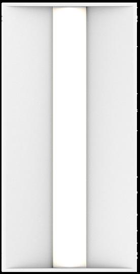
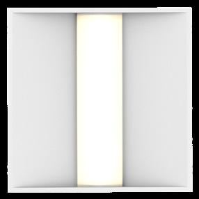
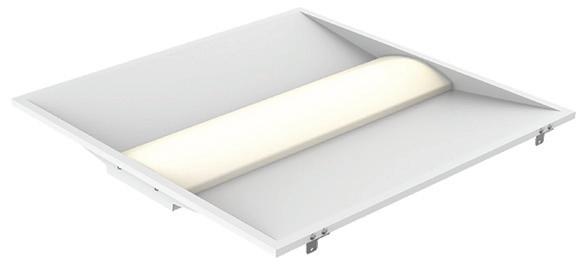
Carisma Recessed is part of a family of architectural linear luminaires that offer excellent performance, quality, visuals and value. A sleek edge-to-edge lens design results in an elegant aesthetic with clean lines. Carisma’s patent pending design includes an integrated optical system that minimizes optical losses, allowing for industry-leading efficacy that meets the stringent requirements for DLC Listing (DLC Listing pending). Wide range of ceiling trim options accommodate most ceiling types.
The Carisma Recessed offers luminaires with 2” and 3” wide apertures, delivering seamless lighting as discrete individual fixtures, continuous rows or patterns. Carisma can be specified to the nearest 1/8” and is available in pendant, surface, wall and recessed mounted options, providing designers with the versatility to light up a space with their Carisma.
Product Overview
Type:
Direct distribution with recessed mounting
Wattage: 5W/ft, 10W/ft (or specify wattage between 3W/ft & 10W/ft)
Color Temp: 2700K*, 3000K, 3500K, 4000K (* 90+ CRI only)
CRI: 80+ or 90+
Dimming (wired): 0-10V, 1% dimming (standard)
Lutron LDE1 Hi-lume® 1% Soft-On/Fade-to-Black
DALI dimming, 1% dim
Dimming (wireless): Enlighted Sensor
Lutron Athena (integral wireless RF node)
Fixture
Runs
Individual Runs: 2' - 8' (specify in 1' increments)
Continuous Runs: >8' (specify to the nearest foot)
Custom: Made to measure lengths available (specify to nearest 1/8" of field dimensions). Requires approval drawings. Added cost & lead time.
Carisma
Carisma 2”
Recessed Linear LED
PROJECT: TYPE:
Ordering Information
Model
CAR2-R-GB - gypsum board trimless mud-in
CAR2-R-FLG - gypsum board exposed flange
CAR2-R-GRID - grid ceiling mount
Optics
PL - performance lens
ASY - asymmetric lens
Wattage (per foot)
Standard:
5 - 5W/ft
10 - 10W/ft
Optional:
3 - 3W/ft (3' minimum length required)
4 - 4W/ft (3' minimum length required)
6 - 6W/ft
7 - 7W/ft
8 - 8W/ft
9 - 9W/ft
Color Temp
80+ CRI: 90+ CRI:
30 - 3000K-80+ 279 - 2700K-90+
35 - 3500K-80+ 309 - 3000K-90+
40 - 4000K-80+ 359 - 3500K-90+
409 - 4000K-90+
Finish
HW - high reflectance matte white
Voltage 120/277
Length x __________________ x __________________ (Length A) (Length B) (Length C)
Length A (used for) Length B (used for) Length C (used for)
- all patterns - all patterns - PU
- IND - PR - 2 lengths - PZ
- CON of 2 - CUS
Configuration
IND1 - individual fixture, 2' to 8' in 1' increments
CON - continuous run > than 8', specify to nearest foot
CUS - custom made to measure lengths (specify to nearest 1/8" of field dimensions)
Standard Patterns (see page 8 for details):
PLL - L left, (2) straights + (1) 90° corner, leg right
PLR - L right, (2) straights + (1) 90° corner, leg left
PU - U shape, (3) straight lengths + (2) 90° corners
EMC-PF2 - emergency circuit requires power feed located in last fixture section (for other locations consult factory)
PF2 - Extra power feed for additional circuiting
EMB - emergency battery pack (not available for lengths under 4')
1 - Lengths less than 4' may have restrictions based upon wattage, lengths, drivers or other options.
2 - Not available with IND (individual) configuration.
Carisma
Carisma 2”
Recessed Linear LED
PROJECT:
Specifications
Construction
Extruded aluminum housing and reflector. Numerous configurations accommodate most architectural ceiling conditions.
Weights: 3 lbs/ft (may vary based on configurations and accessories)
Optical
All lenses are snap-in, extruded acrylic, with a maximum length of 8’. Amerlux's proprietary acrylic lens provides excellent transmission while effectively concealing source image.
PL - Performance Lens provides high efficiency with controlled lens surface brightness.
ASY - Asymmetric throw lens.
LED
Our LED binning is within 3 MacAdam ellipse. Boards are configured for maximum flexibility resulting in even illumination no matter the fixture layout.
LED boards are easily replaced in the field with just a Phillips screw driver.
Color Temperature Options: 2700K*, 3000K, 3500K, 4000K
CRI: 80+, 90+
R9: 16 @ CRI 83; R9: >50 @ CRI 92
Life: 50,000+ hr., > 70% of initial lumens (L70)
* Available in 90+ CRI only
Electrical
Wiring: Supply wires are easily accessible through access plate on top of fixture.
Optional Wattages: 3W/ft, 4W/ft, 6W/ft, 7W/ft, 8W/ft, 9W/ft. (3W & 4W have a minimum length of 3'). For other wattages consult factory. Emergency circuit via remote inverter or auxiliary emergency power supply (by others).
This product complies with IEEE C62.41 for surge endurance up to 2.5KV. Amerlux® recommends using additional surge protection with this unit (supplied by others), surge and over voltage damage is not covered under warranty.
EMC-PF - Emergency circuit requires power feed wire harness to be located in last fixture section for continuous runs. For other locations consult factory. Not available for individual (IND) configuration.
PF - Extra power feed wire harness for additional circuiting. Not available for individual (IND) configuration.
Finish
HW - High reflectance, matte white powder coat paint. Baked on finish for maximum durability and color stability.
Configurations/Lengths
Straights:
IND - Individual fixtures are made of single standard lengths of 2 ft to 8 ft (in 1' increments). These are stand alone fixtures with matching End Caps, supplied with the mounting hardware. Lengths less than 4' may have restrictions based upon wattage, lengths, drivers or other options.
CON - Continuous runs, > 8' specified to nearest whole foot length in 1' increments. Runs made from standard lengths have End Caps at the beginning and end of run. Runs > 60' may require second power feed. Each housing has factory installed alignment pins. Mating fixtures are easily aligned and joined. Wiring is made fast and positive with molded quick connectors.
CUS - Custom made to measure runs are made to nearest 1/8"of customer supplied field measurements or drawings. Custom lengths use the same hardware for hairline joining.
TYPE:
Patterns:
PXX- Standard Patterns consist of 90º corners with standard lengths (4' to 8' in 1' increments), continuous runs or made to measure lengths. Depending upon complexity of the pattern drawings may be required from the customer. If ordering please give overall lengths.
A'-B'-PLL - L Left - (1) 90º Corner 2 segments. Specify overall segments:
A’ & B’
A'-B'-PLR - L Right - (1) 90º Corner 2 segments. Specify overall segments: A’ & B’
CAR2-R-GRID - grid mount in 9/16" & 15/16" Flat Tee, 9/16" Screw Slot or 9/16" Interlude ceilings
Options
EMB - Emergency battery pack - 10W output power, 90 min of illumination time, up to 1300 lm of initial light output. Illuminated test-switch/charging indicator light is provided. Wattage consumption by EM: 2.5W/ft (4ft fixture), 1.25W/ft (8ft fixture). Request can be made to light up 4ft section on 8ft unit.
Certifications
Approved to UL standards for damp locations as tested by CSA
Intended for indoor use only
DLC Listing pending Chicago Plenum (CCEA) optional
Warranty
Amerlux's 5 year limited warranty. Please consult Amerlux website for details.
Carisma 2”
Recessed Linear LED
PROJECT: TYPE:
Method (by others)
Ceiling contractor to spackle, feather and sand at ceiling interface.
Minimum ceiling opening must be held by installer for the full length of the run
Carisma 2”
Recessed Linear LED
PROJECT: TYPE:
Tegular
Screw Slot
Carisma
Carisma 2”
Recessed Linear LED
PROJECT: TYPE:
9/16 Interlude
TOOLLESS JOINING
Line up the two housings using the alignment brackets. Secure them together by using the Catch & Latch System on each side of the extrusion.
OPTIONAL SENSOR/RF NODE:
Amerlux® has partnered with control companies to create building environments that are safer and smarter than ever before. At the heart of our partnership is intelligent RF nodes and Smart Sensor, the most advanced digital wireless communication and sensors available today. Integrated into Amerlux products.
Minimum run length is 3' for wireless sensor and RF node.
INDIVIDUAL
Carisma
Carisma 2”
Recessed Linear LED
PROJECT: TYPE:
PATTERNS:
Standard Patterns
All corners are standard 90°, standard length legs. Use standard lengths: 4' to 8' in 1 foot increments. Continuous runs must be the same length in pairs for closed configuration.
Carisma 2" Lens Mitered Lens
PLL - L Left, (2) straights + (1) 90° corner, leg right
PLR - L Right, (2) straights + (1) 90° corner, leg left
Amerlux® Carisma fixtures are compatible with all major dimming protocols prevalent in the United States. Please see below for general compatibilities and wiring diagrams. Amerlux recommends testing your unique dimming configuration as the exact full configuration (Dimmer, Fixture Quantity, Voltage, etc) may affect dimming performance.
--- NOTE: INFORMATION BELOW IS FOR WIRED DIMMERS ONLY. FOR WIRELESS DIMMERS, CONSULT FACTORY ---
0-10V - DIMMING (Standard)
Integrates into a variety of building management and daylighting controls
0-10V Wiring Diagram
Notes:
• 120VAC or 277VAC*
• Dims down to 1% light output
• Requires interface to turn off power to driver
• Consult Dimming manufacturer for installation instructions - DO NOT SHARE NEUTRALS!
Compatible Dimmers†:
Wall Box
Lutron: Wattstopper: Leviton:
Diva - DVSTV ADF-120277 Renoir II
Maestro - MS-Z101
Nova-T - NTSTV-DV
Center System
Lutron Grafixk Eye with GRX-TV1 Interface
LUTRON LDE1 DIMMING
Integrates into Lutron EcoSystem building management
Notes:
• 120VAC or 277VAC*
• Dims down to 1% Soft-On/Fade-to-Black
• EcoSystem Control
• Consult Dimming manufacturer for installation instructions - DO NOT SHARE NEUTRALS!
Compatible Dimmers†:
Lutron ECO System
Pow Pak Dimming Modules
Energi Savr Node
Grafik Eye QS/Homeworks
QS Control Unit
Quantum Hub
Homeworks QS/My Room
Notes:
Central System
Lutron EcoSystem compatible controls
Lutron LDE1 (HILUME-H-ECO) EcoSystem Digital Control Wiring Diagram
* Driver is 277VAC dimmable with appropriate dimmer (by others). All provided wiring diagrams show 120VAC wiring colors and method. Please refer to 277VAC dimmer installation instructions for 277VAC wiring diagrams.
† The absence of a dimmer from the lists above does not imply incompatibility. Please consult factory for compatibility inquiries.
Carisma 2”
Recessed Linear LED
PROJECT: TYPE:
DIMMING COMPATIBILITY:
Amerlux® Carisma fixtures are compatible with all major dimming protocols prevalent in the United States. Please see below for general compatibilities and wiring diagrams. Amerlux recommends testing your unique dimming configuration as the exact full configuration (Dimmer, Fixture Quantity, Voltage, etc) may affect dimming performance.
--- NOTE: INFORMATION BELOW IS FOR WIRED DIMMERS ONLY. FOR WIRELESS DIMMERS, CONSULT FACTORY ---
DALI - DALI DIMMING 120V-277V Digital control protocol allows individual fixture control
EMERGENCY FIXTURE WITH BUILT-IN BATTERY PACK (EMB) WIRING:
Note: EMB not available on lengths under 4'.
EMERGENCY DRIVER
Notes:
* Driver is 277VAC dimmable with appropriate dimmer (by others). All provided wiring diagrams show 120VAC wiring colors and method.
Please refer to 277VAC dimmer installation instructions for 277VAC wiring diagrams.
† The absence of a dimmer from the lists above does not imply incompatibility. Please consult factory for compatibility inquiries.
Carisma 2"
Recessed Linear LED
Features
Carisma Recessed is part of a family of architectural linear luminaires that offer excellent performance, quality, visuals and value. A sleek edge-to-edge lens design results in an elegant aesthetic with clean lines. Carisma’s patent pending design includes an integrated optical system that minimizes optical losses, allowing for industry-leading efficacy that meets the stringent requirements for DLC Listing (DLC Listing pending). Wide range of ceiling trim options accommodate most ceiling types.
The Carisma Recessed offers luminaires with 2” and 3” wide apertures, delivering seamless lighting as discrete individual fixtures, continuous rows or patterns. Carisma can be specified to the nearest 1/8” and is available in pendant, surface, wall and recessed mounted options, providing designers with the versatility to light up a space with their Carisma.
Product Overview
Type:
Direct distribution with recessed mounting
Wattage: 5W/ft, 10W/ft (or specify wattage between 3W/ft & 10W/ft)
Color Temp: 2700K*, 3000K, 3500K, 4000K (* 90+ CRI only)
CRI: 80+ or 90+
Dimming (wired): 0-10V, 1% dimming (standard)
Lutron LDE1 Hi-lume® 1% Soft-On/Fade-to-Black
DALI dimming, 1% dim
Dimming (wireless): Enlighted Sensor
Lutron Athena (integral wireless RF node)
Fixture
Runs
Individual Runs: 2' - 8' (specify in 1' increments)
Continuous Runs: >8' (specify to the nearest foot)
Custom: Made to measure lengths available (specify to nearest 1/8" of field dimensions). Requires approval drawings. Added cost & lead time.
Carisma
Carisma 2”
Recessed Linear LED
PROJECT: TYPE:
Ordering Information
Model
CAR2-R-GB - gypsum board trimless mud-in
CAR2-R-FLG - gypsum board exposed flange
CAR2-R-GRID - grid ceiling mount
Optics
PL - performance lens
ASY - asymmetric lens
Wattage (per foot)
Standard:
5 - 5W/ft
10 - 10W/ft
Optional:
3 - 3W/ft (3' minimum length required)
4 - 4W/ft (3' minimum length required)
6 - 6W/ft
7 - 7W/ft
8 - 8W/ft
9 - 9W/ft
Color Temp
80+ CRI: 90+ CRI:
30 - 3000K-80+ 279 - 2700K-90+
35 - 3500K-80+ 309 - 3000K-90+
40 - 4000K-80+ 359 - 3500K-90+
409 - 4000K-90+
Finish
HW - high reflectance matte white
Voltage 120/277
Length x __________________ x __________________ (Length A) (Length B) (Length C)
Length A (used for) Length B (used for) Length C (used for)
- all patterns - all patterns - PU
- IND - PR - 2 lengths - PZ
- CON of 2 - CUS
Configuration
IND1 - individual fixture, 2' to 8' in 1' increments
CON - continuous run > than 8', specify to nearest foot
CUS - custom made to measure lengths (specify to nearest 1/8" of field dimensions)
Standard Patterns (see page 8 for details):
PLL - L left, (2) straights + (1) 90° corner, leg right
PLR - L right, (2) straights + (1) 90° corner, leg left
PU - U shape, (3) straight lengths + (2) 90° corners
EMC-PF2 - emergency circuit requires power feed located in last fixture section (for other locations consult factory)
PF2 - Extra power feed for additional circuiting
EMB - emergency battery pack (not available for lengths under 4')
1 - Lengths less than 4' may have restrictions based upon wattage, lengths, drivers or other options.
2 - Not available with IND (individual) configuration.
Carisma
Carisma 2”
Recessed Linear LED
PROJECT:
Specifications
Construction
Extruded aluminum housing and reflector. Numerous configurations accommodate most architectural ceiling conditions.
Weights: 3 lbs/ft (may vary based on configurations and accessories)
Optical
All lenses are snap-in, extruded acrylic, with a maximum length of 8’. Amerlux's proprietary acrylic lens provides excellent transmission while effectively concealing source image.
PL - Performance Lens provides high efficiency with controlled lens surface brightness.
ASY - Asymmetric throw lens.
LED
Our LED binning is within 3 MacAdam ellipse. Boards are configured for maximum flexibility resulting in even illumination no matter the fixture layout.
LED boards are easily replaced in the field with just a Phillips screw driver.
Color Temperature Options: 2700K*, 3000K, 3500K, 4000K
CRI: 80+, 90+
R9: 16 @ CRI 83; R9: >50 @ CRI 92
Life: 50,000+ hr., > 70% of initial lumens (L70)
* Available in 90+ CRI only
Electrical
Wiring: Supply wires are easily accessible through access plate on top of fixture.
Optional Wattages: 3W/ft, 4W/ft, 6W/ft, 7W/ft, 8W/ft, 9W/ft. (3W & 4W have a minimum length of 3'). For other wattages consult factory. Emergency circuit via remote inverter or auxiliary emergency power supply (by others).
This product complies with IEEE C62.41 for surge endurance up to 2.5KV. Amerlux® recommends using additional surge protection with this unit (supplied by others), surge and over voltage damage is not covered under warranty.
EMC-PF - Emergency circuit requires power feed wire harness to be located in last fixture section for continuous runs. For other locations consult factory. Not available for individual (IND) configuration.
PF - Extra power feed wire harness for additional circuiting. Not available for individual (IND) configuration.
Finish
HW - High reflectance, matte white powder coat paint. Baked on finish for maximum durability and color stability.
Configurations/Lengths
Straights:
IND - Individual fixtures are made of single standard lengths of 2 ft to 8 ft (in 1' increments). These are stand alone fixtures with matching End Caps, supplied with the mounting hardware. Lengths less than 4' may have restrictions based upon wattage, lengths, drivers or other options.
CON - Continuous runs, > 8' specified to nearest whole foot length in 1' increments. Runs made from standard lengths have End Caps at the beginning and end of run. Runs > 60' may require second power feed. Each housing has factory installed alignment pins. Mating fixtures are easily aligned and joined. Wiring is made fast and positive with molded quick connectors.
CUS - Custom made to measure runs are made to nearest 1/8"of customer supplied field measurements or drawings. Custom lengths use the same hardware for hairline joining.
TYPE:
Patterns:
PXX- Standard Patterns consist of 90º corners with standard lengths (4' to 8' in 1' increments), continuous runs or made to measure lengths. Depending upon complexity of the pattern drawings may be required from the customer. If ordering please give overall lengths.
A'-B'-PLL - L Left - (1) 90º Corner 2 segments. Specify overall segments:
A’ & B’
A'-B'-PLR - L Right - (1) 90º Corner 2 segments. Specify overall segments: A’ & B’
CAR2-R-GRID - grid mount in 9/16" & 15/16" Flat Tee, 9/16" Screw Slot or 9/16" Interlude ceilings
Options
EMB - Emergency battery pack - 10W output power, 90 min of illumination time, up to 1300 lm of initial light output. Illuminated test-switch/charging indicator light is provided. Wattage consumption by EM: 2.5W/ft (4ft fixture), 1.25W/ft (8ft fixture). Request can be made to light up 4ft section on 8ft unit.
Certifications
Approved to UL standards for damp locations as tested by CSA
Intended for indoor use only
DLC Listing pending Chicago Plenum (CCEA) optional
Warranty
Amerlux's 5 year limited warranty. Please consult Amerlux website for details.
Carisma 2”
Recessed Linear LED
PROJECT: TYPE:
Method (by others)
Ceiling contractor to spackle, feather and sand at ceiling interface.
Minimum ceiling opening must be held by installer for the full length of the run
Carisma 2”
Recessed Linear LED
PROJECT: TYPE:
Tegular
Screw Slot
Carisma
Carisma 2”
Recessed Linear LED
PROJECT: TYPE:
9/16 Interlude
TOOLLESS JOINING
Line up the two housings using the alignment brackets. Secure them together by using the Catch & Latch System on each side of the extrusion.
OPTIONAL SENSOR/RF NODE:
Amerlux® has partnered with control companies to create building environments that are safer and smarter than ever before. At the heart of our partnership is intelligent RF nodes and Smart Sensor, the most advanced digital wireless communication and sensors available today. Integrated into Amerlux products.
Minimum run length is 3' for wireless sensor and RF node.
INDIVIDUAL
Carisma
Carisma 2”
Recessed Linear LED
PROJECT: TYPE:
PATTERNS:
Standard Patterns
All corners are standard 90°, standard length legs. Use standard lengths: 4' to 8' in 1 foot increments. Continuous runs must be the same length in pairs for closed configuration.
Carisma 2" Lens Mitered Lens
PLL - L Left, (2) straights + (1) 90° corner, leg right
PLR - L Right, (2) straights + (1) 90° corner, leg left
Amerlux® Carisma fixtures are compatible with all major dimming protocols prevalent in the United States. Please see below for general compatibilities and wiring diagrams. Amerlux recommends testing your unique dimming configuration as the exact full configuration (Dimmer, Fixture Quantity, Voltage, etc) may affect dimming performance.
--- NOTE: INFORMATION BELOW IS FOR WIRED DIMMERS ONLY. FOR WIRELESS DIMMERS, CONSULT FACTORY ---
0-10V - DIMMING (Standard)
Integrates into a variety of building management and daylighting controls
0-10V Wiring Diagram
Notes:
• 120VAC or 277VAC*
• Dims down to 1% light output
• Requires interface to turn off power to driver
• Consult Dimming manufacturer for installation instructions - DO NOT SHARE NEUTRALS!
Compatible Dimmers†:
Wall Box
Lutron: Wattstopper: Leviton:
Diva - DVSTV ADF-120277 Renoir II
Maestro - MS-Z101
Nova-T - NTSTV-DV
Center System
Lutron Grafixk Eye with GRX-TV1 Interface
LUTRON LDE1 DIMMING
Integrates into Lutron EcoSystem building management
Notes:
• 120VAC or 277VAC*
• Dims down to 1% Soft-On/Fade-to-Black
• EcoSystem Control
• Consult Dimming manufacturer for installation instructions - DO NOT SHARE NEUTRALS!
Compatible Dimmers†:
Lutron ECO System
Pow Pak Dimming Modules
Energi Savr Node
Grafik Eye QS/Homeworks
QS Control Unit
Quantum Hub
Homeworks QS/My Room
Notes:
Central System
Lutron EcoSystem compatible controls
Lutron LDE1 (HILUME-H-ECO) EcoSystem Digital Control Wiring Diagram
* Driver is 277VAC dimmable with appropriate dimmer (by others). All provided wiring diagrams show 120VAC wiring colors and method. Please refer to 277VAC dimmer installation instructions for 277VAC wiring diagrams.
† The absence of a dimmer from the lists above does not imply incompatibility. Please consult factory for compatibility inquiries.
Carisma 2”
Recessed Linear LED
PROJECT: TYPE:
DIMMING COMPATIBILITY:
Amerlux® Carisma fixtures are compatible with all major dimming protocols prevalent in the United States. Please see below for general compatibilities and wiring diagrams. Amerlux recommends testing your unique dimming configuration as the exact full configuration (Dimmer, Fixture Quantity, Voltage, etc) may affect dimming performance.
--- NOTE: INFORMATION BELOW IS FOR WIRED DIMMERS ONLY. FOR WIRELESS DIMMERS, CONSULT FACTORY ---
DALI - DALI DIMMING 120V-277V Digital control protocol allows individual fixture control
EMERGENCY FIXTURE WITH BUILT-IN BATTERY PACK (EMB) WIRING:
Note: EMB not available on lengths under 4'.
EMERGENCY DRIVER
Notes:
* Driver is 277VAC dimmable with appropriate dimmer (by others). All provided wiring diagrams show 120VAC wiring colors and method.
Please refer to 277VAC dimmer installation instructions for 277VAC wiring diagrams.
† The absence of a dimmer from the lists above does not imply incompatibility. Please consult factory for compatibility inquiries.
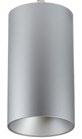
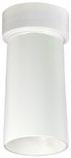
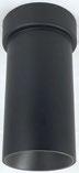
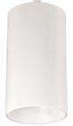
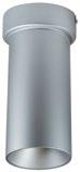
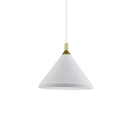
3" iLENE LED Mini Cylinders
PRODUCT DESCRIPTION
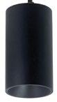
iLENE Series of dedicated LED Mini Cylinders are available in three sizes and outputs, with multiple mounting options. Using Cree® COB technology, the iLENE produces 90+ CRI with excellent cut-off for visual comfort. Each cylinder includes three field-changeable optics for spot, narrow flood and flood (installed) beam spreads.
FEATURES
· 1 500lm / 30W LED
Cree® LED COB or Comfort Dim Technology
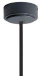
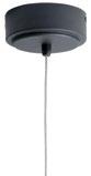
S tem, Surface or Cable Mounted
2 700K, 3000K, 3500K, 4000K or Comfort Dim @ 90+ CRI
F lood (installed), narrow flood and spot optics included
1 20-277V input and Triac, ELV or 0-10V dimming
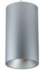
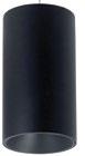
B lack, silver or white cylinder finish
E NERGY STAR® certified
5 -year limited warranty
SPECIFICATION
Construction: Extruded aluminum cylinder with aluminum vented top. Driver is mounted in the canopy to dissipate heat away from the LED module and extend life expectancy.
Reflector: Deep set reflector for minimal aperture brightness. Reflector finish matches cylinder finish.
INSTALLATION (Canopy includes driver & mounts over j-box)
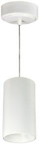
Cable: Cylinder includes 8' field adjustable aircraft cable Surface: Cylinder is connected to canopy and mounts directly over junction box.
Stem: Cylinder can be stem mounted up to 7', must specify stem length (12" increments). Stems are internally threaded and can be connected together, below are configurations included:
Stem LengthStem(s) Included
12" (1') (1) 12" Stem
24" (2') (1) 24" Stem
36" (3')(1) 12" & (1) 24" Stems
48" (4') (2) 24" Stems
60" (5')(2) 24" & (1) 12" Stems
72" (6') (3) 24" Stems
84" (7')(3) 24" & (1) 12" Stems
3" iLENE LED Mini Cylinder with Stem
ELECTRICAL
Input Voltage: 120-277VAC
Lumens / Wattage: 1500lm / 30W (1300lm with Comfort Dim)
Color Temperature: 2700K, 3000K, 3500K or 4000K
Comfort Dim: Comfort Dim color tunes the temperature from a bright 3100K, to a romantic and comfortable 2000K on a gradual, even curve. Comfort Dim delivers up to 1300 lumens.
Color Rendering Index: 90+ CRI
Optics: Three field-changeable optics included Dimming: Triac, ELV or 0-10V
Click Here or check complete dimmer list at www.NoraLighting.com in the “Compatibility” page under “Resources” tab
ACCESSORIES
3" iLENE cylinders accept decorative translucent collars or opaque snoots. Translucent collars color the aperture with the specified color while producing white general light. Opaque snoots greatly reduce aperture brightness while preserving light output. (Note: black snoot will reduce light).
LABELS AND LISTINGS
c ULus Listed for Damp Locations
E NERGY STAR certified
5 -Year Limited Warranty
·C ertified to the high efficacy requirements of California
For over 30 years, TCP has been designing, developing and delivering energy-efficient lighting into the market. Thanks to our cutting-edge technology and manufacturing expertise, we have shipped billions of high quality lighting products. With TCP, you can count on a lighting product that is designed to meet the needs of the market - that transforms your surroundings and envelopes you in warmth - lighting that generates beauty with every flip of the switch.
For over 30 years, TCP has been designing, developing and delivering energy-efficient lighting into the market. Thanks to our cutting-edge technology and manufacturing expertise, we have shipped billions of high quality lighting products. With TCP, you can count on a lighting product that is designed to meet the needs of the market - that transforms your surroundings and envelopes you in warmth - lighting that generates beauty with every flip of the switch.
Sales:
Date:
Model:
Project:
Rep:
Catalog Number: Type: Notes:
CURVANO® 2.5"
Features
Curvano expands on the existing linear slot portfolio of Amerlux, further putting the “arch” in first-class architectural lighting. The 2.5" profile is available in 5 diameter options, as either a curved corner or full 360° circle. With the ability to fit in seamlessly anywhere on your project, from the simplest design to the most complex, Curvano provides infinite design and lighting patterns options: circular, serpentine and rounded-circle displays included. Trust Curvano to provide the freedom to create—and maintain—dynamic, head-turning spaces.
Product Overview
Type: Pendant Direct/Indirect
Wattage: 3W-10W/ft
Max Lumen Output: 7869 lm, 106 lm/W (DL/UC 10W/10W, 4')
Color Temp: 2700K, 3000K, 3500K, 4000K
CRI: 83 or 90+ typ.
Dimming: 0-10V, 1% dimming (standard) Lutron LDE1 Hi-lume® 1% Soft-On/Fade-to-Black DALI dimming, 0.1% dim
Fixture
Summary (see following pages for more information)
4' fixture, electronic multi-volt (120V-277V), constant current LED driver
CURVANO® 2.5"
Curved Linear Direct/Indirect LED
PROJECT: TYPE:
Ordering Information
Model CURV2.5DI
Optic
Direct: Indirect:
DL - designer lens UC - upper clear lens cover BAT - batwing uplight (only available in straight runs)
Mounting
Pendant Mount (aircraft cable suspension)
ASW10 - through ceiling tile or gyp board, white, 10'
ASW20 - through ceiling tile or gyp board, white, 20'
ASB10 - through ceiling tile or gyp board, black, 10'
ASB20 - through ceiling tile or gyp board, black, 20'
ASW10T - over ceiling tee, white, 10'
ASW20T - over ceiling tee, white, 20'
ASB10T - over ceiling tee, black, 10'
ASB20T - over ceiling tee, black, 20'
Mini Cable Suspension - required for D22/D36/D43 ARC & CIR
configurations only
MASW10 - through ceiling tile or gyp board, white, 10'
MASB10 - through ceiling tile or gyp board, black, 10'
MASW10T - over ceiling tee, white, 10'
MASB10T - over ceiling tee, black, 10'
Circuiting
1 - single circuit
2 - up/down switch separately
Wattage (per foot, direct/indirect)
Direct: Indirect:
3 3 4 4 5 5
6
Color Temp-CRI
30 - 3000K-83 279 - 2700K-90+
35 - 3500K-83 309 - 3000K-90+
40 - 4000K-83 359 - 3500K-90+ 409 - 4000K-90+
Consult factory for 90CRI lead time
Finish
HW - high reflectance matte white
BT - black texture
ST - silver texture
Consult factory for other options
Voltage 120/277
Length
_________________ x ______________________ x ________________
Length A Length B Length C
- all patterns - all patterns - PU
- IND - PZ
- CON - CUS
For CIR and ARC configurations, skip to "Diameter & Angle"
Diameter & Angle
D22 - 22" diameter A45 - 45° angle
D36 - 36" diameter A90 - 90° angle
D43 - 43" diameter A135 - 135° angle
D72 - 72" diameter A180 - 180° angle
D100 - 100" diameter CA___ - custom angle
CD___ - custom diameter
______________________ x ______________________ (diameter) (angle)
- ARC - ARC
- CIR
- PLL/PLR
- PLL/PLR - PU
- PU - PZ
- PR - PZ
See page 3 for more detail and restrictions. Patterns with multiple corners to have the same diameter and angle throughout. For IND/ CON/CUS skip to "Configuration."
For jobs with architectural drawings, original CAD file (.DWG) is required to quote.
Configuration
IND - individual straight fixtures, 2' to 8' (in 1' increments)
CON - continuous run, > than 8', specify to nearest foot
CUS - custom made to measure, +/- 1/8" of customer supplied field dimensions
ARC - individual curved fixtures, see diameter and angle options above
CIR - circle (D22, D36, D43 ships assembled; D72, D100 ships in 90° sections)
Standard Patterns (see page 3 for details)
PLL - L left, (2) straight + (1) corner, leg right
Provide overall lengths: A', B' & C'; Diameter & Angle of corners
Example: 4'x10'.D72xA45.PU
PZ - Open Z, (3) straight lengths + (2) corners
Provide overall lengths: A', B' & C'; Diameter & Angle of corners
Example: 12'x6'x10'.D36XA90.PZ
CURVANO® 2.5"
Curved Linear Direct/Indirect LED
PROJECT:
Specifications
Application
Retail and commercial ambient lighting that can be customized with a variety of diameters and angles to create any curved pattern or variety of illuminated circles.
Construction
Extruded aluminum housing. Die-cast End Plates match fixture body finish. Die-formed, cold-rolled steel internal components are protected against rust and corrosion.
Optical
Laser cut acrylic lens, with lift and shift lay-in design. Maximum length is 8’ and maximum angle is 90° (ex. 180° curve will have 2 lenses; Circle will have 4 lenses). All lenses ship installed into fixture. Amerlux’s proprietary acrylic lens provide excellent transmission while effectively concealing source image.
DL – Designer Lens provides flat even glow on lens
UC – Upper Clear Lens cover BAT - Batwing uplight (only available in straight runs)
LED
Amerlux fixtures have excellent thermal management and offer a 5 year warranty. Our LED binning is within 3 MacAdam ellipse. Boards are configured for maximum flexibility resulting in even illumination no matter the fixture layout. LED boards are easily replaced in the field with just a Phillips screw driver.
Color Temperature Options: 2700K, 3000K, 3500K, 4000K
CRI: 83 or 90+ typical
R9: 16 @ CRI 83; >50 @ CRI 90+
Life: 50,000+ hr., > 70% of initial lumens (L70)
Electrical
Wiring: Individual and "Beginning of Run" (BOR) fixtures are prewired with power cord. All configurations have quick connect power harnesses for row connections.
1 - 1 Circuit, direct & indirect same circuit
2 - 2 Circuits, direct & indirect switch separately (power feed at both ends)
Remote Driver Wiring (D22, D36 & D43 ARC or CIR only): Driver is supplied installed in remote driver box, (one driver per box), with 5' of low voltage plenum rated cable. Fixture supplied with 18/2 SJT power cord ready to be connected to J-Box (by others) over cable canopy. Amerlux recommends a maximum of 15' between the fixture and the remote driver box. Consult factory with job specific electrical spec if more than 15' is required. Feeds are added as required by specified wattage and driver maximums. See page 5 for wiring illustration
Standard Wattage: 3-10 W/ft (3W & 4W have a minimum length of 4’). Emergency circuit via remote invert or auxiliary emergency power supply (by others)
This product complies with IEEE C62.41 for surge endurance up to 2 .5KV. Amerlux® recommends using additional surge protection with this unit (supplied by others), surge and over voltage damage is not covered under warranty.
ENLS - Enlighted Sensor (0-10V driver only, not available in 2' & 3' lengths, and can only be used on one circuit). Limited to straight fixtures only.
EMC-PF - Emergency circuit requires power feed to be located in last fixture section for continuous runs. For other locations consult factory. Not available for individual (IND) configuration.
PF - Extra power feed for additional circuiting. Not available for individual (IND) configuration.
EMB - Emergency battery pack - 10W output power, 90 min of illumination time. Illuminated test-switch/charging indicator light is provided. Wattage consumption by EM: 2.5W/ft (4ft fixture), 1.66W/ft (6ft fixture), 1.25W/ft (8ft fixture). Request can be made to light up 4ft section on 8ft unit.
Finish
All painted surfaces are premium powder coated baked on for maximum durability and color stability.
HW - High reflective matte White
BT - Black Texture
ST - Silver Texture
For special paint colors supply RAL and/or actual paint chip for factory consultation.
TYPE:
Configurations/Lengths
IND - Individual straights are standalone fixtures made of single lengths of 2' to 8' (in 1' increments). They are supplied with matching painted End Caps and the required mounting hardware. Lengths less than 4' may have restrictions based upon wattage, lengths, drivers or other options.
CON - Continuous runs are longer than 8', specified to the nearest whole foot. Continuous runs less than 16' are made of 2 lengths. Continuous runs longer than 16' start with a 8' Beginning of Row (BoR) wired with a power feed and fitted with an End Cap. The majority of the runs are made up of 8' Middle of Run (MoR) lengths. End of Run (EoR) units are made up of 2' to 8' units to the nearest whole foot or a combination of a last 4' MoR and a 5', 6' or 7' EoR. Runs longer than 60' may require a second power feed. Factory installed pins and splines simplify fixture alignment. Lengths are quickly joined with "catch and latch" mechanisms or screws and sturdy brackets. Quick connectors simplify field wiring
CUS - Custom made to measure runs are made to nearest 1/8" of customer supplied field measurements. They can be a single custom length or runs configured as described above only EoR's are 2' to 8' cut to the nearest 1/8" exact length or a combination of a last 4' MoR with an EoR cut to exact length to the nearest 1/8".
ARC – Individual arcs are standalone fixtures made of single lengths using a diameter and an angle (ex. D43 x A90 is a 4’ diameter, 90° individual fixture). They are supplied with matching painted End Caps and the required mounting hardware. All diameters utilize a remote mounted driver.
CIR – Circle fixtures made up of a single housing (D22, D36 & D43) or shipped in 90° segments (D72, D100). All diameters utilize a remote mounted driver. PLL/PLR/PR/PU/PZ - Standard patterns consist of standard diameter & angle corners with standard lengths (3' to 8' in 1' increments) or custom lengths. Patterns with multiple corners will have the same diameter and angle utilized throughout the pattern. Depending upon complexity of the pattern, drawings may be required. When ordering please give overall lengths. See page 3 for layouts.
PC - Custom patterns use standard or custom lengths, 90º or other corner angles with some limitations. Please provide drawings and consult factory
Mounting
For indirect lighting Amerlux suggests 18" min from top of fixture to ceiling. Standard or custom patterns available.
CURV2.5DI....ASW10 - Direct/Indirect installed in center of ceiling tile or gypsum board ceiling, (standard) i.e. ASW10. Or if canopy is installed on a grid Tee runner add, T i.e. ASW10T.
Cable Suspension: Cable is stranded stainless steel wire supplied with cable gripper and 5"x .250" steel die formed canopy. All components are protected against rust and corrosion. Power feeds are 16 gauge 3 or 5 conductor SJT cord supplies in same color as canopy. Amerlux supplies the required feed and non-feed suspension kits based upon length, electrical options and customer requirements. Suspension kit options include: color, length and mounting condition.
Mini Cable Suspension: 5" diameter by 0.25" canopy is used for both feed and non-feed Mini Cable Kits. The thinner Low Voltage power feeds are 22 gauge 2 conductor SJT cords supplied in same color as canopy. Amerlux supplies the required feed and non-feed suspension kits based upon length, electrical options and customer requirements. Suspension kit options include: color and mounting condition.
Please note: 1 Circuit is standard, the direct & indirect are on the same circuit. 2 Circuits, direct & indirect switched separately with power feeds at both ends.
Certifications
Approved to UL standards as tested by CSA. Intended for indoor use only
Warranty
Amerlux's 5 year limited warranty. Please consult Amerlux website for details.
CURVANO® 2.5"
Curved Linear Direct/Indirect LED
PROJECT:
TOOLLESS JOINING
Line up the two housings by using the alignment pins & splines. Secure them together by using the Catch & Latch System on the top of or inside the extrusion.
D22/36/43 ARC & CIR configurations only
Note: Driver required for every 4'. Remote drivers can be installed up to 15' max from fixture.
LENS INSTALL/REMOVAL
CURVANO® 2.5"
Curved Linear Direct/Indirect LED
PROJECT: TYPE:
RUN LENGTHS AND DIMENSIONS (View from top of fixture. Black dots represent mounting points)
piece Cable Coupler Gripper/Locknut (size will vary)
TEE GRID OR SCREW SLOT (ASW10T, ASW20T, ASB10T, ASB20T, MASW10T, MASB10T) FEED NON-FEED
Drop Ceiling J-Box (supplied) Cat# Length Cord/Canopy Application
Drop Ceiling T-Bar by others (for Drop Ceiling application) Drop Ceiling T-Bar by others
Canopy J-Box secured to structure above by others
IDS Clip with 1/4"-20 Stud by others
CURVANO® 2.5"
Curved Linear Direct/Indirect LED
PROJECT:
FIXTURE DATA: (Complete photometric data (.ies format) available upon request)
MULTIPLYING FACTORS:
CURVANO® 2.5"
FIXTURE DATA: (Complete photometric data (.ies format) available upon request)
MULTIPLYING FACTORS: (Multiplying
CURVANO® 2.5"
Curved Linear Direct/Indirect LED
PROJECT:
DIMMING COMPATIBILITY:
TYPE:
Amerlux® Curvano® fixtures are compatible with all major dimming protocols prevalent in the United States. Please see below for general compatibilities and wiring diagrams. Amerlux recommends testing your unique dimming configuration as the exact full configuration (Dimmer, Fixture Quantity, Voltage, etc) may affect dimming performance.
--- NOTE: INFORMATION BELOW IS FOR WIRED DIMMERS ONLY. FOR WIRELESS DIMMERS,
0-10V - DIMMING (Standard)
Integrates into a variety of building management and daylighting controls
Notes:
• 120V or 277V*
• Dims down to 1% light output
• Requires interface to turn off power to driver
• Consult Dimming manufacturer for installation instructions - DO NOT SHARE NEUTRALS!
Compatible Dimmers†:
Wall Box
Lutron: Wattstopper: Leviton:
Diva - DVSTV ADF-120277 Renoir II
Maestro - MS-Z101
Nova-T - NTSTV-DV
Center System
Lutron Grafixk Eye with GRX-TV1 Interface
LUTRON LDE1 DIMMING
Integrates into Lutron EcoSystem building management
Notes:
• 120VAC or 277VAC*
• Dims down to 1% Soft-On/Fade-to-Black
• EcoSystem Control
• Consult Dimming manufacturer for installation instructions - DO NOT SHARE NEUTRALS!
Compatible Dimmers†:
Lutron ECO System
Pow Pak Dimming Modules
Energi Savr Node
Grafik Eye QS/Homeworks
QS Control Unit
Quantum Hub
Homeworks QS/My Room
DALI - DALI DIMMING 120V-277V
Central System
Lutron EcoSystem compatible controls
Digital control protocol allows individual fixture control
Notes:
• 120V - 277V*
• Dims down to 0.1% light output in most cases
Compatible Dimmers†: Wall Box
Leviton CD250 Controller
Center System
Dynalite
Fifth Light
Notes:
* Driver is 277V dimmable with appropriate dimmer (by others). All
dimmer installation instructions for 277V wiring diagrams.
0-10V Wiring Diagram
Lutron LDE1 (HILUME-H-ECO) EcoSystem Digital Control Wiring Diagram
Wiring Diagram
† The absence of a dimmer from the lists above does not imply incompatibility. Please consult factory for compatibility inquiries.
Carisma 2"
Linear Direct/Indirect LED
PROJECT:
Features
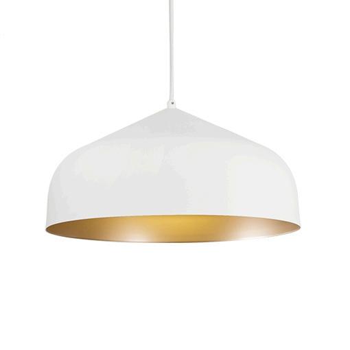
Carisma Pendant is part of a family of architectural linear luminaires that offer excellent performance, quality, visuals and value. A sleek edge-to-edge lens design results in an elegant aesthetic with clean lines. Carisma’s patent pending design includes an integrated optical system that minimizes optical losses, allowing for industry-leading efficacy that meets the stringent requirements for DLC Listing (DLC Listing pending). A tailored end cap design and Amerlux’s trusted catch-and-latch mechanism prevents all light leakage.
The Carisma Pendant offers luminaires with 2” and 3" wide apertures, delivering seamless lighting as discrete individual fixtures, continuous rows or patterns. Carisma can be specified to the nearest 1/8” and is available in pendant, surface, wall and recessed mounting options, providing designers with the versatility to light up a space with their Carisma.
Product Overview
Type:
Direct/Indirect distribution with Pendant or Wall Mounting Performance lens down/Batwing lens up
Wattage: 5W/ft, 10W/ft (or specify both direct & indirect wattage each between 3W/ft and 10W/ft)
Color Temp: 2700K*, 3000K, 3500K, 4000K (* 90+ CRI only)
CRI: 80+ or 90+
Dimming (wired): 0-10V, 1% dimming (standard) Lutron LDE1 Hi-lume® 1% Soft-On/Fade-to-Black DALI dimming, 1% dim
EMC-PF2 - emergency circuit requires power feed located in last fixture section (for other locations consult factory)
PF2 - Extra power feed for additional circuiting
EMB* - emergency battery pack (not available for lengths under 4')
Carisma 2” Direct/Indirect
Linear Direct/Indirect LED
PROJECT:
Specifications
Construction
Extruded aluminum housing and reflector. Die-cast end caps match fixture body finish.
Weight: 2.5 lbs/ft (may vary based on configurations and accessories)
Optical
Direct:
All Direct lenses are snap-in, extruded acrylic, with a maximum length of 8'. Amerlux's proprietary acrylic lens provides excellent transmission while effectively concealing source image.
PL - Performance lens provides high efficiency with controlled lens surface brightness.
ASY - Asymmetric throw lens.
Indirect:
Extruded acrylic lens with a maximum length of 4’.
BAT- Batwing uplight lens spreads light directly above fixture. A minimum of 18" distance between ceiling plane and top of fixture is suggested.
LED
Our LED binning is within 3 MacAdam ellipse. Boards are configured for maximum flexibility resulting in even illumination no matter what the fixture layout. LED boards are easily replaced in the field with just a Phillips screw driver.
Color Temperature Options: 2700K*, 3000K, 3500K, 4000K
CRI: 80+, 90+
R9: 16 @ CRI 83; R9: >50 @ CRI 92
Life: 50,000+ hr., > 70% of initial lumens (L70)
* Available in 90+ CRI only
Electrical
Wiring: Individual and "Beginning of Run" (BOR) fixtures are prewired with power cord. All configurations have quick connect power harnesses for row connections.
1 - Single Circuit, direct & indirect are on the same circuit
2 - Dual Circuits, direct & indirect controlled independently
Standard Wattage: 5W/ft, 10W/ft.
Optional Wattages: 3W/ft, 4W/ft, 6W/ft, 7W/ft, 8W/ft, 9W/ft. (3W & 4W have a minium length of 4'). For other wattages consult factory. Emergency circuit via remote inverter or auxiliary emergency power supply (by others).
This product complies with IEEE C62.41 for surge endurance up to 2.5KV. Amerlux® recommends using additional surge protection with this unit (supplied by others), surge and over voltage damage is not covered under warranty.
EMC-PF - Emergency circuit requires power feed to be located in last fixture section for continuous runs. For other locations consult factory. Not available for individual (IND) configuration.
PF - Extra power feed for additional circuiting. Not available for individual (IND) configuration.
Finish
All painted surfaces are premium powder coated baked on for maximum durability and color stability.
HW - High reflective matte White
BT - Black Texture
ST - Silver Texture
For special paint colors supply RAL and/or actual paint chip for factory consultation.
TYPE:
Configurations/Lengths
Straights:
IND - Individual fixtures are made of single standard lengths of 2 ft to 8 ft (in 1' increments). These are stand alone fixtures with matching End Caps, supplied with the mounting hardware. Lengths less than 4' may have restrictions based upon wattage, lengths, drivers or other options.
CON - Continuous runs, > 8' specified to nearest whole foot length in 1' increments. Runs made from standard lengths have End Caps at the beginning and end of run. Runs > 60' may require second power feed. Each housing has factory installed alignment pins. Mating fixtures are easily aligned and joined. Wiring is made fast and positive with molded quick connectors.
CUS - Custom made to measure runs are made to nearest 1/8"of customer supplied field measurements or drawings. Custom lengths use the same hardware for hairline joining.
Patterns:
PXX- Standard Patterns consist of 90º corners with standard lengths (4' to 8' in 1' increments), continuous runs or made to measure lengths. Depending upon complexity of the pattern drawings may be required from the customer. If ordering please give overall lengths.
A'-B'-PLL - L Left - (1) 90º Corner 2 segments. Specify overall segments:
A’ & B’
A'-B'-PLR - L Right - (1) 90º Corner 2 segments. Specify overall segments:
The Carisma Direct/Indirect is intended for pendant or wall mounting. For even lighting on ceiling, Amerlux suggests 18" minimum distance from top of fixture to ceiling when pendant mounted.
Pendant Mount-ASWxx - Direct/Indirect pendant mounted in center of ceiling tile or gypsum board ceiling (standard) i.e. ASWxx. Or if canopy is installed on a grid Tee runner add, T i.e. ASWxxT.
Cable is stranded stainless steel wire. All fittings are protected against rust and corrosion. Canopies are 5" x 1/4" die formed painted steel. Adjustment mechanism allows for infinite height adjustment. Amerlux recommends the required feed and non-feed suspensions based upon length and electrical options. Options include: color of canopy and power cord (black or white), length 4', 10' or 20', and mounting condition, in center of ceiling tile and in gypsum board ceiling (standard) i.e. ASWxx. Or if canopy is installed on a grid Tee runner add, T i.e. ASWxxT
Wall Mount-WM - Direct/Indirect wall mounted using steel cleat bracket attached to fixture housing and wall bracket with set screws. Two bracket assemblies are used for each length. A third center bracket may be recommended. J-box required at feed locations.
Please note: Single Circuit is standard, the direct & indirect are on the same circuit. For Dual Circuits, direct & indirect are controlled independently.
Options
EMB - Emergency battery pack - 10W output power, 90 min of illumination time, up to 1300 lm of initial light output. Illuminated test-switch/charging indicator light is provided. Wattage consumption by EM: 2.5W/ft (4ft fixture), 1.25W/ft (8ft fixture). Request can be made to light up 4ft section on 8ft unit.
Certifications
Approved to UL standards for damp locations as tested by CSA
Intended for indoor use only
DLC Listing pending
Warranty
Amerlux's 5 year limited warranty. Please consult Amerlux website for details.
Carisma 2” Direct/Indirect
Linear Direct/Indirect LED
PROJECT:
Pendant
TOOLLESS JOINING
Line up the two housings using the alignment brackets. Secure them together by using the Catch & Latch System on the top of the extrusion.
Carisma
Carisma 2” Direct/Indirect
Linear Direct/Indirect LED
CEILING OR GYPSUM BOARD (ASW04, ASW10, ASW20, ASB04, ASB10, ASB20)
TEE GRID OR SCREW SLOT (ASW04T, ASW10T, ASW20T, ASB04T, ASB10T, ASB20T)
Carisma 2” Direct/Indirect
Linear Direct/Indirect LED
PROJECT: TYPE:
OPTIONAL SENSOR/RF NODE:
Amerlux® has partnered with control companies to create building environments that are safer and smarter, than ever before. At the heart of our partnership is intelligent RF nodes and Smart Sensor, the most advanced digital wireless communication and sensors available today. Integrated into Amerlux products.
Minimum run length is 3' for wireless sensor and RF node.
INDIVIDUAL (MIN 3' LENGTH)
Optional Enlighted Sensor
CARISMA 2" PATTERNS:
Standard Patterns
All corners are standard 90°, standard length legs. Use standard lengths: 4' min to 8' in 1 foot increments.
Continuous runs must be the same length in pairs for closed configuration.
PLL - L Left, (2) straights + (1) 90° corner, leg right
PLR - L Right, (2) straights + (1) 90° corner, leg left
Provide overall lengths: A', B' & C' Nomenclature: A-B-C-PZ
Carisma 2” Direct/Indirect
Carisma 2” Direct/Indirect
Linear Direct/Indirect LED
FIXTURE DATA:
MULTIPLYING FACTORS: (Multiplying Factor is
Source: 384 White LED's
Source:
2”
Carisma 2” Direct/Indirect
Linear Direct/Indirect LED
PROJECT: TYPE:
DIMMING COMPATIBILITY:
Amerlux® Carisma fixtures are compatible with all major dimming protocols prevalent in the United States. Please see below for general compatibilities and wiring diagrams. Amerlux recommends testing your unique dimming configuration as the exact full configuration (Dimmer, Fixture Quantity, Voltage, etc) may affect dimming performance.
--- NOTE: INFORMATION BELOW IS FOR WIRED DIMMERS ONLY. FOR WIRELESS DIMMERS, CONSULT FACTORY ---
0-10V - DIMMING (Standard)
Integrates into a variety of building management and daylighting controls
Notes:
• 120VAC or 277VAC*
• Dims down to 1% light output
• Requires interface to turn off power to driver
• Consult Dimming manufacturer for installation instructions - DO NOT SHARE NEUTRALS!
Compatible Dimmers†: Wall Box
Lutron: Wattstopper: Leviton:
Diva - DVSTV ADF-120277 Renoir II
Maestro - MS-Z101
Nova-T - NTSTV-DV
Center System
Lutron Grafixk Eye with GRX-TV1 Interface
LUTRON LDE1 DIMMING
Integrates into Lutron EcoSystem building management
Notes:
• 120VAC or 277VAC*
• Dims down to 1% Soft-On/Fade-to-Black
• EcoSystem Control
• Consult Dimming manufacturer for installation instructions - DO NOT SHARE NEUTRALS!
Compatible Dimmers†:
Lutron ECO System
Pow Pak Dimming Modules
Energi Savr Node
Grafik Eye QS/Homeworks
QS Control Unit
Quantum Hub
Homeworks QS/My Room
Notes:
Central System
Lutron EcoSystem compatible controls
0-10V Wiring Diagram
* Driver is 277VAC dimmable with appropriate dimmer (by others). All provided wiring diagrams show 120VAC wiring colors and method. Please refer to 277VAC dimmer installation instructions for 277VAC wiring diagrams.
† The absence of a dimmer from the lists above does not imply incompatibility. Please consult factory for compatibility inquiries.
Lutron LDE1 (HILUME-H-ECO) EcoSystem Digital Control Wiring Diagram
Carisma 2” Direct/Indirect
Linear Direct/Indirect LED
PROJECT: TYPE:
DIMMING COMPATIBILITY:
Amerlux® Carisma fixtures are compatible with all major dimming protocols prevalent in the United States. Please see below for general compatibilities and wiring diagrams. Amerlux recommends testing your unique dimming configuration as the exact full configuration (Dimmer, Fixture Quantity, Voltage, etc) may affect dimming performance.
--- NOTE: INFORMATION BELOW IS FOR WIRED DIMMERS ONLY. FOR WIRELESS DIMMERS, CONSULT FACTORY ---
DALI - DALI DIMMING 120V-277V
Digital control protocol allows individual fixture control
Notes:
• 120VAC - 277VAC*
• Dims down to 1% light output in most cases
Compatible Dimmers†: Wall Box
Leviton CD250 Controller
Center System
Dynalite Fifth Light
DALI Wiring Diagram
EMERGENCY FIXTURE WITH BUILT-IN BATTERY PACK (EMB) WIRING:
Note: EMB not available on lengths under 4'.
EMERGENCY DRIVER
Notes:
* Driver is 277VAC dimmable with appropriate dimmer (by others). All provided wiring diagrams show 120VAC wiring colors and method.
Please refer to 277VAC dimmer installation instructions for 277VAC wiring diagrams.
† The absence of a dimmer from the lists above does not imply incompatibility. Please consult factory for compatibility inquiries.
LR25178
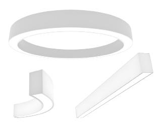
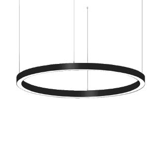
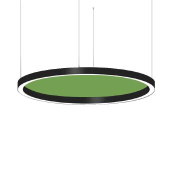
(VRD) Vicky Ring Downward Light Acoustic Light
The Vicky Ring light is a unique ring style light with an LED light source illuminating downward. It is available in sizes ranging from 23.6”(dia.) up to 196.9”(dia.) . This design features aluminum body construction and an optional acoustic system that maximizes surface area to absorb sound waves and improve harmony in the installed space, providing a perfect integration of lighting and acoustic control.
FEATURE
• Fixtures in diameters from 23.6" through 196.9"
• Available in standard light and acoustic w/light.
• Direct illuminating
30+ acoustic felt colors available
SPECIFICATION
and wire cord length: 59" (1.5m)
ELECTRICAL SYSTEM
• Input Voltage: 120-277V, 50/60Hz
• 0-10V Dimming standard
• Minimum Ambient -20˚C, Maximum Ambient is 40˚C
Power Factor: > 0.9 at full load
• Total Harmonic Distortion: < 20% at full load
Dimming 0-10V Dimming Standard
• cETLus conforms to
• Suitable for dry locations
• RoHs compliant
DIMENSION
23.6"(600mm)10.0"(250mm)
Section QuantityWattage Driver Quantity
Ordering Information
- Vicky Ring
1. Series D - Downward Light
3. Acoustic Configuration
2. Light Emitting Blank- Light without Acoustic LA - Light with Acoustic
* If choose Acoustic, please choose the acoustic color in the following list. Acoustic is not available for 100W, 120W, 160W, 200W, 300W and 400W.
Notes;
1. Acoustic is not available for 100W, 120W, 160W, 200W, 300W and 400W.
2. 120W, 160W, 200W, 300W and 400W are shipped in sections and need to be installed in the field.
5. CCT
30 - 3000K
40 - 4000K
6. CRI
90 - 90Ra
7. Voltage
1 - 120-277V
8. Installation
ACPMK - Aircraft Cable Pendant Mount Kits*
35 - 3500K
50 - 5000K
9. Controls
Blank - None
10. Frame Finish
WH - White
* White finish frame is standard. Custom colors might be available for an additional fee. Please check with Customer Service for more information
SMK - Surface Mount Kits
* Centural canopy pendant is standard for 40W/50W/80W/100W. Direct suspended is standard for 120W/160W/200W/300W/400W.
Acoustic Color
* There will be slight differences between the color of the acoustic image and the actual fabric because of computer display defects.
* The standard acoustic colors include: NSAC-021 130, NSAC-042 146, NSAC-028 110, NSAC-002 122, NSAC-033 103. Other acoustic colors might be available for an additional fee. Please check with Customer Service for more information
PHOTOMETRY
All published luminaire photo metric testing performed to IESNA LM-79-08 standards by a NVLAP certified laboratory. IESNA LM -79-08 specifies the entire luminaire as the source resulting in a fixture efficiency of 100%.Result may vary per actual order.
PERFORMANCE DATA
Lumen values are measured by third party certified laboratories performed in accordance with IESNA LM-79-08 as well as Lighting Facts listed.
Note:
1. The lumen output is for the fixture without acoustic.The data for acoustic may vary based on different acoustic fiber colors. Please contact Customer Service if need the lumen output for acoustic version. 2. Lumen outputs for 100W/120W/160W/200W/300W/400W are calculated.
Five year limited warranty.
Notes: Specifications subject to change without notice.
ALUMINUM MOUNTING CHANNEL ®
4’ / 8’ WIDE FORMAT
PRODUCT OVERVIEW
GM Lighting’s LED-CHL-W channel accepts all low voltage
GM Lighting LED tape. Available in 48” and 96” lengths, these wide format mounting channels are the perfect vessel that not only insures an architectural quality installation, but also minimizes diode imaging due to the frosted lens that is included with each channel.
FEATURES
•Available in 4ft (48in) and 8ft (96in)
• Silver Anodized finish
•Includes 2 mounting clips and screws with 4ft, 4 mounting clips and screws with 8ft
•Includes acrylic frosted lens
•End caps sold separately
• For LTR Series Tape - LTR-P, LTR-S and LTR-E
• Custom lengths available - consult factory
•Dry location only
Note: For Vision120, use V120-CHL channels.
SPECIFICATIONS
ELECTRICAL
•Fits 12V/24V LEDtask LED tape
WARRANTY
•5-year warranty
ALUMINUM MOUNTING CHANNEL ®
4’ / 8’ WIDE FORMAT
LED-CHL-W
LED-CHL-W-8
DIAGRAM
DIMENSIONS
L48”or 96” x W 1.019” x D.457”
Sure-Tite and EZ Connectors LTR-P, LTR-S, LTR-E Series Dry and Wet Location Blank (Silver Anodized)
/ 96”
Magnetic Dimmable ®
12/24VDC LineDRIVE Power Supply
Specification Sheet
PRODUCT OVERVIEW
LED dimming magnetic power supply that works with conventional low voltage magnetic wall mount dimmer with on/off switch. 12 or 24 VDC output. 120 or 277 VAC input. Highest efficiency with auto reset. Compatible with standard low voltage magnetic dimmers. Not recommended for digital control systems.
FEATURES
• Multi-tap Class 2
• 120VAC and 277VAC dual input
• Auto-reset protection for short circuit
• NEMA 3R enclosure with built-in junction box
• Fanless design, cooling by free air convection
• Dimmable with compatible MLV dimmers
• Suitable indoor/outdoor wet locations when mounted vertically
• Load: min. 20% to max. 80% for optimal performance
HOUSING
• Black powder coated steel enclosure
• Cooling by free-air convection ENVIRONMENT
• Outdoor / wet location NEMA 3R enclosure. For vertical mounting only.
ORDERING INFORMATION
OPERATING TEMP
• 0 to 104°F (-18 to +40°C)
CERTIFICATION
• ETL compliant
• Cert. CSA C22.2 No. 250.2
• Class 2
WARRANTY
• 5-year warranty
Magnetic Dimmable ®
12/24VDC LineDRIVE Power Supply
Specification Sheet
DIMENSION
LD-MD-UNV30
LD-MD-UNV60
LD-MD-UNV96-24
LD-MD-UNV150-12
LD-MD-UNV200-24
LD-MD-UNV300-24
Magnetic Dimmable ®
12/24VDC LineDRIVE Power Supply
Specification Sheet
WIRING DIAGRAMS
SINGLE CHANNEL DIAGRAM
30W, 60W, 96W
NOTE: The following diagrams are provided as example system designs. Install in accordance with national and local electrical code regulations.
MULTI CHANNEL DIAGRAM
150W, 200W, 300W
*Connect the male DC plug to either the 12V or 24V female plug depending on your output voltage. **Connect the male AC plug to either 120VAC or 277VAC female plug depending on your input voltage.
LTR-P Professional Series
3W, 12VDC and 24VDC LED Tape Specification Sheet
PRODUCT OVERVIEW
GM’s Professional Series Flexible LED Tape combines style and technology with reliability. Designed for professional installations that demand a high level of quality, the LTR-P Series includes a wide array of key features and is available in 16’-4” (5M) and 100’ (30M) reels.
FEATURES
• 12VDC or 24VDC models
• 2400K, 2700K, 3000K, 3500K, 4000K and 5000K color temps
• Remote control with GM’s LUXcontrol™ App and controllers
• Dry location
• 120 LEDs per meter
• Cuttable every 2”
• Custom lengths available - consult factory
• Premium diodes
• 120° viewing angle
• Dimmable
• 3M adhesive back
• Maximum run on a given lead is 16’-4”(12V) and 32’-8”(24V)
• Includes Sure-Tite connectors
SPECIFICATIONS
ELECTRICAL
• 12V/24V
• 3 watts per foot
OPTICS
• 90+ CRI
-4F to 122 F
TEMP
LTR-P Professional Series ®
3W, 12VDC and 24VDC
LED Tape Specification Sheet
LTR-P-24V-3W-40K-16
/
/
/
/
Kelvin temperature (color) ±100K. 16’-4” and 100’ reel includes 48” lead affixed to tape. 16’-4” reel includes (3) ESTW-60 Sure-Tite connectors. 100’ reel includes (10) ESTW-60 Sure-Tite connectors
COMPATIBLE CONTROLLERS
Model Description
SHWC LUXcontrol Smart 2.4 GHz WiFi Controller, Standard 12V/24V Low Voltage, see page 8
SHWD LUXcontrol Smart 2.4 GHz WiFi Dimmer, Standard 12V/24V Low Voltage, see page 8
SWD-40W-12VDC-DIM SwitchLD All-in-One Dimmer and Driver, 40W, 12VDC see page 10
SWD-60W-12VDC-DIM SwitchLD All-in-One Dimmer and Driver, 60W, 12VDC see page 10
SWD-60W-24VDC-DIM SwitchLD All-in-One Dimmer and Driver, 60W, 24VDC see page 10
SWD-100W-24VDC-DIM SwitchLD All-in-One Dimmer and Driver, 100W, 24VDC see page 10
LTR-P Professional Series ®
3W, 12VDC and 24VDC
LED Tape Specification Sheet
RECOMMENDED DRIVERS
LD-XD-UNV LineDrive Electronic Multi-Dimmable Power Supply, 12VDC or 24VDC 20W, 40W, 60W, 96W, 180W, 200W, 300W
LD-E-UNV LineDrive Electronic Non-Dimmable Power Supply, 12VDC or 24VDC 30W, 60W, 96W, 200W, 300W
LD-MD-UNV LineDrive Magnetic Dimmable Power Supply, 12VDC or 24VDC 30W, 60W, 96W, 150W, 200W, 300W
LD-EDM LineDrive Electronic Dimmable MINI Power Supply, 12VDC or 24VDC 60W
LTP Cord and Plug Power Supply, 12VDC or 24VDC 25W, 48W, 60W, 90W
PSD Electronic Dimmable Power Supply, 12VDC or 24VDC 15W, 24W, 60W, 90W
DIMENSION
(1mm) Cuttable every 2” (51mm)
SERIES
CONNECTORS
LTR-P Professional Series ®
3W, 12VDC and 24VDC
LED Tape Specification Sheet
LED-CHL-XD
Extra deep format extruded channel. Includes snap-on frosted lens with mounting clips and screws. 4’
LED-CHL-XD-8 Extra deep format extruded channel. Includes snap-on frosted lens with mounting clips and screws. 8’
LED-CHL-XD-AMC (2) Adjustable mounting brackets for LED-CHL-XD N/A
LED-CHL-XD-EC (2) End caps for LED-CHL-XD. One solid, one with hole. N/A
LED-CHL-XD-MC (2) Mounting clips and screws for LED-CHL-XD N/A
LED-CHL-XD-F
LED-CHL-XD-F-8
Extra deep format extruded channel with flange. Includes snap-on frosted lens with mounting clips and screws. 4’
Extra deep format extruded channel with flange. Includes snap-on frosted lens with mounting clips and screws. 8’
LED-CHL-XD-F-DC (2) Drywall mounting brackets for LED-CHL-XD-F N/A
LED-CHL-XD-F-EC (2) End caps for LED-CHL-XD-F. One solid, one with hole. N/A
LED-CHL-XD-MD Mini deep format extruded channel. Includes snap-on frosted lens with mounting clips and screws. 4’
LED-CHL-XD-MD-WH Mini deep format extruded channel. Includes snap-on frosted lens with mounting clips and screws. White. 4’
LED-CHL-XD-MD-B
LED-CHL-XD-MD-8
Mini deep format extruded channel. Includes snap-on frosted lens with mounting clips and screws. Black. 4’
Mini deep format extruded channel with flange. Includes snap-on frosted lens with mounting clips and screws. 8’
LED-CHL-XD-MD-8-WH Mini deep format extruded channel. Includes snap-on frosted lens with mounting clips and screws. White. 8’
LED-CHL-XD-MD-8-B Mini deep format extruded channel. Includes snap-on frosted lens with mounting clips and screws. Black. 8’
LED-CHL-XD-MD-AMC (2) Adjustable mounting brackets for LED-CHL-XD-MD N/A
LED-CHL-XD-MD-EC (2) End caps for LED-CHL-XD-MD. One solid, one with hole. N/A
LED-CHL-XD-MD-MC (2) Mounting clips for LED-CHL-XD-MD N/A
LED-CHL-XD-MD-F Mini deep format flanged extruded channel with flange. Includes snap-on frosted lens with mounting clips and screws. 4’
LED-CHL-XD-MD-F-WH Mini deep format flanged extruded channel with flange. Includes snap-on frosted lens with mounting clips and screws. White. 4’
LED-CHL-XD-MD-F-B Mini deep format flanged extruded channel with flange. Includes snap-on frosted lens with mounting clips and screws. Black. 4’
LED-CHL-XD-MD-F-8 Mini deep format extruded flanged channel with flange. Includes snap-on frosted lens with mounting clips and screws. 8’
LED-CHL-XD-MD-F-8-WH Mini deep format extruded flanged channel with flange. Includes snap-on frosted lens with mounting clips and screws. White. 8’
LED-CHL-XD-MD-F-8-B Mini deep format extruded flanged channel with flange. Includes snap-on frosted lens with mounting clips and screws. Black. 8’
LED-CHL-XD-MD-F-DC (2) Drywall mounting brackets for LED-CHL-XD-MD-F
N/A
LED-CHL-XD-MD-F-EC (2) End caps for LED-CHL-XD-MD-F One solid, one with hole. N/A
MINI DEEP
LTR-P Professional Series ®
3W, 12VDC and 24VDC LED Tape Specification Sheet
COMPATIBLE CHANNELS- FIT CONNECTORS ON PG. 1
LED-CHL-45 Extruded angled (45°) channel. Includes snap-on frosted lens with mounting clips and screws. 4’
(2) End caps for LED-CHL-45 - one solid, one with hole
(2) Mounting clips and screws for LED-CHL-45
Extruded angled (45°) channel. Includes snap-on frosted lens with mounting clips and screws.
(2) End caps for LED-CHL-45 - one solid, one with hole
(2) Additional mounting clips for LED-CHL-45-1200
Wide format extruded
- one solid, one with hole.
(2) End caps for LED-CHL-MI-ST8 one solid, one with hole.
COMPATIBLE CHANNELS - SOLDERED LEADS ONLY
LED-CHL Extruded channel. Includes snap-on frosted lens with mounting clips and screws.
LED-CHL-8 Extruded channel. Includes snap-on frosted lens with mounting clips and screws.
(2) Adjustable mounting brackets for LED-CHL
(2) End caps for LED-CHL - one solid, one with hole.
(2) Additional mounting clips for LED-CHL
LTR-P Professional Series ®
3W, 12VDC and 24VDC LED Tape Specification Sheet
SHWC LUXCONTROL WIFI CONTROLLER
N G
LineDrive LD-E Series Non Dimmable Power Supply
SHWC CONTROLLER
GROUP MULTIPLE CONTROLLERS IN THE LUXCONTROL APP
12V or 24V LED TAPE
LineDrive LD-E Series Non Dimmable Power Supply
SHWC CONTROLLER
N G L N G
LineDrive LD-E Series Non Dimmable Power Supply
SHWC CONTROLLER
12V or 24V LED TAPE
12V or 24V LED TAPE
LTR-P
LTR-P
LTR-P
LTR-P Professional Series ®
3W, 12VDC and 24VDC
LED Tape Specification Sheet
SHWC LUXCONTROL WIFI CONTROLLER WITH POWER REPEATER
LineDrive LD-E Series Non Dimmable Power Supply
LineDrive LD-E Series Non Dimmable Power Supply SHWC CONTROLLER
SHWC-RGBW-RPT REPEATER
LineDrive LD-E Series Non Dimmable Power Supply
SHWC-RGBW-RPT REPEATER
LTR-P 12V or 24V LED TAPE LTR-P 12V or 24V LED TAPE
SHWC-RGBW-RPT REPEATER
LineDrive LD-E Series Non Dimmable Power Supply TO ADDITIONAL REPEATERS AND POWER SUPPLIES
LTR-P
LTR-P Professional Series ®
3W, 12VDC and 24VDC
LED Tape Specification Sheet
LTR-P 12V or 24V LED TAPE
12V or 24V
TAPE
LTR-P 12V or 24V LED TAPE
ALUMINUM MOUNTING CHANNEL ®
4’ / 8’ WIDE FORMAT
PRODUCT OVERVIEW
GM Lighting’s LED-CHL-W channel accepts all low voltage
GM Lighting LED tape. Available in 48” and 96” lengths, these wide format mounting channels are the perfect vessel that not only insures an architectural quality installation, but also minimizes diode imaging due to the frosted lens that is included with each channel.
FEATURES
•Available in 4ft (48in) and 8ft (96in)
• Silver Anodized finish
•Includes 2 mounting clips and screws with 4ft, 4 mounting clips and screws with 8ft
•Includes acrylic frosted lens
•End caps sold separately
• For LTR Series Tape - LTR-P, LTR-S and LTR-E
• Custom lengths available - consult factory
•Dry location only
Note: For Vision120, use V120-CHL channels.
SPECIFICATIONS
ELECTRICAL
•Fits 12V/24V LEDtask LED tape
WARRANTY
•5-year warranty
ALUMINUM MOUNTING CHANNEL ®
4’ / 8’ WIDE FORMAT
LED-CHL-W
LED-CHL-W-8
DIAGRAM
DIMENSIONS
L48”or 96” x W 1.019” x D.457”
Sure-Tite and EZ Connectors LTR-P, LTR-S, LTR-E Series Dry and Wet Location Blank (Silver Anodized)
/ 96”
Magnetic Dimmable ®
12/24VDC LineDRIVE Power Supply
Specification Sheet
PRODUCT OVERVIEW
LED dimming magnetic power supply that works with conventional low voltage magnetic wall mount dimmer with on/off switch. 12 or 24 VDC output. 120 or 277 VAC input. Highest efficiency with auto reset. Compatible with standard low voltage magnetic dimmers. Not recommended for digital control systems.
FEATURES
• Multi-tap Class 2
• 120VAC and 277VAC dual input
• Auto-reset protection for short circuit
• NEMA 3R enclosure with built-in junction box
• Fanless design, cooling by free air convection
• Dimmable with compatible MLV dimmers
• Suitable indoor/outdoor wet locations when mounted vertically
• Load: min. 20% to max. 80% for optimal performance
HOUSING
• Black powder coated steel enclosure
• Cooling by free-air convection ENVIRONMENT
• Outdoor / wet location NEMA 3R enclosure. For vertical mounting only.
ORDERING INFORMATION
OPERATING TEMP
• 0 to 104°F (-18 to +40°C)
CERTIFICATION
• ETL compliant
• Cert. CSA C22.2 No. 250.2
• Class 2
WARRANTY
• 5-year warranty
Magnetic Dimmable ®
12/24VDC LineDRIVE Power Supply
Specification Sheet
DIMENSION
LD-MD-UNV30
LD-MD-UNV60
LD-MD-UNV96-24
LD-MD-UNV150-12
LD-MD-UNV200-24
LD-MD-UNV300-24
Magnetic Dimmable ®
12/24VDC LineDRIVE Power Supply
Specification Sheet
WIRING DIAGRAMS
SINGLE CHANNEL DIAGRAM
30W, 60W, 96W
NOTE: The following diagrams are provided as example system designs. Install in accordance with national and local electrical code regulations.
MULTI CHANNEL DIAGRAM
150W, 200W, 300W
*Connect the male DC plug to either the 12V or 24V female plug depending on your output voltage. **Connect the male AC plug to either 120VAC or 277VAC female plug depending on your input voltage.
Pico Wireless Control (for North, Central, and South America)
The Pico wireless control is a flexible and easy to use device that allows the user to control Lutron wireless load-control devices from anywhere in the space. This battery-operated control requires no external power or communication wiring.
Features
• Provides control for the following:
– Caséta W ireless controls
– Energi Savr Node, Quantum, and myRoom systems, through the use of a QS sensor module (QSM)
– Vive systems, including:
· Maestro Wireless controls
· PowPak modules
– GRAFIK Eye QS wireless systems
– HomeWorks QS wireless systems
– Maestro Wireless controls
– PowPak modules
– RadioRA 2 systems
– Serena RF remote control shades
– Sivoia QS wireless systems
• Control available in a variety of button marking options.
• Control available in Gloss and Satin Colors finishes.
• Easy reconfiguration for use as:
– Handheld remote
– Wall-mount control (with or without faceplate; faceplate adapter kit sold separately)
– Car visor control (car visor clip sold separately)
– A table top control (table top pedestal sold separately).
• Battery-powered. Requires no wiring.
• 10 year battery life 2 (one CR2032 battery included).
• Can provide control of blinds, curtains, or lighting devices within a range of 30 ft (9 m) through walls and 60 ft (18 m) line-of-sight.
• BAA-compliant model numbers available in gloss only 3
• BAA-compliant Pico kit includes Pico wallplate adapter 3
1 Button markings for Lights shown. Shade printing also available.
2 Based on a 1 year shelf life, an average of 10 button presses per day, and an ambient temperature of 86 °F (30 °C). Actual life may vary based on usage and environmental conditions.
3 For a complete list of BAA/TAA compliant products please visit our website at Lutron.com/BAA and select “Download BAA Product List”.
SPECIFICATION SUBMITTAL
Job Name:
Job Number: Model Numbers:
Pico wireless control 1
Specifications
Regulatory Approvals
• Lutron Quality Systems registered to ISO 9001:2015.
• cULus
• FCC Certified (U.S.A.)
• IC Certified (Canada)
• COFETEL Certified (Mexico)
• SUTEL Certified (Costa Rica)
• Anatel Certified (Brazil)
Power
• Operating Voltage 3 V-
• (1) CR2032 Battery (included)
System Communication and Capacity
• Communicates using Radio Frequency (RF) at 431 MHz to 437 MHz.
• Thousands of system addresses prevent interference between systems.
• Can be assigned to control blinds, curtains or lighting devices that are within a 30 ft (9 m) range.
• Can be configured as a scene or zone control in GRAFIK Eye QS wireless applications.
Mounting Considerations
• All RF devices should be mounted on nonmetallic surfaces to ensure proper performance.
• If you wish to mount your Pico wireless control to a metallic surface, the PICO-MOUNT-1-XX-CPN6774 will be required in order to maintain proper RF performance. For availability, please contact your local Lutron sales office.
Environment
• Ambient operating temperature: 32 ˚F to 140 ˚F (0 ˚C to 60 ˚C)
• Maximum 90% non-condensing relative humidity
• Indoor use only
Warranty
• 1 Year Limited Warranty For additional Warranty information, please visit www.lutron.com/TechnicalDocumentLibrary/ 369-119_Wallbox_Warranty.pdf
Job Name:
Lights Models: L01
2 Button Controls (2B)
Appliance Model: L02
Screen
ON Button Lights go to full intensity.
ON Button Appliance is turned ON.
Lights Model: L01 Screen
OFF Button Lights go to off.
OFF Button Appliance is turned OFF.
2 Button Controls with Raise/Lower
ON Button Lights brighten to full intensity.
RAISE Button Lights increase in intensity. LOWER Button Lights decrease in intensity.
OFF Button Lights dim to off.
Job Name:
Screen
Screens Model: S08 OPEN Button Screens go to open limit. CLOSE Button Screens go to close limit.
(2BRL)
Shades Model: S01 OPEN Button Shades go to open limit.
RAISE Button Shades move toward open limit.
LOWER Button Shades move toward close limit.
CLOSED Button Shades go to close limit.
(continued on next page…)
SPECIFICATION SUBMITTAL Page:
Job Number: Model Numbers:
3 Button Controls (3B)
Lights Model: L01
3 Button Controls with Raise / Lower (3BRL)
Lights Models: L01 Screen
ON Button Lights brighten to full intensity.
PRESET Button
Tap once: Sends device to preset levels or positions.
OFF Button Lights dim to off.
ON Button Lights brighten to full intensity.
RAISE Button Lights increase in intensity. LOWER Button Lights decrease in intensity.
PRESET Button
Tap once: Sends device to preset levels or positions.
Button Lights dim to off.
Shades Models: S01, S02, S03, S04, S06, S07
RAISE Button Shades move toward open limit.
PRESET Button
Tap once: Sends device to preset levels or positions.
3 Button Controls with Raise / Lower (3BRL)
Blinds
TILT UP Button Slats tilt upward.
PRESET Button
Tap once: Sends device to preset levels or positions.
TILT DOWN Button Slats tilt downward.
CLOSED Button Blinds go to close limit.
RAISE Button Blinds move toward open limit.
PRESET Button Toggles between View position and Privacy position.
Button Shades go to open limit.
LOWER Button Shades move toward close limit.
CLOSED Button Shades go to close limit.
Button Blinds go to open limit.
LOWER Button Blinds move toward close limit. CLOSED Button Blinds go to close limit.
Blind Models: S05, S10
Button
go to open limit / view preset.
Horizontal Sheer Blinds Model: S09 Blackout
Pico Wireless Control Model Number
For order quantities of 96 pieces or greater of the same model number, bulk packaging may be available. Mounting hardware is not available with bulk packaging. Contact your local Lutron sales office.
P J 2 – XXXX – XXX – XXX
Frequency / Channel Code *
Code Frequency Range
J 431.0 437.0 MHz
* For questions about frequency/channel code compatibility, contact your local Lutron sales office or visit us at www.lutron.com
Button Configuration Codes
Code
Button Configuration
2B 2 Button
2BRL 2 Button with Raise / Lower
3B 3 Button
3BRL 3 Button with Raise / Lower
Button Marking Code (next page)
Color / Finish Codes Color
Ivory GIV –
Light Almond GLA –
Biscuit – TBI
White / Gray 1 GWG –
1 Top and Raise buttons are White; Preset, Lower, and Bottom buttons are Gray
Add “R” after “L01” in the model number for Caséta wireless retail packaging. Available in Gloss White (WH) or Light Almond (LA).
S04: Sheers (icons + text)
L01
L01: Lights (icons only)
: Lights (icons only)
L01: Lights (icons only)
S10: Tilt Blinds (icons only)
Pico Wireless Control Model Number (BAA Compliant)
For order quantities of 96 pieces or greater of the same model number, bulk packaging may be available. Mounting hardware is not available with bulk packaging. Contact your local Lutron sales office.
UP J 2 – XXXX – XX – L01
Frequency / Channel Codes *
Code Frequency Range
J 431.0 437.0 MHz
* For questions about frequency/channel code compatibility, contact your local Lutron sales office or visit us at www.lutron.com
Button Configuration Codes
Code Button Configuration
2B 2 Button
2BRL 2 Button with Raise / Lower
3B 3 Button
3BRL 3 Button with Raise / Lower
Codes
1 BAA controls are available in Gloss finish only. For a complete list of BAA/TAA compliant products please visit our website at Lutron.com/BAA and select “Download BAA Product List”.
2 Top and Raise buttons are White; Preset, Lower, and Bottom buttons are Gray
Button Marking Codes
Job Name:
Job Number: Model Numbers:
Pico Pedestal Model Number
Pedestals sold separately. Available in gloss finish only
L – PED X – XX
Capacity Codes
Capacity Code
Single 1
Double 2
Triple 3
Color Codes
Color * Code White WH Black BL * Available in gloss finish only.
Pico Pedestal Dimensions
Measurements shown as: in (mm)
1 For Triple Pedestals contact your local Lutron sales office or visit us at www.lutron.com
Single Pedestal
Double Pedestal
Mounting Options
Standalone Mounting
Adhesive Mounting
Included with Pico wireless control
1
Screw Mounting
Model: PICO-SM-KIT (sold separately)
Kit includes special screws to be used for more permanent mounting and/or for non-smooth surfaces.
* For a complete list of BAA/TAA compliant products please visit our website at Lutron.com/BAA and select “Download BAA Product List”.
The Lutron logo, Lutron, Pico, Caséta, Quantum, Maestro, Maestro Wireless, myRoom, Energi Savr Node, Vive, PowPak, GRAFIK Eye, RadioRA, Satin Colors, Serena, Sivoia, HomeWorks, Claro, and the design of the Pico remote are trademarks or registered trademarks of Lutron Electronics Co., Inc. in the US and/or other countries.
SPECIFICATION SUBMITTAL Page:
Job Name:
Job Number:
Model Numbers:
Radio Powr SavrT Wireless Daylight Sensor
The LutronR wireless daylight sensor is a battery-powered sensor that automatically controls lights via RF communication to compatible dimming or switching devices. This sensor mounts to the ceiling and measures light in the space. The sensor then transmits the light level to the associated dimming or switching devices that automatically control the lights to balance light level in the space. The sensor combines both convenience and exceptional energy savings potential along with ease of installation.
Features
• Wireless daylight sensor has simple calibration.
• Daylight compensation through Lutron R reliable open loop control.
• Designed to give a linear response to changes in viewed light level.
• Light range 0 to 1600 lx (0 to 150 fc).
• Uses Clear ConnectR technology.
• Works with Radio Powr SavrTM occupancy / vacancy sensors and Pico ® wireless controls.
• Intuitive test mode provides instant system verification.
• Multiple ceiling-mount methods available for different ceiling materials.
• Communicates to various wireless Lutron ® systems*.
* Contact LutronR Customer Service at www.lutron.com for frequency/channel code compatibility with your particular geographic region, and for integrating with other LutronR lighting and shading products.
Specifications
Regulatory
Lutron ® Quality Systems Registered to ISO 9001:2008
Standards
LRF2-
• FCC certified
• IC certified
• COFETEL
• ANATEL
• ASEP
• CRC
• SUBTEL
• SUPERTEL
• SUTEL
• Meets CA (U.S.A.) Energy Commission Title 24 requirements
• cULus Listed
LRF3-
• CE Marked (European Union)
• TRA Type Approved (United Arab Emirates)
• CITC (Kingdom of Saudi Arabia)
LRF4-
• SRRC Type Approved (Mainland China)
• iDA Registered (Singapore)
LRF5-
• WPC Type Approved (India)
LRF6-
• 007YUUL0688
LRF7-
• FCC certified
Job Name:
Power / Performance
• Operating voltage: 3 V-
• Operating current: 7 µA
• Requires one CR 2450 lithium battery
• 10-year battery life
• Non-volatile memory (settings are stored during power loss)
Enviroment
• Temperature: 32 ºF to 104 ºF (0 ºC to 40 ºC)
• For indoor use only
• Relative humidity: < 90% non-condensing
Range
• LRF2-, LRF3-, LRF4-, LRF5-, LRF7-
Local load controls must be located within 60 ft (18 m) line of sight, or 30 ft (9 m) through walls, of a sensor.
• LRF6-
Local load controls must be located within 23 ft (7 m) through walls of a sensor.
Dimensions
1.6 in (41 mm)
0.7 in (17 mm)
Mounting
Location for average size areas
Arrow points towards the area viewed by the sensor (towards windows).
Installation Overview
Determine the Daylight Sensor mounting location using the diagrams at left:
• The arrow on the daylight sensor points toward the area viewed by the sensor.
• Place the daylight sensor so the arrow is pointed at the nearest window at a distance from the window of one to two times the effective window height (H).
• The effective window height (H) starts at the window sill or 3 ft (1 m) up from the floor, whichever is higher, and ends at the top of the window.
• Ensure that the view of the daylight sensor is not obstructed (e.g. ceiling fans or pendant fixtures).
• Do not position the daylight sensor above an electric light that shines up at the ceiling or at the sensor.
• Do not position the daylight sensor in the well of a skylight or above indirect lighting fixtures.
Location for narrow areas (corridors, private offices)
Arrow points towards the area viewed by the sensor (away from window)
• For narrow areas where the daylight sensor cannot be placed 1-2 (H) from windows, place sensor near windows facing into the space.
• Mount sensor(s) away from large metal surfaces (e.g. light fixtures or metal-backed ceiling tiles). Metal objects will affect the RF performance of the sensor.
• For detailed and application specific mounting information, please see "Daylight Sensor Design and Application Guide" (P/N 3683587) at www.lutron.com/TechnicalDocumentLibrary/3683587_ Daylight_Sensor_Design_and_App_Guide_sg.pdf
Bottom
Radio Powr Savr Wireless Occupancy / Vacancy Ceiling Sensor
Lutron Radio Powr Savr occupancy / vacancy sensors are wireless, battery-powered, passive infrared (PIR) sensors that automatically control lights via RF communication to compatible dimming and switching devices. These sensors detect the heat (IR radiation of 9.5 μm) from people moving within an area to determine when the space is occupied. The sensors then wirelessly transmit the appropriate commands to the associated dimming and switching devices to turn the lights on or off automatically. They combine both convenience and exceptional energy savings potential along with ease of installation.
Features
• W ireless occupancy sensor has 3 settings available: Auto-On / Auto-Off, Auto-On Low-Light / Auto-Off, and Manual-On / Auto-Off
• Auto-On Low-Light feature will turn lights on automatically only if there is less than approximately 10 Lux (1 fc) of ambient light
• Vacancy-only model available to meet California (U.S.A.) Title 24 requirements
• Uses Clear Connect technology
• Passive infrared motion detection with exclusive Lutron XCT Technology for fine motion detection
• 360˚ coverage ranges from 324 ft2 (30.2 m2) to 676 ft2 (62.4 m2), depending on mounting height
• Simple and intuitive adjustments available for T imeout, Auto-On, and Activity settings
• Supports advanced occupancy features, such as dependent occupancy groups and customizable occupied / unoccupied presets in some systems
• Multiple sensors can be added for extended coverage. Refer to product specification submittal of receiving device to determine system limits
• Lens illuminates during test mode to verify ideal locations
• Multiple ceiling-mount methods available for different ceiling materials
• Front accessible test buttons make programming easy
• Supports simultaneous association with multiple Lutron Clear Connect devices and / or systems*
* Contact Lutron Customer Service at www.lutron.com/support for frequency / channel code compatibility with your particular geographic region, and for integrating with other Lutron lighting and shading products.
Specifications
Regulatory
• Lutron Quality Systems Registered to ISO 9001:2008
Regulatory Approvals
LRF2- (USA and Canada)
• cULus Listed
• FCC certified
• IC certified
• Meets CA (U.S.A.) Energy Commission T itle 24 requirements
• COFETEL certified
• ANATEL certified
• SUTEL certified
LRF3-
• CE marked (European Union)
• TRA type approval (United Arab Emirates)
• CITC type approval (Saudi Arabia)
LRF4-
• SRRC type approval (Mainland China)
• iDA registered (Singapore)
LRF5-
• WPC Type (India)
LRF6-
• 007YUUL0689
LRF7-
• FCC
Power / Performance
• Operating voltage: 3 V-
• Operating current: 14 μA nominal
• Requires one CR 123 lithium battery
• 10-year battery life
• Non-volatile memory (saved changes are stored during power loss)
Local load controls must be located within 60 ft (18 m) line-of-sight, or 30 ft (9 m) through walls, of a sensor.
LRF6-
Local load controls must be located within 40 ft (12.2 m) line-of-sight, or 23 ft (7 m) through walls, of a sensor.
Sensor Coverage Test
• Front accessible test button
• Lens illuminates orange in response to motion during test mode and is visible from 60 ft (18 m)
Wireless Communication Test
• Front accessible test button
• Turn associated loads on and off
Timeout Options
• 1 minute*
• 5 minutes
• 15 minutes (default setting)
• 30 minutes
Auto-On Options (Occupancy Versions Only)
• Enabled: Sensor turns lights ON and OFF automatically (default setting).
• Low Light: Sensor turns lights ON automatically only in low ambient light conditions; sensor turns lights OFF automatically.
• Disabled**: Lights must be turned ON manually from dimming or switching device; sensor turns lights OFF automatically.
Activity Options
• Low Activity: (default setting)
• Medium Activity:
• High Activity:
* Intended for use in high-activity, briefly occupied areas only.
** During the 15-second grace period that begins when the lights are automatically turned off, the lights will automatically turn back on in response to motion. This grace period is provided as a safety and convenience feature in the event the lights turn off while the room is still occupied, so that the user does not need to manually turn the lights back on. After 15 seconds, the grace period expires and the lights must be manually turned on.
® SPECIFICATION SUBMITTAL Page
Model Numbers:
Installation Overview
Sensor Setup
• Sensor setup is available as a service by Lutron. For more information see the Sensor Layout and Tuning service document (Lutron P/N 3601235).
Sensor Placement
• To detect motion, the sensor requires line-of-sight of room occupants. The sensor must have an unobstructed view of the room. DO NOT mount behind or near tall cabinets, shelves, hanging fixtures, ceiling fans, etc. The sensor cannot see through glass objects such as patio- or shower doors.
• Hot objects and moving air currents can affect the performance of the sensor. To ensure proper operation, the sensor should be mounted at least 4 ft (1.2 m) away from HVAC vents and halogen or incandescent bulbs that are below the ceiling line.
• The performance of the sensor depends on a temperature differential between the ambient room temperature and that of room occupants. Warmer rooms may reduce the ability of the sensor to detect occupants.
• Devices emitting Radio Frequency (RF) energy can affect the performance of sensors. To ensure proper operation, sensors should be mounted at least 4 ft (1.2 m) away from devices that emit radio waves (e.g., microwave ovens, wireless routers, or other non-Clear Connect wireless devices). When using Clear Connect - Type X lamps or fixtures, ensure sensor is mounted at a distance of 2 ft (0.6 m) or greater from the lamp or fixture.
• For additional information on placing sensors, please see the Occupancy / Vacancy Sensor Design and Application Guide (P/N 368-3197) located at www.lutron.com
Mounting
Temporary mounting is optional to test sensor coverage and wireless communication before permanently installing the sensor.
Drop Ceiling (Compressed Fiber Ceiling Tile)
The mounting wire is provided for both temporary and permanent mounting of the sensor to ceiling tiles. It is designed to allow temporary mounting, testing, and repositioning (if necessary) of the sensor without damaging a ceiling tile. Once the final position of the sensor has been chosen, the mounting wire should be twisted together to permanently secure the sensor in place.
Solid Ceiling (Drywall, Plaster, Concrete, or Wood)
• Temporary mounting: Ten (10) temporary mounting strips can be purchased in the kit, L-CMDPIRKIT, for temporarily mounting and testing the sensor.
• Permanent mounting: Screws and anchors (for drywall or plaster) provided to mount the sensor.
Recess-Mount
• Do not recess-mount sensor in a metal surface.
• Recess-mounting ring requires an opening of 3 in (76 mm) in diameter.
• Recess-mounting ring secures internally to ceiling. Sensor twists into the recess mounting ring and sits flush with ceiling (see image below).
• Recess-mounting ring purchased as a separate kit: L-CRMK-WH.
® SPECIFICATION SUBMITTAL
Job Name: Job Number: Model Numbers:
® SPECIFICATION SUBMITTAL
Job Name:
Job Number: Model Numbers:
Per NEMA WD7 test method Sensor Coverage Chart (for
Lens Masking
Whenever possible, the sensor should be installed in a location where it cannot view areas outside the intended space, such as hallways or adjacent rooms. If this situation cannot be avoided, portions of the lens may be masked to block the view of the sensor into undesired areas. Ten (10) PIR Lens Masks may be purchased in the kit, L-CMDPIRKIT.
)Lutron, Lutron, Clear Connect, Radio Powr Savr and XCT are trademarks or registered trademarks of Lutron Electronics Co., Inc. in the US and/or other countries.
® SPECIFICATION SUBMITTAL
Job Name:
Job Number:
Model Numbers:
Lens sections shown in white are masked with labels
Lens sections shown in gray are not masked
PIR Lens Mask sold separately (L-CMDPIRKIT)
Hallway falls within Sensor’s coverage area.
EPC-2-D
Emergency Power Control
For 0-10V & DALI Dimmable Loads
Project:
Model No.:
Comments:
MOUNTING
APPLICATION
In the past, emergency lights were kept on 24 hours a day to meet life safety codes. Now, you can use a UL 924 listed Emergency Power Control, Model EPC-2-D, to convert normal light fixtures into approved emergency lights. The EPC-2-D saves energy and money while ensuring compliance with both life safety and energy codes.
During normal operation, the same dimmer, occupancy sensor, dimming panel, or lighting control can switch and dim normal and emergency fixtures on and off simultaneously.
During a utility power interruption, the EPC-2-D automatically bypasses the normal lighting controls, turning the emergency lights ON at full brightness, regardless of dimmer position.
The EPC-2-D is ceiling or wall mounted in a junction box with a single gang plaster ring and is usually located in the area where the emergency fixtures are installed.
FEATURES
Isolated 0-10V relay contact ensures full brightness during utility power interruption, regardless of dimmer model.
Unique, Patented Automatic Diagnostic
When the room switch is turned off, the EPC-2-D will run a 2.5 self-test routine, verifying that the emergency power source was available and that the EPC-2-D, ballast, and lamp(s) are all functioning correctly. This feature eliminates the need for time-consuming and costly manual monthly testing and is approved for this purpose. This also allows the unit to be installed in remote or inaccessible locations, because the unit does not rely on access to its manual test switch.
Fire Alarm, Remote Test & 0-10V Dimming Option
Utility & Emergency Power Indicator LED’s
Slim, attractive flush mount profile allows easy access to manual test switch and LED’s.
WIRING DIAGRAM
Wireless Receptacle
The Wireless Receptacle is a radio-frequency (RF) receptacle switching solution that is capable of controlling 15 A or 20 A split or duplex style receptacles when paired with Pico wireless controls and Radio Powr Savr occupancy/vacancy sensors.
Communication with RF input devices, such as Pico wireless controls and / or Radio Powr Savr occupancy / vacancy sensors, is accomplished using Lutron Clear Connect RF Technology.
These products are compatible with the Vive wireless hub which enables a simple setup process using a standard web browser on any Wi-Fi enabled phone, tablet, or computer. The hub enables control and monitoring of all Vive devices. The Vive wireless hub can be added at any time. For a complete list of features supported with the Vive wireless hub, see specification submittal 369902.
NOTE: Not intended for control of permanently installed lighting fixtures.
Features
• Utilizes Lutron Clear Connect RF Technology
• Receives wireless inputs from up to 10 Pico wireless controls and 10 Radio Powr Savr occupancy / vacancy sensors
• Capable of switching general-purpose loads
• Capable of switching downstream receptacles
• Adaptive Switching: maximizes relay life by switching at the point of minimum energy on the AC power curve
• Tamper resistant
• RoHS Compliant
• Includes required controlled outlet labels for code compliance
• Includes plastic screw terminal covers
Model Numbers
A Split (half switching; single pole / downstream)
15 A Duplex (dual switching; single pole / downstream)
20 A Split (half switching; single pole / downstream)
20 A Duplex (dual switching; single pole / downstream)
Job Name:
Job Number: Model Numbers:
15 A Split Receptacle *
20 A Split Receptacle *
15 A Duplex Receptacle *
20 A Duplex Receptacle *
Colors and Finishes
Gloss Finishes
Add color / finish code to model number Example: CAR2S-15-DTR-WH
* Note: Requires a U.S. Wallbox 2 in (51 mm) deep minimum
Specifications
Regulatory Approvals
• cULus 498B-SA; Listed with Federal Specification WC596
• FCC approved. Complies with the limits for a Class B device, pursuant to Part 15 of the FCC
• Industry Canada
• NOM and IFT (Mexico)
• ASHRAE 90.1 compliant when used with wireless transmitters or the Vive wireless hub
• CEC Title 24 compliant when used with wireless transmitters or the Vive wireless hub
• NEMA® WD-6 compliant
Power
• Operating voltage: 120 V ~ 50/60 Hz
System Communication
• Operates using Clear Connect RF Technology for reliable wireless communication.
• RF range is 60 ft (18 m) line of sight, or 30 ft (9 m), through walls. For maximum RF range do not place large office furniture in front of wireless receptacles.
Environment
• Ambient operating temperature: 32 ˚F to 122 ˚F (0 ˚C to 50 ˚C)
• 0% to 90% humidity, non-condensing
• For indoor use only
Terminals
• Each terminal accepts up to two 14 AWG to 12 AWG (1.5 mm2 to 4.0 mm2) wires
• Side or back wire installation capable
• Solid or stranded wires
• Copper wires only
Switching
• Adaptive zero cross—maximizes relay life by actively adapting to variations in relay timing to switch at the point of minimum energy on the AC power curve.
Load
• Available in 15 A or 20 A varieties. See chart below for maximum load ratings.
• No minimum load requirements.
• The Wireless Receptacle may be used with, but is not limited to, the following:
– Monitors – Fans – Humidifiers
Note: Refer to the manufacturer’s guidelines for acceptable switching methods.
• The Wireless Receptacle is NOT suitable for use with devices that require any of the following:
– Shut-down process before power is interrupted, such as computers.
– Cool-down process before power is interrupted, such as projectors.
– Programming, such as clocks or DVRs.
– Long warm-up cycle.
• Ensure that the equipment being controlled is visible from every control location and that only suitable equipment is connected to these controls.
• Not for use with loads that present a hazard if automatically energized. For example, heaters.
• Any receptacles that are controlled by an automatic control device must be marked with “ u” located on the controlled receptacle outlet where visible after installation as stated in 2014 NECR Article 406.3(E).
NOTE: Labels with this marking “ u” are included with the product.
Mounting
• Typical U.S. style wallbox dimensions: 3.0 in (76 mm) H x 2.0 in (51 mm) W x 2.5 in (64 mm) D
Relay Ratings 120 V~ 15 A single phase
Load Type
Job Name:
Job Number: Model Numbers:
U.S. Style (faceplate sold separately) Measurements shown as: in (mm)
Note: Requires a U.S. Wallbox 2 in (51 mm) deep minimum.
Range Diagrams
1 All Wireless Transmitters must be installed within 60 ft (18 m) line of sight, or 30 ft (9 m), through walls of the Wireless Receptacle.
2 For maximum RF range do not place large office furniture in front of wireless receptacles.
Job Name:
System Diagram
Default Operation
Transmitting Device
Pico wireless control (a 2 button Pico wireless control [PJ2-2B-XX] is recommended).
Radio Powr Savr
Job Name:
Job
To power source and load
Multi-system Application Example
QSM (Connected to Quantum, GRAFIK Eye QS, or Energi Savr Node standalone)
Radio Powr Savr occupancy/ vacancy sensor Vive Wireless Receptacle
A single Radio Powr Savr occupancy/vacancy sensor can communicate to multiple systems
Radio Powr Savr occupancy/vacancy sensor (up to 10)
Pico wireless control (up to 10)
Wiring Diagrams
Split Wireless Receptacle with a Downstream-Controlled Split Receptacle 3
Any receptacles that are controlled by an automatic control device must be marked with “ u” located on the controlled receptacle outlet where visible after installation as stated in 2014 NECR Article 406.3(E).
NOTE: Labels with the “ u” marking are included with the product.
Duplex Wireless Receptacle with a Downstream-Controlled Duplex Receptacle Load / Switched Line / Hot (Red)
Line In / Hot (Black) Wireless Receptacle (Duplex) 1,4
Any receptacles that are controlled by an automatic control device must be marked with “ u” located on the controlled receptacle outlet where visible after installation as stated in 2014 NECR Article 406.3(E).
NOTE: Labels with the “ u” marking are included with the product.
3 When using split downstream receptacle, ensure the connecting link is broken to enable independent Line/Hot and Switched Line/Hot connections.
4 Snap the plastic screw terminal covers (3 included) onto the metal terminals before placing unit into wallbox.
Important Note
WARNING: Entrapment Hazard. To avoid the risk of entrapment, serious injury, or death, these controls must not be used to control equipment which is not visible from every control location or which could create hazardous situations such as entrapment if operated accidentally.
WARNING: Fire Hazard. To avoid the risk of fire, serious injury, or death, these controls must not be used to control equipment which is not visible from every control location or which could create hazardous situations such as fire if operated accidentally.
Examples of such equipment which must not be operated by these controls include (but are not limited to) motorized gates, industrial doors, space heaters, etc. It is the installer’s responsibility to ensure that the equipment being controlled is visible from every control location and that only suitable equipment is connected to these controls. Failure to do so could result in serious injury or death.
The Lutron logo, Lutron, Clear Connect, Quantum, GRAFIK Eye, Vive, Energi Savr Node, and Radio Powr Savr, Pico, and the design of the Pico remote are trademarks or registered trademarks of Lutron Electronics Co., Inc. in the US and/or other countries. All other product names, logos, and brands are property of their respective owners.
Job Name:
Job Number: Model Numbers:
Vive Wireless Hub
The Vive hub provides a connection point for Lutron Vive devices such as PowPak wireless dimming and switching modules, PowPak Wireless Fixture Controllers, PowPak 20 A Relay Modules, Maestro Wireless dimmers and switches, Wireless Receptacle controls, Pico remote controls, Radio Powr Savr occupancy sensors, and daylight sensors. For a complete list of compatible devices, see the last page of this document.
For more information on the Vive hub, including training materials, design information and software updates, please visit www.lutron.com/vive
Features
• Can be easily programmed with any Wi-Fi enabled iOS® or Android® compatible device using the free Lutron Vive app (available for download from the App Store or Google Play®) or by using web-based software.
• iOS® and Android® Apps – Helper apps act as an intermediary between Vive systems and the Lutron Cloud without the need of a permanent internet connection. It connects to hubs when on-site and passes data back and forth when the smart device reconnects to the Internet. Visit www.lutron.com/ VivePrivacyNotice for more about this data.
– Registration of jobs / users for extended warranty.
– Manage multiple jobs with contacts and job info.
– Invite facility users to have access to hubs / job.
– Automatically send handoff documentation personalized to your firm to facility management team. Including programming user guide, online "How-to" videos, and support number.
– Connection to hub browser user interface for setup. Normal web browser still works and the app is not required.
– Connection to hub browser dashboard for control and monitor. Normal web browser still works and the app is not required.
– Backup the database to the Lutron Cloud for hub replacement.
– Download reports that list the inventory of hubs and devices commissioned in your job.
• Communicates with controls on a floor using Lutron wireless Clear Connect technology.
• Distributed system architecture.
– Wireless sensors and controls must be located within 60 ft (18 m) line of sight, or 30 ft (9 m) through walls, of the associated device.
Job Name:
Job Number:
• Supports timeclock events based on both sunrise and sunset or fixed time-of-day.
• Timeclock events can control individual devices, areas, or groups of areas.
– Note: This feature is not available once a hub is paired with a Vive Vue server.
• Uses Lutron RF signal strength measurements to find devices nearby for quick association and programming without having to climb ladders.
• Dashboard of current status for control and monitoring of the system. Also shows current energy usage.
• Integrated multi-color LED provides feedback on what mode the hub is in.
• Connects directly to any smartphone, tablet or computer using built in Wi-Fi. 2.4 GHz 802.11b / g. using WPA2 Security.
• Each hub presents a dashboard of devices and areas which it controls.
• If all the hubs on a job are networked using Ethernet, you can easily navigate from one hub to another to view its dashboard.
continued on next page . . .
Model Numbers:
Vive Hub
Vive Hub Dashboard
Features (continued)
• Ethernet 10 / 100 Mbps connection for:
– Native BACnetR / IP (see Lutron P/N 369996 at www.lutron.com for PIC Statement) integration into Building Management Systems (HJS-2-XX only). The Vive Hub has been tested by BACnetR Testing Laboratories (BTL) and is certified to comply with all necessary interoperability requirements.
– Network multiple Vive hubs together as an independent system or as part of an existing building network.
– Native OpenADRR support, to manage Automatic Demand Response / Load Shed events dictated by a utility company.
– Each Vive hub hosts a unique virtual BACnetR network. As such, each Vive hub requires a unique BACnetR network number.
• Firmware upgradable for future features and security patches.
• Password protected access.
• Flush-mount or surface-mount options available.
• Supported on most devices that use an HTML5 compliant browser (iOS®, Android®, Windows®, Mac).
• Required browsers are Google® Chrome® and Safari.
• Supports HTTPS.
• Recommended configurations for smart devices:
Device OS Version
iPhone 6, iPhone 6 plus or newer
Supported on most Android® devices running Android® 6.0 or later.
iOS® 11.0 or later
Android® 6.0 or later
• Daylighting Setpoint Tweaking – If the lights are too bright or too dim while using daylighting, adjust the settings in real time from a smart device to alter the setpoint for the light level that is maintained between natural and electric light. Older devices (released prior to September 2017) can be adjusted but may take a minute to reach desired level because of a of slow fade. New devices will respond immediately.
• Daylighting-to-Low-End or Daylighting-to-Off - The Vive system will allow the user to select either daylighting-to-low-end or daylighting-to-off on an area by area basis.
– Requires Vive hub software 01.08 or higher.
• Customer Supplied Security Certificates
– Provides customers the abiltiy to load their own authentication certificates for their specific domain.
– Provides customers using the Vive hub application to use secure browser communications without receiving any authentication warnings due to the self-signed certificates that are shipped with the hubs.
– Requires Vive hub software 01.08 or higher.
• Timeclock Occupancy Sensor Settings Changes
– Requires devices shipped after September 2017. Devices shipped prior to that date will be displayed as "unsupported" in the software UI. Allows timeclock events to change the behavior of occupancy settings based on time of day. For example, change the unoccupied level of corridors / hallways from 25% during the day, and off at night. The following settings can be changed:
– Occupied Level – The level the lights go to when occupied. Changes are not applied immediately to currently occupied spaces, but will change the next time the space goes occupied to minimize distraction.
– Unoccupied Level – The level the lights go to when unoccupied. Changes are applied immediately to spaces not currently occupied.
– Enable / Disable Occupancy – Change whether devices will respond to the occupancy sensor.
– Timeout of the sensors (requires FC-VSENSOR). LRF2 sensors still require this setting to be set on the sensor.
• 365-day schedulable timeclock with exceptions for holidays.
– Allows scheduling events 10 years in advance.
– Set recurring events with exceptions on holidays.
– Allows scheduling events on specific day of the year.
• Measured energy data for PowPak Wireless Fixture Control accurate to ±2% or 0.5 W, whichever is higher.
• Measured energy data is available for the Vive Integral Fixture Control when paired with a driver that supports measured power. See Lutron specification submittal (P/N 3691039) at www.lutron.com for more information.
• Provides calculated energy data for PowPak modules and Maestro dimmers or switches.
• Create and edit areas.
Job Name:
Job Number:
Model Numbers:
Features (continued)
• Tune area light levels by trimming the high-end and low-end output to save energy.
• Can extend the RF range of up to 15 Pico remote controls per Vive hub. These remotes can be set up to control any device within the 71 ft (22 m) range of that Vive hub.
• RF range of occupancy sensors can be extended for up to 14 areas per Vive hub. In a range extended area, an occupancy sensor can control any device in that area, regardless of distance between sensor and device. Requires Vive hub software 01.09 or higher.
• Configurable Fade Time
– Up to 90 minutes for timeclock events and scenes.
o Limited to 90 seconds for FCJS-ECO, FCJSECO-EM, RMJS-ECO32-SZ, DFCSJ-OEM-RF, and DFCSJ-OEM-OCC devices.
o NOTE: This feature is not available once a hub is paired with a Vive Vue server.
– Up to 90 seconds for Pico remote control programming.
o Fade time may differ between buttons on the same Pico remote control.
o Single fade time applies to all programming for a button.
• Automatic Demand Response / Load Shed
– Load Shedding will physically dim the lights to a programmable level to help meet the requirements for the California Title 24 Building Energy Efficiency Standards – Automatic Demand Response.
– May be enabled (or disabled) via any of the following methods:
o The first contact closure input (CCI 1)
o BACnetR integration
o OpenADRR integration
– OpenADRR requires access to utility companies over the Internet, so the hub must be connected via Ethernet to use OpenADRR.
• Alerts
– View run-time issues which may prevent devices from operating as expected, such as low batteries or missing devices.
• API Integration
– To integrate with third-party devices, systems, and software, RESTful APIs are available over the Ethernet.
• Scenes
– Scenes can control individual devices, areas, or groups of areas on demand.
– May be activated via any of the following methods:
o The second contact closure input (CCI 2)
o API integration
o Manual activation in the app
– Maximum of 50 scenes are supported.
– Requires Vive hub software 01.13 or higher.
• Override and lockout support for the emergency devices.
– Activate override and lockout manually, using LUT-ELI-3PH or with an integration device such as a fire alarm. This will send the emergency lights to the defined levels and lock out the controls (Pico remotes and sensors) in the case of a fire alarm or security incident.
– May be activated via any of the following methods:
o The second contact closure input (CCI 2)
o API integration
o Manual activation in the app
– Supports all red-label emergency PowPak devices.
– Requires Vive hub software 01.13 or higher.
Note: Vive hub has been evaluated by UL for use in emergency lighting systems in accordance with standard UL 924 when paired with the LUT-ELI-3PH Emergency Lighting Interface. Requires Vive hub software 01.13 or higher.
• Programmable CCI
– The second contact closure input (CCI 2) can be programmed to activate a scene or override and lockout emergency devices in case of a fire alarm.
– Scene activation
o Set a scene to activate using the second contact closure input (CCI 2) on the Vive hub.
– Override & Lockout support activation (fire alarm, security incident)
o Provides the ability to command all red-label emergency load controllers to programmable light levels and lockout the controls.
– Requires Vive hub software 01.13 or higher
• Occupancy Dependency
– Occupancy sensors in one room/area can control devices in other rooms/areas.
– Radio Powr Savr occupancy sensors and Maestro Wireless 0 –10 V- dimmers and switches with sensor only.
– Requires Vive hub software 01.14 or higher
• Manually select dimming module phase in the app (supported devices only).
Job Name:
Job Number:
Model Numbers:
Specifications
Regulatory Approvals
• cULus Listed
• FCC approved. Complies with the limits for a Class B device, pursuant to Part 15 of the FCC rules.
• IC
• COFETEL
• NOM
Power / Performance
• Input to power supply: 120 – 277 V~ 50 / 60 Hz 0.6 A
• Input to Vive hub: 24 V- 350 mA
System Limits
• HJS-1, HJS-2 support up to 700 Lutron Wireless devices. HJS-0 supports 75 Lutron Wireless devices. Devices must be located within 71 ft (22 m) of the Vive hub.
• Any given load device can be controlled by 10 occupancy sensors, 10 Pico remote controls and 1 daylight sensor (Pico remote controls and sensors must be located within 30 ft [9 m] of the load device they are controlling).
Mounting
• Vive hub units should be mounted in the middle of non-metal ceiling tile or drywall, visible from inside the space.
• Installation near metal, other than a junction box, may reduce RF range. Hub should be at least 12 in (305 mm) away from metal objects.
• Use surface-mount version for mounting to a hard or cement ceiling.
• Power supply mounts to a standard 4 in x 4 in (101 mm x 101 mm) square junction box.
• Power supply must be mounted within 100 ft (31 m) of the Vive hub. Wiring should be 24 AWG to 12 AWG (0.2 mm2 to 2.5 mm2).
Environment
• For indoor use only.
• 32 to 104 °F (0 to 40 °C).
• Relative humidity less than 90% non-condensing.
Contact Closure Input Terminals
• First contact closure input (CCI 1) is to be used for initiating load shed only. Load shedding will physically dim the lights to a programmable level to help meet the requirements for The California Title 24 Building Energy Efficiency Standards Automatic Demand Response.
• The second contact closure input (CCI 2) may be programmed to activate an emergency or scene. If activating a scene, a "deactivation" behavior may be set in the scene in order to set two behaviors for the one input.
• Accepts only maintained inputs.
• O ff-state leakage current must be less than 100 μA.
• Open circuit voltage: 24 V- maximum.
• Input wiring: 24 AWG to 12 AWG (0.2 mm2 to 2.5 mm2).
• Contact Closure Inputs on multiple hubs can be wired in parallel. DO NOT wire inputs in parallel with other equipment as it can cause the inputs on either of the devices to falsely trigger.
• Up to 4 hubs in parallel.
• To ensure proper operation of Contact Closure Inputs, a PS-J-20W-UNV power supply may not be used to provide power to more than one hub.
• Inputs must be dry contact closure, solid state, open collector, or active-low (NPN) / active high (PNP) output.
– Open collector NPN or active-low on-state voltage must be less than 2 V- and sink 3.0 mA.
– Open collector PNP or active-high on-state voltage must be greater than 12 V- and source 3.0 mA.
Programming
• The Vive hub is meant to be permanently installed. It is NOT intended to be used as a programming tool that can be removed from the site after commissioning. Various Vive system features are dependent on the hub for proper functionality. In addition, users and other maintainers will be forced to recommission the entire system in order to make simple changes or additions if the hub is not installed on-site as part of the commissioned system.
Warranty
• 1 year limited warranty. The customer can register the product to increase the warranty period from 1 year to 5 years. Please visit www.lutron.com/ TechnicalDocumentLibrary/369-119_Wallbox_ Warranty.pdf for warranty details.
Job Name:
How to Build a Model Number
Example HJ S – 1 – FM
Frequency
Mounting Type
Frequency Band
J = 433.05 – 434.79 MHz
Type
0 = Starter Vive hub without BACnetR limited to 75 devices (Available as HJS-0-FM only)
1 = Vive hub without BACnetR
2 = Premium Vive hub with BACnetR
Mounting
FM = Flush-Mount (non-metal ceiling tiles or drywall)
SM = Surface-Mount (cement)
Available Vive Hub Model Numbers (includes power supply and mounting adapter)
HJS-0-FM - Starter hub, flush-mount adapter and power supply
HJS-1-FM - Vive hub, flush-mount adapter and power supply
HJS-1-SM - Vive hub, surface-mount adapter and power supply
HJS-2-FM - Premium Vive hub, flush-mount adapter and power supply
HJS-2-SM - Premium Vive hub, surface-mount adapter and power supply
HJS-UPDATE - Software upgrade license to add BACnet to HJS-0 and HJS-1 hubs
HJS-DEVICES - Software upgrade license expands device limit to 700 devices for HJS-0 hubs
Job Name: Job Number: Model Numbers:
Replacement Part Model Numbers
PS-J-20W-UNV Vive hub external power supply
H-MOUNT-FM Flush-mount installation adapter
H-MOUNT-SM Surface-mount installation adapter
Ethernet Switch Model Numbers (sold separately)
All switches are unmanaged 10 / 100 / 1000 Mbps. This IT gear is a suggested list. IT provided gear that is equivalent or better is sufficient. Enterprise level gear recommended.
E TH-SWITCH-16 16 port
E TH-SWITCH-24 24 port
E TH-SWITCH-24-1M 24 port, 1 multi-mode fiber
E TH-SWITCH-24-2M 24 port, 2 multi-mode fiber
E TH-SWITCH-24-1S 24 port, 1 single-mode fiber
E TH-SWITCH-24-2S 24 port, 2 single-mode fiber
Dimensions
Dimensions are shown as: in (mm)
• K nockouts for 1/2 in or 3/4 in (13 mm or 19 mm) conduit. Vive Hub
Flush-mount Adapter Details
• Requires a 6 in (153 mm) hole to be cut in the ceiling for mounting.
Surface-mount
Adapter Details
Job Name:
Range Diagrams
All wireless devices to be associated to the Vive hub must be within 71 ft (22 m) of the Vive hub and must be on the same floor as the Vive hub.
Note: Vive hubs should be mounted greater than 10 ft (3 m) apart on the same floor.
Note: A corporate Wi-Fi network can interfere with the Wi-Fi on the Vive hub. Where a corporate Wi-Fi network exists, it is recommended to do the following:
• Connect the Vive hub to the corporate network using the Ethernet connection on the hub and disable Wi-Fi on the hub.
Note: Vive hubs should be mounted greater than 10 ft (3 m) from a Wi-Fi router or access point.
Conference Room PowPak Dimming Module
Vive Hub RF coverage
Setup, Monitor and Control
Open Office PowPak Fixture Control
Personal Control Pico
Remote Control
Sensors
Radio Powr Savr Occupancy Sensor
Radio Powr Savr Daylight Sensor
Note: Pico remote controls and sensors must be within 30 ft (9 m) of the load device they are controlling 1
Range with multiple Vive hubs
Product Overview (Flush-mount adapter)
See Lutron Application Note #628 (P/N 048628) at www.lutron.com for information on wiring Emergency Lighting with a Vive System.
Product Overview (Surface-mount adapter)
Note: For Chicago plenum space applications the power supply has a metal enclosure and can be mounted in the plenum space. The Vive hub cannot be mounted in the plenum space and needs to be mounted outside the plenum space on the surface of the ceiling.
Optional: Only used for automatic demand response / load shed via first contact closure input (CCI 1)
Scene or Emergency mode via second contact closure input (CCI 2)
Vive Security Statement
Lutron takes the security of the Vive Lighting Control System very seriously.
The Vive Lighting Control System has been designed and engineered with attention to security since its inception. Lutron has engaged security experts and independent testing firms throughout the entire development of the Vive Lighting Control System. Lutron is committed to security and continuous improvement throughout the Vive product lifecycle.
The Vive Lighting Control System uses a multi-tiered approach to security and National Institute of Standards and Technology (NIST) recommended techniques for security.
They include:
1. An architecture that isolates the wired Ethernet network from the wireless network, which strictly limits the possibility of the Vive Wi-Fi being used to access the corporate network and gain confidential information
2. A distributed security architecture with each hub having its own unique keys that would limit any potential breach to only a small area of the system
3. Multiple levels of password protection (Wi-Fi network and the hubs themselves), with built-in rules that force the user to enter a strong password
4. NIST-recommended best practices including salting and SCrypt for securely storing usernames and passwords
5. AES 128-bit encryption for network communications
6. HTTPS (TLS 1.2) protocol for securing connections to the hub over the wired network
7. WPA2 technology for securing connections to the hub over the Wi-Fi network
8. A zure provided encryption-at-rest technologies
The Vive hub can be deployed in one of two ways:
• Dedicated Lutron Network
• Connected to the corporate IT network via Ethernet. The Vive hub must be connected via Ethernet to access certain features such as BACnet® for BMS integration or OpenADRR integration. Lutron advises following best practices in this instance, including separating the business information network and the building infrastructure network. Use of a VLAN or physically separated networks is recommended for secure deployment.
Dedicated Lutron Network Deployment
The Vive hub is not connected to the building network. Wi-Fi is used to connect to a smart device such as a phone, tablet, or PC for commissioning and configuration only. The Vive hub serves web pages for setup and maintenance via a password-protected connection. The Wi-Fi SSID can be set to not broadcast. The Vive hub Wi-Fi may be disabled if desired.
Corporate IT Network Deployment
The Vive hub may be deployed with a fixed Ethernet IP address or served over DHCP. Once the IT network is operational, the Vive hub will serve password protected web pages for access and maintenance. The Vive hub Wi-Fi may be disabled if desired. The Vive hub reserves the IP subnet 192.168.3.0/24 for its Wi-Fi, so the hub cannot be assigned an Ethernet IP address in that range.
The Vive hub acts as a Wi-Fi access point purely for the configuration and commissioning of the Vive system. It is not a substitute for your building’s normal Wi-Fi access point. The Vive hub does not act as a bridge between wireless and wired networks.
It is strongly recommended that local IT security professionals be involved with the network configuration and set-up to ensure the installation meets their security needs.
Job Name:
Job Number:
Model Numbers:
Corporate Network
Single Hub
Hub Corporate Wi-Fi Router
Ports Used
• No IT configuration needed
Ports Used Link segment 330 ft (100 m) Building Management System (BMS)
Traffic Port
Outbound47808 (configurable)
80
5353
TypeConnectionDescription
UDPEthernet
TCP
UDPEthernet
ConfigurableTCPEthernet
Inbound443
80
8081
TCP Both Ethernet and Wi-Fi
TCP
TCPEthernet
Used for BACnet® integration into Building Management Systems
Used to discover the Vive hub when mDNS is not available
Used to discover the Vive hub via mDNS
Used for OpenADRR. Specified by utility company
Used to serve user interface to smart device
Used by other Vive hubs to proxy
Used for local LEAP connections to integrations and Vive Vue 8083
8444
47808 (configurable)
5353
TCPEthernet
TCPEthernet
UDPEthernet
UDPEthernet
Job Name:
Job Number:
® SPECIFICATION SUBMITTAL
Model Numbers:
Used for local LAP connections to integrations and Vive Vue
Used to communicate with the Vive Vue server
Used for BACnet® integration into Building Management Systems
Used to discover the Vive hub via mDNS
Vive Hub
Vive
Corporate Network (continued)
Multiple
Hubs
Ports Used Traffic
Outbound47808
(configurable)
80
5353
Link segment 330 ft (100 m)
UDPEthernet
TCP
UDPEthernet
ConfigurableTCPEthernet
Inbound443
80
8081
8083
8444
47808 (configurable)
5353
TCP Both Ethernet and Wi-Fi
TCP
TCPEthernet
TCPEthernet
TCPEthernet
UDPEthernet
UDPEthernet
Used for BACnet® integration into Building Management Systems
Used to discover the Vive hub when mDNS is not available
Used to discover the Vive hub via mDNS
Used for OpenADRR. Specified by utility company
Used to serve user interface to smart device
Used by other Vive hubs to proxy
Used for local LEAP connections to integrations and Vive Vue
Used for local LAP connections to integrations and Vive Vue
Used to communicate with the Vive Vue server
Used for BACnet® integration into Building Management Systems
Used to discover the Vive hub via mDNS
Inter-Hub Link Wiring
Notes
• The inter-hub wiring is considered IEC PELV / NEC ® Class 2; do not run in the same conduit as line (mains) voltage wiring.
• Wiring distance for any single link segment is 330 ft (100 m) max; use Lutron-provided or third-party Ethernet switches for longer distances (see page 3).
• Up to 64 hubs can be networked together.
• Up to 100 hubs can be networked together when Vive Vue is used.
• Hubs communicate over the inter-hub link using multicast UDP or TCP; a dedicated network is recommended but not required.
• The Wi-Fi access port cannot be used to create an ad hoc network for use as the inter-hub communication link.
Job Name: Job Number:
Compatible Devices
• Maestro Wireless Dimmers and Switches
– MRF2S-6CL-XX 1
– MRF2S-6ELV120-XX 1
– MRF2S-8S-DV-XX 1
–
UMRF2S-8S-DV-XX 1
– MRF2S-8ANS120-XX 1
– UMRF2S-8ANS120XX 1
– MRF2S-6ANS-XX 1
– MRF2S-6ND-120-XX 1
• Maestro Wireless Companion Dimmers and Switches
– MA-R-XX 1
– MSC-AD-XX 1
– MA-AS-XX 1
– MSC-AS-XX 1
• Maestro Wireless 0-10V Dimmers and Switches with Sensor 2
– MRF2S-8SD010-XX
– MRF2S-8SS-XX
– MRF2S-8SDV010-XX
– MRF2S-8SSV-XX
1 "XX" denotes color code and "YYY" denotes button marking code.
2 Requires Vive hub software 01.09 or higher.
3 Requires Vive hub software 01.12 or higher.
4 Israel and Hong Kong only.
5 Requires Vive hub software 01.13 or higher.
Job Name:
Job Number:
Model Numbers:
• PowPak Modules – FCJS-010
– FCJS-010-EM
– FCJS-ECO
– FCJS-ECO-EM
– RMJS-ECO32-SZ
– RMJS-8T-DV-B
– RMJS-8T-DV-B-EM
– URMJS-8T-DV-B
– RMJS-16RCCO1DV-B
– URMJS-16RCCO1DVB
– RMJS-16R-DV-B
– RMJS-16R-DV-B-EM
– URMJS-16R-DV-B
– RMJS-5RCCO1-DV-B
– RMJS-5R-DV-B
– RMJS-20R-DV-B
– RMJS-20RCCO1DV-B
– RMJS-CCO1-24-B
– URMJS-CCO1-24B
• In-Line Phase Control Dimmers 3,4
– RMQS-250-NE
– RMQS-250-NE-EM4
• Dimming Modules
– RMJS-5T-347
– RMJS-5T-347-EM
– RMJS-PNE-DV 5
– RMJS-PNE-DV-EM 5
Compatible Devices (continued)
• Pico Wireless Controls 1
– PJ2-2B-GXX-YYY
– PJ2-2BRL-GXX-YYY
– PJ2-3B-GXX-YYY
– PJ2-3BRL-GXX-YYY
– PJ2-4B-GXX-EL1 2
– PJ2-4B-GXX-EL2 2
– PJ2-4B-GXX-L01 2
– PJ2-4B-GXX-L21 2
– PJ2-4B-GXX-L31 2
– PJ2-4B-GXX-PY4 2
– PJN-2B-GXX-L01
– PJN-3BRL-GXX-L01
– PQ2-2B-TXX-L01 3
– PQ2-2BRL-TXX-L01 3
– PQ2-3B-TXX-L01 3
– PQ2-3BRL-TXX-L01 3
– PQ2-4B-TXX-L21P 2,3
– PQ2-4B-TXX-L01 2,3
– PQ2-4B-TXX-L31 2,3
– PQ2-4B-GXX-EL1 2,3
– PQ2-4B-GXX-EL2 2,3
– PQ2-4B-GXX-PY4 2,3
– PJL-2B-GXX-YYY
– PJL-2BRL-GXX-YYY
– PJL-3BRL-GXX-YYY
1 "XX" denotes color code and "YYY" denotes button marking code.
• Wireless Occupancy and Daylight Sensors
– LRF2-OCR2B-P-WH
– LRF2-VCR2B-P-WH
– LRF2-OHLB-P-WH
– LRF2-OKLB-P-WH
– LRF2-OWLB-P-WH
– LRF2-VHLB-P-WH
– LRF2-VKLB-P-WH
– LRF2-VWLB-P-WH
– LRF2-DCRB-WH
– LRF7-OCR2B-P-WH 3
– LRF7-OHLB-P-WH 3
– LRF7-OKLB-P-WH 3
– LRF7-OWLB-P-WH 3
– LRF7-DCRB-WH 3
• Energy Retrofit Kits
– MRF2S-1S8A-1OC
– MRF2S-1S8A-1OH
– MRF2S-1S8A-1OK
– MRF2S-1S8A-1OW
– MRF2S-1S8A-1VC
– MRF2S-2S8A-1OW
• Wireless Receptacle Controls
– CAR2S-15-STR-X X 1
– CAR2S-20-STR-X X 1
– CAR2S-15-DTR-XX 1
– CAR2S-20-DTR-X X 1
• Wireless Fixture Controls
– DFCSJ-OEM-RF
– DFCSJ-OEM-OCC
– DFC-OEM-DBI
2 Button programming is only for all devices paired to the Pico remote control. These Pico remote controls are unable to have their buttons be individually assigned to different rooms.
3 Israel and Hong Kong only.
T he Lutron logo, Lutron, Clear Connect, Maestro, Maestro Wireless, Pico, PowPak, Radio Powr Savr, Vive Vue, and Vive are trademarks or registered trademarks of Lutron Electronics Co., Inc. in the US and/or other countries. Bonjour, Mac, Safari and iPhone are trademarks of Apple Inc., registered in the U.S. and other countries. App Store is a service mark of Apple Inc., registered in the U.S. and other countries. All other product names, logos, and brands are property of their respective owners.
Lutron Maestro RF 0 –10 V Sensor Dimmers / RF Sensor Switches are lighting controls with passive infrared sensors that automatically control the lights in an area. These sensors detect heat from occupants moving within an area to determine when the space is occupied.
Features Lutron Clear Connect RF technology, which enables wireless communication with Radio Powr Savr sensors and Pico remote controls for light control and general switched loads. These products are also compatible with the Vive hub which enables a simple setup process using a standard web browser on any Wi-Fi enabled phone, tablet or computer. It also enables control and monitoring of all Vive devices. The Vive hub can be added at any time, however system reprogramming will be required. For a complete list of features supported with the Vive hub, see specification submittal 369902 at www.lutron.com
Features
• Controls 0 –10 V- electronic fluorescent ballasts or LED driver load types 1
• Passive infrared motion detection with exclusive Lutron XCT Technology for fine motion detection
• 180° sensor field-of-view
• Up to 30 ft × 30 ft (9 m × 9 m) [900 ft2 (81 m2)] major motion coverage and 20 ft × 20 ft (6 m × 6 m) [400 ft2 (36 m2)] minor motion coverage
• Occupancy version can be set to auto-on/auto-off or manual-on/auto-off
• Adjustable timeout (1, 5, 15, or 30 minutes)
• Adjustable settings for auto-on light level (occupancy level): Fully adjustable from 1% –100%
• Adjustable settings for auto-off light level (vacancy level): Fully adjustable from 0% –100%
• Adjustable sensitivity level: High, Med, Low, Min
Note: This product requires a neutral wire connection to function.
1 Only available with the sensor dimmer. Not available with the sensor switch.
2 For more information visit: www.lutron.com/TechnicalDocumentLibrary/048687.pdf
• Off warning fades lights to off over a period of 10 seconds 1
• Adaptive switching algorithm for extended relay life
• Smart ambient light detection (ALD)
• Works with up to 10 Pico remote controls, 1 Radio Powr Savr daylight sensor, and 10 Radio Powr Savr PIR sensors
• High-end trim and low-end trim to adjust maximum and minimum light levels
• Uses Lutron’s “Off While Occupied” feature2
Job Name:
Job Number:
® SPECIFICATION SUBMITTAL Page
Model Numbers:
Dimmer Switch
Models Available
Model Number Description Sensor Operation Load Types
Auto-On / Auto-Off or Manual-On / Auto-Off For use with permanently installed electronic fluorescent ballast or LED driver lighting loads
Auto-On / Auto-Off or Manual-On / Auto-Off For use with all lighting loads and fan loads up to 4.4 A
Manual-On / Auto-Off For use with permanently installed electronic fluorescent ballast or LED driver lighting loads
Manual-On / Auto-Off For use with all lighting loads and fan loads up to 4.4 A
1 XX in model number represents color / finish code. See Colors and Finishes on page 10.
Notes:
• Neutral is required for product to function. If a neutral wire is not present, consult a licensed electrician.
• When power is applied, the sensor dimmer / switch can be manually tur ned on or off after the first 10 seconds and will automatically control the load after 2 minutes.
• The sensor dimmer works with all ballasts and drivers that provide a current source compliant to IEC 60929 Annex E.2.
• The 0 –10 V- control wires are not to exceed 250 ft (76.2 m) in length, and must have a size of no less than 20 AWG (0.75 mm2).
• The 0 –10 V- wires may be installed as Class 1 or Class 2 per NECR or local jurisdiction.
• Do not install dimmers / switches to control receptacles or motor-operated appliances.
Job Name:
Job Number:
® SPECIFICATION SUBMITTAL Page
Model Numbers:
Specifications
Regulatory Approvals
• UL® Listed to U.S. and Canadian safety requirements
• Complies with T itle 20 and Title 24 Section 110.92
• NOM Certification
Power
• Operating voltage: 120 / 277 V~ 50 / 60 Hz, 8 A (USA and Mexico), 120 V~ 50 / 60 Hz, 8 A (Canada) of 0 –10 V- electronic fluorescent ballasts or LED drivers for sensor dimmer, and all lighting loads for sensor switch
• Operating voltage for fan: 120 V~ 50 / 60 Hz, up to 4.4 A (1/6 HP) 1
Loads
• Sensor Dimmer
– Works with all ballasts and drivers that provide a current source compliant to IEC 60929 Annex E.2, and whose inrush current does not exceed NEMA 410 standards for electronic fluorescent ballast and LED driver loads of 8 A steady state current
– Supports Electronic Off functionality for voltages less than 0.5 V
– 50 mA max sink current
– Controls up to 25 ballasts or drivers (IEC 60929 Annex E.2 requires the ballast / driver to limit the current to 2.0 mA maximum)
– No minimum load
• Sensor Switch
– Works with all lighting loads and fan loads up to 4.4 A
– Can control light and fan loads simultaneously 1
Environment
• Ambient operating temperature: 32 °F to 104 °F (0 °C to 40 °C), 0% – 90% humidity, non-condensing; indoor use only
Warranty
• 5 Year Limited Warranty
For additional Warranty information, please visit: www.lutron.com/TechnicalDocumentLibrary/ Sensor_Warranty.pdf
Key Design Features
Dimmer
• On a single-tap, lights fade On to previous level or fade Off
• On a double-tap, lights go to full On
• Light levels can be fine-tuned by pressing and holding the dimming rocker until the desired light level is reached
• High-end trim (adjust maximum light level that can be achieved for energy savings or personal preference)
• Low-end trim (adjust minimum light level that can be dimmed down to prevent flickering lights or personal preference)
System Communications and Capacity
• Maestro Wireless controls communicate with the Pico remote controls and Radio Powr Savr sensors through radio frequency (RF).
• Receives wireless inputs from up to 10 Pico remote controls, 10 Radio Powr Savr occupancy / vacancy sensors, and 1 Radio Powr Savr daylight sensor.
• Maestro Wireless controls must be located within 60 ft (18 m) line-of-sight or 30 ft (9 m) through walls of Radio Powr Savr sensors and Pico remote controls. The 60 ft (18 m) range is not reduced by a ceiling tile obstruction.
Additional Information on Sensors
• For more information, please see www.lutron.com/occvacsensors
• Lutron Customer Assistance: 1.844.LUTRON1
1 When controlling light and fan loads simultaneously with a single switch, the maximum load capacity per switch is 4.4 A at 120 V~ Only the sensor switch can be used to control fan loads.
2 This only applies to the Vacancy versions of these devices.
® SPECIFICATION SUBMITTAL Page
Job Name:
Job Number:
Model Numbers:
Custom Settings (default settings shown in bold )
Note: This is how to program these settings in Stand-Alone applications (when not part of the Vive system). For a complete list and description of available settings for Stand-Alone applications, refer to Application Note #687 (048687) at www.lutron.com. For set-up, programming, and troubleshooting with a Vive system, please refer to the installation instructions included with the Vive hub or at www.lutron.com/vive
: Timeout
• 30 min
• 15 min
• 5 min
• 1 min
Mode: Sensor Modes 1
Lights automatically turn off in all sensor modes
• Occ: Occupancy mode (Auto-On / Auto-Off)
• Lr n: Occupancy with learning ALD mode2
• Fixd: Occupancy with fixed ALD mode2
• Vac: Vacancy mode (Manual-On / Auto-Off)
PIR: Passive Infrared Sensitivity
• High
• Med
• Low
• Min
Fixed ALD Light Level 2,3
• High
• Med
• Low 4
• Min
Walk-Thru Mode (MRF2S-8SD010 and MRF2S-8SS only) 2
• Disabled
• Enabled
Occupancy Level 5,6
A programmable setting that determines the light level the sensor dimmer will turn on to once occupancy has been detected
Vacancy Level 5,6
The level to which the sensor dimmer dims or turns off when motion has not been detected for the timeout period
Electronic Off 2,6,7
• Enabled
• Disabled
Low-End Trim 6,8
• Fully adjustable from 1% to 45%
High-End Trim 6,8
• Fully adjustable from 55% to 100%
1 Sensor Mode is locked as “Vacancy” in vacancy only models (MRF2S-8SDV010 and MRF2S-8SSV), in standalone applications. This restriction is removed in the Vive system.
2 Setting not available once device is configured in the Vive system.
3 ALD is when the sensor determines how much ambient light is enough, based on a fixed level you select. If there is enough light, it will NOT turn the lights On.
4 Low is the default setting for any sensor that is set by the user to “Occupancy with fixed ALD mode”.
5 Fully adjustable from 1% to 100% within the adjustable range of low-end and high-end trim.
6 Only available with the sensor dimmer. Not available with sensor switch.
7 If enabled, the driver remains powered, but the lights turn off. This requires that the driver support this method of control. If disabled, the driver had power removed every time the lights are turned off. All drivers support this method of control.
8 Setting is fully variable within each range.
Job Name:
Job Number:
® SPECIFICATION SUBMITTAL Page
Model Numbers:
Placement and Operation
• The ability of the sensor dimmer / switch to detect motion requires line-of-sight of room occupants and must have an unobstructed view.
• Hot objects and moving air currents can affect the performance of the sensor dimmer / switch. For best performance, the sensor dimmer / switch should be mounted at least 4 ft (1.2 m) away from HVAC vents and light bulbs.
• The performance of the sensor dimmer / switch depends on a temperature differential between the ambient room temperature and that of room occupants. Warmer rooms may reduce the ability of the sensor dimmer / switch to detect occupants.
NEMA WD7 Test Grid Coverage (High Sensitivity Setting)
Major
Horizontal Beam Diagram (For Reference Only)
Vertical Beam Diagram (For Reference Only)
Job Name:
Job Number:
® SPECIFICATION SUBMITTAL Page
Model Numbers:
(119)
Measurements shown as: in (mm) 411⁄16 (119) Front View 215⁄16 (75)
Alt button is always used in conjunction with another button.
® SPECIFICATION SUBMITTAL
Job Name:
Job Number:
Indicator LEDs
Timeout button
Sensor Mode button Sensor LED (behind lens)
Model Numbers:
Indicator LEDs
Timeout button
Sensor Mode button
Sensor LED (behind lens)
Mounting *
* Mounting is the same for the dimmer and the switch.
Job Name:
Job Number:
Sensor Dimmer
Mounting screws
Wallplate adapter/ Wallplate (sold separately)
Adapter mounting screws
® SPECIFICATION SUBMITTAL Page
Model Numbers:
Wiring Connections
In order to function all wires must be connected. Before installing wallplate, program all desired settings.
SPECIFICATION SUBMITTAL
Job Name:
Job Number: Model Numbers:
White wire (connects to neutral)
Arrêtez
1.844.588.7661
Wiring: Single-Pole Dimmer Installation
Wiring: Single-Pole Switch Installation
Wiring: 3-Way and Multi-Location Installation
For instructions on how to install these devices in a multi-location retrofit or new application such as a 3-way installation, please refer to the app note located at www.lutron.com/TechnicalDocumentLibrary/048687.pdf
SPECIFICATION SUBMITTAL
Colors and Finishes
Gloss Finishes
• Due to printing limitations, colors and finishes shown cannot be guaranteed to perfectly match actual product colors.
• Color chip keychains are available for more precise color matching: – Gloss Finishes: DG-CK-1
)Lutron, Lutron, Maestro, Clear Connect, Vive, Pico, Radio Powr Savr, XCT, and C)L are trademarks or registered trademarks of Lutron
Inc. in the US and/or other countries. All other product names, logos, and brands are property of their respective owners.
® SPECIFICATION SUBMITTAL Page
Job Name:
Job Number:
Model Numbers:
White WH Gray GR Brown BR Ivory IV
Almond AL
Black BL Light Almond LA
Electronics Co.,
Vive PowPak Dimming Module with 0 –10 V- Control
The PowPak Dimming Module with 0 –10 V- Control is a radio frequency (RF) control that operates 0 –10 Vcontrolled fluorescent ballasts or LED drivers based on input from Pico remote controls and Radio Powr Savr sensors. The Dimming Module with 0 –10 V- Control is ideal for small areas (e.g., classrooms, conference rooms, private offices).
Communication with RF input devices (e.g., Pico remote controls, Radio Powr Savr sensors) is accomplished by using Lutron Clear Connect RF Technology.
These products are also compatible with the Vive hub which enables a simple setup process using a standard web browser on any Wi-Fi enabled phone, tablet or computer. It also enables control and monitoring of all Vive devices. The Vive hub can be added at any time. System reprogramming will be required. For a complete list of features supported with the Vive hub, see specification submittal 369902 at www.lutron.com
Note for Replacement:
RMJS / URMJS - the “S” model can replace the non-”S” model.
Features
• Controls up to 60 mA of 0 –10 V- controlled fixtures together
• Model (RMJS-8T-DV-B-EM) available for use with emergency lighting. See page 4 for operating details. 1
• Switches up to 8 A total
• 0 –10 V- control link automatically sources or sinks to the third party fixtures
• Configurable high- and low-end trim
• Various operating voltages available; refer to model number chart on the next page for details on voltage requirements
• Receives wireless inputs from up to 10 Pico remote controls, 10 Radio Powr Savr occupancy / vacancy sensors, and 1 Radio Powr Savr daylight sensor
• Utilizes Lutron Clear Connect RF Technology; refer to model number chart on the next page for frequency band data
• Mounts to the exterior of a US-style junction box through a standard-size knockout
1 See App Note #628 (P/N 048628) on www.lutron.com for emergency lighting applications.
Job Name:
Job Number:
Model Numbers:
RMJS-8T-DV-B (shown)
NOTE: Contact Lutron for frequency band compatibility for your geographic region if it is not indicated above.
• FCC approved. Complies with the limits for a Class B device, pursuant to Parwt 15 of the FCC rules
• Complies with requirements for use in other spaces used for environmental air (plenums) per NEC® 2014 300.22(C)(3)
• Classified in accordance with CAN / ULC-S142 as discrete product certified for installation in an air-handling space.
• cUL and IC (Canada) (RMJS- only)
• COFETEL (Mexico) (RMJS- only)
• NOM (Mexico) (RMJS- only) Power
• Operating voltage 120 / 277 V~ 50 / 60 Hz
Output Ratings
• Switch rating of 8 A. Rated for resistive or capacitive loads as defined by IEC / EN 60669-2-1
• 0 –10 V- control link for 60 mA maximum output, source or sink automatically configures
Other Power Specifications
• Standby power:
– 240–277 V~ 610 mW
– 120 V~ 550 mW
• BTU / hour when fully loaded: 9
• Works with all ballasts and drivers that provide a current source that is compliant to IEC 60629 Annex E.2, and whose inrush current does not exceed NEMA410 standards for electronic ballast / driver
Mounting
• This device can be installed on a junction box or marshalling box using the conduit nut or with mounting screws. The device must NOT be mounted inside a metallic enclosure – only on the exterior of a junction box, or marshalling box. Improper installation can result in degraded wireless communications and intermittent or sustained communications failures and will not be covered under warranty. For applications (in U.S.A.) where code requires the PowPak control to be installed inside an additional junction box, please see Lutron Application Note #423 (P/N 048423) at www.lutron.com for how to perform this installation. For all other installations, refer to the installation instructions and consult local and national electric codes for proper installation. The PowPak control needs to be accessible for some programming steps. Record where it is mounted of that it can be easily located later.
System Communication
• Operates using Clear Connect RF Technology for reliable wireless communication; refer to model number chart on page 1 for frequency band details
• RF range is 30 ft (9 m)
• Wireless sensors and controls must be located within 60 ft (18 m) line of sight, or 30 ft (9 m), through walls, of the associated control module. The 60 ft (18 m) range is not reduced by a ceiling tile obstruction. Environment
• Ambient operating temperature: 32 °F to 104 °F (0 °C to 40 °C)
• 0% to 90% humidity, non-condensing
• For indoor use only
• All drivers and ballasts used with Vive wireless controls must comply with the limits for a Class A device pursuant to Part 15 of the FCC Rules
(continued on next page . . .)
Specifications (continued)
0 –10 V- Control Link
• Communicates with up to 60 mA of fixtures
• Control link is IEC SELV / NEC® Class 2
• 0 –10 V- control can be installed using NEC® Class 1 or Class 2 wiring methods. Alternately, it can be wired to basic or double-insulated devices
• Always consult local wiring codes
• Compatible with ANSI E1.3 2001 (R2006), IEC 60929 Annex E
Emergency Model Sequence of Operation
With a Vive hub:
• Normal mode: The RMJS-8T-DV-B-EM can dim loads as normal and respond to local button presses, Pico wireless controls, and occupancy / daylight sensors.
• Emergency mode: Emergency override mode can be entered on the emergency PowPak either by receiving an override signal* from the Vive hub or by temporarily losing power**. When in emergency override mode the PowPak will go to full output / relay closed. It will not respond to any local button presses, Pico wireless controls, occupancy sensors, daylight sensors, timeclock events, or preset scene calls. The emergency light level of the emergency PowPak can be configured using the Vive hub.
• Return from emergency mode to normal mode: When normal power is restored to the Vive hub or the override signal* from the Vive hub is cleared, and power is restored to the emergency PowPak, the emergency PowPak will return to the previous light level in most cases within 3 minutes, but guaranteed within 10 minutes of normal power being restored. It will again rwespond to local button presses, Pico wireless controls, occupancy sensors, daylight sensors, timeclock events, and preset scene calls.
Note: See App Note #628 (P/N 048628) on www.lutron.com for emergency lighting applications.
* Override signal triggered from the contact closure #2 on the Vive hub from one of the following inputs:
– Fire alarm control panel
– Security system
– LUT-ELI-3PH
For more information on the functionality of contact closure #2 on the Vive hub, see the Vive hub spec sheet (P/N 369902).
** Power must be interrupted for more than 3 seconds at 120 V~, or more than 6 seconds at higher operating voltages, to activate emergency mode.
Job Name:
Job Number: Model Numbers:
Without a Vive hub:
• Normal mode: The RMJS-8T-DV-B-EM can dim loads as normal and respond to local button presses, Pico wireless controls, and occupancy / daylight sensors.
• Emergency mode: If the emergency PowPak loses power**, it will automatically go into emergency mode (full output, relay closed) for 90 minutes, when emergency power is restored to the PowPak. The RMJS-8T-DV-B-EM will not respond to all local button presses, Pico wireless controls, occupancy and daylight sensors for 90 minutes.
• Return from emergency mode to normal mode: When normal power is restored, the emergency PowPak will remain in emergency mode for 90 minutes (full output, relay closed). It will then return to the previous light level and accept local button control, inputs from Pico wireless controls, and occupancy / daylight sensors.
Default Operation
• Associated wireless input devices control all connected fixtures together
• Occupancy Sensors:
– Occupied: 100%; Unoccupied: 0% (OFF)
• Pico Remote Controls:
– On: 100%; Favorite Level: 50%; Off: 0% (OFF)
• Daylight Sensor: Decreases electric light in response to additional available daylight
Key Design Features
• LED status indicator shows load status and provides programming feedback
• Configurable high-end and low-end trim
• Power failure memory: If power is interrupted, connected loads will return to the previous level prior to interruption
• 0 –10 V- control mis-wire protection up to 30 VWarranty
• 1 year limited warranty. The customer can register the product to increase the warranty period from 1 year to 5 years. Please visit www.lutron.com/ TechnicalDocumentLibrary/369-119_Wallbox_ Warranty.pdf for warranty details.
Advanced Configurations
Pico Remote Controls
• Up to 10 Pico remote controls
• Favorite levels can be set for each Pico remote control
Radio Powr Savr Daylight Sensor
• The Radio Powr Savr daylight sensor will affect all connected ballast and LED drivers equally
• For multple rows of daylighting, a separate PowPak Dimming Module with 0 –10 V- must be used for each daylighting row
Minimum Light Level Setting (optional)
• Certain applications, such as hallways, may require that the lights never turn off. For these areas, select the minimum light level option and the load will lower to programed low-end level. Default operation lowers to OFF.
High- and Low-End Trim
• High-end and low-end trim affect all connected fixtures equally, and can be configured from the PowPak Dimming Module.
• Adjustable low-end trim (0% –45%). Trimmable low-end can ensure a stable light level. Some fixtures will flicker or drop out if trimmed too low.
• The maximum light output of connected fixtures can be decreased down to 55% for energy savings in over-lit spaces.
Note: The perceived light output of low-end trim may vary between fixture manufacturers and model numbers. For best results, do not mix different ballasts or drivers on the same 0 –10 V- circuit.
Radio Powr Savr Occupancy Sensors
• Radio Powr Savr occupancy and vacancy sensors control all connected ballasts or drivers.
• Pico remote controls can be used to adjust the Occupied levels of fixtures that they control from 1% to 100% (of output signal) or can make them unaffected by Occupancy events.
• Vacancy events (area becomes unoccupied) turn all ballasts and driver models off or to minimum light level.
Pico Remote Control (up to 10)
Radio Powr Savr Occupancy Sensor (up to 10)
Radio Powr Savr Daylight Sensor (up to 1)
Wiring Schematic
RMJS-8TN-DV-B
Job Name: Job Number:
RMJS-8T-DV-B
RMJS-8T-DV-B
RMJS-8TN-DV-B
- to Fluorescent Ballasts / LED Drivers
Dimensions
Dimensions are shown as: in (mm)
Range Diagram
Job Name:
Install in center of room to maximize RF coverage.
Radio Powr Savr Occupancy Sensor
Contact Lutron first for applications using foil-backed or metallic ceiling tiles.
NOTE: Wireless sensors and controls must be located within 60 ft (18 m) line of sight, or 30 ft (9 m), through walls, of the associated control module. The 60 ft (18 m) range is not reduced by a ceiling tile obstruction.
Lutron, the Lutron logo, PowPak, Radio Powr Savr, Clear Connect, Pico, and Vive are trademarks or registered trademarks of Lutron Electronics Co., Inc. in the US and/or other countries.
All other product names, logos, and brands are property of their respective owners.
Claro
Product family features
• Can be used in conjunction with the following dimmer(s), switch(es), sensor(s), and accessories: Caséta Wireless, Diva, Luméa, Maestro, Pico wireless, Skylark, Skylark Contour, Sunnata, Vive Maestro Wireless controls, and Vive accessories
• All Lutron wallplates are screwless, seamless, and have no visible hardware; the front plate securely snaps into the alignment adapter plate
• Full line of wiring devices in Designer style opening
• Blank inserts available for Gloss (DV-BI-) and Satin Colors (SC-BI-)
• Customize your designer wallplate with engraving; visit lutron.com/engraving to get started
G anging and derating
• Designer wallplates use standard ganging
• Requires fins to be removed from dimmers for proper spacing
• May require derating (i.e., reduction of dimmer capacity due to fin removal)
actual size: Maestro dimmers and 2-gang Claro wallplate in White (WH).
Custom engraving available for all Designer, Traditional, New Architectural, and Architectural style wallplates (except Stainless Steel). For wallplate engraving schedules, go to lutron.com/engraving.
SC-3-XX2
CW-4-XX1
SC-4-XX2
CW-5-XX1
SC-5-XX2
CW-6-XX1
SC-6-XX2
Multiple devices with line and low-voltage can be mounted behind a common wallplate using a standard barrier backbox. For more information consult Lutron Application Note #213, Combining Low-Voltage and Line Voltage Wiring Devices in a Multi-Gang Box, at lutron.com/applicationnotes.
* Stainless Steel metal wallplates include black plastic trim/adapter, visible from side. Match with separate Black (BL) or Midnight (MN) controls and accessories.
** Bulk packaging available for Gloss colors. For more information, contact Customer Service at 1.888.LUTRON1.
XX1: Gloss and metal color codes
Receptacles
• Shipped with six blanks in matching colors
• Connectors sold separately
• Connectors snap in (no tools required)
• Connectors available in White (WH), unless noted
Field customizable 6-port frame
6-port frame
Receptacles
15 A 125 V
CA-6PF-XX1
SC-6PF-XX4
Cable jacks
• F-style, 75-Ohm coaxial cable
• Wallplate sold separately
Single cable jack
CA-CJ-XX3
SC-CJ-XX2
Connectors for 6-port frame
Telephone/network jacks
8-conductor, CON-1P-C5E-XX3
RJ45 category 5e
8-conductor, CON-1P-C6-XX3
RJ45 category 6
Fiber jacks
MT-RJ feed through CON-1F-MTRJ-WH
SC simplex CON-1F-SC-WH
LC non-flush mount CON-1F-LC-WH
ST-style CON-1F-ST-WH
Cable jack
Telephone jacks
• 6-conductor telephone jack, RJ11
• Wallplate sold separately
Single telephone jack
CA-PJ-XX3
SC-PJ-XX2
XX2: Available in Snow (SW), Midnight (MN), Taupe (TP), Biscuit (BI), Signal Red (SR), and Mist (MI)
XX3: Gloss color codes
• Tamper-resistant receptacles include tamper-resistant shutter mechanism (shutters are white)
CAR-15 -XX1
SCR-15-XX2
20 A 125 V
Tamper-resistant receptacles
15 A 125 V
20 A 125 V
USB receptacles
F-style, CON-1C-XX3
75-Ohm coaxial cable
BNC jack
BNC connector, 50-Ohm CON-1B-WH
Connectors only for use with 6-port frame.
XX1: Gloss color codes
XX 2: Satin color codes
XX3: Available in White (WH) and Black (BL)
SCR-20-XX2
CARS-15-TR-XX1
SCRS-15-TR-XX2
SCRS-20-TR-XX2
• Includes two USB ports
• Ports are rated for a minimum of 10,000 insertions and removals
Tamper-resistant USB receptacles
15 A 125 V
CAR-15-UBTR-XX1
SCR-15-UBTR-XX2
XX4: Available in Snow (SW), Midnight (MN), Taupe (TP), Biscuit (BI), Signal Red (SR), and Mist (MI)
Wallplates not included. Order separately.
GFCI Receptacles
Claro wallplates and accessories
• Self-testing technology allows GFCI to automatically check proper operation every 30 seconds
• LEDs indicate status of GFCI protection function
• Press reset button to reset GFCI after circuit interruption
Tamper-resistant, self-testing GFCI receptacles
15 A 125 V, GFCI
20 A 125 V, GFCI
CAR-15-GFST-XX1
SCR-15-GFST-XX2
SCR-20-GFST-XX2
Receptacles for dimming use
• Duplex for dimming both connected loads
• Projecting nubs prevent standard plugs from being used
• Requires replacement plug for dimming table and floor lamps
• Tamper-resistant shutter mechanism
Dual dimming, tamper-resistant receptacles
15 A 120/125 V
20 A 120/125 V
CAR-15-DDTR-XX1
SCR-15-DDTR-XX2
CAR-20-DDTR-XX1
SCR-20-DDTR-XX2
Receptacles for half dimming use
• Top half for dimming
• Projecting nub prevents standard plug from being used
• Requires replacement plug for dimming table and floor lamps
• Bottom half is a general use receptacle and will fit standard duplex plugs
• Tamper-resistant shutter mechanism
Half dimming, tamper-resistant receptacles
15 A 120/125 V
20 A 120/125 V
CAR-15-HDTR-XX1
SCR-15-HDTR-XX2
CAR-20-HDTR-XX1
SCR-20-HDTR-XX2
Claro wallplates and accessories
Replacement plug for dimming
• This plug required for use with Lutron receptacles for dimming use—plug will also work in standard receptacle
• Easily replaces the existing plugs on lamps
Replacement dimming plugs
120/125 V RP-FDU-10-XX1
UL/CSA/NOM regulatory approvals.
Im portant notes
• Receptacles and plugs for dimming use are UL Listed for use with all Lutron wallbox dimmers included in this catalog.
• If there is only one electrical feed to the receptacle, then the duplex DFDU must be used.
• If the hot and dimmed hot feeds to the split duplex HFDU are supplied from different circuits or split-wired with separate switch-legs, a means to simultaneously disconnect these circuits must be provided at the panel board where they originate (NEC 210.7(C) 2002 Edition). A 2-pole circuit breaker or two single-pole circuit breakers with an approved handle tie can be used to accomplish this simultaneous disconnect. Feed-through dimming panels, which are those without breakers, are recommended when using the HFDU.
• For more information on dimming lamps consult Lutron Application Note #109, Guide to Dimming Portable Lamps via Receptacles, at lutron.com/applicationnotes
XX1: Gloss color codes
XX 2: Satin color codes
Wallplates not included. Order separately.
Pico
Wallplate Bracket | Support de plaque murale
Soporte de placa de pared
Suporte da caixa frontal
PICO-WBX-ADAPT
Please read before installing.
Veuillez lire avant l’installation.
P/N 041802 Rev. A 03/2021
Por favor Lea antes de realizar la instalación. Leia atentamente antes de instalar.
See reverse side for wall surface installation.
Voir au verso pour installation au mur. Consulte la instalación en pared al dorso. Consulte o outro lado para instalação em parede.
For installation on a wall surface, see instructions on the reverse side. For installation over a wallbox, proceed to Step 2 below.
Pour une installation sur une surface murale, voir les instructions au verso.
Pour l’installation sur un boîtier d’encastrement, passez à l’étape 2 ci-dessous.
Para la instalación en una superficie de pared, consulte las instrucciones en el reverso.
Para la instalación sobre una caja de empotrar, continúe al Paso 2 siguiente.
Para instalação em parede ou superfície, veja as instruções no verso.
Para instalação em uma caixa de embutir, vá para a etapa 2 abaixo.
Desconecte la alimentación
Neutral (if applicable)
Neutre (le cas échéant)
Neutro (si es aplicable)
Neutro (se aplicável)
Ground
Mise à la terre
Tierra
Aterramento
Using the provided wire connectors, connect all wires in the wallbox together (EXCEPT for the ground wire and, if applicable, the neutral wires). Cap the ground wire and cap the neutral wires.
À l’aide des connecteurs de fils fournis, connectez ensemble tous les fils de la boîte murale (SAUF pour le fil de terre et, le cas échéant, les fils neutres). Cap le fil de terre et cap les fils neutres.
Con los conectores de cables suministrados, conecte todos los cables en la caja de pared juntos (EXCEPTO el cable a tierra y, si es aplicable, los cables neutros). Cubra el cable a tierra y cubra los cables neutros.
Usando os conectores de fio fornecidos, conecte todos os fios na caixa de parede juntos (EXCETO para o fio terra e, se aplicável, os fios neutros). Tampe o fio terra e tampe os fios neutros.
WARNING! Shock Hazard. May result in serious injury or death. Turn off power at circuit breaker before installing the unit.
AVERTISSEMENT! Risque d’électrocution. Peut causer le décès de la personne ou de graves lésions. Couper le courant au disjoncteur avant de procéder à l’installation de l’unité.
ADVERTENCIA! Peligro de descarga eléctrica. Puede ocasionar lesiones graves o la muerte. Desconecte la alimentación en el cortacircuitos antes de instalar la unidad.
AVISO! Risco de choques. Risco de ferimentos graves ou morte. Desligue a alimentação no disjuntor antes de instalar a unidade.
OR | OU | O | OU
Disconnect wires | Déconnecter les fils | Desconecte
Using the provided wire connectors, connect all wires in the wallbox together (EXCEPT for the ground wire and, if applicable, the neutral wires). Cap the ground wire and cap the neutral wires.
À l’aide des connecteurs de fils fournis, connectez ensemble tous les fils de la boîte murale (SAUF pour le fil de terre et, le cas échéant, les fils neutres). Cap le fil de terre et cap les fils neutres.
Con los conectores de cables suministrados, conecte todos los cables en la caja de pared juntos (EXCEPTO el cable a tierra y, si es aplicable, los cables neutros). Cubra el cable a tierra y cubra los cables neutros.
Usando os conectores de fio fornecidos, conecte todos os fios na caixa de parede juntos (EXCETO para o fio terra e, se aplicável, os fios neutros). Tampe o fio terra e tampe os fios neutros.
5
Neutral (if applicable)
Neutre (le cas échéant)
Neutro (si es aplicable)
Neutro (se aplicável)
Ground
Mise à la terre
Tierra
Aterramento
murale
If wallplate removal is necessary, pull forcefully.
l’enlèvement de la plaque murale est nécessaire, tirer avec force. Si la extracción placa de pared es necesario, tire con fuerza. Se a remoção wallplate é necessário, puxe com força.
Standard Wallbox – Garantia pelo período de um ano Pelo período de um ano da data de compra, a Lutron garante que cada unidade nova do produto standard wallbox esteja livre de defeitos de fabricação. A Lutron irá, a seu critério, reparar ou substituir qualquer unidade com defeito que, no parecer da Lutron, tenha sido instalada ou operada em conformidade com as especificações dos produtos da Lutron. As obrigações da Lutron nos termos desta garantia limitam-se a reparar ou substituir qualquer unidade com defeito que, dentro de um ano após a compra, seja devolvida ao local da compra ou seja enviada por correio, com postagem pré-paga, para o Centro de Assistência Técnica da Lutron, com endereço em 7200 Suter Rd., Coopersburg, PA 18036-1299.
WARNING: Shock Hazard. If cover plate is removed, only install over wall surface. DO NOT install over wallbox. Installing over wallbox may result in serious injury or death.
AVERTISSEMENT : Risque d’électrocution. Si le couvercle est enlevé, seulement installer sur la surface du mur
NE PAS installer par-dessus la boîte murale. Installation par-dessus la boîte murale peut causer le décès de la personne ou de graves lésions.
ADVERTENCIA: Peligro de descarga eléctrica. Si se ha retirado la cubierta, sólo instale sobre la superficie de la pared. NO instale sobre la caja de empotrar. Instalación sobre la caja de empotrar se puede ocasionar lesiones graves o la muerte.
AVISO: Risco de choques. Se a capa for removida, instale apenas sobre a superfície da parede. NÃO instale sobre a caixa de embutir. Instalar sobre caixa de embutir pode resultar em ferimentos graves ou morte.
2 Mark wall Marquer le mur Marque la pared Marque a parede
4 Mount bracket Support de montage Instale el soporte Instale o suporte
6 Attach wallplate Fixez la plaque murale Coloque la placa de pared
Prenda a caixa frontal
Adapter Plate Plaque d’adaptation
Adaptador de placa frontal Placa do adaptador
If wallplate removal is necessary, pull forcefully. Si l’enlèvement de la plaque murale est nécessaire, tirer avec force.
Si la extracción placa de pared es necesario, tire con fuerza.
Se a remoção wallplate é necessário, puxe com força.
Esta garantia substitui todas as outras garantias expressas. Todas as garantias implícitas, incluindo as garantias implícitas de padrão de qualidade e adequação para um fim particular, estão limitadas a o período de um ano a contar da data de compra. Esta garantia não cobre: o custo da instalação, danos provenientes de uso indevido, uso excessivo, ou reparo impróprio ou incorreto; danos provenientes de instalação ou de conexão de cabos; ou danos decorrentes de caso fortuito ou força maior ou danos indiretos.
A Lutron não reconhece quaisquer garantias ou direitos de garantia concedidos por agentes, empregados ou representantes, além dos estabelecidos neste documento e/ou por um período maior do que o período de garantia reconhecido neste instrumento. Em caso de quaisquer conflitos entre as informações fornecidas ao cliente pelo agente, empregado ou representante e as informações contidas nesta garantia, deverão prevalecer as informações contidas nesta garantia. Sob nenhuma hipótese a Lutron, ou qualquer outro vendedor será obrigado ou responderá por quaisquer (i) danos indiretos (ii) reparos aplicados sem o consentimento prévio da Lutron, (iii) equipamentos acessórios não fornecidos pela Lutron, que estiverem relacionados ou utilizados em conexão com a unidade de wallbox, sendo que cada um destes equipamentos está expressamente excluído desta garantia, ou (iv) quaisquer danos a unidade wallbox provenientes da utilização de equipamentos acessórios não fornecidos pela Lutron para o uso junto a unidade wallbox.
Em caso de dúvidas acerca da instalação ou operação deste produto ou desta Garantia, entre em contato com o Centro de Assistência Técnica da Lutron nos números fornecidos abaixo, fornecendo o número de modelo exato.
Lutron, Pico, and the design of the Pico remote are trademarks or registered trademarks of Lutron Electronics Co., Inc. in the US and/or other countries.
Lutron, Pico, et la conception de la télécommande Pico sont des marques commerciales ou déposées de Lutron Electronics Co., Inc. aux États-Unis et/ou dans d’autres pays.
Lutron,Pico, y el diseño del control remoto Pico son marcas comerciales o marcas comerciales registradas de Lutron Electronics Co., Inc. en E.U.A. y/o en otros países.
Lutron, Pico, e o design do controle remoto Pico são marcas comerciais ou registradas da Lutron Electronics Co., Inc. nos EUA e/ou em outros países.