
FOUL SEWERAGE AND UTILITIES ASSESSMENT
LEWISHAM SHOPPING CENTRE


TYPE OF DOCUMENT (VERSION) PUBLIC
PROJECT NO. 70081637
OUR REF. NO. LSC-WSP-XX-XX-AS-UT-000001
DATE: OCTOBER 2024
Figure 2-1 – Excerpt from Elliott Wood drawing 2230538-EWP-ZZ-XX-DR-C-10001: N1
Figure
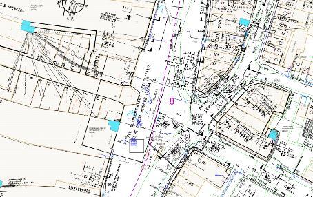
Figure 3-1 - Proposed Phase 1 Utility Diversion Route
Figure 3-2 - Plot S1, Plot S2 and Plot S3 Diversion Route (S1,S2, S4), excerpt from LSCWSP-ZZ-ZZ-DR-UT-000016

ELECTRICITY INFORMATION

GAS INFORMATION

POTABLE WATER INFORMATION
FOUL DRAINAGE INFORMATION
TELECOMMUNICATIONS INFORMATION

HSE INFORMATION
This Utility Statement has been produced on behalf of Landsec Lewisham Limited to assist with the delivery of the development proposed at Lewisham Shopping Centre. This report reviews the existing utility networks to understand:
▪ Extent of likely utility constraints.
▪ The ability of the existing electricity, gas, potable water, and telecommunications networks to support the anticipated utility loads.
WSP has obtained the utility record information for statutory undertakers known to be operating in the area of the site.
Record mapping was used to identify existing utilities which are routed within and in close proximity to the site, required diversionary works and to identify and request desirable points of connection in discussion with utility providers.
▪ WSP approached UK Power Networks on the 7th March 2024 to request a budget estimate for a supply of 1MVA, to determine whether local networks would have sufficient capacity to accommodate proposals, or whether network reinforcement will be required.
▪ UK Power Networks provided response (Ref 8500292677 dated 13th March 2024) outlining the budget estimate to supply the site with the 1,000kVA requested to accommodate the life safety systems.
▪ The budget estimate for scheme advised that the point of connection (POC) is to UK Power Networks high voltage network along Lewisham High Street and Rennell Street.
▪ It will be necessary to install an 1MVA package substation on site for the customer load of 1MVA. The following costs include for UKPN to trench from the point of connection to the customers substation position.
▪ WSP approached UK Power Networks on the 25th April 2024 to request a formal quotation for a supply of 16.5MVA, to determine whether local networks would have sufficient capacity to accommodate proposals, or whether network reinforcement will be required.
▪ UK Power Networks provided response (Ref 8600031297 dated 24th July 2024) outlining the costs to supply the site with the 16,500kVA requested.
▪ C3 budget diversionary quotations were requested from UK Power Networks to determine the extent of the works required to accommodate proposals.
▪ UK Power Networks issued (Ref 8500285147 dated 20th December 2023.)
▪ UK Power Networks advised that there are 2 network substations (Substations 81157 and 81158) located within the Phase 1 section which are network substations, and these will need to relocate as part of the Phase 1 works.
▪ C3 budget diversionary quotations were requested from UK Power Networks to determine the extent of the works required to accommodate S1, S2 and S3 proposals
▪ UK Power Networks issued (Ref 8500301114 dated 3rd June 2024.
▪ WSP is awaiting estimated diversion costs from UK Power Networks.
▪ No Gas supply is required for the new site development.
▪ C3 budget diversionary quotations were requested from SGN to determine the extent of the works required to accommodate proposals.
▪ SGN issued (Ref D2521912 dated 18th December 2023)
▪ SGN issued C3 estimated costs on the 13th March 2024 advising the outline budget estimated costs to divert their gas apparatus affected by the works.
▪ C3 budget diversionary quotations were requested from SGN to determine the extent of the works required to accommodate proposals
▪ SGN issued (Ref D2586392 dated 9TH August 2024).
▪ SGN issued C3 estimated costs on the 9th August 2024 advising the outline budget estimated costs to divert their gas apparatus affected by the works
▪ C3 budget diversionary quotations were requested from Thames Water to determine the extent of the works required to accommodate proposals
▪ Thames Water issued (Ref DS6119824 dated 30th May 2024.)
▪ WSP are awaiting estimated diversion costs from Thames Water.
▪ C3 budget diversionary quotations were requested from Thames Water to determine the extent of the works required to accommodate proposals
▪ Thames Water issued (Ref DS6119994 dated 3rd June 2024.)
▪ WSP are awaiting estimated diversion costs from Thames Water.
▪ C3 budget diversionary quotations were requested from Openreach to determine the extent of the works required to accommodate proposals.
▪ Openreach issued (Ref 907576 dated 22nd December 2023.)
▪ WSP are awaiting estimated diversion costs from Openreach.
▪ C3 budget diversionary quotations were requested from Openreach to determine the extent of the works required to accommodate proposals.
▪ Openreach issued (Ref 920302 dated 31st May 2024.)
▪ WSP are awaiting estimated diversion costs from Openreach.
▪ C3 budget diversionary quotations were requested from OCU Group to determine the extent of the works required to accommodate proposals.
▪ OCU group advised that they have cable installed in the Zayo duct route.
▪ Once Zayo has provided their response then this will need to be shared with OCU Group.
▪ C3 budget diversionary quotations were requested from Virgin Media to determine the extent of the works required to accommodate proposals.
▪ Virgin Media issued (Ref VM/CIP/460483 dated 13th March 2024).
▪ WSP are awaiting estimated diversion costs from Virgin Media
▪ C3 budget diversionary quotations were requested from Virgin Media to determine the extent of the works required to accommodate proposals
▪ Virgin Media issued (Ref VM/CIP/470681 dated 7th June 2024).
▪ WSP are awaiting estimated diversion costs from Virgin Media
▪ C3 budget diversionary quotations were requested from Vodafone to determine the extent of the works required to accommodate proposals
▪ Vodafone issued (Ref 10049 dated 18th December 2023).
▪ Vodafone issued C3 estimated costs on the 29th March 2024 advising the outline budget estimated costs to divert their gas apparatus affected by the works.
▪ C3 budget diversionary quotations were requested from Vodafone to determine the extent of the works required to accommodate proposals
▪ Vodafone issued (Ref 10043 dated 3rd June 2024).
▪ Vodafone issued C3 estimated costs on the 7th June 2024 advising the outline budget estimated costs to divert their gas apparatus affected by the works.
▪ C3 budget diversionary quotations were requested from Zayo to determine the extent of the works required to accommodate proposals.
▪ Zayo issued (Ref JSM/Zayo-23/797 dated 18th December 2023).
▪ Zayo advised that they have cable installed in the Virgin Media duct,
▪ Once Virgin Media has provided their response then this will need to be shared with Zayo.
The following telecommunication providers advised that they would not be affected by the proposal. EU networks, Neos, ESP
All foul water drainage from the proposed development will drop to the below ground drainage network. This network will be routed to the external courtyard and access road, and then outfall via a new 100mm diameter gravity connection to the 600mm diameter Thames Water foul sewer to the North of the site, via a demarcation manhole. This connection is subject to an S106 agreement with Thames Water. Non-return/flap valves are to be located in an accessible location within the network to protect against sewer surcharge.
A pre-development enquiry has been submitted as part of the wider Masterplan proposals, to confirm capacity within the public sewer network for the proposed foul flows.
There are no proposed alterations to the drainage network serving the existing retail units being retained in the north-east part of the site.
Foul water flows from plot N2 will be collected at a high level and be conveyed to the boundaries of the building, before connecting to the manholes located in the external pavement area via soil vent pipes. It will then connect to the wider WSP proposed masterplan foul network and discharge to the existing 600mm diameter Thames Water foul sewer located to the south of Rennell Street, via the proposed manhole.
Sitewide flood risk assessment and surface water drainage strategies is produced by Expedition. N2 surface water drainage strategy has been developed to align with it.
Roof area from the southwest corner of the plot will be picked up by rain water pipe and to be connected to Expedition masterplan podium surface water network.
Roof area from the rest of the plot will be picked up by rain water pipes and to be connected to Expedition masterplan underground surface water network which will discharge to the existing 229mm diameter Thames Water surface water sewer located to the south of Rennell Street, via proposed manhole.
Type C non-infiltration permeable paving is proposed for the external area, with fin drain proposed at the subbase to collect the runoff and connect to the N2 surface water network.
Sustainable drainage systems (SuDS) will be integrated with the masterplan surface water drainage network which will incorporate attenuation systems and rain gardens.
Attenuation volume for N2 will be provided within the attenuation tank located between plot N1 and N3. It has been sized to accommodate the 1 in 100-year storm event including an allowance of 40% for predicted climate change. As part of the sitewide drainage network, the runoff would be restricted to greenfield rates before discharging to the Thames Water sewer. Refer to Expedition masterplan drainage design for details.
A surface/foul water pre-developmentenquiryhasbeen made to TWto understand if there isadequate capacity to cater the Proposed Development. At the time of writing this report, WSP are still in the progress of liaising with Thames Water
This Utility Statement has been produced on behalf of Landsec Lewisham Limited to assist with the delivery of the development proposed Lewisham Shopping Centre.
The proposed development consists of a Hybrid planning application for the demolition and comprehensive, phased redevelopment of land at Lewisham Shopping Centre and adjacent land, comprising living uses, including residential, co-living and student accommodation, town centre uses as well as community and cultural uses.
The local authority is Lewisham Borough Council.

This report reviews the existing utility networks to understand:
▪ Extent of likely utility constraints
▪ The ability of the existing electricity, potable water, and telecommunications network to support the anticipated utility loads.
Utility network records have been used as the basis of ongoing consultation between WSP and utility stakeholders to identify proposed points of connection to accommodate the project proposals.
Records showing the distribution of private services within the site i.e. private networks, are unavailable to the design team.
WSP has undertaken an assessment of the load profile to predict the anticipated utility demands for the site.
Based on the anticipated loads, enquires have been issued to the incumbent electricity providers to assess the impact of the demands on their existing networks and/or reinforcement works to accommodate the proposals.
The required on-site infrastructure will be supplied from the existing networks surrounding the site and with the infrastructure and service connections distributed to and around the site below ground and arranged in accordance with Street Works UK (NJUG) guidelines. WSP has developed a utility strategy which indicates Points of Connection and an incoming services strategy
WSP has obtained utility record information for statutory undertakers known to be operating in the area of the site (Centara Desktop Utility Search Ref: CEN21191 Dated 8th September 2021).
Record mapping was used to identify existing utilities which are routed within and in close proximity to the site, to identify affected assets and potential diversions, and request desirable points of connection for new supplies in discussion with utility providers.
A list of the statutory undertakers is given in the table below and a list of responses is located in Appendix A. Table 1 – Incumbent Utility Network Providers
OCU Group, Neos, Virgin Media, Vodafone, Zayo
The following section outlines the existing utilities which are routed within and in close proximity to the site taken from record information obtained during this study.
From record mapping the following UK Power Network assets are noted.
▪ HV/LV networks are located around the Lewisham Shopping Centre development, some of this capacity may be able to be utilised for future supplies.


From record mapping the following SGN assets are noted.
▪ Low Pressure and Medium Pressure networks are located around the Lewisham Shopping Centre development.

From record mapping the following Thames Water assets are noted.
▪ Thames Water potable water assets are located in the roads surrounding the site, it is considered that local networks will act as points of connection for new phases.


From record mapping the following Openreach assets are noted.
▪ Openreach assets are located in the roads surrounding the site, it is considered that local networks will act as points of connection for new phases.


From record mapping the following EU Networks assets are noted.
▪ EU Networks assets are located in the roads surrounding the site, it is considered that local networks will act as points of connection for new phases.

From record mapping the following OCU Group assets are noted.
▪ OCU Group assets are located in the roads surrounding the site, it is considered that local networks will act as points of connection for new phases.

From record mapping the following Neos assets are noted.
▪ Neos assets are located in the roads surrounding the site, it is considered that local networks will act as points of connection for new phases.

From record mapping the following Virgin Media assets are noted.
▪ Virgin Media assets are located in the roads surrounding the site, it is considered that local networks will act as points of connection for new phases.

From record mapping the following Vodafone assets are noted.
▪ Vodafone assets are located in the roads surrounding the site, it is considered that local networks will act as points of connection for new phases.


From record mapping the following Zayo assets are noted.
▪ Zayo assets are located in the roads surrounding the site, it is considered that local networks will act as points of connection for new phases.

The electricity utility loadings calculated by WSP have been used as the basis of enquires with statutory utility companies, to determine the impact of these loadings on the existing utility infrastructure networks.
Table 2 – Utility Loading Summary
supply (life safety)
UK Power Networks is the Electricity Distribution Network Operator (DNO) for the site.
WSP has approached the incumbent utility provider to determine points of connection and any-off site reinforcement, or upgrade works required to supply the proposed development.
Table 3 – Electrical Load Assessment
confirmed as being from separate primary substation to main supply
We understand, of the 14 affected UKPN substations on the LSC development site, 7 of these are dedicated substations servicing LSC (substation numbers 81157, 81152, 80164 x 2, 81159, 81033 and 81148), with the remaining 7 substations being network substations servicing loads outside the development (81150, 81158, 81149, 81147, 81770, 81093 and 80387).
Of the three substations in Phase 1a, two are dedicated substations (81159 Riverdale Road R/O 66 and 81033 Molesworth Street Littlewoods) and one is a network substation, (81147 Lewisham High Street Woolworths)
WSP approached UK Power Networks on the 7TH March 2024 to request a budget estimate for a supply of 1MVA, to determine whether local diverse networks would have sufficient capacity to accommodate a 1MVA supply for the life safety systems.
UK Power Networks provided response (Ref 8500292677 dated 13th March 2024) outlining the budget estimate to supply the site with the 1,000kVA requested.
It will be necessary to install an 1MVA package substation on site for the customer load of 1MVA. The costs include for UKPN to trench from the point of connection to the customers substation position.
UKPN was unable to provide details in a budget quotation of a truly diverse supply coming from a separate primary substation to the main supply, and that a formal quotation would need to be sought to determine this feasibility.
WSP approached UK Power Networks on the 25th April 2024 to request a formal quotation for a supply of 16.5MVA, to determine whether local networks would have sufficient capacity to accommodate proposals, or whether network reinforcement will be required.
UK Power Networks provided response (Ref 8600031297 dated 24th July 2024) outlining the formal quotation to supply the site with the 16,500kVA requested. The proposal is to provide 4No. 11kV cables from Deptford Grid Substation, feeding 4No. Ring Main Units on the site. The following is from the UKPN quotation Contestable works section.
Fit actuator to circuit breaker.
Sand & cap/shingle substation
300mm HV indoor end box termination
Installation of secondary substation lighting and power in brick substation.
Establish an 11kV switchroom within a brick-built chamber. Includes Ring Main Unit with relay, Air Metering Unit, RTU, and switchroom ancillaries. Excludes earthing, civil works, and HV jointing.
Transport of plant to site in normal weekday working hours
Installation of a transformer-mounted 11kV Ring Main Unit with relay.
Installation of a Remote Terminal Unit (RTU).
Install earthing in brick secondary substation
High voltage injection test
Connect and install COP3 HV metering termination cubicle and multicore termination.
Commissioning of a Remote Terminal Unit (RTU)
Supply only of 11kV 300mm aluminium Triplex mains cable
Supply only of 11kV 300mm copper Triplex mains cable
Contractor Civil works
125mm Ridgiduct Solid (supplied in multiples of 6m lengths)
300mm inline jointing kits
Tile tape (up to 22kV) per 40m roll
11kV 300mm to 300mm Triplex straight joint (final closing joint)
The incoming potable mains cold water supplies will be fed from the roads surrounding the development. There are potable water mains in both Lewisham High Street to the east and in Molesworth Street to the west.
Telecommunications requirements for the emerging masterplan have been discussed between WSP and Landsec ICT teams. The site is surrounded by multiple telecommunications providers’ apparatus, providing significant options for new fibre infrastructure.
Telecommunications operators will typically include, but not be limited to:
BT Openreach
Hyperoptic
Virgin Media
Colt
Vodafone
Providers will be aggregates into single ‘meet-me’ chambers located on the development phase boundary with connections made into local utility networks or adjacent phases as is most appropriate given the phase layout and access to adjacent utility networks.
All foul water drainage from the proposed development will drop to the below ground drainage network at drop points specified by WSP MEP team. This network will be routed to the external courtyard and access road, and then outfall via a new 100mm diameter gravity connection to the 600mm diameter Thames Water foul sewer to the North of the site, via a demarcation manhole. This connection is subject to an S106 agreement with Thames Water. Non-return/flap valves are to be located in an accessible location within the network to protect against sewer surcharge.
A pre-development enquiry has been submitted as part of the wider Masterplan proposals, to confirm capacity within the public sewer network for the proposed foul flows.
There are no proposed alterations to the drainage network serving the existing retail units being retained in the north-east part of the site.
Figure 2-1 – Excerpt from Elliott Wood drawing 2230538-EWP-ZZ-XX-DR-C-10001: N1 Below Ground Drainage Proposed Layout

Foul water flows from plot N2 will be collected at a high level and be conveyed to the boundaries of the building, before connecting to the manholes located in the external pavement area via soil vent pipes. It will then connect to the wider WSP proposed masterplan foul network and discharge to the existing 600mm diameter Thames Water (TW) foul sewer located to the south of Rennell Street, via the proposed manhole.
Sitewide flood risk assessment and surface water drainage strategies is produced by Expedition. N2 surface water drainage strategy has been developed to align with it.
Roof area from the southwest corner of the plot will be picked up by rain water pipe and to be connected to Expedition masterplan podium surface water network.
Roof area from the rest of the plot will be picked up by rain water pipes and to be connected to Expedition masterplan underground surface water network which will discharge to the existing 229mm diameter TW surface water sewer located to the south of Rennell Street, via proposed manhole.
Type C non-infiltration permeable paving is proposed for the external aera, with fin drain proposed at the subbase to collect the runoff and connect to the N2 surface water network.
Sustainable drainage systems (SuDS) will be integrated with the masterplan surface water drainage network which will incorporate attenuation systems and rain gardens.
Attenuation volume for N2 will be provided within the attenuation tank located between plot N1 and N3. It has been sized to accommodate the 1 in 100-year storm event including an allowance of 40% for predicted climate change. As part of the sitewide drainage network, the runoff would be restricted to greenfield rates before discharging to the TW sewer. Refer to Expedition masterplan drainage design for details.
A surface/foul water pre-developmentenquiryhasbeen made to TWto understand if there isadequate capacity to cater the Proposed Development. At the time of writing this report, WSP are still in the progress of liaising with TW
SuDS provide natural variability in their ability to remove contamination from surface water runoff which drains across a site, therefore the management of water quality is founded on a risk-based approach. The current SuDS Manual (C753) suggests a risk-based approach based on land use type and specific contaminants.
The SuDS Manual (C753), Table 26.1 suggests a Simple Index Approach (SIA) for low risk developments, which follows a three-step process, namely:
Allocate suitable pollution hazard indices for the proposed land use.
Select SuDS with a total pollution mitigation index that equals or exceeds the pollution hazard index.
Where the discharge is protected surface waters or groundwater, consider the need for a more precautionary approach.
To successfully deliver adequate treatment, the chosen SuDS components should have a total pollution mitigation index that equals or exceeds the pollution hazard index.
Total SuDS mitigation index ≥ Pollution hazard index
Where the mitigation index of an individual component is insufficient, two components (or more) in series will be required, where:
Total SuDS mitigation index = mitigation index1 + 0.5 (mitigation index2)
Where:
Mitigation Index n = mitigation index for component n
A factor of 0.5 is used to account for the reduced performance of secondary or tertiary components associated with already reduced inflow concentration.
Pollution Hazard values table below has been produced and builds on information provided within the SuDS Manual.
Figure 2-2 - Pollution Hazard Values
Other Roofs (typically commercial/industrial roofs)
(up to 0.8 where there is potential for metals to leach from roof)
Individual Property driveways, residential car parks. Low traffic roads (e.g. cul-de-sacs, homezones and general access roads) and nonresidential car parks with infrequent change (e.g. schools, offices) – i.e. <300 traffic movements/day.
Commercial Yard and delivery areas, nonresidential parking with frequent change (e.g. hospitals/retail); all roads except low traffic roads and trunk roads/ motorways1
Sites with heavy pollution (e.g. haulage yards, lorry parks, highly frequented lorry approaches to industrial

estates, waste sites); sites where chemicals and fuels (other than domestic fuel oil) are to be delivered, handled, stored, used or manufactured; industrial site; trunk roads and motorways.1
1 Motorways and trunk roads should follow the guidance and risk assessment process set out in Highways Agency (2009).
2 These should only be used if considered appropriate as part of a detailed risk assessment –required for all these land use types (see also SuDS manual Table 4.3). When dealing with high hazard sites, the environmental regulator should first be consulted for pre-permitting advice. This will help to determine the most appropriate treatment approach to the development of a design solution
The development proposal for N2 comprises of residential roof area
Pollution hazard indices shown in the table below have been considered.
Commercial Yard and delivery areas, nonresidential parking with frequent change (e.g. hospitals/retail); all roads except low traffic roadsandtrunk roads/motorways1
Different SuDS Mitigation Indices for each type of SuDS component are identified in figure below (reproduced from Table 26.3 in C753).
Figure 2-4 - SuDS Mitigation Indices for each type of SuDS component
From the tables above, the SuDS mitigation index within the Site is greater than the pollution hazard index, therefore meeting the requirements of the SIA as specified in CIRIA C753. This will be further reviewed during the detailed design with Expedition.
The below drainage requirements table has been produced and builds on information provided within the SuDS Manual; it is expected a suitably qualified maintenance specialist will undertake the work for the entire development.
Figure 2-5 – Drainage requirements
Drainage Feature Regular Maintenance Occasional Maintenance Monitoring
Manholes / Inspection Chambers
Check for accumulation of debris and silt and cleaned as necessary.
Covers and frames to be checked for damage.
Exposed concrete and adjacent surfacing to be checked for cracking and general damage.
Check condition of inlet and outlet pipes, flow controls, baffles and isolation structures
Clean as necessary.
All manhole and inspection chamber covers and frames to be replaced as necessary.
Repair exposed concrete and surfacing necessary
Repair/rehabilitation of inlets, outlet, overflows and vents, as required.
Inspect every 6 months or after large storm.
The design of the proposed surface and foul water drainage infrastructure should be developed through future design stages, as and where appropriate, in accordance with the standards and criteria outlined below.
Design Standards
BS EN 752:2017 Drainage and gravity systems outside buildings
BS EN 12056:200 Gravity drainage systems inside buildings
BS EN 16933-2:2017 Drain and sewer systems outside buildings, Design, Part 2: Hydraulic Design
General References
CIRIA Report C73 – The SUDS Manual
Water UK – Sewerage Sector Guidance
The Building Regulations Approved Document H: Drainage and Waste Disposal
Greater London Authority – The London Plan
Assessment Criteria
The proposed surface water drainage network should be designed to the following criteria to comply with British and European Standards BS EN 752:2017 and BS EN 16933-2:2017;
No significant surcharging (gravity flow only) for storm flows with a 50% AEP
No flooding for storm flows with a 3% AEP
No flooding off-site or flooding that would present a risk to person or property for storms with a 1% AEP
In line with local and regional standards, a 40% allowance for climate change will be applied to all calculations for network design.
This section of the report identifies the anticipated affected utilities which will require diversion. A number of services exist within the development and will require diversion / disconnection, including electrical substations, both dedicated to LSC and UKPN Network substations servicing other customers, BT Openreach networks, gas and water connections to units and drainage assets
Services are also located in the highways and footways surrounding the site. Lewisham High Street to the east, Rennell Street to the north, Molesworth Street to the west and south.
Utility record information indicates the presence of utilities in footways in these locations and will require diverting into the highway where the proposed building line is being extended out onto these footways. WSP has engaged with the utility authorities regarding diversionary works, and proposals to route the services in a joint utility trench.
PHASE 1 DIVERSIONS

A number of utilities which currently run in the southern footway of Rennell Street are affected by the proposed alterations to the north, and a coordinated utilities corridor is proposed as part of the enabling works package to clear the development site ahead of pre-construction activities. We would allow a minimum timeframe of 18months to implement this diversion, which means that whilst
the RIBA stage 3 works are progressing for Phase 1, the diversions to the north can be undertaken. This will require the submission of C4 (detailed diversion) applications, and the provisioning of detailed information regarding finish levels and a procurement strategy as to how the works will be procured.
The diversions will be most effectively and easily managed through a single works package, an appointed Principal Contractor undertaking the civils work elements (trenching, backfilling and reinstatement), with the utility companies undertaking the design and installation of their services, with WSP acting as the utilities consultant coordinating the designs and preparing the coordinated utilities trench details for the Design & Build contractor to develop for construction.
The Rennell Street utilities corridor is proposed to divert services into Rennel Street Highway and Molesworth Street. At Stage 3, A Ground Penetrating Radar Survey will be required to determine the extent of services in Rennell Street and Molesworth Street and to prove that the proposed utility diversion route is viable.
A further utility diversion corridor is anticipated to the south west of the development, where buildings C3, S1, S2 and S4 extend out onto the eastern footway of Molesworth Street. While not in Phase 1, and therefore not on the critical programme path, WSP has sought utility diversionary quotations from affected statutory undertakers, information of which is provided in the utility tracker. See drawing: LSC-WSP-ZZ-ZZ-DR-UT-000016
Figure 3-2 - Molesworth Street Diversion Route (S1,S2, S4), excerpt from LSC-WSP-ZZ-ZZ-DRUT-000016

Elsewhere diversions and disconnections will be managed on a plot by plot basis.
BT and UKPN have apparatus on the LSC development which will require overlaying with the proposed demolition plan to determine when diversions will be required. This detail will be shared as the construction logistics plans are developed.
C3 budget diversionary quotations were requested from UK Power Networks to determine the extent of the works required to accommodate proposals.
UK Power Networks issued (Ref 8500285147 dated 20th December 2023.)
UK Power Networks advised that there are 2 network substations (Substations 81157 and 81158) located within the Phase 1 section which are network substations, and these will need to be relocated as part of the Phase 1 works.
C3 budget diversionary quotations were requested from UK Power Networks to determine the extent of the works required to accommodate proposals
UK Power Networks issued (Ref 8500301114 dated 3RD June 2024.
WSP are awaiting estimated diversion costs from UK Power Networks.
C3 budget diversionary quotations were requested from SGN to determine the extent of the works required to accommodate proposals
SGN issued (Ref D2521912 dated 18th December 2023)
SGN issued C3 estimated costs on the 13th March 2024 advising the outline budget estimated costs to divert their gas apparatus affected by the works to accommodate the proposals.
C3 budget diversionary quotations were requested from SGN to determine the extent of the works required to accommodate proposals
SGN issued (Ref D2586392 dated 9TH August 2024).
SGN issued C3 estimated costs on the 9th August 2024 advising the outline budget estimated costs to divert their gas apparatus to accommodate the development.
PHASE
C3 budget diversionary quotations were requested from Thames Water to determine the extent of the works required to accommodate proposals
Thames Water issued (Ref DS6119824 dated 30th May 2024.)
WSP are awaiting estimated diversion costs from Thames Water.
C3 budget diversionary quotations were requested from Thames Water to determine the extent of the works required to accommodate proposals
Thames Water issued (Ref DS6119994 dated 3rd June 2024.)
WSP are awaiting estimated diversion costs from Thames Water.
PHASE 1
C3 budget diversionary quotations were requested from Openreach to determine the extent of the works required to accommodate proposals
Openreach issued (Ref 907576 dated 22nd December 2023.)
WSP are awaiting estimated diversion costs from Openreach.
C3 budget diversionary quotations were requested from Openreach to determine the extent of the works required to accommodate proposals
Openreach issued (Ref 920302 dated 31st May 2024.)
WSP are awaiting estimated diversion costs from Openreach.
PHASE 1
C3 budget diversionary quotations were requested from OCU Group to determine the extent of the works required to accommodate proposals
OCU group advised that they have cable installed in the Zayo duct route.
Once Zayo has provided their response then this will need to be shared with OCU Group.
PHASE 1
C3 budget diversionary quotations were requested from Virgin Media to determine the extent of the works required to accommodate proposals
Virgin Media issued (Ref VM/CIP/460483 dated 13th March 2024).
WSP are awaiting estimated diversion costs from Virgin Media
C3 budget diversionary quotations were requested from Virgin Media to determine the extent of the works required to accommodate proposals.
Virgin Media issued (Ref VM/CIP/470681 dated 7th June 2024).
WSP are awaiting estimated diversion costs from Virgin Media
PHASE 1
C3 budget diversionary quotations were requested from Vodafone to determine the extent of the works required to accommodate proposals.
Vodafone issued (Ref 10049 dated 18th December 2023).
Vodafone issued C3 estimated costs on the 29th March 2024 advising the outline budget estimated costs to divert their gas apparatus to accommodate the development.
C3 budget diversionary quotations were requested from Vodafone to determine the extent of the works required to accommodate proposals
Vodafone issued (Ref 10043 dated 3rd June 2024).
Vodafone issued C3 estimated costs on the 7th June 2024 advising the outline budget estimated costs to divert their gas apparatus to accommodate the development.
PHASE 1
C3 budget diversionary quotations were requested from Zayo to determine the extent of the works required to accommodate proposals
Zayo issued (Ref JSM/Zayo-23/797 dated 18th December 2023).
Zayo advised that they have cable installed in the Virgin Media duct (PIA)
Once Virgin Media has provided their response then this will need to be shared with Zayo.
The following telecommunication providers advised that they would not be affected by the proposal. EU networks, Neos, ESP
In Summary, existing infrastructure networks have been identified in close proximity to the Lewisham Shopping Centre development.
During this round of consultation, the following has been established.
▪ The utility load assessment is to be reviewed as the scheme develops as changes may affect the estimated loads and findings outlined to date.
▪ Formal construction applications are to be pursued in line with the construction programme.
▪ For utility assets installed in non-adopted/3rd party land it will be necessary to ensure the required legal agreements are in place prior to the on-site works being undertaken.
▪ It will be necessary to undertake intrusive/non-intrusive surveys in key areas to validate record information obtained from the affected utility stakeholders at an appropriate time during the development of the masterplan.
▪ Based on the information obtained to date, it is not anticipated that there will be any utilities or sewerage constraints on the proposed development.
▪ WSP approached UK Power Networks on the 7th March 2024 to request a budget estimate for a supply of 1MVA, to determine whether local networks would have sufficient capacity to accommodate proposals, or whether network reinforcement will be required.
▪ UK Power Networks provided response (Ref 8500292677 dated 13th March 2024) outlining the budget estimate to supply the site with the 1,000kVA requested to accommodate the life safety systems.
▪ It will be necessary to install an 1MVA package substation on site for the customer load of 1MVA. The costs include for UKPN to trench from the point of connection to the customers substation position.
▪ WSP approached UK Power Networks on the 25th April 2024 to request a formal quotation for a supply of 16.5MVA, to determine whether local networks would have sufficient capacity to accommodate proposals, or whether network reinforcement will be required.
▪ UK Power Networks provided response (Ref 8600031297 dated 24th July 2024) outlining the formal quotation to supply the site with the 16,500kVA requested.
▪ All UK Power Networks work is to be carried out as a continuous programme of work that can be completed substantially within 12 months from the acceptance of the formal offer.
▪ C3 budget diversionary quotations were requested from UK Power Networks to determine the extent of the works required to accommodate proposals
▪ UK Power Networks issued (Ref 8500285147 dated 20th December 2023.)
▪ UK Power Networks advised that there are 2 network substations (Substations 81157 and 81158) located within the Phase 1 section which are network substations, and these will need to be relocated as part of the Phase 1 works.
▪ C3 budget diversionary quotations were requested from UK Power Networks to determine the extent of the works required to accommodate proposals
▪ UK Power Networks issued (Ref 8500301114 dated 3RD June 2024.
▪ WSP are awaiting estimated diversion costs from UK Power Networks.
▪ If the developer would like to proceed to a C4, then a new application will need to be submitted to UK Power Networks.
▪ No Gas supply is required for the new site development.
▪ C3 budget diversionary quotations were requested from SGN to determine the extent of the works required to accommodate proposals.
▪ SGN issued (Ref D2521912 dated 18th December 2023)
▪ SGN issued C3 estimated costs on the 13th March 2024 advising the outline budget estimated costs to divert their gas apparatus to accommodate the development.
▪ C3 budget diversionary quotations were requested from SGN to determine the extent of the works required to accommodate proposals
▪ SGN issued (Ref D2586392 dated 9TH August 2024).
▪ SGN issued C3 estimated costs on the 9th August 2024 advising the outline budget estimated costs to divert their gas apparatus affected by the works.
▪ Once formal C4 application is submitted to SGN, the estimated cost could decrease or increase but at this stage this figure is for guidance only.
▪ The incoming potable mains cold water supplies will be fed from the roads surrounding the development. There are potable water mains in both Lewisham High Street to the east and in Molesworth Street to the west.
▪ C3 budget diversionary quotations were requested from Thames Water to determine the extent of the works required to accommodate proposals
▪ Thames Water issued (Ref DS6119824 dated 30th May 2024.)
▪ WSP are awaiting estimated diversion costs from Thames Water.
▪ C3 budget diversionary quotations were requested from Thames Water to determine the extent of the works required to accommodate proposals.
▪ Thames Water issued (Ref DS6119994 dated 3rd June 2024.)
▪ WSP are awaiting estimated diversion costs from Thames Water.
▪ All foul water drainage from the proposed development will drop to the below ground drainage network. This network will be routed to the external courtyard and access road, and then outfall via a new 100mm diameter gravity connection to the 600mm diameter Thames Water foul sewer to the North of the site, via a demarcation manhole. This connection is subject to an S106 agreement with Thames Water. Non-return/flap valves are to be located in an accessible location within the network to protect against sewer surcharge.
▪ A pre-development enquiry has been submitted as part of the wider Masterplan proposals, to confirm capacity within the public sewer network for the proposed foul flows.
▪ There are no proposed alterations to the drainage network serving the existing retail units being retained in the north-east part of the site.
▪ Foul water flows from plot N2 will be collected at a high level and be conveyed to the boundaries of the building, before connecting to the manholes located in the external pavement area via soil vent pipes. It will then connect to the wider WSP proposed masterplan foul network and discharge to the existing 600mm diameter TW foul sewer located to the south of Rennell Street, via proposed manhole.
▪ Sitewide flood risk assessment and surface water drainage strategies is produced by Expedition. N2 surface water drainage strategy has been developed to align with it.
▪ Roof area from the southwest corner of the plot will be picked up by rain water pipe and to be connected to Expedition masterplan podium surface water network.
▪ Roof area from the rest of the plot will be picked up by rain water pipes and to be connected to Expedition masterplan underground surface water network which will discharge to the existing 229mm diameter TW surface water sewer located to the south of Rennell Street, via proposed manhole.
▪ Type C non-infiltration permeable paving is proposed for the external aera, with fin drain proposed at the subbase to collect the runoff and connect to the N2 surface water network.
▪ Sustainable drainage systems (SuDS) will be integrated with the masterplan surface water drainage network which will incorporate attenuation systems and rain gardens.
▪ Attenuation volume for N2 will be provided within the attenuation tank located between plot N1 and N3. It has been sized to accommodate the 1 in 100-year storm event including an allowance of 40% for predicted climate change. As part of the sitewide drainage network, the runoff would be restricted to greenfield rates before discharging to the TW sewer. Refer to Expedition masterplan drainage design for details.
▪ A surface/foul water pre-development enquiry has been made to TW to understand if there is adequate capacity to cater the Proposed Development. At the time of writing this report, WSP are still in the progress of liaising with TW.
▪ SuDS provide natural variability in their ability to remove contamination from surface water runoff which drains across a site, therefore the management of water quality is founded on a risk-based approach. The current SuDS Manual (C753) suggests a risk-based approach based on land use type and specific contaminants.
▪ The SuDS Manual (C753), Table 26.1 suggests a Simple Index Approach (SIA) for low risk developments, which follows a three-step process, namely:
▪ Allocate suitable pollution hazard indices for the proposed land use.
▪ Select SuDS with a total pollution mitigation index that equals or exceeds the pollution hazard index.
▪ Where the discharge is protected surface waters or groundwater, consider the need for a more precautionary approach.
▪ To successfully deliver adequate treatment, the chosen SuDS components should have a total pollution mitigation index that equals or exceeds the pollution hazard index.
▪ C3 budget diversionary quotations were requested from Openreach to determine the extent of the works required to accommodate proposals.
▪ Openreach issued (Ref 907576 dated 22nd December 2023.)
▪ WSP are awaiting estimated diversion costs from Openreach.
▪ C3 budget diversionary quotations were requested from Openreach to determine the extent of the works required to accommodate proposals
▪ Openreach issued (Ref 920302 dated 31st May 2024.)
▪ WSP are awaiting estimated diversion costs from Openreach.
▪ C3 budget diversionary quotations were requested from OCU Group to determine the extent of the works required to accommodate proposals
▪ OCU group advised that they have cable installed in the Zayo duct route.
▪ Once Zayo has provided their response then this will need to be shared with OCU Group.
▪ C3 budget diversionary quotations were requested from Virgin Media to determine the extent of the works required to accommodate proposals
▪ Virgin Media issued (Ref VM/CIP/460483 dated 13th March 2024).
▪ WSP are awaiting estimated diversion costs from Virgin Media
▪ C3 budget diversionary quotations were requested from Virgin Media to determine the extent of the works required to accommodate proposals
▪ Virgin Media issued (Ref VM/CIP/470681 dated 7th June 2024).
▪ WSP are awaiting estimated diversion costs from Virgin Media
▪ C3 budget diversionary quotations were requested from Vodafone to determine the extent of the works required to accommodate proposals
▪ Vodafone issued (Ref 10049 dated 18th December 2023).
▪ Vodafone issued C3 estimated costs on the 29th March 2024 advising the outline budget estimated costs to divert their gas apparatus affected by the works
▪ C3 budget diversionary quotations were requested from Vodafone to determine the extent of the works required to accommodate proposals
▪ Vodafone issued (Ref 10043 dated 3rd June 2024).
▪ Vodafone issued C3 estimated costs on the 7th June 2024 advising the outline budget estimated costs to divert their gas apparatus affected by the works
▪ C3 budget diversionary quotations were requested from Zayo to determine the extent of the works required to accommodate proposals
▪ Zayo issued (Ref JSM/Zayo-23/797 dated 18th December 2023).
▪ Zayo advised that they have cable installed in the Virgin Media duct,
▪ Once Virgin Media has provided their response then this will need to be shared with Zayo.


Mr. Andrew Smith
WSP UK LTD
The Mailbox
100, Wharfside Street BIRMINGHAM
B1 1RT
Dear Mr. Smith
Office Company:
Registered in England and Wales No: 3870728
Date: 13 March 2024
Our Ref: 8500292677 / QID 3000049311
Site Address: OFF MOLESWORTH STREET / LEWISHAM SE13 7HB
Budget estimate
I am writing to you on behalf of London Power Networks plc the licensed distributor of electricity for the above address trading as and referred to in this Quote as “UK Power Networks”. Thank you for your recent enquiry regarding the above premises
I am pleased to be able to provide you with a budget estimate for the Works.
It is important to note that this budget estimate is intended as a guide only. It may have been prepared without carrying out a site visit or system studies. No enquiry has been made as to the availability of consents or the existence of any ground conditions that may affect the ground works and only a cursory assessment of any Reinforcement costs that may be applicable has been undertaken. A detailed evaluation of any potential Reinforcement costs, including the applicability of the High-Cost Project Threshold and associated Cost Apportionment Factor will be undertaken upon receipt of a formal application for a Connection Offer. This Budget Estimate is not an offer to provide the connection and nor does it reserve any capacity on UK Power Networks’ electricity distribution system.
Description of work included:
The budget estimation for the Works is:
This report constitutes a desktop study, devoid of physical inspections to ascertain the point of connection (PoC). Therefore, it is imperative to acknowledge that the pricing and PoC may undergo alterations during the formal stage.
It will be necessary to install an 1MVA package substation on site for the customer load of 1MVA. The following costs include for UKPN to trench from the point of connection (POC) to the customers substation position. We will accept customer offered single copper cables and terminate to 2 x 800amp way fused at 800amps from adjacent intake room or an 1600amp ACB To establish a backup power supply, UK Power Networks (UKPN) will undertake trenching operations spanning approximately 155 meters to facilitate the installation of another Ring Main Unit. This point of connection (PoC) will be fed from a different feeder, originating from the same primary source.
High Voltage Point Of Connection
£400,000 00 (exclusive of VAT) if the Point Of Connection (POC) is to our High Voltage network along Lewisham High Street and Rennel Street
Assumptions
This budget estimate is based on the following assumptions:
• The most appropriate Point of Connection (POC) is as described above.
• A viable cable or overhead line route exists along the route we have assumed between the Point of Connection (POC) and your site
• In cases where the Point of Connection (POC) is to be at High Voltage, that a substation can be located on your premises at or close to the position we have assumed
• Where electric lines are to be installed in private land UK Power Networks will require an easement in perpetuity for its electric lines and in the case of electrical plant the freehold interest in the substation site, on UK Power Networks terms, without charge and before any work commences
• You will carry out, at no charge to UK Power Networks, all the civil works within the site boundary, including substation bases, substation buildings where applicable and the excavation/reinstatement of cable trenches
• Unless stated in your application, all loads are assumed to be of a resistive nature. Should you intend to install equipment that may cause disturbances on UK Power Networks' electricity distribution system (e.g. motors; welders; etc.) this may affect the estimate considerably
• All UK Power Networks' work is to be carried out as a continuous programme of work that can be completed substantially within 12 months from the acceptance of the Quote
Please note that if any of the assumptions prove to be incorrect, this may have a significant impact on the price in any subsequent Quote. You should note also that UK Power Networks' formal Quote may vary considerably from the budget estimate. If you place reliance upon the budget estimate for budgeting or other planning purposes, you do so at your own risk.
If you would like to proceed to a formal offer of connection then you must apply for a Quote Please refer to our website click here to complete application process.
To help us progress any future enquiry as quickly as possible please quote the UK Power Networks Reference Number from this letter on all correspondence.
If you have any questions about your budget estimate or need more information, please do not hesitate to contact me. The best time to call is between the hours of 9am and 4pm, Monday to Friday. If the person you need to speak to is unavailable or engaged on another call when you ring, you may like to leave a message or call back later.
Yours sincerely
Naveed Din
Mobile: 07592 330 268
Email: Naveed.din@ukpowernetworks.co.uk

To download your free safety leaflets and resources visit UK Power Networks - Safety Page

Mr. Andrew Smith
WSP UK Ltd The Mailbox 100, Wharfside Street BIRMINGHAM
B1 1RT
Dear Mr. Smith
Registered Office Company:
Registered in England and Wales No: 3870728
Date: 24 July 2024
Our Ref: 8600031297 / QID 3600011656
Customer Ref: n/a
Site Address: Lewisham Shopping Centre, Molesworth Street, London SE13 7HB
I am writing to you on behalf of London Power Networks plc the licensed distributor of electricity for the above address trading as and referred to in the Quote as “UK Power Networks”. Thank you for your recent enquiry regarding the above site. I am pleased to be able to provide you with this Quote to carry out the work requested.
The Works will enable the provision of an import capacity of 16,500 kVA, and a maximum export capacity of 0KW.
UK Power Networks would like to carry out all of the requested work for you. However, other companies can do some or all of the work for you; these are known as Independent Connection Providers (ICPs). You can approach NERS accredited ICPs directly, or you can approach an Independent Distribution Network Operator (IDNO) to request this work and they will arrange for an ICP to carry out the Contestable Works. To find out more about which ICPs work in our area and what work they can undertake please click here
To give you as much choice as possible we are able to offer you the following options for getting your work done:


UK Power Networks carries out all of the requested ‘contestable’ and ‘non-contestable’ works required for your connection
UK Power Networks carries out all the ‘non-contestable’ work and the ‘contestable closing joint’. The ICP carries out all other requested ‘contestable’ work
UK Power Networks carries out the ‘non-contestable’ works only. The ICP carries out all of the works classified as ‘contestable’
£4,360,215.95
£260,140.51
£256,628.35
£5,232,259.13
£312,168.61
£307,954.02
A short guide is available to help you understand the three different Prices (options A, B and C). To see this guide please click here
Provisional Price
I would like to draw to your attention to the provisional nature of the Quote. At the date of issue, the detailed design and/or the procurement process is not complete and the proposed design is dependent on securing Consents and Land Rights that have not yet been obtained from third parties. We will notify you in writing if the Works, the completion date or the Price need to be adjusted once the detailed design and the procurement process is complete
and the Consents and Land Rights have been obtained.
Terms and Conditions
The Quote is subject to version 7 (September 2016) of our Terms and Conditions For Connection and Diversionary Works (the “Terms and Conditions”) which you can view here. Alternatively, please let me know if you would like me to send you a copy in the post The Terms and Conditions create legally binding obligations and, amongst other things, contain caps and exclusions on UK Power Networks’ liability to you and grounds for variation and termination. Therefore, it is important that you take the time to read and understand them. They also contain definitions of terms used in this document and in the linked pages on our website, which you may find helpful such as “DNO” and “DNO Works”.
If your development requires an Environmental Impact Assessment before planning permission will be granted you must write to UK Power Networks confirming that this is the case and provide reasonable supporting documentation. UK Power Networks may then issue a revised Milestone Table which will reflect that it may take longer to get the necessary planning permission for your development.
If factors outside of your control impact upon the achievement of your milestones you must write to UK Power Networks as soon as practical and provide reasonable supporting documentation. UK Power Networks may (but is not obliged to) issue a revised Milestone Table.
If you fail to either (i) discharge any of the milestones or (ii) provide to UK Power Networks reasonable evidence of their discharge within the relevant period in accordance with the Milestone Table (or any such later revision of the Milestone Table that UK Power Networks may issue), UK Power Networks may write to you giving you 30 days to provide suitable evidence to UK Power Networks that you have discharged the relevant milestone. If you fail to provide such evidence within 30 days (or such longer period as UK Power Networks may agree in writing) you shall be deemed to have committed a material breach of the Quote and UK Power Networks may terminate the Quote by giving you written notice.
If UK Power Networks terminates the Quote due to your failure to achieve a milestone or provide evidence that it has been achieved within the relevant period you will be required to pay UK Power Networks such sums as would be payable to UK Power Networks under clauses 15.3, 15.4 and 15.8 of the Terms and Conditions as if the DNO had terminated the Quote in accordance with clause 15.1.1.
To reflect the above connections queue management regime clause 3.3.3(ii) of the terms and conditions is deemed to be deleted and replaced with “not used”
Special Conditions
The Quote is based on a high–level desktop study. Therefore, both the Quote and the connection are subject to, and conditional upon, the following special conditions:-
Special Conditions applicable to the Quote
General – Planning Permission
You are under an obligation to provide the required Planning Permissions (if applicable) for Your Works, associated plans, reports and documents with the Planning Permission (for example landscaping plans) and to keep the DNO informed of any changes to the same throughout the Works.
General - Consents
The Quote is based on the use of an approved solicitor from UK Power Networks’ panel to obtain and complete the associated legal consents and Land Rights for UK Power Networks. If an approved solicitor from UK Power Networks’ panel is not used, UK Power Networks shall be entitled to vary either or both of the Price and the date for completion to reflect any additional Costs and/or delays associated with not using a panel solicitor.
Cable Route – Cable route from the Point of Connection to your site
The Quote is based on a high level desktop study of the proposed cable route but has not considered any specific requirements that may make the installation of the cable route more difficult or expensive such as (but not limited to):
- engineering difficulties
- the presence of Adverse Ground Conditions
Special Conditions applicable to the Quote
- the presence of concrete
- the presence of underground structures or any gas, electric mains, or oil pipelines in the vicinity of the Site
- the presence of culverts
- the presence of archeologically or environmentally sensitive areas (e.g. SSSI)
- measures to mitigate the impact of the DNO Works on the environment and ecosystem
- the presence of tree roots or the need for tree and vegetation clearance
- the need to cross watercourses or railways
- route restrictions
- traffic management requirements
- the presence of or the need to repair any existing land drains encountered
- the availability of the necessary Land Rights and Consents on terms acceptable to UK Power Networks
- the requirement for any non-standard road or footway finishes/reinstatements or any lines or markings
- the requirement for an excavation to be re-instated with a material other than that which was excavated
- any requirements that may be requested by the relevant local authorities
If the detailed design or route-proving indicates that there are impediments with using the proposed cable route which make the proposed route unsuitable or the installation of the cable route more difficult or expensive, or which change the manner in which UK Power Networks will need to carry out the DNO Works, UK Power Networks will notify you in writing if the Works, date for completion or the Price need to be adjusted and shall be entitled to vary the Works, the date for completion and the Price accordingly.
Cable Route - Local Authority charges
The Quote does not include for any Costs that may be incurred in obtaining Consents from the local authority or road authority or for charges payable to the local authority or road authority that may be incurred in the carrying out of the Works, including (but not limited to) traffic management charges, lane rental charges, parking bay suspensions, red route closures and street charges. UK Power Networks will notify you in writing if it determines that the Works, date for completion or the Price need to be adjusted to reflect delays in obtaining or complying with Consents from the local authority or road authority and any associated charges and UK Power Networks shall be entitled to vary the Works, the date for completion and the Price accordingly.
Cable Route - 11kV Cable Rating – Connection at the Primary substation
Please note that if you undertake the Contestable Works you must use 300mm2 copper cable for the first 250m of 11kV cable connected to the proposed feeder circuit breaker at the Deptford Primary Substation
Customer Substation - DNO substation on Customer site
You must complete all earthing systems, mechanical, electrical, plumbing and civil works on Your Site relating to UK Power Networks’ substation including (but not limited to) the on-site HV/EHV substation buildings, all cable trenches and access roads in accordance with UK Power Networks’ requirements and at such times as necessary to enable UK Power Networks to carry out the DNO Works in a continuous, efficient and logical progression so that the DNO’s Works can be completed and Energisation may take place on or before the date for completion stated in the Quote.
Customer Substation - Quantity of substations
At such times as UK Power Networks may request, you must provide UK Power Networks with the number of six substation sites on Your Site in accordance with UK Power Networks’ requirements
Customer Substation - Location of substations
The location of the substations required to enable the connection to be made have not yet been finalised. Once the substation locations are finalised and the associated Consents and Land Rights have been granted, UK Power Networks will notify you in writing if it determines that the Works, date for completion or the Price need to be adjusted and UK Power Networks shall be entitled to vary the Works, the date for completion and the Price accordingly
System/Others - Outage constraints
The date for completion and the Programme are subject to outages being secured at the Deptford Grid site to enable UK Power Networks to carry out the DNO Works in a continuous, efficient and logical progression. UK Power Networks will notify you in writing if it determines that the Works, date for completion or the Price need to be adjusted to reflect any delays or failures to secure the necessary outages and shall be entitled to vary the Works, the date for completion and the Price accordingly
Special Conditions applicable to the Quote
System/Others - Import/Export capacities
Please note that the Quote provides for import capacity only and does not allow for any export capacity. If at any stage you wish for the connection to allow for export capacity (for example, if you were to install solar panels or battery storage) you will need to make a separate application to UK Power Networks and you may be asked to demonstrate compliance with ER P28, ER P29 and/or ER G5/5.
System/Others - Programme of work
Please note that the Quote assumes and is based on the DNO Works being carried out in a continuous logical programme of work.
System/Others – Site induction
No costs have been included in this Quote for any site inductions for UK Power Networks’ employees and contractors. UK Power Networks shall be entitled to vary the Quote to reflect any additional Costs or delays to the date for completion connected with UK Power Networks’ employees and contractors being required to participate in site inductions or connected with any requirements imposed as a result of site inductions that may require UK Power Networks and its contractors to work otherwise than in accordance with their normal working practices.
When can you expect your electricity connection?
Once you have accepted the Quote we will call you to discuss a programme of Works. Subject to the terms of the Quote, the DNO Works referred to in the Quote will be completed on or before 10 November 2026.
We will try to meet your requested dates wherever possible but the completion date will be dependent on: The date that the Quote is accepted;
• How much of the Works you wish UK Power Networks to complete;
• Any further discussions we may have with you regarding the programming of the DNO Works;
• The completion of work by other people or companies that must be done before we can complete our DNO Works;
• Approval of your design and programme for the Contestable Works by UK Power Networks (if applicable);
• Obtaining full access to the Site;
• UK Power Networks obtaining all necessary Consents and Land Rights in a timely manner;
• Any delay to the Works due to: unplanned outages (i.e. breakdown or failure of electric power); or availability of planned outages (i.e. temporary suspension or withdrawal of electric power) to carry out certain works on UK Power Networks’ distribution system;
• Completion of all cable route feasibility studies;
• All conditions precedent being met by you and/or your appointed ICP where applicable;
• Your Site being ready for energisation before the target energisation date; and
• Energisation falling suitably within the outage period.
UK Power Networks has not received a request from any other customer for connections to the same part of our Distribution System, but to find out what happens if they do, please click here
If there is a variation to the scope of the Works where the Price is expected to increase, then an additional payment will be due. Your on-site representative, who must have your authorisation to agree variation to the Works, will be asked to sign a variation form or send an email agreeing to this variation. If this is not received, then this could result in a delay to the Works and further charges due to remobilising of resources to complete the Works.
Please note that subject to any variations and changes to the Price as a result of other conditions set out in the Quote, the Price as identified in the Quote will remain valid for 12 months from the date of acceptance of the Quote As stated in clause 6.2.3 of the Terms and Conditions, any DNO Works delivered after this date may be subject to a variation in Price reflecting any increase in Costs that will be incurred by UK Power Networks to deliver the DNO Works.
Before you decide to proceed it is very important that you take note of our Terms and Conditions, any special conditions detailed above as well as the details in Your Information Pack including the information contained within the hyperlinked text, all of which constitute the Quote
If you would like to accept the Quote you will need to ensure that the requested payment is in UK Power Networks’ nominated bank account in full and cleared funds and that we have received your signed Acceptance Form from section 5 below by 5pm on 22 October 2024
If you would like UK Power Networks to carry out all of the Contestable Works and Non-Contestable Works please accept option A. If you would prefer to use an ICP to carry out the Contestable Work (or an IDNO to arrange for an ICP to carry out the Contestable Works), you can pass the Quote to them and they can accept either option B or option C. Alternatively, you can accept option B or option C yourself, but you will need to ensure that your appointed ICP or IDNO understands what they must do, and what UK Power Networks will do for these options. You can only accept one option
Do you need more information?
If you have any questions about the Quote or need more information, please do not hesitate to contact me.
Yours sincerely
Edwin Lathbridge
Mobile: 07875116513
Email: edwin.lathbridge@ukpowernetworks.co.uk

To download your free safety leaflets and resources visit UK Power Networks - Safety Page

The following pack provides all of the information you should need to successfully complete your electrical connection for the work you have been quoted. Please pay particular attention to the information that is specific to your project.
Do not hesitate to contact me should you require any further support.

Section The Scope of Works

Section Cost Breakdown

Section Your Responsibilities

Section Information To Help You As You Plan For Your Work

Section Acceptance Form To Proceed With The Works
Please read the details in this section in conjunction with the customer proposal plan (referred to in the Drawing Schedule in Section 4).


We will:
• Transfer existing three feeders between Panel gears at Deptford Grid substation
• Install 4x300mm Al cable with first 250m from Deptford Grid in 300mm Cu cable to your site
• Install 4xMetered Ring Main Units (MRMU)
• Install 2xRing Main Unit (RMU) switch
• Obtain Lease for the substations
• Carry out 4x11kV final joints
• Undertake all Outages
UK Power Networks carries out all the Contestable and Non-Contestable Works.
We will:
• Transfer existing three feeders between Panel gears at Deptford Grid substation
• Obtain Lease for the substations
• Carry out 4x11kV final joints
• Undertake all Outages
You will need to arrange for the completion of the remaining Contestable Works by an accredited ICP.
If option B is accepted, your appointed ICP will be responsible for the production of all detailed constructible designs, which you must submit to UK Power Networks for review and approval prior to the commencement of any Contestable Works. No charge will be made by UK Power Networks for this service

We will:
• Transfer existing three feeders between Panel gears at Deptford Grid substation
• Obtain Lease for the substations
• Undertake all Outages
You will need to arrange for the completion of the Contestable Works by an accredited ICP.
If option C is accepted, your appointed ICP will be responsible for the production of all detailed constructible designs, which you must submit to UK Power Networks for review and approval prior to the commencement of any Contestable Works. No charge will be made by UK Power Networks for this service.
The table below provides a summary of the technical characteristics and the connection types you have requested:
The below are all fed from one service via a BNO (Building Network Operator) arrangement:
Our delivery time scale of the DNO Works may be subject to our performance standards, as detailed in 'Our Connections Standards of Performance' leaflet that can be found here. The standards make reference to the DNO Works in totality, including the delivery of the work that you may request to be completed in discrete parts (which are referred to as phases). The Quote covers one phase(s) of work

Breakdown of Costs
Description of CONTESTABLE WORK that is included in
LV Underground Mains
• Standard 1ph service connection on site.
• Supply & terminate 1ph 100A Cut Out (not including joint)
HV Plant and Switchgear
• Fit actuator to circuit breaker.
• Sand & cap/shingle substation
• 300mm HV indoor end box termination
• Installation of secondary substation lighting and power in brick substation.
• Establish an 11kV switchroom within a brick-built chamber. Includes Ring Main Unit with relay, Air Metering Unit, RTU, and switchroom ancillaries. Excludes earthing, civil works, and HV jointing.
• Transport of plant to in normal weekday working hours
• Installation of a transformer-mounted 11kV Ring Main Unit with relay.
• Installation of a Remote Terminal Unit (RTU).
• Install earthing in brick secondary substation
• High voltage injection test
• Connect and install COP3 HV metering termination cubicle and multicore termination.
• Commissioning of a Remote Terminal Unit (RTU)
HV Underground Mains
• Supply only of 11kV 300mm aluminium Triplex mains cable
• Supply only of 11kV 300mm copper Triplex mains cable
• Contractor Civil works
• 125mm Ridgiduct Solid (supplied in multiples of 6m lengths)
• 300mm inline jointing kits
£5,634.41
£208,412.37
• Tile tape (up to 22kV) per 40m roll £3,886,028.66 TOTAL £4,100,075.44
of CONTESTABLE
HV Underground Mains
• 11kV 300mm to 300mm Triplex straight joint
£3,512.16 TOTAL £3,512.16 Description of NON-CONTESTABLE WORK that is
• Break down an existing compound 11kV end box and terminate 300mm cable.
• 300mm HV indoor end box termination
• 11kV outage associated with the provision of an 11kV substation
•
You may be aware of a VAT rate, effective from 1st March 2021, that is referred to as “Domestic Reverse Charge for Construction Services”. I would like to provide you with some clarification about how the Quote is affected.
Section 18 of the HMRC Guidance, which explains the reverse charge treatment for utilities states that “Services provided by utility businesses which do not fall within the domestic reverse charge include the:
• provision of a connection to a utility network, or diversionary works to allow the relocation of the network
• development and construction of a private network to be owned by the utility and leased or sold to the customer
• installation of a boiler (and ancillary supplies)”
You can see the Government’s guidance in full here So in summary, although UK Power Networks is registered under the Construction Industry Scheme (CIS), the provision of connection services to our customers is not regarded as construction services because the work is performed on our own assets. Consequently, there will be no change to the way in which we determine how VAT is applied to this job.
The VAT Rate applied to this job is applicable where UK Power Networks completes all the work (Option A). If you wish to accept Option B or C (where offered) and wish to approach an IDNO to arrange for the Contestable Works to be undertaken (see summary on page 1) the VAT Rate may change and we will issue an invoice to you for the outstanding VAT.
Payment must be made in accordance with the stage payments listed on the Acceptance Form.

This section provides information about the work that you are responsible for should you accept the Quote
We have made all of our general information about your responsibilities available in our Knowledge Centre on our internet site at www.ukpowernetworks.co.uk . Links to each of the relevant articles are in the table below.
Please let me know if you think we can improve the information we have provided.
Subject
On-site trenches and cable route
Ducts
Land rights required from You in connection with land within Your occupation, ownership or control (time to complete the legal work between Your solicitors and UK Power Networks’ solicitors associated with acquiring substation sites and easements)
Land rights required from You in connection with land within Your occupation, ownership or control (the freehold/leasehold of the substation site)
Land rights required from You in connection with land within Your occupation, ownership or control (easements for the underground cables)
Land rights required from You in connection with land within Your occupation, ownership or control (termed wayleave for the underground cables)
Link to our Knowledge Library
Section 3.1 Click here
Section 3.2 Click here
Section 3.19 Click here
Section 3.20 Click here
Section 3.21 Click here
Section 3.22 Click here
Subject Link to our Knowledge Library
Construction (Design & Management) Regulations 2015 (CDM)
Appoint an electricity supplier
Works to be undertaken by the ICP/IDNO if UK Power Networks is undertaking the noncontestable Works only
Land rights for option B or C - where UK Power Networks is undertaking the noncontestable Works only
Section 3.25 Click here
Section 3.26 Click here
Section 3.27 Click here
Section 3.28 Click here

The table below shows a summary of the standard drawings that may be useful for the Quote, along with hyperlinks to the drawings that are currently applicable. Our drawings are revised periodically so the links in the table below may not work in the future if the drawings are superseded. However the latest versions of all of our standard drawings can be found here. If you have not used our G81 web pages before you will be asked to register your credentials for future logins and updates.
Drawing Number
n/a
Drawing Description
Customer proposal plan
ECS 02-0019 LV/HV/EHV cable trench details View
Substation drawing This will be provided separately at a later date (after the Quote)
Subject Link to our Knowledge Library
Supply characteristics for HV and EHV Points of Supply
Private generation
Interactive process
Subject
Information common to all Quotes
Section 4.3 Click here
Section 4.6 Click here
Section 4.10 Click here
Link to our Knowledge Library
Section 4.1 Click here
If you are unhappy with our service please follow our Complaints Procedure Specific to Commercial and Industrial Projects which can be found here. This document details your right to contact Ofgem for a formal determination if we have been unable to resolve the matter to your satisfaction
Job Reference: 8600031297 / 3600011656
Site Address: Lewisham Shopping Centre, Molesworth Street, London SE13 7HB
Please return your completed form by post or email: UK Power Networks (Operations) Ltd Connections Finance, 3rd Floor Energy House Hazelwick Avenue Three Bridges, Crawley, RH10 1EX
Email: ConnectionAcceptance@ukpowernetworks.co.uk
Please indicate which option you accept:

UK Power Networks carries out all of the requested ‘contestable’ and ‘non-contestable’ works required for your connection
UK Power Networks carries out all the ‘noncontestable’ work and the ‘contestable closing joint’. The ICP carries out all other requested ‘contestable’ work
UK Power Networks carries out the ‘noncontestable’ works only. The ICP carries out all of the works classified as ‘contestable’

Please indicate your method of payment:


dedicated payment line 0808 175 2600 available 24/7 to accept credit/debit card payments over the phone, or please call 0203
Express/Diners Club. Please make cheques payable to UK Power Networks (Operations) Ltd and put our reference number on the back.

(Please include this reference so we know which job is being paid):
I accept UK Power Networks’ Quote for carrying out the DNO Works in accordance with the option I have chosen overleaf.
To accept the Quote, the signed Acceptance Form and payment in cleared funds must reach UK Power Networks by 5pm on 22 October 2024. Acceptance Forms and payments received after this date may be returned and you will need to request a new Quote
The table below shows the staged payment schedule:


Land Rights
If you are appointing a Solicitor to complete any legal work associated with acquiring substation sites and easements work, please provide UK Power Networks with their details by completing the table below.
Please also provide us with the name and address of the owner of any affected land.
Solicitor’s Information
Name / Company name:
Contact name:
Address:
Telephone:
Email: Land Owner’s Information
Name / Company name:
Contact name:
Address:
Telephone:
Email:
Job Reference: 8600031297 / 3600011656

Andy
From: Wood, Rebecca <Rebecca.Wood@sgn.co.uk>
Sent: 13 March 2024 09:58
To: Smith, Andy
Subject: SGN: D2521912 Lewisham Shopping Centre, Off Molesworth Street, London SE13 7HB – Budget estimate
Attachments: Valve safety advice.pdf; Map key.pdf; SGN Plant Protection Guidance.pdf; D2521912 PD.pdf
Classified as Internal
To Andy,
Re: Lewisham Shopping Centre, Off Molesworth Street, London SE13 7HB - Budget estimate
Further to your enquiry, I can advise you the outline budget estimated cost to divert our gas apparatus affected by your works would be in order of £550000. The budget estimate cost is based on SGN Completing all the works. and is exclusive of VAT and any allowances that may be applicable. Site visits have not been carried out in support of this estimate and has been carried out solely as a desktop exercise and excludes any associated traffic management and legal costs. Please find attached plan. (routes and lengths are indicative.)
The estimate has been prepared using our current contractors rates for this period and the current applicable overheads. Actual costs applied rates and overheads will be the current applicable rates at the time the works are undertaken.
Where Southern Gas has to divert apparatus, into land belonging to a third party then you must initiate contact with this third party and agree terms relating to a deed of grant (of an easement) for Southern Gas' benefit. You must accept responsibility to pay all costs, and make any payments, that the said third party may incur and/or require in exchange for granting the deed of grant (of an easement) for Southern Gas' benefit. Southern Gas will use reasonable endeavours to assist you with any negotiations that you enter into with the third party, if applicable please confirm the new road scheme will become part of adopted highway and we will require details of solicitors acting on land owners behalf.
We recommend you take out trial holes to determine the route and depth of our gas apparatus in the location of your proposed works and provide us with the details if you wish to request a detailed estimate. Should you decide to take out trial holes to determine the route and depth of our gas apparatus, we have a free Damage Prevention eLearning package "damage-prevention" which takes 10-15 minutes to complete and highlights the importance of working safely near gas pipelines, giving clear guidance on what to do and who to contact before starting any work.
Please contact our Plant Protection Team on 0800 912 1722 who will provide further guidance and assistance. All Proposed works should be registered on linesearch https://lsbud.co.uk Please also view our "Digging safely" web page which includes guidance on working within the vicinity of our gas apparatus "Dig safely Measures to avoid injury and damage to gas pipes" and "Know what's below". All excavation work must be undertaken in accordance with "HSE publication HSG47".
This estimate has been provided to you free of charge and any further estimates relating to this project that maybe required in the future are chargeable (our estimated re-estimate fee for this estimate is 0 excluding VAT, an updated estimated re-estimated fee will be provided on application.). Please contact me should you require any further information or wish to progress to a detailed estimate. Further information including our mains diversion application form can be found here "https://www.sgn.co.uk/gas-and-meter-services/business-services/request-gasmains-diversion."
Regards, Rebecca Wood Network Assistant
Mains Diversions Team
Connection Services
E: Rebecca.wood@sgn.co.uk
Teams: +44 23 9428 0460
SGN, 2 Leesons Hill, Orpington, London BR5 2TN sgn.co.uk
Follow us on Twitter: @SGNgas
Smell gas? Call 0800 111 999
Find out how to protect your home from carbon monoxide

GDPR (General Data Protection Regulations) - Please delete this information once you no longer require it for business use
This email is confidential and may be legally privileged. It is intended solely for the addressees and access to this email by anyone else is unauthorised. If you are not the intended recipient, please immediately notify the sender of the error in transmission and then delete this email. Please note that any disclosure, copying, distribution is prohibited and may be unlawful.
Unless specifically stated otherwise, emails and attachments are neither an offer capable of acceptance nor acceptance of an offer and do not form part of a binding contractual agreement.
Emails may not represent the views of SGN.
Please be aware, we may monitor email traffic data and content for security and staff training. For further information about what we do with your personal data, and your rights in relation to the
same, please see the Privacy Notice published on our website
SGN is a registered trade mark and is the brand name for the companies with this Scotia Gas Networks group of companies.
Scotia Gas Networks Limited (company registration number 04958135) and all of its subsidiaries, except for Scotland Gas Networks plc are registered in England and Wales and have their registered office address at St Lawrence House, Station Approach, Horley, Surrey RH6 9HJ.
Scotland Gas Networks plc (company registration number SC264065) is registered in Scotland and has its registered office address at Axis House, 5 Lonehead Drive, Newbridge, Edinburgh EH28 8TG


Lay 250mm PE LP and connect 250mm PE LP, 63mm PE LP and 180mm PE LP onto new 250mm.
Abandon 250mm PE LP, 315mm PE LP and 125mm PE LP due to new site layout buildings and trees over or in close proximity gas main


Disconnections required, 90mm PE LP, service, 63mm PE LP service, 3" ST LP service, 4" ST LP service, 8" ST LP Service


This plan shows the location of those pipes owned by Scotia Gas Networks (SGN) by virtue of being a licensed Gas Transporter (GT). Gas pipes owned by other GTs or third parties may also be present in this area but are not shown on this plan. Information with regard to such pipes should be obtained from the relevant owners. No warranties are given with regard to the accuracy of the information shown on this plan. Service pipes, valves, siphons, sub-connections etc are not shown but their presence should be anticipated. You should be aware that a small percentage of our pipes/assets may be undergoing review and will temporarily be highlighted in yellow. If your proposed works are close to one of these pipes, you should contact the SGN Plant Protection Team on 08009121722 for advice. No liability of any kind whatsoever is accepted by SGN or its agents, servants or sub-contractors for any error or omission contained herein. Safe digging practices, in accordance with HS (G)47, must be used to verify and establish the actual position of mains, pipes, services and other apparatus on site before any mechanical plant is used. It is your responsibility to ensure that plant location information is provided to all persons (whether direct labour or sub-contractors) working for you on or near gas apparatus. Information included on this plan should not be referred to beyond a period of 28 days from the date of issue.


Plant Protection working advice and SR18 ed2 extracts.
Areas covered:
• Working in the vicinity of an IP main, SR18 ed2
• Working in the vicinity of a MP gas main
• Work in proximity to an associated gas installation, for example a PRI
• Action in the case of damage to a pipeline
Activities – Work in easements and private land
• Excavation in proximity of gas plant
• Crossing over a pipeline
• Crossing below a pipeline
• Positioning of excavating equipment
• Piling and boring
• Increase of cover
• Safety
Working in the vicinity of an IP main, SR18 ed2
• Removal of bituminous or concrete highway surface layer by mechanical means should be restricted to a depth of 300 mm.
• The use of chain trenchers should not be permitted within 3 m of the pipeline. The operator should consider the risk any work may have on the integrity of the pipeline and, hence, determine the level of monitoring that is required to be carried out by the operator.
• Removal of the bituminous or concrete highway surface layer below 300 mm deep should be by hand-held power assisted tools under the supervision of the operator's responsible person unless, in exceptional circumstances, and following a risk assessment, the operator relaxes these conditions.
• Excavation with a powered mechanical excavator should not be carried out closer than 3 m to a located pipeline and, with hand-held power assisted tools, no closer than 1.5 m. Any fitting, attachment or connecting pipework should be
exposed by hand. All other excavation should be by hand.
• Consideration may be given to a relaxation of these limits by agreement with the operator and while the operator remains on site.
• “No dig” techniques should not be used to cross a pipeline, unless it has been exposed to enable the safe passage of the new service to be observed.
• Any new service running parallel to a pipeline should be laid no closer than 600 mm.
• Where a new service is to cross above or below a pipeline, a clearance of 600 mm should be maintained.
• Whenever a pipeline is exposed, it should be protected by matting and timber cladding. The exposed pipeline should be suitably supported. Where lengths greater than 5 m are to be exposed and unsupported, the promoter/contractor should discuss with the operator the need to undertake a stress analysis to determine support requirements. All temporary supports should be removed prior to backfill.
• Contractors should give operators at least 48 hours of intent to backfill over, under or alongside a pipeline. Any damage to the pipeline coating should be reported immediately to the operator so that repairs can be made prior to backfilling.
• All reinstatement materials and techniques must comply to NRSWA.
• A pipeline should not be encased in concrete.
• Will the gas mains be exposed or not?
If yes, any damage to the coating of the IP however small must be reported to SGN for inspection and repair. This won’t be charged for if it is a minor scrape, if it is not reported and a fault is found at a later date then this will be reported to the HSE as it is a criminal offence to knowingly damage a gas main.
• Hand dug trial holes should be undertaken to determine the exact location of pipeline. All excavations within 500 mm of the pipeline should be by hand.
• Where a new service crosses above or below a pipeline, or runs parallel, a clearance of 1.5 times the diameter of the pipeline or 300 mm, whichever is the greater, should be maintained.
Note: This distance may be reduced at the discretion of the operator and subject to adequate
protection being provided.
• The effects of deep excavations around and below a pipeline should be considered in conjunction with the pipe material and MOP.
• All protection requirements should be considered before work commences on site and then reviewed during site operations.
• Any scoring or marking of PE pipes should be reported to the operator who should assess any damage to determine if replacement is required.
• Work in proximity to a ductile iron pipeline should be reported to the operator who should assess any damage to determine if replacement is required.
• Care should be taken to ensure that any cast iron pipeline is suitably protected and supported during works (due to the susceptibility of the material to fracture).
• Extreme care should be taken when working in close proximity to any asbestos or PVC pipeline (due to the susceptibility of the materials to fracture). It is imperative that these are satisfactorily protected and supported.
• All reinstatement materials and techniques must comply with NRSWA.
• A pipeline should not be encased in concrete.
• All unidentified or redundant plant should be considered live until proven otherwise.
Work in proximity to an associated gas installation, for example a PRI
• Where excavations are to be made within 10 m of the perimeter of an associated gas installation, appropriate protection methods should be determined and recorded by the operator.
• Access to the gas plant should be maintained at all times.
If a pipeline is damaged, even slightly, the following precautions should be taken immediately:
• Shut down all plant and machinery and extinguish any potential sources of Ignition
• Evacuate all personnel from the vicinity of the damage
• Notify the operator immediately using the contact telephone number provided or by using the gas emergency number.
• Ensure no one approaches the pipeline.
• Provide assistance as requested by the operator, or emergency services, to safeguard persons or property.
• Ensure no attempt is made to try to stop any leaking gas.
Excavation in proximity of gas plant
• Excavation with a powered mechanical excavator should not be carried out closer than 3 m to a located pipeline and, with hand-held power-assisted tools, no closer than 1.5 m. Any fitting, attachment or connecting pipework should be exposed by hand. All other excavation should be by hand.
Consideration may be given to a relaxation of these limits by agreement with the operator. (PPO decision onsite)
When relaxation is applied, a powered mechanical excavator should not be allowed to excavate closer than 600 mm to the nearest part of the pipeline. This should only be undertaken while the operator's responsible person remains on site.
Where sufficient depth of cover exists following evidence from hand dug trial holes, light, tracked vehicles may be permitted by the operator to strip topsoil to a depth of 250 mm.
• Topsoil or other materials should not be stored within the easement without the written permission of the operator. Topsoil or other materials should not be stored over the pipeline.
• Following works, the level of cover over a pipeline should be the same as that prior to works commencing, unless agreed otherwise with the operator.
• A new service should not be laid parallel to a pipeline, within an easement. In special circumstances, and with the written permission of the operator, this may be relaxed for short excursions in which case the service should be laid no closer than 600 mm to the side of the pipeline.
• Whenever a pipeline is exposed, it should be protected by matting and timber cladding. The exposed pipeline should be suitably supported. Where lengths greater than 5 m are to be exposed and unsupported, the promoter/contractor should discuss with the operator the need to undertake a stress analysis to determine support requirements. All temporary supports should be removed prior to backfill.
• Where a new service is to cross over a pipeline, a clearance of 600 mm between the crown of the pipeline and underside of the service should be maintained. If this cannot be achieved; the service should cross below the pipeline
Consideration may be given to a relaxation by agreement with the operator and be undertaken while the operator's responsible person remains on site. Where relaxation applies, the clearance should not be less than 300 mm.
• Where a new service is to cross below a pipeline, a clearance of 600 mm between the crown of the service and underside of the pipeline should be maintained.
• An exposed pipeline should be suitably supported. Such support should be removed prior to backfilling.
• An exposed pipeline should be protected by matting and suitable timber cladding.
• Mechanical excavators should not be sited or moved above a pipeline unless written authority has been given by the operator.
• Mechanical excavators should not be sited or moved above a pipeline with the cab positioned on the other side
• Mechanical excavators and other traffic should be positioned far enough away from the trench to prevent trench wall collapse.
Note: The peak particle velocities indicated apply to all types of seismic and vibration inducing activities.
• Piling or boring should not be allowed within 15 m of buried gas plant without an assessment of the vibration levels at the location of the gas plant.
• For welded steel or PE plant, the peak particle velocity at the plant should be limited to a maximum of 40 mm sec-1.
• Where the peak particle velocity is predicted to exceed 40 mm sec-1, assessment of pipeline stress state, which includes the incremental load due to vibration should be carried out. The vibration loads should be considered as additional to all other relevant and transient loads affecting the pipeline. In addition, an assessment of cyclic loading should be carried out. Where the peak particle velocity is predicted to exceed 30 mm sec-1, the ground vibration should be monitored.
• On a ductile or cast-iron pipeline, the peak particle velocity should not exceed 25 mm sec-1 and leakage surveys should be undertaken at appropriate intervals during the works.
• Where ground conditions are of submerged granular deposits of silt and sand, an assessment of the effect of vibration on settlement and liquefaction at the pipeline should be made.
• An assessment of pipeline integrity should be made where the depth of cover is increased to 2.4 m or more.
Note: No action is required for an existing pipeline buried at 2.4 m or more except where a change in operating conditions, such as uprating, adding cover, etc. is proposed.
If you cause a gas leak, or suspect that gas pipe or equipment is leaking, you must take the following actions immediately:
• Inform the National Gas Emergency service immediately on 0800 111 999 (all calls are recorded and may be monitored)
• Stop work and get everyone away from the immediate vicinity of the escape.
• Do not attempt to stop the escape or repair by filling the hole.
• Do not attempt to operate any valves (unless directed by the call centre staff to close emergency control valves at domestic properties)
• Prohibit smoking and extinguish all naked flames or other ignition sources for at least 15m from the leakage.
• If escaping gas is entering properties, advise the occupants to leave until it is deemed safe to return by SGN emergency personnel onsite. Damage to a gas main or service supplying a building may result in gas entering the building.
• Prevent any approach to the immediate vicinity of the escape.
Assist SGN and the Emergency services as requested.


SGN manages the network that distributes gas to 5.8 million homes and businesses across Scotland and the south of England.
Due to a manufacturing issue, we are currently replacing or upgrading certain valve types that are at risk of bolt failure. In extreme cases, this can lead to gas escapes. This is a safety hazard and we have produced this guide to ensure you undertake adequate safety precautions when working near gas valves.
The images below are an illustration of typical gas valves. Please note, valves come in various colours, shapes and sizes, and you may come across a valve that looks different to those found in the images.


When planning to work in our network areas, please observe the following points:
1. You must contact us before starting any work activity within 3.0m of a gas valve identified on our maps.
2. If an unexpected gas valve is exposed you must immediately stop excavation works and report this to us.
3. To protect yourself against the risks associated with exposing a valve, we advise that you contact us when in doubt
If you require further information or need assistance please contact us:
Safety Admin Team: 0800 912 1722 plantlocation@sgn.co.uk
Valve enquiries will be forwarded to a local engineer who will provide further safety information.
Smith, Andy
From: Mitchell, Danielle <danielle.mitchell@sgn.co.uk>
Sent: 09 August 2024 12:01
To: Smith, Andy
Subject: SGN: D2586392 Lewisham Shopping Centre, Lewisham, SE13 7EP – Budget estimate [Filed 09 Aug 2024 12:49]
Attachments: Valve safety advice.pdf; Map key.pdf; SGN Plant Protection Guidance.pdf; D2586392 Project Drawing.pdf
Categories: Filed by Mail Manager
Classified as Internal
To. Andy Smith,
Re: Lewisham Shopping Centre, Lewisham, SE13 7EP - Budget es mate
Further to your enquiry, I can advise you the outline budget es mated cost to divert our gas apparatus affected by your works would be in order of £152,000. The budget es mate cost is based on SGN Comple ng all the works. and is exclusive of VAT and any allowances that may be applicable. Site visits have not been carried out in support of this es mate and has been carried out solely as a desktop exercise and excludes any associated traffic management and legal costs. Please find a ached plan. (routes and lengths are indica ve.)
The es mate has been prepared using our current contractors rates for this period and the current applicable overheads. Actual costs applied rates and overheads will be the current applicable rates at the me the works are undertaken.
Where Southern Gas has to divert apparatus, into land belonging to a third party then you must ini ate contact with this third party and agree terms rela ng to a deed of grant (of an easement) for Southern Gas' benefit. You must accept responsibility to pay all costs, and make any payments, that the said third party may incur and/or require in exchange for gran ng the deed of grant (of an easement) for Southern Gas' benefit. Southern Gas will use reasonable endeavours to assist you with any nego a ons that you enter into with the third party, if applicable please confirm the new road scheme will become part of adopted highway and we will require details of solicitors ac ng on land owners behalf.
We recommend you take out trial holes to determine the route and depth of our gas apparatus in the loca on of your proposed works and provide us with the details if you wish to request a detailed es mate. Should you decide to take out trial holes to determine the route and depth of our gas apparatus, we have a free Damage Preven on eLearning package "damage-preven on" which takes 10-15 minutes to complete and highlights the importance of working safely near gas pipelines, giving clear guidance on what to do and who to contact before star ng any work.
Please contact our Plant Protec on Team on 0800 912 1722 who will provide further guidance and assistance. All Proposed works should be registered on linesearch h ps://lsbud.co.uk
Please also view our "Digging safely" web page which includes guidance on working within the vicinity of our gas apparatus "Dig safely Measures to avoid injury and damage to gas pipes" and "Know what's below". All excava on work must be undertaken in accordance with "HSE publica on HSG47".
This es mate has been provided to you free of charge and any further es mates rela ng to this project that maybe required in the future are chargeable (our es mated re-es mate fee for this es mate is £159.71 excluding VAT, an updated es mated re-es mated fee will be provided on applica on.). Please contact me should you require any further informa on or wish to progress to a detailed es mate. Further informa on including our mains diversion applica on form can be found here "h ps://www.sgn.co.uk/gas-and-meter-services/business-services/request-gas-
Danielle Mitchell, Network Assistant Mains Diversions Team, Connection Services
T: (0)2394 280 521
M:(0)7977 586 274
E: danielle.mitchell@sgn.co.uk
SGN, St Lawrence House, Station Approach, Horley, Surrey, RH6 9HJ

This email is confidential and may be legally privileged. It is intended solely for the addressees and access to this email by anyone else is unauthorised. If you are not the intended recipient, please immediately notify the sender of the error in transmission and then delete this email. Please note that any disclosure, copying, distribution is prohibited and may be unlawful.
Unless specifically stated otherwise, emails and attachments are neither an offer capable of acceptance nor acceptance of an offer and do not form part of a binding contractual agreement.
Emails may not represent the views of SGN.
Please be aware, we may monitor email traffic data and content for security and staff training. For further information about what we do with your personal data, and your rights in relation to the
same, please see the Privacy Notice published on our website
SGN is a registered trade mark and is the brand name for the companies with this Scotia Gas Networks group of companies.
Scotia Gas Networks Limited (company registration number 04958135) and all of its subsidiaries, except for Scotland Gas Networks plc are registered in England and Wales and have their registered office address at St Lawrence House, Station Approach, Horley, Surrey RH6 9HJ.
Scotland Gas Networks plc (company registration number SC264065) is registered in Scotland and has its registered office address at Axis House, 5 Lonehead Drive, Newbridge, Edinburgh EH28 8TG


Abandon 250mm PE (in 12" SI LP), 12" SI LP, 100mm DI and 63mm PE LP


Existingwatercourseculverted
ProposedconnectiontoThamesWater foulsewerSubjecttoS106agreement withThamesWater.Depthofsewerto beconfirmedbysurvey.
IncomingutilitiesroutesTBCbyWSPand co-ordinatedwithbelowgrounddrainage. IncomingutilitiesroutesTBCbyWSPand co-ordinatedwithbelowgrounddrainage
ProposedconnectiontoThamesWater surfacewatersewersubjecttoS106 agreementwithThamesWater.Depthof sewertobeconfirmedbysurvey.Assumed invertlevelofconnection:5.800mAOD

Proposedvortexflowcontrol(CatchmentA4) Peakdischargerate=1.9l/s
Proposedorificeflowcontrol(Permeablepaving) Peakdischargerate=TBCl/s

PermeablePavingAttenuation - Catchmentarea:525m - Min.Attenuationvolume:33m - 300mm4/20cgasub-base(min.30% voidratio) - Linedwithimpermeablegeomembrane
AttenuationTank - Catchmentarea:1083m - Min.Attenuationvolume:89m - 1mdeep,minimum0.6mcover - Hydrorockorgeo-cellularcratesystem(min.95%voidratio)

Belowgrounddrainagenotes
1.Thelocationandlevelofexistingdrainageconnectionsandexistingservicesisto becheckedpriortocommencementofdrainageworks.Anyvariancetothe detailsonthisdrawingandthescheduleistobebroughttotheattentionofThe Engineer.
2.Thedesignisbasedontheinformationavailableonthedateofissuefromother parties(eg.ArchitectandM&Eengineer).issubjecttochangeresultingfrom updatestotheavailableinformationfromothers.
3.ThedrawingsaretobereadinconjunctionwiththeNBSspecifications, associatedmanholescheduleandstandarddrainagedetaildrawingswhere applicable.
4.Thepositionsoffoulandsurfacewaterdrainagepointsareindicativeonly,referto thearchitectsdrawingsforsettingoutdetails.
5.Privatefoulandsurfacewaterdrainageistobeconstructedinaccordancewith buildingregulationsPartH,BSEN752andBSEN12056.
6.DrainsatgroundlevelaretobeconstructedusingvitrifiedclaypipestoBSEN 295-1superstrengthspecification(hepworthsupersleve)orsimilarapproved.
7.Allsoilconnectionsunderbuildingstobe100mmdialaidataminimumgradient of1/40unlessnotedotherwise.
8.Allsurfacewaterconnectionstobe150mmdiameterandtobelaidatminimum gradientof1/80unlessnotedotherwise


9.Allsoilconnectionsandrainwaterpipesshouldberoddablefromgroundlevel.
10.Rainwaterdownpipesaretoconnecttoadrainviaarestbend.Wheredrainage iscombineda'p'trapmustalsobeprovided.
11.Incasesofinsituconcretefloorslabs,drainsaretobecastintegralwiththeslab wherepipecovertothecrownislessthan300mm.notespecialprovisionsapply tobasementfloorslabsseedetaileddrainageandstructuraldrawings.Concrete encasementtobereinforcedasperdrainagedetail.
12.Wheredrainspassthroughfoundationsorotherrigidstructuresalintelorsleeve istobeusedandprovisionforflexibilityistobemadeusingrockerpipes.
13.Backfillingofdraintrenchesadjacenttobuildingorotherstructuresistobein accordancewithdiagram8ofthebuildingregulations.
14.Anypipeorgullyorotherfittingorductpenetratingthebasementslaborwallisto bewaterproofedusinghydrophilicstripsorpuddleflangestoensurewatertight joint.Concretesurroundtodrainagepipesandfittingsmayberequiredincertain casesrefertodetaileddrainagedrawingsandrelevantstructuraldetails.
15.Existingfoundationsandretainingwallsmustnotbeunderminedbynewdrainage runsunlessagreedinwritingwiththestructuralengineer.Contractortosubmit methodstatementsandtemporaryworksproposalstothestructuralengineerfor commentpriortocommencementofworks.
16.Alldrainageexcavationsshouldberiskassessedbythecontractortoensure trenchsafetystabilisationmeasuresareconsideredduringtheconstruction period.Anyexcavationsleftexposedshouldbeinspectedbycompetentperson onadailybasis.Groundconditionsshouldbemonitoredandtoolboxtalksshould includesiteinvestigationinformationtoaidthecontractorsongoingrisk assessmentandmethodofexcavation.Allexcavationsshouldbeassessedbya competentpersonforconfinedspacesrequirements.
17.Thecontractoristoconsiderphasingofthedrainageinstallationandareto providetemporarydrainagemeasurestheydeterminearerequired.
18.SuDSaretobeinstalledinaccordancewiththerecommendationsmadewithin theCIRIAsudsmanualC753(withparticularattentiondrawntochapter31)and CIRIAguidanceontheconstructionofsudsC768.Itistheresponsibilityofthe contractortoconsiderconstructionprogrammeofsuds.
19.DetaileddesignofgeocellularattenuationcratesisaCDPitemandshouldbe basedonlevel,layoutandvolumedetailsshown.Detaileddesigninformation shouldbeprovidedtothecivilengineertopasscomment.
20.Allmanholecoverlevelsshownareapproximateandaretosuitthefinalground orbuildinglevels
21.Manholecoversinblockpavedareasaretoberecessedunlessnotedotherwise.
22.Allinternalmanholecoversaretobenon-ventilatinganddoublesealed.
23.Allexternalfoulandcombinedwatermanholecoversinfootpathsandpaved areas(otherthanroads)aretobenon-ventilatingandsinglesealedunlessnoted otherwise.
24.Allexternalsurfacewatermanholecoversaretobenon-ventilatingunlessnoted otherwise.
25.Allmanholecoversaretobeinstalledsquaretopaving,kerblinesorbuildings.
26.Foradopteddrainage,manholecoversaretobeinaccordancewiththe requirementsoftheDCGorspecificwaterauthorityrequirement.
27.Inspectionchambersaretohavereducedaccesspiecewhenthedepthis greaterthan1.2mtothebaseofthechamber.
28.DrawingbasedonMaeArchitectsroofdrawing23029A_PP_N1_102_I
Foulwatermanhole
Surfacewatermanhole
Existingcombinedwater
Existingsurfacewater
Proposedfoulwater
Proposedsurfacewater
Proposedpermeablepaving
South-westroofcatchmentA1(724mdrainsto masterplanattenuationtanktothewestofblock N1.Outfalltomasterplandrainagenetworktobe co-ordinatedwithExpeditionEngineering. DrainageandmanholesbeyondplotN4tobe co-ordinatedwithExpedition/masterplanlayout.
RoofcatchmentA3(271m 2)drainstomasterplan attenuationtanktothewestofblockN1.Outfall tomasterplandrainagenetworktobe co-ordinatedwithExpeditionEngineering.

Developer Guide
Version 9.6 • May 2022
Openreach has announced its plans to ‘switch off’ the traditional analogue (PSTN) Copper network by the end of 2025.
Between now and then, Openreach will move tranches of exchanges into a ‘stop sell’ position when 75% of addresses in an exchange area can get Ultrafast Full Fibre broadband (also known as Fibre to the Premises or FTTP). This allows us to stop selling Copper WLR and PSTN products to Communication Providers (CPs) at those addresses.
For new sites we want to ensure that we only build one infrastructure which is Ultrafast Full Fibre. We want to remove the dependency on providing small amounts of Copper solely for the purpose of special service lines and from 15 November 2021 Openreach New Sites no longer offers additional Copper for the sole purpose of service lines.
Your equipment providers or CPs should be able to supply an All-IP or GSM based solution for existing Copper reliant services. Please contact them directly to organise these solutions which will allow your sites be fully FTTP serviced.
More information about Copper and FTTP Service Lines on New Sites can be found on our website: openreach.co.uk/propertydevelopment
The ONT is the Openreach demarcation point. It replaces the traditional copper master socket.
The Openreach ONT can be housed in an optional enclosure providing space to manage the wiring, keeping everything neat and tidy. The enclosure is designed for simple wall mounting with just two screws. This enclosure can be ordered by your FBC if required.
• Optical port connects to the single ended internal fibre cable (ezbend)
• Ethernet port connects to the communications provider’s (CP) router.


The enclosure fits over a standard single or double back box, with mounting holes that allow horizontal mounting over a double back box or vertical mounting over a single back box.
Both ONTs shown on the previous page share roughly the same dimensions, making the enclosure able to mount either ONT option.
Please note
The 1+0 ONT no longer contains an Analogue Telephone Adapter (ATA) which converts digital signal into traditional telephony dial tone. Telephony over fibre is now the responsibility of the communication provider, and the home owner may need to plug their telephone into the communication provider’s router.
Homeowners should speak to their chosen service provider about the specifics of voice over fibre when ordering their broadband service.
The wiring that you install in your customer’s properties is pivotal to their experience.
Implications of locating the communication provider’s (CP) router in a
It is important to note that the Wi-Fi service your customer receives is dependent upon the intended location of the CP router. Placing the router in a service cupboard or under stair cupboard will significantly reduce the speed and coverage your customer will receive.
It is highly recommended that if you position the router in this way that you provide additional RJ45 ports within the home.
Ideally for optimum speeds to be enjoyed using Wi-Fi it is recommended that you locate the router centrally within the property.
For information, advice and guidance around positioning, please refer to: PAS: 2016 Next Generation Access for new Build Homes Guide.
Please note
All internal wires and sockets beyond the ONT are the responsibility of the developer/ future homeowner.
If any part of the single ended internal fibre cable (ezbend) is found to be damaged at commissioning, it is the developer’s responsibility to replace it.
If the homeowner experiences a lack of service or poor service, due to a fault within the internal installation of wiring, which requires Openreach to rectify, the homeowner will be charged.

Please note
All installations of an Openreach ONT require at least 1 power socket to be installed/available in the same location.
An additional socket is recommended if not provided RJ45 network ports throughout the home, as this will be required by the CP router.
Optional ceiling mounted wireless access point to improve in-home Wi-Fi signal
Visible ethernet cable
Single ended internal fibre cable (ezbend)
Voice cable
Power cable
Behind wall ethernet cable
ONT: Optical Network Termination
The simplest installation involves the provision of the Openreach equipment (i.e. the ONT will be positioned adjacent to the outside wall) to which the customer then attaches the router, provided by their communications provider (CP).
This installation limits the number of physical connections to the router and means the homeowner may not make the most of their FTTP connection due to the reliance on wireless connectivity.
Home wiring
Bedroom Living room Kitchen
Power ONT
Optional ceiling mounted wireless access point to improve in-home Wi-Fi signal
Visible ethernet cable
Single ended internal fibre cable (ezbend)
Voice cable
CP router
Power cable
Behind wall ethernet cable
ONT: Optical Network Termination
Relocating the communications provider (CP) router provides a better quality wireless connection, as well as the ability to connect static devices such as TVs or games consoles physically. This allows these devices to take full advantage of the high speeds and bandwidth of a Full Fibre connection. Additional Cat6* cabling is required for this option from the ONT to the chosen relocation area. This connection should terminate in an RJ45 socket. A power socket should be provided for the CP router next to this socket.
*Cat6 is the preferred option to ‘future proof’ for modern devices
Home wiring
Home wiring – patch panel
Optional ceiling mounted wireless access point to improve in-home Wi-Fi signal Power
Homeowner switch
Bedroom Kitchen Living room
Visible ethernet cable
Single ended internal fibre cable (ezbend)
Voice cable
Power cable
Behind wall ethernet cable
ONT: Optical Network Termination
Further to the second option, this setup cables back from the CP router position within the property to the under stairs/service cupboard position of the Openreach ONT for the location of a patch panel. This means that, as much as possible, any structured cabling is discreetly located out of sight.
A patch panel is the best option to intelligently connect multiple rooms with structured cabling. In this setup a customer could also install an ethernet bridge/switch to further create a truly networked home.
When Openreach installs the equipment we will install the ONT wherever the incoming fibre cable is located. Where you self-install the ONT, you will have control over when the equipment is installed. The ONT will remain the property of Openreach in both installation scenarios.
Where you are self-installing the Openreach equipment we will supply the ONT and the single ended internal fibre cable (ezbend) you need.
If you are installing the ONT opposite the cable entry hole, you will need to install a flush mounted double back box on the internal wall where the ONT is to be located.
The ONT will be installed at this location unless an alternative position has been agreed with your Field Based Co-ordinator (FBC) and the appropriate single ended internal fibre cable (ezbend) is run in a continuous fault-free length to the alternative position.
Please note
If single ended internal fibre cable (ezbend) is damaged by developers during installation then an internal Splice Point may be required to be fitted to complete installation. This will be undertaken at commissioning stage by Openreach.
Data cabling recommend
With the shift to full fibre networks, traditional analogue voice services are being phased out. A full fibre network transmits a digital or All IP signal rather than analogue.
In addition, the latest Openreach ONT variants no longer come with an integrated ATA (Analogue Telephone Adaptor). Some CPs may provide an ATA port on their router, but this is dependent on the individual CP and therefore Openreach cannot guarantee the availability. Therefore, we strongly recommend against installing traditional analogue voice cabling and extension sockets around your new build.
Instead, Openreach highly recommends substituting with data cabling. This gives the future homeowner the flexibility to use the extension for data or, by using their own customer procured ATA, traditional voice services. It’s worth noting that most CPs are recommending their customers use VOIP (Voice Over IP) equipment for voice calls rather than ATA’s to convert the FTTP IP signal to analogue. Homeowners can contact their CPs to find out more about the options for voice services.
• As a rule of thumb, single ended internal fibre cable (ezbend) must not exceed the minimum bend radius (i.e. no smaller than) of a £2 coin.
• Detailed information on cable installation and separation is given in the British Standards Code of Practice 6701, Part 1 (particularly clause 6) and the relevant sections of the latest IEE Regulations for electrical installation (Regulation 525 is of particular importance).
• The wiring pattern for cabling must be either series or spur for voice cabling and point to point for data cabling.
• We’d recommend data cabling rooms likely to benefit most from a physical connection, like the room with the main TV and the home office.
• Fit the electrical socket to the wall. Only a single socket is required for the ONT, however a double socket is recommend if placing the communication provider router next to the ONT.
• Fit the double back box to the wall.
• Fit the slave voice socket to the wall (can be modular to house one voice port and one data port).
• Fit RJ45 modular boxes. The number of these are to be determined by you, the developer, Openreach recommend a minimum of two are fitted, one for the communications provider router and the other to the room requiring streaming media for example for streaming high definition TV. See the internal wiring section for further information.
• All internal wiring to be run back to this point (daisy chain for voice and point to point for data).
• See below for the recommended layout of sockets on the wall, the layout can be mirrored.
Developer self-install
• Remove the double back box faceplate and feed the fibre cable through the large hold in the back of the casing.
• Attach the casing to the back box. If mounting over the back box is not an option, the casing can be attached directly to the wall using the supplied mounting template.
• Attach the ONT to the casing using the mounting pegs. If using a Nokia ONT, ensure the 3 spacer pegs on the casing are removed first.
• Clean both the pre-connectorised green end of the internal fibre cable and the Optical port of the ONT before inserting the cable.
A video showing the installation of the internal equipment can be found on the Openreach developer website: openreach.com/fibre-broadband/fibre-for-developers/ how-to-self-install-openreach-equipment


Remove the cap from the green fibre connector and the stopper covering the ONT port, disposing of both. Clean the now exposed fibre plug and the port of the ONT using a click cleaner or cleaning swabs.

More information about how to use these cleaning products is available on the Resources page of the stickler website: sticklers.microcare.com/resources/?fwp_resource_ type=howto -can we do a friendlier URL for this?
Developer self-install
• Connect the ethernet cable the PORT port on the ONT. The other end of this cable will be connected to the CP router or internal data cabling port.
• Connect the mains adaptor to the ONT and plug into the mains socket.


• Once the plot is complete contact your Openreach FBC as each plot is ready for connection (i.e. front door on; power on, ONT area decorated).
• Your Openreach FBC will then raise a job with the Openreach teams to commission the plot(s).
For single dwelling units single ended internal fibre cable (ezbend) will be available in different lengths (20m and 30m) and will be delivered on drums that can be ordered via the FBC.
Enough excess must be left coiled externally to allow connection to the cable coming from the duct, but without too much excess slack.
Coil 1m of the pre-connectorised end of the cable into the empty double back box, taking care not to damage the green connector, then fit a blanking plate to help protect the fibre. Ensure the cap on the end of the green connector is kept on during construction to avoid damage to the fibre.
The other (bare) end of the single ended internal fibre cable (ezbend) should be installed internally to externally, as only the green SC-APC connector needs to go to the ONT mounting point. Feed the cable through the external wall to the splicing point outside of the property, ready for Openreach to connect.
Around 2-3m of cable is required to be left coiled externally, the cable can be cut and the end covered with electrical tape if needed to keep the right amount coiled outsaide the house. Avoid leaving any unnecessary slack cable in the wall cavity of the house.
Around 2-3m of cable is required to be left coiled externally.
Once the cable is installed then Openreach (or their third party) will visit to connect the cables from the plot back to the serving splitter location(s), mount the external capping and then commission the plot.


Cabling and ONT positioning
Even where you are not working with Openreach or another infrastructure company to provide a functioning broadband and phone infrastructure to the home, the Part R regulations require the provision of duct in the default position discussed below so that infrastructure can be installed in the future.
When the ONT is to be fitted in the default position on an internal wall directly opposite the entry position of the service access hole adjacent to the external duct location, external capping will be fitted on completion.
To keep things tidy, make sure that the service access hole is drilled in line with the duct and in keeping with the dimensions shown opposite.
The service will be sealed with a grommet or mastic before fitting the external capping.

Completed external presentation with capping
Please note
All internal wires and sockets beyond the ONT are the responsibility of the developer/future homeowner. Any faults or defects resulting in an Openreach visit may incur a charge.
Wherever possible, the duct shall be positioned on the opposite side of the wall to where the ONT will be installed, removing the need to run internal fibre cables.
However, there are cases where the kit will need to be installed away from the external lead in and your FBC will be able to advise.
When the ONT is to be fitted in a non-default position i.e. not directly behind the external entry point, such as in a utility cupboard, the above guidelines must be followed to provide entry of the cable into the home.
What will be different is the length of cable that will run from the entry point into the building to the Openreach ONT. In this case you have the responsibility of running the single ended internal fibre cable (ezbend) required inside the house in such a way that it is undamaged and complies with building regulations for the installation of telecommunications infrastructure cabling.
The same rules apply to the running of fibre cable internally that are specified in the section on exterior ducting. For example, the installation of the fibre cable in protective conduit and the absence of a bend more than 90°. Once installed the ONT must be kept powered on.
If this option is followed but the cable is found to be damaged once in situ during construction work inside the property, cables must be replaced before the fibre service can be tested and called off by your Openreach FBC.
The developer must run the single ended internal fibre cable (ezbend) in a continuous length, ensuring it remains free from any damage that could reduce the lifespan of the cable, and keep the capping on the connectorised end of the cable until the installation is complete.
Enough excess must be left coiled externally to allow connection to the cable coming from the duct, but without too much excess slack. Around 2-3m of cable is required to be left coiled externally.
A 1m portion of the internal cable should be left coiled and housed within a flush mounted double back box and faceplate ready for Openreach provision of the ONT.
It is important to select the right cable to achieve the minimum excess slack. Any unavoidable extra slack should be stored in a no drill zone wall cavity, taking great care not to loop the cable tightly as this will cause the cable to fail.
Interconnecting voice lead (Item Code 077004) will be provided free of charge by Openreach. It provides connectivity from the ONT to a co-located voice socket/patch panel. On installation it becomes the property of the homeowner. Alternatively, the developer may choose to hardwire directly into a voice socket using a 431A Plug.
• Fit all external duct from the site connection point to the building entry position.
• Fit all tray work from the building entry position to and up the risers to the internal splitter position(s).
• Run the fibre cable from the splitter or fibre node/budi location to (and in) the riser to the communications room.
• Coil a minimum of 2m in the communications room.
• Coil a minimum of 2m at internal splitter position.
• Ensuring bend radius of cable must meet all necessary installation requirements i.e. no 90 degree bends (as per current copper process).
• If the risers are away from the point of entry but fed through a vented car park then the external cable can be fed on tray work.
• If the risers are away from point of entry and fed through a non-vented car park then an area needs to be allowed within 2m of point of entry to change from external to internal cable.
• Once ductwork and cable has been run from communications room to Fibre DP/budi –contact FBC to gain confirmation that all cables are run correctly.
• FBC will then raise a job with the Openreach Internal teams to commission the splitter(s).
• Once commissioning is complete contact FBC as each plot is ready for connection (front door on, power on, ONT location is decorated).
• FBC will then raise a job with the Openreach internal teams to commission the plot(s).
All holes drilled through floors and fire compartment walls must be fire proofed using correct materials to prevent the spread of smoke in the event of a fire. Openreach can provide these materials in either cartridge (similar to silicone sealant) or putty form.
If you’re running any cables through a fire protected area like a fire escape route, escape staircase or walkway, the cable must be adequately secured using noncombustible fixings.
Wiring regulations must be followed, ensuring that wiring systems in escape routes are supported in such a way that they will not be liable to premature collapse in the event of fire. This applies to all cabling and not just electrical cables e.g. alarm, telecoms and control wiring. From January 2019 this will apply throughout the installation as the 18th Edition wiring regulations come into force.
• Single ended internal fibre cable (ezbend) too short, cut or damaged.
• Defective or damaged home wiring creating a fault on the line.
• Extension sockets not connected to Openreach ONT.
• Bending radii exceeded causing reduced levels of service due to fibre being broken or the bend was too tight.
• Incorrect cable type or wiring configuration.
• Inability for Openreach to provide service and developer requirement to re-provide single ended internal fibre cable (ezbend).
• Poor user experience for home purchaser with possibility of Openreach charges if called upon to rectify.
• Slower data download speeds experienced.
• Delay in completion – Openreach may refuse to cable if we can’t guarantee adequate protection.
• The capping and covers would look unsightly.
• Failure to provide conduit can prevent a cable from being installed.
• Customers may not be able to place orders and remedial work may incur additional costs.
Footway box
Footway box
Single dwelling units (SDUs)
Duct 56 to Property (Under Slab)
Duct 56 From Network (Underground)
Footway box
If internal duct feed to SDU plots is provided then under no circumstance should a section of duct feed directly from the underground jointing chamber to the inside of the house.
This is due to the risk of gas passing from the underground network directly into the house. Instead, Openreach will only support internal duct feeds where there is a separate duct section from the underground jointing chamber to the exterior of the house and then a secondary separate duct which feeds under and then inside the house.
The two duct mouths on the external house should be located as close to each other as practically possible. Currently, Openreach does not have a double duct capping and cover solution, but we are trialling some designs with industry.
The only current solution is to provide two separate capping and covers side-by-side. Depending on the distance between the two cappings the fibre cable will be partly exposed on the outside wall of the house.
We are working closely with industry in regards to Modular and Passive Homes to ensure our installation methods comply with the building standards and methods being employed. If you are building houses of this type then we will develop a solution as part of the site design if our standard installation methods are not suitable.
Any internal duct feed must be sealed to prevent gas or water ingress. The required sealant can be provided by your Openreach FBC.
Openreach will create a fibre layout based on your Mechanical & Electrical (M&E) drawings (on larger MDUs) of the MDU. The design will calculate the materials required to build the network. Your FBC is on hand to guide you through the ordering process to make sure the equipment is available when you need it. The incoming Duct 54 and fibre cable will terminate in the communications intake room or riser cupboard. This needs to be a secure and safe location with access for installation and any future maintenance visits.
Our fibre box/splitter needs to be installed at a minimum height of 200mm and a maximum of 1500mm.
Your FBC will agree the location with you. Connectorised internal fibre cable needs to be run from each plot to the fibre DP location or basement box, depending on MDU layout. A minimum of 3m of coiled cable needs to be left at the fibre DP, with 1m left at the plot end. On most MDUs a tail cable may be required to be run from the floor DP down the riser to the basement box. A wayleave may be required from the building owner prior to installing apparatus in common areas.
Any internal duct feed must be sealed to prevent gas or water ingress. The required sealant can be provided by your Openreach FBC.


Multi dwelling units (MDUs)
On most MDUs a tail cable may be required to be run from the floor DP (RDT) down the riser to the basement box
Connectorised fibre cable option for installing fibre in MDU
Incoming Fibre Joint Box
For larger MDUs there may be a requirement to install multiple fibre boxes and splitters. These boxes/splitters will be connected with fibre cable commonly housed within the riser space.
When Openreach is to install the ONT, 3m of cable is required at the splitter/ floor DP location and 1m (2m if non-connectorised cable) at the ONT end of the installation.
Each apartment will require a designated connectorised internal fibre cable run in a continuous fault-free condition from the designated ONT location within the apartment to the floor DP within the riser.
At the splitter locations the cable should be clearly marked with the apartment number and left safely coiled within the riser.
• Install a flush mounted double back box at the desired ONT location.
• Install the connectorised fibre cable from this point to the designated riser termination point.
• Ensure there is 1m of spare connectorised fibre cable protruding from the back box.
• Push some of the spare cable back into the wall void and coil the remainder inside the back box, taking care not to damage the connectorised end.
• Install blanking plate or brushed face plate to protect cable ready for provision of ONT nearby.
Your FBC will advise of all cable marking/ labelling and will check for this when ‘calling off’ the work.
IET wiring regulations must be followed.
External cables can run to a maximum of 2m from the internal building entry point.
From this point onwards, all external cables must be terminated or transitioned to internal fibre cables to comply with Fire Safety Regulation BS7671.
Bends in fibre cable must be kept to a minimum and the installation of trunking, cable trays/grids shall not compromise the bending radii.
Fibre cable containing no metal parts can be run on shared trays. Plate cable fixings with cable ties must be used to fix fibre cable direct to walls to avoid it being damaged.
Under no circumstances should cable or tubing be secured to or supported by the suspended ceiling hangers or under floor support legs.It is the developer’s responsibility to provide fire stopping on completion of the cable/tubing installation.
Openreach networks must not interfere with or be interfered with by other services within the riser or any other shared space, such as:
• Un-insulated hot water pipes.
• Unscreened mains cables.
• Fluorescent lighting.
• Heavy duty switch gear.
A wayleave may be required from the building owner prior to installing apparatus in common areas. Remember you may need to order copper lines for commercial properties, for example lift lines.
Conduit or trunking must not be used to carry external fibre cables beyond 2 metres from the building entry point. Your FBC can provide more guidance if needed.
Internal fibre cable must not be bent beyond its minimum radius. If it has been damaged or there is evidence of kinking it shall be discarded. Your FBC will advise on replacement of the cable.
Care should be taken to avoid stretching cable/tubes through installation. If cables are damaged this way you will be required to replace them.
Single ended internal fibre cable (ezbend)
Please note
The ONT position within the building is to be agreed between the FBC and the developer on site.
Single ended internal fibre cable (ezbend)
External capping
External fibre cable
Where our duct crosses a carriageway, adjoining kerbs must be temporarily marked to note positions. Openreach duct must be laid on an outer edge of the service trench to enable box building. A draw rope will be inserted through the duct and secured to the marker posts at both ends of the crossing. The appropriate Plug Duct 4B socket end and 4C Spigot is then fitted.
Duct laid beneath a carriageway crossing must be a minimum of 450mm depth from the cover of the final surface levels and, for engineering reasons (Streetworks UK), separated from other services laid in parallel by 450mm (to permit us to install underground joint boxes without the need for bends).
plug
Draw rope through duct and fasten to a stake on each side of the road crossing
plug
Duct to the premises/building must be laid at a minimum depth of 250mm and be as straight as possible.
• All runs shall be laid as straight as possible. If needed, you can carefully bend the ducts or use pre-formed bends supplied by Openreach.
• There shall be no more than one pre-formed 90° bend in any single run of duct.
• Pre-formed 90° bends shall not be installed in any duct linking two joint boxes.
• Footpath or service strip ducting must be laid at a minimum of 250mm depth of cover.
• All space alongside the duct must be backfilled with granular fill to a minimum thickness of 75mm.
• For all single dwelling units (SDU) duct must be terminated on the external surface of the property.
• The duct termination point must be in a location that will allow unrestricted access for any future maintenance activity.
• All ducts must be provided with a draw rope after installation, unless it’s agreed locally to substitute the draw rope with a cable.
• Please notify your FBC when the duct has been laid and is ready for inspection.
Any internal duct feed must be sealed to prevent gas or water ingress. The required sealant can be provided by your Openreach FBC.
• 90mm duct can be laid either externally or internally to the building, with 90 degree angled bend.
• If internally then the duct should be sealed once cabling is complete – the FBC will provide this as a stores item.
• The termination point on a large commercial unit within a commercial only site should be located within 10m of the entry point.
• Traceable warning tape must be installed on your site above all new duct and direct-inground cable as no locator signal can be sent over fibre cables.
• Warning tape with a traceable wire running through it will allow other utilities to locate our network prior to excavation and help our Plant Protection Officers accurately mark-up network positions.
• Tape must be placed 50mm above the installed duct or cable, in footways and carriageways.
• Installation of tape on site falls under current SOD rebate requirements.
• Tape will be ordered by your FBC alongside other free issue materials.
• Tape is a newly introduced item, therefore to locate existing cables on site please follow the existing guides and processes on locating our network on our website: openreach.com/ building-developers-and-projects/locatingour-network
Please note
The latest information on the positioning of utilities, mains and plant can be obtained from Streetworks UK: streetworks.org.uk
Duct laying
Recommend depth of utility apparatus
Duct laying
Openreach has an extensive underground network that can be located inside/on the perimeter of a site.
This network is vulnerable to excavation related damage unless appropriate precautions are taken.
The precautions for avoiding damage to an underground utility plant are contained within the Health & Safety Guide no. 47: “Avoiding danger from underground services”.
Available here: hse.gov.uk/pubns/books/hsg47.htm
This document stresses the need for the availability of utility plans on site and the use of safe digging practices.
Damage to the Openreach network by a third party can be expensive for that party to repair.
By working together, we want to make sure you avoid the repair and associated cost which can consist of one or more of the following:
• Direct Cost – the cost of repair.
• Operational Cost – delays associated with repair.
• Social Cost – loss of service to emergency services/centres or the vulnerable in society.
Typical issues with carriageway road crossings
• Insufficient depth.
• Proximity to other services.
You will have to renew duct and this may delay any first occupation date or subsequent occupation dates.
If you need to move or consult on existing Openreach equipment, contact us on 0800 783 2023 or complete the online webform at: openreach.com/help-and-support Click Before You Dig
To obtain a more precise location of Openreach infrastructure (either within your site or the adjoining land) and avoid costly damage, email cbyd@openreach.co.uk
Utilisation of the Openreach “Click Before You Dig” free service has a proven record of minimising the potential for damage and cost.
The optional approved pre-formed chamber system Quadbox™ can be used to speed up the installation process and bring significant productivity benefits as there is no need for specialist box building teams and concrete backfill to be used.
The Quadbox™ is not a free stores item from Openreach, but can be purchased directly from our approved supplier, Radius Systems. For purchasing enquiries please contact the sales and marketing manager for Radius at the following details:
Sandra Davoust McCann
Email: Sandra.DavoustMcCann@ radius-systems.com
Tel: +44 (0)28 3844 6060
Quadboxes can also be sourced from a number of nationwide builders’ merchants. This may be more suitable for smaller sites that need lower quantities.
Joint box modular footways 104 and 106 are the Openreach approved versions (BT specification LN712). Box furniture items slot into moulded pockets within the chamber, eliminating the need to cast-in fixings or drill on site. Duct entries are also easy to achieve, using a standard hole saw mounted on a cordless drill.
The lightweight high-strength system is supplied as 150mm deep twin wall high-density polyethylene (HDPE) rings to provide maximum flexibility and strength which are simply stacked on a prepared base and backfilled with suitable as-dug or Type 1 material.
See the suppliers Installation Guide which comes with your box. If purchasing a preformed chamber please speak to your FBC who can order all associated box furniture.


Cable brackets and steps (where required) are supplied in a bagged kit and easily slot into purpose designed pockets in the chamber. The brackets and steps drop into preformed slots.

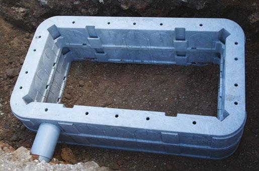
At least 5 sections are needed to meet the minimum box depth of 750mm.
Duct entries can be cut as and where required using a hole saw mounted on a cordless drill.
The chambers incorporate guides which identify drilling points to ensure correct duct spacing.
A maximum of 4 duct entries can be made into a single wall of the Quadbox™.


If the frame requires levelling to the ground surface, or to a newly raised surface level, rising frame units (as shown) are available as an option. These should be used in conjunction with mortar to build the frame up to the required level. Where levels mean that the cover needs raised by more than the 50mm allowable mortar bed, bricks, quarry tiles etc. should not be used to adjust the height of the cover.
A further Quadbox section should be cut horizontally (minimum depth to be a 40mm wall section), with the voids of the cut chamber filled with C32/C40 concrete or mortar.
As with brick built chambers, care should be taken to make sure:
• The box is set at the correct depth and the base/plinth is installed correctly.
• The side wall is not damaged/misshapen due to over compaction.
• The frame is level with the surface and a core drill is used for cutting duct entries.
• The wall bearers are provided by Openreach and can be ordered by your FBC.
Joint box designs and specifications may vary depending on the duct layout and whether multi-way ducts or major road crossings need to be incorporated into the network design.
Full technical drawings and specifications for all joint and footway boxes can be found at openreach.com/fibre-broadband/fibre-fordevelopers/guides-and-handbooks
Materials
• Bricks: BS EN771-1. Stretcher Bond.
• Cement: BS EN197-1:2000 ordinary mix. Three parts sand to one part cement.
Specifications
• Base: 150mm concrete, clean and level.
• Brickwork: Keyed in at the corners and pointed.
• Frame and cover: Set on a mortar bed and fitted squarely to the box structure. You can purchase lifting keys for the covers from TW Engineering Co Ltd at www.twtools.co.uk (tel: 0115 932 3223).
• Duct entries: Must not enter through corners and be no less than 75mm from the side wall. They shall enter wall at a minimum depth of 250mm from the top of the frame, cut flush and clear the base by a minimum of 100mm.
• Bolts: Must be fitted in each box to allow ironwork to be installed by the developer.
• Step(s): One step is required in all boxes deeper than 700mm.
• JBF104(C): 915mm(L) x 445mm(W) x 750mm(D).
• JBF104(D): 915mm(L) x 445mm(W) x 900mm(D) the minimum depth for boxes either side of road crossings.
• JBF106(C): 1310mm(L) x 610(W) x 750(D).
• JBF106(D): 1310mm(L) x 610(W) x 900(D) the minimum depth for boxes either side of road crossings.
• All backfill material to be class 6N type.
• Workmanship, materials and method of construction are to comply with all current relevant contract documents, British Standards and codes of practice for the construction industry.
• Concrete to be grade C32/40 with a water cement ratio 0.4 minimum. Cement content 380kg/m3. Aggregate maximum size 20mm. All in accordance with BS8500.
• All ducts shown are based on maximum recommended values for Duct Type 54D.
• End ducts to be inline.
• Ducts to be positioned not less than 75mm from a side wall.
• Mesh to be grade B500B or B500C conforming to BS4483.
• Short lengths of Duct 54D 90mm to be used on non-ducted routes. Appropriate duct to be used on ducted routes.
• Where instructed to do so drill one set of three holes using a 12mm masonry drill bit to a depth of 80mm for future fitting of equipment mounting bracket.
• For details and specs on using corbelling visit the link at the top of this page.
Please note
At no time must minimum box depth be compromised. Consult your FBC if the minimum depth cannot be achieved.
Joint boxes, footways and frames & covers
Internal dimensions. Brickwork Stretcher Bond.
Dimensions in mm (not to scale).
• Maximum depth 900mm
Bolts foundation for wall bearer/brackets
boxes, footways and frames & covers
Internal dimensions. Brickwork Stretcher Bond. Dimensions in mm (not to scale).
• Minimum depth for road crossing 600mm
• Sump to be fitted in boxes deeper than 700mm
Bolts foundation for wall bearer/brackets
Full technical drawings and specifications for all carriageway boxes can be found at openreach.com/fibre-broadband/fibre-for-developers/guides-and-handbooks
Materials
• Bricks: Minimum Class B Engineering Bricks, BS EN1996
• Cement: BS12:1996 – Specification for Portland cement
• Concrete: C35/45, BS EN206
• Mortar: Class (iii), 1:5 CEMENT:SAND ratio (max) or 1:1:5 CEMENT:LIME:SAND
Base
• Cement: BS12:1996 – Specification for Portland cement
• Concrete: 1 layer of A393 mesh to top face of base slab. Minimum 55mm cover to any face. B500B or B500C, BS4483
Brickwork
• English bond, flush pointed
Frame and cover
• Frame cover to be installed to DMRB CD534 installation practices Lifting keys
• Key Joint Box Lifter should be used to lift the cover and can be purchased from TW Engineering Co Ltd at www.twtools.co.uk (tel: 0115 932 3223) or similar supplier of your choosing
• Duct to be cut flush to the internal box wall
• Duct must not enter through corners and be no less than 75mm from the side wall
• Duct to enter wall no less than 450mm from the top of the frame
Cubis Industries is the only supplier of these Openreach approved products.
Only approved frames and covers shall be fitted on your site. They are identifiable by the following markings; ‘EN24 B125’ the British Standards kitemark the Manufacturer Mark (SID), the year of manufacture and the BT identifier.
The ‘standard frames and covers’ are supplied by Openreach. They consist of a galvanised steel fabricated frame, fitted with unfilled galvanised steel fabricated cover trays and cross-beams.
All covers can be fitted to brick or concrete.
Please note
Where there’s evidence or high risk of vehicles using the soft verge e.g. as an undertaking area opposite a T-Junction, a passing point on a narrow road or a parking area, it will be necessary to install a ‘carriageway chamber, frame and cover’. There is also an optional ‘recessed frame and cover’.
These can be purchased by the installer as an option to the ‘standard frame and cover’.
Each cover tray has two key-hole fittings (in the centre of the short side) one of which carries a BT identity mark and the manufacturers’ three letter identification ‘SID’. The other key-hole fitting displays EN124 and B125 together with the BSI Kite mark certifying the covers to BS EN124: 1994. Recessed frames and covers will accommodate infill blocks to a maximum depth of 60mm. If you’re planning to install frames and covers that aren’t supplied by Openreach e.g. for block paving, or you have any doubts about what frames and covers to use, please speak to your FBC.

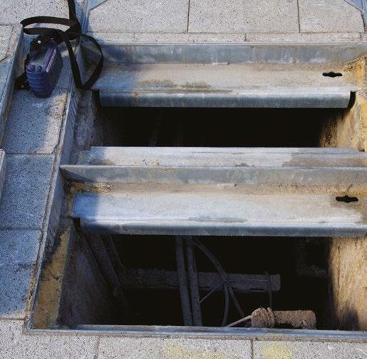
All frames and covers shall be levelled to the final running surface. Where a box is located within grass, soft or unmade surfaces, the frame shall be surrounded with a 100mm wide strip of minimum grade C25/30 concrete, to the full depth of the frame, finished level with the top edge of the frame and the outside edge. It must be straight and parallel to the frame.
Unapproved frames and covers must not be fitted. Openreach will take any necessary action against any developer who fits unapproved frames and covers within the network, including any potential claim for damages and costs, with possible delayed Service On Demand (SOD) payments. If you’re unsure how to specify approved covers, please contact your FBC.
If your site has shared surfaces for roads and footways, please ensure the correct joint box is installed based on the following guidelines.
• There must be a defined kerb line between the road and footway to install a footway spec box or modular quadbox in the footway area
• If no defined kerb line is present, a carriageway spec box must be installed as regular traffic could pass over these areas
• Driveways attached to houses and entrances to service areas do not require a carriageway spec box, so footway and modular quadboxes can be used for these areas
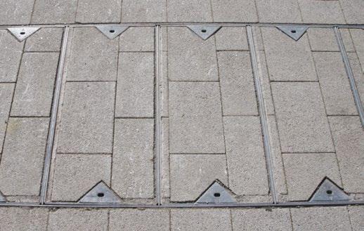

Defined kerb line separating road and footway
Carriageway box required in this area
Example of a defined kerb line on a shared surface
Openreach maintains that all reasonable care and skill has been used in the compilation of this publication. However, Openreach shall not be under any liability for loss or damage (including consequential loss) whatsoever or howsoever arising as a result of the use of this publication by the reader, his servants, agents or any third party.
In the event of a discrepancy between the contents of this document and the contract, the terms and conditions shall take precedence. This is a living document and will be subject to update and change. The information within this document is provided for information purposes only. The Contract and Price List takes precedence.
BSI British Standards Institute
BT British Telecommunications
CLI Customer Lead In
CP Communications Provider
DP Distribution Point
FDP Fibre Distribution Point
FTTP Fibre to the Premises
FBC Field Based Coordinator (formally New Site Representative)
HDPE High-Density Polyethylene
IET Institute of Engineering and Technology
JBC (N) Joint Box Carriageway New Sites
JBF Joint Box Footway
LSZH Low Smoke Zero Halogen
MDU Multiple dwelling unit
MJF Product code designation for the Cubis Industries–StakkaBox/Quadbox
M&E Mechanical & Electrical
NJUG National Joint Utilities Group
NTE Network Terminating Equipment
NTP Network Terminating Point
ONT Optical Network Termination
PAS Publically Available Specification
PE Polyethylene
PVC Polyvinyl Chloride
RFH Reduced Fire Hazard
SID Manufacturers three letter identification
SDU Single dwelling units
SOD Service on Demand
UG Under Ground
This guidance is a practical aid for designers and site workers on what to eliminate, avoid and consider when working on the Openreach network on your site.
The advice is not exhaustive so speak to your Field Based Co-Ordinator (FBC) if you need further information.
Hazardous procedures, products and processes that should be eliminated from the project where possible
Distribution point (DP) location
• Placing DPs into voids or other enclosed spaces with inadequate ventilation.
• Placing DPs adjacent to, or above, any fragile surface.
• Placing DPs directly above, or adjacent to, water features/courses etc.
• Locating DP at greater than 1.5 meters above finished floor level (without fixed access system incorporated into design).
Power systems
• Ensure all power installation meets relevant standards, and where DC supplies are planned seek further advice about requirements for earthing of racks, power supply ratings etc. to take account of future needs and growth.
Cabling routes and lead-ins
• Routing of cables where the cables are above head height within false ceiling systems without a proper access system incorporated.
• Routing of cables external to building requiring specialist access methods (scaffold, mobile elevating work platform etc.)
• No internal ducting laid into single dwelling units (SDUs).
Aerial and antenna transmission/ receiver systems
• Not mounted on building walls or other difficult to reach areas of a building.
• Design of roof mounted services that require access (for maintenance and so on), without provision for safe access (such as barriers) in particular access for aerials/antennas systems.
Joint boxes, footways and frames & covers
Products, processes and procedures to be eliminated or reduced as far as possible and only specified or allowed if unavoidable. Including amber items would always lead to the provision of information to the principal contract or contractor where only one contractor has been appointed.
Distribution point (DP) location
• DPs located into voids or enclosed spaces provided with ventilation systems built in.
Aerial and antenna transmission/ receiver systems
• EMF exclusion zones adequately managed with fixed barriers or partitioning systems.
Cabling routes and lead-ins
• Routing of cables where the cables are above head height within false ceiling systems.
• Routing of cables internally where access points require use of access equipment (ladders, step-ladders or platform steps) to allow for pulling in of cables.
Products, processes and procedures to be positively encouraged.
• Adequate access for vehicles to minimise reversing requirements (one-way systems and turning radii) in particular if specialist vehicles will need access (pole erection units, MEWP vehicles etc.).
• Provision of adequate access and headroom for maintenance in communications rooms, and adequate provision for replacing heavy components.
• Thoughtful location of mechanical and electrical equipment, such as telecoms equipment, termination points, Wi-Fi transceivers etc. and so on to facilitate access, and placed away from crowded areas.
• Lighting within communications rooms adequate for fine tasks (fibre splicing, small diameter copper wire terminations etc.)
• Provision of adequate air handling/ conditioning and ventilation for the installed equipment base within the communications room (and people having to access and work within the area).
• Early installation of permanent means of access, and prefabricated access systems with hand rails.
• Provision of edge protection at permanent works where there is a foreseeable risk of falls after handover (consider radio antenna or aerials installations on roof spaces).
• Encourage the use of engineering controls to minimise the use of personal protective equipment.
To help make sure your site network is built to a high quality standard, we’ve produced a checklist for each phase of the build. Your FBC will complete an online version of this checklist at each stage, this list can be used as a reference.
Any subsequent changes to the site plan after stages have been signed off must be communicated and agreed with your FBC as soon as possible.
Any re-work as a result of an out of date site plan could cause delivery delay and incur you costs in time related charges.
If you have any questions about your development, please visit: openreach.com/fibre-broadband/fibre-for-developers or call us on 0800 783 2023
Item being audited
Base has been cast correctly.
Reinforced base cast correctly for Joint Box Carriageway JBC (N).
Bearers and brackets fitted. Steps fitted where appropriate.
Bolts fitted and positioned correctly during construction of boxes.
Joint Box constructed to correct dimensions and installed at the correct depth. Any deviations to plan recorded and signed off.
All concrete/brickwork carried out as per developer ‘How to’ guide specification.
Cement and brick types used as specified or exceptions agreed and documented.
Frames and covers bedded and correctly installed (if unmade surface, Joint Box frame secured).
Joint Box constructed as planned, positioned correctly and conforms to drawings. Alternatives agreed and documented.
Modular box installed and prepared as per instructions.
Ducts properly trimmed and keyed when set in walls.
External cable/Blown Fibre Tubing (BFT) protected and sealed in Joint Box.
Joint Box
Joint Box
Joint Box
Joint Box
Joint Box
Joint Box
Joint Box
Joint Box
Joint Box
Joint Box
Joint Box
Joint Box
Fibre cable and draw rope provided in sound condition and correctly jointed where applicable.
Duct
Cable/BFT left in planned location. Duct
Correct rope/cables/tubing installed as per developer ‘How to’ guide.
Duct
Correct type of duct provided and used. Duct
Duct laid in required position, at correct depth and installed in the correct position in the Joint Box.
Duct properly trimmed and keyed when set in walls.
Duct separation distance maintained, or exception agreement obtained and documented.
Ducts laid at minimum depth (250mm), or exceptions agreed and documented. (To be viewed in footway where possible, if not check via Joint Box).
Joint Box constructed as planned, positioned correctly and conforms to drawings. Alternatives agreed and documented.
Temporary duct seals fitted to agreed standard.
Ducts positioned correctly on external walls and in line with the cable entry point.
Duct
Duct
Duct
Duct
Duct
Duct
Duct
Quality control checklist
Item being audited
Category
Ducts positioned in line with the cable entry point. Plot
Customer cable entries correctly positioned and provided. Plot
External cable/BFT protected and sealed. Plot
Duct seal Plug 1A fitted. Plot
Back box installed at entry point. Plot
Back box fitted at a usable depth, within close proximity to a double 240v outlet for FTTP services. Plot
Location of unit entry point suitable for FTTP equipment. Plot
The property has been designed to accommodate voice and data wiring in a convenient place for home owners to use FTTP services. Plot
A permanent 240 volt supply is required for FTTP. Developer has been informed that no orders can be made or taken via a communications provider until all installation works of Openreach equipment into each plot has been completed and tested. Plot
Voice and data cabling provided and terminated correctly for FTTP services. Plot
If FTTP self install development ONT, all leads connected correctly and plot commissioned. Plot
If self install not completed and Openreach completes all internal work then SOD payment for self install is not applied. Plot
All tubes or cables presented as per schematic diagram and capped. Multi dwelling unit
Designated track ways/trays supports in good working order with separations maintained.
Connectorised fibre cable installed as per schematic in accordance with manufacturer’s specifications and IET wiring regulations. Cable labelled and coiled safely within riser.
Connectorised fibre cable installed with 1m of spare length protruding from the back box to enable jointing.
Back box fitted in each unit at a usable depth, within close proximity to a double 240v outlet for FTTP connectivity.
Location of unit entry suitable for FTTP equipment.
If FTTP self install development ONT, all leads connected correctly and plot commissioned.
If self install but Openreach completed all internal work then SOD payment for self install is not applied.
Multi dwelling unit
Multi dwelling unit
Multi dwelling unit
Multi dwelling unit
Multi dwelling unit
Multi dwelling unit
Multi dwelling unit
PIA allows non-Openreach network providers to share Openreach’s network infrastructure, which on Full Fibre new sites consists mainly of ducts and chamber boxes. PIA can also be used to share telegraph poles as well as underground infrastructure.
PIA allows multiple network providers to deliver service on a new site development without requiring different ducts and chamber boxes for each service.
Non-Openreach network providers will have to be invited onto site by you as a developer to be a part of a PIA delivery, Openreach is unable to provide this initial contact. If you have a nonOpenreach network provider interested in a PIA product, inform your Openreach FBC and they will guide you through the following steps.
• An initial site meeting between you the developer, your Openreach FBC and the nonOpenreach network provider will be completed to discuss the PIA proposal
• Your FBC will share the required quality standards with you the developer and the nonOpenreach network provider
• Your FBC will perform a series of checks to ensure the non-Openreach network provider has various requirements in place to allow the PIA product to be legally used
• Your FBC will confirm when the duct and chamber box work has been completed to allow the non-Openreach network provider to install their equipment
Please ensure your FBC is made aware of any non-Openreach network planned to be installed on site during your initial site visit to allow the above process to be followed.
More information about PIA can be found on the Openreach website: openreach.co.uk/cpportal/products/passive-products/physical-infrastructure-access(PIA)
Notes
The telecommunications services described in this publication are subject to availability and may be modified from time to time. Services and equipment are provided subject to British Telecommunications plc’s respective standard conditions of contract. Nothing in this publication forms any part of any contract. Openreach and the Openreach logo are trademarks of British Telecommunications plc.
© British Telecommunications plc 2022. Openreach Limited. Registered office: Kelvin House, 123 Judd Street, London WCIH 9NP. Registered in England and Wales no. 10690039. Produced by Openreach. Designed by Westhill.co.uk
PHME 87500
Modern commercial sites require network ready for the demands of connected businesses. Openreach provides your commercial developments with a modern platform for businesses to enable the connectivity they need, using the provider of their choice through our unrivalled open-access network.

Our full fibre network delivers ultrafast speeds and varied connection options depending on the type of site being built. From multinational distribution hubs to sole traders working from home, Openreach full fibre networks power business connectivity across the country.
Ensure your commercial site is ready for connection with no delays
When connecting a new commercial development to Openreach infrastructure, much of the work is done off-site. Bringing the network from the telephone exchange to your site can require passing through city centres, motorways, or other developed areas. It can take weeks or months to get planning permission alone for these areas, causing huge delays if not prepared. Our Network in Advance (NIA) service can help deliver key network infrastructure off-site before a formal order is placed. Our commercial specialists and project managers will work with you at the earliest stages of your development, providing a full plan and works to deliver network to the edge of your site as early as possible.
Shorten lead times on remote sites by building the off-site infrastructure as soon as possible
Prevent delays due to other work being performed in areas where Openreach infrastructure must be installed
Ensure complex, city centre sites are connected in time by early planning of traffic and other civil permissions
The right network type for your site and the businesses you work with
Ethernet offers everything a modern business could need for their network solution. From small companies reliant on e-commerce for revenue to multinational corporations working on cloudbased systems. Ethernet delivers a dedicated cable straight from the exchange into a single business property. There’s no shared network so ultra-low latency is guaranteed. This dedicated line allows speeds more than 10 times faster than our standard Fibre to the Premises offering.
FTTP is our standard full fibre option. It’s affordable and reliable, using the same network technology as an FTTP home connection. It delivers all the key benefits of fibre technology. FTTP is a pure fibre connection that runs from the exchange to the edge of your development, where it can deliver service to a single unit or be split to deliver shared service to several smaller businesses.
Shared fibre connection to the telephone exchange can affect bandwidth during busy periods Connection
Dedicated symmetrical connection means no bottlenecking of speed in busy periods and equal upload and download speeds
Dedicated connection can handle speeds of up to 100Gbps depending on the product and communication provider
Up to 1Gbps, with 330Mbps a common retail offering from communication providers
Guaranteed ultra-low latency, vital for real time applications and essential business services
Variable depending on connection and environmental factors
Business grade SLA – typically 5 hours or less depending on communication provider product
Variable by communication provider product, but typically next working day
Option 1: A single connection routed through two different cables, allowing switching of paths if one is damaged
Option 2: Two circuits connected to different areas of the end site. Allows for different connection options on each circuit
SME and corporate companies dependent on high bandwidth connectivity, usually due to businesscritical VPN, real time data transfer or network dependent applications
Energy sector, distribution centres, blue-chip tech tenants, backhaul 4G/5G and large public WiFi
None
Consumer and SME businesses where monthly network costs are a key factor, but who still required high quality connectivity
Residential and many businesses including small offices, sole traders

We’re the UK’s network provider, and we’re committed to delivering the fastest, highest quality broadband network across the country.
We’ve invested over £14 billion into our network in the last 10 years, providing ultrafast Full Fibre to millions of homes and businesses.
Choice is essential to a business, and our wholesale network will give your business tenants a wide range of choices for their broadband provider.
If you’re building a site with 20 or more commercial units, we’ll provide FTTP for free.
For sites with fewer than 20 plots our competitive rate card provides an affordable option for fibre connectivity. We’ll also contribute to the cost, with an amount provided per premises.
Once you’re ready to place your order, or if you just want to discuss the options available, visit our website and get in touch. openreach.co.uk/propertydevelopments

MountbattenHouse,BasingView,Basingstoke,Hampshire,RG214HJ

Advice:HSL-240816134455-411DoesNotCrossAnyConsultationZones
YourRef:LewishamShoppingCentre DevelopmentName: Comments:

Theproposeddevelopmentsitewhichyouhaveidentifieddoesnotcurrentlyliewithintheconsultation distance(CD)ofamajorhazardsiteormajoraccidenthazardpipeline;thereforeatpresentHSEdoesnot needtobeconsultedonanydevelopmentsonthissite.However,shouldtherebeadelaysubmittinga planningapplicationfortheproposeddevelopmentonthissite,youmaywishtoapproachHSEagainto ensurethattherehavebeennochangestoCDsinthisareaintheinterveningperiod
ThisadvicereporthasbeengeneratedusinginformationsuppliedbyAndrewSmithatWSPGroupon16 August2024.

