ENERGY STRATEGY AND OVERHEATING STATEMENT


Lewisham Shopping Centre
Energy Strategy and Overheating Statement
LSC-WSP-XX-XX-RP-EY-000001
October 2024
TABLE
TABLE 1-2
TABLE 1-3
TABLE 1-4
TABLE 1-5
TABLE
TABLE 2-1
TABLE 2-2
TABLE
TABLE
TABLE 3-2 BASELINE REGULATED AND UNREGULATED CARBON EMISSIONS OF THE SCHEME –
TABLE 3-3 BASELINE REGULATED AND UNREGULATED CARBON EMISSIONS OF THE SCHEME – PHASE 1A................................................................................................................................12
TABLE 3-4 BASELINE REGULATED AND UNREGULATED CARBON EMISSIONS OF THE SCHEME –
TABLE
TABLE 4-2 HVAC SPECIFICATION
TABLE
TABLE
TABLE
TABLE 4-6 BE LEAN: CARBON EMISSIONS AFTER THE APPLICATION OF ENERGY EFFICIENCY MEASURES – PHASE
TABLE 4-7 BE LEAN: CARBON EMISSIONS AFTER THE APPLICATION OF ENERGY EFFICIENCY MEASURES – THE OUTLINE SCHEME .......................................................................................15
TABLE 4-8 FABRIC ENERGY EFFICIENCY AND CARBON EMISSIONS
TABLE
TABLE 5-2 SUMMARY OF SCENARIOS CONSIDERED FOR LTHW DISTRIBUTION................................................................................................................................................................................17
TABLE 5-3 ANNUAL HEATING DEMAND CALCULATED FOR THE PROPOSED DEVELOPMENT...........................................................................................................................................................18
TABLE 5-4 BE CLEAN: CARBON EMISSIONS AFTER THE APPLICATION OF ENERGY EFFICIENCY MEASURES
TABLE 5-5 BE CLEAN: CARBON EMISSIONS AFTER THE APPLICATION OF ENERGY EFFICIENCY MEASURES –
TABLE 5-6 BE CLEAN: CARBON EMISSIONS AFTER THE APPLICATION OF ENERGY EFFICIENCY MEASURES –
TABLE 5-7 BE CLEAN: CARBON EMISSIONS AFTER THE APPLICATION OF ENERGY EFFICIENCY MEASURES – THE OUTLINE SCHEME.....................................................................................19
TABLE 6-1 COMPARING ESTIMATED HEATING AND HOT WATER COSTS FOR TENANTS..................................................................................................................................................................21
TABLE 6-2 BE GREEN: CARBON EMISSIONS AFTER PROVIDING RENEWABLE ENERGY – RESIDENTIAL.........................................................................................................................................21
TABLE
TABLE
TABLE
TABLE 9-4
TABLE 9-5
TABLE 10-1
TABLE
TABLE
TABLE 10-4
TABLE
TABLE
TABLE
TABLE 10-8
TABLE 10-9
TABLE 10-10
TABLE 10-11
TABLE 11-1
TABLE 11-2
HIERARCHY, PROJECT MEASURES AND PROJECT PERFORMANCE/SIMULATION
FIGURE 1-1 SITE
FIGURE
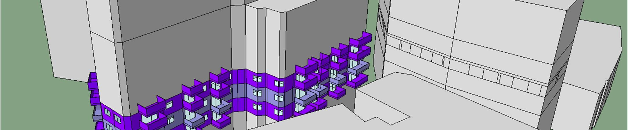
FIGURE 3-1 RENDER OF THE IES MODELS AND THE APARTMENT SELECTION USED IN THE SAP CALCULATIONS OF THE PROPOSED DEVELOPMENT N1......................................................10
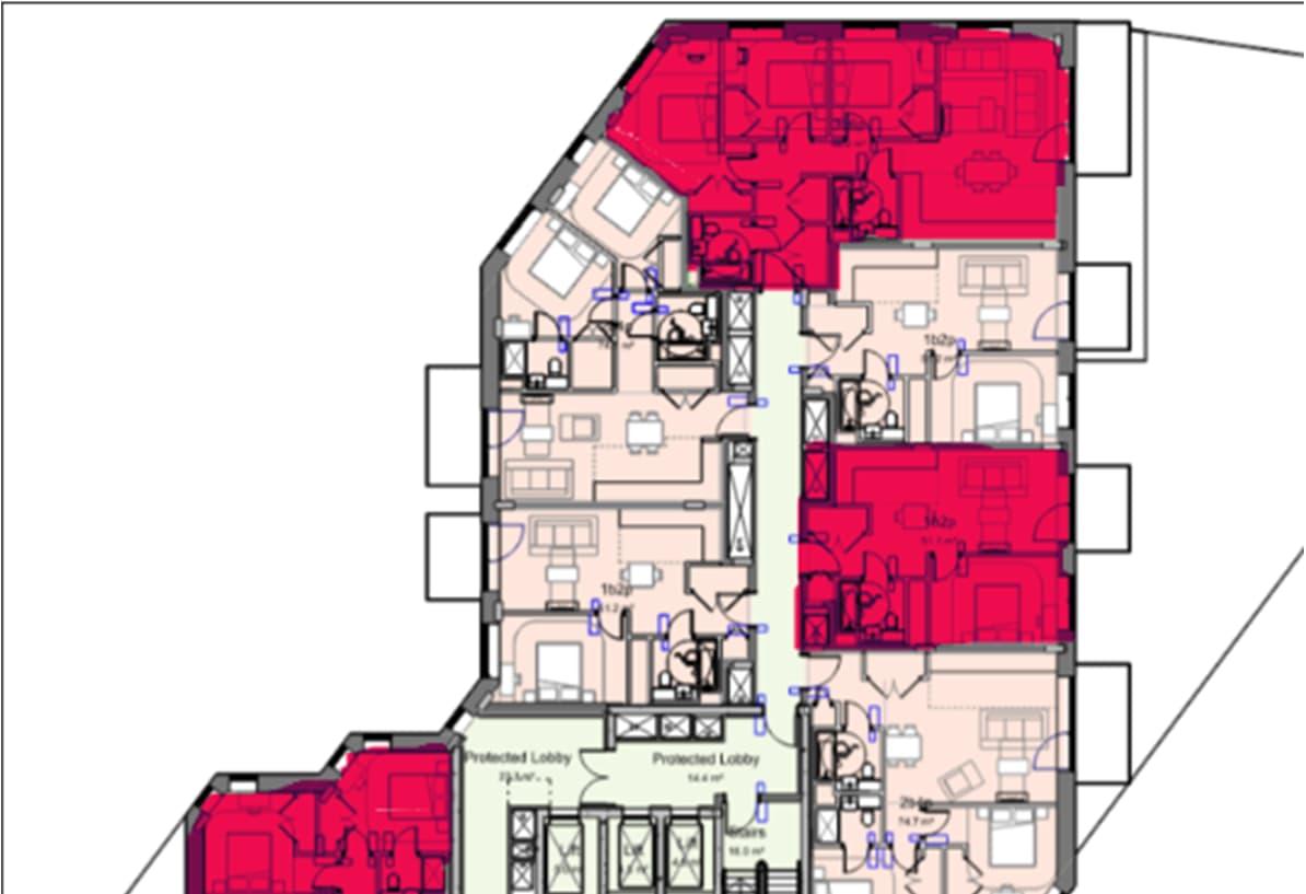
FIGURE 3-2 RANGE OF APARTMENTS MODELLED IN SAP CALCULATION PROCESS N1. (RED = SELECTION OF APARTMENTS MODELLED IN SAP CALCULATION)..........................................10
FIGURE 3-3 RENDER OF THE IES MODELS AND THE APARTMENT SELECTION USED IN THE SAP CALCULATIONS OF THE PROPOSED DEVELOPMENT N2......................................................11
FIGURE 3-4 RANGE OF APARTMENTS MODELLED IN SAP CALCULATION PROCESS N2 (RED = SELECTION OF APARTMENTS MODELLED IN SAP CALCULATION)...........................................11
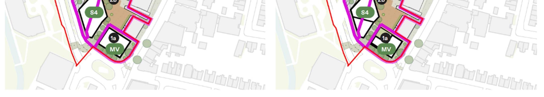
FIGURE 5-1 EXCEPT FROM THE LONDON HEAT MAP SHOWING ANY EXISTING (RED) AND PROPOSED (PURPLE) DISTRICT HEATING NETWORKS, SITE SHOWN IN BLUE.............................16
FIGURE 5-2 HEAT GENERATION PLANT AND NETWORK LAYOUT FOR THE PROPOSED SCENARIOS................................................................................................................................................17
FIGURE 5-3
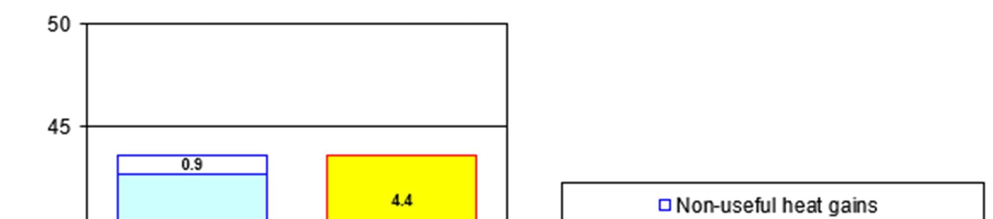
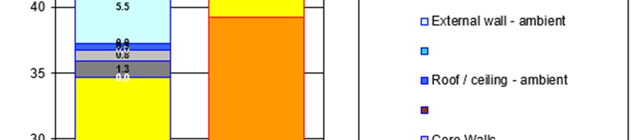
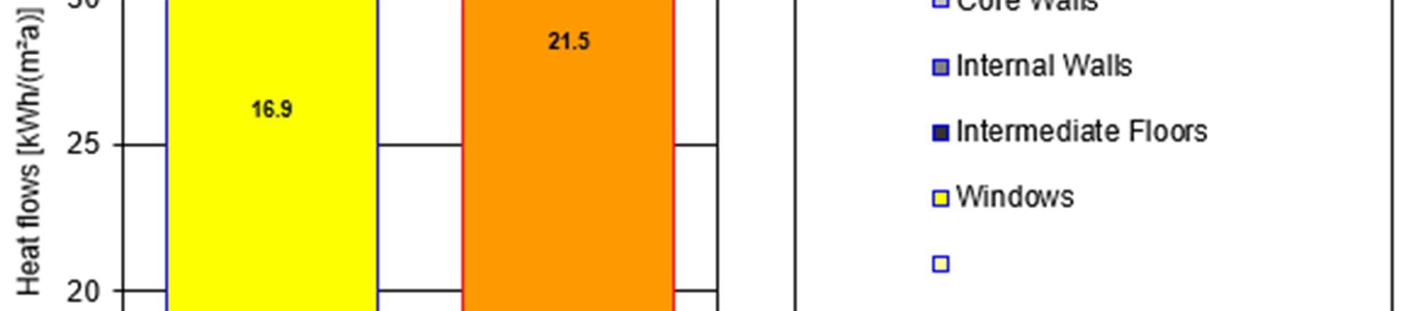
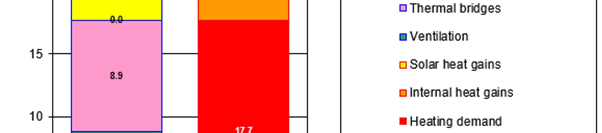
FIGURE 7-1 ENERGY BALANCE EXTRACTED FROM PHPP, N1 (LEFT) & N2
FIGURE
FIGURE
FIGURE
FIGURE
FIGURE
This Energy Statement has been prepared by WSP on behalf of Landsec Lewisham Limited (‘the Applicant’) in support of an application for hybrid planning permission for the redevelopment of Lewisham Shopping Centre (‘the Site’) within the London Borough of Lewisham. The description of development is as follows and will be referred to as ‘the Proposed Development’:
Multiple layers of statutory and policy requirements apply to the Proposed Development at a national, regional and local level, each of which requires different energy efficiency and carbon emission targets to be met. The Proposed Development is designed to meet and exceed key energy and carbon performance targets across all building uses, showcasing a strong commitment to sustainability, operational efficiency, and alignment with local and national policy objectives.
The Applicant’s approach to sustainable development is underpinned by policies from the London Plan and Lewisham Local Plan. Together these documents provide spatial policies, development management policies and site allocations to guide and manage development in the London Borough of Lewisham.
A Hybrid Planning Application is being submitted for the Proposed Development, with Detailed Planning Permission sought for parts of Phase 1a (Plots N1, N2 and surrounding spaces), as well as shopping centre interface and highway access works; and Outline Planning Permission sought for the remainder of the scheme.
Full planning application (within Phase 1a) comprising the demolition of existing buildings, structures and associated works to provide a mixed-use development including the erection of a Co-Living building (Sui Generis) up to 23 storeys in height (Plot N1), and a residential building (Class C3) up to 15 storeys in height (Plot N2), associated residential ancillary spaces as well as town centre uses (Class E (a, b, c, d, e, f, g (i, ii)); and Sui Generis) together with public open space, public realm, amenity space and landscaping, car and cycle parking, highway works and the formation of new pedestrian and vehicle accesses, existing shopping centre interface works (the ‘Phase 1a Finish Works’), service deck modifications, servicing arrangements, site preparation works, supporting infrastructure works and other associated works.
Outline planning application (all matters reserved) for a comprehensive, phased redevelopment, comprising demolition of existing buildings, structures and associated works to provide a mixed-use development including the following uses:
Living Uses, comprising residential (Class C3) and student accommodation (Sui Generis);
o Town Centre Uses (Class E (a, b, c, d, e, f, g (i, ii) and Sui Generis));
o Community and Cultural uses (Class F1; F2; and Sui Generis);
o Public open space, public realm, amenity space and landscaping works;
Car and cycle parking;
Highway works;
Formation of new pedestrian and vehicular accesses, permanent and temporary vehicular access ramps, service deck, servicing arrangements and means of access and circulation within the site;
Site preparation works;
Supporting infrastructure works;
Associated interim works;
Meanwhile and interim uses and other associated works.
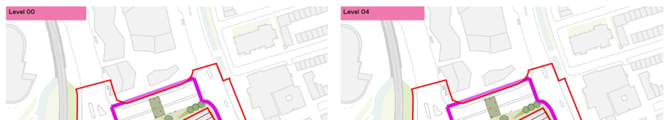
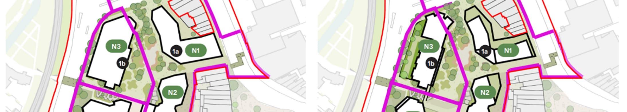
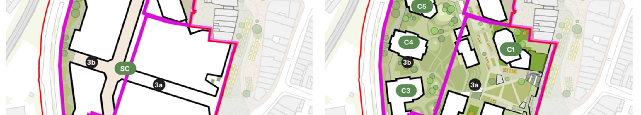
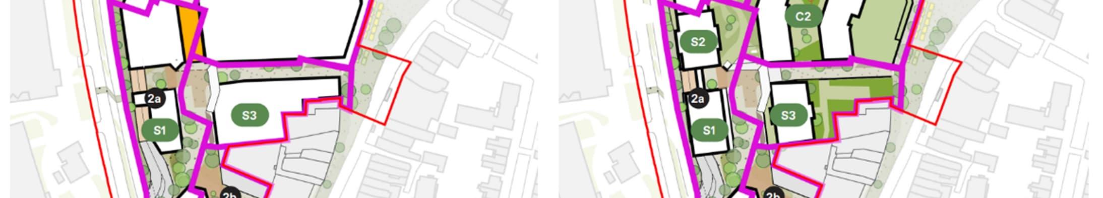
Based on latest accommodation schedule provided by SEW the buildings will be constructed in the following phases as described by Figure 1-1.
Table 1-1
Table 1-2
1
This report should be read in conjunction with all other consultants’ reports and specifications, sketches, drawings, and design development notes (DDNs). 1
The Proposed Development aims to exceed the relevant energy and carbon reduction targets for both residential and non-residential components, demonstrating a commitment to sustainable design and long-term environmental responsibility.
All developments must meet the prevailing Building Regulations requirements. Specifically, with regards to energy and carbon compliance, all buildings must meet the Building Regulations Part L ‘Target Emission Rate’ (TER) requirements for the Part L revision which is current at the time of initial construction works for each developmental phase. The Proposed Development will be brought forward under Part L 2021, which will be used as the basis of the energy strategy.
The residential components of the Proposed Development will be assessed against Approved Document L1A (AD L1A) which relates to new build residential buildings and all the non-residential components will be assessed against Approved Document L2A (AD L2A) relating to new build non-residential buildings.
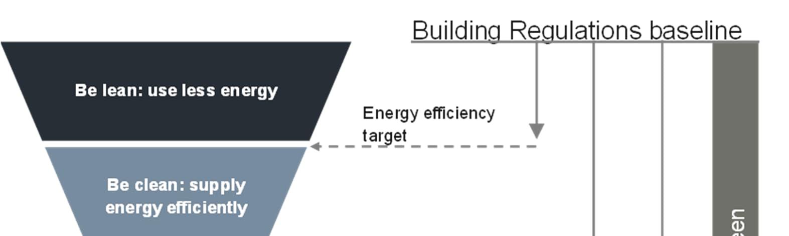
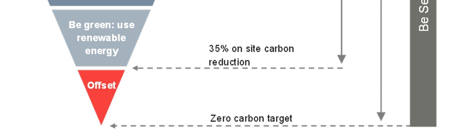
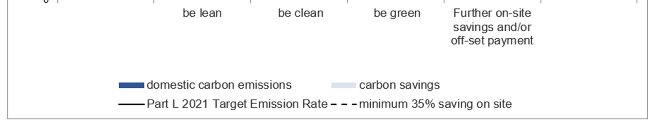
As required by The London Plan, the residential components of the Proposed Development must demonstrate how the zero-carbon target for both residential and non-residential developments will be met, with at least a 35% on-site reduction beyond Part L 2021 and proposals for making up the shortfall to achieve zero carbon, where required. For the purposes of calculating carbon reductions for planning the Part L 2021 emission factors will be used.
Residential developments should target a 10% improvement on Building Regulations from energy efficiency.
Non-residential developments should target a 15% improvement on Building Regulations from energy efficiency.
Developments will be required to connect to or demonstrate a potential connection to a decentralised energy system unless it can be demonstrated that it is not feasible or viable and evaluate the feasibility of communal heating systems.
Major developments should provide a reduction in expected CO2 emissions through the use of on-site renewable energy generation, where feasible to do so.
Dynamic modelling for overheating risk analysis in line with the guidance and data sets in Building Regulations Part O ‘Overheating’, CIBSE1 TM52 ‘The limits of thermal comfort: avoiding overheating’ and TM59 ‘assessment of overheating risk in homes’ should be undertaken.
The Energy Statement must include information of how the building’s actual energy performance will be monitored post-construction and produce all relevant documentation as outlined in the “Be Seen – Energy Monitoring Guidance”.
All major developments are required to calculate and reduce the whole life-cycle carbon (WLC) emissions to fully capture the development’s carbon impact.
The energy strategy has been structured in accordance with Greater London Authority (GLA)’s energy hierarchy: Be Lean, Be Clean, Be Green and Be Seen. The Proposed Development aims to achieve energy efficiency and sustainability throughout.
The Proposed Development will be designed to achieve optimum energy performance, and will incorporate the following design features:
During design development, significant consideration has been given to how the building fabric will respond to its environment in order that the energy consumption of the building is reduced as far as possible through passive means. The building fabric will be designed to exceed the minimum fabric requirements of Part L1 and L2 (2021) of the Building Regulations.
Passive design measures will be incorporated into the design to reduce energy demand and the risk of overheating.
A high-performance building services solution is proposed for the Proposed Development.
The Applicant has coordinated and collaborated with The London Borough of Lewisham, on connecting to the proposed Lewisham Town Centre Heat Network, and with Eon on connecting to the existing Loam Pit Vale heat network. The proposed Lewisham Town Centre Heat Network is not due to be operational until after Phase 1 of the project has come online. The Existing Loam Pit Vale heat network currently has no additional heat capacity sufficient to supply the Proposed Development, and the available heat is high carbon, generated by CHP and gas boilers. Subsequently, connection to either heat network has not been deemed feasible for Phase 1, but will be considered for future phases of the project if appropriate. All energy centres will be designed for future connection into a district heating network through the provision of capped connections should a connection prove to be feasible.
There are 4 No. Multi-function Air Source Heat Pump Units located on the external roof level of N1 which provides heating and cooling to the building.
The heat pumps have been designed to use low GWP refrigerant R290, and operate efficiently. When providing cooling heat can be recovered to simultaneously supply heat to the building.
There are 3 No. CO2 Air Source Heat Pumps located on the external roof level of N1 which provides domestic hot water to the building.
The primary heating/cooling plant regulates an LTHW/CHW network. The LTHW and CHW serves fan coils in each residential apartment to provide space conditioning.
Each residential unit will be provided with a Mechanical Ventilation Heat Recovery (MVHR) unit. This will be located and ducted at ceiling level.
Terminal units are designed to achieve a specific fan power in operation significantly lower than the Part L 2021 limiting SFP.
All spaces will include 100% low energy lighting.
Available roof space will be maximised for the use of PV panels.
There are 2 No. Air Source Heat Pump Units located on the external roof level of N2 which provides heating and hot water to the building.
The heat pumps have been designed to use low GWP refrigerant R290, and operate efficiently supplying heat at 60 degrees.
The primary heating/cooling plant regulates an LTHW network serving HIUs in each residential apartment to provide space heating and hot water.
Each residential unit will be provided with a Mechanical Ventilation Heat Recovery (MVHR) unit. This will be located in a utility cupboard and ducted to the façade at ceiling level.
A small number of apartments require cooling due to acoustic constraints, in this case, cooling will be supplied by an active cooling coil within the MVHR unit. All apartments have been future proofed by allowing space in utility cupboards for cooling if required in the future.
Terminal units are designed to achieve a specific fan power in operation significantly lower than the Part L 2021 limiting SFP.
All spaces will include 100% low energy lighting.
Available roof space will be maximised for the use of PV panels.
The remaining phases will also be served via ASHPs located on their respective roof levels.
The primary heating plant regulates an LTHW network. The LTHW serves in-apartment HIUs which in turn provide heating and hot water.
The Proposed Development will be fully electric.
Terminal units are designed to achieve a specific fan power in operation significantly lower than the Part L 2021 limiting SFP.
All spaces will include 100% low energy lighting.
Commercial and amenity spaces will be completed to shell and core standard only, providing base services for future extension by tenants. The tenants will be responsible for provision of services to suit their particular requirements.
Subject to future legal and technical agreements, the development will be designed for future connection of each building into a district heating network through the provision of capped connections and future plant space should a connection prove to be feasible.
PV arrays are proposed on the roof of the proposed buildings to contribute towards the on-site carbon reduction target of 35% and the overall Zero Carbon Target. However, the size of the arrays will be limited due to space constraints from other plant located on the roof and green space required in order to achieve Urban Greening Factor targets.
Detailed energy modelling was undertaken based on the methodology from Part L1 and L2 of the Building Regulations in order to establish the baseline carbon emissions for the Plot N1 and Plot N2 (The detailed application site). These calculations would form the basis of the design for the remainder of the masterplan (outline application sites). Emissions for the outline element of the application site have been estimated based on detailed site application calculations by proportioning results from Plot N1 and N2 calculations to outline GIA areas for the remainder of the masterplan as shown in subsequent sections of this document.
WSP utilised a dynamic simulation software package, the Virtual Environment (VE) suite from Integrated Environmental Solutions (IES) to calculate the non-residential carbon emissions of The Proposed Development. The carbon emissions for the residential elements of the Proposed Development were calculated utilising Accredited Design Standard Assessment Procedure (SAP) 10software, Elmhurst Design. The SAP 10.2 carbon factors have been used for all further calculations using of the GLA 2021 Carbon Emission Reporting Spreadsheet version 2.0.
The results of the analysis for the residential element, and whole Proposed Development are shown in the tables below.
Table 1-2
– Residential
The tables above show the calculated CO2 emissions for Plots N1 and N2 (detailed application) at each stage of the energy hierarchy. The approach to the buildings in the outline element is intended to follow closely the principals established for the detailed element. Estimated CO2 emissions and associated savings after application of each stage of the energy hierarchy for the outline element are presented in the Table 1-2 below. The figures are obtained by proportioning the results from Plot N1 and N2 calculations based on the outline GIA areas for the outline element.
Table 1-5 Carbon emissions after providing renewable energy – The Outline Scheme
Table 1-3
The Proposed Development as a whole, including both the detailed and outline areas, aligns with the pertinent policies, including The National Planning Policy Framework, The London Plan, The Energy Assessment Guidance, The Lewisham Core Strategy Development Plan, London Borough of Lewisham Town Centre Local Plan, and The Building Regulations Part L.
Additionally, measures will be implemented to offset the remaining carbon emissions through a payment to the Council Carbon Offset Scheme.
During design development, fabric first approach has been taken and significant consideration has been given to how the building fabric will respond to its environment in order that the energy consumption of the building is reduced as far as possible through passive means. This has then been supplemented by highly efficient heating systems (ASHPs) to further reduce carbon emissions. Error! Reference source not found. shows the combined performance of residential and non-residential spaces. A site-wide (Detailed and Outline) carbon reduction of 76.2% over the Part L 2021 baseline has been achieved by the residential areas of the design.
Elmhurst Design SAP 10 software was used to determine the FEE standards for all apartments within plots N1 and N2 (detailed application area). An analysis has been undertaken on the new residential buildings within the detailed area to establish the performance of the fabric in relation to the TFEE. Results for TFEE and the Dwelling FEE (DFEE) for the detailed application buildings are as follows:
Table 1-6 Fabric energy efficiency and carbon emissions results
The approach to the façade design to the buildings in the outline element is intended to follow closely the principals established for the detailed element, as such all residential areas across the scheme, both in the detailed and outline areas achieve compliance with the TFEE standard. Detailed façade design and thermal bridging calculations will be performed during detailed design stage once junction details will be specified. The final strategy for compliance with TFEE will be defined as design develops. The project will ensure compliance with the TFEE is achieved.
Lewisham Council’s approach to sustainable development is underpinned by policies from the London Plan. Together these documents provide spatial policies, development management policies and site allocations to guide and manage development in the borough. Please note that references to these policies contained in this report are in summary form and do not purport to replicate these policies in full.
The National Planning Policy Framework (NPPF) was updated in December 2023 and replaces the previous versions. Plans and decisions should apply a presumption in favour of sustainable development.
The NPPF sets the planning context for sustainable design and construction. It is this that Local Planning Policies are based on and adapted to account for regionally specific requirements.
The NPPF identifies three dimensions to sustainable development - economic, social and environmental – which should be applied jointly and simultaneously:
Economic objective – to help build a strong, responsive and competitive economy, by ensuring that sufficient land of the right types is available in the right places and at the right time to support growth, innovation and improved productivity; and by identifying and coordinating the provision of infrastructure;
Social objective – to support strong, vibrant and healthy communities, by ensuring that a sufficient number and range of homes can be provided to meet the needs of present and future generations; and by fostering a welldesigned and safe built environment, with accessible services and open spaces that reflect current and future needs and support communities’ health, social and cultural well-being; and
Environmental objective – to contribute to protecting and enhancing our natural, built and historic environment; including making effective use of land, helping to improve biodiversity, using natural resources prudently, minimising waste and pollution, and mitigating and adapting to climate change, including moving to a low carbon economy.
The NPPF promotes the pursuit of sustainable development by seeking positive improvements to the built and natural environment, and to people’s quality of life. This will include:
Delivering a sufficient supply of homes
Building a strong, competitive economy
Ensuring the vitality of town centres
Promoting healthy and safe communities
Promoting sustainable transport
Supporting high quality communications
Making effective use of land
Achieving well-designed places
Protecting Green Belt land
Meeting the challenge of climate change, flooding and coastal change
Conserving and enhancing the natural environment
Conserving and enhancing the historic environment
Facilitating the sustainable use of minerals.
The London Plan was adopted in March 2021 and is the Spatial Development Strategy for Greater London. It sets out a plan for how London will be developed over the next 20-25 years.
An overview of the energy policy is provided in Table 2-1:
Table 2-1 Summary of key policies in the London Plan 2021
POLICY TITLE SUMMARY OF POLICY
Policy SI1: Improving Air Quality
Development should not lead to further deterioration of existing poor air quality, create any new areas that exceed air quality limits and create unacceptable risk of high levels of exposure to poor air quality.
Development must be at least air quality neutral and should use design solutions to prevent or minimise increased exposure to existing air pollution and make provision to address local problems of air quality in preference to post-design or retrofitted mitigation measures. Major development must be submitted with an Air Quality Assessment.
To reduce the impact on air quality during the construction and demolition phase development proposals must demonstrate how they plan to comply with the Non-Road Mobile Machinery Low Emission Zone and reduce emissions from the demolition and construction of buildings following best practice guidance
Policy SI2: Minimising Greenhouse Gas Emissions
Major development should be net zero-carbon. Reducing greenhouse gas emissions in operation and minimising both annual and peak energy demand in accordance with the energy hierarchy: Be Lean – Be Clean – Be Green – Be Seen.
Major development proposals should include a detailed energy strategy to demonstrate how the zero-carbon target will be met and achieve a minimum on-site reduction of at least 35% beyond Building Regulations.
Residential development should achieve 10% and non-residential should achieve 15% through energy efficiency measures.
Where it is clearly demonstrated that the zero-carbon target cannot be fully achieved onsite, any shortfall should be provided, in agreement with the borough, either: 1) through a cash in lieu contribution to the borough’s carbon offset fund, or 2) off-site provided that an alternative proposal is identified, and delivery is certain.
Major development should calculate and minimise carbon emissions from any other part of the development, including plant or equipment (Unregulated emissions).
Development (referable to the mayor) should calculate whole life-cycle carbon emissions through a nationally recognised Whole Life-Cycle Carbon Assessment and demonstrate actions taken to reduce life-cycle carbon emissions.
Policy SI3 Energy Infrastructure
Boroughs and developers should engage at an early stage with relevant energy companies and bodies to establish the future energy and infrastructure requirements arising from large-scale development proposals such as Opportunity Areas, Town Centres, other growth areas or clusters of significant new development.
Policy SI4 Managing Heat Risk Development should minimise adverse impacts on the urban heat island through design, layout, orientation, materials and the incorporation of green infrastructure.
Through an energy strategy, major development should demonstrate how they will reduce internal overheating and reliance on air conditioning systems in accordance with the cooling hierarchy.
The Mayor of London Energy Assessment Guidance sets out guidance on preparing energy assessments as part of planning applications. The document sets out the requirements to minimise CO2 emissions through the application of the energy hierarchy:
1. Be lean: use less energy;
2. Be clean: supply energy efficiently;
3. Be green: use renewable energy; and 4. Be seen: monitor performance.
To make use of the decreasing grid electricity carbon factor, due to the increased generation of electricity through renewable sources, this latest Guidance encourages the use of electric heating systems. This also fits with ambitions to improve air quality in London.
The Lewisham Core Strategy (LCS2) recognises Lewisham Town Centre as the borough’s most important commercial centre and its largest shopping area, and benefits from excellent public transport accessibility. It refers to the Council’s aspiration for Lewisham to achieve metropolitan town centre status through its potential for increased retail capacity and the provision of new housing, along with public realm and environmental improvements. The key energy related policies are summarised in Table 2-2:
Core Strategy Objective 5: Climate Change The council with its partners will take action to ensure that climate change is adapted to and mitigated against, including those measures necessary to create a low carbon borough and reduce carbon emissions by:
a) Promoting resource and water efficiency
b) Maximising generation and use of renewable energy and locally distributed energy, particularly for major development sites
c) Building to high standards of sustainable design and construction
d) Reducing waste generation
e) Supporting environmental protection and enhancement including establishing ecological networks
f) Minimising the environmental impacts of developments including water, noise and air pollution
Core Strategy Policy 7: Climate change and adapting to the effects
The Council will adopt a partnership approach to implement the principles of ‘avoidance, mitigation and adaptation’ to reduce Lewisham’s CO2 emissions. This will be achieved by:
a. raising awareness of climate change issues to promote and incentivise sustainable methods of living and working across the borough
b. promoting the sustainable and efficient use of land and improving the integration of land use and transport in accordance with national and regional requirements
c. applying the London Plan policies relevant to climate change including those related to: air quality, energy efficiency, sustainable design and construction, retrofitting, decentralised energy works, renewable energy, innovative energy technologies, overheating and cooling, urban greening, and living roofs and walls
d. recognising the role that the reuse and modification, where appropriate, of heritage assets can play in securing sustainable development in order to reduce carbon emissions.
Core Strategy Policy 8: Sustainable design and construction and energy efficiency
1. The Council is committed to prioritising the reduction of the environmental impact of all new developments, with a focus on minimising the overall carbon dioxide emissions of the development while improving sustainability aspects through sustainable design and construction, to meet the highest feasible environmental standards during design, construction and occupation.
2. Applications for all new major developments (with a floorspace of 1,000 sq.m or 10 or more residential dwellings) will be required to:
a. submit a Sustainability Statement and Energy Statement that show how the requirements of London Plan policy and the London Plan SPG Sustainable Design and Construction, or any subsequent document, are met and demonstrate what steps have been taken to minimise the environmental impacts of the proposed development
b. maximises the energy and water efficiency measures of the building
c. connects to an existing or approved decentralised energy network, safeguard potential network routes, and make provision to allow future connection to a network or contribute to its development, where possible within the Regeneration and Growth Areas
Table 2-2 Summary of OPCD Local Plan key policies
Policy Title Summary of policy
The Lewisham Town Centre Local Plan (LTCLP) sets out a vision of acting together to make Lewisham the best place in London to live, work and learn; and a further nine objectives ranging from improving the vitality and viability of Lewisham town centre; delivering new homes; applying consistently high standards of design; carefully phased and coordinated development to create a cohesive place and a sustainable community; maximised job opportunities by ensuring the retention and reprovision of employment generating uses, the enhancement of training opportunities and the redevelopment of key sites throughout the town centre for a range of non-residential uses; encourage healthy lifestyles through the maintenance, protection and improvement of the supply of publicly accessible open space and incorporation of additional recreational and open space as part of new developments; encourage patterns of development which support walking, cycling and the use of public transport; mitigate and adapt to the risks arising from air pollution and climate change delivering energy efficient and low carbon development; and enabling appropriate levels of education, community and leisure facilities that keep pace with proposed growth.
The Site is identified with the LTCLP boundary, the Lewisham Town Centre boundary and the and retail centre. The key energy related policies are summarised in Table 2-3:
Table 2-3 Summary of Lewisham Town Centre Local Plan key policies
Policy Title Summary of policy
Policy LTC24: Carbon dioxide emission reduction
Policy LTC25: Adapting to climate change
1. All ‘major development’ will be required to incorporate communal heating and cooling which future-proofs the development and allows for larger scale decentralised energy clusters to be developed in the medium to long term, in some cases beyond the plan period. Where it has been demonstrated that a communal heating and cooling system would not be the most suitable option in the short to medium term, the development should ensure a connection can still be facilitated in the medium to long term. In doing so developments should:
(a) incorporate energy centres that are appropriately sized not only to accommodate the interim requirements of CHP and other centralised plants, but to accommodate a ‘consumer substation unit’ – to provide all the necessary equipment for a connection to a heating and cooling network and for domestic hot water preparation,
(b) where a communal heating system is not installed, incorporate pipework to the edge of the site which is compatible with any other existing networks or sections and ensure the likely shortest distance to future networks,
(c) locate energy centres close to a street frontage (but without creating ‘dead frontage’ to a street), ensuring the likely shortest distance to future networks,
(d) safeguard routes from site boundaries to energy centres to enable a connection to be made to a network in the future.
2. The LBL Energy Strategy recommends that there is potential for at least three Policy Areas which could support a cluster of decentralised energy in Lewisham town centre in the future, as follows:
(a) Loampit Vale Policy Area,
(b) Lewisham Gateway Policy Area,
(c) Ladywell Road Policy Area.
1. All developments and works to the public realm will be able to adapt to the potential impacts of climate change. In doing so applications are required to use measures including, but not limited to, the following:
(…)
(e) siting and design of buildings and services to minimise impacts, (f) materials.
All new buildings constructed in the UK must meet the minimum requirements of the UK Building Regulations. Specifically, with regards to energy and carbon compliance, all buildings must meet the Building Regulations Part L ‘Target Emission Rate’ (TER) requirements for the Part L revision which is current at the time of initial construction works for each building.
The requirements of Part L 2021 will apply to the Proposed Development. The residential components of the Proposed Development will be assessed against Approved Document L1 (AD L1) which relates to new build residential buildings and all the non-residential components will be assessed against Approved Document L2 (AD L2) relating to new build non-residential buildings. The 2021 Building Regulations are an update to the 2013 Building Regulations under which the superseded scheme was assessed.
The first stage of the energy assessment is to establish the baseline site energy demand and CO2 emissions based on dynamic energy modelling software for the buildings within the detailed application area, Plots N1 and N2.
Detailed energy modelling of plots N1 and N2 was undertaken based on the methodology from Part L1 and L2 of the Building Regulations in order to establish the baseline carbon emissions for the detailed element of the Proposed Development.
The carbon emissions for the residential elements of Plot N1 and N2 were calculated utilising Elmhurst Design Standard Assessment Procedure (10.2) 10 software. The carbon emission and fabric performance of a relevant selection of units covering 90% of the total units within these two buildings were assessed under SAP methodology. The selection is representative of Plots N1 and N2 and includes the majority of interim floors within the buildings with the highest multipliers. The carbon dioxide emission for the detailed element of the Proposed Development have been calculated as a pro-rata from the tested selection and are reported in this document. Please see Figure 3-2 & Figure 3-4 which highlight the units that were modelled in the SAP software.
Emissions for the outline element of the application site have been estimated based on detailed site application calculations by proportioning results from Plot N1 and N2 calculations to outline GIA areas for the remainder of the masterplan.
This process enabled the identification of optimum fabric and building services specification required to meet Lewisham Council and the GLA’s planning targets. WSP utilised a dynamic simulation software package, the Virtual Environment (VE) suite from Integrated Environmental Solutions (IES) to carry out the overheating assessment in line with Building Regulations Part O. A render of the model can be seen in Figure 3-1 & Figure 3-3.
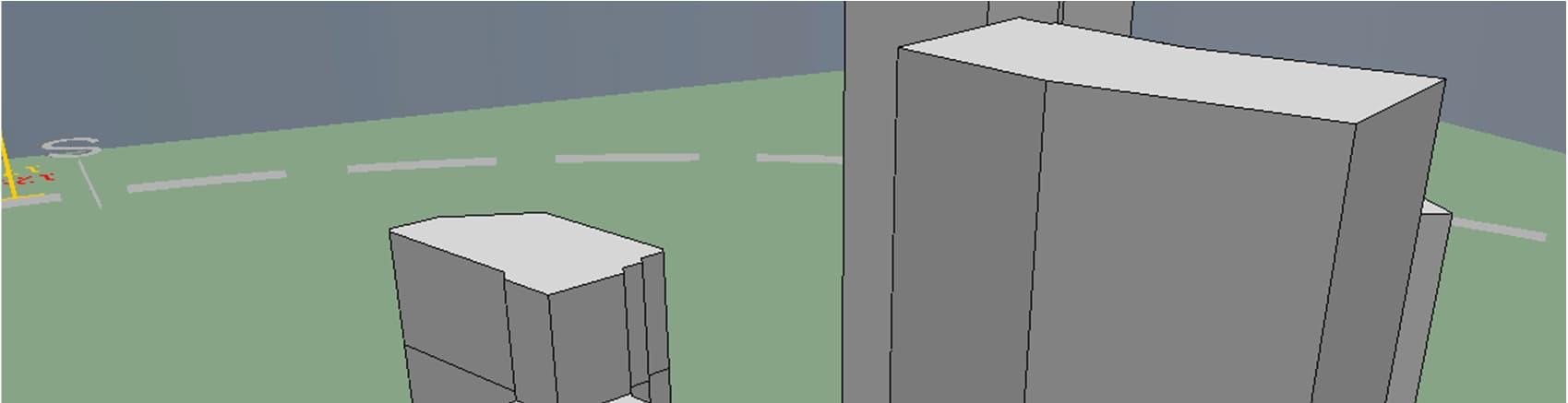


Figure 3-1 Render of the IES models and the apartment selection used in the SAP calculations of the Proposed Development N1
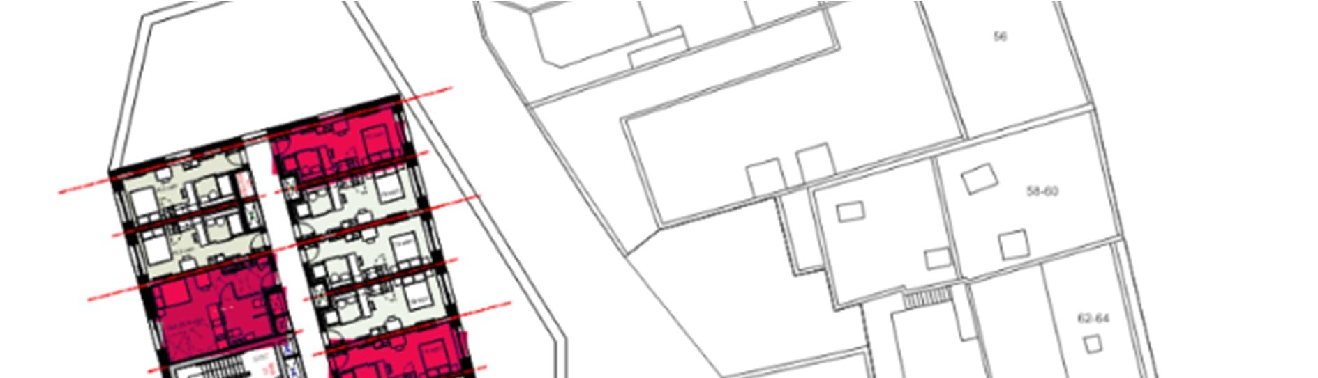
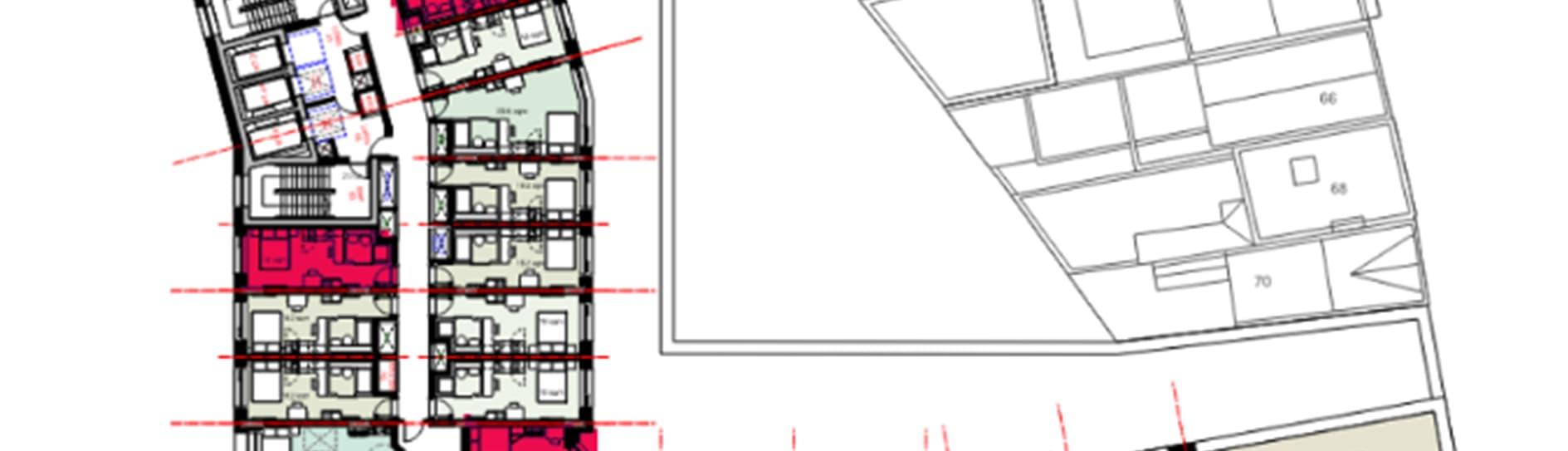
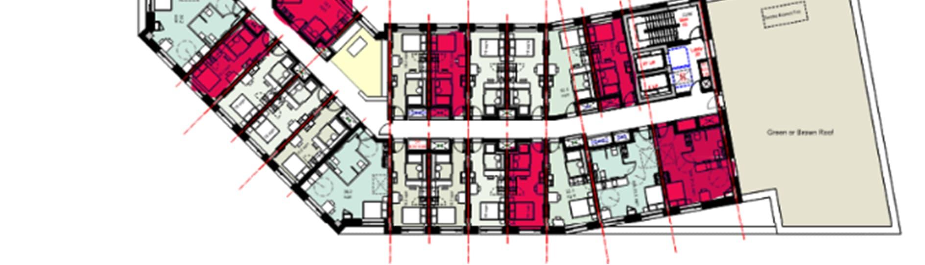
Figure 3-2 Range of apartments modelled in SAP calculation process N1. (red = selection of apartments modelled in SAP calculation)


3-3 Render of the IES models and the apartment selection used in the SAP calculations of the Proposed Development N2
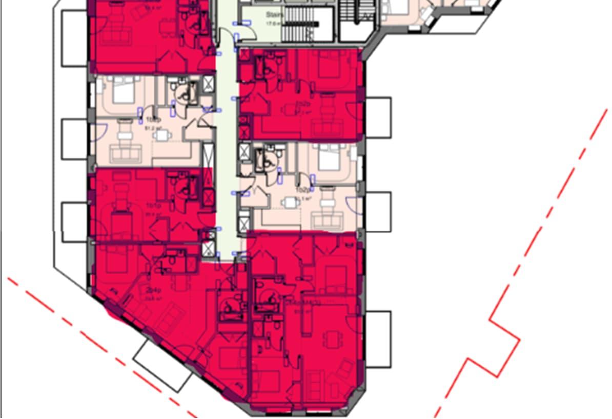
3-4 Range of apartments modelled in SAP calculation process N2 (red = selection of apartments modelled in SAP calculation)
Table 3-1 summarise the baseline carbon emissions split by type and for the residential floors of the detailed element of the Proposed Development. Part L 2021 have been used as a basis for all calculations using the GLA Carbon Emission Reporting Spreadsheet version 2.0.
Table 3-1 Baseline regulated and unregulated carbon emissions of the scheme – Residential
Table 3-2 Baseline regulated and unregulated carbon emissions of the scheme – Non-Residential
Table 3-3 Baseline regulated and unregulated carbon emissions of the scheme – Phase 1A
(TONNES CO2)
Table 3-4 Baseline regulated and unregulated carbon emissions of the scheme – The Outline Scheme
The first step to achieving Building Regulations compliance and the targets outlined previously is to reduce energy demand. The measures associated with reducing demand can be termed as ‘Energy Efficiency Measures’.
During design development, significant consideration has been given to how the building fabric will respond to its environment in order that the energy consumption of the building is reduced as far as possible through passive means. The architectural geometry, glazing area and shading elements provided in the façade are designed to maximise the passive measures, to mitigate overheating issues and maximise daylight and sunlight access within the proposed residential units.
The building fabric is optimised to reduce heat loss in winter months and minimise heat gains in summer months with the aim of maximising the passive performance. An assessment of the building façade for each Building within the detailed area (plot N1 and N2) has been undertaken to establish the effect of differing U-values and g-values on carbon emissions and Target Fabric Energy Efficiency (TFEE) values.
An average Wall U-value of 0.15 W/m2k and a Window U-value of 1.2 W/m2k is currently targeted to provide compliance with the TFEE and minimum requirements for residential developments at Be Lean stage. A thermal bridging analysis was undertaken using SAP 2021 software calculating the length of all junctions in line with the conventions fabric systems set out in the current SAP conventions v10.2. Detailed façade design and thermal bridging calculations will be performed during detailed design stage once junction details have been specified. These will inform final U-values required for each building fabric element. The final strategy for compliance with TFEE will be defined as design develops.
It is assumed in this analysis that party wall conditions are subject between the walls separating residential units only. The party walls are assumed to be fully filled with sealed edges to achieve the U-value listed in Table 4-1. The walls between communal corridors/core areas and residential units are treated as heat loss walls and the build-ups will be required to meet the U-values in Table 4-1.
The building fabric will be designed to exceed the limiting fabric requirements of Part L1 (2021) and Part L2 (2021) of the Building Regulations as applicable.
There are 4 No. multi-function air source heat pump units located on the external roof level of N1 which provides heating and cooling to the building.
The heat pumps have been designed to use low GWP refrigerant R290, and operate efficiently. When providing cooling heat can be recovered to simultaneously supply heat to the building.
There are 3 No. CO2 Air Source Heat Pumps located on the external roof level of N1 which provides domestic hot water to the building.
The primary heating/cooling plant regulates an LTHW/CHW network. The LTHW and CHW serves fan coils in each residential apartment to provide space conditioning.
Each residential unit will be provided with a Mechanical Ventilation Heat Recovery (MVHR) unit. This will be located and ducted at ceiling level.
Terminal units are designed to achieve a specific fan power in operation significantly lower than the Part L 2021 limiting SFP.
All spaces will include 100% low energy lighting.
Available roof space will be maximised for the use of PV panels.
There are 2 No. Air Source Heat Pump Units located on the external roof level of N2 which provides heating and hot water to the building.
The heat pumps have been designed to use low GWP refrigerant R290, and operate efficiently supplying heat at 60 degrees.
The primary heating/cooling plant regulates an LTHW network serving HIUs in each residential apartment to provide space heating and hot water.
Each residential unit will be provided with a Mechanical Ventilation Heat Recovery (MVHR) unit. This will be located in a utility cupboard and ducted to the façade at ceiling level.
A small number of apartments require cooling due to acoustic constraints, in this case, cooling will be supplied by an active cooling coil within the MVHR unit. All apartments have been future proofed by allowing space in utility cupboards for cooling if required in the future.
Terminal units are designed to achieve a specific fan power in operation significantly lower than the Part L 2021 limiting SFP.
All spaces will include 100% low energy lighting.
Available roof space will be maximised for the use of PV panels.
The remaining phases will also be served via ASHPs located on their respective roof levels.
The primary heating plant regulates an LTHW network. The LTHW serves in-apartment HIUs which in turn provide heating and hot water.
The Proposed Development will be fully electric.
Terminal units are designed to achieve a specific fan power in operation significantly lower than the Part L 2021 limiting SFP.
All spaces will include 100% low energy lighting.
Commercial and amenity spaces will be completed to shell and core standard only, providing base services for future extension by tenants. The tenants will be responsible for provision of services to suit their particular requirements.
Subject to future legal and technical agreements, the development will be designed for future connection of each building into a district heating network through the provision of capped connections and future plant space should a connection prove to be feasible.
PV arrays are proposed on the roof of the proposed buildings to contribute towards the on-site carbon reduction target of 35% and the overall Zero Carbon Target. However, the size of the arrays will be limited due to space constraints from other plant located on the roof.
The HVAC specification as modelled in the Part L analysis is outlined in Table 4-2
Table 4-2 HVAC Specification Domestic HVAC System
Table 4-3 HVAC Specification Non-domestic HVAC System
Ductwork and AHU Leakage Has the ductwork been leakage tested?
Does the AHU meet CEN leakage standards?
Does the system have provision for metering?
Does the metering warn 'out of range' values?
CARBON EMISSION REDUCTION
Based upon the energy efficiency measures outlined and excluding the contribution of the ASHP system and PV panels, the following total carbon emissions are calculated in Table 4-4. The SAP 10.2 carbon factors have been used for all further calculations using version 2.0 of the GLA Carbon Emission Reporting Spreadsheet.
The carbon emissions from the detailed area (Plots N1 and N2) are shown to be lower than the minimum requirements of the Building Regulations by energy efficiency measures alone. This is achieved via the use of the energy efficiency measures proposed (including a highly efficient building fabric, 100% low energy lighting and mechanical ventilation with heat recovery systems) which exceed the minimum requirements of the Regulations.
Table 4-4 Be Lean: Carbon emissions after the application of energy efficiency measures – Residential BLOCK REGULATED EMISSIONS
Table 4-7 Be Lean: Carbon emissions after the application of energy efficiency measures – The Outline Scheme
*The energy efficiency savings have been calculated on the basis that the buildings are served by a central heating system served by gas fired boilers
Table 4-5 Be Lean: Carbon emissions after the application of energy efficiency measures – Non Residential
Elmhurst Design SAP 10 software was used to determine the Fabric Energy Efficiency (FEE) standards for all residential units within plots N1 and N2 (detailed application area). An analysis has been undertaken on the all the new build residential buildings within the detailed area to establish the performance of the fabric in relation to the TFEE. Results for TFEE and the Dwelling FEE (DFEE) for the detailed application buildings are as follows:
Table 4-8 Fabric energy efficiency and carbon emissions result
The approach to the façade design to the buildings in the outline element is intended to follow closely the principals established for the detailed element, as such, all residential areas across the scheme, both in the detailed and outline application areas achieve compliance with the TFEE standard. Detailed façade design and thermal bridging calculations will be performed during detailed design stage once junction details will be specified. The final strategy for compliance with TFEE will be defined as design develops. The project will ensure compliance with the TFEE is achieved.
After consumption has been reduced through the application of energy efficiency measures, the next step is to consider low carbon technologies in order to provide further reduction in carbon dioxide emissions.
An appraisal of ‘efficient supply’ technologies was undertaken through the use of district heating networks.
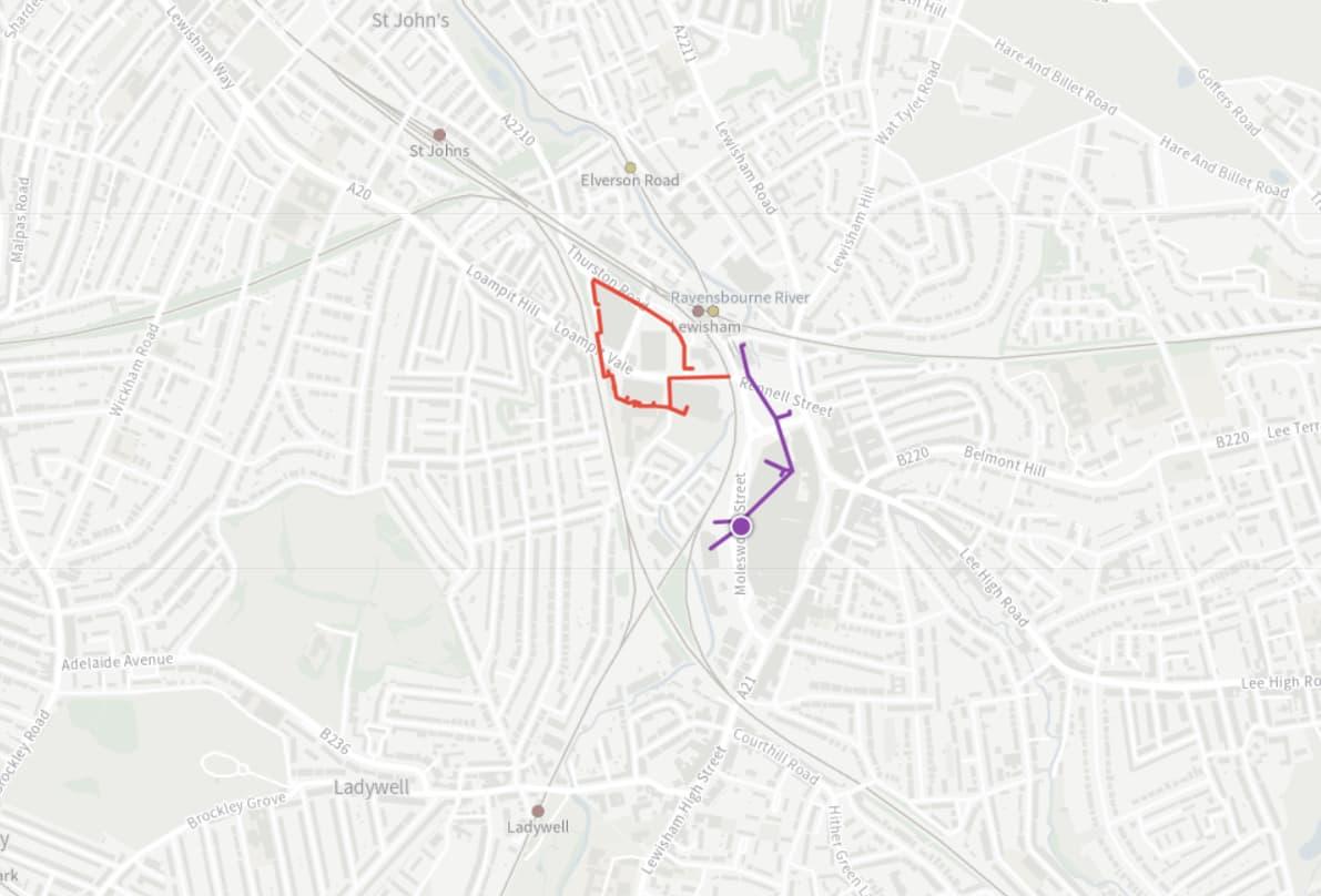
Figure 5-1 Except from the London Heat Map showing any existing (red) and proposed (purple) district heating networks, site shown in blue
The Proposed Development is located within the Heat Network Priority Areas (HNPAs). Figure 5-1 shows the location of any existing and proposed district heating systems within the vicinity of the Proposed Development. Lewisham Council is undertaking a piece of work to review the feasibility of an area wide heat network which considers connection to the Lewisham Shopping Centre Site. Due to the programme and uncertainty in the delivery of an area wide DHN by Lewisham Council, the strategy for the Lewisham Shopping Centre is being progressed such that it can be delivered without reliance on an external DHN for phase 1 and possibly later phases. The energy strategy for the Lewisham Shopping Centre development will, in accordance with GLA policy, include for future connection to a DHN. If the network does achieve heat on in time the strong preference is to connect to the network and avoid the abortive costs of building independent systems. The applicant has engaged with and collaborated with The London Borough Of Lewisham, Sustainable Energy and E.ON throughout various stages of the design, including a number of pre-application meetings focusing on this topic.
Connection to the existing Loampit Vale DHN, managed by E.ON has been explored. Currently, there is no available heat capacity on the network, and heat is high carbon being provided by CHP and gas boilers. Correspondence is ongoing with E.ON and other stakeholders to assess the viability of Loampit Vale DHN to supply low carbon heat to Lewisham Town Centre Heat Network.
Currently, it is not viable that the Proposed Development is supplied directly by an existing district heating network. It is also not viable the proposed heat networks will be operational in time for this development, particularly the detailed application area, plots N1 and N2. Therefore, in accordance with London Plan policies (and namely Policy SI3 and the heating hierarchy), a feasibility analysis has been carried out into how space and domestic hot water heating in the Proposed Development could be supplied by a communal heating system and consolidated to a single point of connection to a future heat network. The study looked at 4 possible heat network typologies listed by Table 5-1.
Table
Scenario Description
1 - Building Level Heat Network All blocks Served via rooftop heat pumps via building level heat network.
Development served by rooftop heat pumps for each phase via 3 separate heat networks.
2 – Phase Level Heat Network
3 - Site Wide Heat Network (on-site energy centre)
4 - Site Wide Heat Network (off-site energy centre)
Phase 1: N1, N2, N3
Phase 2: S1, S2, S3, S4, MV
Phase 3: C1, C2, W3, C4, C5
Dedicated energy centre for all blocks with site wide communal heat network and on-site energy centre
Dedicated energy centre for all blocks with site wide communal heat network and off-site energy centre
Centralisation of LTHW generation; rooftop used to house ASHPs is in bold*
The key factors considered in scaling of energy centralisation are as follows:
Diversification of loads will change in response to centralisation of LTHW distribution.
Installed capacity will change based on diversity.
Increased losses associated with increased distribution pipework.
Space allocation for ASHPs throughout the options.
Embodied carbon associated with each of the options for installed capacity and distribution pipework.
Each of the four scenarios have been modelled using CP1 guidance to define diversities (detailed in Appendix B). The CP1 calculation considers diversity in the DHW loads and space heating loads, with a greater number of units served resulting in a greater diversity. As a result, Scenario 3 and 4 see a much lower requirement for installed capacity, when compared to Scenario 1. A lower installed capacity means a reduced number of ASHPs required, lowering the embodied carbon associated with heat generation plant. However, centralising the ASHPs increases the distribution pipework needed and in turn increases the system heat losses.
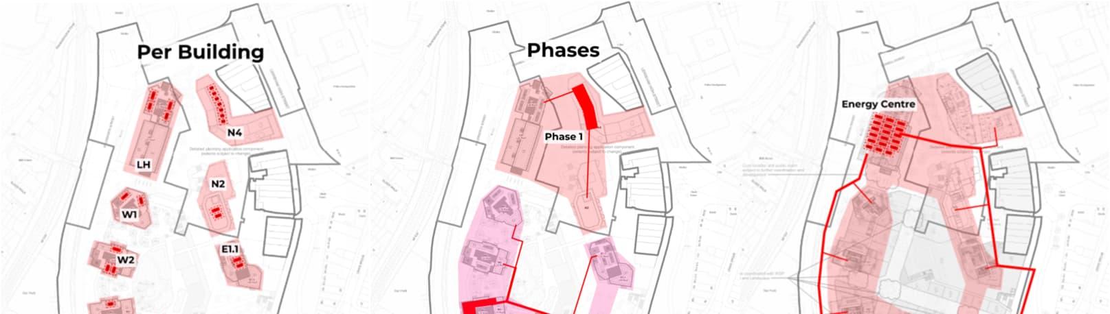
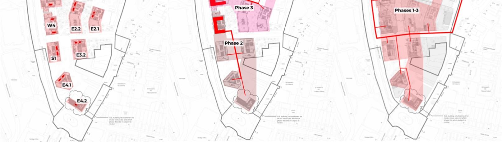
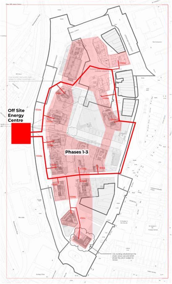
5-2 Heat generation plant and network layout for the proposed scenarios.
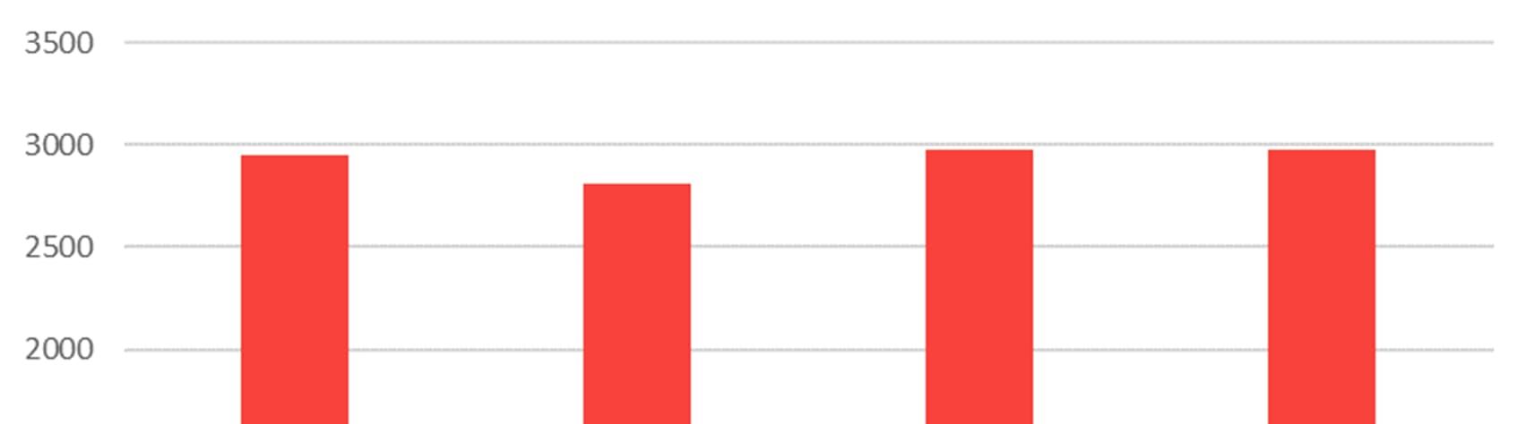
The results of the calculations for installed capacity and embodied carbon associated with each scenario is presented in Table 5-2. Up-front carbon refers to the carbon associated with the raw materials for plant and distribution pipework, transport to site and construction. In-use carbon specifically refers to the additional energy losses from having an expanded pipework distribution, with Scenario 1 as a baseline. Figure 1 gives a comparison of the scenarios in terms of whole-life carbon, and shows that from a whole-life carbon perspective Scenario 1 and 3 perform similarly, with scenario 1 leading to marginally lower emissions when compared with Scenario 3, once the additional carbon associated with the energy centre structureand operational energy losses are taken into account.From purely a carbon perspectivescenario 2 performs the best. However there are numerous practical considerations as to why this is not feasible on the site. These considerations can be broken down into a few categories as follows: Spatial Constraints, Whole Life Carbon, Microclimate Impact and Heat Recovery.
Table 5-2 Summary of scenarios considered for LTHW distribution
The scheme has been initially designed to accommodate ASHPs sized on a block-per-block basis. Moving towards a centralising these by phase introduces significant problems in accommodating the required installed capacity, even when utilising the entire roof space for mechanical plant and would likely require an additional floor to accommodate the larger centralised heat generation equipment.
The centralised energy centre would mitigate the issue of limited roof space by consolidating equipment. However, it would likely necessitate omitting one residential block from the development to house the facility, significantly impacting viability, and the deliverability of the scheme.
With increasing diversity, we see decreasing requirement for installed capacity. This saves on embodied carbon for the ASHPs, although also sees a smaller increase in embodied carbon for distribution pipework and operational losses in the increased pipework. While the sitewide, centralised option would make the greatest saving in whole life carbon, the figure used in Table 2 additionally accounts for the embodied carbon of 300 tCO2e for the energy centre based on 150 kgCO2e/m2, for a 2-storey energy centre building with a footprint of 1000 m2. This has been added, since unlike the other options which utilise roof space, it will require a dedicated structure to house the ASHPs.
A large centralised ASHP energy centre can induce a microclimate by expelling concentrated cold air during the heating process, which can lower the ambient temperature in its immediate vicinity (also known as a cold plume). This localised cooling effect can influence outdoor conditions around the centre, significantly reducing the outdoor thermal comfort and usability of outdoor space surrounding the plant enclosure. This can also impact the performance of the ASHPs, and may require extensive specialist CFD modelling of the cold plume. The concentration of ASHPs could also have a significant acoustic impact to the local area, which will need to be confirmed in a separate acoustic survey. Heat Recovery
In accordance with GLA policy, heat loads will be minimised across the site through the energy hierarchy: be lean, be clean and be green. The proposals for buildings which are located above the shopping centre (phase 3 of the development) include multi-function heat pumps providing simultaneous heating to the residential uses and cooling to
the non-residential uses. This allows waste heat from cooling heat rejection to be recovered and used within the residential parts of the development. The non-residential cooling loads are low in comparison with the residential heating demands, allowing a large amount of the cooling to be generated from waste heat from the heating system.
In summary, a site wide heat network for the Lewisham Shopping Centre development has been considered and concluded not to be feasible within the site boundary due to adverse effects on public realm (noise, microclimate and reduced development area for residential buildings e.g. one building). The comparison between decentralised (building by building) and centralised (off site energy centre as part a wider DHN scheme) shows they are equivalent in when the whole life carbon impact of the schemes have been assessed. The best option for The Proposed Development based on this analysis, and wider site constraints, is Scenario 1.
In accordance with the GLA’s Energy Assessment Guidance on preparing energy assessments, the Proposed Development’s system has been designed to facilitate connection to the proposed network should such connection become viable. Energy Statements should:
“commit to a site wide heat network to allow connection to existing or planned district heating networks identified in the area”
Table 5-3 shows the estimated annual heat demand of the Proposed Development based on benchmark information and energy modelling to date. Due to uncertainty at this stage of the design this has been presented as a range.
Table 5-3 Annual heating demand calculated for the Proposed Development
HEAT DEMAND N1 (MWH/YR)
(MWH/YR)
Detailed energy centre layouts will be developed as part of the schematic design stage post planning; however sufficient space has been allowed for all plant to be accommodated. Proposed plant spaces are subject to further optimisation as design develops.
Due to limited space the energy centres will only serve the Proposed Development and is unable to accommodate capacity to serve any neighbouring developments. Detailed MEP drawings showing the plant space provision are provided in the appendices of this document.
Previously, the GLA encouraged the use of CHP systems; however, recent GLA guidance discourages the use of CHP. As CHP is not proposed for the Proposed Development this minimises the noise levels on site. The Proposed Development will be served by ASHPs which will provide space conditioning and domestic hot water.
The ASHPs will be located at roof level of the Proposed Development and will not use additional land adjacent to the Proposed Development.
The location of the units on the roofs has been selected to minimise impact on adjacent properties. Noise levels will comply with local planning requirements.
It is anticipated that the energy centre equipment will be sized to serve only the requirements of the Proposed Development as there is not a heat network in place to facilitate the exportation of energy to other buildings in the local area.
There are no individual, or direct electric heating systems provided throughout the Proposed Development.
As the Proposed Development is not proposing to connect to a district heating network or be served by CHP, the carbon emissions savings remain unchanged from the “Be Lean” stage of the Energy Hierarchy. The overall carbon emissions for the detailed portion and outline portions of the Proposed Development is shown in Table 5-4 and TABLE REFS FOR OUTLINE. The SAP 10.2 carbon factors have been used for all further calculations using version 2023 version of the GLA Carbon Emission Reporting Spreadsheet.
Table 5-4 Be Clean: Carbon emissions after the application of energy efficiency measures – Residential BLOCK
*The energy efficiency savings have been calculated on the basis that the
Table 5-5 Be Clean: Carbon emissions after the application of energy efficiency measures – Non Residential
5-6 Be Clean: Carbon emissions after the application of energy efficiency measures – Phase 1A BLOCK
energy efficiency savings have been calculated on the basis that the buildings are served by a central heating system served by gas fired boilers only, with a seasonal efficiency of 91%
Table 5-7 Be Clean: Carbon emissions after the application of energy efficiency measures – The Outline Scheme
Renewable energy technologies can provide a source of energy on-site that is not primarily based on the consumption of fossil fuels or grid electricity and/or utilises a heat source that is renewable such as ground source and solar thermal systems.
In accordance with the requirements of the London Plan, Policy SL12, a number of renewable energy technologies have been evaluated and this section discusses how they may be applied to the Proposed Development.
Harnessing the kinetic energy of wind can provide a renewable source of onsite electricity generation. Wind turbines need to be positioned where a frequent and steady source of wind is available that is not too turbulent or uneven in direction. Typically, wind turbines are positioned on the roof of buildings that are significantly higher than their surroundings and or located in open areas where there is minimum disruption to prevailing winds.
The Proposed Development is located within an urban environment with near-by buildings providing turbulent wind conditions unsuitable for wind power generation. In addition, it is not considered appropriate in townscape, architectural and aviation safeguarding terms to provide wind turbines on top of buildings. On that basis, they are not suitable for the Proposed Development.
Biomass heating has embodied environmental impacts from transport and fuel combustion which makes it less desirable in Air Quality Management Areas (AQMAs), such as where the Site of the Proposed Development is located. A review of the potential impact on air quality from increased wood fuelled biomass use in London has been carried out by AEA Energy & Environment and was published in December 2007. The assessment indicates that potentially increasing the contribution from small-scale wood fuelled biomass combustion may lead to a substantial increase in nitrogen dioxide and particulate matter concentrations.
Further to this, solid biomass relies on a reliable fuel supply which must be delivered and stored on site. The Site therefore requires good access routes and space for fuel storage and plant, which could not feasibly be incorporated within the Proposed Development. It also has relatively high maintenance requirements and fuel costs.
This technology is therefore deemed to be unsuitable for the Proposed Development.
Ground source heating and/or cooling may be incorporated to make use of the thermal storage and ground temperature to provide heating and/or cooling to a building. Ground source heating is an effective renewable energy source when used to provide space heating via low grade heating system such as underfloor heating. However, as there is insufficient space for the heating coils or bore holes required, it is not considered feasible for the Proposed Development.
Solar thermal hot water (STHW) generation involves capturing solar radiant heat to preheat or heat domestic hot water. Correctly located and orientated, solar thermal systems can meet a proportion of a building’s domestic hot water dependent on the expected demand profile and available space for locating STHW panels. Due to the limited amount of available roof space, a STHW system is not proposed for the Proposed Development.
Air source heat pumps (ASHPs) are capable of providing heating and/or cooling utilising air temperatures. The use of ASHPs is an effective low carbon technology as they have high efficiencies for both heating and cooling.
With the decarbonising grid due to an increase in renewable energy generation, the operational impact of electrically led systems is reduced. Therefore, the benefit of heat pump technologies will improve through the lifetime of the Proposed Development. Air source heat pumps are proposed for the Proposed Development as described in the previous section.
Bodies of water can be used to extract or reject heat as long as there is an adequate water flow. WSHPs can have a higher coefficient of performance (COP) than ASHPs due to the higher temperature of the heat source which is constant throughout the year. However, due to the lack of nearby water sources, WSHPs are not proposed for the primary loop in the Proposed Development.
The feasibility of providing PV panels has been assessed based upon estimated energy production (kWh) from the installed location along with manufacturers cost data to enable a life cycle cost analysis to be undertaken. Panels correctly oriented, maintained and not obscured by shading can be expected to provide in the region of 120kWh/m2/year in London.
PV arrays are proposed on the roofs of the Proposed Development to provide a reduction in carbon emissions from renewable sources. Currently, it has been estimated that a total area of approximately 200 m2 of PV panels can be accommodated on the roof of Residential Block N2 and approximately 200 m2 of PV panels on Residential Block N1, representing 35% of total roof area. A maximum of approximately 1300 m2 of PV panels are anticipated to be able to be accommodated on the roofs of the buildings within the outline element. However, this is still under design development and is subject to change as the design progresses.
There are no known issues regarding the installation of roof mounted PVs. They will be located on the roof of the buildings therefore require no additional land and there are no acoustic issues to consider with PVs.
The Department for Energy Security and Net Zero (DESNZ) reports annually the average unit costs for electricity, the current average unit cost for domestic electricity is 31.51 p/kWh2. Using information published in 2024 on B&D Energy’s website the cost per heat from a heat network is 9.54 p/kWh3. This price is a direct cost per delivered kWh heat and excludes any service or standing charges.
To estimate the operational cost of the ambient loop system in comparison to an example DHN strategy the following demands have been calculated for the Proposed Development:
As the heating system is split into a central heat pump and individual heat pumps, the relative efficiencies of each system have been considered and an overall SCOP for both DHW and space heating (as per Table 6-1).
Applying the above demands, efficiencies and fuel unit costs the comparative annual costs are shown in Table 6-1.
Table 6-1 Comparing estimated heating and hot water costs for tenants
For a 60m2 flat, this equates to approximately £304 per year for the building heatpump system and £315 per year for the example DHN strategy. This shows that the high efficiency heatpump system able to deliver heat at lower annual cost to the customer than a heat network.
The Proposed Development will be provided with Building Management Systems (BMS) in each of the buildings. These will control and monitor the building systems and services throughout the Proposed Development, provide feedback of plant, system performance and energy usage of the system. The BMS will analyse this data to enable optimum use of the engineering facilities within the Proposed Development with minimum of human intervention, and maximum energy efficiency.
The landlord services fall under the category of sub metering as the main supplies will be bulk metered as part of the building switch rooms. Both small power and lighting are to be sub metered in distribution boards in compliance with TM39:2009. This is achieved via in line meters in the distribution boards. All metering information can be collected and distributed to the BMS via the landlords unified network.
Residential units will be provided with small metering to minimise residential unit access.
All renewable energy technologies which may be considered feasible for the Proposed Development have been assessed, the outcomes of which are summarised above. From that exercise, it was concluded that both heat pumps
and photovoltaic panels would be suitable for inclusion in the Proposed Development. Savings from
systems within plots N1 and N2 are shown in the below tables.
Table 6-2 Be Green: Carbon emissions after providing renewable energy – Residential
*The energy efficiency savings have been calculated on the basis that the buildings are
boilers only, with a
Table 6-3 Be Green: Carbon emissions after providing renewable energy – Non Residential
2 https://www.gov.uk/government/statistical-data-sets/annual-domestic-energy-price-statistics
3 https://bdenergy.org.uk/charges-2024/?doing_wp_cron=1722876046.1231141090393066406250
*The energy efficiency savings have been calculated on the basis that the buildings are served by a central heating system served by
Table 6-4 Be Green: Carbon emissions after providing renewable energy – Phase 1A
Emissions for the outline element of the application site have been estimated based on detailed site application calculations by proportioning results from Plot N1 and N2 calculations to outline GIA areas for the remainder of the masterplan.
Table 6-5 Be Green: Carbon emissions after providing renewable energy – The Outline Scheme
From the results above, it is clear that the Proposed Development site wide exceeds the GLA target of 35% reduction of emissions over Part L. While the non-residential areas alone fall short of this target, the passive and active measure have been maximised at this stage and efforts will continually be maximised as the design moved into detailed design stage.
The Proposed Development has sought to and is committed to complying with the requirements described in the ‘Be Seen’ – Energy Monitoring Guidance’ document (September 2021) for the “Planning Stage”, “As-Built Stage” and “InUse Stage”.
For compliance with “Planning Stage” requirements, the following has been completed for the Proposed Development:
Completion of the GLA’s ‘be seen’ spreadsheet with performance indicators including contextual data, building energy use and carbon emissions for the entire Proposed Development as a whole. (Note this will be downloaded from the ‘Be Seen’ webpage and completed within 4 weeks of planning approval.)
Confirm target dates for all subsequent ‘Be Seen’ stages.
Report the energy consumption (kWh/m2) and carbon emissions (tonnes CO2/m2) estimates following Part L compliant methodology using SAP assessments as per the ‘Be Seen’ guidance.
Within the Landsec - Urban Opps Net Zero Carbon Strategy targets have been proposed for operational energy. The targets have been set at three levels: Backstop, Achievable Best Practice and Pioneering. The aim of these targets is to drive the operational performance of the development and reduce carbon emissions in line with Landsec’s sciencebased targets approach and their commitment to be a net zero carbon company by 2030.
The expected aim for the development is the Achievable Best Practice target. The targets for operational energy are detailed Table 7-1 and Table 7-2:
Table 7-1 Landsec Operational Energy Targets Residential
USE INTENSITY
Backstop
Achievable Best Practice
Pioneering
<50kWh/m2 per GIA
<45kWh/m2 per GIA
<40kWh/m2 per GIA
Table 7-2 Landsec Operational Energy Targets Student/Co-Living
<30kWh/m2 per GIA
<20kWh/m2 per GIA
2 per GIA
To assess the development against these targets, the PassivHaus Planning Package (PHPP) tool has been utilised. The model has been developed based on Stage 2 information on both the N1 and N2 developments provided by Mae and Archio. The Phase 2 were input into PHPP to understand the operational energy performance of the two blocks.
Each block within the detailed application area (plots N1 and N2) was independently assessed within PHPP with 445 units in N1 and 119 units in N2. The interior winter temperature was set at 20oC as is standard in PHPP. The standard utilisation pattern and occupancy rates for dwellings was used for the internal heat gains, apart from N1 apartments which were assumed to have an occupancy of 1.1 people per apartment (assuming that 10% of apartments would be inhabited by a couple).
A typical residential floor of both buildings was selected and developed for inclusion in the PHPP modelling. This was selected as L04-08 for N1 and L03 for N2. The non-domestic and communal areas of both buildings have not been modelled as the PHPP tool is primarily a residential energy assessment tool.
The climate data selected was Zone 02 - Thames Valley which provides an increase heating load compared to that of Zone 01 - London.
The fabric specifications as per the SAP assessments were utilised for this assessment for consistency.
For the glazing elements, PHPP has an additional factor in “installation thermal bridging”. Due to lack of information on this, this was selected as per the worst examples provided within the spreadsheet. The window U-values, pre installation factor, were calculated to match the information provided by EOC in their preliminary U-value assessment.
The MVHR unit has been selected as per the SAP calculations.
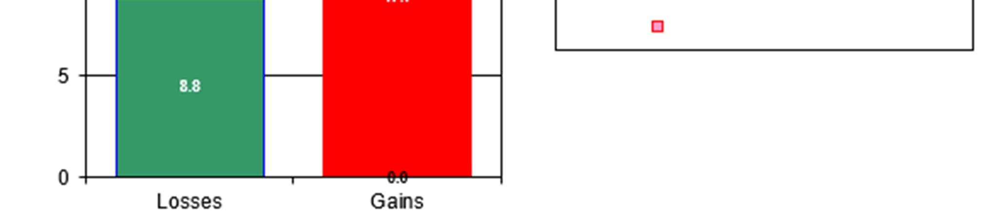
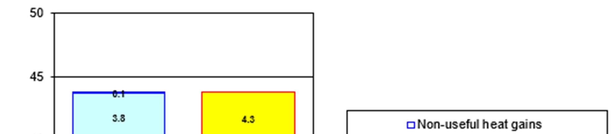
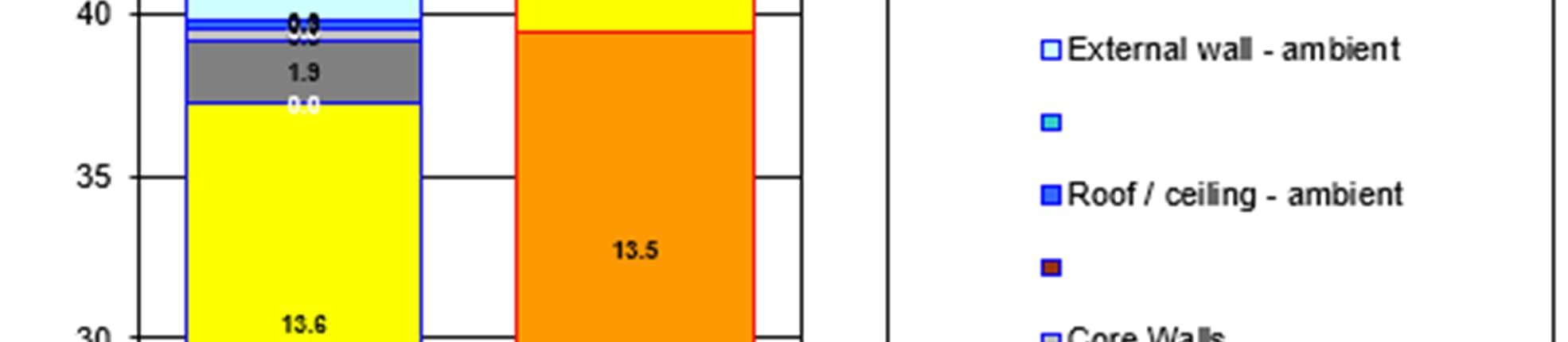
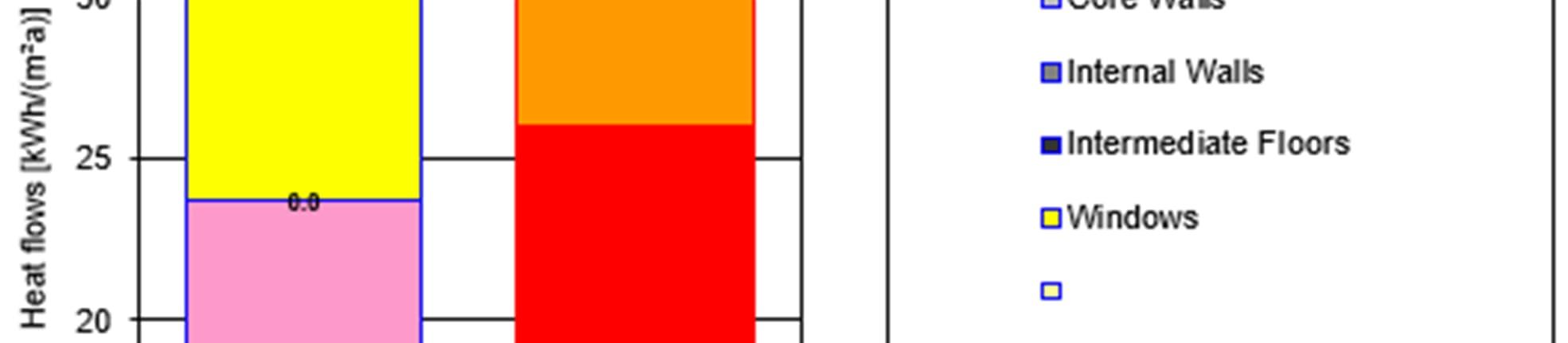
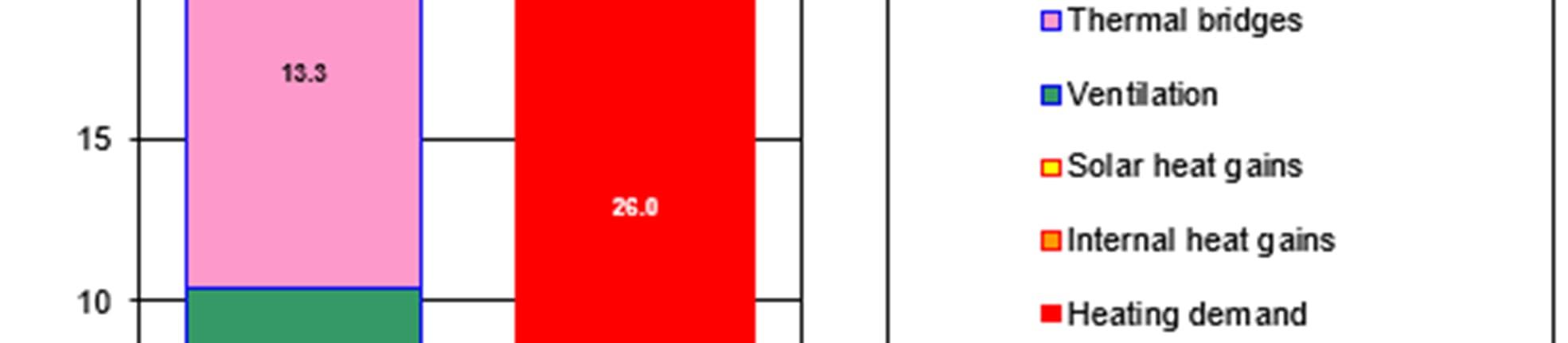
From the PHPP tool, the below energy balance of heating has been extracted for both N1 and N2. Both outputs indicated significant losses through ventilation but with the primary losses being through the glazing.
Backstop <100kWh/m2 per GIA <30kWh/m2 per GIA
Achievable Best Practice
Pioneering
<85kWh/m2 per GIA
<60kWh/m2 per GIA
<20kWh/m2 per GIA
<15kWh/m2 per GIA
All the inputs and design specifications will be reviewed in more detail at later design stages.

At this stage of the design, some high level assumptions have been made. For example, the total length of distribution pipework and ductwork within the flats is not yet known so an approximate rule of thumb has been used. The inputs into the PHPP models will be fine tuned at later design stages where more information is readily available.
Overall the performance of blocks N1 and N2 within PHPP are outlined in the table below.
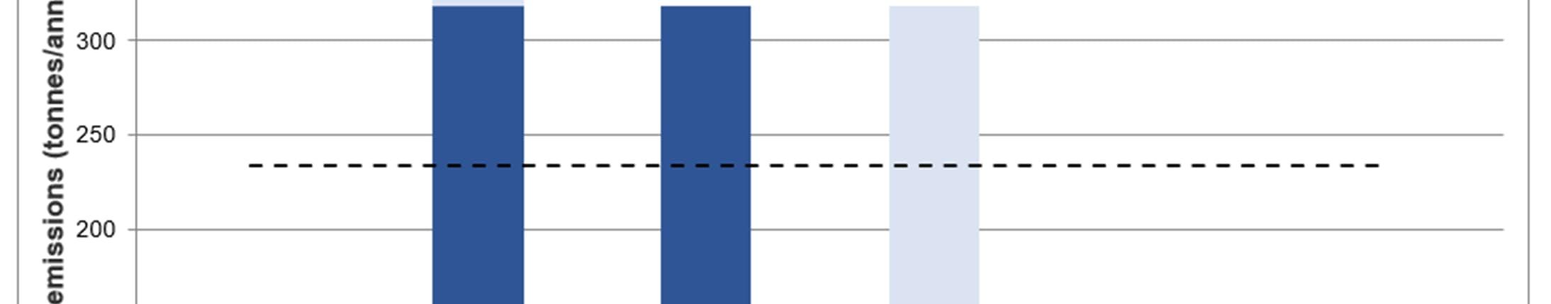
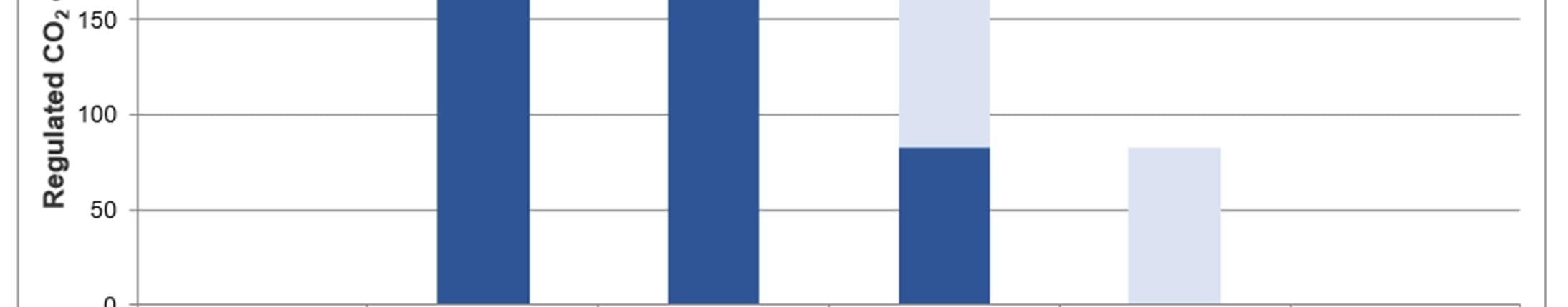
The three principal steps taken: Be Lean (Use Less Energy), Be Clean (Supply Energy Efficiently) and finally Be Green (Renewable Technology Measures) are summarised below. The target regulated (Building Regulations compliant) carbon emissions for the Proposed Development are calculated to be 359.4 tonnes CO2 per annum. Any percentages refer to the reduction of carbon emissions from this baseline.
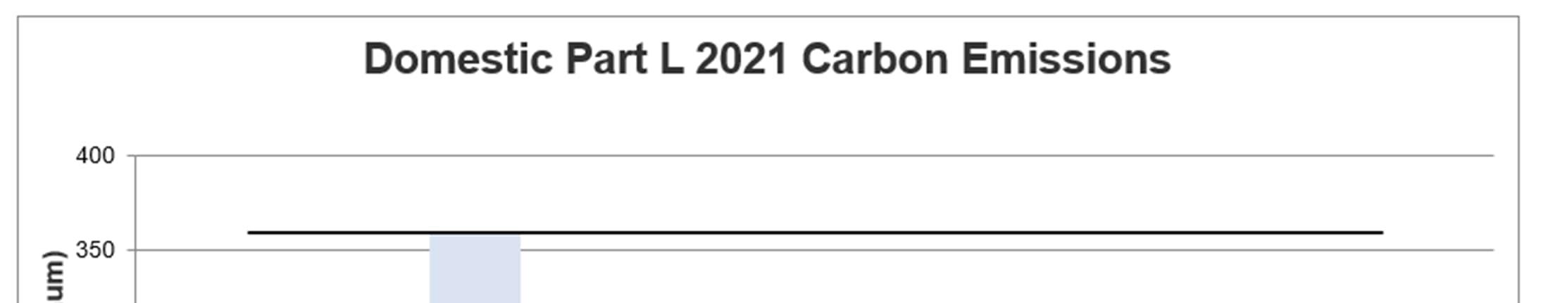
The application of the measures identified in Section 0 provides an overall reduction of 10% in carbon emissions from the detailed elements of the Proposed Development and a total carbon reduction of 36.9 tonnes CO2 per annum from the baseline carbon emissions. After this stage of the energy hierarchy the total regulated carbon emissions from the detailed element of the Proposed Development is shown to be 322.5 tonnes CO2 per annum.
When extrapolated across the outline scheme this led to a further 206.8 tonnes CO2 per annum from the baseline carbon emissions compliant development. After this stage of the energy hierarchy the total regulated carbon emissions from the outline element of the Proposed Development is shown to be 2,270.6 tonnes CO2 per annum.
A connection to a district heating network is not currently possible with no current District Heat Networks in the area. Although a network is being planned, it is not expected to be ready for connection to the Site in time for first occupation of the Site. Provision will be made to allow for future connection to a district heating network.
The feasibility of a range of renewable technologies has been assessed in the context of the London Plan. It was concluded that both photovoltaic panels and air-source heat pumps are suitable for inclusion in the proposals.
The renewable technologies provide together an overall reduction of 65% in carbon emissions from the detailed element of the Proposed Development and a total carbon reduction of 235.1 tonnes CO2 per annum from the baseline carbon emissions compliant development. After this stage of the energy hierarchy the total regulated carbon emissions from the detailed element of the Proposed Development is shown to be 87.4 tonnes CO2 per annum.
When extrapolated across the outline scheme this led to a further 1,365.5 tonnes CO2 per annum from the baseline carbon emissions compliant development. After this stage of the energy hierarchy the total regulated carbon emissions from the outline element of the Proposed Development is shown to be 905.1 tonnes CO2 per annum.
In direct response to the information outlined within the Greater London Authority (GLA) Energy Assessment Guidance on Preparing Energy Assessments (June 2022), the results outlined previously are summarised in the tables below, with the results presented against the overall carbon reduction target. As per the guidance, these have been separated into summaries for new build Residential and Non-Residential.
The proposals for the Proposed Development outlined within this energy strategy are considered to maximise the potential carbon savings which can be achieved on the Site through the provision of:
A highly efficient building fabric.
Efficient building services plant, including providing high efficiency air handling plant with heat recovery and low specific fan power.
100% low energy lighting and maximised use of LED and low energy fixtures.
Waste water heat recovery.
Highly efficient natural refrigerant air-source heatpumps with heat-recovery.
Roof mounted PV panels
Overall, the detailed element of the Proposed Development is shown to exceed the carbon reduction target of 35% set by GLA. The building fabric, air tightness, thermal bridging and g-value specifications have all been optimised to provide the maximum carbon reductions. High performing efficient building services plant, including providing high efficiency air handling plant with heat recovery and low specific fan power have been considered.
The carbon emissions of the proposed non-residential portion of the detailed element are expected to be refined once more detailed internal layouts are incorporated into the Part L analysis. This will impact the MEP services strategy along with specified efficiencies and associated controls.
Elmhurst Design SAP 10 software was used to determine the Fabric Energy Efficiency (FEE) standards for all residential units within plots N1 and N2 (detailed application area). An analysis has been undertaken on the all the new build residential buildings within the detailed area to establish the performance of the fabric in relation to the TFEE. Results for TFEE and the Dwelling FEE (DFEE) for the detailed application buildings are as follows:
Table 8-1 Fabric energy efficiency and carbon emissions result for Residential Blocks N1 & N2
The approach to the façade design to the buildings in the outline element is intended to follow closely the principals established for the detailed element, as such, all residential areas across the scheme, both in the detailed and outline application areas achieve compliance with the TFEE standard. Detailed façade design and thermal bridging calculations will be performed during detailed design stage once junction details will be specified. The final strategy for compliance with TFEE will be defined as design develops. The project will ensure compliance with the TFEE is achieved.Part L 2021 Carbon Dioxide Emissions
The following tables provide a summary of the performance of the detailed element of the Proposed Development. The performance of residential and non-residential elements is provided separately in Table 8-2 summarises the performance of the detailed element of the Proposed Development.
Table 8-2 Regulated carbon dioxide savings from each stage of the energy hierarchy (SAP10.2 carbon factors)
Emissions for the outline element of the application site have been estimated based on detailed site application calculations by proportioning results from Plot N1 and N2 calculations to outline GIA areas for the remainder of the masterplan.
CARBON DIOXIDE EMISSIONS
Under Policy SI2: Minimising Greenhouse Gas Emissions, where it is clearly demonstrated that the zero-carbon target cannot be fully achieved on-site, any shortfall should be provided, in agreement with the borough, either: 1) through a cash in lieu contribution to the borough’s carbon offset fund The cash-in-lieu contribution shown in
Table 8-3 is based on a price of £95/tonne for a period of 30 years according to the GLA Energy Assessment Guidance. This has been calculated based on the currently calculated carbon emissions after the application of the GLA energy hierarchy.
Table 8-3 Phase 1A - Carbon Offset PERFORMANCE INDICATOR
Total Site cash-in-lieu contribution
Table 8-4 The Outline Scheme - Carbon Offset PERFORMANCE INDICATOR
In line with Policy SI 2 (Minimising greenhouse gas emissions) and SI 3 (Energy infrastructure) of the London Plan, the possibility for including measures for reducing peak energy loadings has been considered in detail.
Load and peak demand calculations have been undertaken for the whole Proposed Development and appropriate system capacity has been provided.
Heating is supplied by air source heat pumps at roof level, heat demand has been calculated for both the detailed submission and the wider masterplan, as shown in Table 9-1.
Table 9-1 Heating Load
The peak cooling load has been estimated as 300 KW for N1, see Table 9-2. Cooling is supplied from the 4-pipe heatpumps at roof level, and therefore available cooling capacity should be far greater than the estimated demand. Arrangement of roof level HVAC plant will be optimised
Table 9-2 N1 Cooling Load
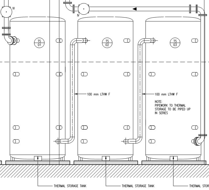
Figure 9-1 Thermal Storage schematic
The detailed load analysis assessing the demand flexibility which will reduce the maximum demand will be calculated at the next stage.
The same approach will also be applied to the outline element of the Proposed Development.
2.5 m3 of thermal storage shall be provided in for both N1 and N2 building. Thermal stores shall be utilised to provide system resilience and downtime of ASHPs. This equates to a maximum heat capacity of 100 kWh. Thermal stores have been sized to meet the 200 kW for 30 minutes which allows the heat pumps to run at a more efficient constant level.
WSP has undertaken an electrical load demand analysis for the detailed element of the Proposed Development as summarised in Table 9-3.
Table 9-3 Electrical Load Analysis
The electrical supply to the development will be at 11kV derived from the local utility (UKPN) network. It is anticipated the 11kV supply will be delivered to site as a ‘bulk’ supply to serve the entire development. The bulk supply will be either an 11kV ‘loop’ supply or a pair of units protected (Solkor) cables, either way it will be two 11kV cables.
The transformer configuration arrangement across Phase 1Phase 1a of Lewisham Shopping Centre (LSC) development is considered to be as follows:
Substation (SSTN1) 1000kVA: To supply Retail units and Residential services. Located within Block N2 at Level 00.
Substation (SSTN2) 1000kVA: To supply Landlords services. Located within Block N2 at Level 00.
Substation (SSTN3) 1000kVA: To supply Retail units and Residential services. Located within Block N1 at Level 00.
Substation (SSTN4) 1000kVA: To supply Landlord services. Located within Block N1 at Level 00.
Block N1 will also accommodate two existing relocated network substations. A DNO HV intake room has been allowed for in North Building at Basement 1 Level. Ring Main Units (RMU’s) shall be installed in order to allow for HV ring distribution to substations located at basement level.
Battery storage has not been included.
Potential measure for reducing the peak demands will be investigated at detailed design stage. This is due to the early stage of the design and several factors being as yet undetermined.
Table 9-4 Summary of interventions for achieving flexibility FLEXIBILITY ACHIEVED THROUGH
Electrical Energy Storage (kWh) capacity No Battery storage has not been included due to a lack of renewable energy generation and space considerations
Heat Energy Storage (kWh) capacity Yes 15 m3 and 20 m3 thermal storages have been included in North and South Building to help reduce peak heat demand. This equates to a maximum heat capacity of 1400 kWh
Renewable Energy Generation (load matching) Yes The design has maximised the use of roof space for PV
Gateway to enable automated demand response No
Smart systems integration No
Not proposed
Not proposed
Table 9-5 Summary of site-wide peak demand, capacity and flexibility potential
Estimate Peak Demand (MW)
by DNO at next stage
Available Capacity (MW) TBC by DNO at next stage TBC
Flexibility Potential (MW) TBC by DNO at next stage TBC
Revised Peak Demand (MW) TBC by DNO at next stage TBC
Percentage flexibility predicted (%) TBC by DNO at next stage TBC
Policy SI 4 (Managing heat risk) ofthe London Plan require major development proposals to reduce potential overheating and reliance on air conditioning systems and demonstrate this is in accordance with the following cooling hierarchy.
1. Reduce the amount of heat entering a building through orientation, shading, albedo, fenestration, insulation and green roofs and walls
2. minimise internal heat generation through energy efficient design
3. Manage the heat within the building through exposed internal thermal mass and high ceilings
4. Provide passive ventilation
5. Provide mechanical ventilation
6. Provide active cooling systems (ensuring they are the lowest carbon options).
Dynamic thermal models were built in IES VE to verify the internal conditions of the residential and non-residential elements of the Proposed Development. All occupied spaces have been analysed against the criteria within TM52 and TM59 (these criteria are expanded on below). A stepped approach was utilised following the cooling hierarchy. Measures were incorporated into the models and building design until internal conditions became acceptable.
The following weather files have been used in the analysis following the GLA guidance for overheating assessments found in the Energy Assessment Guidance:
London_LHR_DSY1_2020High50 (a moderately warm summer)
London_ LHR _DSY2_2020High50 (a year with a very intense single warm spell)
London_ LHR _DSY3_2020High50 (a year with a prolonged period of sustained warmth)
Domestic overheating can cause significant discomfort and stress to occupants, often resulting in costly mitigation measures for owners/developers. As a result, building physicists and engineers worked with CIBSE to develop a domestic overheating risk assessment methodology, TM59 and the latest ‘Approved Document Part O’.
APPROVED DOCUMENT PART O:
Requirement O1 Overheating Mitigation of the Building Regulations states that dwellings, or other buildings containing rooms for residential purposes, should make reasonable provision to:
Limit unwanted solar gains in summer
Provide an adequate means to remove heat from the indoor environment
Part O requires the use of CIBSE TM59 which sets the following two criteria:
For living rooms, kitchens and bedrooms, the number of hours during which the temperature difference is greater than or equal to one degree during the period May to September inclusive shall not be more than 3% of occupied hours.
For bedrooms, to guarantee comfort during the sleeping hours the operative temperature in the bedroom from 10 pm to 7 am shall not exceed 26oC for more than 1% of annual hours.
Table 10-1 Limits on CIBSE’s TM59 modelling in Approved document part O
Approved Document Part O
a. When a room is occupied during the day (8am to 11pm), openings should be modelled to do all of the following
b. At night (11pm to 8am), openings should be modelled as fully open if both of the following apply
c. When a ground floor or easily accessible room is unoccupied, both of the following apply.
d. An entrance door
Start to open when the internal temperature exceeds 22°C.
Be fully open when the internal temperature exceeds 26°C.
Start to close when the internal temperature falls below 26°C.
Be fully closed when the internal temperature falls below 22°C.
The opening is on the first floor or above and not easily accessible.
ii. The internal temperature exceeds 23°C at 11pm.
In the day, windows, patio doors and balcony doors should be modelled as open, if this can be done securely
ii. At night, windows, patio doors and balcony doors should be modelled as closed.
should be included, which should be shut all the time.
CIBSE TM52 sets out criteria based on an adaptive approach to thermal comfort. The ‘adaptive’ approach to thermal comfort shows that the temperatureat whichthe majority of people are comfortable ‘tracks’ the mean indoor temperature because of the correlation between indoor and outdoor temperature in naturally ventilated (free-running) buildings.
The following three criteria, taken together, provide a robust yet balanced assessment of the risk of overheating of buildings in the UK and Europe. A room or building that fails any two of the three criteria is classed as overheating.
The first criterion states the number of hours (He) during which ∆T (the difference between the actual operative temperature in a room and the limiting maximum acceptable air temperature) is greater than or equal to one degree (K) during the period May to September inclusive shall not be more than 3% of occupied hours.
The second criterion deals with the severity of overheating within any one day, which can be as important as its frequency, the level of which is a function of both temperature rise and its duration. This criterion sets a daily limit for acceptability. To allow for the severity of overheating the weighted exceedance (We) shall be less than or equal to 6.
The third criterion sets an absolute maximum daily temperature for a room, beyond which the level of overheating is unacceptable. The value of ∆T shall not exceed 4K.
There are four assessment categories within TM52 which is dependent on the acceptable temperature range of freerunning buildings. The CIBSE suggestion is that designers should aim to remain within the Category II limits.
Table 10-2 Categories of building types within CIBSE TM52
Category Explanation Suggested acceptable range (K)
High level of expectation only used for spaces occupied by very sensitive and fragile persons
expectation (for all new buildings and renovations)
III A moderate expectation (used for existing buildings) ± 4
IV Values outside the criteria for the above categories (only acceptable for a limited period) > 4
The GLA acknowledges that meeting the TM52 criteria is challenging for DSY2 & DSY3 weather files but expects the criteria is met for the DSY1 weather scenario.
For the purposes of this analysis the following key assumptions have been made based on CIBSE TM59 guidance:
Occupancy and equipment gains
Maximum sensible heat gain of 75W/person and a maximum latent heat gain of 55W/person are assumed in living spaces.
Lighting energy is assumed at 2W/m2 from 6pm to 11pm.
Gain profiles are as described on the table below:
Table 10-3 Occupancy and equipment load assumptions
UNIT/ROOM TYPE OCCUPANCY EQUIPMENT LOAD
Studio 2 people at all times Peak load of 450W from 6pm to 8pm 200W from 8pm to 10pm 110W from 9am to 6pm and from 10pm to 12pm
1 bedroom apartment
Kitchen/Living/Dining
2 bedroom apartment
Kitchen/Living/Dining
3 bedroom apartment
Kitchen/Living/Dining
Double bedroom
Base load of 85W for the rest of the day
1 person from 9am to 10pm; room is unoccupied for the rest of the day Peak load of 450W from 6pm to 8pm 200W from 8pm to 10pm 110W from 9am to 6pm and from 10pm to 12pm
Base load of 85W for the rest of the day
2 people from 9am to 10pm; room is unoccupied for the rest of the day Peak load of 450W from 6pm to 8pm 200W from 8pm to 10pm 110W from 9am to 6pm and from 10pm to 12pm
3 people from 9am to 10pm; room is unoccupied for the rest of the day
2 people at 70% gains from 11pm to 8am
2 people at full gains from 8am to 9am and from 10pm to 11pm
1 person at full gains from 9am to 10pm
Base load of 85W for the rest of the day
Peak load of 450W from 6pm to 8pm 200W from 8pm to 10pm 110W from 9am to 6pm and from 10pm to 12pm
Base load of 85W for the rest of the day
Peak load of 80W from 8am to 11pm
Base load of 10W during sleeping hours
The TM59 assumptions above are stringent and worst-case scenario and assume full occupation during the day in all residential units. This is to account for vulnerable people such as children and the elderly and for people on shift work who may remain in their residences during the day
Natural ventilation was evaluated from the early design stages. All living spaces have windows that can be opened, as seen in Figure 10-1. One section of the window is fully openable window while the remaining section is fixed. This operable window area has been used to maximise passive ventilation and reducing daytime & nighttime overheating as much as possible.

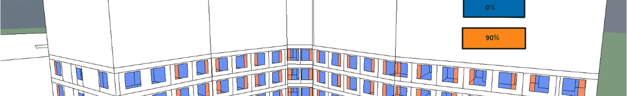
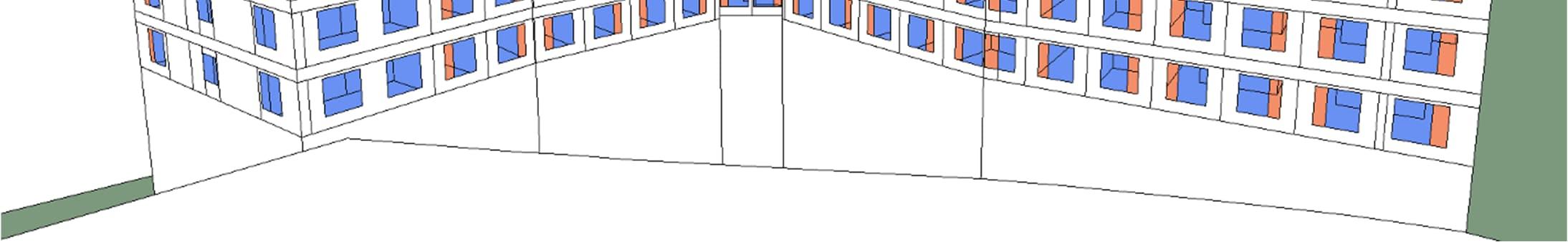


The windows opening hours have been determined according to the Building Regulation Part O and Part F guidance. The operable section of the openings have been assumed to be unobstructed. If internal blinds or curtains are provided, the design should allow for maximum ventilation as assumed in the assessment. Any restriction may affect the thermal comfort of the building.
Please see Appendix E for further details on the window openings profiles applied.
The following auxiliary ventilation rates have been specified in the analysis:
Mechanical ventilation
Type 1 – Mechanical Cooling
Rooms applied Apartments
System Type MVHR
Max air volume (l/s)
Studio Bedroom/living/kitchen - 21 l/s
Ventilation profile On continuously
Thermal bypass Heat recovery “on” if internal temperature is below 23°C
Table 10-4 Ventilation Rates
Auxiliary ventilation is considered to be operating at all times in all spaces where it has been specified. The summer ventilation supply temperature has been adjusted in the analysis to consider the use of heat recovery in all main spaces.
The passive design of the units has been considered in detail, and the orientation and massing has considered its position on the Site relative to other buildings which will provide an element of shading but also to maximise daylight opportunities. Internal layouts have also been refined to allow the daylighting requirements to be achieved without reliance on excessive amounts of glazing. Façade options have been studied to minimise heat loss and solar gains, and to investigate the introduction of external shading measures and glazing ratio optimisation.
MODELLING ASSUMPTIONS
Ventilation
Due to the location of the Proposed Development and as can be seen in the acoustic reports, the road noise exceeds the limits set in Part O for opening windows on all floors. However, both scenarios have been tested in line with the GLA cooling hierarchy.
Open window scenario – This scenario aligns with the Part O window opening schedule while ignoring the noise restrictions. In this scenario, occupants are considered to gradually open windows when the internal temperature exceeds 22°C and the room is occupied. In accordance with Building Regulations Part O, the windows will be fully open at 26°C. This simulates situations where occupants may want to accept with the road noise in order to allow fresh air into their apartment.
Closed window scenario – To demonstrate compliance with Part O and to simulate situations where occupants do not accept the road noise, this scenario models all windows as closed at all times when noise is expected to exceed Part O limits.
MVHR is assumed to operate continuously in residential rooms to meet minimum fresh air requirements. For specific room values refer to table 6-2
An infiltration rate has been calculated based off an air permeability of 3.0 m3/h at 50 Pa, in all residential units where it is applicable.
Stairs have no mechanical ventilation only smoke extract. Shading
An effective g-value of 0.5 for North & East facing glazing and 0.35 for South & West facing glazing has been assumed, see figure 6-1
A louvred screen modelled as a having a shading coefficient of 0.1 has been introduced to mitigate the overheating effect while also providing security for the occupants when opening the windows.
All windows have an inset of 250mm creating further shading to the living spaces.

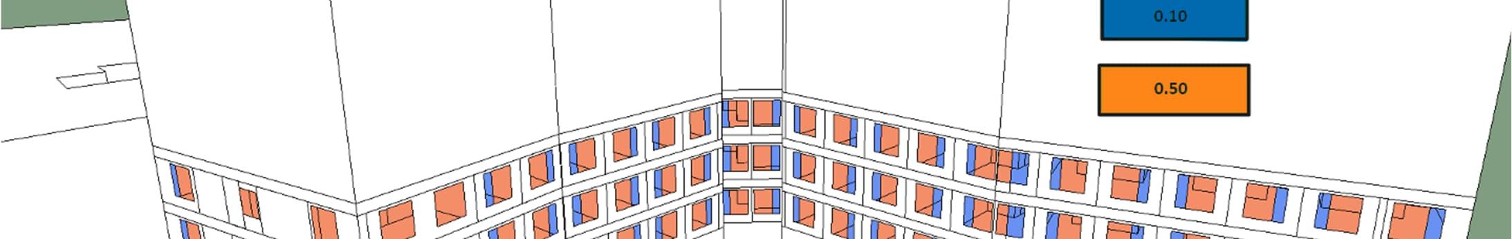
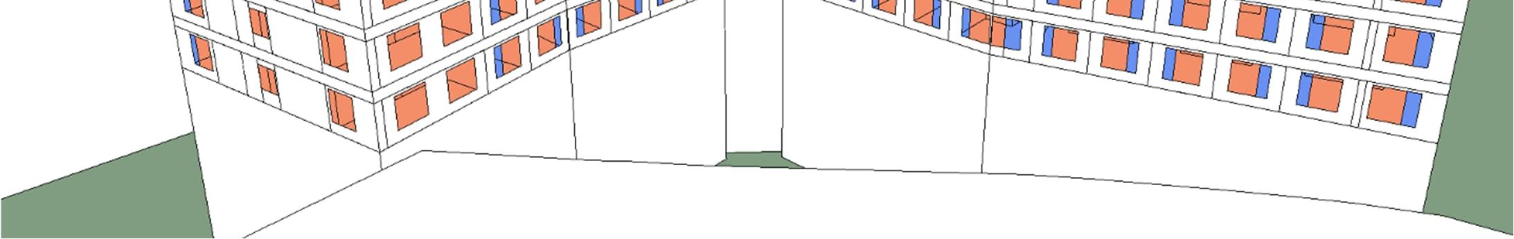
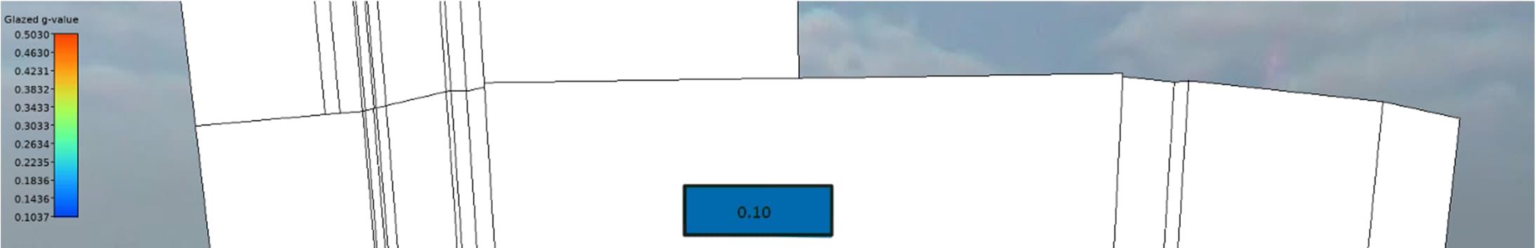
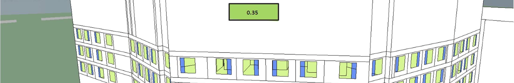

37 units within Residential Block N1 were modelled at various floor levels. The units have been selected to cover all dwelling types for both North and South Buildings as shown in Figure 10-5. The chosen floor, which includes a representative of the worst-case scenario, were assessed against Category II criteria. Overheating analysis was carried out using the three weather files as described in previously. A summary of the results is provided below.
Overheating assessment with 2020 weather file
The results for the current weather file (2020) are reported in Table 10-5. A detailed list of the results from the thermal model alongside an indication of compliance in accordance with CIBSE TM59 are reported in the Appendix A.
Criteria (a): The number of hours during which the temperature in the living rooms, kitchens and bedrooms is greater than or equal to 26⁰(K) during the period May to September (inclusive), is 3% of their occupied hours.
Criteria (b): The operative temperature in the bedrooms between 10 pm and 7 am, 26 °C for more than 3% of its annual occupied hours.
Overall, the proposed building criteria (a) and (b). The building passes TM59 therefore it complies with the Approved Building Regulation Part O for the current weather file (2020).
The full list of the results is reported in Appendix A.
Overheating assessment with 2050 weather file
Simulations were run with projected future weather data, using the representative weather file of the year 2050. Predictions leading to the development of this weather file assume a high Green House Gas (GHG) emissions scenario (high emission scenario, 50th percentile), leading to higher ambient summer temperatures. Therefore, the general overheating risk is increased compared with the 2020 file and can be seen as a good “stressing test” for the proposed design. Initial simulations using the same inputs currently proposed shown that several spaces would exceed some of
the TM59 criteria when assessed against the future weather scenario. Some potential mitigation measures that could be considered are listed below:
- Increase the windows’ glass specification potentially reducing the overall solar gains.
- Implementation of external shading elements.
- Increased mechanical ventilation rates.
- Provide some form of active cooling system.
The full list of the results is reported in Appendix B.
Table 10-5 TM59 & Part O assessment summary table based on the DSY1 2020 weather file.
Vent System Room type Room passing TM59 & Part O assessment (pass/total)
Overheating Reduction Measures Applied
Cooling
a Bedroom/living/kitchen 37/37 Criteria b Bedroom/living/kitchen 7/37
a Bedroom/living/kitchen 37/37
b Bedroom/living/kitchen 37/37
Table 10-6 TM59 & Part O assessment summary table based on the DSY 1 2050 weather file.
Vent System Room type Room passing TM59 & Part O assessment (pass/total)
Overheating Reduction Measures Applied Criteria a Bedroom/living/kitchen 4/37 Criteria b Bedroom/living/kitchen 0/37
Cooling Criteria a Bedroom/living/kitchen 37/37 Criteria b Bedroom/living/kitchen 37/37

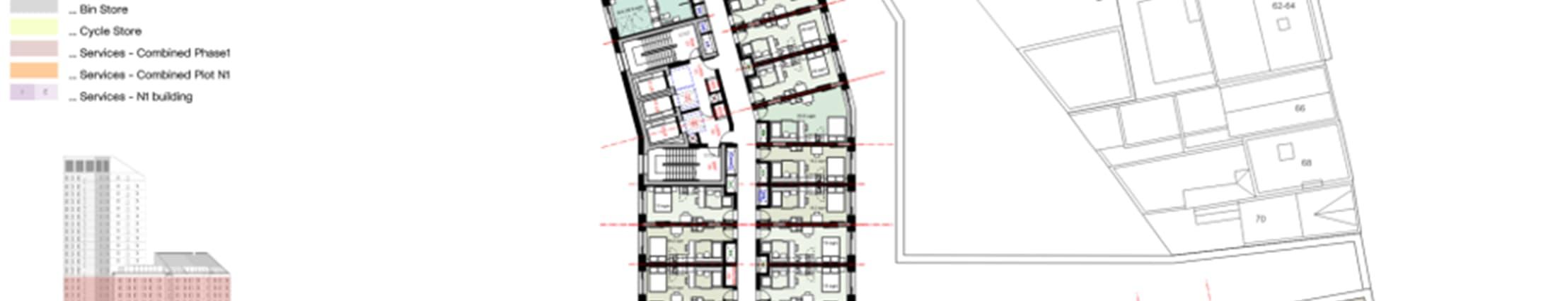

Table 10-7
Cooling Hierarchy, project measures and project performance/simulation results for occupied zones – Residential Block N2
DESCRIPTION PROJECT MEASURES THERMAL COMFORT PERFORMANCE
1.Minimise internal heat generation through energy efficient design
100% low energy LED lighting will be provided to reduce internal heat gains within the apartments. 0 of 37 spaces
In addition, it is recognised that market feedback on internal heat networks (particularly within multi storey residential buildings) in recent years has highlighted a common, significant failing: the overheating of internal corridor spaces particularly in summer. Solutions adopted to mitigate this problem include:
100% low energy lighting to reduce heat gains within the corridors.
2.Reduce the amount of heat entering a building through orientation, shading, albedo, fenestration, insulation and green roofs and walls
3.Manage the heat within the building through exposed internal thermal mass and high ceilings
4.Provide passive ventilation
The proposal for the façades include solar control glass and high thermal performance specification and insetting the windows; helping to reduce solar gain and the mean radiant temperature of the occupants. 0 of 37 spaces
Exposed ceilings were considered not suitable for the aesthetic of the residential spaces. Therefore, a passive strategy with exposed internal ceiling was not implemented for the Proposed Development.
of 37 spaces
Occupants of the residential units are considered to gradually open windows or louvres when the internal temperature exceeds 22°C and the room is occupied. 7 of 37 spaces
5.Provide mechanical ventilation Unable to increase mechanical ventilation further due to acoustic constraints within studios 7 of 37 spaces
DSY2 Weather File
DSY1 2050 Weather File
Provide Comfort Cooling
DSY2 – A summer with a short intense warm spell. An intense summer with a heat event the same length of that of DSY1, but with a higher intensity 3 of 37 spaces
DSY1 2050 – Future weather files that incorporate different climate change scenarios based off of UK climate projections 5 of 37 spaces
Higher levels of mechanical ventilation compared to the minimum Building Regulations requirements will be provided to minimise the build-up of internal gains. 37 of 37 spaces
In scenario 4, 19% of the tested spaces pass the TM59 criteria under DSY1. Due to the tight acoustic constraints of a studio bedroom increased mechanical ventilation rate (Scenario 5). Therefore, comfort cooling is required to mitigate overheating risk in alignment with TM59 and Part-O regulations and the GLA overheating hierarchy.
LTHW and DHW distribution are run vertically and not down corridor sections.
Due to minimal distribution losses, the corridors do not require to be ventilated to achieve compliance with Part O. However, there may be increased thermal comfort in these areas if the smoke shafts are utilised for environmental ventilation.
The corridors were tested in the same sample floors used for the residential units overheating analysis. Results of the analysis show overheating is not expected in the corridors.
Natural ventilation was evaluated from the early design stages. All living spaces have windows and balcony doors that can be opened, as seen in Figure 10-6 & Figure 10-7. Window areas were considered fully openable for both sections of the windows and living room balcony doors. This openable door and window area has been used to maximise ventilation and reducing daytime and nighttime overheating as much as possible.
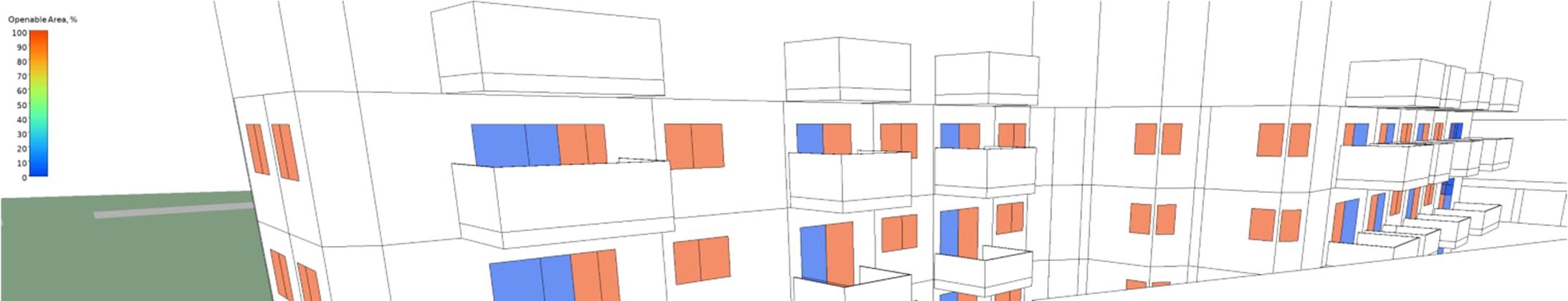

and North-Eastern angle.
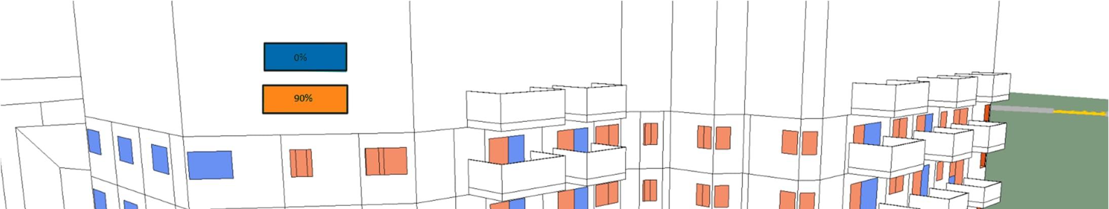
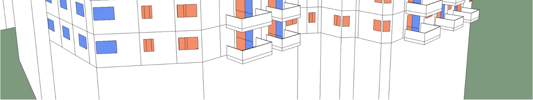
and North-Eastern angle.
The windows of the building are all assumed to be openable, and the opening hours has been determined according to the Building Regulation Part O guidance. All the openings have been assumed to be unobstructed. If internal blinds or curtains are provided, the design should allow for maximum ventilation as assumed in the assessment. Any restriction may affect the thermal comfort of the building.
The following auxiliary ventilation rates have been specified in the analysis:
Table 10-8 Ventilation Rates
Mechanical ventilation
Type 1 – Minimum Ventilation Rate
Rooms applied Apartments System
CO2 control n/a
Ventilation profile On continuously
Thermal bypass Heat recovery “on” if internal temperature is below 23°C
Type 2 – Boosted Ventilation Rate
Rooms applied Apartments
System Type MVHR
Max air volume (l/s)
Flat Kitchen/dining/living - 30 l/s Bedrooms (1) - 30 l/s/bedroom
Bedrooms (2) - 30 l/s/bedroom 3B6P Flat Kitchen/dining/living - 25 l/s
Bedrooms (3) - 25 l/s/bedroom Studio Bedroom/living/kitchen – 30 l/s
CO2 control n/a
Ventilation profile On continuously
Thermal bypass Heat recovery “on” if internal temperature is below 23°C
Auxiliary ventilation is considered to be operating at all times in all spaces where it has been specified, the ventilation systems run at the lower level and then run in boosted mode when temperatures exceed 23 degree setpoint. The summer ventilation supply temperature has been adjusted in the analysis to consider the use of heat recovery in all main spaces.
The passive design of the units has been considered in detail, and the orientation and massing has considered its position on the Site relative to other buildings which will provide an element of shading but also to maximise daylight opportunities. Internal layouts have also been refined to allow the daylighting requirements to be achieved without reliance on excessive amounts of glazing. Façade options have been studied to minimise heat loss and solar gains, and to investigate the introduction of external shading measures and glazing ratio optimisation.
Ventilation
Due to the location of the Proposed Development and as can be seen in the acoustic reports, the road noise exceeds the limits set in Part O for opening windows on all floors. However, to provide occupants the choice, two scenarios have been tested:
Open window scenario – This scenario aligns with the Part O window opening schedule while ignoring the noise restrictions. In this scenario, occupants are considered to gradually open windows when the internal temperature exceeds 22°C and the room is occupied. In accordance with Building Regulations Part O, the windows will be fully open at 26°C. This simulates situations where occupants may want to accept with the road noise in order to allow fresh air into their apartment.
Closed window scenario – To demonstrate compliance with Part O and to simulate situations where occupants do not accept the road noise, this scenario models all windows as closed at all times when noise is expected to exceed Part O limits.
MVHR is assumed to operate continuously in residential rooms to meet minimum fresh air requirements. For specific room values refer to table 6-2
An infiltration rate has been calculated based off an air permeability of 3.0 m3/h at 50 Pa, in all residential units where it is applicable.
Stairs have no mechanical ventilation only smoke extract.
Shading
An effective g-value of 0.5 for North & East facing glazing and 0.35 for South & West facing glazing has been assumed, see figure 6-1
Balconies have been introduced on the East and West faces of the building to provide amenity space and shading, see figure 6-2
All windows have an inset of 250mm creating further shading for the living spaces.
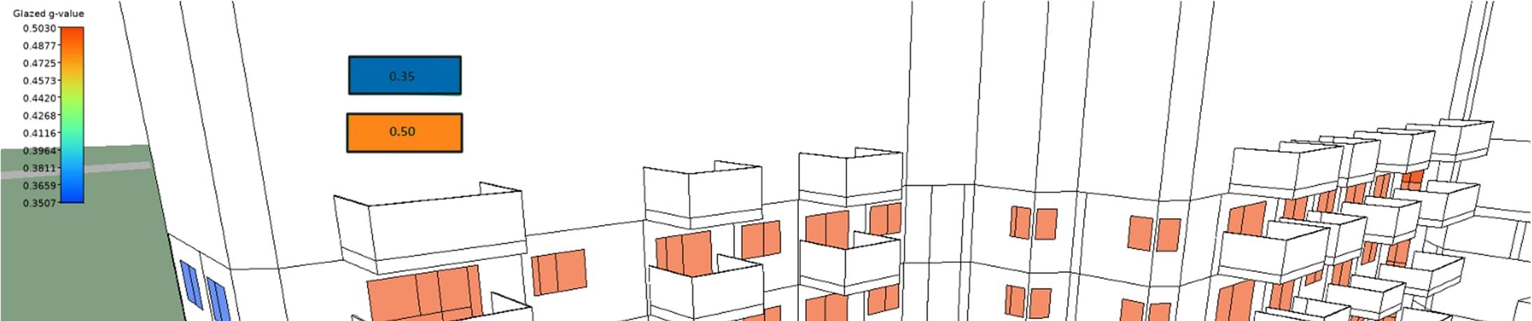
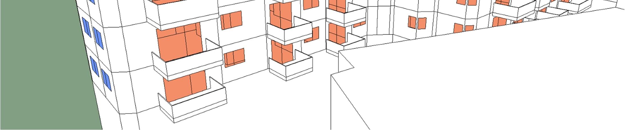
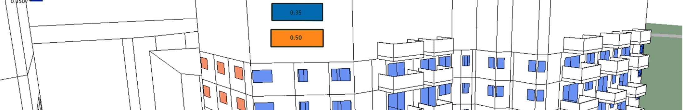
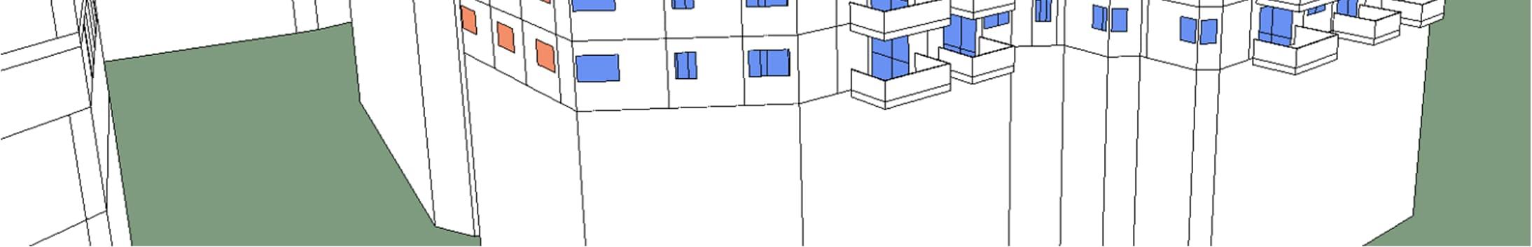

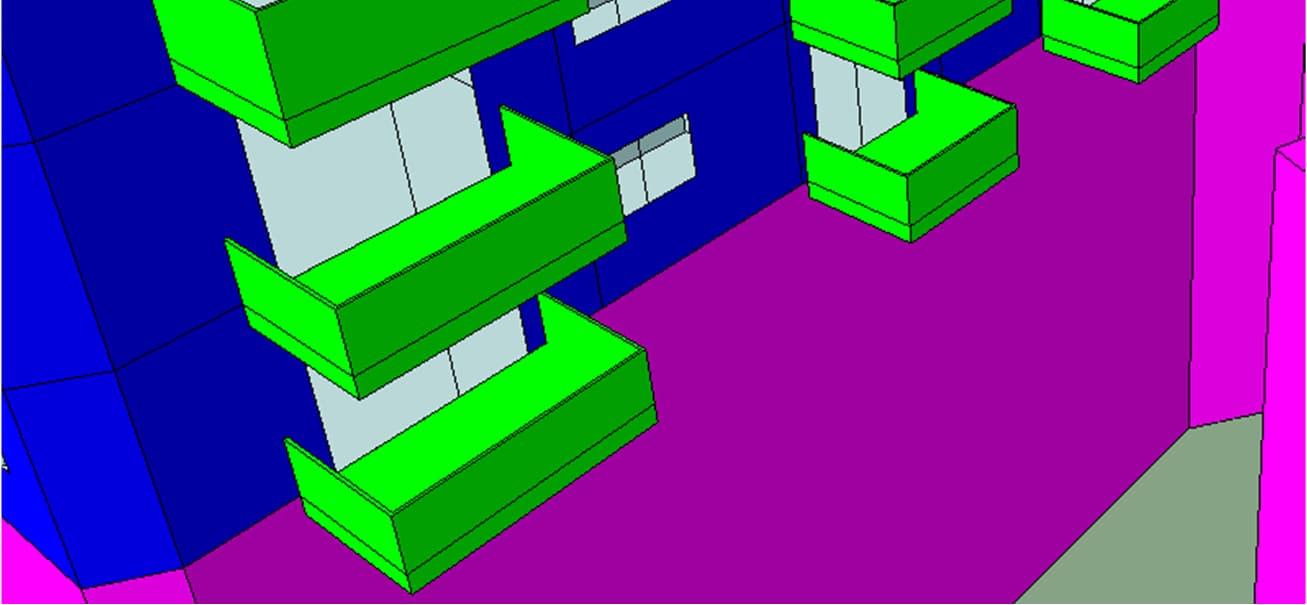
13 units within Residential Block N2 were modelled at various floor levels. The units have been selected to cover all dwelling types for both North and South Buildings as shown in Figure 10-11. The chosen floor, which include a representative of the worst-case scenario, were assessed against Category II criteria. Overheating analysis was carried out using the three weather files as described in previously. A summary of the results is provided below.
assessment
The results for the current weather file (2020) are reported in Table 10-10. A detailed list of the results from the thermal model alongside an indication of compliance in accordance with CIBSE TM59 are reported in the Appendix A.
Criteria (a): The number of hours during which the temperature in the living rooms, kitchens and bedrooms is greater than or equal to 26⁰(K) during the period May to September (inclusive), is 3% of their occupied hours.
Criteria (b): The operative temperature in the bedrooms between 10 pm and 7 am, 26 °C for more than 3% of its annual occupied hours.
Overall, the proposed building criteria (a) and (b). The building passes TM59 therefore it complies with the Approved Building Regulation Part O for the current weather file (2020).
The full list of the results is reported in Appendix A.
Simulations were run with projected future weather data, using the representative weather file of the year 2050. Predictions leading to the development of this weather file assume a high Green House Gas (GHG) emissions scenario (high emission scenario, 50th percentile), leading to higher ambient summer temperatures. Therefore, the general
overheating risk is increased compared with the 2020 file and can be seen as a good “stressing test” for the proposed design. Initial simulations using the same inputs currently proposed shown that several spaces would exceed some of the TM59 criteria. Despite not been validated some potential measure is listed below:
- Increase the windows’ glass specification potentially reducing the overall solar gains.
- Implementation of external shading elements.
- Increased mechanical ventilation rates.
- Provide some form of active cooling system.
The full list of the results is reported in Appendix B.
Vent System Room type Room passing TM59 & Part O assessment (pass/total)
Overheating Reduction Measures Applied Criteria a Living/Kitchen/Dining 10/13
Bedrooms 17/20
Criteria b Bedrooms 16/20
With Mechanical Ventilation Criteria a Living/Kitchen/Dining 13/13
Bedrooms 20/20
Criteria b Bedrooms 17/20
Table 10-9 TM59 & Part O assessment summary table based on the 2020 weather file.
Vent System Room type Room passing TM59 & Part O assessment (pass/total)
Overheating Reduction Measures Applied Criteria a Living/Kitchen/Dining 1/13
Bedrooms 17/20
Criteria b Bedrooms 0/20
With Mechanical Ventilation Criteria a Living/Kitchen/Dining 1/13
Bedrooms 17/20
Criteria b Bedrooms 0/20
Table 10-10 TM59 & Part O assessment summary table based on the 2050 weather file
10-11
spaces for the overheating analysis in Residential Block N2
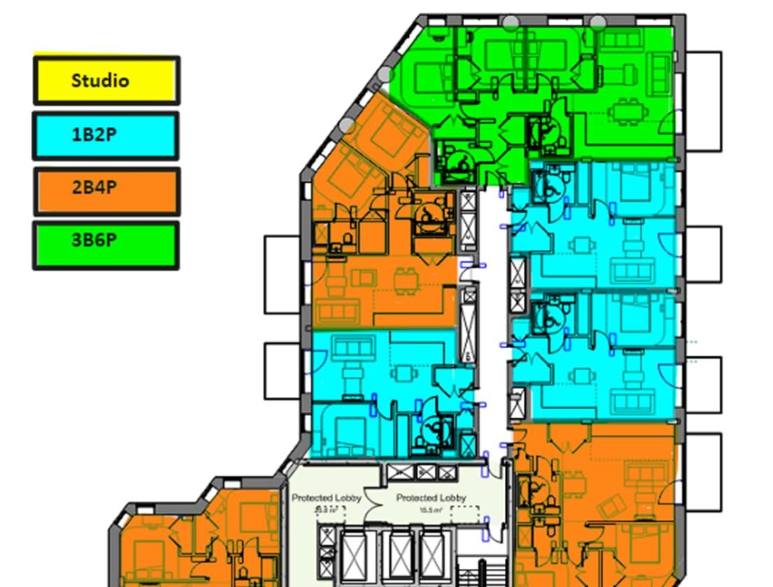
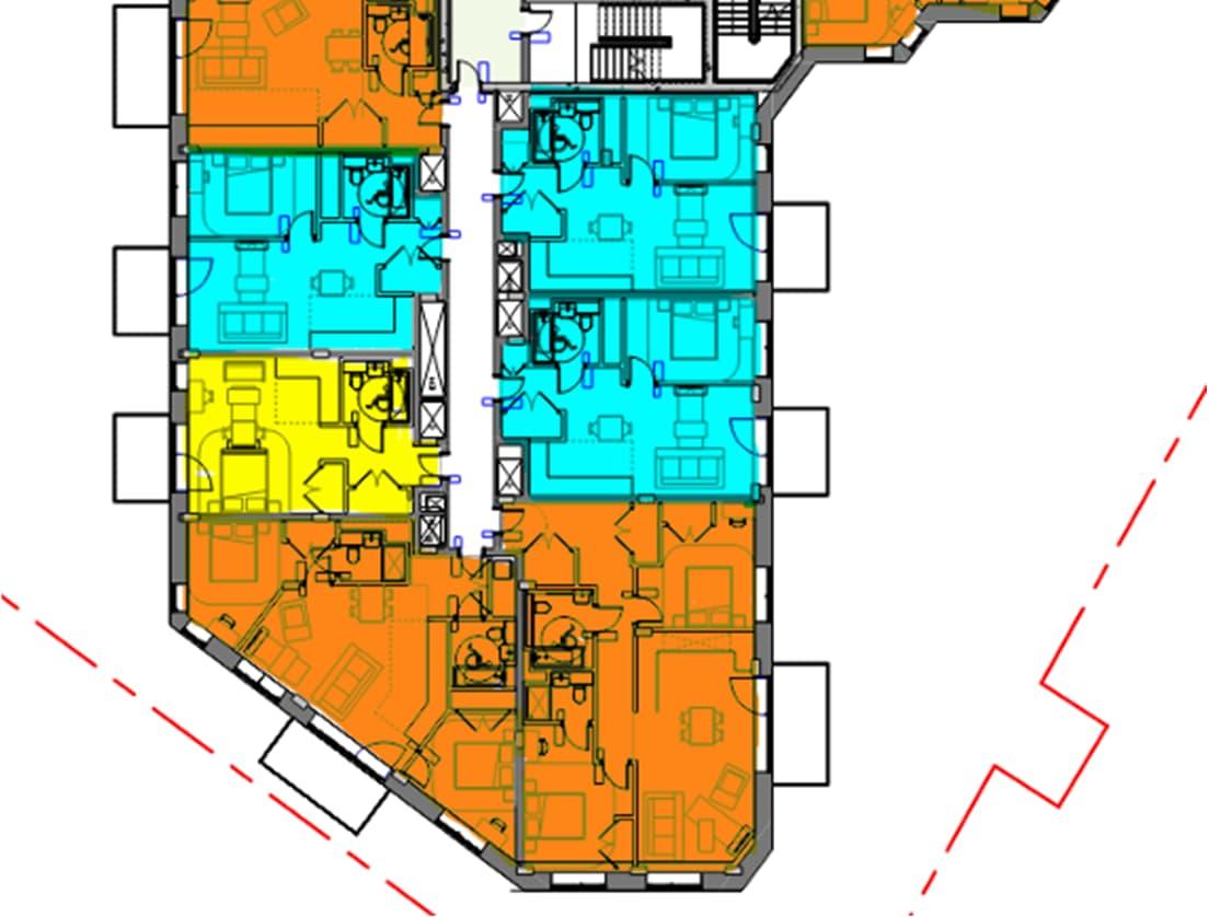
Table 10-11 Cooling Hierarchy, project measures and project performance/simulation results for occupied zones – Residential Block N2
DESCRIPTION PROJECT MEASURES
1.Minimise internal heat generation through energy efficient design
2.Reduce the amount of heat entering a building through orientation, shading, albedo, fenestration, insulation and green roofs and walls
3.Manage the heat within the building through exposed internal thermal mass and high ceilings
THERMAL COMFORT PERFORMANCE
100% low energy LED lighting will be provided to reduce internal heat gains within the apartments. 0 of 32 spaces
The proposal for the façades include solar control glass and high thermal performance specification; helping to reduce solar gain and the mean radiant temperature of the occupants. The proposed balconies and shading devices on top floors residential units will significantly reduce solar gains within the rooms behind. 0 of 32 spaces
Exposed ceilings were considered not suitable for the aesthetic of the residential spaces. Therefore, a passive strategy with exposed internal ceiling was not implemented for the Proposed Development. 0 of 32 spaces
4.Provide passive ventilation
Occupants of the residential units are considered to gradually open windows or louvres when the internal temperature exceeds 22°C and the room is occupied.
5.Provide mechanical ventilation
DSY2 Weather File
DSY1 2050 Weather File
Provide Comfort Cooling
Increased levels of mechanical ventilation compared to the minimum Building Regulations requirements will be provided to minimise the build-up of internal gains.
DSY2 – A summer with a short intense warm spell. An intense summer with a heat event the same length of that of DSY1, but with a higher intensity
DSY1 2050 – Future weather files that incorporate different climate change scenarios based off of UK climate projections
Higher levels of mechanical ventilation compared to the minimum Building Regulations requirements will be provided to minimise the build-up of internal gains.
In Scenario 4, 81% of the tested spaces pass the TM59 criteria under DSY1 without using any mechanical ventilation. Following these results, we have tested the same sample with boosted mechanical ventilation rate (Scenario 5) resulting in 91% of spaces passing. Using these Mechanical Ventilation flowrates eliminates the need for active cooling in almost all spaces apart from 3 bedrooms in the North facing façade, which passive ventilation is not a viable strategy as a result of acoustic constraints.
Overheating in Corridors
In addition, it is recognised that market feedback on internal heat networks (particularly within multi storey residential buildings) in recent years has highlighted a common, significant failing: the overheating of internal corridor spaces particularly in summer. Solutions adopted to mitigate this problem include:
100% low energy lighting to reduce heat gains within the corridors.
LTWH and DWH distribution are run vertically and not down corridor sections.
Due to minimal distribution losses, the corridors do not require to be ventilated to achieve compliance with Part O. However, there may be increased thermal comfort in these areas if the smoke shafts are utilised for environmental ventilation.
The corridors were tested in the same sample floors used for the residential units overheating analysis. Results of the analysis show overheating is not expected in the corridors.
A range of overheating studies have been undertaken in line with guidance in industry documents such as Building Regulations Part O, CIBSE TM52, CIBSE TM59 and CIBSE Guide A, and a dynamic simulation model has been developed in order to test the influence of various parameters and ensure that overheating will not be an issue.
The results ascertained from the dynamic simulation model, allow us to draw the following conclusions:
As set out in the Summary of Results above, all occupied spaces achieve temperatures within the guidelines set out in CIBSE TM59. Therefore, an acceptable level of thermal comfort has been achieved.
Overall, the proposed building criteria (a) and (b). The building therefore passes TM59 and comply with the approved building regulation Part O.
On the basis of the above, residential units are considered to comply with Building Regulations Part O, Policy SI4 of the London Plan and Part L Criterion 3 of the Building Regulations and with CIBSE TM59 and TM52.
The strategy for minimising cooling demand for the Proposed Development is as follows:
100% low energy lighting will be provided to reduce internal heat gains within the residential units.
A highly efficient fabric and glazing is proposed incorporating glazing with low-e solar shield glass on the south and west facades, to protect the interior from solar gain.
All residential units will have openable windows to allow natural ventilation.
Mechanical ventilation will be provided via MVHR to mitigate overheating.
Integrated heatpump into MVHR unit where required based on acoustic constraints.
Future proofing of system through space allowance in utility cupboard for additional cooling units to MVHR system.
The assumptions used focus on the worst-case scenario when rooms are occupied all day to take into account vulnerable people, the risk reduces when residential units are occupied only in the evening. As per TM59 guidance, the aim of this test is to encourage good design that is comfortable within sensible limits, without being so stringent that it over-promotes the use of mechanical cooling. During design development the team will look at additional opportunities to reduce the risk of overheating even further in extreme hot weather and heat wave events.
The same overheating risk mitigation strategies established for the detailed element of the planning application will be incorporated into the design of the outline element of the scheme as the design of these buildings are progressed. Future phases will undertake TM52 and TM59 assessments to assess overheating risk and follow GLA overheating hierarchy.
Reduce the amount of heat entering a building through orientation, shading, albedo, fenestration, insulation and green roofs and walls
minimise internal heat generation through energy efficient design
Manage the heat within the building through exposed internal thermal mass and high ceilings
Provide passive ventilation
Provide mechanical ventilation
Provide active cooling systems (ensuring they are the lowest carbon options).
In conclusion, this report demonstrates that the Proposed Development is compliant with the relevant policies including The National Planning Policy Framework, The London Plan, The Energy Assessment Guidance, The Development Plan and The Building Regulations Part L and Part O.
The Development has been assessed in line with the GLA Energy hierarchy:
Be Lean;
Be Clean;
Be Green; and
Be Seen.
The detailed element of the Proposed Development has been designed to include high efficiency fabric and passive design measures such as external shading. Active measures such as high efficiency heat pumps and PV panels have also been included in the design to ensure the building is all-electric and supports the UK’s decarbonisation goal.
The reductions under the GLA Energy Hierarchy have been maximised against the Part L 2021 notional building performance. The notional building is already a very energy efficient building but through collaborative engineering and design, the detailed element of the Proposed Development has incorporated solutions that results in a 71% reduction in carbon emissions compared to the notional building.
An energy assessment using the PHPP modelling tool has been carried out on the detailed element of the Proposed Development to ensure more accurately predict the operational energy. As the design progresses, the analysis will be updated to ensure the building will meet its low energy targets.
The proposals for the detailed element of the Proposed Development outlined within this energy strategy are considered to maximise the potential carbon savings which can be achieved on the Site through the provision of:
A highly efficient building fabric design to minimise heat gains and heat losses while allowing for efficient access to daylight
Low energy ventilation system including efficient heat recovery, reduced fan power and optimised control system to minimise energy consumption during operation;
PV allocation on roofs has been maximised;
100% low energy lighting, maximised use of LED and low energy fixtures
Low carbon heat provided by Air Source Heat Pumps
Smart efficient control systems and building management system will be provided to allow for efficient control and monitoring of MEP services to minimise energy waste.
Overall, the detailed element of the Proposed Development is shown to achieve the following carbon reductions after following the Energy Hierarchy of Be Lean, Be Clean and Be Green when compared to Part L 2013 using SAP10.2:
Phase 1A – 71%
Outline Scheme – 63%
The result has also been analysed using the Be Seen methodology of which preliminary operational energy analysis has been conducted using the Passivhaus Planning Package energy modelling tool.
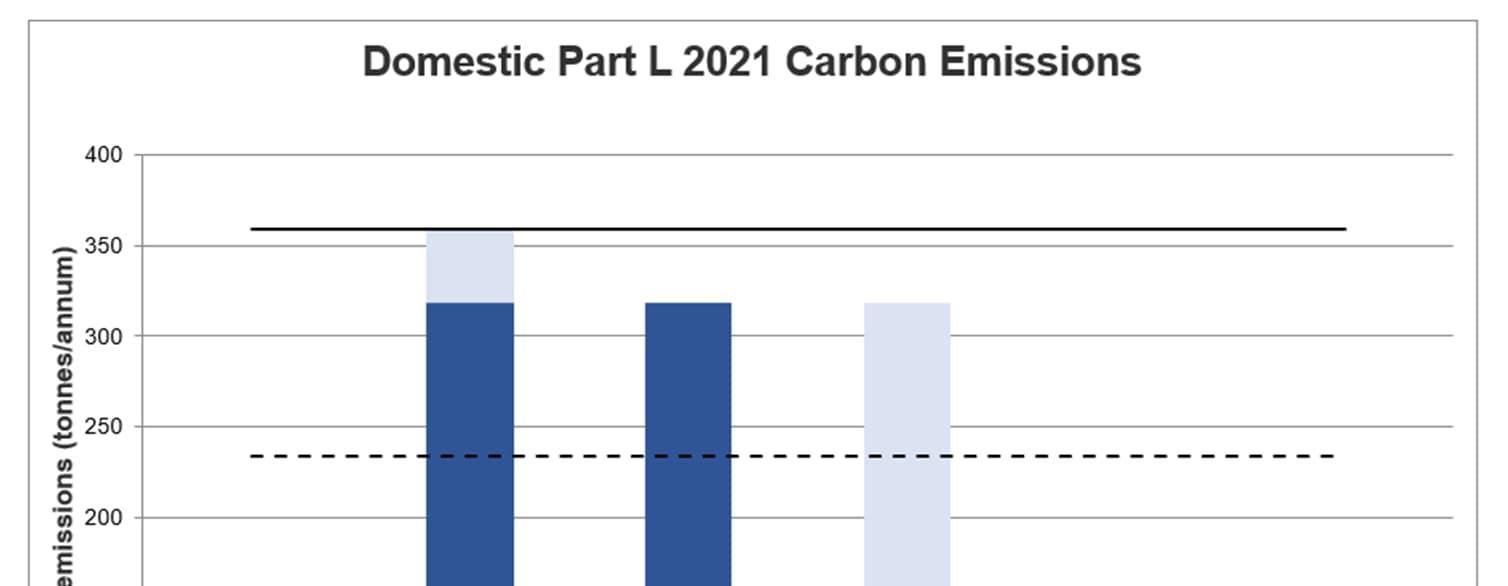
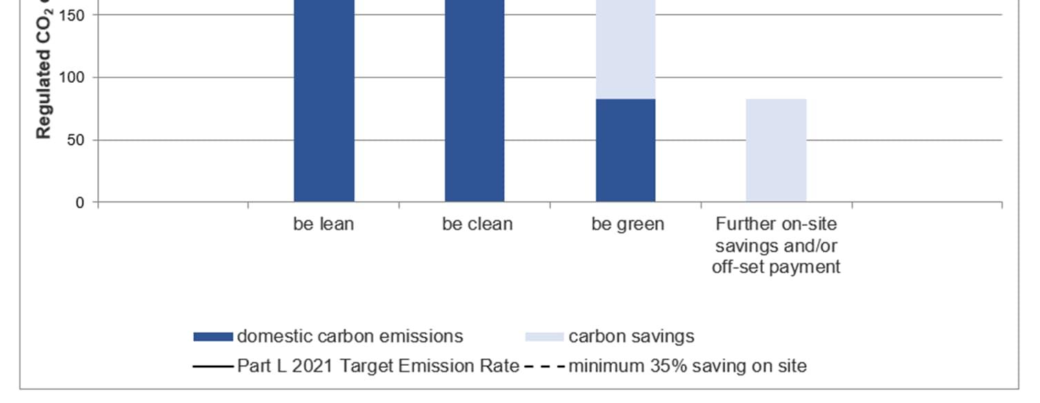
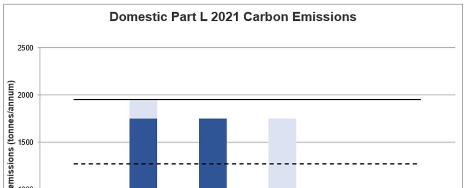
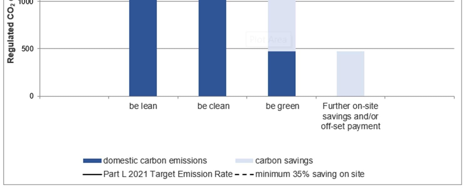
Under Policy SI2: Minimising Greenhouse Gas Emissions, where it is clearly demonstrated that the zero-carbon target cannot be fully achieved on-site, any shortfall should be provided, in agreement with the borough, either: 1) through a cash in lieu contribution to the borough’s carbon offset fund The cash-in-lieu contribution shown in
Table 8-3 is based on a price of £95/tonne for a period of 30 years according to the GLA Energy Assessment Guidance. This has been calculated based on the currently calculated carbon emissions after the application of the GLA energy hierarchy.
PERFORMANCE
Total
PERFORMANCE INDICATOR
Site cash-in-lieu contribution (detailed scheme N1 & N2 only)


EUI value from Table 4 of the guidance (kWh/m2/year) (excluding renewable energy)
Space heating demand from Table 4 of the guidance(kWh/m2/year) (excluding renewable energy)
Methodology used (e.g. ‘be seen’ methodology or an alternative predictive energy modelling methodology)
PHPP & Other (provide details in column T) dwellings / Other (provide details in column T) & Other (provide details in column T) Landlord Circulation
Explanatory notes (if expected performance differs from the Table 4 values in the guidance)
PHPP Modelling Tool & Included in PHPP model above
EUI value from Table 4 of the guidance (kWh/m2/year) (excluding renewable energy)
Space heating demand from Table 4 of the guidance(kWh/m2/year) (excluding renewable energy)
Methodology used (e.g. ‘be seen’ methodology or an alternative predictive energy modelling methodology)
Explanatory notes (if expected performance differs from the Table 4 values in the guidance)
Part L2 - approved DSM & Other (provide details in column T)
Assessment

This tool provides guidance on how to assess overheating risk in residential schemes at the early stages of design. It is specifically a pre-detail design assessment intended to help identify factors that could contribute to or mitigate the likelihood of overheating. The questions can be answered for an overall scheme or for individual units. Score zero wherever the question does not apply. Additional information is provided in the accompanying guidance, with examples of scoring and advice on next steps. Find out more information and download accompanying guidance at goodhomes.org.uk/overheating-in-new-homes
Geographical and local context
#2 Is the site likely to see an Urban Heat Island effect?
See guidance for details
Site characteristics
#3 Does the site have barriers to windows opening?
- Noise/Acoustic risks
- Poor air quality/smells e.g. near factory or car park or very busy road
- Security risks/crime
- Adjacent to heat rejection plant
Scheme characteristics and dwelling design
#4 Are the dwellings flats?
Flats often combine a number of factors contributing to overheating risk e.g. dwelling size, heat gains from surrounding areas; other dense and enclosed dwellings may be similarly affected - see guidance for examples
Solar heat gains and ventilation
#8 Do the site surroundings feature significant blue/green infrastructure?
Proximity to green spaces and large water bodies has beneficial effects on local temperatures; as guidance, this would require at least 50% of surroundings within a 100m radius to be blue/green, or a rural context
on the same facade. This reduces the potential for ventilation
#9 Are immediate surrounding surfaces in majority pale in colour, or blue/green?
Lighter surfaces reflect more heat and absorb less so their temperatures remain lower; consider horizontal and vertical surfaces within 10m of the scheme
#10 Does the site have existing tall trees or buildings that will shade solar-exposed glazed areas?
Shading onto east, south and west facing areas can reduce solar gains, but may also reduce daylight levels
#11 Do dwellings have high exposed thermal mass AND a means for secure and quiet night ventilation? Thermal mass can help slow down temperature rises, but it can also cause properties to be slower to cool, so needs to be used with care - see
#12 Do floor-to-ceiling heights allow ceiling fans, now or in the future?
Higher ceilings increase stratification and air movement, and offer the potential for ceiling fans
#13 Is there useful external shading?
Shading should apply to solar exposed (E/S/W) glazing. It may include shading devices, balconies above, facade articulation etc. See guidance on "full" and "part". Scoring depends on glazing proportions as per #6
#14 Do windows & openings support effective ventilation?
Larger, effective and secure openings will help dissipate heat - see guidance
This tool provides guidance on how to assess overheating risk in residential schemes at the early stages of design. It is specifically a pre-detail design assessment intended to help identify factors that could contribute to or mitigate the likelihood of overheating. The questions can be answered for an overall scheme or for individual units. Score zero wherever the question does not apply. Additional information is provided in the accompanying guidance, with examples of scoring and advice on next steps. Find out more information and download accompanying guidance at goodhomes.org.uk/overheating-in-new-homes
Geographical and local context
#2 Is the site likely to see an Urban Heat Island effect?
See guidance for details
Site characteristics
#3 Does the site have barriers to windows opening?
- Noise/Acoustic risks
- Poor air quality/smells e.g. near factory or car park or very busy road
- Security risks/crime
- Adjacent to heat rejection plant
Scheme characteristics and dwelling design Solar heat gains and ventilation
#4 Are the dwellings flats?
Flats often combine a number of factors contributing to overheating risk e.g. dwelling size, heat gains from surrounding areas; other dense and enclosed dwellings may be similarly affected - see guidance for examples
#8 Do the site surroundings feature significant blue/green infrastructure?
Proximity to green spaces and large water bodies has beneficial effects on local temperatures; as guidance, this would require at least 50% of surroundings within a 100m radius to be blue/green, or a rural context
on the same facade. This reduces the potential for ventilation
#9 Are immediate surrounding surfaces in majority pale in colour, or blue/green?
Lighter surfaces reflect more heat and absorb less so their temperatures remain lower; consider horizontal and vertical surfaces within 10m of the scheme
#10 Does the site have existing tall trees or buildings that will shade solar-exposed glazed areas?
Shading onto east, south and west facing areas can reduce solar gains, but may also reduce daylight levels
#11 Do dwellings have high exposed thermal mass AND a means for secure and quiet night ventilation? Thermal mass can help slow down temperature rises, but it can also cause properties to be slower to cool, so needs to be used with care - see
#12 Do floor-to-ceiling heights allow ceiling fans, now or in the future?
Higher ceilings increase stratification and air movement, and offer the potential for ceiling fans
#13 Is there useful external shading?
Shading should apply to solar exposed (E/S/W) glazing. It may include shading devices, balconies above, facade articulation etc. See guidance on "full" and "part". Scoring depends on glazing proportions as per #6
#14 Do windows & openings support effective ventilation?
Larger, effective and secure openings will help dissipate heat - see guidance