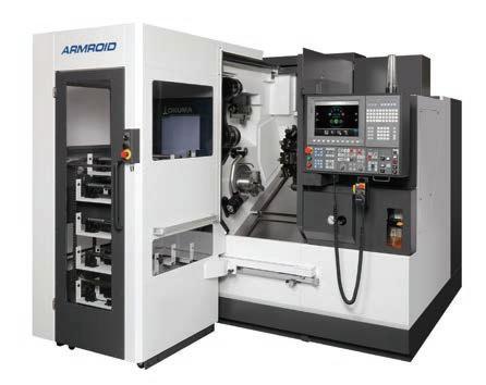
 Next-Generation Robot System
Next-Generation Robot System
Next-Generation Robot System
Robots for Tomorrow,
5 ARMROID advantages for innovative manufacturing
Point 1
Easier to use
Expertise in robotics, or robot system integrators not required
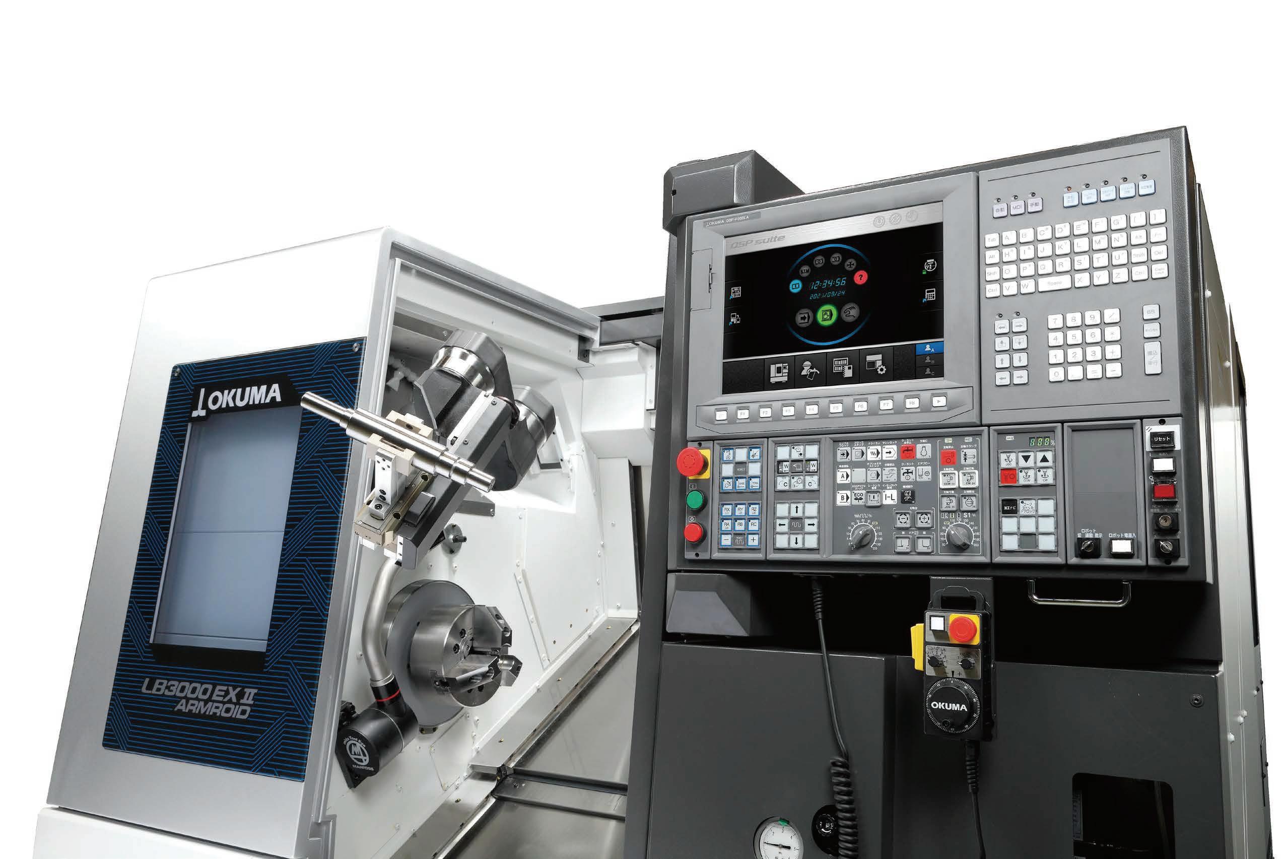
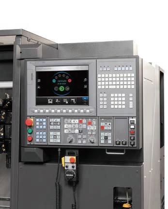
Since machine and robot are controlled by one operation panel, they can be easily handled with similar operations. By just following the guidance system for motion settings, the robot automatically generates the optimal movement path.
2
Higher functionality Point
Letting robots do the robotic human tasks

Part loading/unloading comes naturally for the robot, and it takes over the in-machine cleaning jobs as well. Moreover, providing in-process robotic support became possible—to let production continue without human interference.
1
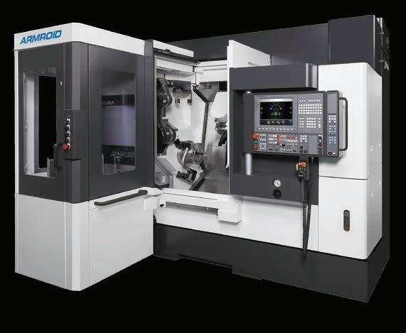
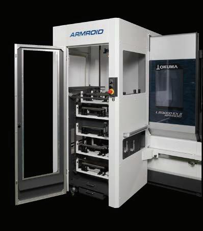
ARMROID was born from a perfect union of machine tool and robotic engineering. This next-generation robot system can fundamentally change the various issues facing manufacturing. By doing the work that was previously done by human hands, the robot will perform every job imaginable, increase productivity overall, and deliver on its promise to be the key player in tomorrow's production systems. That automation will enable humans to perform higher value-added activities, and focus on future challenges. This is what Okuma is proposing.
Humans for Future Generation s .
More flexibility Point
Human and robot work sharing
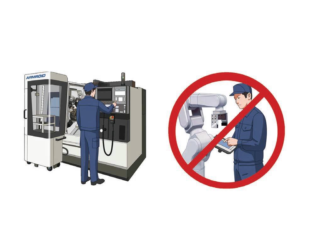
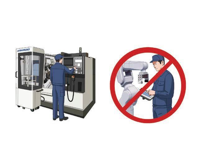
With the built-in robot and a mobile stocker, the human and robot can work with the machine and share their tasks. A variety of production applications can be configured.
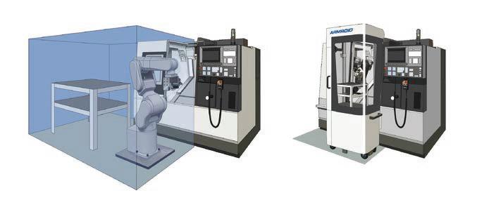
Smaller footprint Point
Additional robot floor space not required
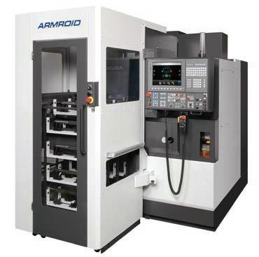
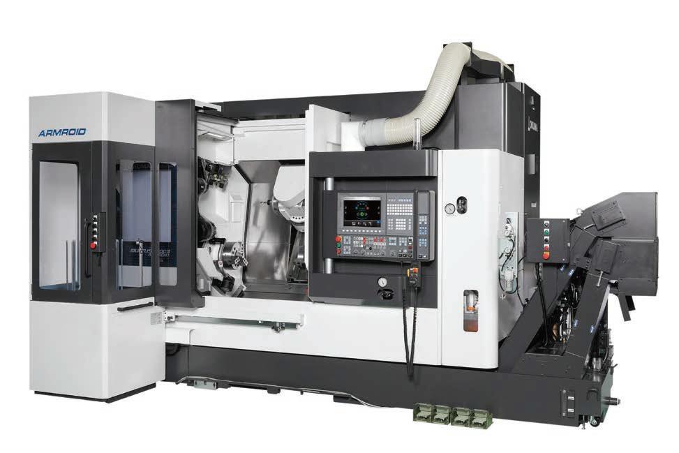
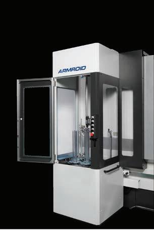
ARMROID's robot arm is built-in, so only the workpiece stocker requires space. Valuable shop floor space can be used effectively, in addition to being easy to relocate.
Lower costs Point
3 4 5
Lower investment and running costs and higher ROI
robot deployment costs ARMROID setup cost
2
Because system integrators are not required, deployment costs and time are reduced drastically. Setup changes can also be handled in-house, meaning less downtime and lower costs. Normal
ARMROID + stocker footprint
Conventional installation space
Okuma built-in robots bring more
Being simple
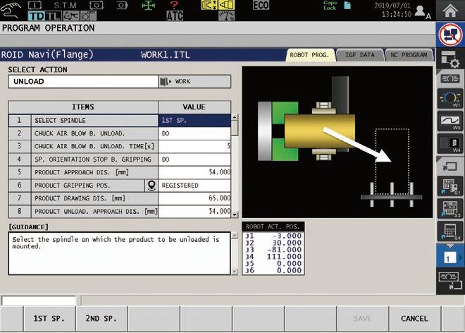
The ROID Navi was developed specifically for machine tool operators, eliminating the need for complex robot programming.
Easy machine tool or robot operation by any operator
Okuma's intelligent machine tool CNC enables real time gesture control of both the robot and machine tool.
Ease of use
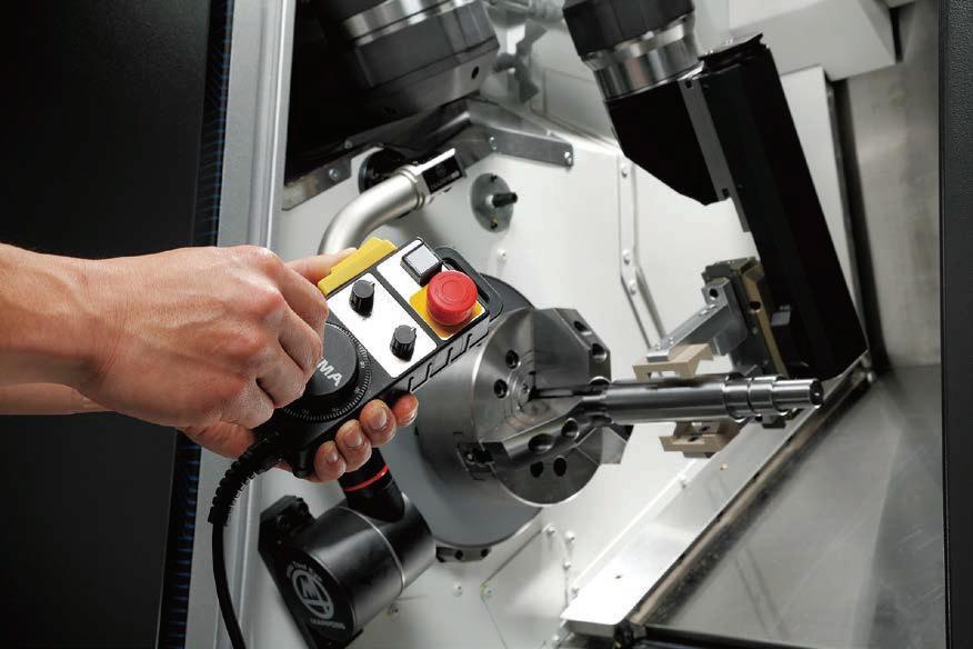
With the machine's pulse handle, robot operations can be performed easily with almost surgical precision.
Machine operation
Robot operation

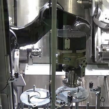
Pre-op 3D simulation to confirm robot collision avoidance.
The robot's motion program automatically generates an optimal motion path that does not collide, simply by displaying the input start and end points and the parameters according to guidance prompts. Even beginners in robotics can learn the ropes to operate from day one.
3
ROID Navi EZ Operating Tool
breakthrough innovations
A multifaceted technician
Letting robots consistently perform better than skilled machinists on routine, repetitive tasks.
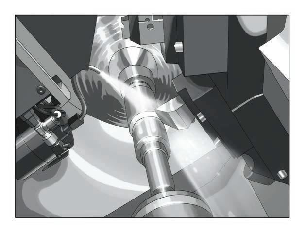
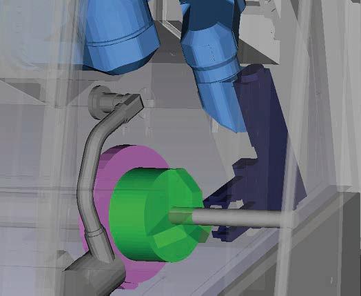
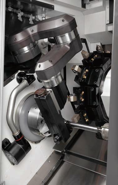
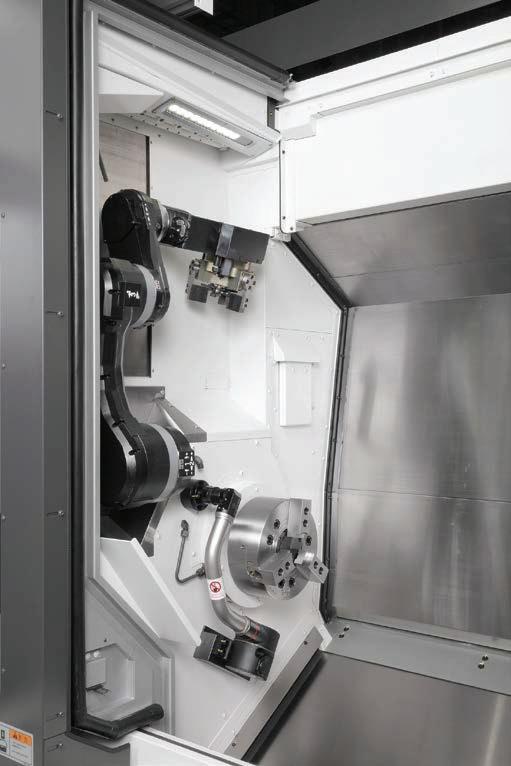
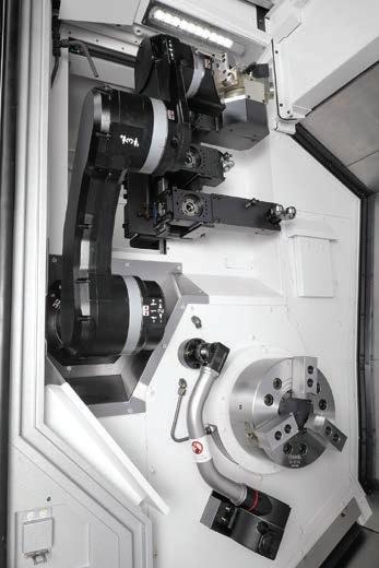
Achieve high-level processing support possible only with built-in robots
Providing in-process support in the machining chamber that is impossible with conventional robots.
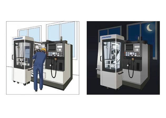
Changing the way we work
Operators work in the day and the robots work at night. Striving for zero overtime, and the coexistence of humans and robots.
Improving production efficiency through human and robot work sharing
● Easily switch from a single machine to a robot automated cell simply by adding a mobile workpiece stocker.
● For example, the robot can be on standby during the day while the operator handles small batches of part load/unload and other flexible jobs, and then automatic operations done by the robot can be done at night.
4
The workpiece stocker is positioned to the machine by pins, which can be removed to easily move the stocker.
Part load/unload Chatter suppression Chip removal In-machine cleaning
For shaft and flange workpiece Portable workpiece mass: 5/10 kg
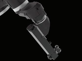
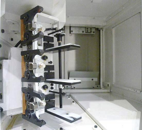
Workpiece support rollers suppress chatter during turning.
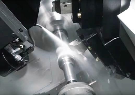
Eliminating chip entanglement by mixed blasts
Preventing chip accumulation in the machining chamber
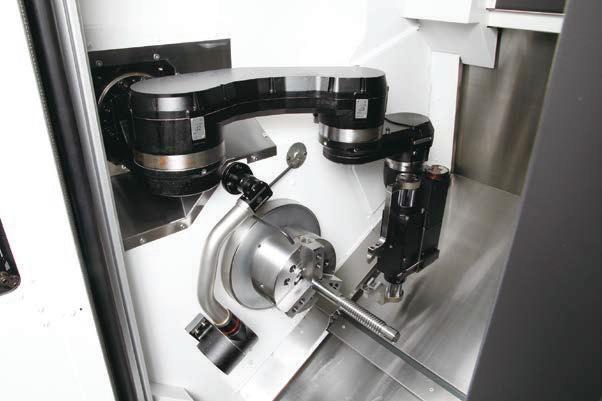
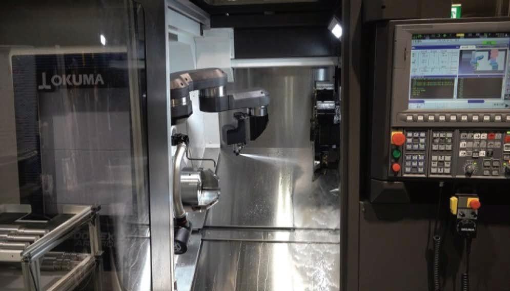
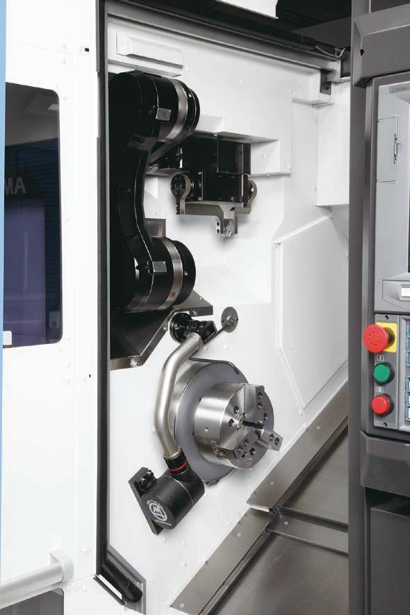
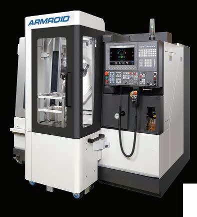
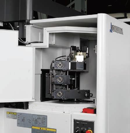
When used as a single machine, the robot stays in the standby compartment adjacent to the machining chamber.
Various configurations available
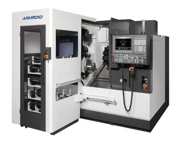
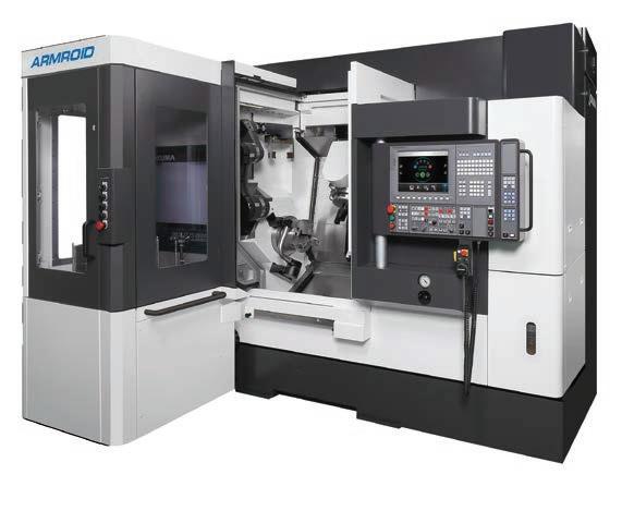
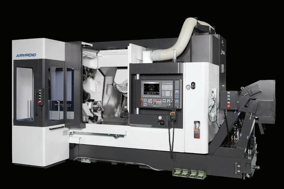
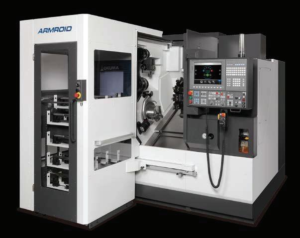
ARMROID’s lineup of applications

5
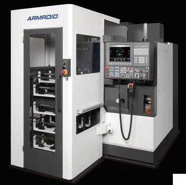
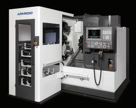
MULTUS B300II ARMROID [Multitasking Machine + Built-in Robot]
MULTUS B250II ARMROID [Multitasking Machine + Built-in Robot]
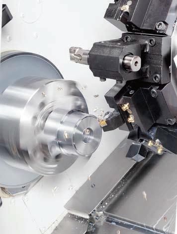
LB3000 EX II ARMROID [CNC Lathe + Built-in Robot]
to meet production needs
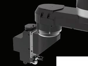
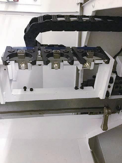
End effectors
End effector stocker
Three end effectors can be stored and changed automatically. An arrangement without storing end effectors is also available.
Workpiece support rollers
Workpiece support during machining, also suppresses
Workpiece stockers
Mixed blasting nozzles
Coolant and air blasts remove chips and clean the machining chamber while cutting.
• Simple Chutes (2-shelf)
• General-purpose rail (2-/4-shelf)
For shaft workpiece applications
Workpieces are positioned by their own weight in a rack (sloped rails or trays). Racks are available for blanks and finished parts, and are mainly used for simple shaft shapes.
• Pitch feed part conveyor (18 stations)
Shaft workpiece applications
V-shaped parts catchers are moved in a conveyor-type pitch feed mechanism. There are 18 parts catchers, and there is no contact between parts to avoid dents or scratches. Irregularly shaped shafts are also easy to handle.
• Stackable parts elevating worktable (6/10 stations)
Flange workpiece applications
Workpieces can be stacked on elevator lift plates. There are 6 or 10 stations on the worktable, and the lift plates operate in two locations for blanks and finished parts. A large number of workpieces can be stacked, to save space.
6
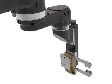
2-finger parallel gripper Shaft part loading.
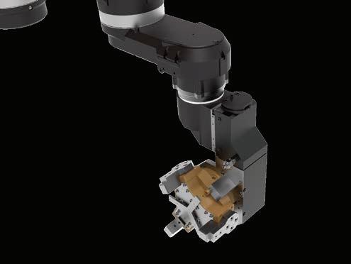
3-finger gripper Flange part loading.
chatter.
Photos show end effector stocker for the MULTUS B300II
▲ 2-shelf
▲ 4-shelf
chute
rail
■ Specifications
LB3000 EX II ARMROID
DBC: 500
Spindle: Standard / Big-Bore / Standard high power
Tailstock: AVL / NA / Sub-spindle
Y-axis control: AVL / NA
2-finger parallel
gripper
DBC: 750
Spindle: Std / Std high power
Tailstock: AVL / NA / Opp spdl
EZ Operating Tool
AVL: Available, NA: Not available
Opp spdl: Opposing spindle
DBC: 900
Spindle: Std / Big-Bore / Std high power
Tailstock: AVL / NA / Opp spdl
Air panel for ARMROID
Robot in-machine wash coolant
Pump motor output (50/60 Hz)
Auto front door open/close
Portable pulse handle with enable switch
Thermo Active Stabilizer–Construction
Collision Avoidance System
Door interlock
Auto chuck open/close
Workpiece stocker preps Optional Specifications
End effector stocker
Through-robot coolant (including filter)
ISO 10218, CE compliant
3-station
None (manual-change or fixed no-change types) available
Long stroke
2-finger parallel gripper (shafts)
3-finger gripper (flanges)
10 kg
Workpiece stocker
Chuck air blower (blast)
Tailstock air blower
Coolant sensor
Door open/close, tailstock
Mixed blasting nozzles
Workpiece support rollers
2-shelf simple chute
2-shelf general-purpose rail
Pitch feed part conveyor: 18 stations
Stackable parts elevating worktable: 6 stations
Stackable parts elevating worktable: 10 stations
Lower limit detection
*1. For LB3000 EX II ARMROID; available when the parallel gripper is 5 kg and it is not a long stroke type.
7
A101
B250
ARMROID MULTUS B300
ARMROID A201
MULTUS
II
II
ARMROID Type Standard Specifications
Machine Model Machine Specification
ROID Navi
End effector Max carrying load
End
effector
Gripper Portable workpiece mass Machining support Shaft applications Flange applications Turning/Multitasking 5 kg 5 kg 4-shelf general-purpose rail *1
advance speed change
For hydraulic quill tailstocks (shafts) 0.75/0.55 kW 1.1/0.75 kW
2-finger parallel gripper (shafts)
Long stroke 2-finger parallel gripper (shafts) 10 kg
10 kg
■ ARMROID Robot Specifications
*1. Affected by the workpiece gripping and center of gravity positions. *2. Maximum axis feed rates can not be reached in short distances. *3. Arm 1 to arm 4 mass values (base not included)
■ End Effector Specifications
Note 1. Because the robot movement range may be limited depending on the workpiece shape, the in-machine setup of the chuck, tools, etc., confirming the suitability of each workpiece will be required. The workpiece dimensions listed are only a guide, and simulator checks per operation will also be required. Note 2. Consultations with Okuma representatives required to determine support for each requested workpiece. *1. A gripper suitable for each workpiece size is required.
■ Machining Support
Mixed blasting nozzles
Mixed blasting: Alternating air/coolant application
Nozzles: 2 places
Dischargeable pressure: 0.6 MPa
Coolant pump output: 0.75/0.55 kW (60/50 Hz)
Nozzle discharge direction adjustments possible, which should be made to apply coolant on the required locations.
Workpiece support rollers
Range of diameters: ø20 to ø80 mm
Roller width / diameter: 11.2 / ø30 mm
Workpiece pressing force: 32.8 to 125.8 N
Workpiece support pressing force can be increased or decreased by the adjusting screw.
8
Fig. A101
Fig. A101 4 axes (J1, J2, J3, J4) ±0.05 mm 380˚ [±190˚ ] 92 deg/s (15.3 min-1) Electric servo drive by AC servomotor IP67 equivalent LB3000 EX II ARMROID MULTUS B250II ARMROID MULTUS B300II ARMROID Machine Model ARMROID Type Control axis Maximum payload *1 (workpiece + end effector mass) Maximum working range (End effector connector center) Repeatability Maximum working range Maximum operating speed *2 Arm mass *3 Drive system Ingress Protection rating A101 10 kg 572 mm (22.52 in) 200˚ [−121.8˚ to +78.2˚ ] 285˚ [−120˚ to +165˚ ] 238 deg/s (39.6 min-1) 48 kg A201 20 kg 669 mm (26.34 in) 200˚ [−114.9˚ to +85.1˚ ] 325˚ [−165˚ to +160˚ ] 149 deg/s (24.8 min-1) 53 kg 2-finger parallel gripper Long stroke 2-finger parallel gripper 3-finger gripper 350˚ [ 100˚ to +250˚ ] 350˚ [−130˚ to +220˚ ] Gripper ARMROID Type Workpiece shape Portable workpiece mass Clamping force 1 side effective stroke Part gripping dia *1 4-shelf general-purpose rail Gripper width A101 5 550 9 (0.35) ø20 to ø50 (ø0.79 to ø1.97) A201 10 1,200 12 (0.47) A101 5 800 22 (0.87) A201 10 1,400 32 (1.26) A201 Flange 10 1,900 9 (0.35) ø30 to ø150 (ø1.18 to ø5.91) 19 (0.75) Shaft ø20 to ø80 (ø0.79 to ø3.15) 30 (1.18) ø296.5 ø135 149.1 20 20 125 222 87.5 Door inside line J1 -16.7° 20 Nozzle Nozzle 314.2 194.2 83 51 91 142 Max support dia: ø80 Min support dia: ø20 Support roller (OD: ø30) End effector connector center Adjusting screw J1 J2 J3 J4 J1 J2 J3 J4 kg N mm (in) mm (in) mm (in) mm (in) Unit: mm Unit: mm
■ ARMROID (A101) Robot Dimensional Drawing
■ LB3000 EX II ARMROID (A101) Robot Working Range Drawing
■ LB3000 EX II ARMROID (A101) 2-Finger Parallel Gripper Range of Motion Drawing
Note: Please contact an Okuma representative for the suitability of each workpiece application, which may require further consultations.
9
Unit: mm
Unit:
mm
Unit:
Cover line 269.3(arm2length) 100 122 140 21.8° 176 140 End effector connector center Base Arm 1 Arm 2 J2 J3 J4 J1 Arm 3 Arm 4 33.7 73 230 250 221.5 280.5 222 74 46 74 30 87 51 128.5 End effector connector center 80 55 70 125 572.3 (140) 572.3 312 -121.8° -190° +190° +165° +78.2° -120° R167.5 R499.3 R161.9 R230 R230 248.6 3.9 End effector connector center range of motion J4 range of motion A2-6 nose position J3 range of motion R230 X Z R269.3 R572.3 R595.9 99.8 406 553 230 125 416.2 73 33.7 250 306.2 422.9 +250° -100° 30° Y X Front door inside line A View 627 100 3.9 103 687.7 90.9 99.8 (381.05 R269.3 R499.3 200 170 23 82 53.05 J3 position 385 Tailstock retract limit 327.3 (Possible range of robot
from the spindle centerline.) ø 80 J4 center J4 range of motion A 200.9 422.9 222 440 J10° 102.3 99.8 (381.05) Turret 30° Y X 548.2 (Possible range of robot motion from the spindle centerline.) J1 0°pos
mm
motion
222
■ ARMROID (A201) Robot Dimensional Drawing
■ LB3000 EX II
(A201) Robot Working Range Drawing
■ LB3000 EX II
(A201) 3-Finger Gripper Range of Motion Drawing
Note: Please contact an Okuma representative for the suitability of each workpiece application, which may require further consultations.
10
Unit: mm
Unit: mm
ARMROID
Unit: mm 80 56 52 108 End effector connector center Cover line
152 100 134 183 124 14.9° 108 98 28 Base Arm 1 Arm 2 Arm 3 Arm 4 33.7 74 207 375 201.5 275 219 79 109 60.5 59 30 End effector connector center 28.5 30 J2 J3 J4 J1 669.1 23.9 228.6 (140) 669.1 -114.9° +85.1° +160° +190° -165° -190° R207 R281 R595.1 R669.1 R388.1 R181.1 A2-6 nose position R281 R207 R207 R207 R248.5 X Z 247 238 485 388.3 +250° 656 33.7 375 (11.975)(455.286) 207 74 219 -100° R691.6 Y X 30° 627 R388.1 185.8 Robot range of motion 145.15 30.5 147 103 150 (Max workpiece length) 238 (381.05 R595.1 200 82 J3 position J4 center 64° J2=0° 23.9 687.7 24.2° 31° Tailstock retract limit ø 150 A 205.4 238 219 169.3 388.3 440 J10° (381.05) Turret Front door inside line 30° End effector connector center range of motion J4 range of motion J3 range of motion J4 range of motion A View J10° pos
ARMROID
388.1(arm2length)
Y X
11 ■ MULTUS B250II /B300II ARMROID (A201) Robot
■ MULTUS B250II /B300II ARMROID (A201) 3-Finger Gripper Range of Motion Drawing Unit: mm Unit: mm 669.1 5.2 228.6 (140) 669.1 -114.9° +85.1° +160° +190° -165° -190° R207 R281 R595.1 R669.1 R388.1 R181.1 R281 R207 R207 R207 X Z R248.5 415.7 480 247 656 33.7 375 207 74 312 240 60° -130° +220° R691.6 X Y Cover line
B300II turret,
from
B250II
282.1 103 5.2 150 150 (Max workpiece length) 898 (1,078*) (1,148.7*) 185 R770.9 R585.1 R595.1 Linear range of motion Tailstock retract limit Tailstock interference limit ø 1 50 J4 range of motion 984 219 169.3 388.3 Front door inside line 36° J10° J1-36° 240 415.7 282.1 67.8 ø150 30 ° A X Y End effector connector center range of motion J4 range of motion A2-6 nose position J3 range of motion A View Note: Please contact an Okuma representative for the suitability of each workpiece application, which may require further consultations. J1 0°pos 219
Working Range Drawing
* MULTUS
tailstock positions differ
MULTUS
positions.
■ End Effector Stocker Specifications
End effector stocker (equipped)
End effector stocker (not equipped)
Stores up to 3 end effectors; auto changeable with robot
End effector changes possible by the operator
End effector change not possible
■ End effector storage positions and gripper arrangements
LB3000 EX II
[End effectors removed]
MULTUS B250II /B300II [End effectors removed]
■ End Effector Storage Positions
2-finger parallel gripper
2-finger parallel gripper; long stroke 3-finger gripper
Mixed blasting nozzles
Workpiece support rollers
Storage positions cannot be changed, but MULTUS B250II/B300II station No.1 and 3 can store the same grippers. In that case, station No. 2 can not be used to store an end effector.
■ Workpiece Stocker Specifications
2-finger parallel gripper
2-finger parallel gripper (long
General-Purpose Rails Rail
Shaft
2-finger parallel gripper
in)
Simple chutes Pitch feed part conveyor Stackable worktable
Lift plates for blanks/finished parts (2 plcs) Flange
(workpieces not included)
Remarks
5 kg 230 kg
2-finger parallel gripper
2-finger parallel gripper (long stroke)
Tray 10 kg 220 kg
Workpiece length limited to machine work envelope (stocker max: 440 mm).
Blank shapes must be able to roll smoothly in the guides.
Workpiece contact may cause dents and scratches.
Loadable number of pieces depends on the maximum workpiece size.
Note: Workpiece Stocker Preps available for customers preparing their own stocker.
*1. For LB3000 EX II. Not available for MULTUS B250II/B300II
*2. For MULTUS B250II/B300II. Not available for LB3000 EX II
Cradle
3-finger gripper
Elevating lift plates to ø150 × L150 mm (ø5.91 × L5.91 in )
Guide length: 450 mm (17.72 in)
Assure stable workpiece stacking. Avoid workpiece jamming.
Use High Accuracy Lift Plate Positioning for workpieces thinner than 20 mm.
Workpiece contact may cause dents and scratches.
12
No. 2 Station No. 3
Station No. 1 Any one effector Station
Stocker Type Workpiece shapes Applicable gripper Method Workpiece size Loadable number of pieces Workpiece mass Stocker mass to ø80 mm (ø3.15 in) 10 kg 220 kg to ø80 mm (ø3.15 in) 2 shelves Blanks/finished parts (1 shelf ea) 4 shelves*1 Blanks/finished parts (2 ea) 2 shelves Blanks/finished parts (1 shelf ea) 18 stations Blanks/finished parts (dual) 6 stations 6 stations 400 kg 10 stations*2 10 stations 500 kg 1 shelf × 4 pcs Chute L: 320 mm (12.60 in) 1 shelf × 3 pcs Chute L: 300 mm (11.81 in) 18 pcs 10 kg 700 kg 10 kg Max 30 kg per station 2 shelves × 5 pcs Chute L: 270 mm (10.63 in)
Grippers Grippers
stroke)
to ø50 mm (ø1.97
Station No. 1 Station No. 2 Station No. 3 Manual change Fixed Station No. 1 Station No. 2 Station No. 3
Drawings
LB3000 EX II ARMROID Tailstock specs
MULTUS B250II ARMROID Opposing spindle specs
13 Unit: mm ■
Unit: mm
Dimensional / Installation
ARMROID A201 Drawing ARMROID A101 height dimensions differ (* dim). 910 150 CNC 640 1,290 40 474 Hydraulic unit Line filter 465 803 673 660 775 642 720 63 1,450 125 500 End effector stocker manual removal space Spindle cooler Power inlet (2 plcs) Workpiece stocker setup space Workpiece stocker general-purpose rail Side discharge tank removal space (When removing side discharge tank, remove the workpiece stocker.) (Workpiece stocker travel) (Front door open) 2,020 1,535 1,435 1,194 540 485 704 716 Coolant pump (1,770 mm or 1,070 mm from floor) End effector stocker Air panel 1,150 2,200 600 70 514 2,200 1,150 150 2,864 408 54 702 189 922 262 1,184 2,350 3,534 Maintenance space Workpiece stocker removal space (option) 2,145 (2,000)* Tailstock Hydraulic chuck pressure regulating valve (PRV) Chip bucket L (option) Chip conveyor L Operation panel V12 turret Headstock Lubrication unit 230 2,145 (1,985)* 2,142 (2,002)* 2,060 (1,900)* 82 (102)* 1,010 (850 )* 1,050 700 1,070 1,350 (Floor to air inlet) Floor to power inlet (bottom) Floor to power inlet (top) 1,770 2,000 67 1,320 1,232 608 2,619 414 1,320 1,734 818 2,552 Air inlet Air panel Power switch Lubricant recovery bucket CNC Magazine operation panel Manual removable cover Front door Door for end effector stocker Air panel Hydraulic unit Spindle center Oil temp controller Magazine maintenance door Operation panel Tank removal space Workpiece stocker 6-station worktable (Workpiece stocker travel) (Front door open) Separately installed filter unit Rotary movement during control cabinet maintenance 900 920 105 1,034 826 110 511 1,014 4,605 3,190 980 985 430 Power inlet 2,580 mm from floor ATC magazine (bed mounted) Air panel Air inlet 990 mm from FL (upper) 380 mm (lower) 941 2,249 824 540 195 400 100 978 2,030 1,000 2,140 70 2,210 727 535 638 645 1,030 1,010 500 50 187 180 350 870 847.5 152.5 975 Workpiece stocker retracted space for maintenance work 119 Chip conveyor L (option) Mist lube unit (option) Chip bucket L (option) H1 turret Headstock Lube unit Chip conveyor removal space 2,580 777 350 909 3,190 2,670 10 600 950 1,522 594 771 1,457 30 2,582 Opposing headstock Coolant tank 40-tool ATC magazine (option) Power inlet (side) (1,930 mm from floor) 2,994 727 2,210 978 2,030 71 907 480 1,550 1,010 1,000 20 1,050 875 1,925 300 2,280 2,378 130 72 2,580 Workpiece stocker removal space for transport equipment Workpiece stocker transport equipment removal space ø10 mm air tube connection required pressure: 0.5 to 0.7 MPa 1,350 mm from floor Workpiece stocker transport equipment
MULTUS B300II ARMROID Tailstock specs
Precautions
■ Safety Standards
The arm is a versatile manipulator capable of programmed operation of 3 axes or more, which complies with the following safety standards as an industrial robot and an industrial robot system.
· ISO 10218-1:2011 (JIS B 8433-1:2015)
Robots and Robotic Devices-Safety Requirements for Industrial Robots–Part 1: Robots ISO 10218-2:2011 (JIS B 8433-2:2015)
Robots and Robotic Devices-Safety Requirements for Industrial Robots–Part 2: Robot Systems and Integration
■ Qualifications
Qualifications may be required to operate, teach and inspect industrial robots. The laws and regulations of the country of acquisition regarding education and certification requirements outside Japan, shall be confirmed.
■ ROID Navi
The ARMROID robot uses ROID Navi and 3D model data to automatically generate arm paths and operate.
3D model data for chucks, tools, grippers, end effector, and workpiece shapes must be set correctly. If not set correctly, collisions may occur.
14
Unit: mm
1,060 340 95 2,050 665 1,461 2,140 721.1 68 NC tailstock Spindle center Air inlet 1,380 mm from floor Power inlet (top) (2,580 mm from floor) Magazine operation panel Magazine maintenance door Hydraulic unit Separately installed filter unit Rotary movement during control cabinet maintenance ATC magazine (bed mounted) Oil temp controller Operation panel Door for end effector stocker 354 794 1,030 440 259 1,030 (Door opening) 1,407 3,872 978 286 645 350 500 4,803 1,080 870 2,684 1,189 160 Workpiece stocker retracted space for maintenance work (Workpiece stocker travel) CNC (Tank removal space) 308 1,144 771 1,546 605 30 Headstock 2,930 600 45 1,228 917 Chip conveyor L (option) Mist lube unit (option) Chip bucket L (option) Lube unit Chip conveyor removal space H1 turret 3,870 350 Coolant tank 2,587 1,960 327 300 1,925 335 327 1,050 875 160 2,050 1,130 900 20 1,550 500 879 57 2,050 936 2,986 40-tool ATC magazine (option) Front door Workpiece stocker 6-station worktable Additional control cabinet Workpiece stocker transport equipment removal space Air panel
mentioned in the instruction manual and attached to the product.
When using Okuma products, always read the safety precautions
Pub.No.ARMROID-E-(6a)-200 (Feb 2022)
Note: Japan's Industrial Safety and Health Act requires that workers who "teach" industrial robots and perform inspections be required to receive special education for their work-related safety and/or health. Safety educational training should be conducted in countries other than Japan in accordance with similar laws and regulations.
are subject to change without notice.
TEL: +81-587-95-7825 FAX: +81-587-95-6074
● The specifications, illustrations, and descriptions in this brochure vary in different markets and
Oguchi-cho, Niwa-gun, Aichi 480-0193, JapanThis product is subject to the Japanese government Foreign Exchange and Foreign Trade Control Act with regard to security controlled items; whereby Okuma Corporation should be notified prior to its shipment to another country.