


Construction Standards
30571- Added Warning Tape and Compaction Test
34605 – Added Conductor and Conduit Table
34610 – Initial Issue IU w/ Service Box
34701 – Revised Conductors Based on NEC Table 310.16
35201 – Updated Conduit Sizes
Material Standards
2022 – Added Interior Dimensions and “Trade Size” Column
2170 – Added Swedge Couplers
2202 – Added 4/0 Quad
Anindividualunderground(I.U.)isasingleservicefedundergroundfromanoverhead transformermountedonaTIDpole.I.U.servicepanelsizesshallbe100ampto600amp. Forpanelsizesgreaterthan600amp,consultTIDElectricalEngineering.
YoucanhaveanI.U.serviceifyourservicepanelisclosetoexistingoverheadelectric facilities(generallylessthan300feet),orifanoverheadlineextensioncanbebuiltclose toyourpanel.
1.3.1ApplywithElectricalEngineeringatTID.Providepanellocation,voltageandload, dateneeded,andotherapplicableinformation.
1.3.2PayTIDtheI.U.connectionfeeandsignupforthemeter.
1.4.1TIDwillfieldthejob,preparedesigndrawingsandmateriallist,andwillprovide constructioninformationtoyou.
1.4.2Youwillprovideanestimateofthedateyouwillinstallyourfacilitiesandneed power,andTIDwillscheduletosetapoleifnecessary.
1.4.3Youwillacquiretheappropriatematerials,digthetrench,andinstalltheconduit andservicewire.E-mail(inspections@tid.org)orFax(209-656-2140)TIDfor inspectionpriortobackfillingthetrench.Seethe TIDInspectionRequestForm.
1.4.4Youwillneedyourpanelinspectedandtaggedbythelocalgoverninginspection authority(city,county,etc.).Ifyouaregoingtobereadyforpowerearlierorlater thanwhatyoutoldTID,pleasenotifyussothatwecanupdateourschedule.
1.4.5Whentagged,youwillneedtonotifyTIDatthenumbersabovesowecanenergize yourpanel.
TIDhasthefinalsayonmeterlocation,andsomelocationsareprohibited.Thereare requirementsformeterheightandaccessalso.See Section2 formoreinformation.
Dependingonthesizeofyourpanelandotherconditions,TIDwillinformyouofwireand conduitsizeforyourpanel.Youmustinstallthesizeandtypeofmaterialsapprovedby TID(TIDdoesnotacceptcopperservicewireorcompactedwire).Fordetailsonmaterial requirementsandwheretheycanbepurchased,see Section4 and Section5.
YourservicepanelmustbeacceptabletoTIDaswellastotheinspectingauthority.You shouldtellyoursuppliertoprovideapanelthatmeetsTID'sEUSERCrequirements,and/or consultwithTIDdirectlypriortopurchase.
Youshouldfamiliarizeyourselfwiththedrawingsandnotesinthefollowingsectionsto ensureyourinstallationworkissafeandmeetsrequirements.
Inadditiontoinstallingtheconduitandservicewire,youareresponsibletoconnectthe servicewirestoyourpanel.TIDwillconnectthemontheotherend.
IfTIDconstructionhasnotbeencompletedwithin2yearsofreceiptofacompleted application,thecustomermayberequiredtore-applyunderthethencurrentElectric ServiceRules,ElectricServiceScheduleofCharges,andotherconstructionrequirements.
Backupgeneratorsareasignificantsafetyissue.Evenasmallgeneratorthatisimproperly connectedcanresultinseriousinjuryordeathtoTIDlineworkersandcustomersandcan causesignificantdamagetofacilities.Forthisreason,TIDrequiresthatanybackup generatorsourcustomersmayusetosupplyloadthatisalsosuppliedbyTIDmustbe interconnectedviaaTID-approvedtransferswitch,suchthatthegeneratorinafail-safe mannerispreventedfromeverconnectingtoTID'ssystem.Toavoidexpensiveredesign andpanel/equipmentreplacement,pleaseprovideasinglelinediagramshowingthe proposedinterconnectionofanygenerators,anddetailedmodelandspecificationsforthe proposedtransferswitchtoTIDforapprovalpriortopurchaseofequipment.Ingeneral, TIDwillapprovetransferswitchesthataremechanicallyinterlockedthrow-overtypeknife bladeswitcheswithoutbypassprovisions,thoughalternativetransferswitchtypeswillbe consideredifadequatedetailsareprovided.
(PleasePrint)
Completealloftheinformationbelowandeithere-mail(inspections@tid.org)or fax(209-656-2140)totheTurlockIrrigationDistrictLineDepartment
AddressofInspection:
Directions:
TypeofInspectionRequested:
Owner’sName: PhoneNumber:
Contractor’sName: PhoneNumber:
AllconduitsandsubstructuresinstalledforTIDusemustbeinspectedpriorto backfilling.Failuretoobtainaninspectionwillrequiretheinstallertoexposetheburied facilitiesforinspection.
RefertotheappropriateTIDinformationbookletformaterialspecificationsand constructionstandards.Bookletsmaybeobtainedat333EastCanalDriveinTurlockor onlineat http://tid.com/power/engineering-construction

INSPECTIONS: www.tid.org/power/electrical-inspection-request/ Inspections: (209)883-8476 OR call (209) 606-0136 for questions
CUSTOMER NAME:
CONTACT NUMBER:
JOB NUMBER:
INSPECTIONS:
PRE CONSTRUCTION MEETING
TRENCH:
*Ref: 30571
PRIMARY CONDUIT:
*Ref: 30570,35201
SECONDARY CONDUIT:
*Ref: 30571,35201
WIRE:
*Ref: 30800,34701
SECONDARY BOX:
*Ref: 34805,35201
TRANSFORMER PAD:
*Ref: 35051,35054
GROUND GRID:
*Ref: 35051
REBAR:
*Ref: 35101
SECONDARY MANDRIL:
PRIMARY MANDRIL:
*Ref: 35201
PANEL:
Ref: 34815
PLACARDS:
BOLLARDS:
Ref: 35151, 35152, 35154,35155
INSPECTION TAG:
KNOX BOX:
Ref: 50510
VAULT:
Ref: 35202
JOB LOCATION:
W.O. NUMBER:
INSPECTOR: DATE:
*Reference Constriction Standards customer information sticker
*Photos will NOT be accepted in lieu of inspections
Therequirementsformeterheight,whichistheverticaldistancebetweenthecenterlineof themeterandthegroundorstandingsurface,shallbeasfollows:
48"minimum-75"maximumforsinglemeterresidential&meterpedestals
36"minimum–75”maximumallowedforcommercialmeterclustersinselfsupporting,rain-tightcabinets
Workingspaceinfrontofthemeterpermitsaccesstothemeteringinstallationand providesworkingsafetyforpersonnel.Aworkingspaceentirelyonthepropertyofthe customerisrequiredinfrontofallmetersexceptforbuildingsconstructedonzerolotlines.
Theworkingspaceistobekeptclearandunobstructedandshallnotbeusedforstorage. Whenmetersormeteringequipmentareplacedincabinetenclosures,theclearworking spaceshallextendfromtheouterfaceofthecabinet.
Theheightoftheclearworkingspaceshallbe78inchesminimumfromthestanding surface.
Thewidthoftheclearworkingspaceshallbe36inchesminimumforaonemeter installationandshallextendtheadditionalwidthnecessaryforaccesstothetotalnumber ofmeteringpanels.Thecenterlineofanymetershallnotbelessthan18inchesfromany adjacentsidewallorotherprotrudingobstruction.
Thedepthoftheclearworkingspaceshallbe36inchesminimumforservicesrated150 voltsorlesstoground.Whentheserviceisratedinexcessof150voltstoground,the depthshallbeasrequiredbyapplicableelectricalcodesorasdictatedbythephysical designandarrangementofthemeteringcubicles.
Inorderthatthemostsatisfactorymeterlocationmaybedeterminedandadequatespace provided,TIDshouldbeconsultedwhilethebuildingorresidenceisinthepreliminary planningstage.Installationofadditionalfacilitiesatthecustomer'sexpenseorfuture relocationsathisexpensemaybepreventedbyearlyconsultationwithTID.
Thefollowingbasiclocationrequirementsshallapplyinallcases:
2.3.1AlllocationsformetersandmeteringequipmentaresubjecttoTIDapproval.
2.3.2Metersshallbeaccessible(withduallockingdevicesifnecessary)duringandafter landscapingorotherbuildingconstruction.Nometershallbeenclosedbyany fencingwithoutpermissionfromanauthorizedTIDrepresentative.
2.3.3Metersandmeteringequipmentinstalledonorrecessedintheexternalsurfaceof anybuildingshallhaveaclearworkingandstandingspaceentirelyontheproperty ofthecustomerserved.Anyexceptionfromthisrequirementmustbeapprovedby TID.
2.4.1Inanylocationthatishazardoustoequipmentorpersonsorunsuitableforentry, suchas:
a.anyelevatorshaft.
b.anydoorwayorhatchway.
c. directlyoveranystairway,ramporsteps.
d.anyareaaccessibleonlythroughatrap-door,hatchway,orbymeans ofaladder.
e.anyareawherepersonnelmaycontactexposedhighvoltage conductorsorequipmentinmotion.
2.4.2Inanyplacewherevibration,moisture,excessivetemperature,fumes,ordustmay damagethemeterorinterferewithitsoperation.
2.4.3Withinorrequiringaccessthroughanybath,shower,powderortoiletroom.
2.4.4Onanyportionofabuildingwherelaterlandscaping,fencingorotherbuilding constructionwillmakethemeterinaccessible.
2.4.5Withinanyenclosedareathatcontainsorwillcontaingasmeters.
2.4.6Metersandmeteringequipmentshallnotbeinstalledwithinanylockedfacilityin whichTIDwouldbedeniedaccessatanytimeoftheday.
2.4.7Indoors.
2.4.8Outdoormetersshallnotbeinstalledwheretheywillinterferewithtraffic, sidewalks,driveways,orwheretheywillobstructtheopeningofdoorsorwindows, orinanylocationwhichmaybeconsideredhazardousorcausedamagetothe meteringequipment.
Remotemeteringisacceptableininstanceswhereanexternalpanelorswitchboardisnot utilized.
Thefollowingspecialarrangementsarerequired:
2.5.1ApplicantshallprovideanapprovedCTmountingcabinetthatcomplieswiththe previousparagraph"MeterLocations-GeneralConditions."
2.5.211/4"steelconduitbetweentheCTcabinetandmetersocket.
2.5.3Meterwillbelocatedwithin50conductorfeetofCTcabinet.
2.5.4Junctionboxesarepermittedonlyiftheycanbesealed.
2.5.5Couplingsmusthavesealscrews.
2.5.6Forspecialmeterdistancerequirement,refertoconstructionstandard50510.
Occasionallythereisneedtolocateandinstalladditionalserviceandmeteringequipment aftertheoriginallyplannedelectricserviceforabuildingisinstalledandenergized.Where possible,additionalmetersshouldbegroupedwiththoseelectricmetersalreadyinservice.
Ifmorethantwodwellingsorbuildingsarelocatedonthesamelot,consultTIDto determineacceptablemeterlocationsbeforeproceedingwiththewiringofthebuildings.
Forasingle-familydwellinglocatedbehindanotherdwellingorcommercialestablishment onaninside(non-corner)lotnotsubjecttofurthersubdivision,themetersshallbelocated adjacenttoeachotheratthebuildingclosesttothedistributionlinefromwhichservicewill besupplied.Allwiringbeyondthemeterswillbeatthecustomer'sexpense.
Formulti-dwellingbuildingsconstructedontherearofnon-commerciallots,ifpractical, andatthecustomer'srequest,TIDwillinstallseparateservicefacilitiestotherearbuilding. Themetersfortherearbuildingshallbegroupedtogetheratasuitablelocationattherear building.
Wheremetersaregroupedatacommonlocation,suchasfortwoormorehousesonalot orforamultipleoccupancybuilding,eitherresidentialornon-residential,eachmeter positionanditsdirectlyidentifiableservicedisconnectshallbeclearlyandpermanently markedbythebuildingownerorhisrepresentativetoindicatetheoccupancyserved(Per N.E.C.230-72a).Examplesofpermanentmarkingshallbeengravedplateattachedby screws,rivets,ortwo-partepoxy.Clearidentificationmeansalegibleapartmentorstreet number.Thestorenamemaybeincludedbutdoesnotconstituteacleardesignationin
itself.Apartmentorsuitenumbersmustbeonoradjacenttothedoorofeachunit.
Allmetersandenclosuresformeters,meteringequipmentandserviceentranceequipment onthelinesideofthemeterwillbesealedbyTID.TheTIDsealshallnotbebroken exceptbyanauthorizedrepresentativeofTID.Nopersonispermittedtotamper,remove, replace,orinanywayinterferewithameteroritsconnectionsasplacedbyTID.
Automaticbypassorcircuitclosingdevicesthatclosewhenthemeterisremovedfromthe socketshallnotbeused.
Manualcircuitclosingdevicesarerequiredonallserviceentranceequipmentexceeding30 ampsnameplateratingexceptdomestic,signboardsandtemporaryservice.Service entranceequipmentmustbecontinuouslyratedperU/L414.
Aself-containedmeteriscapableofcarryingthetotalcurrentatthevoltageoftheelectric servicesuppliedtothecustomer.Socketsforself-containedmetersaredirectlyconnected tothecustomer'sserviceentranceconductors,andthemeterisinsertedintothesocket. Metersocketsareavailablewithnominalratingsof100or200amperes.ContactTIDfor detailsonsingle-phase,400ampservice.
Whentheelectricserviceneedsoftheapplicantexceedtheampacityorvoltagelimitations ofaself-containedmeter,meteringtransformers,whichconnectdirectlytothecustomer's serviceentranceconductors,mustbeused.Atransformer-ratedmeteristhenconnected tothemeteringtransformerstomeasuretheenergydeliveredtothecustomer.The meteringtransformersandthetransformer-ratedmeter(s)arefurnishedandinstalledby T.I.D.
ElectricUtilityServiceEquipmentRequirementsCommittee(EUSERC)isanorganization whosepurposeistopromoteuniformelectricservicerequirementsamongtheutilities. TIDisamemberofandsupportsEUSERC.Assuch,whenanapplicantwishesservice withintheDistrictserviceareaandtheequipmentchosenmeetsEUSERC,itisunderstood, withsomespecificexceptions,thatTIDwillprovidepowertotheequipment.Checkwith theDistrictfordetails.
Switchboardsareconsideredaspecialtyitemformeteringequipment.TIDrequirestwo setsofapprovaldrawingsofsuchequipment.IfTIDtakesexceptiontotheequipment,the applicantwillbenotifiedofthechangesrequired.Shouldtheapplicantrequestserviceand theequipmentisnotacceptable,servicewillnotbeconnected.Havetheequipment checkedandapprovedpriortorequestingservice.Itwillsavetimeandheadachesfor everyoneinvolved.
TheswitchboardmustataminimummeetEUSERCrequirements.Aswitchboardservice sectionhasahingedmeterpanellocatedinfrontoftheinstrumenttransformer compartment.HingedmeterpanelsmusthaveEUSERChandlesandopenaminimumof 90 withmetersandtestswitchesmounted.Hingedmeterpanelsmustbesealable.
Forspecialmeterdistancerequirement,refertoconstructionstandard50510.
1 Service Trench Configuration
Notes:
1.1'-6" minimum non-native compacted backfill, with compaction to be not less than 95% relative compaction. A compaction test with the testing companies information: Name, Address and Contact Information may be required buy TID.
2.Backfill material to be non-rock with no clumps larger than 1" diameter.
3.Conduit size as per Construction Standard 35201.
4.Depth trench subject to be deeper to accommodate larger sweeps.
See Note 1
See Note 6
provided and installed equipment
Notes:
1.Service cable (provided by customer) is to be of sufficient length to exceed secondary level by three feet. Coil cable and tie in manner that will not damage cable.
2.After the elbow, (1) 10' straight length of conduit up the pole (no bell up) to be provided by customer.
3.TID to inform customer which quadrant of the pole the conduit is to rise.
4.TID to inspect conduit prior to backfilling.
5.All elbows to be 36" radius, schedule 40. Attach conduit straps to pole using washerhead lag screws.
6.Refer to Construction Standard 34805 for service box installation.
7.No service greater than 225kVA (480V) will be served from pole mounted transformers.
8.No more a than total of 270° [ 3 (90°) or combinations of 90° and 45°] bends in the conduits
4 O-7189-002 16 Washerhead Lag Screws
5 O-7192-004 1 J Hook
6 U-5595-XXX As Req'dUnderground Secondary Connector
7 U-5999-000 As Req'dRubber Boot for Connector (Included) Table 1Bill of Materials Provided and Installed by TID
Table 2Resource (1/0 to 4/0)
3Resource (500 Triplex or Quad)
Table 4Bill of Materials Provided and Installed by Customer
(6C) Table 5 Conduit and Conductor Size
Service Entrance Size (Amp)
30 (Maintenance Only)
60-70 (Maintenance Only)
Single Phase Three Phase
(1) #6 per Phase (Note 1) (1) #6 Neutral
(1) 1/0 per Phase (1) #6 Neutral
100-125 1/0 Triplex (Note 4)
200-225 4/0 Triplex (Notes 2, 4)
400 (2) 4/0 per Phase (1) 4/0 Neutral
600 (2) 500 per Phase (1) 350 Neutral
800 (3) 500 per Phase (1) 500 Neutral
1,000
(1) #6 per Phase (1) #6 Neutral
(1) 1/0 per Phase (1) #6 Neutral
1/0 Quadplex (Note 4)
4/0 Quadplex (Note 4)
(2) 4/0 per Phase (1) 4/0 Neutral
(2) 500 per Phase (1) 350 Neutral
(3) 500 per Phase (1) 500 Neutral
(3) 500 per Phase (1) 500 Neutral 1,200
1,400
1,600
1,800
2,000
2,500
3,000
Notes:
(3) 750 per Phase (1) 750 Neutral
(4) 750 per Phase (1) 750 Neutral
(4) 750 per Phase (2) 750 Neutral
(4) 1000 per Phase (2) 1000 Neutral
(5) 1000 per Phase (2) 1000 Neutral
(5) 1000 per Phase (2) 1000 Neutral
(6) 1000 per Phase (2) 1000 Neutral
1.Use one phase conductor and one neutral conductor for 120-volt circuits.
2.Refer to Construction Standard 30510 for service size to limit residential fault current.
3.Where voltage drop, voltage flicker, or other practical reasons necessitate, Engineering may specify a service size other than as listed above.
4.Individual conductors of appropriate size may be substituted for Triplex or Quadplex in accordance with TID Material Standard 2202.
5.All conductors shall be aluminum and are to be in accordance with TID conductor specifications.
6.Conductor ampacities referenced from latest NEC version Table 310.16
1
Compression Type Connector
2
Set Screw Type Connector
NOTES:
1.Aluminum tin plated
2.Terminal lug to carry full continuous current rating of conductor
3.NEMA bolt hole spacing is required on all connectors. Compression connectors must be long barrel type, similar to TID Stock Number U-6220-XXX.
4.On 3 phase, 400 amp and larger panel, terminal lugs shall be suitable compression type or 2 set screw type on conductor end. The lugs must have a minimum 2 bolt connection on the panel spades. See figures 1 and 2.
5.Before installation TID underground inspector must approve lugs and crimping die.
Figure 1 Plan View
Figure 2 Profile View
Secondary Conduit(s)
Service Conduit(s)
Notes:
A.The soil under the service box shall be compacted to no less than 95% relative compaction.
B.Leave approximately 3 feet of pull rope extended past conduit.
C.Leave approximately 4 feet of service conductor extended past conduit.
D.Insert conduit 2 inches inside service box.
E.All conduits are to be located against the same end of the service box.
F.The box lid must be labeled "ELECTRIC".
G.See Construction Standard 35201 for size and quantity of conduits required.
Service Entrance Panel
Service Entrance Panel Conduit
Figure 1
Notes:
Alternate Location. Use 30 Degree (max)
Sweeping Ells or Form Conduit to Fit, but Keep Angles 30 Degrees or Less (See Note 2)
Service Entrance Elbow to be Pointed Towards TID Electric Box
Typical Surface Mount
Conduit
Preferred Location
Service Entrance Elbow to be Pointed Towards TID Electric Box
Figure 2
Typical Flush Mount
1.Service entrance equipment will conform to applicable sections of the Electric Utility Service Equipment Requirements Committee (EUSERC) Standards.
2.All PVC conduits must be adequately glued and set prior to installation of conductors. Only sweeping types of bends are acceptable. Conduit that is deformed due to heating or over stressing during installation will not be acceptable.
3.Meters will be furnished and set by TID after the installation has been approved by the governing inspection agency.
4.The service entrance panel shall be mounted so that the center of the meter will be at a height between a minimum of 48 inches and a maximum of 75 inches above finished grade.
5.Grounding shall be in accordance with the National Electric Code (NEC) and local codes. TID may require that the grounding conductor be installed in EMT or cable armor to protect the conductor from mechanical damage. Use approved cast ground clamp.
6.Conduit size and schedule per TID Construction Standard 35201.
See Note 2
1 Underground Residential Service Panel Location
Notes:
1.The electrical panel shall be installed within the first five feet of the corner of the structure.
2.The electrical panel shall be installed near the corner of the structure closest to the utility trench.
3.The electrical panel shall be adjacent to other utilities.
4.The electrical panel shall be on the street side of any fences.
Pre-Fabricated Metering Pedestal
Meter & Breaker Assembly
Treated or Redwood Timber per California Administrative Code, Title 25.
Meter & Breaker Assembly
Finished Grade
Figure 1
Pre-Fabricated Metering Pedestal
Conduit Size per TID Standards
Customer Conduit
Approved Grounding Clamp Must Be Accessible. Extend Metallic Tubing or Cable Armor to Ground Rod to Protect Ground Wire From Mechanical Damage.
Ground Conductor per Code
Figure 2
Conduit Size per TID Standards
Customer Conduit
Approved Grounding Clamp Must Be Accessible. Extend Metallic Tubing or Cable Armor to Ground Rod to Protect Ground Wire From Mechanical Damage.
Ground Conductor per Code
Treated or Redwood Timber Metering Pedestal
Notes:
1.Service entrance equipment will conform to applicable sections of the Electric Utility Service Equipment Requirements Committee (EUSERC) Standards.
2.Customer shall supply panel with bus bar lugs where one set of lugs feeds all meters. Lug size and quantity will be specified by the District.
3.Meters will be furnished and set by TID after the installation has been approved by the governing inspection agency.
4.No service will be run under existing or future concrete areas.
5.All PVC conduits must be adequately glued and set prior to installation of conductors. Only sweeping type bends are acceptable.
6.See Construction Standard 30571 for trench configurations.
Redwood Hangers
Configuration May Vary
Meter and Breaker Assembly for Underground Feed
Redwood Posts per California Administrative Code, Title 25 Conduits from Panel
Service Entrance Conduit and Conductors to Service Pedestal, Size per TID Standards
Ground Conductor per Code
Approved Grounding Clamp, Must be Accessible. Extend Metallic Tubing or Cable Armor to Ground Rod to Protect Wire from Mechanical Damage.
Finished Grade
Ground Rod
Figure 1
Multiple Mobile Home Metering Using Underground Construction
Notes:
1.Service entrance equipment will conform to applicable sections of the Electric Utility Service Equipment Requirements Committee (EUSERC) Standards.
2.Customer shall supply panel and bus bar lugs where one set of lugs feeds all meters. Lug size and quantity will be specified by the District.
3.Meters will be furnished and set by TID after the installation has been approved by the governing inspection agency.
4.No service will be run under existing or future concrete areas.
5.All PVC conduits must be adequately glued and set prior to installation of conductors. Only sweeping type bends are acceptable.
6.See Construction Standard 30571 for trench configurations.
Ground Conductor per Code
Finished Grade
Approved Grounding Clamp Must be Accessible. Extend Metallic Tubing or Cable Armor to Ground Rod to Protect Ground Wire from Mechanical Damage.
Customer Service Conduit if Required
Figure 1
Multiple Metering Using Underground Construction
Configurations May Vary
Main Disconnect
Conduit Size per TID Requirements
Notes:
1.Service entrance equipment will conform to applicable sections of the Electric Utility Service Equipment Requirements Committee (EUSERC) Standards.
2.Customer shall supply panel with bus bar lugs where one set of lugs feeds all meters. Lug size and quantity will be specified by the District.
3.Meters will be furnished and set by TID after the installation has been approved by the governing inspection agency.
4.No service will be run under existing or future concrete areas.
5.All PVC conduits must be adequately glued and set prior to installation of conductors. Only sweeping type bends are acceptable.
6.Minimum meter height may be reduced to 36" when utilizing enclosed switchboards.
7.See Construction Standard 30571 for trench configurations.
Table 4Secondary/Service Conduits (Commercial type construction)
Table 5Conduit Sweep Radius
Notes:
1.There should not be more a than total of 270° [ 3 (90°) or combinations of 90° and 45°] bends in the conduits.
2.2023 NEC Table C.11 referenced for conduit fill.
3.*Sweep radius subject to change depending on trench depth and equipment
Notes:
1.Assembly to consist of box with cover.
2.Meets WUC Guide 3.6 (latest revision) unless otherwise specified.
3.Boxes and lids to meet loading requirements of Designation A-16 of ASTM C 857 (latest revision), including the "live load increase".
4.Cover shall be marked "ELECTRIC".
5.Cover provided with lifting provisions.
6.Cover shall be gray in color.
7.Cover shall be lockable using (2) penta head bolts.
8.Penta head bolts shall be 1/2-6 coil x 2.50".
9.Non-corrosive materials to be used on locking device.
10.Materials shall be ultra-violet radiation resistant.
11.Box shall be constructed of polymer based material or have a polymer ring to assist in controlling sidewall and backfill deflections.
12.Box shall have adequate soil bearing surfaces to prevent settling in firm soils at the specified loading.
13.Box to be without bottom.
14.Use X-Large box for 8 position secondary connectors
15.X-Large box 3" lid. Small and large box 2"
Table 2Replacement WUC Cover
Stock Number Box Size (in.)
U-1347-001 13 x 24
U-1367-001 17 x 30
U-1377-001 24 x 36
Replacement Cover per WUC Guide 3.6 (latest revision)
Table 3Extension
Stock Number Size (in.)
U-1368-008 17 x 30 x 8
U-1378-008 24 x 36 x 8
8" Extension Ring to Raise Box For Placement Below Box
Table 4Grade Ring
Stock Number Size (in.)
U-1348-002 13 x 24 x 2
U-1368-002 17 x 30 x 2
U-1378-002 24 x 36 x 2
2" - 3" Grade Ring WUC Guide 3.6 (latest revision) Cover Compatible
Access Cover
Bolt Down / Drag Off Single Leaf
H-20 Traffic Rated
Non-Slip Cover Finish
Galvanized Angle Frame exposed Cast-In Style TID NAme Plate
Concrete Box for Full Traffic
Notes - Concrete Boxes for Full Traffic:
1.Reinforced Concrete boxes for full traffic (H/20) must meet the requirements of the latest ASTM C-857.
2.Cover shall be lockable using non-corrosive penta head bolts (1/2-6 coil x2.50").
3.Concrete parts shall be interchangeable.
4.Covers shall have a high coefficient of friction (0.65 or better), slip resistant surface.
5.Box covers must have TID identification. The box body, cover, and extension must be labeled with the manufacturer's name and have the TID Stock Number on the inside surface.
6.All concrete parts shall be permanently identified as to the manufacturer on the inside surface.
7.All concrete parts shall be provided with four 7 8 inch diameter, 1-3 4 inch minimum deep inserts with UNC Class 2A threads.
3
2 1 2" Galvanized Angle Frame Exposed Cast-In Style
Steel Cover Not Shown for Clarity
12ea. 4"∅ DUCT (One Step Gray)
Figure1 PVCConduit
Table1PVCConduit,Schedules40&80
StockNumberDescription
U-6050-0011"Schedule80
U-6050-0022"Schedule80
U-6050-0033"Schedule80
U-6050-0044"Schedule80
U-6050-0055"Schedule80
U-6050-0066"Schedule80
U-6060-0001 2"Schedule40
U-6060-0011"Schedule40
U-6060-0022"Schedule40
U-6060-0033"Schedule40
U-6060-0044"Schedule40
U-6060-0055"Schedule40
Notes:
1.MeetsNEMATC-2
2.MeetsUL-651
3.10'lengthwithbelledendorcoupling attached
Figure2 PVCCoupling
Figure3 SwedgeCoupling
Table2PVCCoupling
StockNumberDescription
U-6090-0001 2"Coupling
U-6090-0011"Coupling
U-6090-0022"Coupling
U-6090-0033"Coupling
U-6090-0044"Coupling
U-6090-0055"Coupling
U-6090-0066"Coupling
U-6092-0022"Coupling-LongLine
U-6092-0033"Coupling-LongLine
U-6092-0044"Coupling-LongLine
U-6093-0022"Coupling-Swedge
U-6093-0033"Coupling-Swedge
U-6093-0044"Coupling-Swedge
U-6093-0045"Coupling-Swedge
U-6093-0066"Coupling-Swedge
Notes:
1.Forusewithschedules40or80
2.Meetsallspecificationsforschedules 40and80conduit
Table3PVCElbow,Schedule40
StockNumberDescription
U-6065-0033"30°elbow,36"radius,schedule40
U-6065-0044"30°elbow,36"radius,schedule40
U-6065-0055"30°elbow,36"radius,schedule40
U-6075-0022"45°elbow,18"radius,schedule40
U-6075-0033"45°elbow,36"radius,schedule40
U-6075-0044"45°elbow,36"radius,schedule40
U-6075-0055"45°elbow,36"radius,schedule40
U-6085-0011"90°elbow,53 4"radius,schedule40
U-6085-0022"90°elbow,36"radius,schedule40
U-6085-0033"90°elbow,36"radius,schedule40
U-6085-0044"90°elbow,36"radius,schedule40
U-6085-0055"90°elbow,36"radius,schedule40
U-6085-0072"90°elbow,24"radius,schedule40
U-6085-0084"90°elbow,60"radius,schedule40
U-6085-0095"90°elbow,60"radius,schedule40
U-6085-0106"90°elbow,60"radius,schedule40
Figure4 PVCElbow
Table4PVCElbow,Schedule80
StockNumberDescription
U-6063-0033"30°elbow,36"radius,schedule80
U-6063-0044"30°elbow,36"radius,schedule80
U-6063-0055"30°elbow,36"radius,schedule80
U-6070-0022"45°elbow,18"radius,schedule80
U-6070-0033"45°elbow,36"radius,schedule80
U-6070-0044"45°elbow,36"radius,schedule80
U-6070-0055"45°elbow,36"radius,schedule80
U-6080-0011"90°elbow,53 4"radius,schedule80
U-6080-0022"90°elbow,36"radius,schedule80
U-6080-0033"90°elbow,36"radius,schedule80
U-6080-0044"90°elbow,36"radius,schedule80
U-6080-0055"90°elbow,36"radius,schedule80
U-6080-0072"90°elbow,24"radius,schedule80
Notes:
1.Forusewithschedules40or80conduit.
2.Meetsallspecificationsforschedules40and80conduit.

Figure5
PVCConduit,Flexible
Figure6 PVCPowermould,Schedule40
Figure7 PVCConduittoPowermouldAdapter
Table6PVCConduit,Flexible
StockNumberDiameter(in.)
U-6150-0001 2*
U-6150-0011*
U-6150-0022
U-6150-0033
U-6150-0044
*Maintainsshape afterbending.
Notes: 1.PVCConduit,flexible,corrugated.
Table9PVCPowermould
StockNumberDiameter(in.)
U-6160-0022
U-6160-0033
U-6160-0044
U-6160-0055
Notes:
1.Schedule40. 2.10'lengthwithbelledend. 3.PerNEMAPH41,TC-19.
Table10PVCConduittoPowermouldAdapter
StockNumberAdapterSize(in.)
U-6170-0024"conduitto2"Powermould
U-6170-0046"conduitto4"Powermould
Notes: 1.PerNEMAPH41,TC-19.


Figure8
PVCRepairDuct


Figure9
PVCRepairCoupling
Table7PVCRepairDuct
StockNumberDiameter(in.)
U-6061-0022
U-6061-0033
U-6061-0044
U-6061-0055
Notes:
1.Schedule40.
2.10'section.
3.Interlockdesign.
4.Ultravioletresistant.
5.Forrepairofschedule40,schedule80,and DB120conduit.
Table8PVCRepairCoupling
StockNumberDiameter(in.)
U-6095-0022
U-6095-0033
U-6095-0044
U-6095-0055
U-6095-0066
Notes:
1.Forusewithrepairduct. 2.Interlockdesign.
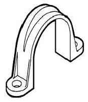
Figure10 ConduitStrap
StockNumberDiameter(in.)
U-6048-0011
U-6048-0022
U-6048-0033
U-6048-0044
U-6048-0055
U-6048-0066
Notes:
1.Hotdipgalvanized.
2.2holemounting.
3.Mountingtabsbend90°on1",2",and3"straps.
4.Mountingtabsbend30°on4"and5"straps.
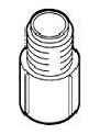
Figure11 TerminalAdapter
StockNumberDiameter(in.)
U-6180-0011
U-6180-0022
U-6180-0033
U-6180-0044
Notes:
1.Forusewithschedules40or80conduit.
2.Meetsallspecificationsofschedules40and 80conduit.
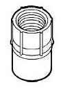
Figure12 FemaleAdapter
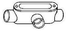
Figure13 AccessFitting,TypeT
Figure14 ServiceEntranceCap
Table14FemaleAdapter
StockNumberDiameter(in.)
U-6185-0011
U-6185-0022
U-6185-0033
U-6185-0044
Notes:
1.Forusewithschedules40or80conduit.
2.Meetsallspecificationsofschedules40and 80conduit.
Table15AccessFitting,TypeT
StockNumberDiameter(in.)
U-6190-0011
Notes:
1.Forusewithschedules40or80conduit.
2.Meetsallspecificationsofschedules40and 80conduit.
Table16ServiceEntranceCap
StockNumberDiameter(in.)
U-6200-0011
Notes:
1.Forusewithschedules40or80conduit.
2.Meetsallspecificationsofschedules40and 80conduit.

Figure15 PVCSolventCement
Table17PVCSolventCement
StockNumberSize(Qt.)
U-6140-0021
Notes: 1.Forusewithschedules40or80PVCconduit.
Figure16 BackingPlate

Table18BackingPlate
StockNumberSize(in.)
U-6165-0033
U-6165-0055
Notes: 1.10'length.
Table19ConduitCarrier
StockNumberSize(in.)
U-7325-0013/4"-1-1/4"
U-7325-0033"-4"
U-7325-0044"-6"
U-7325-0081-1/2"-2-1/2"
Notes: 1.Heavy-gaugeWaterproofwovennylon. 2.Eachinflatablelinecarrieradjuststofit conduit.
ConductorinstalledintheDistrictmustmeetcertainrequirements.Includedintherequirementsarethe conductorsize,type,strandingandinsulation.MaterialnotincompliancewillberejectedbytheDistrict inspectors.Initially,afewselectconductorswereacceptedbytheDistrict.Inanefforttohaveunderground cablemorereadilyavailableforcontractorthroughlocalsuppliers,changeshavebeenmadetoenlargethelistof acceptablecable.TurlockIrrigationDistrictstillrequiresXLPinsulation,1350aluminumalloywithstandard strandingandinsulationthickness.Thebestwaytoinsurecomplianceistospecifythecodename.
Anadditionalchangeistheacceptanceofparallelingtheconductorbythecontractor.Parallelingisinstalling threesingleconductorssimultaneouslywithoutbenefitoftheconductorsbeingintertwined;however,theneutral wiremustbepermanentlymarked.Colortape(preferablywhite)orwiretieswithlabelingisacceptableprovided itisdeterminedtobepermanentfortheneutral.
Thefollowinglistofconductorswithsize,stranding,insulationandcodenamesareacceptableforinstallationat theDistrict
1/0
500 35037,37,3736,36,3395,95,95KingsTrentonBrooklynRider 50037,37,3736,36,3695,95,95StevensJerseyCitySt.JohnsWestchester Table2Triplex/TriParallelConductorXLPECGrade1350Aluminum
2/0
4/0
#219,19,77,7,780,80,60QueensRosaryMarionBrenau 1/019,19,197,7,780,80,80PatersonLutherMontchlairBergen
1/019,19,1911,11,780,80,80 Shaw 2/019,19,1911,11,1180,80,80CaldwellLehmanBloomfieldHunter
1/019,19,1918,18,780,80,80 MolloyManhattanville
2/019,19,1918,18,1180,80,80TrinityBelmontRegisSweetbriar
4/019,19,1918,18,1880,80,80BronxGlassboroManhattanMonmouth
3504/037,37,1936,36,1895,95,80 Wesleyan
Table3Quadplex/QuadParallelConductorXLPECGrade1350Aluminum
1/0
2/0
4/0
#219,19,19,77,7,7,780,80,80,60KentCerritosPiedmontNotreDame 1/019,19,19,197,7,7,780,80,80,80CarthageKelloggSouthernPurdue
1/019,19,19,1911,11,11,780,80,80,80
2/019,19,19,1911,11,11,1180,80,80,80LycomingItascaBrandeisLafayette
2/0191880Wake Forest
4/0191880Earlham
500 35037,37,37,3736,36,36,3395,95,95,95SalesianBerryValparaisoWofford 50037,37,37,3736,36,36,3695,95,95,95CovenantCitadelMarshallLackawanna
TIDStock
Number
O-3325-008 GroundRod,8’x5/8"
KORTICK K5428 JOSLYN J8338 COOPER DN3C8
ABCHANCE C615880 ERITECH 615880 NEHRING NCC588
O-5505-001
O-5505-002
Wire,BareCopper1/0AWG SERVICE SOUTHWIRE GENERALCABLE NEHRING
Wire,BareCopper,2/0AWG SERVICE SOUTHWIRE GENERALCABLE NEHRING
O-5965-001
Wire,CoveredAAC,1000MCMXLP CodeName:FORDHAM
ALCAN PRYSMIAN NEXANS SOUTHWIRE GENERALCABLE KINGWIRE
O-5985-005 Wire,CoveredAAC,750MCMXLP CodeName:SEWANEE
ALCAN PRYSMIAN GENERALCABLE SOUTHWIRE NEXANS KINGWIRE
O-7189-002 Screws,Lag,WasherHead1/4”x2”or21/2” JOSLYN J26486.2 EMC 105
O-7370-001
GroundRodClampfor5/8”Rod
PENNUNION CAB-2 BLACKBURN JAB58H JOSLYN J8492H KORTICK K4672 CMC WB58 ERITECH HDC58R BURNDY GRC58
U-1346-008 ServiceBox(Small)13”x24”
NEWBASIS FCA132418C4036
QUAZITE/STRONGWELL PD1324Z501-17 CDR PA12-1324-18
U-1366-002 ServiceBox(Large)17”x30”
QUAZITE/STRONGWELL PD1730Z501-17 NEWBASIS FMA173018C4036 CDR PA12-1730-18
U-1366-002 ServiceBox(ExtraLarge)24”x36”
QUAZITE/STRONGWELL PD2436Z501-17 NEWBASIS FDC243618C4938 CDR PA12-2436-18
U-2054-001 TransformerPad-SinglePhase
QUAZITE/STRONGWELL PH5448BA NEWBASIS UGS-504 ARMORCAST 6001986 JENSENPRECAST
U-2056-001 TransformerPad–ThreePhase(75–500kVA)
UTILITYVAULT ByDescription&Spec NEWBASIS
TEICHERTBROOKS
QUAZITE/STRONGWELL ARMORCAST JENSENPRECAST
U-2056-005 TransformerPad–ThreePhase(750kVA&larger)
UTILITYVAULT ByDescription&Spec NEWBASIS
TEICHERTBROOKS
QUAZITE/STRONGWELL ARMORCAST JENSENPRECAST
U-2095-001 PadmountedSwitchSubstructure
TEICHERTBROOKS 0510ASYB60PSSTID UTILITYVAULT 0260014-3300080 JENSENPRECAST 4686SWITCHVAULT
U-2146-003 PullBox-Large(12,000lbloading)(48”x78”x60”)
TEICHERTBROOKS 0500ASYB60TID
UTILITYVAULT 0290405-2024120
JENSENPRECAST PB466_4878_TID
U-2146-005 PullBox–X-Large(12,000lbloading)(54”x102”x72”)
UTILITYVAULT 0260012-2024120
TEICHERTBROOKS 0510ASYB60TID
JENSENPRECAST PB4686_54102_TID
U-2178-001 ConcreteTransformerVault(48”x48”x78”)
UTILITYVAULT
ByDescription&Spec.
U-2178-002 ConcreteTransformerVaultCompleteLidAssembly
UTILITYVAULT
ByDescription&Spec.
U-2178-003 ConcreteTransformerVault6”ExtensionRing
UTILITYVAULT
ByDescription&Spec.
U-2179-001 HorizontalTransformerVault(36”x60”x54”)
TEICHERTBROOKS 0400ASYTE54LTPG JENSENPRECAST 35TRANSFORMERVAULT UTILITYVAULT 3546–TID
U-6045-001 ConduitBrace
CONTINENTAL
U-6048-001 ConduitStrap–1”
INWESCO
U-6048-002 ConduitStrap–2” INWESCO
U-6048-003
U-6048-004
U-6048-005 ConduitStrap–5”
U-6048-006 ConduitStrap–6”
U-6050-001 Conduit–1”Schedule80 CARLON 49408 JMEAGLE 4701000102 CANTEX A53BA12
U-6050-002 Conduit–2”Schedule80
CARLON 49411 JMEAGLE 4702000102 CANTEX A53CA12
U-6050-003 Conduit–3”Schedule80
CARLON 49413 JMEAGLE 4703000102 CANTEX A53DA12
U-6050-004 Conduit–4”Schedule80
CARLON 49415 JMEAGLE 4704000102 CANTEX A53EA12
U-6050-005 Conduit–5”Schedule80
CARLON 49416 JMEAGLE 4705000102 CANTEX A53FA12
U-6050-006 Conduit–6”Schedule80
CARLON 49417-010 JMEAGLE 4706000103 CANTEX A53GA12
U-6060-002 Conduit–2”Schedule40
CARLON 49011 JMEAGLE 4602000103 CANTEX A52CA12
U-6060-003 Conduit–3”Schedule40
U-6060-004
Manufacturer PartNumber
CARLON 49013 JMEAGLE 4603000103 CANTEX A52DA12
Conduit–4”Schedule40
CARLON 49015 JMEAGLE 4604000103 CANTEX A52EA12
U-6060-005 Conduit–5”Schedule40
CARLON 49016 JMEAGLE 4605000103 CANTEX A52FA12
U-6063-003
Conduit-Elbow3”30°36”RadiusSchedule80
CARLON UB6FL CANTEX 5123759 JMEAGLE 3303680
U-6063-004 Conduit-Elbow4”30°36”RadiusSchedule80
CARLON UB6FN CANTEX 5123760 JMEAGLE 4303680
U-6063-005
Conduit-Elbow5”30°36”RadiusSchedule80
CARLON UB6FP CANTEX 5123761 JMEAGLE 5303680
U-6070-002 Conduit-Elbow2”45°18”RadiusSchedule80
CARLON UB7CJ
Manufacturer PartNumber
JMEAGLE 2451880
U-6070-003 Conduit-Elbow3”45°36”RadiusSchedule80
CARLON UB7FL CANTEX 5121077 JMEAGLE 3453680
U-6070-004 Conduit-Elbow4”45°36”RadiusSchedule80
CARLON UB7FN CANTEX 5119821 JMEAGLE 4453680
U-6070-005 Conduit-Elbow5”45°36”RadiusSchedule80
CARLON UB7FP CANTEX 5119820 JMEAGLE 5453680
U-6075-002 Conduit-Elbow2”45°18”RadiusSchedule40
CARLON UA7CJ CANTEX 5133797 JMEAGLE 2451840
U-6075-003 Conduit-Elbow3”45°36”RadiusSchedule40
CARLON UA7FL CANTEX 5133779 JMEAGLE 3453640
U-6075-004 Conduit-Elbow4”45°36”RadiusSchedule40
CARLON UA7FN CANTEX 5133777 JMEAGLE 4453640
U-6075-005 Conduit-Elbow5”45°36”RadiusSchedule40
CARLON UA7FP CANTEX 5133780 JMEAGLE 5453640
U-6080-002 Conduit-Elbow2”90°24”RadiusSchedule80
CARLON UB9CJ CANTEX 5121099 JMEAGLE 2901880
U-6080-003 Conduit-Elbow3”90°36”RadiusSchedule80
CARLON UB9FL CANTEX 5121081 JMEAGLE 3903680
U-6080-004 Conduit-Elbow4”90°36”RadiusSchedule80
CARLON UB9FN CANTEX 5121023 JMEAGLE 4903680
U-6080-005 Conduit-Elbow5”90°36”RadiusSchedule80
CARLON UB9FP CANTEX 5121083 JMEAGLE 5903680
U-6085-002 Conduit-Elbow2”90°24”RadiusSchedule40
CARLON UA9CJ CANTEX 5133844 JMEAGLE 2901840
U-6085-003
U-6085-004
PartNumber
Conduit-Elbow3”90°36”RadiusSchedule40
CARLON UA9FL PWPIPE ByDescription CANTEX 5133820 JMEAGLE 3903640
Conduit-Elbow4”90°36”RadiusSchedule40
CARLON UA9FN CANTEX 5133821 JMEAGLE 4903640
U-6085-005
Conduit-Elbow5”90°36”RadiusSchedule40
CARLON UA9FP CANTEX 5133841 JMEAGLE 5903640
U-6085-006 Conduit-Elbow6”90°60”RadiusSchedule40
CARLON UA9IR CANTEX 5133886 JMEAGLE ByDescription U-6090-002
CARLON E940J JMEAGLE 60010200 KRALOY E13120 CANTEX 6141628
CARLON E940L JMEAGLE 60010300 KRALOY E13130
U-6090-004
U-6090-005
Manufacturer PartNumber
CANTEX 6141630
U-6090-006
CARLON E940N JMEAGLE 60010400 KRALOY E13140 CANTEX 6141632
U-6092-002
CARLON E940P JMEAGLE 60010500 KRALOY E13150 CANTEX 6141633
U-6092-003
CARLON E940R JMEAGLE 60010600 CANTEX 6141634
U-6092-004
CARLON E941J CANTEX 6121623 JMEAGLE 240FABCPL
CARLON E941L CANTEX 6202005 JMEAGLE 340FABCPL
CARLON E941N
U-6135-002
Manufacturer PartNumber
CANTEX 6202010 JMEAGLE 440FABCPL
Conduit–2”Plug(Cap)
CARLON P258J PWPIPE 61800200 KRALOY E35020A CANTEX 5315248
U-6135-003 Conduit–3”Plug(Cap)
CARLON P258LT PWPIPE 61800300 KRALOY E35030A CANTEX 5315260
U-6135-004
Conduit–4”Plug(Cap)
CARLON P258N PWPIPE 61800400 KRALOY E35040A CANTEX 5315252
U-6135-005
Conduit–5”Plug(Cap)
CARLON P258P PWPIPE 61800500 KRALOY E35050A CANTEX 5315253
U-6140-002 SolventCementforConduit-1qtPVCAllWeather
CARLON VC9982 WELDON DUIT427
U-6220-000 CompressionTerminalLugfor#2Wire
Manufacturer
PartNumber
ANDERSON AHL-2-BN-TP BLACKBURN AL4P HOMAC SA2NTN DOSSERT DPL6-2N-D2-EC-SN
U-6220-001 CompressionTerminalLugfor1/0Wire
PENNUNION
BLUA-1/0D3 ANDERSON
AHL-1/0-BN-TP BLACKBURN AL6P HOMAC AL1/0-NTN
U-6220-002 CompressionTerminalLugfor2/0Wire
PENNUNION
BLUA-2/0D ANDERSON
AHL-2/0-BN-TP BLACKBURN AL8P HOMAC AL2/0-NTN
U-6220-003 CompressionTerminalLugfor4/0Wire
PENNUNION
BLUA-4/0D ANDERSON
AHL-4/0-BN-TP BLACKBURN AL12P HOMAC AL4/0-NTN
U-6220-004 CompressionTerminalLugfor350MCMWire
PENNUNION
BLUA-035D ANDERSON AHL-350-BN-TP BLACKBURN AL18P HOMAC AL350-NTN
U-6220-005 CompressionTerminalLugfor500MCMWire
PENNUNION
BLUA-050D2 ANDERSON VACL-500-12BN BLACKBURN ALS4P
Number Description
Manufacturer
PartNumber
HOMAC 2081-500 MAC MUH500
U-6220-006 CompressionTerminalLugfor750MCMWire
ANDERSON AHL-750-BN-TP BLACKBURN AL44P HOMAC AL750-NTN PENNUNION KWL-079D1-P1C
U-6220-007 CompressionTerminalLugfor1000MCMWire
BURNDY YCAK44A-2G2 PENNUNION KWL-100D1-TN BLACKBURN AL60P
U-6225-004
Wire,CoveredAAC,4/0AWGXLP
CodeName:BELOIT
ALCAN PRYSMIAN
NEXANS
SOUTHWIRE CENTELSA
U-6225-007
Wire,CoveredAAC,500MCMXLPE
CodeName:EMORY
ALCAN PRYSMIAN NEXANS
SOUTHWIRE CENTELSA
U-6229-001
Cable,CoveredAAC,Triplex1/0XLPE
CodeName:BRENAU,MARIAN,QUEENS,ROSARY,PATERSON, LUTHER,MONTCHLAIR,BERGEN
ALCAN PRYSMIAN
NEXANS
SOUTHWIRE
CENTELSA
U-6229-002
Cable,CoveredAAC,Triplex2/0XLPE
CodeName:SHAW,CALDWELL,LEHMAN,BLOOMFIELD,HUNTER
ALCAN PRYSMIAN
NEXANS
SOUTHWIRE
CENTELSA
U-6229-004
Cable,CoveredAAC,Triplex4/0XLPE
CodeName:MOLLOY,MANHATTANVILLE,TRINITY,BELMONT, REGIS,SWEETBRIAR
ALCAN PRYSMIAN NEXANS
SOUTHWIRE
CENTELSA
U-6229-006
Cable,CoveredAAC,Triplex350XLPE
CodeName:WESLEYAN
ALCAN PRYSMIAN NEXANS SOUTHWIRE CENTELSA
U-6229-007
Cable,CoveredAAC,Triplex500XLPE
CodeName:RIDER,BROOKLYN,KINGS,TRENTON,STEVENS, JERSEYCITY,ST.JOHNS,WESTCHESTER
ALCAN
Manufacturer PartNumber
PRYSMIAN
NEXANS
SOUTHWIRE
CENTELSA
U-6232-001
Cable,CoveredAAC,Quadplex1/0XLPE
CodeName:NOTREDAME,PIEDMONT,CERRITOS,KENT, CARTHAGE,KELLOGG,SOUTHERNPURDUE
ALCAN PRYSMIAN NEXANS
SOUTHWIRE
U-6232-002
Cable,CoveredAAC,Quadplex2/0XLPE
CodeName:LYCOMING,ITASCA,BRANDEIS,LAFAYETTE
ALCAN PRYSMIAN
NEXANS
SOUTHWIRE
U-6232-007
Cable,CoveredAAC,Quadplex500XLPE
CodeName:WOFFORD,VALPARAISO,BERRY,SALESIAN, MARSHALL,CITADEL,LACKAWANNA,COVENANT
ALCAN PRYSMIAN NEXANS SOUTHWIRE U-6290-000 CablePullingCompound1Gallon
Manufacturer
A.C.HORN.INC DEHYDRATING6MASTIC
U-6360-001 CableProtector
PartNumber
VIRGINIAPLASTICS LG-345
ELECRICALMATERIALSCO. 27-1
CONDUX 08042300
EMCO 27-1G
U-6390-001
HeatShrinkCap(0.75”-1.50”)
T&B
HSC300-600 SIGMAFORM SSC-150
MAC ISC150 UTILCO HSC-2 3M ICEC031A RAYCHEM ESC-3/A
U-6390-002
HeatShrinkCap(1.25”-2.50”)
T&B HSC250 SIGMAFORM SSC-250
MAC ISC250 UTILCO HSC-3 3M ICEC061A RAYCHEM ESC-5/A
U-6390-003
HeatShrinkCap(1.75”-3.60”)
T&B HSC360 SIGMAFORM SSC-360 MAC ISC360 3M ICEC161A RAYCHEM ESC-6/A
U-6440-001 PowerMarker-Flat
U-6470-001 StreetLightFuseHolder
BUSS TRONHEB-JJ
U-6471-001 StreetLightFuseHolderBoots
BUSS 1A0512
U-7145-010 StreetLightFuse10Amp
BUSS BAF10
U-7145-015 StreetLightFuse15Amp
BUSS BAF15
U-7145-025 StreetLightFuse25Amp
BUSS BAF25
U-7145-030 StreetLightFuse30Amp
BUSS BAF30
U-8200-004 PullRope–3/4"
Thefollowingisalistofsupplierswhohaveindicatedthattheystockmaterialsrequiredby TID.Pleasenotethat notallmaterialsareavailablefromallsuppliers.Ifyouhave anyquestionsorproblemssourcingmaterialsrequiredbyTID,pleasecontacttheTID PurchasingDivisionat(209)883-8401.
AcmeElectric
1025S.KilroyRd. Turlock,CA95380 (209)667-2851
Contact:BusterLucas
All-PhaseElectric 2250CooperAve Merced,CA95340 (209)384-0777
ChampionWireandCable 822W.22ndSt Tempe,AZ85282 (800)329-1900 (602)736-1525
Contact:JeremyScott
ConsolidatedElectricDistributors(CED) 1343N.EmeraldAvenue Modesto,CA95351 (209)524-5591
Contact:SteveMiller
CentralWholesaleElectric 1466N.CarpenterRd Modesto,CA95351 (209)550-2500
Contact:RandyDeCicco
GraybarElectric 1211FeeDr Sacramento,CA95815 (800)388-8061ext.1947
Contact:RodRuggles
HerningUndergroundSupply
567ExchangeCt Livermore,CA94550 (925)373-8660
Contact:PatRuth:(559)994-8312
IndependentElectricSupply,Inc. 1565VentureLane Turlock,CA95380 (209)668-4702
Contact:DavidCrew
Kingwire 3030N.LambBlvdSte113 LasVegas,NV89115 (702)368-7597 (702)368-7598(fax)
Contact:Bob
PlattElectric 1431FreitasPkwy Turlock,CA95380 (209)656-1063
Contact:DeeannHarmon
RexelNorcalValley 919EmeraldAvenue Modesto,CA95351 (209)577-6611
Contact:AlexCeja
WillieElectricSupply 101S.7thStreet Modesto,CA95333 (209)527-6800
Contact:GaryBird/ToddWilson
Thefollowinglistofcompanieshavematerialonhand,haveaccesstomaterial,orwill provideyouwithadditionalsourcestolocatematerialsrequiredbytheDistrict.Order materialsinadvanceassomemayhavealeadtime.
COMPANY
NewBasis
11501DublinBlvdSte.200 Dublin,CA94568 (925)551-5019
TeichertBrooks
2441CharterWay Stockton,CA95206 (209)464-7696
ElectriGroup 4600PellDr. Sacramento,CA95838 (916)922-5550
GEXPRO
GeneralElectricSupplyCompany 4608RosevilleRd NorthHighlands,CA95660 (916)339-4521
Intraline 379BeachRd. Burlingame,CA94010 (650)340-9133
KortickManufacturingCo. 2230DavisSt. Hayward,CA94545 (510)856-3600
BRANDNAME
NewBasis
TeichertBrooks
Carlon
Carlon Cantex
Polywater Cantex J-MEagle
Kortick
Neptco P.O.Box2323
Pawtucket,RI02861-0323 (800)354-5445
Maydwell&Hartzell 2236DavisCt. Hayward,CA94545 (510)780-1700
PacificUtilities 2475EstandWay PleasantHill,CA94523 (925)674-1600
HDSupply-Benicia 6350GoodyearRd Benicia,CA94510 (800)670-7746
HDSupply-Portland 9151S.E.McBrod Portland,OR97222 (800)547-9490
WestchemEquipmentCo. 28301IndustrialBlvd. Hayward,CA94545 (510)782-3675
Neptco
Strongwell/Quazite
VirginiaPlastics
Utilco Fargo Homac Inwesco Burndy
Alcan Cantex Carlon Polywater
Inwesco
Facilitiesconstructedbyeithertheownerorhisorherbuildermustbeconstructed accordingtoTIDstandardsandapplicablelocalbuildingcodes.
IftheTIDinspectordeterminesthatanyofthecustomer/builder-installedfacilitiesdonot meetTIDstandards,theowner/builderwillberesponsibleformakingthenecessary changesathisorhercost.
TIDcannotcompletetheserviceworkuntil ALL customerworkhaspassedTIDand applicablegoverningagencies’inspections.
ThefollowingisalistofgoverningagencieswithintheTIDserviceterritory:
StanislausCountyBuildingInspectionOffice
ATTN:DeputyBuildingInspector 101010thSt.,Suite3500,Modesto95354
(Serving:Ceres,Denair,Hickman,Keyes,LaGrange&StanislausCo.) Phone:(209)525-6557
MercedCountyInspectionOffice
ATTN:ChiefBuildingOfficial 2222MSt.,Merced95340
(Serving:Ballico,Delhi,Hilmar&MercedCo.) Phone:209)385-7477
CityofHughsonBuildingDepartment
ATTN:ChiefBuildingOfficial 7001WhitmoreAve.#8 Hughson,CA.95326
(Serving:CityofHughson) Phone:(209)883-0811
CityofModestoBuildingInspectionDepartment 101010thSt.,Suite3100,Modesto95354
(Serving:CityofModesto) Phone:(209)577-5232
CityofPattersonCommunityDevelopmentDepartment BuildingDivision 1Plaza,Patterson95363
(Serving:CityofPatterson) (209)895-8030
CityofTurlockBuildingInspectionDepartment 156S.Broadway,Ste130,Turlock95380
(Serving:CityofTurlock) Phone:(209)668-5560
NOTE:Undersomeconditions,stateorotherauthoritieswillberesponsibleforinspecting theelectricfacilities.Theagencieslistedabovewillassistyouindeterminingtheproper authority.
TID Service Division (209)-883-8301
TIDservicedivision@tid.org
TID Line Engineering Department (209)-883-8415
LineEngineering@tid.org
TID Customer Service (209)-883-8222
CSworkorders@tid.org
TID Underground Inspector (209)-606-0136
TIDuderground@tid.org
TID Line Scheduler (209)-883-8660
jobscheduling@tid.org