Section II: Construction Standards
2.1. Primary/SecondaryConduitandSubstructures
The developer will be required to coordinate with all other utilities using the same trench.
The applicant shall guarantee no less than 0.95 relative compaction for all disturbed soils. The District will require a written test report indicating the level of compaction obtained based on accepted and common industry standard test procedures and performed by trained personnel. The cost for such test and report shall be borne by the developer. The developer shall be responsible for ensuring that all others working on the project on behalf of the developer maintain no less than 0.95 compaction for work that will intrude within the TID or joint trench area or immediately adjacent to TID facilities.
Where less than 0.95 soil compaction is suspect, the District may request that additional written test reports are provided at the expense of the developer. The developer shall retain responsibility for repair and/or repair costs related to improper compaction.
The electrical layout provided by the District will identify which of the following substructures will be used.
17
Final Grade
NOTES:
A.1'-6" Minimum loose backfill. Water soaked when trench is filled or compacted. Backfill to 1'-0", with compaction to be not less than .95 relative compaction.
B.Backfill material to be non-rock with no clumps larger than 1" diameter.
C.Conduit size as per TID Construction Standard 35201.
D.For trench details, see TID Construction Standard 30580.
SHEET OF DWG. NO.PAGE REVDESCRIPTIONINITCHKRV'DRV'DAPPDATE RV'D CONSTRUCTION STANDARDS PRIMARY/SECONDARY TRENCH CONFIGURATION 30570D 11 28" ± 4" A 59" + 0"4"
Gas CATV Telephone House Side Street Side
B Secondary (If Required) Primary (If Required) C BADD NOTES C & DSCPRWBRAAKH02-1989 CREDRAWN IN AUTOCADSDCKJOBLL04-2003 DUPDATED TITLEBLOCK, ADD HYPERLINKSELJMSG09-2016
Figure 1
Primary/Secondary Trench Configuration
BALL MARKER

NOTES:
1.SCOPE:
The ball marker is a device used to assist in the location of specified underground equipment. Electrical ball marker devices shall be red in color, Communication ball markers shall be orange in color, and are tuned to a predetermined frequency.
2.INSTALLATION:
A.Ball marker shall be buried at least 1 foot above any conduit stub with a maximum depth 4 feet. In instances where there are both secondary and primary conduits in the same trench, ball markers shall be placed just below the secondary conduit.
B.Ball Markers are the only style accepted. Flat markers are not accepted.
3.LOCATION AND USE:
Install as shown on estimators plot drawing of subdivision.
REVDESCRIPTIONINITCHKRV'DRV'DAPPDATE RV'D SHEET OF DWG. NO.PAGE CONSTRUCTION STANDARDS POWER MARKER APPLICATION 30900E 11 ACHANGED NOTESBBSPRWBJTRA10-1989 BREDRAWN IN AUTOCADSDCKJOBLL04-2003 CDELETED BALL MARKERSDCBLL12-2006 DUPDATED TITLEBLOCKELJMSG09-2016
EREVISED DESCRIPTION AND REMOVED FLAT MARKERSSGABDNPDHMNEDJ03-2020
TID Stock Number Dimensions (Dia.) Marker Depth (Max) Color U-6440-0014 Inches 4 Feet Orange U-6440-0024 Inches 4 Feet Red
Figure 1
Table 1Bill of Material
Ground
2"
Secondary
11'' 26'' 54'' 15'' 6'' 48'' CONDUITS LOW VOLTAGE CONDUITS HIGH VOLTAGE 8'' 2''-4'' SHEET OF DWG. NO.PAGE REVDESCRIPTIONINITCHKRV'DRV'DAPPDATE RV'D CONSTRUCTION STANDARDS PAD FOR SINGLE PHASE TRANSFORMER 35051O 12 KADDED SERVICE BOX UNDER PADBBJDBLL06-1998 LCHANGED SERVICE BOX UNDER PADBBBLL05-1999 MLOWERED GROUND ROD IN BOXSDCPJOKJOBLL04-2003 NUPDATED TITLEBLOCK, TABLESELJMSG09-2016
1
1
Figure
Pad for Single Phase Transformer
Conduits(s)
Concrete Slurry Fill
1" Drain
With
1"-2" Above Final Grade
rod to be flush with
of transformer
Service Conduits(s) Feed Conduit Source Conduit Primary Conduits G F H 2 C 5 5 J J D 6 4 3 4 3
CU Min. 2/0 CU Max. Place 9'' From Pad, ± 3" 12" Min Depth D D 1' - 0" Radius
TABLE 3SSGDNPMNDNHMSG06-2021
top
pad
1/0
OADDED
Notes:
A.See Construction Standard 35201 for size and quantity of conduits required.
B.Primary conduits located at extreme left side of opening. Secondary conduits located at extreme right side of opening.
C.Service box (large) shall be installed upside down without the lid.
D.Install one (1) 5/8" x 8' copper clad ground rod in the back right side of the pad opening, taking care to avoid all conduits. Install a second ground rod in the area shown. Connect the rods together using 1/0 bare copper wires, leaving a minimum 4' coil above clamp. The ground wires shall be routed as shown to insure equal potential grounding around the entire pad. Ground rods shall be installed at time of conduit installation to avoid future damage to other facilities.
E.The soils under the pad shall be compacted to no less than 0.95 relative compaction.
F.Leave approximately 3 feet of pull rope extending from conduit.
G.Leave approximately 5 feet of service conductor extending from conduit.
H.Conduit is to be stubbed out 2" to 4" above slurry.
J.Preferred location of conduits is as shown.
SHEET OF DWG. NO.PAGE CONSTRUCTION STANDARDS PAD FOR SINGLE PHASE TRANSFORMER 35051O 22 Item Stock Number QtyDescription Material Std 1U-2054-0011 Transformer Pad - Single Phase 2019 2 U-1366-0021 Service Box (Large) 2022 3O-3325-008 2 Ground Rod 2122 4O-7370-0014 Ground Rod Clamp 2132 5 U-8200-004 As Req'd3/4" Pull Rope 2401 6O-5505-001 As Req'dGround Wire, 1/0 Bare Copper 2200
Table 1Bill of Materials
Resource Qty Hours Line Supervisor 12.5 Lineman 12.5 Apprentice Lineman 12.5 Foreman Truck 12.5 Line Truck 12.5 Compactor 12.5
TID Equipment
Table 2Resources From
Front SidesBack Transformer Pad10 55 Service Box333
Table 3Clearances (Min. in Ft)
Primary Conduits
HADDED TABLE 3SSGDNPAASMLNMSG06-2021
GUPADED FIGURE 1 TITLESSGEDJ07-2018
FUPADED TITLEBLOCK AND TABLESELJMSG09-2016
Ground rod to be flush with top of transformer pad
1"-2" Above Final Grade
Secondary Conduits(s)
Service Conduits(s)
CONSTRUCTION STANDARDS
PAD FOR THREE PHASE TRANSFORMER
SHEET OF DWG. NO.PAGE REVDESCRIPTIONINITCHKRV'DRV'DAPPDATE RV'D
35054H 12 8''
PRE-FAB PADBBBLL06-1999
DALLOWED
IN PADSDCPJOKJOBLL04-2
EREDRAWN, LOWERED GROUND ROD
003
1/0 CU Min 2/0
9" from
± 3" LOW VOLTAGE HIGHCONDUITS VOLTAGE CONDUITS 1 2 2 1 D D 1' - 0" Radius
CU Max
pad,
C A 5 D 6 F 3 B
Figure 1
Pad for Three Phase Transformer
Notes:
A.Pad may be poured in-place if desired. If poured in-place, see Construction Standard 35101 for details. Use small size pad for transformers 75-500 KVA. Use large size pad for transformers 750 KVA and above.
B.Leave approximately 3 feet of pull rope extending from conduit.
C.Leave approximately 5 feet of service conductor extending from conduit.
D.Install one (1) 5/8" x 8' copper clad ground rod in the back right side of the pad opening, taking care to avoid all conduits. Install a second ground rod in the area shown. Connect the rods together using 1/0 bare copper wires, leaving a minimum 4' coil above clamp. The ground wires shall be routed as shown to insure equal potential grounding around the entire pad. Ground rods shall be installed at time of conduit installation to avoid future damage to other facilities.
E.Soils under the pad shall be compacted to no less than 0.95 relative compaction.
F.Low voltage conduits are to be as close to right side of opening as possible.
SHEET OF DWG. NO.PAGE CONSTRUCTION STANDARDS PAD FOR THREE PHASE TRANSFORMER 35054H 22 Item Stock Number QtyDescription Material Std 1O-3325-008 2 Ground Rod 2122 2 O-7370-0014 Ground Rod Clamp 2132 3U-8200-004 As Req'd3/4" Pull Rope 2401 4O-5505-001 As Req'dGround Wire, 1/0 Bare Copper 2200 5 U-2056-XXX1 Transformer Pad 2017
Table
1Bill of Materials
Resource Qty Hours Line Supervisor 14 Lineman 14 Apprentice Lineman 14 Foreman Truck14 Line Truck 14 Flatbed Truck14
From TID Equipment Front SidesBack Transformer Pad 10 55
in
Table 2Resources
Table 3Clearances (Min.
Ft)
SHEET OF DWG. NO.PAGE REVDESCRIPTIONINITCHKRV'DRV'DAPPDATE RV'D CONSTRUCTION STANDARDS PADMOUNTED SWITCH SUBSTRUCTURE DETAIL 35110E 12 AADDED LABOR STANDARDSSPETERWBLBGRA07-1991 BSUBSTRUCTURE NOW PREFORMEDBBETERWBLBGRA02-1993 CREDRAWN IN AUTOCADSDCPJOKJOBLL04-2003 DUPDATED TITLEBLOCK AND TABLESELJMSG09-2016 1 1''-2'' ABOVE FINISH GRADE COVER PLATE SUPPLIED WITH SUBSTRUCTURE 5 4 2 3 D A C Figure 1 Padmounted Switch Substructure Detail EADDED TABLE 3SSGDNPMLNAASMSG06-2021
Notes:
A.Conduit sizes and quantity as per plot plan. (T.I.D. crews use Construction Standard 35201)
B.The soils under and around the substructure shall be compacted to no less than 0.95 relative compaction.
C.Install first ground rod within 2 feet of front-center of switch pad approximately 6" under finish grade. Install a second ground rod similarly, but within 2 feet fo the rear-center of pad. Alternately, the ground rod may be installed inside the box in opposite corners using the 1" knockouts. Connect the 2 rods together using 2/0 bare copper wires. Bring a minimum of 8 feet of 2/0 bare copper tail from each ground rod into the substructure and coil.
D.Leave approximately 3 feet of pull rope extending from conduit.
SHEET OF DWG. NO.PAGE CONSTRUCTION STANDARDS PADMOUNTED SWITCH SUBSTRUCTURE DETAIL 35110E 22 Item Stock Number QtyDescription Material Std 1U-2095-0011 Switch Substructure With Lid 2018 2 O-5505-002 As Req'd2/0 Bare Copper Wire 2200 3U-8200-004 As Req'd3/4" Pull Tape 2401 4O-3325-008 2Ground Rod 2122 5 O-7370-001 2 Ground Rod Clamp 2132
Table 1Bill of Materials
Resource Qty Hours Line Supervisor 1 2 Lineman 1 2 Apprentice Lineman 1 2 Foreman Truck 1 2 Line Truck 1 2
Table 2Resources From TID Equipment Front SidesBack Switch Substructure 555
Table 3Clearances (Min. in Ft)
4" x 6' 6" RIGID STEEL CONDUIT WITH STEEL CAP
1" X 5" DIA. STOP COLLAR (WELDED)
CENTERED BETWEEN CORNER POSTS (TYP.)
MACHINE BOLT
1/2" HOLE DRILLED 1/2" FROM END OF BOLT (FOR LOCK)
5" x 42" RIGID STEEL CONDUIT IN CONCRETE
SCOPE:
The purpose of this standard is to define barrier protection requirements for pad mounted transformer installations. Barriers shall be installed on any or all transformer faces where they could easily be exposed to vehicular traffic.
NOTES:
A.Removable barrier shall be provided per FIGURE 4.
B.Rounded cement cap may be substituted for steel cap.
C.Alternate construction method: 24" round auger hole and round concrete column may be substituted for 2' x 2' square. Concrete is to be uniform column shape 38" minimum depth (approximately 10 cubic feet). Concrete to have a minimum of strength of 1500 PSI.
18" 18" 24" 24" 12" 48" 30" 2" 32" 42" 6' 6" 32"
6 1/2" x 1 1/2"
SHEET OF DWG. NO.PAGE REVDESCRIPTIONINITCHKRV'DRV'DAPPDATE RV'D CONSTRUCTION STANDARDS PAD MOUNT TRANSFORMER BARRIERS 35151D 11 AADDED CENTER POSTSGMSPRWBLBGRA04-1987 BREDRAWN FOR BOUND BOOKBBETERWBLBGRA05-1994 CADD ALTERNATE CONSTRUCTION METHODSDCBLL06-2002 DUPDATED TITLEBLOCKELJMSG09-2016
Figure 3
Barrier Elevation
Barrier Construction Detail
Figure 4
Barrier
Figure 2
Removable
Locations
C B
Figure 1
Barrier
A
SCOPE:
The purpose of this standard is to define barrier protection requirements for pad mounted or subsurface, residential transformer installations. Barriers shall be installed on any or all transformer faces where they could easily be exposed to vehicular traffic.
NOTES:
A.Rounded cement cap may be substituted for steel cap.
B.Alternate construction method: 24" round auger hole and round concrete column may be substituted for 2' x 2' square. Concrete is to be uniform column shape, 38" minimum depth (approximately 10 cubic feet). Concrete to have a minimum of strength of 1500 PSI. 24"
CONSTRUCTION STANDARDS
SHEET OF DWG. NO.PAGE REVDESCRIPTIONINITCHKRV'DRV'DAPPDATE RV'D
RESIDENTIAL PAD MOUNT TRANSFORMER BARRIERS 35152A 11
24"
4" x 5' 6" RIGID STEEL CONDUIT WITH STEEL CAP
--INITIAL ISSUESDCBLL12-2006 AUPDATED TITLEBLOCKELJMSG09-2016
36"
30"
18" 18"
Figure 1
B A
Residential Pad Mount Transformer Barriers
General Information:
Electrical plastic conduit constructed of polyvinyl chloride (PVC) will be used in all underground developments. PVC schedule 40 conduit will be used for all subsurface straight runs and all subsurface elbows. PVC schedule 80 conduit will be used for all above ground runs. The following tables describe general sizes and uses for PVC conduits. These sizes shall be used unless otherwise specified by the District.
General Practice:
After conduits are installed, an appropriately sized mandrel will be pulled through them, and the pull rope installed. Immediately after pulling the mandrel and pull rope, the conduits will be plugged. The mandrel and plugging procedure must be done in the presence of the TID Inspector.
Size of Primary Cable
SHEET OF DWG. NO. PAGE REVDESCRIPTION INIT CHK RV'DRV'D APP DATE RV'D CONSTRUCTION STANDARDS UNDERGROUND CONDUIT APPLICATION 35201 O 1 2 LUPDATE TITLEBLOCK, TABLE 4 - 600 AMP, NOTES ELJ MSG09-2016
Conduit Quantity and Size Single Phase Three Phase #2 AL or 1/0 AL (1) 4" (1) 4" 4/0 AL (1) 5" (1) 5" 600 Compact AL (See Note 1) (1) 6", (1) 2" 1100 Compact AL (See Note 1) (1) 6", (1) 2"
Size of Secondary Conductor Conduit Quantity and Size 4/0 Triplex (Maintenance Only) (1) 3" 500 Triplex (1) 4"
Table 1Primary Circuit Conduits
Service Entrance Size (Amp) Conduit Quantity and Size 100 or 200 (1)-3" 400 (1)-4" 600 (1) 5" (See Note 2) 800 (1) 5" (See Note 2)
Table 2Secondary Circuit Conduits (Residential type construction)
MREMOVED PVC DB 120 CONDUIT SSG AJB DNP MC DH MSG03-2021 NADDED TABLE 5 SSG DNP JA LM MSG05-2022 OCHANGED 100/200A RESIDENTIAL CONDUIT TO 3" ADL DNP SSG03-2023 PCHANGED 100/200A COMMERCIAL CONDUIT TO 3" ADL RNB SSG06-2023
Table 3Service Conduits (Residential type construction)
24" When entering or exiting service box in 36" deep trench
Notes:
1.There should not be more a than total of 270° [ 3 (90°) or combinations of 90° and 45°] bends in the conduits. 2.2023 NEC Table C.11 referenced for conduit fill.
SHEET OF DWG. NO. PAGE CONSTRUCTION STANDARDS UNDERGROUND CONDUIT APPLICATION 35201 N 2 2 Service Entrance Size (Amp) Conduit Quantity and Size Single Phase Three Phase 100 (1) 3" (1) 3" 200 (1) 3" (1) 3" 400 (2) 4" (3) 4" 600 (2) 4" (3) 4" 800 (2) 5" (3) 5" 1000 (3) 5" 1200 (3) 5" 1400 (3) 5" 1600 (4) 5" 1800 (4) 5" 2000 (6) 5" 2500 (6) 5" 3000 (6) 5"
Table 4Secondary/Service Conduits (Commercial type construction)
Conduit Size Angle Sweep Radius 2" 45° 24" 90° 36" 3" 45° 36" 90° 36" 4" 45° 36" 90° 48" 5" 45° 48" 90° 60" 2", 3", & 4" 90° 60"
(For Horizontal Sweep)
Table 5Conduit Sweep Radius
REVDESCRIPTIONINITCHKRV'DRV'DAPPDATE RV'D SHEET OF DWG. NO.PAGE CONSTRUCTION STANDARDS PRIMARY SPLICE/PULL BOX 35202G 12 CONDUIT SPARE CADD NOTE - LID LABLED ELECTRICBBETERWBLBGRA05-1994 DLEAVE 2"-4" OF CONDUIT IN BOXBBETERWBLBGRA01-1995 EREDRAWN IN AUTOCADSDCPJOKJOBLL04-2003 FCHG PULL ROPE LENGTH AND LID MARKINGSDCKJOWCGKT07-2006 GUPDATED TITLEBLOCK, NOTES AND TABLESELJMSG09-2016
Figure 1
1 E 2 3 G 4 3 B C D A F 2 1" - 2" Above Final Grade
Primary Splice/Pull Box
NOTES:
A.Soils underneath and around primary splice/pull box shall be compacted to not less than 0.95 relative compaction.
B.Leave approximately 6' of pull rope in box.
C.For conduits entering a concrete vault, seal around conduits with grout, otherwise use sealer shown in material list.
D.Size of box, number and location of conduits to be in accordance with the specific installation design. Where conduits enter opposite ends of a box, both ends should have conduits installed in the same relative knock-out positions, such that the alignment will allow a straight through pull.
E.Box lid must be labeled "T.I.D. ELECTRIC".
F.Where conduits enter box (either elbows or straight runs) leave 2'' to 4'' of conduit stubbed out to allow coupling to be added later for cable pulling.
G.Conduit size per TID Construction Standard 35201.
H.When pulling wire straight through, leave sufficient slack for future splices.
I.All spare conduits shall have both ends plugged with conduit plugs (TID Stock Number U-6135-XXX).
SHEET OF DWG. NO.PAGE CONSTRUCTION STANDARDS PRIMARY SPLICE/PULL BOX 35202G 22 Item Stock Number QtyDescription Material Std 1U-2146-XXX1 Pull Box 2021 2 U-6XXX-XXX As Req'd Conduit 2170 3U-6300-001 As Req'dWatertight Sealer 2242 4U-8200-004 As Req'd3/4" Pull Tape 2401 Table 1Bill of Materials Resource Qty Hours Line Supervisor 14 Lineman 2 4 Apprentice Lineman 14 Foreman Truck 14 Line Truck 14 Backhoe 14 Flatbed Truck 14 Equipment Operator 14 Compactor 14
2Resources
Table
Primary Conduit
NOTE:
Underground riser shall be located as defined by field inspector.
Terminal pole
Service Trenches
Primary Trench
Sec. Conduit
Primary Conduit
Primary Conduit
Alternate Locations
SHEET OF DWG.NO. PAGE REVDESCRIPTION INITCHKRV'DRV'DAPPDATE RV'D CONSTRUCTION STANDARDS CONDUIT ORIENTATION AT SUBSTRUCTURES 35210D 1 3 Vault Service Box
Property Line
Street INITIALISSUE SCP RWB RCM RA AKH 07-1990 ACHANGEDORIENTATIONATSERVICEBOXBB BLL06-1999 BREDRAWNINAUTOCADSDCPJOKJOBLL04-2003 CUPDATEDTITLEBLOCK ELJ MSG09-2016
At Terminal Pole
Figure
1 Orientation
Orientation At Subsurface Transformer Vault
Figure
2
Alternate Conduit Location
Street
P.U.E
DADDEDFIGURE4 SSGDPJAABEDJ09-2019
P.U.E
Notes:
Note: Extended service conduits 5 FT. onto Property
Property Line
A.There should be no other utilities under and 2' around the TID transformer pad. A
Transformer Pad
Note: Extended service conduits 5 FT. onto Property
Street
Service Trenches A
Primary Trench
Service Trenches Transformer Pad
Service Conduits
Secondary Conduit
Primary Conduit
Primary Conduit
Alternate Locations
Service Conduits
Secondary Conduit
Primary Conduit
Primary Conduit
Alternate Locations
Property Line
Street
SHEET OF DWG.NO. PAGE CONSTRUCTION STANDARDS CONDUIT ORIENTATION AT SUBSTRUCTURES 35210D 2 3
Figure 3
Orientation At Pad Mounted Transformer
Figure 4
Orientation At Pad Mounted Transformer (Medium to High Density)
Primary Trench P.U.E
Service Box
Primary Trench
Primary Conduit
Property Line Street
Service Trenches
Primary Trench
Secondary Conduits
Service Conduits
SHEET OF DWG.NO. PAGE CONSTRUCTION STANDARDS CONDUIT ORIENTATION AT SUBSTRUCTURES 35210D 3 3
Figure 6
Orientation At Service Box
Figure 5
Orientation At Primary Pull Box
P.U.E
P.U.E Service Box
Property Line Street
12"
12"
USE WHEN NEUTRAL CIRCUIT IS NOT REQUIRED
EUPDATED TITLEBLOCK AND TABLESELJMSG09-2016
DCHANGED CONDUIT LENGTHNYMSGBLL02-2010
CREVISED PULL TAPE SIZESDCPJOBLL04-2003
BCAHNGED ELBOW TO SCH. 40BBJDBLL06-1998
AADD LABOR STDS.BBRWBAKH07-1991
USE WHEN NEUTRAL CIRCUIT IS REQUIRED
59'' +0'', -4''
MIN., 24" MAX.
59'' +0'', -4''
SHEET OF DWG. NO.PAGE REVDESCRIPTIONINITCHKRV'DRV'DAPPDATE RV'D CONSTRUCTION STANDARDS CONDUIT RUN TO TERMINAL POLE DETAILS 35300E 12
MIN., 24" MAX.
Figure 1
Configuration A
5 3 1 4 B 2 7 6 8 5 3 1 4 B 2
Figure 2
Configuration
B
NOTES:
A.Conduit and conduit strap sizes as per TID Construction Standard 35201.
B.Leave minimum of 3 feet of pull rope extended past end of conduit. Fasten coil of rope to pole above conduit.
SHEET OF DWG. NO.PAGE CONSTRUCTION STANDARDS CONDUIT RUN TO TERMINAL POLE DETAILS 35300E 22 Item Stock Number Qty Description Material Std 1 U-6050-XXX 5' Schedule 80 PVC Conduit 2170 2U-6085-XXX 1 Schedule 40 PVC 90° Elbow 2170 3U-6048-XXX 1 Conduit Strap 2170 4 O-7189-0022 Washerhead Lag Screw 2322 5 U-8200-004 As Req'd 3/4" Pull Tape 2401 Item Stock Number QtyDescription Material Std 1 U-6050-XXX 5' Schedule 80 PVC Conduit 2170 2U-6085-XXX 1 Schedule 40 PVC 90° Elbow 2170 3U-6048-XXX 1 Conduit Strap 2170 4 O-7189-0022 Washerhead Lag Screw 2322 5 U-8200-004 As Req'd 3/4" Pull Tape 2401 6 U-6050-002 5' Schedule 80 PVC Conduit - 2" 2170 7 U-6085-002 1 Schedule 40 PVC 90° Elbow - 2" 2170 8U-6048-002 1 Conduit Strap - 2" 2170 Resource Qty Hours Line Supervisor 11 Lineman 31 Apprentice Lineman 11 Foreman Truck11 Line Truck 11 Digger/Derick 11
Table 3Resources
Table 1Bill of Materials - Configuration A
Table 2Bill of Materials - Configuration B
USE WHEN NEUTRAL IS NOT REQUIRED 9' MAX.4'' 59'' + 0'' 8' MIN. 9' MAX.4'' 59'' + 0'' 8' MIN. SHEET OF DWG. NO.PAGE REVDESCRIPTIONINITCHKRV'DRV'DAPPDATE RV'D CONSTRUCTION STANDARDS MULTI-CONDUIT RUN TO TERMINAL POLE DETAILS 35301D 12 AADD LABOR STANDARDSBBSCPRWBLBGRA07-1991 BCHANGED ELBOW TO SCHEDULE 40BBJDBLL06-1998 CREVISE PULL TAPE SIZESDCPJOKJOBLL04-2003 DUPDATED TITLEBLOCK AND TABLESELJMSG09-2016
Figure 1
USE WHEN NEUTRAL IS REQUIRED
Configuration A
Configuration
5 3 1 4 C 2 7 6 8 5 3 1 4 C 2 9 A A
Figure 2
B
NOTES:
A.Attach conduit braces to pole using lag screws.
B.Conduit sizes as per TID Construction Standard 35201.
C.Leave minimum of 3 ft. of pull rope extended past end of conduit. Fasten coil of rope to pole above conduit.
SHEET OF DWG. NO.PAGE CONSTRUCTION STANDARDS MULTI-CONDUIT RUN TO TERMINAL POLE DETAILS 35301D 22 Item Stock Number Qty Description Material Std 1 U-6050-XXX30' Schedule 80 PVC Conduit 2170 2U-6085-XXX3 Schedule 40 PVC 90° Elbow 2170 3U-6045-0012 Conduit Brace 2171 4 O-7190-0042 Lag Screw 1/2" x 4 1/2" 2322 5 U-8200-004 As Req'd 3/4" Pull Tape 2401 Item Stock Number QtyDescription Material Std 1 U-6050-XXX30' Schedule 80 PVC Conduit 2170 2U-6085-XXX3 Schedule 40 PVC 90° Elbow 2170 3U-6045-0012 Conduit Brace 2171 4 O-7190-0042 Lag Screw 1/2" x 4 1/2" 2322 5 U-8200-004 As Req'd 3/4" Pull Tape 2401 6 U-6050-002 14' Schedule 80 PVC Conduit - 2" 2170 7 U-6048-0023 Conduit Strap - 2" 2170 8U-6085-002 1 Schedule 40 PVC 90° Elbow - 2" 2170 9O-7189-002 6 Washerhead Lag Screw 2322 Resource Qty Hours Line Supervisor 1 1.5 Lineman 2 1.5 Apprentice Lineman 1 1.5 Foreman Truck1 1.5 Line Truck 1 1.5
Table 3Resources
Table 1Bill of Materials - Configuration A
Table 2Bill of Materials - Configuration B
CONDUIT TO LARGE SERVICE BOX IN CONDUIT
CABLE GRAVELBASE 12''MINIMUM CABLE IN CONDUIT PRIMARY 1''-2''ABOVEFINISHGRADE SHEET OF DWG. NO.PAGE REVDESCRIPTIONINITCHKRV'DRV'DAPPDATE RV'D CONSTRUCTION STANDARDS SUBSURFACE TRANSFORMER VAULT DETAILS (CONCRETE VAULT) 35312C 13 --INITIAL ISSUEBBBLL03-1999
PULL TAPE SIZESDCKJOBLL04-2003
TITLEBLOCK AND TABLESELJMSG09-2016 6 5 8 E 3 7 G 1 C D 4 2 C
PRIMARY
AREVISED
BUPDATED
Figure 1
TABLE 3SSGDNPAASMLNMSG06-2021
Subsurface Transformer Concrete Vault Details CADDED
VAULT SHEET OF DWG. NO.PAGE CONSTRUCTION STANDARDS SUBSURFACE TRANSFORMER VAULT DETAILS (CONCRETE VAULT) 35312C 23 Figure 2 Plan View A A CONDUIT TO LARGE SERVICE BOX PRIMARY CONDUIT PRIMARY CONDUIT Item Stock Number Qty Description Material Std 1 U-2178-001 1 Concrete Transformer Vault 2016 2U-2178-002 1 Complete Lid Assembly 2016 3U-60X0-XXX As Req'd Conduit 2170 4 U-6300-001 As Req'dSealing Compound 2242 5 O-3325-008 1 Ground Rod 2122 6O-7370-001 1 Ground Rod Clamp 2132 7 U-8200-004 As Req'd 3/4" Pull Tape 2401 8O-5505-0008' #2 Copper Ground Wire 2200
Transformer Vault
Table 1Bill of Materials - Configuration B
NOTES:
A.Primary conduit can be brought out in several locations. The locations shown in solid are typical for straight in-and-out construction.
B.Caulk around entrances into vault to keep out dirt and water using TID Stock Number U-6300-001.
C.Provide gravel base as shown. use care in adjusting hole depth to desired amount. Top of vault lid shall be 1'' - 2'' above finish grade. Use of 6'' extension ring (TID Stock Number U-2178-003) is permitted.
D.Conduit size as per TID Construction Standard 35201. Leave approximately 2'' of conduit extended into the vault.
E.Provide 5/8" x 8' copper clad ground rod, clamp, and 8' of #2 bare stranded copper ground wire. Coil wire in bottom of vault.
F.The soils under and around the vault shall be compacted to no less than 0.95 relative compaction.
G.Leave approximately 10' of pull rope in vault.
SHEET OF DWG. NO.PAGE CONSTRUCTION STANDARDS SUBSURFACE TRANSFORMER VAULT DETAILS (CONCRETE VAULT) 35312C 33 Resource Qty Hours Line Supervisor 1 2 Lineman 3 2 Apprentice Lineman 1 2 Foreman Truck 1 2 Line Truck 1 2 Backhoe 1 2 Equipment Operator 1 2 Flatbed Truck 1 2
Table 2Resources
From TID Equipment Front SidesBack Concrete Transformer Vault 10 55
Table 3Clearances (Min. in Ft)

2.2.ServiceConduitandConductors
No services or primary lines shall be run under permanent structures
Note that the District uses special types of triplex and quadruplex service conductors. Service conductor sizes will be shown on a drawing provided to the builder.
Builders will be required to install service conduit, service conductors, and to make all connections at the service entrance in accordance with the Construction Standards shown following:
57
NOTES:
SHEET OF DWG. NO.PAGE REVDESCRIPTIONINITCHKRV'DRV'DAPPDATE RV'D CONSTRUCTION STANDARDS JOINT SERVICE TRENCH MINIMUM REQUIREMENTS 30555C 11 Property Line Structure Structure Meter Meter 24" Service Trench 3' TELCO TID SEC PG&E Gas Stub Primary Trench CATV Property Line Sidewalk Curb A BOX --INITIAL ISSUEDNETERWBLJCAKH11-1988 ACHANGED CLEARANCERWBJWTRAAKH09-1989 BREDRAWN IN AUTOCADSDCBLL04-2003
TITLEBLOCKELJMSG09-2016
CUPDATED
1
A.Refer to TID Construction Standard 30571 for placement of service equipment in trench. Figure
Hardware Detail
Service Wire In Conduit: Stay on service side of property until P.U.E. Public Utility Easement
See Note 1
Electric Service Conductor in Conduit
Notes:
1.1'-6" minimum loose backfill, water soaked when trench is filled; or 1'-0" compacted backfill, with compaction to be not less than 95% relative compaction.
2.Backfill material to be non-rock with no clumps larger than 1" diameter.
3.Conduit size as per Construction Standard 35201.
EREDRAWN
REVDESCRIPTIONINITCHKRV'DRV'DAPPDATE RV'D SHEET OF DWG. NO.PAGE CONSTRUCTION STANDARDS SERVICE TRENCH CONFIGURATION 30571G 11 GUPDATED TITLEBLOCK, ADDED HYPERLINKELJRWBLJCRAMSG09-2016
CHANGESCPRWBLBGRAAKH09-1989
GENERAL & TID NOTESBBETERWBLBGRA01-1994
CDIMENSION
DCLARIFY
IN AUTOCAD FREPLACE TITLE BLOCKJRSMSGJSAMLHSDPEDJ06-2013
24" +/- 6"
36" +/3" CATV Telephone Gas
Finished Grade
Figure 1
Service Trench Configuration
1.GENERAL:
TEMPORARY UNDERGOUND ELECTRIC SERVICE
1.a.The information shown on this drawing is intended to advise customer of the minimum requirements for customer owned service poles for temporary underground electric service. These requirements have been established by the State of California and followed by T.I.D. in the interest of safety to the public and to workmen. The T.I.D. cannot establish service to temporary services which do not meet these minimum requirements. The maintenance of customer owned service poles in conformity with these requirements is the sole responsibility of the customer.
1.b.Local ordinances may include wiring requirements in addition to those shown on this drawing. Consult local inspection authorities fore these requirements and for City or County Permits. Inspection and approval is required before service can be connected.
1.c.When single-phase service larger than 100 amps, or three-phase service is desired, consult T.I.D. Engineering.
1.d.The use of temporary service poles shall be restricted to installation of a temporary nature such as building construction, temporary sales locations, etc., temporary service poles shall be furnished and installed by the customer.
2.GROUNDING:
2.a.The grounding system shall conform to the minimum grounding requirements of the Electrical Safety Orders.
2.b.The path to ground from circuits, equipment and conductor enclosures shall be permanent and continuous. All metallic enclosures and conduit enclosing service entrance conductors shall be connected to the common ground.
2.c.A continuous grounding conductor shall be extended from the neutral terminal of the service switch to a grounding electrode. The ground conductor shall be protected against mechanical injury by rigid steel conduit or armor cladding connected to the ground electrode by means of an approved conduit grounding clamp. The connection to the ground electrode must be above ground or otherwise readily accessible for inspection.
2.d.Ground electrode shall meet requirements of the National Electric Code.
3.LOCATION:
3.a.Preferred location for temporary service is a 4 foot by 4 foot shaded area designated AREA 'A' on the drawing. Temporary service SHALL be between T.I.D. service box and sidewalk. Proper location of temporary service will avoid damaging other structures when setting the pole and installing the ground rod.
CONSTRUCTION STANDARDS
SHEET OF DWG. NO.PAGE REVDESCRIPTIONINITCHKRV'DRV'DAPPDATE RV'D
TEMPORARY UNDERGROUND ELECTRIC SERVICE 34600C 13
--INITIAL ISSUEBBETERWBLBGRA08-1990 AREDRAWN IN AUTOCADSDCKJOBLL04-2003 BMOVED LOCATION OF TEMP SERVICESDCBLL06-2005 CUPDATE TITLEBLOCK AND TABLEELJMSG09-2016
WEATHERPROOF COMBINATION METER AND CIRCUIT BREAKER OR SWITCH-FUSE ENCLOSURE.
WEATHERPROOF OUTLETS
SERVICE CONDULET
CONNECTIONS. CL
RIGID STEEL CONDUIT
PROTECTED GROUND WIRE GROUND ROD AND CLAMP ABOVE GROUND
IF TEMPORARY OVERHEAD WIRES ARE TO BE EXTENDED FROM POLE, POLE SHALL CONFORM TO REQUIREMENTS OF G.O. 95 AS SHOWN ON T.I.D. CONSTRUCTION STANDARD 24800 "MINIMUM REQUIREMENTS FOR SERVICE POLES".
CUSTOMER SHALL EXTEND HIS
BOX A MINIMUM LENGTH OF CONDUCTORS INTO SPLICE
36''. T.I.D. WILL MAKE
T.I.D. SECONDARY SPLICE BOX OR TRANSFORMER PAD
CUSTOMER SHALL INSTALL CONDUIT AND SUITABLE CABLE AS REQUIRED BY LOCAL CODES. MINIMUM CABLE SIZE IS #6 COPPER.
SHEET OF DWG. NO.PAGE CONSTRUCTION STANDARDS
UNDERGROUND ELECTRIC SERVICE 34600C 23
TEMPORARY
4'' X 6'' POST 24'' MIN. 5'6'' MIN. 6'3'' MAX. 24'' MIN.
Figure 1
Temporary Underground Electric Service Requirements
NOTES:
A.Place temporary service pole in front of T.I.D. service box as indicated by area 'A'.
METER SERVICE DIMENSION 'X' PROPERTY X SERVICE PROPERTY PHONE CATV PG&E GAS SERVICE BOX X LINE LINE TRENCH PRIMARY METER AREA 'A' SHEET OF DWG. NO.PAGE CONSTRUCTION STANDARDS TEMPORARY UNDERGROUND ELECTRIC SERVICE 34600C 33
Public Utility Easement Width Dimension to Area 'A' (Dimension X)
Feet6 Feet
Feet11 Feet
10
15
Table 1
Service Location
Figure 2 Temporary
Notes:
1,000
1,200
500 Neutral
(3) 500 per Phase
(1) 500 Neutral
(3) 750 per Phase
(1) 750 Neutral 1,400
(4) 750 per Phase
(1) 750 Neutral
(4) 750 per Phase
(2) 750 Neutral
(4) 1000 per Phase
(2) 1000 Neutral
(5) 1000 per Phase
(2) 1000 Neutral
(5) 1000 per Phase
(2) 1000 Neutral
(6) 1000 per Phase
(2) 1000 Neutral
1.Use one phase conductor and one neutral conductor for 120-volt circuits.
2.Refer to Construction Standard 30510 for service size to limit residential fault current.
3.Where voltage drop, voltage flicker, or other practical reasons necessitate, Engineering may specify a service size other than as listed above.
4.Individual conductors of appropriate size may be substituted for Triplex or Quadplex in accordance with TID Material Standard 2202.
5.All conductors shall be aluminum and are to be in accordance with TID conductor specifications.
6.Conductor ampacities referenced from latest NEC version Table 310.16
MREVISED
SHEET OF DWG. NO. PAGE REVDESCRIPTION INIT CHK RV'DRV'D APP DATE RV'D CONSTRUCTION STANDARDS SERVICE WIRE SIZE UNDERGROUND 34701 M 1 2 KUPDATED TITLEBLOCK AND TABLES ELJ MSG09-2016 IREMOVE 1/0 FROM 200 AMP SDC BLL06-2006 JREPLACE TITLE BLOCK, REMOVE 4,000 A JRS MSG JSA MLH SDP EDJ06-2013 Service Entrance Size (Amp) Conductor Quantity and Size Single Phase Three Phase 30 (Maintenance Only) (1) #6 per Phase (Note 1) (1) #6 Neutral (1) #6 per Phase (1) #6 Neutral 60-70 (Maintenance Only) (1) 1/0 per Phase (1) #6 Neutral (1) 1/0 per Phase (1) #6 Neutral 100-125 1/0 Triplex (Note 4) 1/0 Quadplex (Note 4) 200-225 4/0 Triplex (Notes 2, 4) 4/0 Quadplex (Note 4)
(2) 4/0 per Phase (1) 4/0 Neutral (2) 4/0 per Phase (1) 4/0 Neutral
(2) 500 per Phase (1) 350 Neutral (2) 500 per Phase (1) 350 Neutral
500 per Phase (1) 500 Neutral (3) 500 per Phase (1)
400
600
800 (3)
1,600
1,800
2,000
2,500
3,000
CONDUCTOR ADL SSG03-2023
Table 1Service Conductor Size - Underground
LUPDATED 1800A
CONDUCTORS
TABLE 310.16 ADL
AMP BASED ON
SSG01-2024

NOTES:
1.Aluminum tin plated
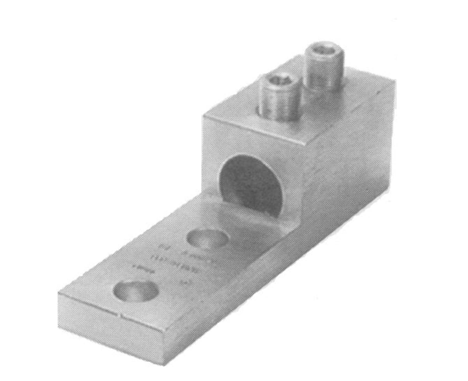
2.Terminal lug to carry full continuous current rating of conductor
3.NEMA bolt hole spacing is required on all connectors. Compression connectors must be long barrel type, similar to TID Stock Number U-6220-XXX.
4.On 3 phase, 400 amp and larger panel, terminal lugs shall be suitable compression type or 2 set screw type on conductor end. The lugs must have a minimum 2 bolt connection on the panel spades. See figures 1 and 2.
5.Before installation TID underground inspector must approve lugs and crimping die.
SHEET OF DWG. NO. PAGE CONSTRUCTION STANDARDS SERVICE WIRE SIZE UNDERGROUND 34701 M 2 2
Figure 1
Compression Type Connector
Figure 2
Set Screw Type Connector
Transformer Pad
General wire phasing. See following pages for specific applications based on panel size, number of conduits and cable size.
For special service locations, other arrangements may be acceptable. Please consult ENGINEERING first.
Neutral conductor(s) must be installed in left most conduit(s)
High Voltage Conduits
Low Voltage Conduits (number determined by service size)
PRIMARY COMPARTMENT SECONDARY COMPARTMENT SHEET OF DWG. NO. PAGE REVDESCRIPTION INIT CHK RV'DRV'D APP DATE RV'D CONSTRUCTION STANDARDS UNDERGROUND COMMERCIAL SERVICE INSTALLATION GUIDELINES 34750 F 1 4 BADD 3RD CONDUIT TO 600 & 800 AMP PANEL SDC MSG EDJ03-2009 CUPDATE TITLEBLOCK ELJ MSG09-2016
Figure 1
General Wire Phasing
DCHANGED FROM CONDUCTOR TO CONDUIT ON PG. 3 SSG EDJ06-2019 NOTES: 1.Bell ends must be installed on each conduit. EADDED NOTE 1 SSG AJB DNP MSG03-2021 FREVISED CONDUITS ADL SSG01-2024
NOTES:
400 & 600AMP
3 - 4" CONDUITS
2 CONDUCTORS PER PHASE
1 NEUTRAL CONDUCTOR
2 NEUTRAL CONDUCTORS HIGH
800, 1000, 1200, & 1400 AMP
3 - 5" CONDUITS
3 CONDUCTORS PER PHASE
1 NEUTRAL CONDUCTOR
1600 and 1800 Amps
1.Bell ends must be installed on each conduit.
2.2023 NEC Table C.11 referenced for conduit fill C PHASE
1600 & 1800 AMP
4-5" CONDUITS
4 CONDUCTORS PER PHASE
SHEET OF DWG. NO. PAGE CONSTRUCTION STANDARDS UNDERGROUND COMMERCIAL SERVICE INSTALLATION GUIDELINES 34750 F 2 4
HIGH VOLTAGE CONDUITS
VOLTAGE CONDUITS A PHASE & NEUTRAL B PHASE
C PHASE
Figure 2
400, 600, 800, 1000, 1200 and 1400 Amps
Figure 3
NEUTRAL A PHASE B PHASE
NOTES:
1.Bell
2.2023
2000 & 2500 AMP
6 - 5" CONDUITS
5 CONDUCTORS PER PHASE
2 Neutral Conductors
3000 AMP
6 - 5" CONDUITS
6 CONDUCTORS PER PHASE
2 NEUTRAL CONDUCTORS
SHEET OF DWG. NO. PAGE CONSTRUCTION STANDARDS UNDERGROUND COMMERCIAL SERVICE INSTALLATION GUIDELINES 34750 F 3 4
Figure 4
2000 ,2500, and 3000 Amps
ends must be installed on each conduit.
NEC Table C.11 referenced for conduit fill
HIGH VOLTAGE CONDUITS C PHASE B PHASE A PHASE AND NEUTRAL
Feed Conduit (from Transformer or Adjacent Box) to Occupy the Center Position
Secondary Conduit(s)
Service Conduit(s)
SHEET OF DWG. NO.PAGE REVDESCRIPTIONINITCHKRV'DRV'DAPPDATE RV'D
STANDARDS SERVICE BOX INSTALLATION 34805I 12 HUPDATED TITLEBLOCK, TABLES, NOTESELJMSG09-2016 ESPECIFY FEED CONDUIT IN CENTER POSITIONSDCGKTMSGDBMKJOBLL03-2007 FRELABEL CONDUITSSDCBSKJODBMGKTBLL09-2007
TITLE BLOCK, ADDED MATERIAL STDJRSMSGJSAMLHSDPEDJ06-2013
CONSTRUCTION
GREPLACE
Plan
Figure 1
View
Profile
1 2
Secondary Conduit(s) F B E C D
TABLE 3SSGDNHDPMNMSG06-2021
Figure 2
View
Service Conduit(s)
IADDED
TID Equipment Front SidesBack
Service Box333
Notes:
A.The soil under the service box shall be compacted to no less than 95% relative compaction.
B.Leave approximately 3 feet of pull rope extended past conduit.
C.Leave approximately 4 feet of service conductor extended past conduit.
D.Insert conduit 2 inches inside service box.
E.All conduits are to be located against the same end of the service box.
F.The box lid must be labeled "ELECTRIC".
G.See Construction Standard 35201 for size and quantity of conduits required.
SHEET OF DWG. NO.PAGE CONSTRUCTION STANDARDS SERVICE BOX INSTALLATION 34805I 22 Item Stock Number QtyDescription Material STD 1O-13XX-XXX1 Service Box (size as required) 2022 2 U-8200-004 As Req'd 3 4" Pull Rope 2401
Resource Qty Hours Line Supervisor 1 1.0 Lineman 1 Line Truck1
Table 1Bill of Materials
Table 2Resources
Table 3Clearances (Min. in Ft)
Conduit
Service Entrance Panel
Alternate Location. Use 30 Degree (max)
Sweeping Ells or Form Conduit to Fit, but Keep Angles 30 Degrees or Less (See Note 2)
Service Entrance Elbow to be Pointed Towards TID Electric Box
Conduit
Service Entrance Panel
Preferred Location
Service Entrance Elbow to be Pointed Towards TID Electric Box
Notes:
1.Service entrance equipment will conform to applicable sections of the Electric Utility Service Equipment Requirements Committee (EUSERC) Standards.
2.All PVC conduits must be adequately glued and set prior to installation of conductors. Only sweeping types of bends are acceptable. Conduit that is deformed due to heating or over stressing during installation will not be acceptable.
3.Meters will be furnished and set by TID after the installation has been approved by the governing inspection agency.
4.The service entrance panel shall be mounted so that the center of the meter will be at a height between a minimum of 48 inches and a maximum of 75 inches above finished grade.
5.Grounding shall be in accordance with the National Electric Code (NEC) and local codes. TID may require that the grounding conductor be installed in EMT or cable armor to protect the conductor from mechanical damage. Use approved cast ground clamp.
6.Conduit size and schedule per TID Construction Standard 35201.
CONSTRUCTION STANDARDS
SHEET OF DWG. NO.PAGE REVDESCRIPTIONINITCHKRV'DRV'DAPPDATE RV'D
MINIMUM REQUIREMENTS FOR RESIDENTIAL SERVICES USING UNDERGROUND CONSTRUCTION 34810J 11 JUPDATED TITLEBLOCKELJMSG09-2016 FCORRECTED METER HEIGHTBBRWCRWBLBGRA03-1994 GREDRAWN IN AUTOCADSDCPJOKJOLBGBLL04-2003 HCLARIFY GROUNDING REQUIREMENTSSDCKJODMGKTBLL02-2006 IREPLACE TITLE BLOCKJRSMSGJSAMLHSDPEDJ06-2013
Figure 1
Typical Surface Mount
Figure 2
Typical Flush Mount
36"
Finished Grade Finished Grade
36"
2.3.StreetLights
Streetlightsarenormallyservedfromtheserviceboxoftransformerasdesignatedby theDistrict. Streetlightvoltagesare120voltsforresidentialsubdivisionsandeither 120or277volts(dependingonavailability)forcommercialorindustrialtracts.
ThedeveloperorcontractorisresponsibleforplacingtheTIDidentificationnumberson cityownedstreetlightsinaccordancewiththedrawingshowninthissection. The numbertagsmustbeobtainedfromCustomerServiceattheDistrict'smainoffice. A copyoftheletterandlocationmapfromthecity/countytotheDistrictrequestinglight servicewillberequiredbeforeanynumbertagsareissued. TheDistrictwillnotprovide electricservicetoalightifitisnotnumberedorisnumberedincorrectly.
72
1.Street and area lights shall be labeled with their assigned Type (T3 or T5) and fixture wattage.
2.The TID LED type and wattage shall be placed on the bottom of the light such that it is visible from ground level.
3.The numbers affixed to the street and area light shall conform to TID Stock Number O-7805-00X.
CONSTRUCTION STANDARDS
SHEET OF DWG. NO.PAGE REVDESCRIPTIONINITCHKRV'DRV'DAPPDATE RV'D
LABELING FOR STREET AND AREA LIGHTS 24060C 11
LIGHT NUMBERING:
STREET AND AREA
--INITIAL ISSUEBBETERWBRCMAKH AREDRAWN IN AUTOCADSDCPJOKJOBLL04-2003 BUPDATE TITLEBLOCKELJMSG09-2016
T3 or T5
Figure 1
Bottom View
Figure 2
CUPDATED FORLED STREET AND AREA LIGHT NUMBERSSGABDMHEDJ03-2019
Side View
T3
or T5 XXW XXW
ALL STREET LIGHT CONDUCTORS
CONTAINED WITHIN THIS AREA
(PROPERTY
NOTES:
1.All conduit to be 1'' schedule 40 PVC. All 90° bends to be preformed schedule 40 elbows with a standard radius sweep. All conduits for street lights to be placed on the far right side of the transformer pad (where applicable).
2.Street light conduits will be placed in the P.U.E. in the first foot behind the property line.
3.All conductors to be sized per code with the appropriate copper wire. Neutral shall be marked per code.
4.Applicant shall guarantee no less than 0.95 relative compaction for all disturbed soils.
CONSTRUCTION STANDARDS
SHEET OF DWG. NO.PAGE REVDESCRIPTIONINITCHKRV'DRV'DAPPDATE RV'D
UNDERGROUND STREET LIGHT SERVICE CONDUIT DETAILS 34030D 11 GROUND ROD
STREET CONDUITS HIGH VOLTAGE LIGHT LOW VOLTAGE CONDUITS
LIGHT CONDUITS SIDEWALK
CONDUIT(S)
STREET
STANDARD LIGHT GRADE FINAL BELOW -0'' 1' +4'' 24'' ± 1'' A OR N-9 BOX SECONDARY BOX A
STREET SIDEWALK LP 10' PUE WIRE TAIL MIN. 3FT
30"
STAKE)
17" X
BOX LOCATED WITHIN 5 FEET OF SECONDARY SIDE OF TRANSFORMER
AREDRAWNRWBRAAKH10-1987 BREDRAWN IN AUTOCADSDCKJOBLL04-2003 CUPDATED TITLEBLOCKELJMSG09-2016
Figure 1
Overhead Layout
Figure 2
Underground Cross Section A-A
Figure 3
CCHNAGED SECONDARY BOX SIZESSGDHABEDJ04-2020
Transformer Pad Detail
Section III: Meter Requirements
3.1.WhoProvidesMeters?
Allmetersandmeteringtransformerswillbeprovided,installed,ownedandmaintained byTID.
3.2.CustomerMeteringEquipmentOwnershipand Responsibilities
Theapplicantwillprovide,install,ownandmaintainallmetersockets,metersocket enclosures,meteringtransformercabinetsandswitchboardservicesectionsofthetype approvedbyTID.
3.3.WhenAreMetersInstalled?
MeterswillbeinstalledandenergizedbyTIDafterthecustomer'smeteringequipment hasbeenproperlyinstalledandafteraninspectionclearancehasbeengivenbythe appropriateelectricalinspectionauthority. Theinspectiontagmustbepresentbefore theservicemanarrivestosetthemeter.
3.4.MeterAccess
Allmeteringfacilitiesshallbeinstalledinlocationswhichwillbereadilyaccessibleatall timesforinspection,readingandtesting. Bydefinition,readilyaccessiblemeans capableofbeingreachedquickly,foroperation,replacement,orinspections,without requiringthosetowhomreadyaccessisnecessarytoclimboverorremoveobstaclesor toresorttoportableladders,chairs,etc.
3.5.MeterHeight
Therequirementsformeterheight,whichistheverticaldistancebetweenthe centerlineofthemeterandthegroundorstandingsurface,shallbeasfollows:
48"minimum-75"maximumforsinglemeterresidential&meterpedestals
75
36"minimum–75”maximumallowedforcommercialmeterclustersin self-supporting,rain-tightcabinets
3.6.MeterWorkingSpace
Workingspaceinfrontofthemeterpermitsaccesstothemeteringinstallationand providesworkingsafetyforpersonnel. Aworkingspaceentirelyonthepropertyofthe customerisrequiredinfrontofallmetersexceptforbuildingsconstructedonzerolot lines.
Theworkingspaceistobekeptclearandunobstructedandshallnotbeusedfor storage.
Whenmetersormeteringequipmentareplacedincabinetenclosures,theclear workingspaceshallextendfromtheouterfaceofthecabinet.
Theheightoftheclearworkingspaceshallbe78inchesminimumfromthestanding surface.
Thewidthoftheclearworkingspaceshallbe36inchesminimumforasinglemeter installationandshallextendtheadditionalwidthnecessaryforaccesstothetotal numberofmeteringpanels. Thecenterlineofanymetershallnotbelessthan18 inchesfromanyadjacentsidewallorotherprotrudingobstruction.
Thedepthoftheclearworkingspaceshallbe36inchesminimumforservicesrated150 voltsorlesstoground. Whentheserviceisratedinexcessof150voltstoground,the depthshallbeasrequiredbyapplicableelectricalcodesorasdictatedbythephysical designandarrangementofthemeteringcubicles.
3.7.Barricades
Permanentbarricadesshallberequiredtomaintaintheclearancesformeterlocations wheretheworkingspaceisexposedtovehiclesorhazardousconditions. Asexamples, suitablebarricadesmayinclude:(1)concrete-filledsteelpipes,3inchesindiameteror greater,securelysetinanadequateconcretepourforsupport,orsleevemountedwith thesleevessetinconcrete,whichmaybeusedforavehiclebarricade,or(2)heavy wiremeshfencing,securelysupported,whichmaybeusedasabarricade. Curbsdo notconstitutebarriers.
76
3.8.MeterLocations–GeneralConditions
Inorderthatthemostsatisfactorymeterlocationmaybedeterminedandadequate spaceprovided,TIDshouldbeconsultedwhilethebuildingorresidenceisinthe preliminaryplanningstage. Installationofadditionalfacilitiesatthecustomer'sexpense orfuturerelocationsathisexpensemaybepreventedbyearlyconsultationwithTID. Thefollowingbasiclocationrequirementsshallapplyinallcases:
1. AlllocationsformetersandmeteringequipmentaresubjecttoTIDapproval.
2. Metersshallbeaccessible(withduallockingdevicesifnecessary)duringand afterlandscapingorotherbuildingconstruction. Nometershallbeenclosedby anyfencingwithoutpermissionfromanauthorizedTIDrepresentative.
3. Metersandmeteringequipmentinstalledonorrecessedintheexternalsurface ofanybuildingshallhaveaclearworkingandstandingspaceentirelyonthe propertyofthecustomerserved. Anyexceptionfromthisrequirementmustbe approvedbyTID.
4. Forthemeterdistancefromthetransformer,refertoconstructionstandard 50510.
Thefollowingareunacceptablelocationsforelectricmeters:
1. Inanylocationthatishazardoustoequipmentorpersonsorunsuitable forentry,suchas:
a. anyelevatorshaft.
b. anydoorwayorhatchway.
c. directlyoveranystairway,ramporsteps.
d. anyareaaccessibleonlythroughatrap-door,hatchway,orby meansofaladder.
e. Anyareawherepersonnelmaycontactexposedhighvoltage conductorsorequipmentinmotion.
2. Inanyplacewherevibration,moisture,excessivetemperature,fumes, ordustmaydamagethemeterorinterferewithitsoperation.
3. Withinorrequiringaccessthroughanybath,shower,powderortoilet room.
4. Onanyportionofabuildingwherelaterlandscaping,fencingorother buildingconstructionwillmakethemeterinaccessible.
5. Withinanyenclosedareathatcontainsorwillcontaingasmeters.
77
6. Metersandmeteringequipmentshallnotbeinstalledwithinanylocked facilityinwhichTIDwouldbedeniedaccessatanytimeoftheday.
7. Indoors.
8. Outdoormetersshallnotbeinstalledwheretheywillinterferewith traffic,sidewalks,driveways,orwheretheywillobstructtheopeningof doorsorwindows,orinanylocationwhichmaybeconsidered hazardousorcausedamagetothemeteringequipment.
3.9 . RemoteMetering
Remotemeteringisacceptableininstanceswhereanexternalpanelorswitchboardis notutilized.
Thefollowingspecialarrangementsarerequired:
1. ApplicantshallprovideanapprovedCTmountingcabinetthatcomplies withthepreviousparagraph"MeterLocations-GeneralConditions."
2. 11/4"steelconduitbetweentheCTcabinetandmetersocket.
3. Meterwillbelocatedwithin50conductorfeetofCTcabinet
4. Forspecialmeterdistancerequirementsrefertoconstructionstandard 50510.
5. Junctionboxesarepermittedonlyiftheycanbesealed.
6. Couplingsmusthavesealscrews.
3.10. PlanningandGroupingofAdditionalMeters
Occasionallythereisneedtolocateandinstalladditionalserviceandmetering equipmentaftertheoriginallyplannedelectricserviceforabuildingisinstalledand energized. Wherepossible,additionalmetersshouldbegroupedwiththoseelectric metersalreadyinservice.
3.11. TwoorMoreHousesonOneLot
Ifmorethantwodwellingsorbuildingsarelocatedonthesamelot,consultTIDto determineacceptablemeterlocationsbeforeproceedingwiththewiringofthe buildings.
Forasingle-familydwellinglocatedbehindanotherdwellingorcommercial establishmentonaninside(non-corner)lotnotsubjecttofurthersubdivision,the metersshallbelocatedadjacenttoeachotheratthebuildingclosesttothedistribution
78
linefromwhichservicewillbesupplied. Allwiringbeyondthemeterswillbeatthe customer'sexpense.
Formulti-dwellingbuildingsconstructedontherearofnon-commerciallots,ifpractical, andatthecustomer'srequest,TIDwillinstallseparateservicefacilitiestotherear building. Themetersfortherearbuildingshallbegroupedtogetheratasuitable locationattherearbuilding.
3.12. MeterOccupancyIdentification
Wheremetersaregroupedatacommonlocation,suchasfortwoormorehousesona lotorforamultipleoccupancybuilding,eitherresidentialornon-residential,eachmeter positionanditsdirectlyidentifiableservicedisconnectshallbeclearlyandpermanently markedbythebuildingownerorhisrepresentativetoindicatetheoccupancyserved (PerN.E.C.230-72a). Examplesofpermanentmarkingshallbeengravedplateattached byscrews,rivets,ortwo-partepoxy.. Clearidentificationmeansalegibleapartmentor streetnumber. Thestorenamemaybeincludedbutdoesnotconstituteaclear designationinitself. Apartmentorsuitenumbersmustbeonoradjacenttothedoorof eachunit.
3.13. SealingofMetersandMeteringEquipment
Allmetersandenclosuresformeters,meteringequipmentandserviceentrance equipmentonthelinesideofthemeterwillbesealedbyTID. TheTIDsealshallnot bebrokenexceptbyanauthorizedrepresentativeofTID. Nopersonispermittedto tamper,remove,replace,orinanywayinterferewithameteroritsconnectionsas placedbyTID.
3.14. MeterSocketBypassDevices
Automaticbypassorcircuitclosingdevicesthatclosewhenthemeterisremovedfrom thesocketshallnotbeused.
Manualcircuitclosingdevicesarerequiredonallserviceentranceequipmentexceeding 30ampsnameplateratingexcept,domestic,signboardsandtemporaryservice. Service entranceequipmentmustbecontinuouslyratedperU/L414.
3.15. Self-containedMeteringDefined
Aself-containedmeteriscapableofcarryingthetotalcurrentatthevoltageofthe electricservicesuppliedtothecustomer. Socketsforself-containedmetersaredirectly
79
connectedtothecustomer'sserviceentranceconductors,andthemeterisinsertedinto thesocket. Metersocketsareavailablewithnominalratingsof100or200amperes. . ContactTIDfordetailsonsingle-phase,400Ampservice.
3.16. Transformer-ratedMeteringDefined
Whentheelectricserviceneedsoftheapplicantexceedtheampacityorvoltage limitationsofaself-containedmeter,meteringtransformers,whichconnectdirectlyto thecustomer'sserviceentranceconductors,mustbeused. Atransformer-ratedmeter isthenconnectedtothemeteringtransformerstomeasuretheenergydeliveredtothe customer. Themeteringtransformersandthetransformer-ratedmeter(s)arefurnished andinstalledbyTID.
3.17. EUSERC
ElectricUtilityServiceEquipmentRequirementsCommittee(EUSERC)isanorganization whosepurposeistopromoteuniformelectricservicerequirementsamongtheutilities. TIDisamemberofandsupportsEUSERC. Assuch,whenanapplicantwishesservice withintheDistrictserviceareaandtheequipmentchosenmeetsEUSERC,itis understood,withsomespecificexceptions,thatTIDwillprovidepowertothe equipment. CheckwiththeDistrictfordetails.
3.18. Switchboards
Switchboardsareconsideredaspecialtyitemformeteringequipment. TIDrequirestwo setsofapprovaldrawingsofsuchequipment. IfTIDtakesexceptiontotheequipment, theapplicantwillbenotifiedofthechangesrequired. Shouldtheapplicantrequest serviceandtheequipmentisnotacceptable,servicewillnotbeconnected. Havethe equipmentcheckedandapprovedpriortorequestingservice. Itwillsavetimeand headachesforeveryoneinvolved.
Theswitchboardmust,ataminimum,meetEUSERCrequirements. Aswitchboard servicesectionhasahingedmeterpanellocatedinfrontoftheinstrumenttransformer compartment. HingedmeterpanelsmusthaveEUSERChandlesandopenaminimum of90° withmetersandtestswitchesmounted. Hingedmeterpanelsmustbesealable.
Forspecialmeterdistancerequirements,refertoconstructionstandard50510
80
Notes:
1.The electrical panel shall be installed within the first five feet of the corner of the structure.
2.The electrical panel shall be installed near the corner of the structure closest to the utility trench.
SHEET OF DWG. NO.PAGE REVDESCRIPTIONINITCHKRV'DRV'DAPPDATE RV'D
STANDARDS UNDERGROUND RESIDENTIAL SERVICE PANEL LOCATION 34815B 11 --INITIAL ISSUESDCKJOBLL04-2003
CONSTRUCTION
3.The electrical panel shall be adjacent to other utilities.
4.The electrical panel shall be on the street side of any fences.
See Note 2
Surface mount
AREPLACE TITLE BLOCKJRSMSGJSAMLHSDPEDJ06-2013
Flush mount
Figure 1
BUPDATE TITLE BLOCKELJMSG09-2016
Underground Residential Service Panel Location
Pre-Fabricated Metering Pedestal
Meter & Breaker Assembly
Treated or Redwood
Timber per California
Administrative Code, Title 25.
Meter & Breaker Assembly
Notes:
75" max. 48" min.
Conduit Size per TID Standards
Customer Conduit
Approved Grounding Clamp Must Be Accessible. Extend Metallic Tubing or Cable Armor to Ground Rod to Protect Ground Wire From Mechanical Damage.
Conduit Size per TID Standards
Customer Conduit
Approved Grounding Clamp Must Be Accessible. Extend Metallic Tubing or Cable Armor to Ground Rod to Protect Ground Wire From Mechanical Damage.
36" +/3"
Pre-Fabricated
Ground Conductor per Code
Ground Conductor per Code
Treated or Redwood Timber Metering Pedestal
1.Service entrance equipment will conform to applicable sections of the Electric Utility Service Equipment Requirements Committee (EUSERC) Standards.
2.Customer shall supply panel with bus bar lugs where one set of lugs feeds all meters. Lug size and quantity will be specified by the District.
3.Meters will be furnished and set by TID after the installation has been approved by the governing inspection agency.
4.No service will be run under existing or future concrete areas.
5.All PVC conduits must be adequately glued and set prior to installation of conductors. Only sweeping type bends are acceptable.
6.See Construction Standard 30571 for trench configurations. Finished Grade
CCOMBINED WITH
REVDESCRIPTIONINITCHKRV'DRV'DAPPDATE SHEET OF DWG. NO.PAGE RV'D
MINIMUM REQUIREMENTS FOR SINGLE MOBILE HOME METERING USING UNDERGROUND CONSTRUCTION 34820F 11 FUPDATE TITLEBLOCKELJMSG09-2016
NOTESSPRWBRCMRAAKH10-1989
CONSTRUCTION STANDARDS
BCHANGED
BOOKBBETERWBLBGRA06-1993
IN AUTOCADSDCPJOKJOBLL04-2003 EREPLACE TITLE BLOCKJRSMSGJSAMLHSDPEDJ06-2013
CUSTOMER
DREDRAWN
Figure 1
Metering Pedestal
Figure 2
75" max.
36" +/3"
48" min.
Redwood Hangers
Configuration May Vary
Meter and Breaker Assembly for Underground Feed
Redwood Posts per California Administrative Code, Title 25 Conduits from Panel
Service Entrance Conduit and Conductors to Service Pedestal, Size per TID Standards
Ground Conductor per Code
Approved Grounding Clamp, Must be Accessible. Extend Metallic Tubing or Cable Armor to Ground Rod to Protect Wire from Mechanical Damage.
Finished Grade
Ground Rod
Figure 1
Multiple Mobile Home Metering
Using Underground Construction
Notes:
1.Service entrance equipment will conform to applicable sections of the Electric Utility Service Equipment Requirements Committee (EUSERC) Standards.
2.Customer shall supply panel and bus bar lugs where one set of lugs feeds all meters. Lug size and quantity will be specified by the District.
3.Meters will be furnished and set by TID after the installation has been approved by the governing inspection agency.
4.No service will be run under existing or future concrete areas.
5.All PVC conduits must be adequately glued and set prior to installation of conductors. Only sweeping type bends are acceptable.
6.See Construction Standard 30571 for trench configurations.
BCHANGED
CCOMBINED WITH
REVDESCRIPTIONINITCHKRV'DRV'DAPPDATE SHEET OF DWG. NO.PAGE RV'D
MINIMUM REQUIREMENTS FOR MULTIPLE MOBILE HOME METERING USING UNDERGROUND CONSTRUCTION 34830F 11 FUPDATE TITLEBLOCKELJMSG09-2016
CONSTRUCTION STANDARDS
NOTESSPRWBRCMRAAKH10-1989
BOOKBBETERWBLBGRA06-1993
IN AUTOCADSDCPJOKJOBLL04-2003 EREPLACE TITLE BLOCKJRSMSGJSAMLHSDPEDJ06-2013
CUSTOMER
DREDRAWN
Configurations May Vary
Main Disconnect
48" min. 75" max. See Note 6
Ground Conductor per Code
Finished Grade
Approved Grounding Clamp Must be Accessible. Extend Metallic Tubing or Cable Armor to Ground Rod to Protect Ground Wire from Mechanical Damage.
Customer Service Conduit if Required
Figure 1
Multiple Metering
Using Underground Construction
Conduit Size per TID Requirements
36" +/3"
Notes:
1.Service entrance equipment will conform to applicable sections of the Electric Utility Service Equipment Requirements Committee (EUSERC) Standards.
2.Customer shall supply panel with bus bar lugs where one set of lugs feeds all meters. Lug size and quantity will be specified by the District.
3.Meters will be furnished and set by TID after the installation has been approved by the governing inspection agency.
4.No service will be run under existing or future concrete areas.
5.All PVC conduits must be adequately glued and set prior to installation of conductors. Only sweeping type bends are acceptable.
6.Minimum meter height may be reduced to 36" when utilizing enclosed switchboards.
7.See Construction Standard 30571 for trench configurations.
CCOMBINED WITH CUSTOMER
DREDRAWN
CONSTRUCTION STANDARDS
REVDESCRIPTIONINITCHKRV'DRV'DAPPDATE SHEET OF DWG. NO.PAGE RV'D
MINIMUM REQUIREMENTS FOR MULTIPLE METERING USING UNDERGROUND CONSTRUCTION 34840F 11 FUPDATE TITLEBLOCKELJMSG09/28/2016
CHANGESPRWBRCMRAAKH10-1989
BDIMENSION
BOOKBBETERWBLBGRA06-1993
IN AUTOCAD
TITLE BLOCKJRSMSGJSAMLHSDPEDJ06-2013
EREPLACE
*Potential fuses (TID Stock Number U-7115-000) are required for padmount and indoor metering enclosures. No potential fuses shall be installed on overhead/pole metering installations.
This standard is for all new primary metering services.
All new installations shall use 3 P.T.'s and 3 C.T.'s.
Page 2 shows metering wiring for new installations.
Page 3 shows EUSERC panel requirements.
Page 5 shows existing metering installations using 2 P.T.'s & 2 C.T.'s and shall be for maintenance only.
POTENTIAL FUSES * 3 ∅ LOAD SOURCE 12KV, 3 WIRE SHEET OF DWG. NO.PAGE REVDESCRIPTIONINITCHKRV'DRV'DAPPDATE RV'D CONSTRUCTION STANDARDS METER WIRING 12 KV PRIMARY METERING 51081E 15
BCLARIFY POLARITY MARKINGSSPETELBGRWBRA01-1992 SPECIFY SOLID STATE METERBBRCDJTBLL06-1995 CCOMBINE STD 51080, 51081, 51082, 51085, DCHANGE TO 3 ELEMENT METERINGSDCDBMTWCGKTBLL07-2004 EUPDATE TITLEBLOCK AND STOCK NUMBERSELJMSG09-2016
13
Meters installed after June 1995 are to be solid state multi-function meters with demand, mass memory, and modem. Meters installed before June 1995 might have various options depending on installation.
TEST SWITCH
JAW METER FORM 9S SHEET OF DWG. NO.PAGE CONSTRUCTION STANDARDS METER WIRING
KV PRIMARY METERING 51081E 25
12
Meter CT Stock NumberCT RatioPT Stock Number PT Ratio Test Switch Stock No. Itron Sentinel Level 2 or Elster A3 or Elster RL W-1700-000200:5 W-2300-00060:1W3300-000 W-1710-000400:5 W-1720-000600:5
W-1730-000800:5
Table 1Material List


NOTES:
This drawing conforms to EUSERC dwg 401.
1. P.T. disconnect per EUSERC dwg. 400 III A.
2. Meter panel per EUSERC dwg. 403.
3. P.T.'s per EUSERC dwg. 410.
4. P.T. mounting per EUSERC dwg. 402.
5. C.T.'s per EUSERC dwg. 408.
6. Meter may be remoted to outside wall. See developer info booklet.

SHEET OF DWG. NO.PAGE CONSTRUCTION STANDARDS METER WIRING 12 KV PRIMARY METERING 51081E 35
2 1 3 4 2 5 4
Customer Requirements:
1.Customers must request and receive approval of 12 kV service in advance and prior to customer's design completion and switchboard purchase. TID shall review and approve service request, location switchboard drawings, and other service parameters. Customer must comply with the provisions of this standard, TID's Developer Information Book, TID rules, rates tariffs and standards, and applicable provisions of the NEC, OSHA requirements, and other applicable codes, regulations and laws.
2.All 12 kV service will be 12,000 Volt nominal 3-wire service.
3.Customers shall provide a breaker as the main protective device (fuses are not acceptable). Main protective device must have adjustable phase and ground trip settings. Customer shall provide settings, protective device details, and time-current curves to TID staff for approval. Phase and ground overcurrent coordination with TID's source-side device is required (except for IT - see item 4 below).
4.Instantaneous Overreach. TID will provide notice of, upon request, the available fault current contribution form TID's system at the point of interconnection. For fault currents above approximately 3,000 amps, it may not be possible to achieve coordination with the customer's relay/breaker protection due to TID's instantaneous trip setting. Customer's protective device must go to lock out (i.e. no reclosing is allowed) until Customer has received approval from TID's Power Control Center.
5.Any on-site generation must comply with separate standards and requirements (please contact TID if on-site generations is considered).
6.TID will specify the cable and conduit from the 12 kV switchgear to the TID facility interconnection (TID to install and terminate cable only - see specific detailed design for the project). If the unprotected length of other factors associated with the facility interconnection result in a substantial exposure (in TID staff's opinion), TID will notify the customer and other measures may be taken to reduce the exposure, including relocation of the switchgear or interconnection point or installation of a TID line recloser (at Customer's cost).
7.Customer shall be obligated to perform industry standard tests by qualified personnel on the main protective device with the approved settings, in TID's presence, and submit test reports to TID. Please allow 1 week notice to TID staff for scheduling attendance.
8.Customer is expected to maintain and keep in good working order the 12 kV switchgear and main protective device. Any main protective device setting changes must be approved in advance by TID. TID may request attendance at the time of setting change and/or that test sheets are provided for TID approval.
SHEET OF DWG. NO.PAGE CONSTRUCTION STANDARDS METER WIRING 12 KV PRIMARY METERING 51081E 45
8 JAW METER FORM 5S
KYZ
PIGTAIL
SEE SHEET 3 IF NEEDED
SEE STANDARD INSTALLATION FOR RECORDER
51084 FOR INTERFACE CUSTOMER
AC POWER IF NEEDED
(SEE SHEET 3)
TEST SWITCH
Meters installed after June 1995 are to be solid state multi-function meters with demand, mass memory, and modem. Meters installed before June 1995 might have various options depending on installation.
KTK 1.0
A
OF DWG. NO.PAGE
STANDARDS
WIRING
KV PRIMARY METERING 51081E 55 * 2 ELEMENT - FIELD MAINTENANCE ONLY Meter CT Stock Number Service Amps PT Stock Number PT Ratio Test Switch Stock No. Itron Sentinel Level 2 or Elster A3 or Elster RL W-1600-000100 W-2300-00060:1W3300-000 W-1610-000200 W-1620-000400
SHEET
CONSTRUCTION
METER
12
Table 2Material List
*Potentialfuses(TIDStockNumberU-7115-000)arerequiredforpadmountandindoormetering enclosures.Nopotentialfusesshallbeinstalledonoverhead/polemeteringinstallations.
Thisstandardisforallnewprimarymeteringservices.
Allnewinstallationsshalluse3P.T.'sand3C.T.'s.
Page2showsmeteringwiringfornewinstallations.
Page3showsEUSERCpanelrequirements.
TURLOCKIRRIGATIONDISTRICT
POTENTIALFUSES* 3∅ LOAD SOURCE BK R O Y 12KV,3WIRE SHEET OF DWG.NO. PAGE
REVDESCRIPTION INITCHKRV'DRV'DRV'DAPPDATE CONSTRUCTIONSTANDARDS METERWIRING 12KVGENERATIONMETERING 51082A 14 BL
BR AINITIALISSUE ADLMACDNP SSG10/2022 WH/GN WH/GN
FORM9S
YBK YBK OBL R BLWH/GNO RBR TEST SWITCH
13JAWMETER
SHEET OF DWG.NO. PAGE CONSTRUCTIONSTANDARDS METERWIRING 12KVGENERATIONMETERING 51082A 24 BR Meter CTStockNumberCTRatioPTStockNumberPTRatioTestSwitchStockNo. SEL735 W-1700-000 200:5 W-2300-000 60:1 W3300-000 W-1710-000 400:5 W-1720-000 600:5 W-1730-000 800:5
WH/GN WH/GNWH/GN WH/GNWH/GN
Table1MaterialList


NOTES:
AllpanelsmustconformtoEUSERCsection400dwg. 401.
1.P.T.disconnectperEUSERCsection400IIIA.
2.MeterpanelperEUSERCdwg.408.
3.P.T.'sperEUSERCdwg.404.
4.P.T.mountingperEUSERCdwg.407.
5.C.T.'sperEUSERCdwg.407.
6.Metermayberemotedtooutsidewall.See developerinfobooklet.

SHEET OF DWG.NO. PAGE CONSTRUCTIONSTANDARDS METERWIRING 12KVGENERATIONMETERING 51082A 34
2 1 3 4 2 5 4
CustomerRequirements:
1.Customersmustrequestandreceiveapprovalof12kVserviceinadvanceandpriortocustomer'sdesign completionandswitchboardpurchase.TIDshallreviewandapproveservicerequest,locationswitchboard drawings,andotherserviceparameters.Customermustcomplywiththeprovisionsofthisstandard,TID's DeveloperInformationBook,TIDrules,ratestariffsandstandards,andapplicableprovisionsoftheNEC, OSHArequirements,andotherapplicablecodes,regulationsandlaws.
2.All12kVservicewillbe12,000Voltnominal3-wireservice.
3.Customersshallprovideabreakerasthemainprotectivedevice(fusesarenotacceptable).Mainprotective devicemusthaveadjustablephaseandgroundtripsettings.Customershallprovidesettings,protective devicedetails,andtime-currentcurvestoTIDstaffforapproval.Phaseandgroundovercurrent coordinationwithTID'ssource-sidedeviceisrequired(exceptforIT-seeitem4below).
4.InstantaneousOverreach.TIDwillprovidenoticeof,uponrequest,theavailablefaultcurrentcontribution formTID'ssystematthepointofinterconnection.Forfaultcurrentsaboveapproximately3,000amps,it maynotbepossibletoachievecoordinationwiththecustomer'srelay/breakerprotectionduetoTID's instantaneoustripsetting.Customer'sprotectivedevicemustgotolockout(i.e.noreclosingisallowed) untilCustomerhasreceivedapprovalfromTID'sPowerControlCenter.
5.Anyon-sitegenerationmustcomplywithseparatestandardsandrequirements(pleasecontactTIDif on-sitegenerationsisconsidered).
6.TIDwillspecifythecableandconduitfromthe12kVswitchgeartotheTIDfacilityinterconnection(TIDto installandterminatecableonly-seespecificdetaileddesignfortheproject).Iftheunprotectedlengthof otherfactorsassociatedwiththefacilityinterconnectionresultinasubstantialexposure(inTIDstaff's opinion),TIDwillnotifythecustomerandothermeasuresmaybetakentoreducetheexposure,including relocationoftheswitchgearorinterconnectionpointorinstallationofaTIDlinerecloser(atCustomer's cost).
7.Customershallbeobligatedtoperformindustrystandardtestsbyqualifiedpersonnelonthemain protectivedevicewiththeapprovedsettings,inTID'spresence,andsubmittestreportstoTID.Please allow1weeknoticetoTIDstaffforschedulingattendance.
8.Customerisexpectedtomaintainandkeepingoodworkingorderthe12kVswitchgearandmain protectivedevice.AnymainprotectivedevicesettingchangesmustbeapprovedinadvancebyTID.TID mayrequestattendanceatthetimeofsettingchangeand/orthattestsheetsareprovidedforTID approval.
SHEET OF DWG.NO. PAGE CONSTRUCTIONSTANDARDS METERWIRING 12KVPRIMARYMETERING 51082A 44
SectionIV: Materials
1. MaterialDrawings
2. DeveloperProvidedMaterialUsedinUndergroundConstruction
103
Notes:
1.Transformer Enclosure
2.Incidental Traffic Loading
3.Quick Release torsion assist Cover.
4.Inside Dimensions 3'
SHEET OF DWG.NO. PAGE REVDESCRIPTION INITCHKRV'DRV'DAPPDATE RV'D
STANDARDS SPECIFICATION TRANSFORMER VAULT 3' X 5' HORIZONTAL 2015B 1 3
MATERIAL
x 5' x 4'6" INITIALISSUE SDC BS DBM KJO GKT BLL 09-2007 AUPDATETITLEBLOCK ELJ MSG01-2017
Item TID Stock Number Type 1U-2179-001 Vault Assembly 2U-2179-002 Lid Assembly 3U-2179-0036" Extension
Figure 1
Table 1
BADDEDTORSIONASSISTCOVERSSGRBABEDJ01-2020
Vault Assembly
INSERT 1/2"
4 TYP
SPECIFICATION
TRANSFORMER VAULT
3' X 5'
SHEET OF DWG.NO. PAGE
MATERIAL STANDARDS
HORIZONTAL 2015B 2 3
n
3" 6 3/8"
4'-9 3/4" 4'-2 3/4"
24 EA
Knockouts 4 5/8" n
5"
1'-3 3/4"
8 7/16" 6 3/8"
Figure 2
Top View
Figure 3
Front View
Figure 4
Side View
4 - 7/8" Galvanized pull Irons
12"∅X 4" Sump
5'-0" 5'-8"
3'-0" 3-8"
∅1/2" Insert 4 Typ.
Lid Assembly
Name Plate Marked "T.I.D"
1 Ea. Name Plate marked "High Voltage"
2 Ea. Blanks Name Plates
Table 2
TRANSFORMER VAULT 3'
Incidental Traffic, Quick release
Torsion Assist Cover, slip Resistant
Aluminum Plates & Frame
SHEET OF DWG. NO.PAGE MATERIAL STANDARDS SPECIFICATION
x 5' HORIZONTAL 2015B 33
Item TID Stock Number Type Size 1U-2179-002 Lid and frame Assembly 36" X 60"
Figure 5
Hinged Spring Assist Chevron Grate With Locking Hasp
Drop In Style Name Plate Marked "T.I.D." & "HIGH VOLTAGE" 6"
2 ea. 1 1/2" dia. Holes
32 ea. 4 3/4" dia. Knock-Outs
4 ea. 24" Long P-4000 Struts
4ea. 9" dia. Knock-Outs
• Constructed of reinforced concrete
• Cover shall be marked "T.I.D." and "HIGH VOLTAGE"
• Designed for H-20 loading per ASTM C-857 and AASHT0
• Spring assist hinged lid Must be able to utilize 6" extension ring.
• Vault, lid, extension ring must be interchangeable between manufacturers.
• Top Weight=715 Lbs.
• Base Weight=3,720 Lbs.
MATERIAL STANDARDS
3'-6"
4'-0"3'-6" 4'-0" 3'-6" 4"
TID HIGHVOLTAGE
6'-6" 6'-2"
SHEET OF DWG. NO.PAGE REVDESCRIPTIONINITCHKRV'DRV'DAPPDATE RV'D
SPECIFICATION
3'-6"
6'-2" I.D. CONCRETE TRANSFORMER VAULT 2016C 12 AINITIAL ISSUEBBBBBLL03-1999 BREDRAWN IN AUTOCADJDMSGEDJ02-2011 CUPDATED TITLEBLOCKELJMSG01/2017
x
x
Figure 1
Vault Assembly
2ea. 1 1 2" DIA. HOLES
4ea. 24" long P-4000 struts
TID Stock no.
• U-2178-001 Vault
• U-2178-002 Complete lid assembly
• U-2178-003 6" Extension Ring
Figure 2
Interior View
Not To Scale
32 ea. 4 3 4" Knock-outs typically located
6" & 12" Risers for transformer
4ea. 9" Dia. knock-outs
2'-3" 6'-2"
1'-2"
9"
5'-0" 2'-10 1 2 " 6 1 2 " 2'-8" 6'-2" 2'-41 2 " 61 2 " 6" 1'-0" 7" 7" 3'-6" 4 1 2 " 6 1 2 " 10" 4 1 2 " 6 1 2 " 10" 3'-6" 41 2 " 61 2 " 10" 41 2 " 61 2 " 10" SHEET OF DWG. NO.PAGE MATERIAL STANDARDS SPECIFICATION
1'-0" 9" 1'-0"
3'-6" x 6'-2" I.D.
TRANSFORMER VAULT 2016C 22
3'-6" x
CONCRETE
• Pad shall be constructed of reinforced plastic mortar, concrete or approved equal.
• Material shall be ultra-violet radiation resistant.
• Pad finish shall include a non-skid surface.
• Provisions for mechanical lifting and leveling.
• Pads to be gray in color.
• Non-corrosive 1 5/8" channel shall be placed behind opening, running length of opening (reference dimension 'E').
• Pad thickness shall be a minimum of 4". Must be capable of holding designated weight capacity.
•
THREE PHASE
SHEET OF DWG. NO.PAGE REVDESCRIPTIONINITCHKRV'DRV'DAPPDATE RV'D
MATERIAL STANDARDS SPECIFICATION
TRANSFORMER
2017B 11 --INITIAL ISSUEETEBBJCLBGRA07-1994 AREDRAWN IN AUTOCADSDCPJOKJOLBGBLL04-2003 BUPDATED BORDER AND TABLEELJMSG09-2016
PAD
widths
+8" and -2". TID Stock Number ABCDEFG Weight Capacity U-2056-001 75" 80"50"16"1"10"11" 10,000 lb U-2056-005105"112"58"16"1"10"11" 20,000 lb
Lengths (A) and
(B) may vary by
Table 1Dimensions
CAST IN 1/2" INSERTS (TYP) SHEET OF DWG. NO.PAGE REVDESCRIPTIONINITCHKRV'DRV'DAPPDATE RV'D MATERIAL STANDARDS SPECIFICATION PADMOUNTED SWITCH STRUCTURE 2018E 12 EUPDATE TITLEBLOCKELJMSG09-2016 AREDRAWN IN AUTOCADSDCKJOBLL04-2003 BCORRECT COVER PLATE DIMENSIONSSDCBLL10-2004 CCHANGE DEPTH OF BOX TO 60"SDCBLL06-2005 DCHG KNOCKOUTS TO WIN STYLE, DEPTH 72"SDCDBMBLL06-2009 FOR COVER PLATE AND DETAILS SEE SHEET 2
Nominal Box Size (inside dimensions)
Length = 102"
Width = 54"
Depth = 72"
Constructed of reinforced concrete
Knock-outs shall be thin wall per drawing
Box shall have a solid bottom with sump provided as shown
Four pulling eyes are requred for installation of conductors
Box shall be per ASTM C857
Cover shall be bolted into position using Penta head bolts
Penta head bolts shall be 1 2 x 13 NC
Cover shall be skid resistant
Cover shall be plate steel per ASTM A829
SHEET OF DWG. NO.PAGE MATERIAL STANDARDS SPECIFICATION PADMOUNTED SWITCH STRUCTURE 2018E 22
T.I.D. Stock # U-2095-001
Single Phase Transformer Pad
Notes
A.Per Western underground committee guide 2.15 (latest Revision) flat single phase transformer pads.
B.Pad shall be constructed of reinforced plastic mortar (RPM) or approved equal.
C.Corrosion resistant channels or 1/ 2" holes shall be provided for equipment mounting purposes.
D.Approximate location shall be as indicated on drawing.
E.Material shall be Ultra-Violet radiation resistant.
F.Non-Skid surface. Thickness 4" - 5".
G.Provisions for mechanical lifting.
H.Pads to be gray in color. Material compressive strength shall >11000 PSI.
SHEET OF DWG. NO.PAGE REVDESCRIPTIONINITCHKRV'DRV'DAPPDATE RV'D
SPECIFICATION SINGLE PHASE TRANSFORMER PAD 2019C 12
MATERIAL STANDARDS
--INITIAL ISSUEETESPRWBRAAKH05-1990 AREDRAWN IN AUTOCADSDCPJOKJOBLL04-2003 BUPDATE TITLEBLOCKELJMSG09-2016 Equipment Mounting Hold Down A D 6" B C 11"
Item Stock Number ABCD 1U-2054-001 54" 48" 26"15"
Figure 1
CADDED TRANSFORMER PAD BOXSSGDPASLMSC05-2022
Table 1Transformer Pad Dimensions
Single Phase Transformer Pad Box
See Note C
Notes
A.Box-pads are designed to fully encompass the transformer, including any radiators.
B.Each pad shall hold the full KVA range of the indicated style.
C.The pads shall be permanently identified with manufacturer's name, month, and year of fabrication, nominal weight and TID stock number.
D.The pads shall be designed to support transformer weighing 3000 pounds.
E.Two1/ 2" -13 UNC inserted for securing the transformer cabinet shall be provided as indicated. One 5/8" -11 UNC insert shall be provided at the center of gravity for lifting the pad.
F.The insert shall be installed flush with the surface of the pad.
G.The edges and corners shall be rounded.
SHEET OF DWG. NO.PAGE MATERIALSTANDARDS SINGLE PHASE TRANSFORMER PAD 2019C 22 C C A F W 18" 52" 62" E D B
Figure 2
Item Stock Number AB C DEFW 1 U-2054-00237" 15" 6.5" 4" 60"40"50"
Table 2Pad Box Dimensions (3 Wire, 6 Bushing Style)


Conductor installed in the District must meet certain requirements. Included in the requirements are the conductor size, type, stranding and insulation. Material not in compliance will be rejected by the District inspectors. Initially, a few select conductors were accepted by the District. In an effort to have underground cable more readily available for contractor through local suppliers, changes have been made to enlarge the list of acceptable cable. Turlock Irrigation District still requires XLP insulation, 1350 aluminum alloy with standard stranding and insulation thickness. The best way to insure compliance is to specify the code name.
An additional change is the acceptance of paralleling the conductor by the contractor. Paralleling is installing three single conductors simultaneously without benefit of the conductors being intertwined; however, the neutral wire must be permanently marked. Color tape (preferably white) or wire ties with labeling is acceptable provided it is determined to be permanent for the neutral.
The following list of conductors with size, stranding, insulation and code names are acceptable for installation at the District

Notes:
1.Compacted cable and building wire known as S8000 is NOT acceptable.
SHEET OF DWG. NO.PAGE REVDESCRIPTIONINITCHKRV'DRV'DAPPDATE RV'D MATERIAL STANDARDS CONTRACTOR DEVELOPER CONDUCTOR INFORMATION 2202D 12 --INITIAL ISSUEETEBBBLLLBGRA08-94 AADDED 350 MCMBBTHCJCBLL10-98 BCHANGED DRAWING NUMBERSDCBLL05-02 CUPDATED STANDARDJRSJSASDPMLHMSGEDJ06-13
Figure 1
Single Conductor
Size Stranding SIW Min Standing InsulationCode Name 1/0 197 80 mils Harvard 2/0 1911 80 mils Yale 4/0 191780 milsBeloit 35037 2495 mils Rutgers 500373095 mils Emory 7506153 110 mils Sewanee 10006153110 milsFordham
Table 1Single Conductor XLP EC Grade per NEMA WC-7 1350 Aluminum
DADDED SIWMSGEDJ02-14
Cable Size Stranding SIW Min. Stranding Insulation (mils)
PhaseNeutral
Acceptable Code Names
1/0 #2 19, 19, 7 7, 7, 7 80, 80, 60 Queens Rosary Marion Brenau 1/0 19, 19, 19 7, 7, 7 80, 80, 80 Paterson LutherMontchlair Bergen
2/0
4/0
1/0 19, 19, 1911, 11, 780, 80, 80 Shaw 2/0 19, 19, 19 11, 11, 11 80, 80, 80 CaldwellLehmanBloomfield Hunter
1/0 19, 19, 1918, 18, 780, 80, 80 Molloy Manhattanville
2/0 19, 19, 1918, 18, 1180, 80, 80 Trinity Belmont Regis Sweetbriar
4/0 19, 19, 1918, 18, 1880, 80, 80 Bronx GlassboroManhattanMonmouth
350 4/0 37, 37, 1936, 36, 1895, 95, 80 Wesleyan
500
350 37, 37, 3736, 36, 3395, 95, 95 Kings Trenton Brooklyn Rider
500 37, 37, 3736, 36, 3695, 95, 95 Stevens Jersey City St. JohnsWestchester
Cable Size Stranding SIW Min. Stranding Insulation (mils) Acceptable Code Names
PhaseNeutral
Kent Cerritos Piedmont Notre Dame
CarthageKellogg SouthernPurdue
Itasca Brandeis Lafayette
Salesian Berry Valparaiso Wofford 500
SHEET OF DWG. NO.PAGE MATERIAL STANDARDS CONTRACTOR DEVELOPER CONDUCTOR INFORMATION 2202D 22
Table 2Triplex/Tri Parallel Conductor XLP EC Grade 1350 Aluminum
19, 19, 19, 77, 7, 7, 7 80, 80, 80, 60
1/0 19, 19, 19, 19 7, 7, 7, 7 80, 80, 80, 80
1/0 #2
2/0 1/019, 19, 19, 1911, 11, 11 ,780, 80, 80, 80 2/0 19, 19, 19, 19 11, 11, 11, 11 80, 80, 80, 80 Lycoming
37, 3736, 36, 36,
95, 95,
500 350 37, 37, 37, 3736, 36, 36, 3395, 95, 95, 95
37, 37,
3695,
95 Covenant CitadelMarshallLackawanna
Table 3Quadplex/Quad Parallel Conductor XLP EC Grade 1350 Aluminum
TIDStock
Number
O-3325-008
Section IV: Materials
DEVELOPERPROVIDEDMATERIALUSEEDIN
UNDERGROUNDCONSTRUCTION
Description
Manufacturer
GROUND ROD, 8 FT X 5/8"
PartNumber
KORTICK K5428 JOSLYN J8338
COOPER DN3C8
BLACKBURN 6258
ERITECH 615880 NEHRING NCC588
O-5505-001 WIRE, BARE COPPER 1/0 AWG
SERVICE
SOUTHWIRE
GENERALCABLE
NEHRING
O-5505-002 WIRE, BARE COPPER, 2/0 AWG
SERVICE
SOUTHWIRE
GENERALCABLE
NEHRING
O-5965-001 WIRE, COVERED AAC, 1000 MCM XLP
CodeName:FORDHAM
ALCAN PRYSMIAN
NEXANS
SOUTHWIRE
GENERALCABLE
KINGWIRE
131
TIDStock
Number
Description
Manufacturer
PartNumber
O-5985-005 WIRE, COVERED AAC, 750 MCM XLP
CodeName:SEWANEE
ALCAN
PRYSMIAN
GENERALCABLE
SOUTHWIRE
NEXANS
KINGWIRE
O-7189-002 SCREWS,
JOSLYN J26486.2
EMC 105
O-7370-001
PENNUNION CAB-2
BLACKBURN JAB58H
JOSLYN J8492H
KORTICK K4672
CMC WB58
ERITECH HDC58R BURNDY GRC58
U-1346-008 SERVICE BOX (SMALL) 13” x 24”
NEWBASIS FCA132418T-90012
ARMORCAST A6001618TA-TID
U-1366-002 SERVICE BOX (LARGE) 17” x 30”
NEWBASIS FMA173018C4036
CDR PA12-1730-18
132
LAG, WASHER HEAD 1/4 x 2 OR 2 1/2 IN
GROUND ROD CLAMP FOR 5/8 ROD
TIDStock
Number
Description
Manufacturer
PartNumber
U-1376-001 SERVICE BOX (EXTRA LARGE) 24” x 36”
QUAZITE/STRONGWELL PD2436Z501-17
NEWBASIS FDC243618C4938
CDR PA12-2436-18
U-2054-001 TRANSFORMER PAD - SINGLE PHASE
QUAZITE/STRONGWELL PH5448BA
NEWBASIS UGS-504 ARMORCAST 6001986
JENSENPRECAST PD4854-T4-11
U-2056-001 TRANSFORMER PAD – THREE PHASE (75 – 500 KVA)
UTILITYVAULT
NEWBASIS
TEICHERTBROOKS
QUAZITE/STRONGWELL ARMORCAST
JENSENPRECAST– PD7580TID
ByDescription&Spec
U-2056-005 TRANSFORMER PAD – THREE PHASE (750 KVA & larger)
UTILITYVAULT
NEWBASIS
TEICHERTBROOKS
QUAZITE/STRONGWELL ARMORCAST
JENSENPRECAST
ByDescription&Spec
U-2095-001 PADMOUNTED SWITCH SUBSTRUCTURE
TEICHERTBROOKS 0510ASYB60PSSTID
UTILITYVAULT 0260014-3300080
JENSENPRECAST 4686SWITCHVAULT
133
Number Description
Manufacturer
PartNumber
U-2146-003 Pull Box - Large (12,000 lb loading) (48” x 78” x 60”)
TEICHERTBROOKS 0500ASYB60TID
UTILITYVAULT 0290405-2024120
JENSENPRECAST PB466_4878_TID
U-2146-005 Pull Box – X-Large (12,000 lb loading) (54” x 102” x 72”)
UTILITYVAULT 0260012-2024120
TEICHERTBROOKS 0510ASYB60TID
JENSENPRECAST PB4686_54102_TID
U-2178-001 Concrete Transformer Vault (48” x 48” x 78”)
UTILITYVAULT ByDescription&Spec.
U-2178-002 Concrete Transformer Vault Complete Lid Assembly
UTILITYVAULT
ByDescription&Spec.
U-2178-003 Concrete Transformer Vault 6” Extension Ring
UTILITYVAULT
ByDescription&Spec.
U-2179-001 Horizontal Transformer Vault (36” x 60” x 54”)
TEICHERTBROOKS 0400ASYTE54LTPG
JENSENPRECAST 35TRANSFORMERVAULT
UTILITYVAULT 3546–T.I.D.
CONCAST PB-44-G8-58-TID
U-6045-001 Conduit Brace
SHERMANRILEY
KC-1
CONTINENTAL CRB396
134
TIDStock
135 TIDStock Number Description Manufacturer PartNumber U-6048-001 Conduit Strap – 1” INWESCO 50B10 L.HDOTTIE HW-403 U-6048-002 Conduit Strap – 2” INWESCO 50A14 L.HDOTTIE 406 U-6048-003 Conduit Strap – 3” INWESCO 50A18 L.HDOTTIE 408 U-6048-004 Conduit Strap – 4” INWESCO 50A22 L.HDOTTIE 410 U-6048-005 Conduit Strap – 5” INWESCO 50A26 U-6048-006 Conduit Strap – 6” INWESCO 50A30 U-6050-001 Conduit – 1” Schedule 80 CARLON 49408 JMEAGLE 4701000102 CANTEX A53BA12 U-6050-002 Conduit – 2” Schedule 80 CARLON 49411 JMEAGLE 4702000102 CANTEX A53CA12
U-6050-003 Conduit – 3” Schedule 80
CARLON 49413
U-6050-004 Conduit – 4” Schedule 80
CARLON 49415
4704000102
U-6050-005 Conduit – 5” Schedule 80
CARLON 49416
U-6050-006
– 6” Schedule 80
CARLON 49417-010
U-6060-002 Conduit – 2” Schedule 40
CARLON 49011
U-6060-003 Conduit – 3” Schedule 40
CARLON 49013
136 TIDStock Number Description Manufacturer PartNumber
JMEAGLE
CANTEX
4703000102
A53DA12
JMEAGLE
CANTEX
A53EA12
JMEAGLE
CANTEX A53FA12
4705000102
Conduit
JMEAGLE
CANTEX A53GA12
4706000103
JMEAGLE
CANTEX
4602000103
A52CA12
JMEAGLE
CANTEX A52DA12
4603000103
U-6060-004 Conduit – 4” Schedule 40
CARLON 49015
4604000103 CANTEX A52EA12
U-6060-005 Conduit – 5” Schedule 40
CARLON 49016
4605000103
137 TIDStock Number Description Manufacturer PartNumber
JMEAGLE
JMEAGLE
CANTEX A52FA12
UB6FL CANTEX
JMEAGLE
Conduit - Elbow 4” 30° 36” Radius
UB6FN CANTEX
JMEAGLE
Conduit
JMEAGLE
Conduit
UB7CJ JMEAGLE
U-6063-003 Conduit - Elbow 3” 30° 36” Radius Schedule 80 CARLON
5123759
3303680 U-6063-004
Schedule 80 CARLON
5121114
4303680 U-6063-005
- Elbow 5” 30° 36” Radius Schedule 80 CARLON UB6FP CANTEX 5123761
5303680 U-6070-002
- Elbow 2” 45° 18” Radius Schedule 80 CARLON
2451880
CARLON UB7FL
CARLON UB7FN
CARLON UA7FL
5133779
CARLON UA7FN
138 TIDStock Number Description Manufacturer PartNumber U-6070-003 Conduit - Elbow 3” 45° 36” Radius Schedule 80
CANTEX
JMEAGLE
Conduit - Elbow 4” 45° 36” Radius Schedule 80
5121077
3453680 U-6070-004
CANTEX
JMEAGLE
Conduit - Elbow 5” 45° 36” Radius Schedule 80
5119821
4453680 U-6070-005
CANTEX
JMEAGLE
U-6075-002 Conduit - Elbow 2” 45° 18” Radius Schedule 40
CANTEX
JMEAGLE2
U-6075-003 Conduit - Elbow 3” 45° 36” Radius Schedule 40
CARLON UB7FP
5119820
5453680
CARLON UA7CJ
5133797
451840
CANTEX
JMEAGLE
Conduit - Elbow 4” 45° 36” Radius Schedule 40
3453640 U-6075-004
CANTEX
JMEAGLE
5133777
4453640
CARLON UA7FP
5133780
5453640 U-6080-002
CARLON UB9CJ CANTEX 5121058
2901880 U-6080-003
U-6085-002
CARLON UB9FP
CARLON UA9CJ
2901840
139 TIDStock Number Description Manufacturer PartNumber
Conduit - Elbow 5” 45° 36” Radius Schedule 40
U-6075-005
CANTEX
JMEAGLE
Conduit - Elbow 2” 90° 24” Radius
80
Schedule
JMEAGLE
Conduit - Elbow 3” 90° 36” Radius
80
Schedule
CANTEX
JMEAGLE
U-6080-004 Conduit - Elbow 4” 90° 36” Radius Schedule 80
CARLON UB9FL
5121081
3903680
CANTEX
JMEAGLE
Conduit - Elbow 5” 90° 36” Radius
CARLON UB9FN
5121023
4903680 U-6080-005
Schedule 80
CANTEX 5121083 JMEAGLE 5903680
Conduit - Elbow 2” 90° 24” Radius
40
Schedule
JMEAGLE
CANTEX 5133844
PRIMECONDUIT
CARLON
140 TIDStock Number Description Manufacturer PartNumber U-6085-003 Conduit - Elbow 3” 90° 36” Radius Schedule 40
UA9FL PWPIPE ByDescription CANTEX 5133820 JMEAGLE 3903640 U-6085-004 Conduit - Elbow 4” 90° 36” Radius Schedule 40
UA9FN CANTEX 5133821 JMEAGLE 4903640 U-6085-005 Conduit - Elbow 5” 90° 36” Radius Schedule 40 CARLON UA9FP CANTEX 5133841 JMEAGLE 5903640 U-6085-006 Conduit - Elbow 6” 90° 60” Radius Schedule 40
UA9IR CANTEX 5121087 JMEAGLE ByDescription U-6090-002 Conduit – 2” Schedule 40/80 Coupling
CARLON
CARLON
CARLON
E940J JMEAGLE 240CPL KRALOY JM-240CPL CANTEX 6141628 U-6090-003 Conduit – 3” Schedule 40/80 Coupling
E640L JMEAGLE 60010300 KRALOY JM-340CPL CANTEX 6141630
CARLON
CARLON
141 TIDStock Number Description Manufacturer PartNumber
Conduit – 4” Schedule 40/80 Coupling
U-6090-004
E940N JMEAGLE
KRALOY
Conduit – 5”
E940P JMEAGLE
KRALOY E13150 CANTEX
Conduit – 6” Schedule 40/80 Coupling
E940R JMEAGLE 60010600 CANTEX 6141634 U-6092- 002 Conduit – 2” Schedule 40
Line Coupling CARLON E941J CANTEX 6121623 JMEAGLE 240FABCPL
003 Conduit – 3”
E941L CANTEX
JMEAGLE
Conduit
440CPL
E13140 U-6090-005
Schedule 40/80 Coupling CARLON
540CPL
6141633 U-6090-006
CARLON
Long
U-6092-
Schedule 40 Long Line Coupling CARLON
6202005
340FABCPL U-6092- 004
– 4” Schedule 40 Long Line Coupling
E941N CANTEX 6202010 JMEAGLE 440FABCPL
U-6135-002 Conduit
CARLON P258J
PWPIPE 61800200
KRALOY E35020A
CANTEX 5315248
U-6135-003
CARLON P258LT
PWPIPE 61800300
KRALOY E35030A
CANTEX 5315260
U-6135-004
CARLON P258N
PWPIPE 61800400
KRALOY E35040A
CANTEX 5315252
U-6135-005
CARLON P258P
PWPIPE 61800500
KRALOY E35050A
CANTEX 5315253
U-6140-002 Solvent
CARLON VC9982
WELDON DUIT427
T-CHRISTY RH-RHBV-QT-12
142
Manufacturer PartNumber
TIDStock Number Description
– 2” Plug (Cap)
Conduit – 3” Plug (Cap)
Conduit – 4” Plug (Cap)
Conduit – 5” Plug (Cap)
Cement for Conduit - 1 qt PVC All Weather
TIDStock Number Description Manufacturer PartNumber
6220-000 Compression
ANDERSON AHL-2-BN-TP
BLACKBURN AL4P
HOMAC SA2NTN
DOSSERT DPL6-2N-D2-EC-SNN ASKPRODUCTS ALM212/1.75TP
U-6220-001
U-6220-002
PENNUNION BLUA-1/0D3
ANDERSON AHL-1/0-BN-TP
BLACKBURN AL6P
HOMAC AL1/0-NTN
U-6220-003
PENNUNION BLUA-2/0D
ANDERSON AHL-2/0-BN-TP
BLACKBURN AL8P
HOMAC AL2/0-NTN
PENNUNION BLUA-4/0D
ANDERSON AHL-4/0-BN-TP
BLACKBURN AL12P
HOMAC AL4/0-NTN
PENNUNION BLUA-035D
ANDERSON AHL-350-BN-TP
BLACKBURN AL18P
HOMAC AL350-NTN
143
Terminal Lug for #2 Wire
Compression Terminal Lug for 1/0 Wire
Compression Terminal Lug for 2/0 Wire
Compression Terminal Lug for 4/0 Wire
U-6220-004 Compression Terminal Lug for 350 MCM Wire
TIDStock Number Description
Manufacturer
PartNumber
U-6220-005 Compression Terminal Lug for 500 MCM Wire
PENNUNION BLUA-050D2 ANDERSON VACL-500-12BN
BLACKBURN ALS4P
HOMAC 2081-500 MAC MUH500
U-6220-006 Compression Terminal Lug for 750 MCM Wire
ANDERSON AHL-750-BN-TP
BLACKBURN AL44P
HOMAC AL750-NTN
PENNUNION KWL-079D1-P1C
BURNDY YA39A5
U-6220-007 Compression Terminal Lug for 1000 MCM Wire
BURNDY
YCAK44A-2G2
PENNUNION KWL-100D1-TN
BLACKBURN AL60P
U-6225-004 WIRE, COVERED AAC, 4/0 AWG XLP
CodeName:BELOIT
ALCAN PRYSMIAN NEXANS
SOUTHWIRE CENTELSA
U-6225-007
WIRE, COVERED AAC, 500 MCM XLPE
CodeName:EMORY
ALCAN PRYSMIAN
NEXANS
SOUTHWIRE CENTELSA
144
TIDStock
U-6229-001
CABLE, COVERED AAC, TRIPLEX 1/0 XLPE
CodeName:BRENAU,MARIAN,QUEENS,ROSARY,PATERSON, LUTHER,MONTCHLAIR,BERGEN
ALCAN
PRYSMIAN
NEXANS
SOUTHWIRE
CENTELSA
U-6229-002
CABLE, COVERED AAC, TRIPLEX 2/0 XLPE
CodeName:SHAW,CALDWELL,LEHMAN,BLOOMFIELD,HUNTER
ALCAN
PRYSMIAN
NEXANS
SOUTHWIRE
CENTELSA
U-6229-004
CABLE, COVERED AAC, TRIPLEX 4/0 XLPE
CodeName;MOLLOY,MANHATTANVILLE,TRINITY,BELMONT, REGIS,SWEETBRIAR
ALCAN
PRYSMIAN
NEXANS
SOUTHWIRE
CENTELSA
U-6229-006
CABLE, COVERED AAC, TRIPLEX 350 XLPE
CodeName: WESLEYAN
ALCAN
PRYSMIAN
NEXANS
SOUTHWIRE
CENTELSA
145
Number Description Manufacturer PartNumber
TIDStock
Number
U-6229-007
Description
Manufacturer
PartNumber
CABLE, COVERED AAC, TRIPLEX 500 XLPE
CodeName: RIDER,BROOKLYN,KINGS,TRENTON,STEVENS, JERSEYCITY,ST.JOHNS,WESTCHESTER
ALCAN
PRYSMIAN
NEXANS
SOUTHWIRE
CENTELSA
U-6232-001
CABLE, COVERED AAC, QUADPLEX 1/0 XLPE
Codename:NOTRE DAME,PIEDMONT,CERRITOS,KENT, CARTHAGE,KELLOGG,SOUTHERNPURDUE
ALCAN
PRYSMIAN
NEXANS
SOUTHWIRE
U-6232-002
CABLE, COVERED AAC, QUADPLEX 2/0 XLPE
CodeName:LYCOMING,ITASCA,BRANDEIS,LAFAYETTE
ALCAN
PRYSMIAN
NEXANS
SOUTHWIRE
U-6232-007
CABLE, COVERED AAC, QUADPLEX 500 XLPE
CodeName: WOFFORD,ALPARAISO,BERRY,SALESIAN,MARSHALL, CITADEL,LACKAWANNA,COVENANT
ALCAN
PRYSMIAN
NEXANS
SOUTHWIRE
U-6290-000
CABLE PULLING COMPOUND 1 GALLON
ARNCO HLB1005P
POLYWATER A-640
DCD 35000-410
146
TIDStock Number Description
Manufacturer
U-6300-001 SEALING COMPOUND
A.C.HORN.INC
DEHYDRATING6MASTIC
U-6360-001 CABLE PROTECTOR
PartNumber
VIRGINIAPLASTICS LG-345
ELECRICALMATERIALSCO. 27-1
CONDUX 08042300
EMCO 27-1G
U-6390-001 Heat Shrink Cap ( 0.75” - 1.50”)
T&B HSC300-600
SIGMAFORM SSC-150
MAC ISC150
UTILCO HSC-2
3M ICEC031A RAYCHEM ESC-3/A
U-6390-002 Heat Shrink Cap (1.25” - 2.50”)
T&B HSC250
SIGMAFORM SSC-250
MAC ISC250
UTILCO HSC-3
3M SKE30/76 RAYCHEM ESC-5/A
U-6390-003 Heat Shrink Cap (1.75” - 3.60”)
T&B HSC360
SIGMAFORM SSC-360
MAC ISC360
3M ICEC161A
RAYCHEM ESC-6/A
147
U-6440-002 POWER MARKER – BALL
3M# 1402-XR
U-6470-001 STREET LIGHT FUSE HOLDER
BUSSTRON TRONHEB-JJ
U-6471-001 STREET LIGHT FUSE HOLDER BOOTS
BUSS 1A0512
U-7145-015
U-7145-025
BUSS BAF10
U-7145-030
BUSS BAF15
BUSS BAF30
U-8200-04 PULL ROPE – 3/4"
NEPTCO WP2500P
ARNCO
DLWP25
HERCULINE P2500W
WELLINGTON N303
148
Manufacturer PartNumber
TIDStock Number Description
10
U-7145-010 STREET LIGHT FUSE
AMP
STREET LIGHT FUSE 15
AMP
STREET LIGHT FUSE 25
AMP
BUSS BAF25
STREET
LIGHT FUSE 30 AMP
SectionV: LocatingMaterials
Thefollowingisalistofsupplierswhohaveindicatedthattheystockmaterialsrequired byTID. Pleasenotethat not all materials are available from all suppliers. Ifyou haveanyquestionsorproblemssourcingmaterialsrequiredbyTID,pleasecontactthe TIDPurchasingDivisionat(209)883-8401.
AcmeElectric
1025S.KilroyRd. Turlock,CA95380 (209)667-2851
Contact:BusterLucas
All-PhaseElectric 2250CooperAve Merced,CA95340 (209)384-0777
ChampionWireandCable 822W.22ndSt
Tempe,AZ85282 (800)329-1900 (602)736-1525
Contact:JeremyScott
ConsolidatedElectricDistributors(CED)
1343N.EmeraldAvenue
Modesto,CA95351 (209)524-5591
Contact:SteveMiller
CentralWholesaleElectric
1466N.CarpenterRd Modesto,CA95351 (209)550-2500
Contact:RandyDeCicco
GraybarElectric
1211FeeDr
Sacramento,CA95815 (800)388-8061ext.1947
Contact:RodRuggles
149
HerningUndergroundSupply
567ExchangeCt
Livermore,CA94550 (925)373-8660
Contact:PatRuth:(559)994-8312
IndependentElectricSupply,Inc.
1565VentureLane Turlock,CA95380 (209)668-4702
Contact: DavidCrew
Kingwire
3030N.LambBlvdSte113
LasVegas,NV89115 (702)368-7597 (702)368-7598(fax)
Contact:Bob
OneSourceDistributors
2001MarinaBlvd.
SanLeandor,CA94577 (510)441-2411
Contact:EricRose/BobRich
PlattElectric
1431FreitasPkwy Turlock,CA95380 (209)656-1063
Contact: DeeannHarmon
RexelNorcalValley
919EmeraldAvenue
Modesto,CA95351 (209)577-6611
Contact:AlexCeja
WillieElectricSupply
101S.7thStreet
Modesto,CA95333 (209)527-6800
Contact: GaryBird/ToddWilson
150
Thefollowinglistofcompanieshavematerialonhand,haveaccesstomaterial,orwill provideyouwithadditionalsourcestolocatematerialsrequiredbytheDistrict. Order materialsinadvanceassomemayhavealeadtime.
COMPANY
NewBasis
11501DublinBlvdSte.200
Dublin,CA94568 (925)551-5019
TeichertBrooks
2441CharterWay Stockton,CA95206 (209)464-7696
ElectriGroup 4600PellDr.
Sacramento,CA95838 (916)922-5550
GEXPRO
GeneralElectricSupplyCompany
4608RosevilleRd
NorthHighlands,CA95660 (916)339-4521
Intraline
379BeachRd.
Burlingame,CA94010 (650)340-9133
KortickManufacturingCo. 2230DavisSt.
Hayward,CA94545 (510)856-3600 BRANDNAME
NewBasis
TeichertBrooks
Carlon
Carlon
Cantex
Polywater
Cantex J-MEagle
Kortick
151
COMPANY
Neptco
P.O.Box2323
Pawtucket,RI02861-0323 (800)354-5445
Maydwell&Hartzell 2236DavisCt.
Hayward,CA94545 (510)780-1700
PacificUtilities 2475EstandWay PleasantHill,CA94523 (925)674-1600
AnixterPowerSolutions-Benicia 6350GoodyearRd
Benicia,CA94510 (800)670-7746
AnixterPowerSolutions-Portland 9151S.E.McBrod
Portland,OR97222 (800)547-9490
WestchemEquipmentCo. 28301IndustrialBlvd.
Hayward,CA94545 (510)782-3675
BRANDNAME
Neptco
Strongwell/Quazite
VirginiaPlastics
Utilco Fargo
Homac Inwesco
Burndy
Alcan
Cantex
Carlon
Polywater Inwesco
152
TID Service Division
(209)-883-8301
TIDservicedivision@tid.org
TID Line Engineering Department (209)-883-8415
LineEngineering@tid.org
TID Customer Service (209)-883-8222
CSworkorders@tid.org
TID Underground Inspector (209)-606-0136
TIDuderground@tid.org
TID Line Scheduler
(209)-883-8660
jobscheduling@tid.org
TID Contact List
153


