CONCRETE AND CLAY ROOF TILE
MANUAL
Published by the TRI Alliance - March 2024 Uniform ES-ER-2015


Published by the TRI Alliance - March 2024 Uniform ES-ER-2015
The Tile Roofing Industry Alliance (TRI Alliance) is the premier resource for technical information on the proper design and installation of concrete and clay roof tile systems . The TRI Alliance in partnership with its members and outside technical experts have assembled a 2024 version of our regular installation manual that provides a representation of proper installation practices, industry standards, and code requirements . These recommendations have provided successful installations of tile roofs which have endured the test of time while complying with current code requirements
The TRI Alliance received valuable input from the roofing community as we reviewed the previous 2015 edition of this manual. The culmination of those efforts is the creation of this 2024 Edition of the Installation Manual As with all previous editions, the TRI Alliance submitted the manual for formal review and issuance of a valid Evaluation Report from an approved evaluation report source The TRI Alliance has submitted this manual for formal review and issuance of an IAPMO Uniform ES Evaluation Report, ER2015, to help provide a stronger foundation to the formal practices and recommendations included in this manual
The TRI Alliance offers additional installation manuals Concrete and Clay Tile Roof Design Criteria Manual for Cold and Snow Regions and 7th Edition FRSA/TRI Concrete and Clay Roof Tile Installation Manual All of our publications can be ordered through the publication page on our website (www.tileroofing.org) . TRI Alliance’s manual certification training programs are designed to train roofers and roofing professionals in code-approved installation methods. Codes are often updated, especially in hurricane-prone and fire-prone regions, and TRI Alliance provides the latest information on rapidly changing standards and upgrades to installation techniques .
TRI Alliance continues to provide the leading edge technology for roof innovations that will provide the highest quality, energy efficient roofing systems available in the market today. Tile roofing systems provide one of the most durable, energy efficient roofing systems found anywhere in the world.
Updates and Bulletins —The Tile Roofing Industry Alliance provides the latest information and updates available directly to you If you would like to receive notices of any changes, updates, or provide comments on this manual please visit our website www.tileroofing.org or email us at info@tileroofing.org and ask to be placed on our email listing for future notices
These drawings and recommendations are the compilation of the individual experiences of industry members and the Technical Committee of the TRI Alliance It is intended to be used with the judgment and experience of professional personnel competent to evaluate the significance and limitations of the material contained and who will accept responsibility for its application. The TRI Alliance expressly disclaims any guarantees or warranties, expressed or implied, for anything described or illustrated herein; and assumes no responsibility for error or omissions .
These recommendations are meant for areas that may experience occasional storms, but not regular repetitive freeze thaw cycling In locations where the January mean temperature is 25 deg . F (-4 deg C) or less or where ice-damming often occurs, the TRI Alliance suggests reference to the Concrete and Clay Tile Roof Design Criteria Manual for Cold and Snow Regions .
While generally considered the minimum standard, proper adherence to these recommendations and attention to detail and workmanship provide a functional roof in most all moderate climate conditions. Local building officials should be consulted for engineering criteria or other special requirements
The manner in which tile roofs are installed makes them a highly effective water shedding assembly that affords years of service and protection The effectiveness of a tile roof system as a weather resistant assembly however depends on the proper installation of all the tile roof components, and installing them properly is critical to the performance of the installed system
Information contained herein is based on values and practices consistent with provisions of the major building codes such as the International Building Code (IBC), International Residential Code (IRC), as promulgated by the International Code Council
Since tile is installed across a wide range of climatic and geographic conditions, there are a variety of details that must be considered in preparing an effective installation The minimum recommendations shown for moderate regions are effective for a relatively wide range of conditions including occasional storms or snow . While it is not practical to prescribe precise solutions for all conditions, the following has been provided to offer suggestions for various treatments in most climates
Local building officials should always be consulted to learn of special requirements that may exist Some of the changes contained will require code approval This manual provides the minimum design recommendations with optional upgrades for the installation of underlayment, flashings, fastening and related measures to provide a weather resistant roofing assembly for concrete and clay tile
Designers should be familiar with local climatic conditions and make sure to review the proper design manual . Please see the list of reference publications on page 5 for additional information
(ICC) . For evaluation reports for concrete and clay roof tiles that specifically reference this manual, installation shall be in accordance with this manual and the applicable code, unless otherwise noted in the appropriate roof tile evaluation report .
The members of the TRI Alliance are environmentally conscious companies whose policies and practices reflect a commitment to the preservation and welfare of our environment. Our roofing tiles are manufactured in accordance with all prevailing environmental guidelines and are composed of sand, cement, natural clay materials and natural pigments. Because roofing tiles are designed to last long term, they will not add to the tremendous volume of other roofing materials that burden our landfills.
Regular safety training and written policies are suggested to help train and monitor job site safety concerns . Safety & Personal Protective Equipment per Federal & State OSHA Requirements should be used
Note: Job site safety practices should be in compliance with all Federal and Local OSHA regulations
SAFETY WARNING—TILE DUST
Roofing tiles contain crystalline silica (quartz) and traces of other hazardous substances which are released as dust and can be inhaled when dry-cutting or grinding of this product
CRYSTALLINE SILICA WARNING
Crystalline silica is a substance known to cause cancer . Other chemicals contained in these products are know to cause cancer, birth defects and other reproductive harm Please refer to Federal and State OSHA requirements for proper compliance .
TRIA Industry Installation Guides - Downloadable from our website https://tileroofing.org/industry/installation-guides/ TRIA Industry Technical Bulletins - Downloaded from our website https://tileroofing.org/industry/technical-briefs/
ASTM Standards for concrete and clay roof tiles . Please refer to the ASTM for the most recent versions of the standards
ASTM C-1167-22 Standard Specification for Clay Roof Tiles
ASTM C1492-22 Standard Specification for Concrete Roof Tiles
C1568-08 Standard Test Method for Wind Resistance of Concrete and Clay Roof Tiles (Mechanical Uplift Resistance Method)
C1569-03 Standard Test Method for Wind Resistance of Concrete and Clay Roof Tiles (Wind Tunnel Method)
C1570-03 Standard Test Method for Wind Resistance of Concrete and Clay Roof Tiles (Air Permeability Method)
International Building Code (IBC) & International Residential Code (IRC)
CAN/CSA-A220 1-M91 – Installation of Concrete Roof Tiles, by the Canadian Standards Association Wildfire Urban Interface requirements (WUI)
Please see Appendix C for a listing of terms associated with roof tile
TOOLS REQUIRED (Other items may be required per field conditions)
BASIC HAND TOOLS
Tape Measure, Crayon, Chalk, Chalkline, Mortar, Mortar & Mastic Trowel, Caulking Gun, Seam Roller, Snips, Crimper/bender, Knife, Hammer, Prybar, Wood Saw, Brush, Broom, Nail Bag
POWER TOOLS
Drill, 3/16" Masonry Bit, Screw & Nail Gun, Power Cords, Compressor w/ Hose, Tile Saw(s) and Diamond Blades
SPECIALTY TOOLS & EQUIPMENT
Forklift, Conveyor, Tile Cutter, Ladder, Tile Nippers, Layout Tape designed for tile
(Other options/upgrades may be allowed per codes)
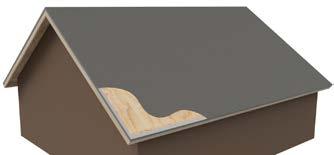
Decking: Sheathing must be structurally adequate to support the loads involved and of a material recognized in a code evaluation report or as approved by the local building official.
Underlayment: Unless otherwise noted, required underlayment shall be installed per IBC 1507 .3 .3 that conforms to: ASTM D 226, Type II; ASTM D 2626 or ASTM D 6380, Class M mineral- surfaced roll roofing.
For roof slopes from 2 .5:12 up to 4:12 underlayment shall be a minimum of two layers, See page 13
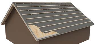
Battens: Nominal 1" x 2" complying with IBC Chapter 23, section 2302 for nominal size . Counter-batten systems and elevated or raised battens that meet these requirements are also acceptable
Eave Treatments: Bird Stop/Eave riser
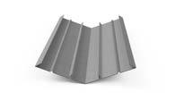
Valley Flashing: Shall extend each way 12" from center and have a center splash diverter rib 1" high See Table A on page 7 for more details
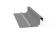
Wall Trays (Pans): Minimum 6" trough See Table A on page 7 for more details .
Head Wall: "Rigid metal of flexible flashing, 3" minimum lap over tile " See Table A on page 7 for more details
Pipe Flashing: Deck & Tile flashing is required. Medium and high profile tile flashing to be malleable flashings. See Table A on page 7 for more details
Counter Flashing: Z bar recommended or surface mount reglet (pin) Flashing for w . See Table A, page 7 for more details .
Fasteners: See page 9 and Tables 1A, 1B & 1C for requirements .
Ventilation: Per local building code requirements
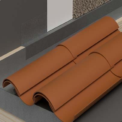
Roof tiles are typically of the following types: Low/Flat, Medium,and High Profile

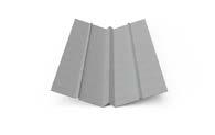
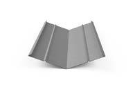
VALLEY FLASHING
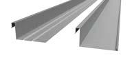
PAN FLASHING CHANNEL FLASHING WALL TRAYS FLASHING
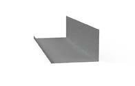
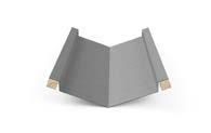
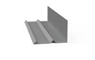
HEADWALL FLASHING ROOF TO WALL FLASHING APRON FLASHING
ROOF TO WALL FLASHING Z BAR FLASHING
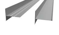
DRIP EDGE FLASHING EAVE FLASHING
RAKE FLASHING
CHIMNEY FLASHING SKYLIGHT FLASHING SADDLE FLASHING
PIPE FLASHING DECK FLASHING
NO 26 GAUGE GALVANIZED SHEET NOT LESS THAN 0 019"
ASTM A653 G90
MC-12B, MC-17, MC-17A, MC-17B
MC-12, MC-12A, MC-12B, MC-13, MC-13A
MC-11, MC-11A
MC-11, MC-11A
MC-10, MC-10A, MC-10B, MC-10C, MC-10D
MC-12B, MC-19, MC-19A
MC-14, MC-14A, MC-15, MC-15A, MC-16A, MC-16B
MC-02, MC-21
ROOF VENTS ATTIC VENTS MC-21
MALLEABLE FLASHING
SOFT LEAD NOT LESS THAN 2 .5 LBS / SQ .FT
DEAD SOFT ALUMINUM NOT LESS THAN 0 .019"
SOFT COPPER NOT LESS THAN 16 OZ/SQ FT or
Decay corrosion resistant water proof materials designed for exposure to elements
MC-02, MC-15A, MC16B, MC-17D, MC-11, MC-11A
Note: The flashing specifications stated in Table A are considered minimum requirements. For other materials, see IBC Tables 1507.4.3(1) and 1507.4.3(2) or IRC Tables R905.10.3(1) and R907.10.3(2), as applicable.
TYPE
BIRD-STOP
EAVE RISER
WEATHER BLOCKING
SPECIFICATION
PER MANUFACTURER
DETAILS
MC-10A, MC-10B, MC-10C, MC-23, MC-25
MC-10, MC-10B
MC-18, MC-18A, MC-18C
Freeze Thaw: Different climatic conditions will result in the need for different roofing materials that will allow the success of the roofing system over the long-term. Resistance to freeze/ thaw is very important in weathering situations where the roofing material is expected to withstand repetitive freezing and thawing cycles Both Concrete and Clay Tile used in these conditions must have passed the requirements of ASTM C1492 (Concrete) ASTM C1167 (Clay) for freeze thaw regions
Strength: A Concrete (ASTM C1492) or Clay tile’s (ASTM C1167) transverse strength will meet or exceed requirements of the specified codes.
Thickness : Roof tile typically ranges in thickness from 3/8" to 1½", depending upon composition, type and style .
Quantities of Tile Per Square: The size of the tile and the exposure of each course of tile determines the number of tiles needed to cover one square (100 sq ft ) of roof area When the tiles are installed at the manufacturer’s maximum exposure, the number of tiles needed to cover one square of roof area may range from 75 to over 400 pieces .
Tile Weight: The size of the tile and the exposure of each course will determine the installed weight of the roof tiles In general, the amount of tiles to cover one square (100 sq ft .) set at the standard 3 inch head lap, will depend on the thickness, length, width, shape and aggregate materials used in the manufacturing process of the tile . Please consult with the tile manufacturer when determining the weight of the specific tile that will be used. As with any roofing material the designer should always consider the weight of the underlayment, fastening system, roof accessories and special hip/ridge treatments
Concrete Tile: Cementitious materials such as portland cement, blended hydraulic cements and fly ash, sand, raw or calcined natural pozzolans and aggregates shall conform to the following Concrete Tile ASTM C1492 Specifications.
Clay Tile: Tiles are manufactured from clay, shale, or other similar naturally occurring earthly substances and subjected to heat treatment at elevated temperatures (firing). The heat treatment must develop a fired bond between the particulate constituents to provide the required strength and durability .
Clay Tile ASTM C1167 Specifications: Additional Standards for Concrete & Clay Tile may be referenced in the following additional standards:
IBC/IRC, ASCE 7-16, CC-ES AC 152, ICC-ES AC180, CAN/CSA–A220 1-M91, State and Local Building Codes
Adhesive: Bonding materials designed to adhere tiles to other tiles or substrate such as mortar, synthetic mortar, mastics, silicones, polymers, Tri-polymers, or other materials approved by the local building official. Contact the adhesive manufacturer for additional information . Refer to current evaluation reports of roof tile adhesives for installation requirements and conditions of use .
Batten: A sawed strip of wood installed horizontally and parallel to the eave line which is mechanically attached to the roof deck or rafters to engage the anchor lugs of the tiles, when applicable, to prevent slippage of the roof tile Battens of nominal 1"x 2"
lumber complying with IBC Chapter 23, section 2302 may be dimensionally increased in size to accommodate structural loads for snow or unsupported spans over counter battens or rafters Battens may also be corrosion resistant metal or other man-made material that meets the approval of the local building official. In dry/low humidity climates decay resistant battens are not required See Tables 1A,1B & 1C on pages 14 and 15
Battens installed over counter battens or those which span over rafters commonly are of soft wood, spruce, pine, or fir type species but may be of any type of lumber, metal or man-made materials that meet the approval of the local building official.
See table 2 on page 16
Counter Battens: Counter-batten systems and elevated or raised battens that meet these requirements are also acceptable Additional set of battens installed vertically and parallel to the roof slope and mechanically attached to the roof deck under the batten . Counter battens are commonly 1/4 inch lath but may be dimensionally increased in size to provide a greater flow of air or moisture beneath the horizontal battens . Counter battens do not need to be of decay resistant lumber as they do not impede moisture flow. Counter battens may also be of corrosion resistant metal or other man-made materials that meet the approval of the local building official. See table 2 on page 16.
Note: If counter battens are installed under the underlayment, caution must be used to prevent damage to underlayment or reinforced underlayment shall be used.
Note: Care should be taken in selecting the proper batten design. Excessive deflection of the batten may lead to tile breakage. See table 2 on page 16.
Caulking and Sealant: Caulking and sealants shall be suitable for exterior use and be resistant to weathering The caulking and sealants shall be compatible with and adhere to the materials to which they are applied
Nails and Fastening Devices: Nails and fastening devices must be corrosion resistant meeting ASTM A641 Class 1 or other approved corrosion resistance They must also be No 11 gauge diameter and of sufficient length to properly penetrate 3/4" into or through the thickness of the deck or batten, whichever is less The head of the nail used for tile fastening shall not be less-than 5/16" ( .3125") and complying with ASTM F 1667 for dimensional tolerances (+0%, -10%)
Nail Length:
Nailing of Batten— Nails for fastening battens shall have sufficient length to penetrate at least 3/4" into the roof frame or sheathing
Nailing Tile to Batten and Direct Deck Systems— Nails for fastening roof tiles shall penetrate at least 3/4" into the batten or through the thickness of the deck, whichever is less Once the batten is installed it becomes part of the deck for fastening purposes
Nailing Tile to Battens on Counter Batten— Nails for fastening roof tiles shall penetrate at least 3/4 . "
Nailing Accessories—Where nail(s) are required for fastening accessories, such nails shall have sufficient length to penetrate at least 3/4" into the supporting member .
Screws: Corrosion resistant meeting code approval equal of sufficient length to properly penetrate ¾" into or through the thickness of the deck or batten, whichever is less Screw diameter and head size should be selected to meet good roofing practices and the screw manufacturer’s recommendations . See above section on nail length for additional requirements
Staples for Battens: No 16 gauge by 7/16 inch-crown by minimum 1½ inch long corrosion-resistant staples .
Flashing: Flashing shall be installed at wall and roof intersections, wherever there is a change in roof slope or direction and around roof openings. Where flashing is of metal, it shall be a minimum of;
0 .019" Galvanized (G90)
0 019" Aluminum
16 Oz Copper
2 5 lb Soft Lead
Underlayment Materials: Unless otherwise noted, required underlayment shall be installed per IBC 1507 .3 .3 that conforms to: ASTM D 226, Type II; ASTM D 2626 or ASTM D 6380, Class M mineral-surfaced roll roofing. For roof slopes from 2½:12 up to 4:12 underlayment shall be a minimum of two layers, See page 13 .
Synthetics Underlayment material: Where synthetics are installed, please consult with the underlayment manufacturer to determine fit for use under concrete and clay tiles.
GENERAL INFORMATION—The TRI Alliance has created technical bulletins on many of these topics and more that can be found at www.tileroofing.org
Algae/Organic Growth: In certain climatic regions of the country, the development of algae and/or organic growth can occur on any building material The growth of moss and organic growth form on the dirt and moisture on the surface of the tile. Unlike other roofing materials, these items can easily be treated and do not deteriorate the roofing tile.
In most cases the use of a high pressure cleaner will remove the presence of the moss that traditionally grows in the dirt/pine needles or other debris that accumulates on the edge of the tile
Note that you may wish to contact a professional to clean your roof, since steep slope roofs can be dangerous to walk on when wet Caution of not spraying upslope or into side walls
Color Shading: Slight variations in sand, cement, and color oxides (natural products) can cause minimal color shading
This slight variance is not detectable through standard quality control practices . In order to minimize color patterning, stair stepping, or hot-spots, tiles should be selected and spread over the entire roof plane when loading the tiles onto the roof .
Broken Tile Replacement: To remove a broken tile, cut any fasteners, remove the broken pieces of tiles, remove the fasteners and repair the underlayment . If the tiles were installed on battens and the tile has batten lugs, a new tile may inserted to hang on the batten If no battens were used, a 12" x 6" by ½" plywood piece is nailed to the deck to act as a batten .
As an alternative, replacement tiles may be inserted using roofers mastic, hooks, wires or approved adhesives to bond at the head lap area . See page 67 (Tile Repair) .
Efflorescence: Efflorescence is a temporary surface discoloration common to all concrete based roofing tile. It is in no way detrimental to the overall quality, structural integrity, or functionality of the tile. Efflorescence is caused by the chemical nature of the cement. Manufactured cement contains free lime, and when water is added, a series of chemical reactions take place releasing calcium hydroxide which can form a white chalky crystalline salt deposit on the tile surface when reacting with carbon dioxide . This reaction can appear as an overall “bloom” (overall softening of color) or in more concentrated patches . See our technical bulletin at https:// tileroofing.org/industry/technical-briefs/.
It is difficult to predict how long the effects of efflorescence will last It depends on the type and amount of deposit as well as the local weather conditions . The action of carbon dioxide and rain water will gradually, in most cases, remove the deposit, leaving the original color of the concrete roof tile intact without further efflorescence.
Walkability: The inert nature of tile, its characteristics of strength over age, and its durability will contribute to a long term life expectancy With a good installation and reasonable precautions against severe roof traffic, a tiled roof system will require very low maintenance .
Walking on roofing tile should be avoided and only done with extreme caution Place antennas and roof mounted equipment where a minimum of roof traffic will be necessary for servicing and maintenance If necessary to walk on the tile surfaces pressure should only be applied on the head-lap of the tiles (lower 3-4 inches) This distributes the load near the bearing points of the tile When painting or repairing adjoining walls or appurtenances, tiles can be removed for the adjoining work and reset after the completed work requiring heavy foot traffic. The tile surface can also be safely covered with secured plywood or roof pads available from many roof tile manufacturers to distribute traffic loads and prevent dirt, building materials, and paint/stain from damaging or discoloring the tile If necessary to walk on the tile surfaces pressure should only be applied on the head-lap of the tiles (lower 3-4 inches) This distributes the load near the bearing points of the tile When painting or repairing adjoining walls or appurtenances, safely cover the tile surface with secured plywood to distribute traffic loads and prevent dirt, building materials, and paint/stain from damaging or discoloring the tile .
Weather Effects On Tile: After constant exposure to nature’s elements, some tiles can be expected to lighten to some degree from the original color or lose some surface texture . This is due primarily to the effects of oxidation on the surface of the tile This will not effect the structural integrity or water shedding ability of the tile
Vermin Screening: Metal, honeycomb plastic, foam fillers, mortar or equivalent should be considered to seal larger openings into the roof system . This will help minimize the access of birds and vermin infiltration.
Please consult with the individual manufacturer and local building officials for additional information
In locations where the January mean temperature is 25 deg. F (-4 deg C) or less or where ice damming often occurs, the TRI Alliance suggests reference to the Concrete and Clay Tile Roof Design Criteria Manual for Cold and Snow Regions.
Sheathing: Sheathing must be structurally adequate to support the loads involved and of a material recognized in a code evaluation report or as approved by the local building official.
Underlayment: Unless otherwise noted, required underlayment shall be installed per IBC 1507 3 3 that conforms to: ASTM D 226, Type II; ASTM D 2626 or ASTM D 6380, Class M mineral- surfaced roll roofing.
On roof slopes below 3:12 an approved multi-ply membrane roof such as a built-up roof system, applied in accordance with page 13, or a single-ply roof membrane assembly, or other underlayment systems approved by the local building official, is first installed.
Tile installed at less than 3:12 shall be considered decorative .
Where roof slopes fall between 3:12 and under 4:12, underlayment shall be as described in the previous paragraph, underlayments meeting ASTM D1970 (such as EPDM, Ice and Water Shield), or two layers of ASTM D226 Type II (No 30 felt) (ASTM D4869 Type IV), installed shingle fashion, or single ply roof membrane assembly installed per code, or other approved underlayments .
Roof Layout: To achieve the optimum performance and appearance, the roof area between the eave and ridge should be divided into equal tile courses when possible . A minimum 3-inch overlap must be maintained for all tile, tile courses unless precluded by tile design . The actual layout of the roof courses will be determined by the length of the roof courses the specific tile being installed. Profiled tiles can be installed either straight or staggered bond
Batten Installation: Tiles with projecting anchor lugs installed on battens below 3:12 slopes have one of the following batten systems or other methods as approved by the local building officials.
Nominal 1 inch by 2 inch, or greater, wood batten strips installed over a counter batten system are required for roof slopes below 3:12 in order to minimize penetrations of the waterproofing membrane by fasteners Nominal 1 inch by 2 inch, or greater, wood battens are required where slopes exceed 7:12, to provide positive tile anchoring Battens are nailed to the deck with 8D corrosion resistant box nails 24 inches on center, or No 16 gauge by 7/16 inch-crown by 1½ inch long corrosion-resistant staples 12-inch centers, allowing a 1/2" separation at the batten ends . Tile installed on roof slopes of less than 3:12 are considered
decorative only and must be applied on counter battens over an approved membrane roof covering, subject to local building official approval.
Battens installed on roof slopes of 4:12 to 24:12 shall be fastened to the deck at no greater than 24 inches on center, and shall have provisions for drainage by providing ½-inch separation at the batten ends every 4 feet, or by shimming with a minimum 1/4" material of wood lath strips, 2-inch shims, cut from multiple layers of material, placed between the battens and deck to provide drainage beneath the battens or other methods approved by the local building official. Tile installed without projecting anchor lugs may be installed as provided above as an optional method of installation
Counter Batten System – Counter battens 1/4" and larger in height will be installed vertically on the roof to provide the space between the battens, to which the tiles are attached, and the roof deck, thus facilitating air flow capability and moisture drainage. Taking the anticipated roof loading into account, design consideration should be given to the size and quality of the wooden battens or sheathing boards used to support the roof tile covering
If the battens are not strong enough to support the anticipated loading, including the roof tile and snow and/or ice, the battens could deflect between the support points causing roof tile breakage and/or other roof damage Knots and knot holes weaken the batten . See Table 2 on page 12 . If a counter batten system is to be installed under the underlayment, caution must be used to prevent damage to the underlayment or a reinforced underlayment will be used
Re-Roof: Prior to installation, all foreign matter will be cleaned from all interlocking areas Cracked or broken tile must be removed from the roof. Damaged, rusted, improper flashing will be replaced when re-roofing.
For re-roof, clay and concrete roofing tiles, recognized as a Class A roof assembly passing testing according to ASTM E 108, UL 790 or recognized in accordance with IRC section R902 .1, may be allowed to be installed over existing asphalt shingles, plywood or OSB In lieu of such underlayments being provided, the building official has the discretion to determine if the existing roof covering provides the required underlayment protection. Check with local building official for any additional requirements .
The need for proper attic ventilation, in accordance with the IBC and IRC, is required by most building code authorities These codes recognize that the proper ventilation is a necessary component of any successful steep slope roof system . Generally building codes require that a minimum net free
ventilating area for attic vents be a 1:150 ratio of the attic space being ventilated The codes generally allow for the reduction of the ratio from 1:150 to 1:300 if the attic vents are a balanced system on a roof and/or a vapor retarder is installed on a ceiling assembly’s warm side. Check with local building official for regional requirements for ventilation .
(Replaces Table 1A and 1B in previous manuals)
Please see International Building Code (IBC), International Residential Code (IRC) and local building codes for addition requirements.
Underlayment: Unless otherwise noted, required underlayment shall be installed per IBC 1507 3 3 that conforms to: ASTM D 226, Type II; ASTM D 2626 or ASTM D 6380, Class M mineral- surfaced roll roofing.
Low-slope roofs: For roof slopes from 2 1/2 : 12 up to 3:12, see page 11 .
High-slope roofs:
1) For roof slopes of 4:12 or greater, underlayment shall be a minimum of one layer of underlayment felt applied shingle fashion, parallel to, and starting from the eaves and lapped 2 inches, fastened only as necessary to hold in place
2) Starting at the eave, a 19-inch strip of underlayment shall be applied parallel with the eave and fastened sufficiently in place
3) Starting at the eave, 36-inch-wide strips of underlayment felt shall be applied overlapping successive sheets 19 inches and fastened sufficiently in place.
High wind attachment:
1) High wind as defined to be wind design velocities, Vasd, greater than 110 mph as determined in accordance with IBC Section 1609 .3 .1 shall be applied with corrosion-resistant fasteners in accordance with the manufacturer’s installation instructions . Fasteners are to be applied along the overlap not more than 36 inches on center
2) High wind [Vasd, equals or exceeds 120 mph] shall be attached in a grid pattern of 12 inches between side laps with a 6-inch spacing at the side laps Underlayment shall be applied in accordance with Sections 1507 3 3 1 and 1507 3 3 2 except all laps shall be a minimum of 4 inches .
Underlayment shall be attached using metal or plastic cap nails with a head diameter of not less than 1 inch with a thickness of at least 32-gage (0 .0134 inch) sheet metal . The cap nail shank shall be a minimum of 12 gauge (0 105 inch) with a length to penetrate through the roof sheathing or a minimum of 3/4 inch into the roof sheathing
Exception: As an alternative, adhered underlayment complying with ASTM D 1970 shall be permitted .
Tile Fastener: Tile fasteners shall be corrosion resistant and not less than 11-gage, 5/16-inch head, and of sufficient length to penetrate the deck a minimum of 3/4 inch or through the thickness of the deck, whichever is less . Attaching wire for clay or concrete tile shall not be smaller than 0 083 inch Perimeter fastening areas include three tile courses but not less than 36 inches from either side of hips or ridges and edges of eaves and gable rakes .
ONE FASTENER PER TILE FLAT TILE WITHOUT VERTICAL LAPS, TWO FASTENERS PER TILE
TWO FASTENERS PER TILE ONLY ONE FASTENER PER TILE ON ROOF SLOPES OF 7:12 AND LESS FOR TILES WITH INSTALLED WEIGHTS EXCEEDING 7 5 LBS/SQ FT HAVING A WIDTH NO GREATER THAN 16 INCHES
THE HEAD OF ALL TILES SHALL BE NAILED . THE NOSE OF ALL EAVE TILES SHALL BE FASTENED WITH APPROVED CLIPS ALL RAKE TILES SHALL BE NAILED WITH TWO NAILS THE NOSE OF ALL RIDGE, HIP AND RAKE TILS SHALL BE SET IN A BEAD OF ROOFERS MASTIC
THE FASTENING SYSTEM SHALL RESIST THE WIND FORCES IN IBC SECTION 1609 5 3
THE FASTENING SYSTEM SHALL RESIST THE WIND FORCES IN IBC SECTION 1609 5 3
THE FASTENING SYSTEM SHALL RESIST THE WIND FORCES IN IBC SECTION 1609 5 3
THE FASTENING SYSTEM SHALL RESIST THE WIND FORCES IN IBC SECTION 1609 5 3
INTERLOCKING CONCRETE OR CLAY TILE WITH PROJECTING ANCHOR LUGS D,E
(Installations on spaced/solid sheathing with battens or spaced sheathing)
FASTENERS NOT REQUIRED TILES WITH INSTALLED WEIGHT LESS THAN 9 LBS/ SQ FT REQUIRE A MINIMUM OF ONE FASTENER PER TILE
ONE FASTENER PER TILE EVERY OTHER ROW ALL PERIMETER TILES REQUIRE ONE FASTENER TILES WITH INSTALLED WEIGHT LESS THAN 9 LBS/SQ FT REQUIRE A MINIMUM OF ONE FASTENER PER TILE
ONE FASTENER REQUIRED FOR EVERY TILE . TILES WITH INSTALLED WEIGHT LESS THAN 9 LBS/ SQ FT REQUIRE A MINIMUM OF ONE FASTENER PER TILE
THE HEAD OF ALL TILES SHALL BE NAILED THE NOSE OF ALL EAVE TILES SHALL BE FASTENED WITH APPROVED CLIPS ALL RAKE TILES SHALL BE NAILED WITH TWO NAILS THE NOSE OF ALL RIDGE, HIP AND RAKE TILES SHALL BE SET IN A BEAD OF ROOFERS MASTIC
INTERLOCKING CONCRETE OR CLAY TILE WITH PROJECTING ANCHOR LUGS (Installations on solid sheathing without battens
The head of all tiles shall be nailed The nose of all eave tiles shall be fastened with approved clips . All rake tiles shall be nailed with two nails The nose of all ridge, hip and rake tiles shall be set in a bead of roofers mastic
The fastening system shall resist the Wind Forces in IBC Section 1609 5 3
The fastening system shall resist the Wind Forces in IBC Section 1609 .5 .3
The fastening system shall resist the Wind Forces in IBC Section 1609 .5 .3
The fastening system shall resist the Wind Forces in IBC Section 1609 5 3
Notes:
1. Minimum fastener size. Corrosion-resistant nails not less than No. 11 Gage with 5/16 inch head. Fasteners shall be long enough to penetrate into the sheathing 3/4 inch or through the thickness of the sheathing, whichever is less. Attaching wire for clay and concrete tile shall not be smaller than 0.083 inch.
2. Snow areas. Minimum of two fasteners per tile are required or battens and a fastener.
3. Roof slopes greater that 24:12. The nose of all tiles shall be securely fastened.
4. Horizontal battens. Battens shall be not less that 1 inch by 2 inch nominal. Provisions shall be made for drainage by a minimum of 1/8 inch riser at each nail or by 4-foot -long battens with at least a 1/2-inch separation between battens. Horizontal battens are required for slopes over 7:12.
5. Perimeter fastening includes three courses but not less than 36 inches from either side of hips or ridges and edges of eaves and gable.
6. Vasd (Average Strength Design) shall be determined in accordance with IBC section 1609.3.1
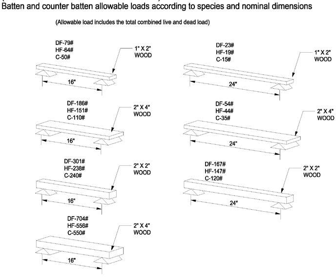
NOTES: HF = Hem Fir, DF = Douglas Fir, C = Western Cedar (spaced at 1’0" maximum on center) (above values were based upon stress rated boards) The above table was created as part of the TRI Cold Weather Installation Guide for additional recommendations in cold weather applications, available at www.tileroofing.org
Counter Batten System
Refer to Counter Batten Systems (Page 6) & MC-05 / MC-06A
2 ½ / 12 (21%) TO LESS THAN 3/12 (25%)
3/12 (25%) TO 7/12 (58.3%)
Counter-batten systems and elevated or raised battens that meet these requirements are also acceptable .
GREATER THAN 7/12 (58 .3%)
Not Required
See below for special climatic conditions
Nominal* 1" x 2" x 4’ (min 1/2" separation between battens)
Nominal* 1" x 2" x 8’ (Provision for drainage beneath batten with min 1/4" thick decayresistant riser at each fastener)
Nominal*: Refer to IBC, Chapter 23 (WOOD), SECTION 2302 (DEFINITIONS) .
Allowable Loads: When using counter battens, refer to Table 2 for additional load considerations
Batten Fastening: 24" OC to the deck with 8d corrosive resistant nails . 12" OC to the deck with No 16 gauge by 7/16-inch crown by 1 1/2-inch long corrosive-resistant staples
Once the batten is installed, it becomes part of the deck for fastening purposes
Climatic Conditions: In dry/cool humidity climates, moisture resistant battens are not required . Consideration should be given to lower slope roofs that are susceptible to wind driven snow and rain Optional upgrades should be considered
Alternates:
Corrosion resistant metal, or other man-made MC-06A material that meets the allowable loads (see Table 2), in a valid and approved evaluation report ,and/or approval of the local building official.
Nominal* 1" x 2" x 4’ or less (min ½" separation between battens)
Nominal* 1" x 2" x greater than 4’
(Provision for drainage beneath batten with min ¼" thick decay-resistant riser at each fastener)
Counter Batten
Refer to Counter Batten Systems (Page 11) & MC-05 / MC-06A
Alternates
Corrosion resistant metal, or other man made material that meets the approval of the local building official and/or a valid and recognized batten system
Counter Batten
Refer to Counter Batten Systems (Page 6) & MC-05 / MC-06A
Alternates:
Corrosive resistant metal, or other man made material that meets the approval of the local building official and/or a valid and recognized batten system
NOTE: In Cool/Humid climates raised, scalloped, counter or other batten systems that provide positive drainage are required.

VENT
PLUMBING VENT (SOIL) PIPE STACK
CHIMNEY: A penetration constructed of stone, masonry, prefabricated metal, or a wood framed chase containing one or more flues, projecting through and above the roof.
DORMER: A frame projection through the sloping plane of a roof
EAVE: A projecting edge of a roof that extends • beyond the supporting wall .
FIELD OF ROOF: The central or main portion of a roof, excluding the perimeter and flashings.
GABLE: A triangular portion of the end wall of a building directly under the sloping roof and the eave line
GUTTER: A channeled component installed along the downslope perimeter of a roof to the drain leaders or down spout
HIP: The inclined external angle formed by the intersection of two sloping roof planes
HEAD WALL: Flashing installed at a horizontal roof to wall
RAKE EDGE: The sloped edge of a roof at or adjacent to the first rafter or truss .
RAKE: The area used to cover the intersection between the gable and end of roof .
RIDGE: The highest point of a roof, represented by a horizontal line where two roof areas, intersect, running the length of the area
RIDGE VENT: A roof accessory designed for use as a vent along the ridge of a roof system .
ROOF VENT: A penetration through the roof to allow ventilation
SKYLIGHT: A roof accessory, set over an opening in the roof, designed to admit light, normally transparent, and mounted on a raised curb .
SOFFIT: The underside of any exterior overhanging section of the roof eave
PLUMBING (SOIL) STACK: A sanitation pipe that penetrates the roof; used to vent plumbing fixture(s).
VALLEY: The internal angle formed by the intersection of two sloped roofing planes.
2"HEADLAP MINIMUM
END LAP OF A MINIMUM OF 6"
FELT MUST BE TURNED DOWN OVER RAKE EDGE A MINIMUM OF 1" OR RAKE METAL FLASHING INSTALLED
ROOF DECK
SUCCEEDING COURSES OF APPROVED UNDERLAYMENT WITH MINIMUM 2" SIDELAP AS APPROVED BY LOCAL BUILDING CODES
UNDERLAYMENT FASTENED TO RESIST WIND DAMAGE
FASTENING METHODS MAY BE USED AS APPROVED BY LOCAL BUILDING OFFICIALS
FASTENERS SHALL BE DRIVEN FLUSH TO ROOF FELT . ANY PUNCTURE AND/OR TEAR IN FELT MUST BE SEALED WITH MEMBRANE COMPATIBLE SEALANT OR ADDITIONAL UNDERLAYMENT
NOTE: Roof slopes below shall have an approved built up roof membrane applied in accordance with Table 1A, or a single ply roof membrane system, or other multi-ply-underlayment system(s) approved by the local building official.
NOTES:
1. Ensure that the roof deck is properly fastened, clean and smooth before underlayment and roof tiles are applied.
2. Verify that the roof deck has no significant delamination, warp-age, etc. Check roof deck decay or damage.
3. Make sure repairs are made to roof deck as necessary to meet local building codes.
4. Most problems with water-shedding roof installations occur from water that migrates through improper flashing of the tile, wind-driven rain or ice damming. Because of this possibility, the underlayment is critical to the success of the roof system.
5. For recommended underlayment and fastening, see Page 13, Table 1A, 1B & 1C.
6. Underlayment should extend a minimum of 4" up the vertical wood blocking or wall. Laps should be a minimum of 6" end lap (vertical lap) and 2" headlap.
(Required for 3:12 < Roof Slope < 4:12, Optional Upgrade 4:12 And Above)
FELT MUST BE TURNED DOWN OVER RAKE EDGE A MINIMUM OF 1" OR RAKE METAL FLASHING INSTALLED
UNDERLAYMENT AS APPROVED BY LOCAL BUILDING OFFICIAL
DRAWING DEPICTS TYPICAL 36" WIDE ROLLS LAPPED 19"
ICE DAM PROTECTION WHERE REQUIRED (SEE TABLES 1A, 1B, 1C)
DRIP EDGE
INSTALL 18" WIDE FIRST COURSE
INSTALL FULL 36" WIDE SECOND COURSE
NOTES:
1. Ensure that the roof deck is properly fastened, clean and smooth before underlayment and roof tiles are applied.
1. Verify that the roof deck has no significant delamination, warp-age, etc. Check roof deck decay or damage.
2. Make sure repairs are made to roof deck as necessary to meet local building codes.
3. Apply a half sheet parallel to eave. Fasten underlayment sufficient to hold the felt in place.
4. Completely cover the starter sheet with a full-width sheet.
5. Most problems with water-shedding roof installations occur from water that migrates through improper flashing of the tile, wind-driven rain or ice damming. Because of this possibility, the underlayment is critical to the success of the roof system.
6. Underlayment should extend a minimum of 4" up the vertical wood blocking or wall.
7. Lap succeeding sheets to ensure double layers over the entire roof. End laps (vertical lapse) shall be a minimum of 6".
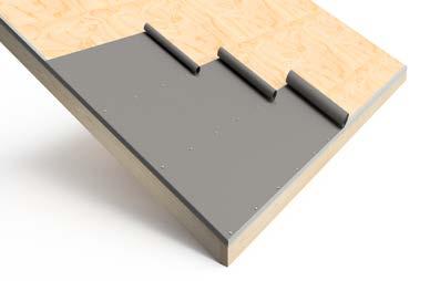
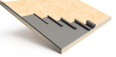
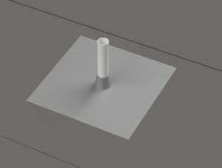
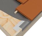
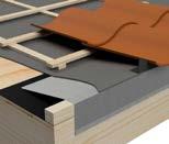
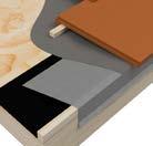
STEP 1 - DECK FLASHING
(Shows Required Two-Step Deck and Tile Flashing)
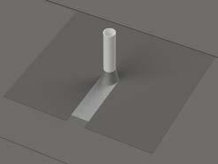
STEP 3 - TILE FLASHING
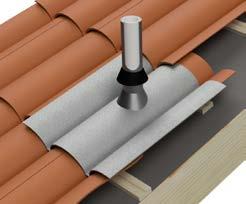
PENETRATION COVERED WITH DECK FLASHING
UNDERLAYMENT
STEP 2 - UNDERLAYMENT COURSING ALL PENETRATIONS SHOULD BE LOCATED IN SUCH A MANNER AS TO NOT IMPEDE FLASHINGS AT ROOF TRANSITIONS
NOTES:
1. For recommended underlayment and fastening, see Page 13, Table 1A, 1B & 1C
2. All penetrations require a deck and tile flashing.
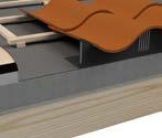
PREFORMED FLASHING INTEGRATED INTO UNDERLAYMENT (INSTALLED TO PREVENT MOISTURE FROM PENETRATING ROOF DECK . OPTIONAL STRIPPING, THREE COURSING WITH ASPHALT ROOF CEMENT AND REINFORCING FABRIC FOR INSTALLATION OF DECK FLASHING WHEN PERMITTED BY LOCAL BUILDING OFFICIAL
UNDERLAYMENT INSTALLED OVER DECK FLASHING, COURSED UNDER LAYER ABOVE
STORM COLLAR ON CONE STYLE FLASHING
PROFILE TILE FLASHING (CONFORM SHEET LEAD OR OTHER MALLEABLE FLASHING TO PROFILE OF TILE) TO MAINTAIN DRAINAGE TO TOP OF TILE BATTEN (WHERE REQUIRED)
3. Tile flashings shall extend onto the tile a minimum of 4" on flat tile and a minimum of 1" past the crown of the tile of a profiled tile.
4. Dimensions shown are minimum and intended to be approximate to allow for reasonable tolerances due to field conditions.
5. For flat tile, a rigid flashing material may be used.
WOVEN UNDERLAYMENT (METAL FLASHING NOT SHOWN)
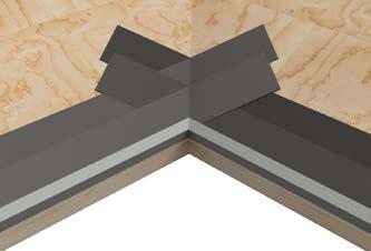
SINGLE LAYER DOUBLE LAYER
ROOF DECK
SINGLE LAYER FELT
UNDERLAYMENT WOVEN TO EXTEND THROUGH VALLEY CENTER LINE A MINIMUM OF 12"
ROOF DECK
UNDERLAYMENT WOVEN BETWEEN COURSES
NOTE:
1. The underlayment options shown on MC-03 or MC-03A are acceptable options for any metal configuration.
2. See MC -12B for additional considerations.
3. For recommended underlayment and fastening, see Page 13, Table 1A, 1B & 1C. Drawing shown depicts the application of all tile profiles. Unless otherwise noted, it would apply to either concrete or clay tiles.
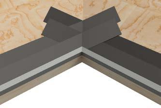
OVERLAPPING UNDERLAYMENT This method not to be used with standing hem valley metal
UNDERLAYMENT TO LAP OVER VALLEY METAL A MINIMUM OF 2"
NOTES:
1. For recommended underlayment and fastening, see Page 13, Table 1A, 1B & 1C
36" BLEEDER STRIP
ROOF DECK
NOTE:
Underlayment options shown in MC-03 or MC-03A are acceptable options for any code approved metal. See MC-12B for additional considerations.
ROOF DECK
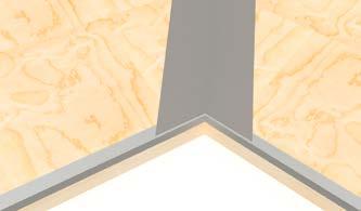
VALLEY FLASHINGS
OPTIONAL: SELF ADHERING POLYMER MODIFIED ASPHALT MEMBRANE ON EACH SIDE TO COVER FLASHING FLANGE
CUT TOP CORNER OF UNDERLAYMENT TO ENSURE PROPER DIVERSIONS OF WATER INTO THE VALLEY METAL
ROOF UNDERLAYMENT
VALLEY FLASHING (EXTEND ENTIRE WIDTH OF VALLEY METAL BEYOND ROOF EDGE)
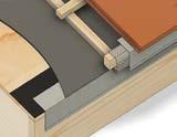
FOR TILES WITH PROTRUDING
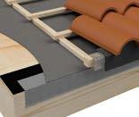
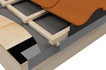
(Do not mix batten options on a roof)
NOTE:
DIRECT DECK - NO BATTENS USED IN DIRECT DECK APPLICATIONS CAN BE EI THER STYLE OF TILE
OPTIONAL METHODS:
BATTENS WITH SHIMS BATTENS WITHOUT SHIMS
4FT MAX LENGTH WITH 1/2"SEPARATION THAT MAY BE VERTICALLY ALIGNED OR OFFSET
DISTANCE DETERMINED FOR MINIMUM 3" HEADLAP BASED ON TILE LENGTH
OPTIONAL PORTED BATTEN: MIN 1/2" WIDE X 1/4" DEEP WITH DRAINAGE PORTS MIN 2 FT ON CENTER OPTIONAL RAISED OR ELEVATED BATTEN SYSTEMS WITH CODE APPROVAL ARE ALLOWED
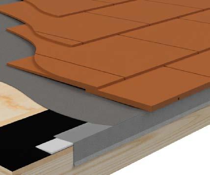
Using a full tile, determine desired overhang at eave and snap a horizontal chalk line across roof at the head of a tile or top of batten. Consider tile dimensions, eave closure and eave/gutter detail to determine desired overhang. First row chalkline must adjust for direct to deck or batten installation.

OPTIONAL PORTED BATTEN: MIN 1/2" WIDE 1/4" DEEP DRAINAGE PORT MINIMUM OF 2 FT ON CENTER
NOTES:
OPTIONAL BATTENS WITH SHIMS, RAISED PADS
1. For recommended underlayment and fastening, see Page 13, Table 1A, 1B & 1C.
2. Battens shall not be less than nominal inch by inch or other code approved products.
OPTIONAL BATTENS WITH SCALLOP OR OTHER DRAINAGE DESIGNS
3. Battens shall be no longer than 48" and separated with 1/2" minimum gaps at ends to allow for drainage. An alternative method permits the use of longer batten strips with shims of minimum 1/4" thick decay resistant material (e.g. asphalt shingle, woods strips or cap sheet) at fastener to provide drainage, or other methods as approved by local building official.
4. Fasten battens a minimum of 24" on center with minimum 8d corrosion-resistant nails penetrating through decking or into structural framing. Batten attachment at 12" on center with staples a minimum of 1-1/2" long 7/16" crown, No 16 gauge corrosion-resistant allowing for a 3/4" penetration into roof deck or protrude min 1/4" through sheathing which ever is less or 24" centers if fastening directly to structural framing.Consideration should be given to climate and roof orientation to determine if it is beneficial to specify/use vertical battens over underlayment, with horizontal battens secured over vertical battens.
5. See Table 2 and Table 3 for additional batten considerations.
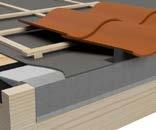
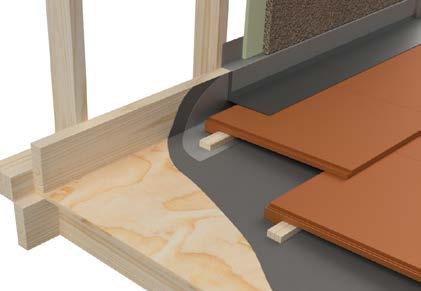
NOTE:
SEE TABLE 2 FOR SIZE AND SPACING OF VERTICAL BATTENS (24" MAX SPACING BETWEEN VERTICAL BATTENS)
HORIZONTAL BATTENS
VERTICAL BATTENS MINIMUM 1/4" THICKNESS
DISTANCE DETERMINED FOR 3" HEADLAP BASED ON TILE LENGTH WHERE FASTENING TO FRAMING MEMBER IS DESIRED, MARK AFTER LOCATION AS FELT IS BEING APPLIED
Consideration should be given to climate roof orientation to determine if it is beneficial to specify/use vertical battens over underlayment, with horizontal battens secured over the vertical battens.
BATTEN TERMINATION (OPTIONAL) SEE TABLE 3
NOTES:
1. For recommended underlayment and fastening, see Page 13, Table 1A, 1B & 1C.
2. Horizontal batten shall be sufficient to fully engage protruding anchor lugs of the tile.
3. See Table and for additional information.
4. Fasten battens a minimum of 24" on center with minimum 8d corrosion-resistant nails penetrating through decking or into structural framing. Batten attachment at 12" on center with staples a minimum of 1 1/2" long 7/16" crown, No 16 gauge corrosion-resistant allowing for a penetration into roof deck or protrude 3/4" min through sheathing which ever is less or on 24" centers if fastening directly to structural framing.
Any flashing with outside edges raised to the height of the vertical or horizontal battens

EDGE STRIP
VERTICAL BATTEN
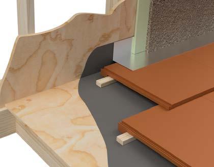
PROVIDE 2" MINIMUM CLEARANCE FOR AIRFLOW AND DRAINAGE
REFER TO MC-03 FOR WOVEN UNDERLAYMENT
REFER TO MC-17 FOR FINISH DETAIL
REFER TO MC-17B FOR DEEP TROUGH DETAIL
DEEP TROUGH VALLEY
NOTES:
1. For recommended underlayment and fastening, see Page 13, Table 1A, 1B & 1C
2. Consideration should be given to climate and roof orientation to determine if it is beneficial to specify/use vertical battens over underlayment, with horizontal battens secured over vertical battens.
Drawing shown depicts the application of all tile profiles. Unless otherwise noted, it would apply to either concrete or clay tiles.
VALLEY FLASHING
(EXTEND ENTIRE WIDTH OF VALLEY METAL BEYOND ROOF EDGE EQUAL TO OVERHANG OF TILE)
BATTENS WITH 2" GAPS FOR AIR FLOW AND DRAINAGE AT MIN 48" O C
VERTICAL BATTEN
PROVIDE MINIMUM 2" GAP FOR AIRFLOW AND DRAINAGE
REFER TO MC-03A FOR OVERLAPPING UNDERLAYMENT
REFER TO MC-17B FOR FINISH DETAIL
NOTES:
1. For recommended underlayment and fastening, see Page 13, Table 1A, 1B & 1C
2. Horizontal battens shall be not less than 1" x 2" or code approved equal.
3. Consideration should be given to climate and roof orientation to determine if it is beneficial to specify/use vertical battens over underlayment, with horizontal battens secured over vertical battens.
4. See Table and Table for additional considerations.
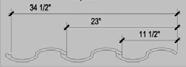
Based on a roof tile that has an exposed width of 11 ½" individually or 34 ½" for three tiles.
Variable designation denotes that the starting line may be adjusted in order to control the location of the ending line for purpose of balancing the symmetry of the roof layout. This allows the roofer to start with a half tile and end with a pan tile which facilitates the even application of the rake trim tiles.
Vertical alignment on interlocking tiles is, for the most part, controlled by the natural seat of the interlocking channels of the adjacent tiles
It is important however to establish true vertical alignment prior to application of field tiles to assure a symmetrical installation. Proper roof layout greatly enhances the appearance and performance of the installed roof and serves to simplify and speed the application of the tiles A few minutes devoted to layout at the beginning of the job can result in significant savings of time and effort as the job progresses.
On a gable roof installation, the first vertical guideline is established by installing the first three tile of the eave course and measuring the distance from the leading edge of the third tile to the rake This increment is then marked at the ridge course and a chalk line is snapped to delineate the vertical guide .
The exposed width dimension of the tile is then determined and measured from the vertical gable as frequently as needed to maintain proper alignment Most often this measurement is marked in threetile increments Vertical lines shall be perpendicular to the eave
Mark the point at the eave line as close to the center of the hip as possible Measure a point away from either side of the center point (5’-10’) if possible, making sure that both marks are the same distance from the center line . Using a tape measure or lines of the exact same length, swing an arc away from each mark to intersect as high on the hip as possible Intersection point of the arc represents the high point of the vertical line above the mark made near the center of the eave line A chalk line may be snapped to provide vertical reference Incremental measurements may then be taken in either direction from this center line to provide guidance for vertical alignment
On small hip sections, careful attention to horizontal alignment and proper tile placement is usually adequate to maintain vertical alignment. On larger roof sections, it is helpful to establish solid vertical alignment to ensure uniform appearance and ease of application.
Utilizing specially marked measuring tape
To achieve optimum beauty, the area between the eave and the ridge should be divided into equal tile courses, when possible. Minimum 3" overlap must be maintained for all tiles unless design of tile precludes . (see MC-04 for batten applications)
TOP COURSE MARK AT 1-1/2" FROM CENTER OF RIDGE
1.
HORIZONTAL
1 . Using a full tile, determine desired overhang at eave and snap horizontal chalk line across roof at head end of tile or top batten Use of rain gutter and eave closures should be considered in determining overhang
2 At top of roof deck, mark a reference point by measuring 1-1/2" from the center of the ridge, plus the distance of a full course (i e 15" for a 18" tile length tile)
3 Measure up the roof slope to the reference point and divide by the manufacturers maximum exposure in an effort to determine if the roof section will terminate with a full tile .
4 Mark roof deck for each course of tile and snap chalk lines over entire roof
5 If roof section does not terminate with a full tile at the ridge, decrease the course exposure in small increments (typically 1/4") in an attempt to finish with a full tile at the ridge.
6 If the last course does not terminate with a full tile, cut to dimension, as required and fasten with a mechanical fastener or approved fastening method
MARK FIRST COURSE FOR DESIRED OVERHANG
Note:
Additional considerations may be required for venting.
Consider size and placement of gutter when setting first course overhang.
1 . To ensure proper vertical alignment, determine the manufacturers stated maximum on-center spacing requirements and snap chalk lines as reference points, typically the inside of the tile .
2 . For gable end roof sections, determine the proper distance from the left and right rakes and mark the eave and ridge section to align the edge of the tiles .
3 . Measure between the two marks and divide by the manufacturers stated maximum on-center spacing If required, decrease the oncenter spacing, slightly in an effort to terminate a full tile at gable end(s) . Ensure that the tile are within the manufactures minimum/ maximum on-center spacing requirements
Note: Tiles are allowed, by ASTM C1167/C1492 for a plus or minus 5% variance from the manufacturers stated “nominal dimensions”. It is the installer’s responsibility to verify the “delivered” roof tiles dimensions prior to commencing roof layout and to ensure that the tile is installed with in the manufacturers minimum headlap and on-center spacing requirements. Most diagonal-cut tile will allow slight course exposure adjustments, typically 1/4" per tile.
Course spacing table - for tiles 16 ½" to 17" in length
To achieve optimum beauty, the area between the eave and ridge should be divided into equal courses, when possible Minimum 3" headlap must be maintained for all tiles unless design precludes 17" ONLY
16 1/2" - NOT TO EXCEED 13 1/2"
Spacing “C” from MC-08
Course
NOTES:
1. Using a full tile, determine desired overhang at eave and snap horizontal chalk line across roof at head end of tile or top batten. Use of rain gutter and eave closures should be considered in determining overhang.
2. Snap a horizontal chalk line at the top of the roof from center of the ridge. (Adjust for direct deck)
3. In spacing guide, find column containing nearest figure to the measurement between the eave and ridge course.
4. Mark both ends of roof at course spacing shown in column.
5. Snap chalk lines across roof at course markings.
6. Nail top batten to chalk line.
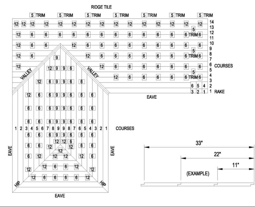
The method of roof lading shown on this page represents the method of tile placement for efficient application, but is not intended to suggest that this is the only method that will work . Each applicator will have personal preference for the stack location and spacing . The important aspect of tile loading is to spread the load evenly across the roof while using proper increments that assure that the proper amount of tile are roof loaded
NOTES:
1. Course lines should be measured and chalked according to the roof layout plan before loading the tile.
2. Determine the appropriate number of tiles needed for each section of the roof.
3. Spacing of the tile stacks is determined by the width of the exposed tile times the number of tiles being fed per course, e.g. in the attached schematic, each stack of tiles will feed two courses, three tiles wide. If each tile is exposed 11", then the stack will be placed 33" O.C. If the stacks feed three courses, two tiles wide, then the stacks will be 22" O.C.
4. Starting with the third course from the eave, and continuing with alternate courses, distribute tiles (usually 6 per stack) over the entire roof leaving 20" from gable ends and between stacks.
5. When total number of courses is an even number, stack tiles on ridge stacks. When the total number of courses is an odd number, stack tiles on the ridge stacks.
6. On the right side of the hips and valleys, stack 12 tiles. Maintain at least 24" between tile stacks and left side of valley. Reverse for tiles laid left to right.
7. Distribute trim tiles when loading field tiles. Trim tiles are in stacks of 5 at 70" O.C. Load ridge tile on side of roof to be applied last.
8. To achieve pleasant, random blend of color for your job, care should be taken upon loading to mix tile.
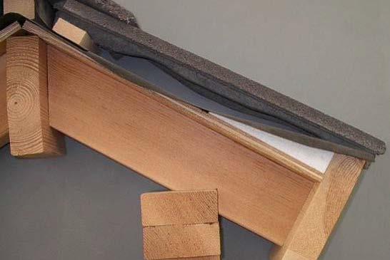
ANTI-PONDING STRIP
RISER VENT
DRIP FLASHING
UNDERLAYMENT
Risers
FLASHING
2. Bird stop may be either solid or vented.
METAL EAVE CLOSURE (WITH WEEP HOLE FOR DRAINAGE)
DRIP FLASHING
COVER METAL MIN 3/4" SPACE BETWEEN DRIP FLASHING & COVER METAL
OPTIONAL SCREEN FASTENED TO DECK WRAPPED OVER BATTEN ENDS
NAILER ADDED TO ADJUST TO PROPER HEIGHT METAL DRIP FLASHING
BATTEN
BIRD STOP W/ VENT (OPTIONAL)
3. Optional separator ply or sheet of No. 15 asphalt-saturated felt or other appropriate material.
OPTIONAL SCREEN FASTENED TO DECK WRAPPED OVER BATTEN ENDS
METAL EAVE RISER/ CLOSURE STRIP (WITH WEEP HOLES FOR DRAINAGE)
BATTEN (NOMINAL 1" X 2"MINIMUM) WHERE REQUIRED
UNDERLAYMENT
EAVE DRIP EDGE FLASHING
ANTI-PONDING STRIP
Width of anti-ponding device will increase on lower slopes to provide positive drainage. see note 2
RAISED FASCIA BOARD SEE NOTE 6
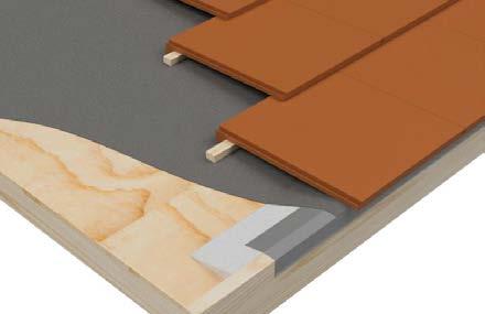
NOTES:
1. For recommended underlayment and fastening, see page 13, Table 1A, 1B & 1C
2. An anti-ponding device such as a beveled cant strip or shop-formed sheet metal is required at all raised fascia conditions to support the underlayment and provide positive drainage.
3. The tile and/or batten fasteners must penetrate a minimum into dimensional wood decking or pass through wood panel sheathing whichever is less. Once the batten is installed, it becomes part of the “deck” or substrate for tile fastening.
4. Raise fascia board above roof deck to height equal to combined thickness of batten system and thickness of one course of tile.
5. Dimensions shown are minimums and are intended to be approximate to allow for reasonable tolerances due to field.
6. Since raised fascia and starter strips create the same type of water dam situation, they both require an anti-ponding system to allow water to flow off the roof.
BATTEN WHERE REQUIRED
WIND CLIP WHERE REQUIRED UNDERLAYMENT
EAVE BLEEDER STRIP OR UNDERLAYMENT IF REQUIRED BY LOCAL BUILDING CODES
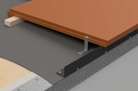
METAL EAVE RISER STRIP/CLOSURE (WITH WEEP HOLES FOR DRAINAGE)
EAVE DRIP EDGE FLASHING
EXTERIOR WALL OR FASCIA
NOTES:
1. For recommended underlayment and fastening, see page 13, Table 1A, 1B & 1C .
2. A drip edge flashing is required for all tile profiles.
3. Battens for tiles with protruding anchor lugs are optional for slopes between and less than or equal to . Direct deck nailing attachment of tile is permissible.
4. Dimensions shown are minimums and are intended to be approximate to all for reasonable tolerances due to field conditions.
See table 1a and 1b for underlayment requirements
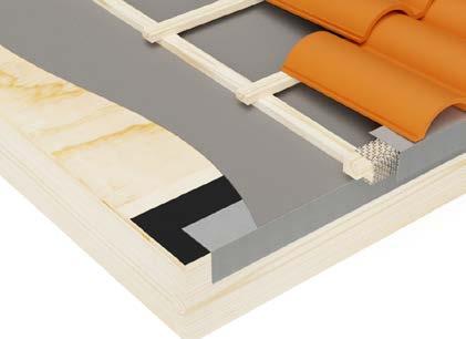
HIGH PROFILE TILE WITH BIRD STOP
NOTES:
1. For recommended underlayment and fastening, see page 13, Table 1A, 1B & 1C.
2. An eave drip edge flashing is required at all downslope perimeter edges.
NAILER ADDED TO ADJUST TO PROPER HEIGHT
COVER METAL (MIN SPACE BETWEEN DRIP FLASHING & COVER METAL
OPTIONAL: SCREEN FASTENED TO DECK WRAPPED OVER BATTEN ENDS PER LOCAL CODE
EAVE DRIP EDGE FLASHING
VENTED BIRD STOP
VERTICAL BATTEN EXTEND MINIMUM PAST EAVE FOR VENTILATED ROOF
X AS NEEDED FOR ADDITIONAL SUPPORT
COVER METAL
EAVE DRIP EDGE FLASHING
3. Eave closure shall be of a height equal to combined thickness of batten system and thickness of one course of tile.
4. Dimensions shown are minimums and are intended to be approximate to all for reasonable tolerances due to field conditions.
5. For extended eave, optional separator ply or sheet of No. 15 asphalt saturated felt or appropriate material.
OPTIONAL: SEPARATOR
PLY OR SHEET OF NO 15
ASPHALT FELT OR OTHER APPROPRIATE MATERIAL
ANTI PONDING STRIP
TILE LENGTH
(SEE NOTE 4)
FIELD TILE - BROKEN BOND METHOD
STARTER COURSE OR EAVE RISER STRIP AS NECESSARY
EAVE DRIP EDGE FLASHING
UNDERLAYMENT
NOTES:
1. For recommended underlayment and fastening, see page 13, Table 1A, 1B & 1C
2. A eave drip edge flashing is required at all downslope perimeter edges.
3. Dimensions shown are minimums and are intended to be approximate to all for reasonable tolerances due to field conditions.
4. Standard head lap equal to tile length minus 2" divided by 2.
FRAMING MEMBER
COUNTER FLASHING Z-BAR (SLOPED FOR POSITIVE DRAINAGE. SEE NOTE 6)
With counter flashing Z-Bar
WEATHER RESISTIVE BARRIER OR CLADDING UNDERLAYMENT
EXTERIOR WALL CLADDING
REQUIRED VERTICAL WOOD BLOCKING
ROOF-TO-WALL OR APRON FLASHING (HEMMED EDGE RECOMMENDED)
DECK FLASHING OPTIONAL
BATTEN
NOTE:
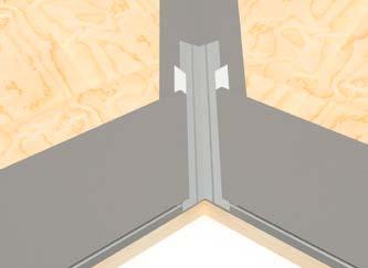
Openings at hips, ridges and head walls including chimneys, skylights, solar panels, and down slope horizontal abutments shall be fitted with weather blocking material to keep water on the surface of the field tile. Other methods approved by local building official will be allowed. See TRI Alliance technical bulletin at tileroofing.org
NOTES:
1. For recommended underlayment and fastening, see Page 13, Table 1A, 1B & 1C.
2. Underlayment shall extend a minimum of 4" up vertical wood blocking or wall, and is suggested to extend above wall flashing.
3. Apron flashing or other roof-to-wall closure material is necessary at roof-to-wall intersections. Roof-to-wall/apron flashing should extend a minimum of 2" up vertical walls, and provide a minimum of 3" overlap/headlap onto tile. The apron flashing is required to be overlapped a minimum of 2" by sheet metal counter flashing or wall cladding.
4. Dimensions shown are minimums and are intended to be approximate to all for reasonable tolerances due to field conditions.
5. The bottom edge of the counter flashing height settings shall be set above the roof deck a minimum of 4" for flat tile, 5" for low profile and 6" for high profile tile.
6. All metal flashing shall be a minimum of (No. 26 galvanized sheet metal) not less than 0.019 inch corrosion resistant metal (G90). See Table A for additional options.
7. Solid wood blocking is required behind Z-metal counter flashing applications.
Drawing
FRAMING MEMBER
ROOF-TO-WALL OR APRON FLASHING (HEMMED EDGE RECOMMENDED)
WALL VAPOR RETARDER OR CLADDING UNDERLAYMENT
EXTERIOR WALL CLADDING ABOVE TILE SURFACE
NOTE:
WEATHER BLOCKING REQUIRED WHEN PROFILED TILE INSTALLED (BETWEEN TILE AND FLASHING)
BATTEN WHERE REQUIRED
Openings at hips,ridges and head walls including chimneys, skylights, solar panels, and down slope horizontal abutments shall be fitted with weather blocking material to keep water on the surface of the field tile. Other methods approved by local building official will be allowed. See TRI Alliance technical bulletin at www.tileroofing.org
NOTES:
1. For recommended underlayment and fastening, see Page 13, Table 1A, 1B & 1C.
2. Underlayment shall extend a minimum of 4" up vertical wood blocking or wall, and is suggested to extend above wall flashing.
3. Apron flashing or other roof-to-wall closure material is necessary at roof-to-wall intersections. Roof-to-wall/apron flashing should extend a minimum of 2" up vertical walls, and provide a minimum of 3" overlap/headlap onto tile. The apron flashing is required to be overlapped a minimum of 2" by sheet metal counter flashing or wall cladding.
4. Dimensions shown are minimums and are intended to be approximate to all for reasonable tolerances due to field conditions.
5. The bottom edge of the counter flashing height settings shall be set above the roof deck a minimum of 4" for flat tile, 5" for low profile and 6" for high profile tile.
6. All metal flashing shall be a minimum of (No. 26 galvanized sheet metal) not less than 0.019 inch corrosion resistant metal (G90). See Table A for additional options.
Flashing (Z-Bar)
WALL VAPOR RETARDER OR CLADDING UNDERLAYMENT
FRAMING MEMBER
COUNTER FLASHING Z-BAR (SLOPED FOR POSITIVE DRAINAGE. SEE NOTE 6)
REQUIRED VERTICAL WOOD BLOCKING
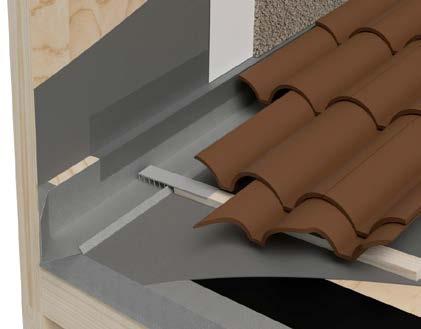
SHEET METAL PAN OR CHANNEL FLASHING (AT EAVE EXTEND 1" - 2" PAST EAVE CUT, TUCK, SEAL AND/OR SOLDER UNDER THE PAN TO DIVERT WATER AWAY FROM WALL)
KICKOUT
EXTERIOR WALL CLADDING
BATTEN EXTENSION OPTIONAL
OPTION: SEPARATOR PLY OR SHEET NO 15 ASPHALT-SATURATED FELT OR OTHER APPROVED MATERIAL
BATTEN WHERE REQUIRED
NOTES:
1. For recommended underlayment and fastening, see Page 13, Table 1A, 1B & 1C.
2. Underlayment shall extend a minimum of 4" up vertical wood blocking or wall.
3. Sheet metal pan flashing shall extend a minimum of 4" up the vertical wall approximately 6" out over the deck and have a minimum 3/4" return upward.
4. Solid wood blocking is required behind pan flashing and Z-metal counter flashing. Z metal or other counter flashing shall overlap vertical flange or pan or channel flashing by approximately 2" or greater.
5. At terminating tile, cut head lugs where they would otherwise create a damming condition or drainage impairment. Use a roof tile adhesive approved by the local building official or use wire ties or batten extender to secure tile.
6. Dimensions shown are minimums and are intended to be approximate to all for reasonable tolerances due to field conditions.
7. All metal flashing shall be a minimum of (No. 26 galvanized sheet metal) not less than 0.019 inch corrosion resistant metal (G90).
8. See Table A for additional options.
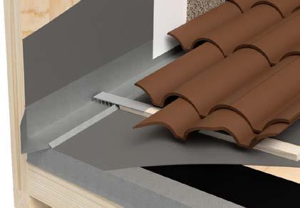
Where Wall Extends Past Eave
WEATHER RESISTIVE BARRIER (WRB) OR CLADDING UNDERLAYMENT
EXTERIOR WALL CLADDING MIN 1" ABOVE FLASHING
FRAMING MEMBER
BATTEN EXTENSION (OPTIONAL)
SHEET METAL PAN OR CHANNEL FLASHING (AT EAVE EXTEND 1" - 2" PAST EAVE CUT, TUCK, SEAL AND/OR SOLDER UNDER THE PAN TO DIVERT WATER AWAY FROM WALL)
KICKOUT
MINIMUM PAN FLASHING 6" MIN 4" MIN 3/4"MIN
UNDERLAYMENT
OPTION: SEPARATOR PLY OR SHEET NO 15 ASPHALT-SATURATED FELT OR OTHER APPROVED MATERIAL
BATTEN WHERE REQUIRED
BUILDING WRAP
SIDING MATERIAL
TILE
BATTEN EXTENSIONS FLASHING
NOTES:
1. For recommended underlayment and fastening, see Page 13, Table 1A, 1B & 1C.
2. Underlayment shall extend a minimum of 4" up vertical wood blocking or wall.
3. Sheet metal pan flashing shall extend a minimum of 4" up the vertical wall approximately 6" out over the deck and have a minimum 3/4" return upward.
4. Solid wood blocking is required behind pan flashing and Z-metal counter flashing. Z metal or other counter flashing shall overlap vertical flange or pan or channel flashing by approximately 2" or greater.
5. At terminating tile, cut head lugs where they would otherwise create a damming condition or drainage impairment. Use a roof tile adhesive approved by the local building official or sue wire ties or batten extender to secure tile.
6. Dimensions shown are minimums and are intended to be approximate to all for reasonable tolerances due to field conditions.
7. All metal flashing shall be a minimum of (No. 26 galvanized sheet metal) not less than 0.019 inch corrosion resistant metal (G90).
8. See Table A for additional options.

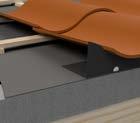
CUT OPEN OR CLOSED (Batten extension recommended)
NOTES:
1. These pictures show options that are found in the field at this time; other designs that will handle anticipated water flows may be used upon submissions of supporting data indicating anticipated water flows are equivalent to the code requirements as approved by local building official.
2. Valley metals shall extend 11" each way in compliance with International Building Code (IBC) section 1507.3.9, International Residential Code (IRC) R905.3.8 and the Uniform Building Code (UBC) section 1508.4 unless approved by the local building official.
3. Tile valleys may be cut open or closed.
4. When flat profile tile is installed “Closed Valley” a ribbed valley metal or single crown valley metal with a batten extension shall be used. Valley metals shall conform to IBC section 1507.3.9, IRC R905.3.8 and UBC section 1508.4
5. Dimensions shown are minimums and are intended to be approximate to all for reasonable tolerances due to field conditions.
6. All metal flashing shall be a minimum of (No. 26 galvanized sheet metal) not less than 0.019 inch corrosion resistant metal (G90).
7. See Table A for additional options.
WALL CLADDING
BUILDING WRAP
COUNTER FLASHING Z-BAR
PAN FLASHING
NAILER (OPTIONAL)* SECURELY FASTEN TO DECK
UNDERLAYMENT
* NOTE: TILES TO BE INSTALLED IN SUCH A FASHION AS TO PREVENT WATER DIVERSION OR BLOCKAGE FOR RECOMMENDED UNDERLAYMENT AND FASTENING REQUIREMENTS, SEE TABLE 1A AND TABLE 1B
“S-TILE”
WALL CLADDING COUNTER FLASHING
PAN FLASHING—6" MIN (Extend under Counter Flashing) FASTENER
UNDERLAYMENT ROOF DECK
NAILER (OPTIONAL—SECURELY FASTEN TO DECK)
NOTES:
WALL CLADDING COUNTER FLASHING
PAN FLASHING—6" MIN (Extend under Counter Flashing) FASTENER
UNDERLAYMENT ROOF DECK
1. Underlayment should extend a minimum of 4" up vertical wood blocking or wall.
2. See MC-12B for additional flashing details.
OPTIONAL FASTENER LOCATION IN THE PAN
WALL CLADDING
BUILDING WRAP
COUNTER FLASHING
BARREL TILE
PAN FLASHING
UNDERLAYMENT
NAILER (OPTIONAL)* SECURELY FASTEN TO DECK
* NOTE: TILES TO BE INSTALLED IN SUCH A FASHION AS TO PREVENT WATER DIVERSION OR BLOCKAGE FOR RECOMMENDED UNDERLAYMENT AND FASTENING REQUIREMENTS, SEE TABLE 1A, 1B AND 1C
WALL CLADDING COUNTER FLASHING
PAN FLASHING—6" MIN
(Extend under Counter Flashing) FASTENERS
UNDERLAYMENT ROOF DECK
WALL CLADDING COUNTER FLASHING
PAN FLASHING—6" MIN
(Extend under Counter Flashing) FASTENER
UNDERLAYMENT ROOF DECK
NAILER (OPTIONAL—SECURELY FASTEN TO DECK)
NOTES:
1. Underlayment should extend a minimum of 4" up vertical wood blocking or wall.
2. See MC-12B for additional flashing details.
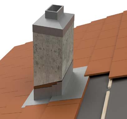
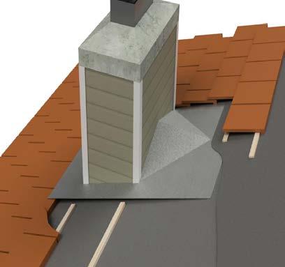
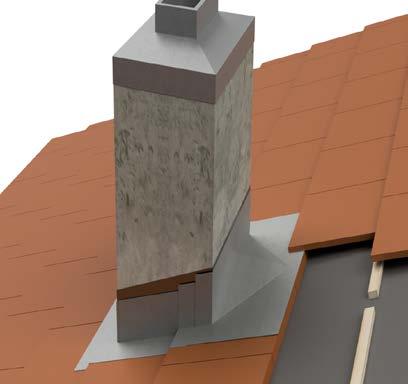
Chimney Or Other Penetrations 30" Or Less In Width
NOTE: WHERE DEBRIS CAN ACCUMULATE, SEE STEP FLASHING OPTION “MC-14A”
APRON FLASHING WITH WEATHER BLOCKING FOR PROFILED TILES
CHIMNEY OR PAN FLASHING (Must transition smoothly onto top of the tile through the tile head lap)
NOTE: Apron to be of sufficient length to provide a min. 3" lap onto tile 4" MIN
APRON FLASHING
NOTES:
WHERE DEBRIS CAN ACCUMULATE SEE STEP FLASHING OPTION “MC-14A”
COUNTER FLASHING
BACK SADDLE FLASHING
TILE TO BE HELD BACK FROM UPSLOPE OF CHIMNEY, SO NOT TO IMPAIR RUN OFF (Space or gap suggested to be 4"-6")
OPTIONAL 2" WIDE METAL CLIPS (Fasteners should not penetrate metal flashing)
BATTEN WHERE REQUIRED
OR CHANNEL
1. Chimney flashing dimensions may vary according to local weather conditions, chimney size, chimney location, slope of roof, rafter length behind chimney and tributary water area.
2. A backer or saddle flashing may be used for chimneys and other penetrations 30" or less in width. Extend a minimum 6" up chimney.
3. A diverter or cricket flashing recommended for chimneys and other penetrations equal to or greater than 30" in width promote positive runoff.
4. Dimensions shown are minimums and are intended to be approximate to all for reasonable tolerances due to field conditions.
5. Flashing must be securely fastened to chimney or sidewall flashing.
6. Underlayment must turn up chimney wall a minimum of 4".
7. All chimney flashing shall be a minimum of (No. 26 galvanized sheet metal) not less than 0.019 inch corrosion resistant metal (G90).
8. See Table A for additional options.
COUNTER FLASHING (THROUGH-WALL OR INSET-TYPE FLASHING OPTION)
BACKER/SADDLE FLASHING
STEP FLASHING OVER TILE (MALLEABLE FOR PROFILE TILES) EXTENDED 4" ONTO TILE SURFACE OR 1" PAST CROWN ON PROFILE TILE, WHICHEVER IS GREATER
APRON FLASHING WITH WEATHER BLOCKING FOR PROFILED TILE
NOTE: Apron to be of sufficient length to provide a min. 3" lap onto tile
APRON FLASHING STEP FLASHING
NOTES:
1. Chimney flashing dimensions may vary according to local weather conditions, chimney size, chimney location, slope of roof, rafter length behind chimney and tributary water area.
2. A backer or saddle flashing may be used for chimneys and other penetrations 30" or less in width. Extend a minimum 6" up chimney.
3. A diverter or cricket flashing recommended for chimneys and other penetrations equal to or greater than 30" in width promote positive runoff.
4. Dimensions shown are minimums and are intended to be approximate to all for reasonable tolerances due to field conditions.
5. Flashing must be securely fastened to chimney or sidewall flashing.
6. Underlayment must turn up chimney wall a minimum of 4".
7. All chimney flashing shall be a minimum of (No. 26 galvanized sheet metal) not less than 0.019 inch corrosion resistant metal (G90).
8. See Table A for additional options.
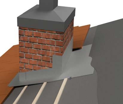
Chimney Or Other Penetrations Greater Than 30" Wide
CRICKET MAY BE COVERED WITH AN APPROVED SEALED SYSTEM IN ACCORDANCE WITH LOW-SLOPE ROOFING REQUIREMENTS
CRICKET FLASHING (EXTEND UPPER END OF FLASHING 6" MIN BEYOND FIRST COURSE OF OVERLAYING TILE)
MIN 2" ABOVE APEX
CRICKET METAL FLASHING WITH OPTIONAL HEM
CHANNEL OR PAN FLASHING
APRON FLASHING WITH WEATHER BLOCKING FOR PROFILED TILES
NOTE: Apron to be of sufficient length to provide a min. 3" lap onto tile
APRON FLASHING
NOTES:
OR CHANNEL FLASHING
1. Chimney flashing dimensions may vary according to local weather conditions, chimney size, chimney location, slope of roof, rafter length behind chimney and tributary water area.
2. A backer or saddle flashing may be used for chimneys and other penetrations 30"or less in width.
3. Extend a minimum 6" up chimney.
4. A diverter or cricket flashing recommended for chimneys and other penetrations greater than 30" in width promote positive runoff.
5. Dimensions shown are minimums and are intended to be approximate to all for reasonable tolerances due to field conditions.
6. Underlayment must turn up chimney wall a minimum of 4".
7. All chimney flashing shall be a minimum of (No. 26 galvanized sheet metal) not less than 0.019 inch corrosion resistant metal (G90).
8. See Table A for additional options.
Chimney Or Other Penetrations Greater Than 30" Wide
CRICKET FLASHING (EXTEND UPPER END OF FLASHING 6" MIN . BEYOND FIRST COURSE OF OVERLAYING TILE)
COUNTER FLASHING
CRICKET METAL FLASHING WITH OPTIONAL HEM
STEP FLASHING OVER TILE
APRON FLASHING
NOTE: Apron to be of sufficient length to provide a min. 3" lap onto tile
MIN APRON FLASHING
NOTES:
1. Chimney flashing dimensions may vary according to local weather conditions, chimney size, chimney location, slope of roof, rafter length behind chimney and tributary water area.
2. A backer or saddle flashing may be used for chimneys and other penetrations 30" or less in width.
3. Extend a minimum 6" up chimney.
4. A diverter or cricket flashing recommended for chimneys and other penetrations greater than 30" in width promote positive runoff.
5. Dimensions shown are minimums and are intended to be approximate to all for reasonable tolerances due to field conditions.
6. Underlayment must turn up chimney wall a minimum of 4"
7. All chimney flashing shall be a minimum of (No. 26 galvanized sheet metal) not less than 0.019 inch corrosion resistant metal (G).
8. See Table A for additional options.
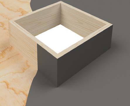
ROOF SLOPE
CURB—HEIGHT TO BE MINIMUM 2" X 6" (NOMINAL) OR HIGHER TO ALLOW FOR PROPER FLASHING HEIGHT
UNDERLAYMENT—FELT SHOULD TURN UP TO THE TOP OR OVER THE TOP OF CURB
ALL CORNERS TO SEALED WITH ASPHALT ROOF CEMENT, MEMBRANE COMPATIBLE SEALANT OR CODE APPROVED MATERIAL ROOF DECK
NOTES:
1. For recommended underlayment and flashing requirements, see page 13 TABLE 1A, 1B and 1C.
2. Dimensions shown are minimums and are intended to be approximate to all for reasonable tolerances due to field conditions.
3. A backer or saddle flashing may be used for curbed penetrations, depending upon width or curb.
4. Extend flashings a minimum of 6" up curb.
Typical Curb Skylight Opening
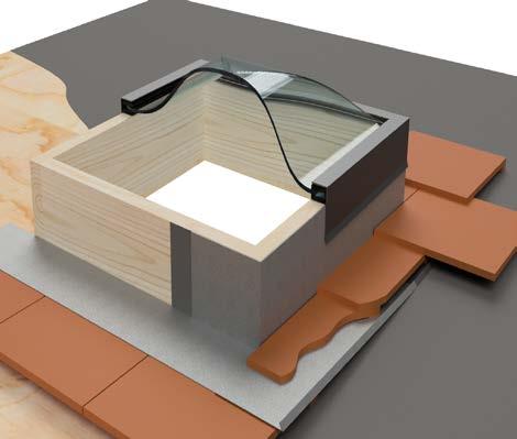
NOTE: WHERE DEBRIS CAN ACCUMULATE, SEE STEP FLASHING OPTIONS “MC-16B”
SADDLE OR CRICKET FLASHING BIBBED OR SEALED WITH THREE COURSE APPLICATION
TILE TO BEHELD BACK FROM UPSLOPE CURB OF SKYLIGHT, SO NOT TO IMPAIR RUN OFF
APRON FLASHING OF SUFFICIENT LENGTH TO PROVIDE 3" MIN LAP ONTO TILE
PAN OR CHANNEL FLASHING BATTENS WHERE REQUIRED
NOTES:
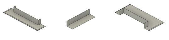
OPTIONAL HEMMED EDGES FORMED FLASHING WITH SOLDERED OR SEALED CORNERS
APRON FLASHING
PAN OR CHANNEL FLASHING
SADDLE/BACKER FLASHING
1. Skylight flashing dimensions may vary according to local weather conditions, skylight size, location, slope of roof, rafter length behind skylight and tributary water area.
2. A backer or saddle flashing may be used for skylights and other penetrations 30" or less in width.
3. Extend a minimum 6" up chimney.
4. A diverter or cricket flashing recommended for skylights and other penetrations greater than 30" in width promote positive runoff.
5. Dimensions shown are minimums and are intended to be approximate to all for reasonable tolerances due to field conditions.
6. Underlayment must turn up chimney wall a minimum of 4"
7. All skylight flashing shall be a minimum of (No. 26 galvanized sheet metal) not less than 0.019 inch corrosion resistant metal (G90).
8. See Table A for additional options.
Typical Curb Skylight Opening
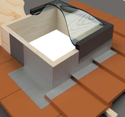
CURB HEIGHT TO BE A MINIMUM 2"X8" (NOMINAL) OR HIGHER TO ALLOW FOR STEP FLASHINGS
SADDLE OR CRICKET FLASHING
TILE TO BE HELD BACK FROM UP SLOPE CURB OF SKYLIGHT, SO AS NOT TO IMPAIR RUN OFF
STEP FLASHING (MALLEABLE FOR PROFILE TILE)
APRON FLASHING
UNDERLAYMENT
NOTES:
OPTIONAL HEMMED EDGES FORMED FLASHING WITH SOLDERED OR SEALED CORNERS
APRON FLASHING
PAN OR CHANNEL FLASHING
SADDLE/BACKER FLASHING
1. Skylight flashing dimensions may vary according to local weather conditions, skylight size, location, slope of roof, rafter length behind skylight and tributary water area.
2. A backer or saddle flashing may be used for skylights and other penetrations 30" or less in width.
3. Extend a minimum 6" up chimney.
4. A diverter or cricket flashing recommended for skylights and other penetrations greater than 30" in width promote positive runoff.
5. Dimensions shown are minimums and are intended to be approximate to all for reasonable tolerances due to field conditions.
6. Underlayment must turn up chimney wall a minimum of 4"
7. All skylight flashing shall be a minimum of (No. 26 galvanized sheet metal) not less than 0.019 inch corrosion resistant metal (G90).
8. See Table A for additional options.
FIELD TILE
VALLEY METAL
NOTE: Lap Valley Joint 6" min (Blindnail each section of valley metal along its upper end when using clips.
OPTIONAL NAILS OR METAL CLIP . NAILS USED AT THE EDGE OF THE METAL SHOULD BE SEALED
UNDERLAYMENT
Tile Installed With Gap At Center Of Valley
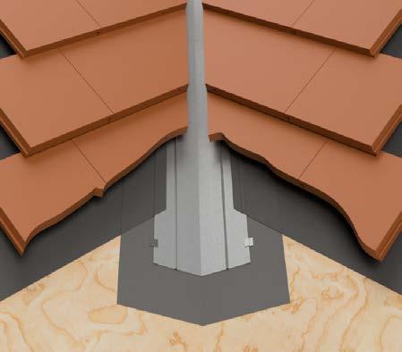
NOTE: Tile at valley may be cut to form closed or open metal valley detail. When flat profiled tile is installed as “closed valley” a ribbed metal or single crown valley metal with a batten extension shall be used. When using standing hem flashing, use woven underlayment method. See MC-03 and MC-17B
NOTES:
1. For recommended underlayment and fastening, see Page 13, Table 1A, 1B & 1C
2. Cut tile pieces should be secured by one or a combination of the following: (a) code approved adhesive; (b) wire ties; (c) batten extensions; (d) cut tile clip or (e) other code approved fastening devices.
3. Metal valley flashing shall be a minimum of (No. 26 galvanized sheet metal) not less than 0.019 inch corrosion resistant metal (G90). See Table A for additional options.
4. Other valley metal profiles are available. See MC-12B for examples.
5. The tile must extend a minimum of 4" over the valley metal.
6. Dimensions shown are minimums and are intended to be approximate to all for reasonable tolerances due to field conditions.
7. Valley metals should be designed to suit climate area, control water runoff, and discharge expected water flows.
On Counter Batten Installations
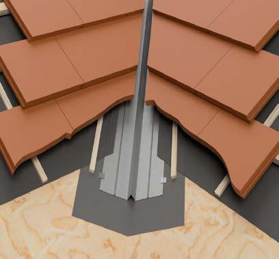
OPTIONAL HORIZONTAL BATTENS (REQUIRED IF VERTICAL BATTENS USED) NOT SHOWN
OPTIONAL VERTICAL BATTENS INSTALLED UNDER HORIZONTAL BATTENS
FIELD TILE
VALLEY METAL
NOTE: Lap Valley Joint 6" min (Blind-nail each section of valley metal along its upper end when using clips.
OPTIONAL NAILS OR METAL CLIP NAILS USED AT THE EDGE OF THE METAL SHOULD BE SEALED
UNDERLAYMENT
Notes:
1. For recommended underlayment and fastening, see Page 13, Table 1A, 1B & 1C
2. Cut tile pieces should be secured by one or a combination of the following: (a) code approved adhesive; (b) wire ties; (c) batten extensions; (d) cut tile clip or (e) other code approved fastening devices.
3. Metal valley flashing shall be a minimum of (No. 26 galvanized sheet metal) not less than 0.019 inch corrosion resistant metal (G90). See Table A for additional options.
4. Other valley metal profiles are available. See MC-12B for examples.
5. The tile must extend a minimum of 4" over the valley metal.
6. Dimensions shown are minimums and are intended to be approximate to all for reasonable tolerances due to field conditions.
7. Valley metals should be designed to suit climate area, control water runoff, and discharge expected water flows.
FIELD TILE
VALLEY METAL
NOTE: Lap Valley Joint 6" min (Blind-nail each section of valley metal along its upper end when using clips.
OPTIONAL BATTEN EXTENDER
OPTIONAL 1½" WIDE METAL CLIP (ATTACH AT EACH HORIZONTAL BATTEN)
OPTION 2 (NOT SHOWN) HORIZONTAL BATTEN UNDER METAL
UNDERLAYMENT
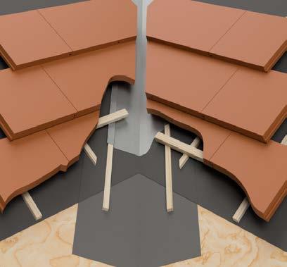
NOTE: VALLEY METAL SHALL EXTEND AT LEAST 11" FROM CENTER LINE EACH WAY AND SHALL HAVE A SPLASH DIVERTER RIB OF NOT LESS THAN 1" HIGH AT THE FLOW LINE FORMED AS PART OF THE FLASHING OTHER DESIGNS THAT WILL HANDLE ANTICIPATED WATER FLOWS MAY BE USED UPON SUBMISSION OF SUPPORTING DATA INDICATING THAT ANTICIPATED WATER FLOWS ARE EQUIVALENT TO THE CODE REQUIREMENTS
Notes:
1. For recommended underlayment and fastening, see Page 13, Table 1A, 1B & 1C
2. Cut tile pieces should be secured by one or a combination of the following: (a) code approved adhesive; (b) wire ties; (c) batten extensions; (d) cut tile clip or (e) other code approved fastening devices.
3. Metal valley flashing shall be a minimum of (No. 26 galvanized sheet metal) not less than 0.019 inch corrosion resistant metal (G90). See Table A for additional options.
4. Valley flashings shall extend at least 11" from centerline each way and have a splash diverter rib not less than 1" high at flow line formed as part of the flashing. On projects with large expansive roof areas/or long rafter lengths, wider metal is required. Tile shall extend of the valley into valley trough a minimum of 1½"
5. Other valley metal profiles are available. See MC-12B for examples.
6. The tile must extend a minimum of 4" over the valley metal.
7. Dimensions shown are minimums and are intended to be approximate to all for reasonable tolerances due to field conditions.
8. Valley metals should be designed to suit climate area, control water runoff, and discharge expected water flows.

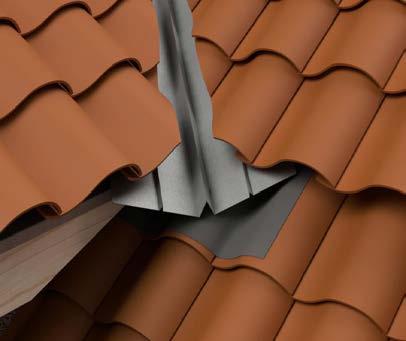
EXAMPLE OF FLAT OR LOW PROFILE TILE
THE VALLEY METAL MUST LAP ONTO THE TILE OF THE COURSE BELOW THE ROOF TRANSITION FLASHING
EXAMPLE FOR HIGH PROFILE TILE
THE VALLEY METAL MUST LAP ONTO THE TILE OF THE COURSE BELOW THE ROOF TRANSITION FLASHING
LEAD SOAKER OR OTHER MALLEABLE MATERIAL SHOULD BE USED TO FORM A WATER FLOW TRANSITION FLASHING
VALLEY
(OPTIONAL V-CUT DEPICTED AT END OF VALLEY METAL)
OPTIONAL COUNTER FLASHING (EXTEND OVER STEP FLASHING)
STEP FLASHING
EXTERIOR WALL CLADDING (OVER WEATHER RESISTIVE BARRIER (WRB) BY OTHERS
HEAD WALL OR APRON FLASHING
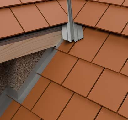
SURFACE MOUNT FLASHING
WALL CLADDING
SEALANT
CAULKING “LIP” GASKET FASTENER
SURFACE MOUNTED COUNTER FLASHING FLASHING
UNDERLAYMENT ROOF DECK
STEP FLASHING
WEATHER RESISTIVE BARRIER (WRB) OR WALL CLADDING UNDERLAYMENT
WALL CLADDING/SIDING
NOTES:
1. Surface-mounted flashing may be sufficient in some mild climates. However concealed or insert flashing such as “Z” metal or stucco-type two piece reglet and counter flashing or step flashing, are recommended in wet climates, particularly with stucco or other permeable cladding systems.
2. Dimensions shown are minimums and are intended to be approximate to all for reasonable tolerances due to field conditions.
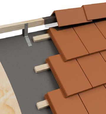
TRIM TILE
APPROVED WEATHER BLOCKING
FIELD TILE
ROOF DECK
Notes:
1. For recommended underlayment and fastening, see Page 13, Table 1A, 1B & 1C.
2. All hip and ridge tile are required to have code approved adhesive between laps of trim tile to cover nail hole and create a bond between trim tiles.
3. Tile to be cut in a manner to properly conform to method of weather blocking material used.
4. Battens for tiles with protruding anchor lugs are optional for slopes between 3:12 and 7:12. Direct deck attachment of tile as approved by local building official.
5. Dimensions shown are minimums and are intended to be at proximate to all for reasonable tolerances due to field conditions.
6. Orientation and termination of ridge tiles may vary.
CODE APPROVED ADHESIVE OVER MECHANICAL ATTACHMENT (SEE BELOW)
TRIM TILES
RIDGE/HIP NAILER OF SUFFICIENT HEIGHT TO MAINTAIN AN EVEN PLANE OF UNDERLAYMENT
RIDGE RISER; HEAVY GAUGE GALVANIZED STEEL OR OTHER METAL, SECURELY FASTENED PER BRACKET MANUFACTURER INSTRUCTIONS
FIELD TILES
UNDERLAYMENT
NOTE: Overhangs at hips, ridges and headwalls including chimneys, skylights, solar panels, and downslope horizontal abutments shall be fitted with weather blocking material to keep water on the surface of the field tile. Other materials approved by the local building official will be allowed. Wrapping of nailer board is optional except with the use of mortar. (All tile profiles)
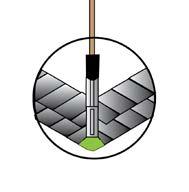
HIP STARTER OR OTHER CLOSURE MATERIAL
HIP AND NAILER
HIPS TO BE SEALED WITH UV RESISTANT MATERIAL, MORTAR ROOF CEMENT, PREFORMED PLASTIC OR SELF ADHERING FLASHING WHERE TILE MEETS HIP BOARD
ROOFERS CEMENT OR TILE ADHESIVE MUST BE APPLIED AT HEADLAP TO COVER NAIL HOLE
HEADLAP TO COVER NAIL HOLE PROVIDE HEADLAP
HOLD BACK HIP NAILER FROM EAVE EDGE
CODE APPROVED ADHESIVE OVER MECHANICAL ATTACHMENT
RIDGE TILE
WEATHER BLOCKING MORTAR OR OTHER APPROVED MATERIALS
WRAP NAILER IF USING MORTAR
SECURELY FASTEN RIDGE/HIP NAILER OF SUFFICIENT HEIGHT TO MAINTAIN AN EVEN PLANE OF TRIM TILES
UNDERLAYMENT
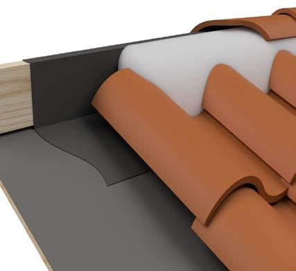
NOTE: Openings at hips,ridges and head walls including chimneys, skylights, solar panels, and down slope horizontal abutments shall be fitted with weather blocking material to keep water on the surface of the field tile. Other methods approved by local building official will be allowed. See TRI Alliance technical bulletin at www.tileroofing.org Wrapping of nailer board is required with the use of mortar (All profiles).
Notes:
1. For recommended underlayment and fastening, see Page 13, Table 1A, 1B & 1C.
2. All hip and ridge tile are required to have code approved adhesive between laps of trim tile to cover nail hole and create a bond between trim tiles.
3. Tile to be cut in a manner to properly conform to method of weather blocking material used.
4. Battens for tiles with protruding anchor lugs are optional for slopes between 3:12 and 7:12. Direct deck attachment of tile as approved by local building official.
5. Dimensions shown are minimums and are intended to be approximate to all for reasonable tolerances due to field conditions.
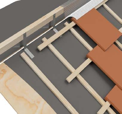
TRIM TILE
APPROVED VENTILATION MATERIAL
FIELD TILE
ROOF DECK
WIDE CONTINUOUS VENTILATION OPENING
VENTILATION MATERIAL
RIDGE RISER BRACKET: HEAVY GALVANIZED STEEL, OR OTHER METAL SECURELY FASTEN PER BRACKET MANUFACTURER INSTRUCTIONS
RIDGE/HIP NAILER OF SUFFICIENT HEIGHT TO MAINTAIN AN EVEN PLANE OF TRIM TILES
CONTINUOUS 1" WIDE VENTILATION SLOT (MAY REQUIRE ADDITIONAL SEISMIC CONSIDERATION IN CERTAIN AREAS CHECK WITH LOCAL BUILDING OFFICIALS)
BATTENS WHERE REQUIRED
COUNTER BATTENS WHERE REQUIRED NOMINAL 1" X 2"
UNDERLAYMENT
NOTES:
1. Refer to vent manufacturer instructions for products and limitations.
2. Ensure the vent material/weather blocking and/or ridge tile will provide sufficient coverage over field tile, if top course is held down from ridge to allow for ventilation, cut out slot in sheathing.
3. For recommended underlayment and fastening, see Page 13, Table 1A, 1B & 1C.
4. Dimensions shown are minimums and are intended to be approximate to all for reasonable tolerances due to field conditions.
TRIM TILES COVERS FIELD TILE WEATHER BLOCKING
FIELD TILE UNDERLAYMENT
CAP CONDITION
UNDERLAYMENT EXTENDS OVER TRIM NAILER
STANDARD METAL FLASHING CLEAT WAY BE OPTIMAL DEPENDING UPON FLASHING’S FACE DIMENSIONS
METAL CAP COVERS FIELD TILE MIN OF 4"
UNDERLAYMENT/WEATHER BLOCK CARRIED OVER TOP OF WALL
OPTIONAL SECOND LAYER OF WEATHER BLOCK COVERING TOP 3" OF FIELD TILE AND FASTENED TO TOP OF WALL
NOTES:
1. For recommended underlayment and fastening, see Page 13, Table 1A , 1B & 1C.
2. Dimensions shown are minimums and are intended to be approximate to all for reasonable tolerances due to field conditions.
See Drawing MC-12B For Additional Flashing Information
MIN 2" MIN
6" PAN DIMENSION WILL VARY BASED UPON EXPECTED WATER FLOW & DEPTH OF FLASHING . TYPICAL FOR DETAILS
75"–1 5" TYPICAL RANGE 6" MIN
75"–1 5" TYPICAL RANGE 6" MIN
75"–1 5" TYPICAL RANGE
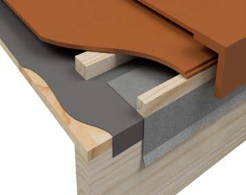
OPTIONAL CLEAT DRIP EDGE
UNDERLAYMENT EXTENSION OPTIONAL
75" MIN ENGAGE CLEAT DRIP EDGE
NOTES:
1. Flashing details may vary according to local weather conditions, roof size, location, slope of roof and contributory run-off area.
2. Underlayment shall extend a minimum of 4" up vertical wood blocking, wall, or top of fascia or gable trim.
3. Sheet metal flashing shall be a minimum of (No. 26 galvanized sheet metal) not less than 0.019 inch corrosion resistant metal (G90). See Table A for additional options.
4. Dimensions shown are minimums and are intended to be approximate to all for reasonable tolerances due to field conditions.
5. Rake flashing and wood nailer/trim board shall be raised above roof deck to a height greater than the height of the installed roof tile.
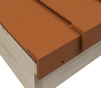
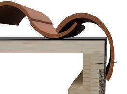
CONCRETE BARREL TRIM SHOULD BE ROLLED ONTO ROOF AS FAR AS POSSIBLE
EXTEND FELT OVER EDGE A MINIMUM OF 1"
OPTIONAL NAIL BOARD
BATTENS NOMINAL 1"X2" (WHERE REQUIRED)
STUCCO OR OTHER MATERIAL
FOR ADDITIONAL FASTENING IN REGIONS SUBJECT TO HIGH WINDS OR SNOW ACCUMULATIONS, A MINIMUM 1" DAB OF CODE APPROVED ADHESIVE IS RECOMMENDED AT UNDERSIDE OF OVERLAP
FACTORY-FINISHED BUTT END EXPOSED PLACE THICK END UPSLOPE TOWARDS RIDGE
CUT OFF HEAD END OF FIRST RAKE TILES SO FACTORY-FINISHED BUTT END IS FLUSH WITH EAVE COURSE TILES .
TWO CORROSION-RESISTANT FASTENERS, PER RAKE TILE, OF SUFFICIENT LENGTH TO PENETRATE THE 2X NAILER OR BARGE BOARD A MINIMUM OF 3/4" HEAD OF FASTENERS SHOULD BE LARGER THAN NAIL HOLE IN TRIM TILES
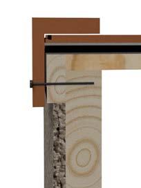
NOTES:
1. Dimensions shown are minimums and are intended to be approximate to all for reasonable tolerances due to field conditions.
2. Rake tiles must fastened into a minimum nominal 2" gable fascia or equivalent dimension.
3. The fasteners must penetrate a minimum of 3/4" into dimensional wood lumber.
4. See TABLE A for additional flashing instructions.
BIRD STOP
NOMINAL 2" X 3" OR 2" X 4" NAILER
UNDERLAYMENT (TURN DOWN OUTER EDGE 1")
NOMINAL 2" NAILER
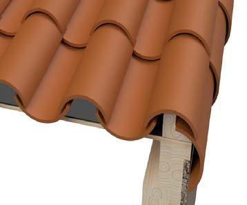
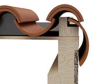
NOTES:
PAN TILE
TWO CORROSION-RESISTANT NAILS, PER RAKE TILE, OF SUFFICIENT LENGTH TO PENETRATE THE NAILER OR BARGE BOARD A MINIMUM OF 75"
STARTER COVER TILE
BOOSTER TILE
NAILER BOARD
OPTIONAL NAIL
EXTEND FELT OVER EDGE MINIMUM OF 1"
OPTIONAL NAIL BOARD
BIRD STOP
STUCCO OR OTHER CLADDING
1. Dimensions shown are minimums and are intended to be approximate to all for reasonable tolerances due to field conditions.
2. See TABLE A for additional flashing instructions.
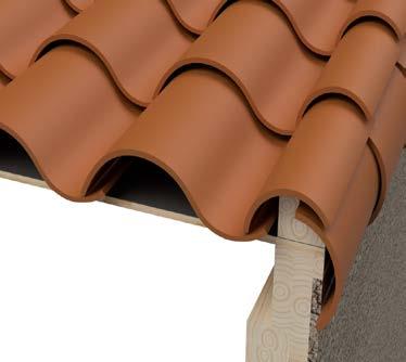
EAVE DRIP EDGE FLASHING NOT SHOWN FOR CLARITY
NOMINAL 2" X 3" OR 2" X 4" NAILER
NOMINAL 2" X 2" NAILER
UNDERLAYMENT
OPTIONAL: PAN OR STRAW NAIL
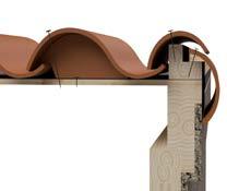
HIGH PROFILE TILE
CORROSION-RESISTANT FASTENERS PER RAKE TILE OF SUFFICIENT LENGTH TO PENETRATE THE NAILER OR BARGE BOARD A MINIMUM OF NAILER BOARD OR STRAW NAIL STARTER COVER
EXTEND FELT OVER EDGE MINIMUM OF OPTIONAL NAIL BOARD
BIRD STOP
STUCCO OR OTHER MATERIAL
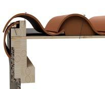
NOTES:
1. Dimensions shown are minimums and are intended to be approximate to all for reasonable tolerances due to field conditions.
Vents To Be Installed Per Vent Manufacturer Instructions
FIELD TILE
VENT HOOD TILE FLASHINGS
NOTCH OR OPEN NOSE OF TILE FOR DRAINAGE
ADHESIVE WEATHER BLOCKING (OVER TILE UNDER FLASHING)
DECK FLASHING, SEE NOTE 2 UNDERLAYMENT
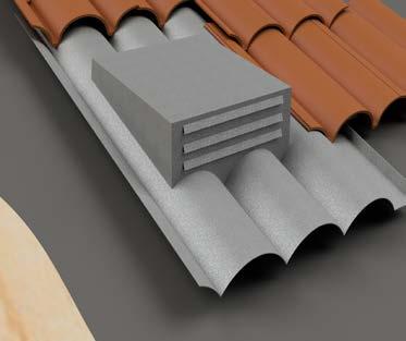
NOTE: CHECK LOCAL CODE REQUIREMENTS FOR VERMIN SCREENING
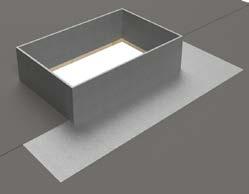
UNDERLAYMENT DETAIL AT DECK FLASHING
NOTES:
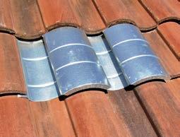
VENTED TILES AVAILABLE TO MATCH INDIVIDUAL TILE MANUFACTURER PROFILES
1. One layer of No. 30 asphalt-saturated felt complying with ASTM D226 Type II (ASTM D4869 Type IV) or approved equal is required as a minimum underlayment on all tile roof applications. Other underlayments as approved by local building officials will be allowed.
2. A secondary flashing, as depicted in the left inset, is required around penetrations to prevent moisture intrusion should water reach the
3. underlayment, under the roof tile. This secondary or deck flashing is required with all tiles.
4. For climates with wind driven rain or blowing snow, consult local building official for approved applications.
5. Metal flashing shall be a minimum of (No. 26 galvanized sheet metal) not less than 0.019 inch corrosion resistant metal (G90).
6. See Table A for additional options.
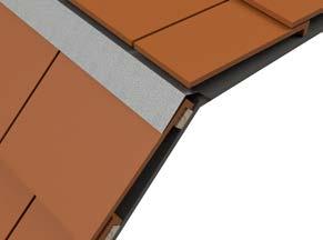

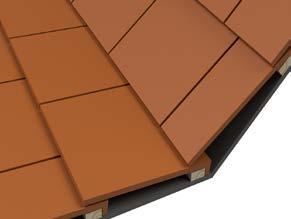
UNDERLAYMENT, SEALANT OR SEAL STRIP OVER TOP OF FLASHING
MALLEABLE FLASHING OR RIGID METAL WITH WEATHER BLOCKING FOR PROFILE TILES FOR FLAT TILES, PREFORMED, METAL, WITH HEMMED EDGE(S), MAY BE USED OVER BREAK FLASHING TO PROVIDE A SNUG FIT
FLASHING MUST LAP TILE 3" MINIMUM
BATTEN (WHERE REQUIRED)
UNDERLAYMENT
OPTION 1—WITH METAL TRANSITION FLASHING
UNDERLAYMENT, SEALANT OR SEAL STRIP OVER TOP OF FLASHING
MALLEABLE METAL FLASHING OR RIGID WEATHER BLOCKING FOR PROFILE TILES FOR FLAT TILES, PREFORMED ,METAL, WITH HEMMED EDGE(S), MAY BE USED OVER BREAK FLASHING TO PROVIDE A SNUG FIT
3" MIN .
BATTEN WHERE REQUIRED
UNDERLAYMENT
INCREASE HEADLAP OR PROVIDE WEATHER BLOCKING TO STOP BACK FLOW OF WATER AT TRANSITION SEAL AS REQUIRED
BATTEN WHERE REQUIRED
UNDERLAYMENT
NOTES:
1. One layer of No. 30 asphalt-saturated felt complying with ASTM D226 Type II (ASTM D4869 Type IV) or approved equal is required as a minimum underlayment on all tile roof applications. Other underlayments as approved by local building officials will be allowed.
2. Dimensions shown are minimums and are intended to be approximate to all for reasonable tolerances due to field conditions.
ROOF TILE
TILE EXTENDS OVER BACK EDGE OF GUTTER FACE
PLANE OF TILE TO BE ABOVE OUTER EDGE OF GUTTER
DRIP EDGE FLASHING GUTTER
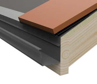
Optional Recessed First Course For Ice Damming
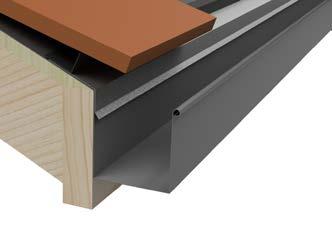
FIRST COURSE HELD BACK FROM FASCIA EDGE FOR REDUCING ICE DAMMING POTENTIAL
NOTES:
1. For recommended underlayment and fastening, see Page 13, Table 1A, 1B & 1C.
NOTES: This drawing is included to show one style of gutter installation since gutter conditions vary by climate conditions. Please contact your local gutter manufacturer for specific installation requirements.
2. An eave drip flashing is required with stucco fascia, EIFS (Exterior Insulated Finish System) and flush fascia perimeter edges.
3. Battens for tile with projecting anchor lugs are optional for slopes between 3:12 less than or equal to 7:12. Direct deck nailing requirements may be permissible.
4. Eave closures should be the height equal to combined thickness of batten system and thickness of one course of tile.
5. Dimensions shown are minimums and are intended to be approximate to all for reasonable tolerances due to field conditions.
When replacing an individual tile, one method is to remove the broken tile by breaking into smaller pieces with a hammer or other acceptable tool . This will minimize the disturbance of the surrounding tiles . Once the tile has been removed, any remaining fasteners should be removed and the resulting holes in the underlayment cleaned and patched
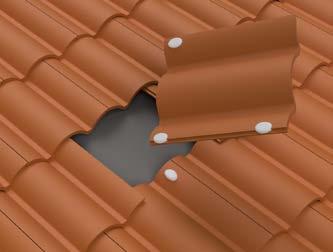
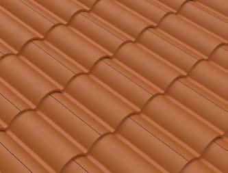
FOR APPLICATIONS WITHOUT BATTENS
YES (PROPER LOCATION)
NO (IMPROPER LOCATION)
TILE ADHESIVE (CODE APPROVED SEE PAGE 8)
WEDGE SURROUNDING TILES UP AND SLIDE TILE INTO PLACE (FOR SLOPES OVER 7:12—BATTENS REQUIRED)
REMOVE BROKEN TILE AND FASTENER WEDGE SURROUNDING TILES, APPLY CODE APPROVED ROOF TILE ADHESIVES AND SLIDE NEW TILE IN PLACE
TILE ADHESIVE (CODE APPROVED, SEE PAGE , UNDER THE TILE. NOT ON WATER CHANNEL
Note: The replacement tile may be slipped into place and fastened with an approved tile adhesive. It is important that the adhesive is placed in a position that will assure contact with adjacent tiles without affecting the flow of water. If adhesive is applied to interlocking water channel, it must be placed above the headlap to avoid water damming.
REMOVE ANY SHIM THAT HAD BEEN USED DURING THE REPAIR PROCESS AND ENSURE THAT TILES SURROUNDING THE REPLACED PIECE PROPERLY FIT AND ARE SEATED
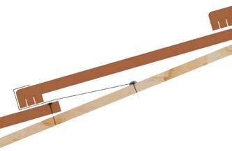
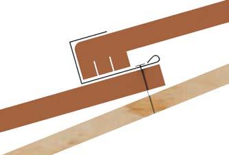
REPLACEMENT TILE
SEAL WITH MASTIC WIRE
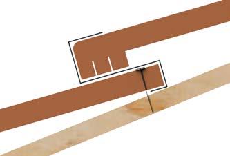
NOTES:
1. Clear area of debris where broken tile is to be placed. Remove fasteners from previous tile. Fasteners may be removed by using slate ripper or, in the case of screws a hacksaw blade.
2. Lift the nose of tile in course above. Then slide replacement tile, underneath the overlapping tile and over the hook, then slide tile into the hook and down the “L” hooks underneath top course of course below.
3. Adjust replacement tile to align or interlock (depending on the tile type) with tiles on either side.
4. Another method is to fasten a 12 gauge copper wire into the deck, replacing the tile and then bending the exposed wire. A sheet metal (e.g. copper) strip can also be applied.
5. Make adjustments for field tile.
Installation on Metal Deck—Considerations Ribs Running Parallel to Roof Slope
FOR INFORMATIONAL PURPOSES ONLY—THESE HAVE NOT BEEN EVALUATED BY UNIFORM ES.
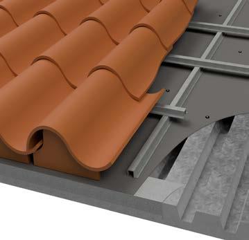
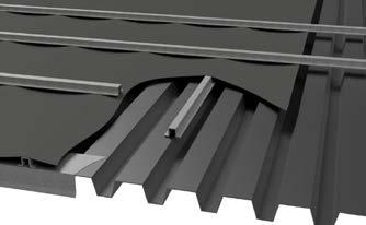
NOTES:
1. Vertical battens to be metal or as approved or designed as per metal deck manufacturer.
2. For recommended underlayment and fastening, see Page 13, Table 1A, 1B & 1C.
CODE APPROVED REINFORCED UNDERLAYMENT ATTACHED WITH MECHANICALLY DRIVEN CAPPED FASTENERS
TILE FASTENED TO BATTENS WITH SELF-TAPPING SCREWS OR OTHER CODE APPROVED FASTENERS
METAL BATTENS FASTENED TO METAL DECK WITH SCREWS OR OTHER CODE APPROVED FASTENERS
METAL DECK
EAVE RISER STRIP OR RAISED BIRD STOP AS DESIGNED
DRIP EDGE FLASHING
FOR FIRE-RATED SYSTEMS, ADDITIONAL COMPONENTS MAY BE REQUIRED.
The pre-engineered roof systems are included for informational purposes only and are not recognized under evaluation reports for roof tiles
3. An eave drip flashing is required with stucco fascia, EIFS (Exterior Insulated Finish System) and flush fascia perimeter edges.
4. Eave closures should be the height equal to combined thickness of batten system and thickness of one course of tile.
5. Dimensions shown are minimums and are intended to be approximate to all for reasonable tolerances due to field conditions.
Installation on Metal Deck—Considerations
Ribs Running Perpendicular To Roof Slope With Rigid Sheathing MC-25A
FOR INFORMATIONAL PURPOSES ONLY—THESE HAVE NOT BEEN EVALUATED BY UNIFORM ES.
LOW PROFILE MECHANICALLY DRIVEN CAPPED FASTENERS
TILE FASTENED TO BATTENS WITH SELF-TAPPING SCREWS OR WIRED IN PLACE
BATTENS FASTENED TO METAL DECK WITH SCREWS OR OTHER CODE APPROVED FASTENERS
SOLID SHEATHING TO RETAIN FASTENER AND SUPPORT UNDERLAYMENT MAY BE PLYWOOD OR NONCOMBUSTIBLE SUBSTRATE AS APPROVED BY BUILDING OFFICIAL
EAVE RISER STRIP OR RAISED BIRD STOP AS DESIGNED
DRIP EDGE FLASHING
METAL DECK FOR FIRE-RATED SYSTEMS, ADDITIONAL COMPONENTS MAY BE REQUIRED
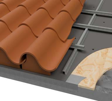
The pre-engineered roof systems are included for informational purposes only and are not recognized under evaluation reports for roof tiles
NOTES:
1. Vertical battens to be metal or as approved or designed as per metal deck manufacturer
2. For recommended underlayment and fastening, see Page 13, Table 1A, 1B & 1C
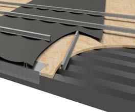
3. An eave drip flashing is required with stucco fascia, EIFS (Exterior Insulated Finish System) and flush fascia perimeter edges.
4. The fasteners shall penetrate a minimum of 3/4" into dimensional wood decking or pass through wood panel sheathing which ever is less.
5. Eave closures should be the height equal to combined thickness of batten system and thickness of one course of tile.
6. On Type I (Non-Combustible) building, all components must be fire-resistant as approved by local building official.
7. Dimensions shown are minimums and are intended to be approximate to all for reasonable tolerances due to field conditions.
Installation on Metal Deck—Optional Considerations
Ribs Running Perpendicular To Roof Slope
FOR INFORMATIONAL PURPOSES ONLY—THESE HAVE NOT BEEN EVALUATED BY UNIFORM ES.
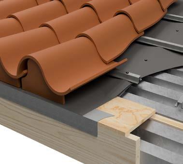
TILE FASTENED TO BATTENS WITH SELF-TAPPING CREWS OR WIRED IN PLACE, HEAD OF FASTENERS SHALL BE LARGER THAN NAIL HOLE IN TILE
CODE APPROVED REINFORCED DRAPED UNDERLAYMENT ATTACHED TO COUNTER BATTENS WITH MECHANICALLY DRIVEN CAPPED FASTENERS
BATTENS FASTENED TO METAL DECK WITH SCREWS OR OTHER CODE APPROVED FASTENERS
METAL DECK
EAVE RISER OR BIRD STOP
SUPPORT SHIM (WHERE REQUIRED)
PERIMETER DRIP EDGE FLASHING
FOR FIRE-RATED SYSTEMS, ADDITIONAL COMPONENTS MAY BE REQUIRED
The pre-engineered roof systems are included for informational purposes only and are not recognized under evaluation reports for roof tiles
NOTES:
1. Vertical battens to be metal or as approved or designed as per metal deck manufacturer.
2. For recommended underlayment and fastening, see Page 13, Table 1A, 1B & 1C.
3. An eave drip flashing is required with stucco fascia, EIFS (Exterior Insulated Finish System) and flush fascia perimeter edges.
4. Eave closures should be the height equal to combined thickness of batten system and thickness of one course of tile.
5. On Type I (Non-Combustible) building, all components must be fire-resistant as approved by local building official.
6. Dimensions shown are minimums and are intended to be approximate to all for reasonable tolerances due to field conditions.
Installation on Metal Deck—Considerations
Adhesive Based Systems—Solid Sheathing
FOR INFORMATIONAL PURPOSES ONLY—THESE HAVE NOT BEEN EVALUATED BY UNIFORM ES.
SELF-ADHERING UNDERLAYMENT COMPATIBLE WITH SUBSTRATE
TILES FASTENED ACCORDING TO ADHESIVE MANUFACTURERS CODE APPROVED INSTRUCTIONS
RIGID SHEATHING TO SUPPORT UNDERLAYMENT MAY BE PLYWOOD OR NON-COMBUSTIBLE SUBSTRATE AS APPROVED BY LOCAL BUILDING OFFICIAL
EAVE RISER OR BIRD STOP
PERIMETER DRIP EDGE FLASHING
METAL DECK
FOR FIRE-RATED SYSTEMS, ADDITIONAL COMPONENTS MAY BE REQUIRED
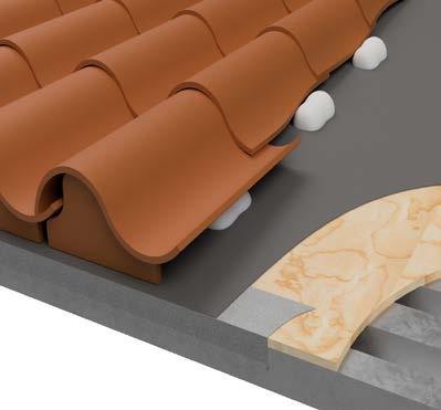
NOTE: ADHESION OF UNDERLAYMENT TO SUBSTRATE SHALL BE IN ACCORDANCE WITH ASSEMBLIES RECOGNIZED IN A CURRENT ICC-ES EVALUATION REPORT FOR ROOF TILE ADHESIVES EVALUATED TO THE REQUIREMENTS OF AC-152
The pre-engineered roof systems are included for informational purposes only and are not recognized under evaluation reports for roof tiles
NOTES:
1. On Type I (Non-Combustible) building, all components must be fire-resistant as approved by local building official.
2. Dimensions shown are minimums and are intended to be approximate to all for reasonable tolerances due to field conditions.
Installation on Metal Deck—Considerations
Adhesive Based Systems—On Counter Batten
FOR INFORMATIONAL PURPOSES ONLY—THESE HAVE NOT BEEN EVALUATED BY UNIFORM ES.
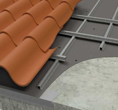
UNDERLAYMENT OR CODE APPROVED SEALED SYSTEM
TILE FASTENED TO BATTENS WITH SELF-TAPPING SCREWS OR WIRED IN PLACE, HEAD OF FASTENER SHALL BE LARGER THAN NAIL HOLE IN TILE
BATTENS FASTENED TO METAL DECK WITH SCREWS OR OTHER CODE APPROVED FASTENERS
VERTICAL COUNTER BATTENS FASTENED TO CONCRETE DECK WITH SCREWS, EXPANDING LEAD PINS, OR OTHER APPROVED FASTENERS AS DESIGNED
CONCRETE DECK OR APPROVED STRUCTURAL SUBSTRATE
EAVE RISER OR BIRD STOP
PERIMETER EDGE DRIP FLASHING
FOR FIRE-RATED SYSTEMS, ADDITIONAL COMPONENTS MAY BE REQUIRED OPTION:
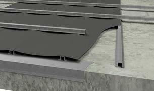
NOTES:
1. Vertical battens to be of metal or as approved or designed as per metal deck manufacturer.
The pre-engineered roof systems are included for informational purposes only and are not recognized under evaluation reports for roof tiles
2. Dimensions shown are minimums and are intended to be approximate to all for reasonable tolerances due to field conditions.
Installation On Metal Deck—Considerations Adhesive Based Systems—Direct To Deck
FOR INFORMATIONAL PURPOSES ONLY—THESE HAVE NOT BEEN EVALUATED BY UNIFORM ES.
SELF-ADHERING UNDERLAYMENT OR CODE APPROVED SEALED SYSTEM COMPATIBLE WITH ROOF TILE ADHESIVE
TILES FASTENED ACCORDING TO ADHESIVE MANUFACTURERS CODE APPROVED INSTRUCTIONS
PRIMER WHERE REQUIRED FOR SELF-ADHERED UNDERLAYMENT APPLICATIONS, REFER TO UNDERLAYMENT MANUFACTURER CODE APPROVED INSTALLATION INSTRUCTIONS
EAVE RISER OR BIRD STOP TO ENSURE PROPER HEIGHT
PERIMETER DRIP EDGE FLASHING
CONCRETE DECK OR APPROVED STRUCTURAL SUBSTRATE FOR FIRE-RATED SYSTEMS, ADDITIONAL COMPONENTS MAY BE REQUIRED
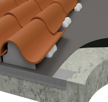
NOTE: ADHESION OF UNDERLAYMENT TO SUBSTRATE SHALL BE IN ACCORDANCE WITH ASSEMBLIES RECOGNIZED IN A CURRENT ICC-ES EVALUATION REPORT FOR ROOF TILE ADHESIVES EVALUATED TO THE REQUIREMENTS OF AC-152
The pre-engineered roof systems are included for informational purposes only and are not recognized under evaluation reports for roof tiles
NOTES:
1. Dimensions shown are minimums and are intended to be approximate to all for reasonable tolerances due to field conditions.
Wire Tie Systems On S-Tile
FOR INFORMATIONAL PURPOSES ONLY—THESE HAVE NOT BEEN EVALUATED BY UNIFORM ES.
AT TOP & BOTTOM ANCHOR WRAP TWISTED WIRE BACK ON ITSELF MIN . 3 TIME FULL TURNS .
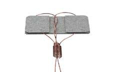

OPTIONAL: NOSE CLIPS ON STEEP SLOPES OR HIGH WIND ZONE REQUIREMENTS SPECIFY DIMENSION PER MANUFACTURER SPECIFICATIONS FOR ALL WIRE
IN-LINE ANCHORS TO BE SPACED AND FASTENED AS REQUIRED ANCHORS TO BE AS SHOWN .
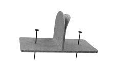
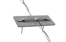
2 ANCHOR WIRE
CODE APPROVED FASTENING SYSTEM
DECK ANCHORS INSTALLED PER ANCHOR MANUFACTURERS ICC-ES EVALUATION REPORT
TILE WIRE TO BE WRAPPED AROUND ITSELF 3 FULL REVOLUTIONS AT EACH JUNCTION- TYPICAL FOR ALL TILES
The pre-engineered roof systems are included for informational purposes only and are not recognized under evaluation reports for roof tiles
Wire Tile Systems On Clay S-Tile
AT TOP & BOTTOM ANCHOR WRAP TWISTED WIRE BACK ON ITSELF MIN 3 TIME FULL TURNS

OPTIONAL: NOSE CLIPS ON STEEP SLOPES OR HIGH WIND ZONE AS REQUIRED COVER TILES TO BE ATTACHED OR OTHERWISE SECURED UNDERLAYMENT NOT SHOWN FOR CLARITY
IN-LINE ANCHORS TO BE SPACED AND FASTENED AS REQUIRED ANCHORS TO BE AS SHOWN
2 ANCHOR WIRE
CODE APPROVED FASTENING SYSTEM
DECK ANCHORS INSTALLED PER ANCHOR MANUFACTURERS
ICC-ES EVALUATION REPORT
TILE WIRE TO BE WRAPPED AROUND ITSELF 3 FULL REVOLUTIONS AT EACH JUNCTION- TYPICAL FOR ALL TILES
The pre-engineered roof systems are included for informational purposes only and are not recognized under evaluation reports for roof tiles
Nailer Installations—(Optional) Cap & Pan
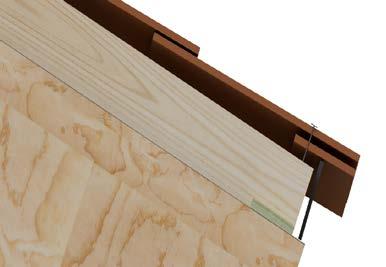
END VIEW OF ABOVE 2 X NAILER TO SUPPORT THE COVER TILE/CAP TILE
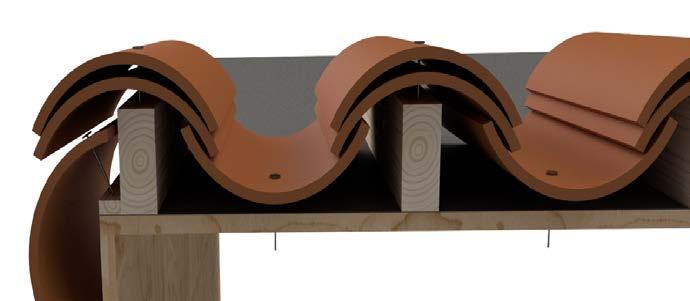
TURN UNDERLAYMENT DOWN 1"
Turret & Cone Shaped Installations
WE OFTEN SEE A CONE ROOF OR CONICAL ROOF SHAPE IN OLD BUILDINGS AND TRADITIONAL DESIGN BUILDINGS. HOW DID THEY DESIGN AND BUILD THIS SHAPE OF ROOF?
TRI listed a few concepts of “Cone Roof” or “Conical Roof from our field experiences. TRI uses the “Cone Roof” name for explanation purposes
Key Design Concepts —Architects or builders must consider the following key lists when designing cone roofs
1 The base of the cone roof must be a true circle The radius of the base cone roof has to be the same distance, and it has to be a true circle You cannot make any oval base shape . If the base design is not a true circle, the roof slope distance changes and tiles cannot be installed on the same horizontal line You can design different pie or angles of the cone roof For example, you can make a 360-degree, 180-degree, 45-degree, or any angle as long as the tile can be installed at that angle
2. The cone roof tile exposure and the field tiles exposure should be the same.
Keep the cone roof tiles’ exposure and the field tiles’ exposure the same, except near the tops’ last few courses. Near the tops’ courses, it may need an adjustment on the cone roof tiles’ exposure depending on the size of the cone roof Keeping the same exposure is essential to a distance appearance of point of view. When you use One Piece S tile for field tile sections, you can use Two Piece Mission Tile for the cone roof section as long as Two-Pieces and One-Piece S tiles are the same width and vertical exposure, and have a close size of the crown shape at the eave line You do not have to use the entire roof with the Two-Piece mission tile
3. It requires a metal cap or finial to cover the top of the cone roof. The roof tile cannot be a line, and it must have a minimum of 2" (5 cm) base triangles. Cone tile can reach close to the top of the roof; however, it needs to be covered with a metal cap or finial at least 12" (31 cm) distance from the top. The metal cap or finial must use the same roof pitch and add thinness of tile from the roof deck to fit and co the top.
4 . A sealed underlayment roof is required . The cone roof tile is decorative . Depending on the size of the cone roof, you can use regular field tile at the beginning of a few courses; however, after a few courses, you need to modify tiles to fit the cone roof shape. The cone roof requires a sealed underlayment to protect against any water leaks
Also, the cone roof must be covered with a cap sheet to protect it from UV . The cone roof tile is strictly a decorative roof .
5 How to order Pre-cut cone roof tiles . Some tile manufacturers offer pre-cut cone shape roof tiles . To order the pre-cut cone roof tiles, the roofing contractor must send the following information to the manufacturer.
a. Architectural scaler roof drawing with elevation drawing and the field tile color Or
b Provide roof pitch, angle of the pie shape, diameter or radius of the base cone roof, the number of cone roofs, and the field tile color
The roof tile manufacturer will provide a worksheet before you order the tiles and you should be able to double-check this worksheet . You can proceed with the ordering process of the cone roof tiles through your vendor
To bid on the job or install the cone roof tiles, the roofing contractor must be aware that each cone roof tile shape changes at each course depending on the size of the cone roof Some manufacturers offer pre-cut cone roof tiles You can contact the manufacturer whom you will use the field tiles from.
Turret & Cone Shaped Installations
1. Flat tile cone roof —If the contractor does not use pre-cut cone roof tiles, the contractor must cut trapezoid shapes from field tiles to fit the cone roof at the job site. Avoid any open gaps between tiles. Please be aware that cutting trapezoid shapes is not easy and also dangerous You can re-start using a large size of trapezoid shape tiles near the top when tiles become too small to use You must re-adjust the trapezoid angle to fit the cone roof. Installation of a flat cone roof is the same as shingle flat tiles. There is no side water channel .
2. Two Piece Mission Cone Roof Tile —A two-piece mission cone roof differs from a flat tile cone roof. Two-piece mission tiles width exposure can be adjusted up to a certain point All two-piece cone shape roof top and pan tiles are the same as the top tiles Install narrowed shape side toward the top of the roof. Standard two-piece field pan tiles have a nail hole at the wide side of the tile. But the top and pan tiles of the cone roof tile have a nail hole on the narrow side of the tiles When cone tiles become less than 5" (12 9 cm) wide, the tile loses the crown shape and becomes a flat bar tile. Restart the field tile again on the next upper course; it loses the appearance of a cone roof and becomes a high punch list Contact the Two-Piece Mission Tile manufacturer to get a smaller shape of the two-piece mission. Near the top roof, there is no space to install pan tiles. Install top tiles only to finish up the top section. If there is any gap between the tiles, fill the gap with mortar cement to protect the underlayment against UV.
3 . The architectural drawing vs . the actual framework should have the same slope distance before installing the underlayment . Pre-cut cone roof tiles are all custom-made to fit the specified cone roof. The factory produces cone roof tiles with the provided architectural drawings. When the cone roof frame is complete, the roofing contractor must check the cone roof slope distance and the angle of the pie shape. If they find a different dimension, it is essential that the roofing contractor must request to fix the roof deck before installing the underlayment or notify the manufacturer to adjust the cone roof tiles . Otherwise, the cone roof tiles will not fit the specified cone roof.
4. Recommendation —Cutting many cone roof tiles at the job site is very dangerous to the worker In any case, the contractor needs to cut the cone roof tiles; it is recommended to use a wet saw to cut tile on ground level to avoid tile-cutting dust all over the roof tile .
Usually, manufacturers produce pre-cut cone roof tiles during the raw material processes, and they do not cut tile from the finished field tiles. The benefit of using pre-cut cone roof tiles is that they will match the tile’s exposure and color scheme with the field tile. Also, it will save many hours of labor and materials .
Please get in touch with TRI or the tile manufacturers for more detail .
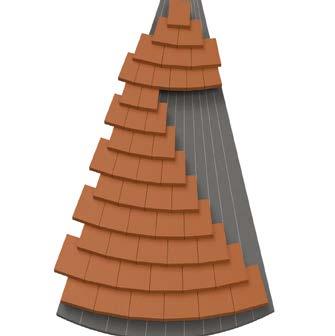
Staggered
Installation
STAGGERED INSTALLATION: Unlike standard installations, where battens are set to keep uniform coursing, a staggered installation requires battens to be set 1" closer together for each of the staggered courses for each inch of stagger
1 Depending upon the pitch and of the roof and the nailing requirements, one tile is hung on the batten and the next tiles may be pulled up at random and nailed to the roof deck .
2 . For each inch of stagger, you may need 10% more tiles and corresponding rake .
3 The sequence of the stagger should be determined prior to installation Once established the tiles may be installed making sure all tiles have at minimum of a 3" headlap
4 . Where the tile channel (underlock) extends and exposed, it may be clipped to provide a more aesthetic looking roof .

As an alternative to mechanical fastening of roof tiles, the use of foam adhesive securement systems that are approved by the authority having jurisdiction may be used .
The restrictions, if any, are found in the code approval or evaluation report and will address any special considerations for underlayment attachment climate restrictions and the required amount and placement of the foam adhesive materials to provide the code required uplift resistance when installed on direct deck and batten applications for concrete and clay tile .
When deciding to use foam adhesives for the securement of tile, consideration must be made on the compatibility of the adhesive to the underlayment surface Although most code approved foam adhesives bond well to a variety of products like smooth or granulated underlayments, metal, concrete, clay, wood, etc ., typically, they do not adhere to polyethylene or silicon surfaced products .
Consult with the manufacturer of the solar system and mounting attachments for additional requirements and limitations. The roof must be constructed to support the loads of the roof-installed solar system Roof-mounted or integrated systems that serve as roof coverings must conform to the requirements of Chapter 9 of the IRC, Chapter 15 of the IBC and/or other building, electrical, plumbing or other applicable codes. In addition, check with your local building official for specific licensing requirements. Install solar systems incorporated into roof tile systems in accordance with the requirements of this Installation manual, solar systems manufacturer’s installation guidelines and applicable building code requirements
Appropriate flashing that properly directs and keeps water flow on the surface of the tile or redirects the flow via appropriate flashing onto the surface of the tile or off the roof is critical. Deck-mounted or other systems that penetrate the tile or roof deck shall have both primary roof tile flashing and secondary deck flashing .
Design wind speed calculation must be furnished from the solar manufacturer that meet or exceed local requirements, fire rating of the system verified if required and UL & CEC listing as required.
The following pages provide the information for installing concrete and clay roof tiles based upon the current ASCE-7-16 code requirements For installations that were under previous versions, such as ASCE-7-10 or ASCE-7-05, please refer to our previous editions of the TRI Alliance installation manuals that can be downloaded from our website: tileroofing.org
Please refer to the manufacturer's valid code approval for additional wind design details
The installation requirements in the Table 5 series provide the normal installation guidelines for concrete and clay tile to comply with the Florida Building Code and International Building Code. The installation of tile in the specific regions of the country that are identified by FBC/IBC as subjected to wind speeds in excess of 110 miles per hour (Vasd), may be required to have additional fastening options not found in Table 3 .
The Tile Roofing Industry Alliance (TRI) has derived various uplift resistance values for nail, screws and adhesive fastening systems on Plywood Sheathing Some of these methods of installation may have limiting factors depending upon wind speed, roof slope and roof height Please consult with your tile, underlayment and adhesive manufacturers or design professional for additional information about these optional systems for those unique installations .
The following design aids are provided to the roof designer for consideration in determining the required aerodynamic uplift moment for roof tiles for wind applications beyond the prescriptive requirements in the ICC/IRC
These tables were developed based on the requirements of ASCE 7-16 for a tile factor of 1 407 ft3 The Tile Factor is determined from the following equation:
TF = b*L*La(ft3) where:
b = exposed width (ft)
L = roof tile length (ft)
L a = 0 76*L
Or use the tile factor ratio that provides the ratio of the actual tile to the 1 407 (ft3) that some manufacturers have in their formal Product Approvals .
Conversion from Nominal Design Wind Speed to Vasd to Ultimate Design Wind Speed Vult shall be converted as Vasd = Vult * 0 6 or from the following table;
For SI: 1 mile per hour = 0 44 m/s A linear interpolation is permitted
(EXAMPLES FOR ILLUSTRATIVE PURPOSES ONLY)
EXAMPLE 1
A building is a low-rise structure in an Exposure C region where the ultimate design wind speed is 190 mph The building is a Category II structure . The mean height of the building is 40 feet . The roof is a gable roof with a roof slope of 7:12 . The terrain around the building does not abruptly change so as to create any wind speedup effects due to channeling or shielding The building is not located on a hill, ridge or escarpment that would cause the wind to speedup. The roof tiles will be flat/low profile concrete roof tiles with a total tile length of 17" and exposed width of 11 07" The roof tiles weigh 9 pounds each The roof covering is installed direct to deck on solid sheathing
Calculate the Required Aerodynamic Uplift Moment and use the Allowable Aerodynamic Uplift Resistance Risk Category from (ASCE 7-16 Chapter 26 .10-1):
Velocity pressure:
qh = 0 .00256*K z *K zt *Kd * Ke*V 2 qh = velocity pressure at height z (psf) V = Wind speed (Vult) in MPH
Note: The ultimate design wind speeds, Vult, have been converted to nominal design wind speeds, Vasd, since roof tile attachments systems are based on test results.
Ke = ground elevation pressure (ASCE 7-16 Chapter 26.10-1)
Ke = 1.0 up to 1,000 ft.
Kz = velocity pressure exposure coefficient at height z (ASCE 7-16 Chapter 26.10-1) Kz = 1.04
Kzt = topographic factor: Kzt = 1.0 (ASCE 7-16 Chapter 26.8.2)
Kd = wind directionality factor: (Kd = 0.85) (ASCE 7-16 Chapter 26.6-1)
Vult = basic wind speed (mph) Fig. 26.10-1 (190 mph) qh=.00256* Kz* Kzt* Kd* Ke * V2 = .00256 (1.04) (1.0) (0.85) (1.0) (147mph2) = 48.9 psf
From table left qh = 49.00 psf
; ALLOWABLE
GCp For Roof Zones Gable 27 to 45
From Table for 27 to 45°
EXAMPLE 2
The building in Example 2 is the same design requirements as found in Example 1 except the tile factor is now being calculated for a different tile dimension . For this example, a tile with an exposed width of 12" and a total tile length of 17" is being designed for installation
In Example 1 we determined:
Ma = qh CL b L La (1 0-GC) = 49 0 psf (0 2) (0 92') (1 42') (1 08') (1 - [-2 00]) = 41 4 ft-lbf
For this new tile dimension we will calculate the new Ma:
From Table for to
CL = Lift Coefficient qh = 49 psf
b = Exposed width (ft)
CL = 0 2
L = Roof tile length b = 0 92
La = Moment arm from axis of rotation to the point of uplift on the roof tile (ft)
L= 1 .42 ft Ma = qh CL b L La (1 0-GC) = 49 0 psf (0 2) (1 0') (1 42') (1 08') (1 - [-2 00]) = 45 23 ft-lbf
From Table 5 MF, a proper fastening option will be selected that will meet the 45.2 ft-lbf
Figure 1 0 Hip Roof Zone Designation
= HIGH PRESSURE ZONES = 3
OTHER = LOW PRESSURE ZONES = 1,2E,2R
a = 10% OF LEAST HORIZONTAL DIMENSION OR 0 4H, WHICHEVER IS SMALLER, BUT NOT LESS THAN EITHER 4% OF LEAST HORIZONTAL DIMENSION OR 3 FT (0 9 M)
B = HORIZONTAL DIMENSION OF THE BUILDING IN FEET
h = MEAN ROOF EHIGHT (MRH) IN FEET (EAVE HEIGHT PLUS RIDGE HEIGHT DIVIDED BY 2)
0- = ANGLE OF ROOF PLANE FROM HORIZONTAL IN DEGREES (SLOPE OR PITCH)
Figure 2 0 Gable Roof Zone Designation
= HIGH PRESSURE ZONES = 3E & 3R
OTHER = LOW PRESSURE ZONES = 1, 2E, 2R & 2N
Hip Roof – ASCE 7-16 - Wind speed (Vult) in MPH
Exposure B – Tile Factor = 1.407 ft3
Notes:
LPZ - Low Pressure Zones 1, 2e,& 2r for Hip Roofs, HPZ - High Pressure Zones 3 for Hip Roofs h/B ≤ 0.80 values used where applicable (most conservative Wind speed Vult. Refer to tile manufacturer for additional information. See Figure 1 on pg. 84 for additional details on on roof zone designations
Drawing shown depicts the application of all tile profiles. Unless otherwise noted, it would apply to either concrete or clay tiles.
Hip Roof – ASCE 7-16 - Wind Speed (Vult) in MPH
Exposure C – Tile Factor = 1.407 ft3
Notes: See Table 5HB
TABLE 5 HD
Hip Roof – ASCE 7-16 - Wind Speed (Vult) in MPH
Exposure D – Tile Factor = 1.407 ft3
Notes: See Table 5HB
Gable Roof – ASCE 7-16
Exposure B – Tile Factor = 1.407 ft3 Wind Speed = Vult
Notes: LPZ - Low Pressure Zones 1, 2e,& 2r for Gable Roofs HPZ = High Pressure Zones 3e & 3r for Gable Roofs Wind speed Vult. Refer to tile manufacturer for additional information. See Figure 1 and 2 on pg. 84 for additional details on on roof zone designations
Drawing shown depicts the application of all tile profiles. Unless otherwise noted, it would apply to either concrete or
Gable Roof – ASCE 7-16
Exposure C – Tile Factor = 1.407 ft3 Wind Speed = Vult
Notes: See Table 5GB
Gable Roof – ASCE 7-16
Exposure D – Tile Factor = 1.407 ft3 Wind Speed = Vult
Notes: See Table 5GB
Mechanical Roof Tile Resistance Values (ft-lbf) For Tile
1- 10d smooth or screw shank snail, with clip 2- 10d, smooth or screw shank nail, with clip 2-10d ring shanked nail 2- 10d ring shank nail, with headlap
1- 10d smooth or screw shank snail, with clip 2- 10d, smooth or screw shank nail, with clip 2- 10d ring shanked nail
For mean roof heights over 60 ft, engineering calculations must be submitted for permitting.
Notes for Table 5 MF:
1 For attachment systems not listed in the table for 19/32" sheathing use the allowable aerodynamic uplift resistance from the table for 15/32" sheathing .
2 Fasteners shall have a minimum edge distance of 1½ inches from the head of the tile and located in the pan of the tile to obtain the values in Table 5 MF . Consult the tile manufacturer for additional limitations or restrictions .
3 . Ring shank nails shall be 10d ring shank corrosion resistant steel nails with the following minimum dimensions: (3 inches long, 0.283 inch flat head diameter, 0.120 inch undeformed shank diameter or 0.131 inch screw diameter).
4 . Smooth or screw shank nails shall be 10d corrosion resistant steel (with the following minimum dimension 3 inch long, 0 . 283 inch flat head diameter, 0.120 inch undeformed shank diameter or 0.131 inch screw diameter).
5 Screws are #8 course threaded, 2 5 inches long corrosion-resistant steel wood screws conforming to ANSI/ASME B 18 6 1
6 The fastener hole nearest the overlock shall be used when a single nail or screw is required The fastener hole nearest the underlock and the fastener hole nearest the overlock shall be used when two nails or screws are required
7. When using eave and field clips, attachment of the tiles is accomplished by a combination of nails and clips. Tiles are nailed to the sheathing or through the battens to the sheathing with one or two 10d corrosion resistant nails (Note 2 and 3 above) as required by Tables 5 and 6 Additionally, each tile is secured with a 0 060 inch thick and 0 5 inch wide clip which is secured to the plywood sheathing or eave fascia, as appropriate, with a single nail per clip The nail shall be placed in the hole closest to the tile for clips having more than one nail hole The following clip/nail combinations are permitted:
(1) Aluminum alloy clip with 1.25 inch HD galvanized roofing nail (0.128 inch shank diameter).
(2) Galvanized steel deck clip with 1.25 inch HD galvanized roofing nail (0.128 inch shank diameter).
(3) Stainless steel clip with 1.25 inch HD galvanized roofing nail (0.128 inch shank diameter).
8 Field clips and eave clips are to be located along the tile where the clip's preformed height and the tile's height above the underlayment are identical
9 . Counter batten values not included .
10 For attachment systems not listed in table for 15/32" sheathing, use allowable aerodynamic uplift moment from table for 15/32" sheathing
11 . The allowable aerodynamic uplift moments include a generic restoring gravity moment of 6 .5 ft-lbf for a direct deck installation and a generic restoring gravity moment of 5 5 ft-lbf for a batten installation
Please refer to the manufacturer's valid code approval for additional wind design details.
The installation requirements in the Table 6 series provide the normal installation guidelines for concrete and clay tile to comply with the Florida Building Code and International Building Code. The installation of tile in the specific regions of the country that are identified by IBC as subjected to wind speeds in excess of 110 miles per hour (Vasd), may be required to have additional fastening options not found in Table 6 .
The Tile Roofing Industry Alliance (TRI) has derived various uplift resistance values for nail, screws and adhesive fastening systems on Plywood Sheathing Some of these methods of installation may have limiting factors depending upon wind speed, roof slope and roof height Please consult with your tile, underlayment and adhesive manufacturers or design professional for additional information about these optional systems for those unique installations .
The following design aids are provided to the roof designer for consideration in determining the required aerodynamic uplift moment for roof tiles for wind applications beyond the prescriptive requirements in the FBC/IBC
These tables were developed based on the requirements of ASCE 7-22 for a tile factor of 1 407 ft3 The Tile Factor is determined from the following equation:
TF = b*L*La(ft3) where:
b = exposed width (ft)
L = roof tile length (ft)
La = 0 76*L
Or use the tile factor ratio that provides the ratio of the actual tile to the 1.407 (ft3) that some manufacturers have in their formal Product Approvals.
Conversion to Nominal Design Wind Speed Vasd from Ultimate Design Wind Speed Vult shall be converted as Vasd = Vult * √0.6 or from the following table; tables were calculated using Vasd
For SI: 1 mile per hour = 0 44 m/s A linear interpolation is permitted
A building is a low-rise structure in an Exposure C region where the ultimate design wind speed is 170 mph The building is a Category II structure . The mean height of the building is 40 feet . The roof is a gable roof with a roof slope of 7:12 . The terrain around the building does not abruptly change so as to create any wind speedup effects due to channeling or shielding The building is not located on a hill, ridge or escarpment that would cause the wind to speedup. The roof tiles will be flat/low profile concrete roof tiles with a total tile length of 17" and exposed width of 11 .07" . The roof tiles weigh 9 pounds each . The roof covering is installed direct to deck on solid sheathing
Calculate the Required Aerodynamic Uplift Moment and use the Allowable Aerodynamic Uplift Resistance
Risk Category from (ASCE 7-22 -Table 1 5-1D): Velocity pressure: qh = 0 00256*Kh*Kzt* Ke*V2 qh = velocity pressure at height z (psf)
Note: The ultimate design wind speeds, Vult , have been converted to nominal design wind speeds, Vasd , since roof tile attachments systems are based on test results
Ke = ground elevation pressure = (ASCE 7-22 Chapter 26 9)
Ke = 1 0 up to 1,000 ft
Kzt = topographic factor: Kzt = 1 0 (ASCE 7-22 Chapter 26 .8 .2)
Kh = Velocity Pressure Coefficient (ASCE-7-22 10-2)
V = basic wind speed (mph) Fig 26 5-1D (170 mph)
qh = 00256* kh*Kzt*Ke*V2 = 00256 (1 04) (1 0) (1 0) (132mph2) = 46 .38 psf
From table left qh = 46.9 psf
REQUIRED AERODYNAMIC MOMENT, Ma; ALLOWABLE
Sample Calculations Aerodynamic Moment, Ma:
Maximum Required Aerodynamic Uplift Moment, Ma (ft-lbf)
GCp for Roof Zones
Gable 27° to 45° Wind Area = 10 ft 2 Zone 1 -1 8
= Exposed width (ft)
Roof Tile Length (ft)
La - Moment arm from the axis of rotation to the point of uplift on the roof tile (ft)
OF ATTACHMENT SYSTEM (EXAMPLE FOR ILLUSTRATIVE PURPOSES ONLY)
The building in Example 2 is the same design requirements as found in Example 1 except the tile factor is now being calculated for a different tile dimension . For this example, a tile with an exposed width of 12" and a total tile length of 17" is being designed for installation
In Example 1 we determined:
Ma = qh CL b L La (1.0-GC) = 46.9 psf (0.2) (0.92') (1.42') (1.08') (1 - [-2.5]) = 42.89 ft-lbf
For this new tile dimension we will calculate the new Ma
CL = Lift coefficient
b = Exposed width (ft)
La = Roof tile length (ft)
La = Moment arm from the axis of rotation to the point of uplift on the roof tile (ft)
CL = 0 . 2
b = 1 0 ft
L = 1 42ft
La = 1 08 L (ft)
Ma = qh CL b L La (1.0-GC) = 46.9 psf (0.2) (1.0') (1.42') (1.08') (1 - [-2.5]) = 50.34 ft-lbf
From Table 6MF, a proper fastening option will be selected that will meet the 50.34 ft-lbf
FIGURE 3.0 HIP ROOF ZONE DESIGNATION
FIGURE 4.0 GABLE ROOF ZONE DESIGNATION
= PERIMETER ZONE 3
= PERIMETER ZONE 3
Notation:
a = 10% if least horizontal dimension or 0.4h, whichever is smaller, but not less than either 4% of least horizontal dimension or 3ft (0.9m). If an overhang exists, the edge shall be measured from the outside edge of the overhang. The horizontal dimensions used to compute the edge distance shall not include any overhang dimensions.
B = Horizontal dimension of building measured normal to wind direction, ft (m).
h = Mean roof height, in ft (m), except that eave height shall be used for 0- ≤ 10 deg.
0- = Angle of plane of roof from horizontal, degrees.
Drawing shown depicts the application of all tile profiles. Unless otherwise noted, it would apply to either concrete or clay tiles.
Hip Roof – ASCE 7-22- Wind speed (Vult) in MPH Exposure B – Tile Factor = 1.407 ft3
LPZ – Low Pressure Zone 2 for Hip Roofs . HPZ – High Pressure Zone 3 for Hip Roofs Wind speeds are Vult Refer to the tile manufacturer for additional information See Figures 3 0 & 4 0 on page 96 for additional details on roof zone designations
Hip Roof – ASCE 7-22 - Wind Speed (Vult) in MPH
Exposure C – Tile Factor = 1.407 ft3
LPZ – Low Pressure Zone 2 for Hip Roofs HPZ – High Pressure Zone 3 for Hip Roofs Wind speeds are Vult Refer to the tile manufacturer for additional information See Figures 3 0 & 4 0 on page 96 for additional details on roof zone designations
Drawing shown depicts the application of
6 HD
Hip Roof – ASCE 7-22 - Wind Speed (Vult) in MPH
Exposure D – Tile Factor = 1.407 ft3
& 4 0 on page 96 for additional details on roof zone designations
Gable Roof – ASCE 7-22 - Wind Speed (Vult) in MPH
Exposure B – Tile Factor = 1.407 ft3
a = 10% of least horizontal dimension or 0 4h, whichever is smaller, but not less than either 4% of least horizontal dimension or
LPZ = Low Pressure Zone = 2 for Gable Roofs; HPZ = High Pressure Zone = 3 for Gable Roofs Refer to tile manufacturers for additional information on tile installation requirements
Gable Roof – ASCE 7-22 - Wind Speed (Vult) in MPH
Exposure C – Tile Factor = 1.407 ft3
LPZ = Low Pressure Zone = 2 for Gable Roofs; HPZ = High Pressure Zone = 3 for Gable Roofs Refer to tile manufacturers for additional information on tile installation requirements
Roof – ASCE 7-22 - Wind Speed (Vult) in MPH
Exposure D – Tile Factor = 1.407 ft3
a = 10% of least horizontal dimension or 0 4h, whichever is smaller, but not less than either 4% of least horizontal dimension or
LPZ = Low Pressure Zone = 2 for Gable Roofs; HPZ = High Pressure Zone = 3 for Gable Roofs Refer to tile manufacturers for additional information on tile installation requirements
Mechanical Roof Tile Resistance Values (ft-lbf) For Tile
Batten
1- 10d smooth or screw shank snail, with clip 2- 10d, smooth or screw shank nail, with clip 2-10d ring shanked nail 2- 10d ring shank nail, with headlap
1- 10d smooth or screw shank snail, with clip 2- 10d, smooth or screw shank nail, with clip 2- 10d ring shanked nail
19/32" Direct Deck 2- 10d ring shanked nail
For mean roof heights over 60 ft, engineering calculations must be submitted for permitting.
Notes for Table 6MF:
1. For attachment systems not listed in the table for 19/32" sheathing use the allowable aerodynamic uplift resistance from the table for 15/32" sheathing.
2. Fasteners shall have a minimum edge distance of 1½ inches from the head of the tile and located in the pan of the tile to obtain the values in Table 6 MF. Consult the tile manufacturer for additional limitations or restrictions.
3. Ring shank nails shall be 10d ring shank corrosion resistant steel nails with the following minimum dimensions: (3 inches long, 0.283 inch flat head diameter, 0.120 inch undeformed shank diameter or 0.131 inch screw diameter).
4. Smooth or screw shank nails shall be 10d corrosion resistant steel (with the following minimum dimension. 3 inch long, 0.283 inch flat head diameter, 0.120 inch undeformed shank diameter or 0.131 inch screw diameter).
5. Screws are #8 course threaded, 2.5 inches long corrosion-resistant steel wood screws conforming to ANSI/ASME B 18.6.1.
6. The fastener hole nearest the overlock shall be used when a single nail or screw is required. The fastener hole nearest the underlock and the fastener hole nearest the overlock shall be used when two nails or screws are required.
7. When using eave and field clips, attachment of the tiles is accomplished by a combination of nails and clips. Tiles are nailed to the sheathing or through the battens to the sheathing with one or two 10d corrosion resistant nails (Note 2 and 3 above) as required by Tables 5 and 6. Additionally, each tile is secured with a 0.060 inch thick and 0.5 inch wide clip which is secured to the plywood sheathing or eave fascia, as appropriate, with a single nail per clip. The nail shall be placed in the hole closest to the tile for clips having more than one nail hole. The following clip/nail combinations are permitted:
(1) Aluminum alloy clip with 1.25 inch HD galvanized roofing nail (0.128 inch shank diameter).
(2) Galvanized steel deck clip with 1.25 inch HD galvanized roofing nail (0.128 inch shank diameter).
(3) Stainless steel clip with 1.25 inch HD galvanized roofing nail (0.128 inch shank diameter).
8. Field clips and eave clips are to be located along the tile where the clip's preformed height and the tile's height above the underlayment are identical.
9. Counter batten values not included.
10. For attachment systems not listed in table for 15/32" sheathing, use allowable aerodynamic uplift moment from table for 15/32" sheathing.
11. The allowable aerodynamic uplift moments include a generic restoring gravity moment of 6.5 ft-lbf for a direct deck installation and a
moment of 5.5 ft-lbf for a batten installation
Abutment: The intersection between the roof and the chimney, wall or other vertical face .
Adhesives : A bonding agent to join two surfaces for the purpose of permanent attachment as approved by the local building official.
Anti-Ponding: A device such as beveled cant strip or shop formed sheet metal is recommended at all raised fascia conditions to support the underlayment
Batten: A nonstructural horizontal fastening strip to which the roof tiles are attached
Batten Lugs: Protrusions (anchor lugs) on the underside of the tile designed to engage over the upper edge of tiling battens
Bedding: Refers to the installation of roof tiles to a mortar or adhesive foam patty and is structural in nature for the basic securement
Bird Stop: A product used at the eave of a profile tile roof to stop birds from entering below the tile .
Booster Tile: Normally 3"-4" long tile strip used to lift up the cover tile. Sometimes it is used in boosting up field tile to create an authentic looking roof .
Cant Angle: The angle formed between the upper surface of the installed roof tile and the roof deck
Clay Rooftile: An interlocking or non-interlocking clay roof covering, used to cover the roof surface .
Concrete Rooftile: An interlocking, or non-interlocking concrete roof covering, used to cover the roof surface
Counter Battens: Vertical furring strips running beneath and perpendicular to horizontal tile batten, to allow drainage and air flow beneath the roof tile. Also known as strapping.
Counter Flashing: A flashing material that provides the enclosure at the transition line between the roof to wall flashing at intersecting vertical surfaces.
Counter Batten System: A method of elevating horizontal battens above the roof deck to allow drainage and air flow beneath the horizontal battens and roof tile
Cricket: See Saddle.
Dead Loads: The weight of all materials of construction incorporated into the roof assembly including but not limited to, fixed service equipment, roof tiles, battens, underlayment, flashing, roof deck, etc.
Direct Deck: Those tiles fastened directly to the roof deck without the use of battens
Eave: Outer edge of the roof downslope
Eave Closure: A material available for S-tile or Pan and Cover tile . Eave closures are used to close the convex opening created by the shape of the tile at the eave This accessory also provides the proper rise for the first course of tile. See Bird Stop .
Eave Riser: Method/material used for elevating the nose of the first course of tile to the plane of the field tile.
Fascia: A decorative board concealing the lower ends of the rafters or the outer edge of the gable .
Flashing: Impervious material used to cover, waterproof, and direct water away from roof penetrations and from intersections between the roof tile and other materials .
Fully Engaged: The horizontal batten material thickness shall be equal to or greater than the design depth of the anchor lug of the tile .
Gable End: The generally triangular area at the end of a sloped roof extending from the eaves to the ridge
Head Lap: The measurement of the overlap between a course of roofing components and the course above.
Headwall Flashing: The flashing that is installed at the horizontal, intersecting wall or other vertical surface
Hem: An edge of metal bent back on its self to give strength to the edge of the metal .
High Profile Tile: Those tiles having a rise to width ratio greater than 1:5 (Typically referred to as “S” or barrel, 2-piece, Pan & Cover tile) . Measured in the installed condition
Hip: The exterior sloping ridge formed by the intersection of two inclined roof surfaces
Hip/Ridge Tile: Accessory trim tile used to cover a hip or a ridge
Hip Starter: The closed hip piece which is used at the outside corner, intersecting of two eaves to start the hip tile
Interlocking Tile: Those tiles with a system of rib(s) or groove(s) enabling the joining of adjacent tiles in the same horizontal or vertical row, with the overlapping lock covering the underlapping lock
Length: The maximum overall dimension of the tiles as measured parallel to the water course .
Live Loads: A load produced by the use and occupancy of the building or other structure that does not include construction or environmental loads, such as wind load, snow load, rain load, earthquake load, flood load, or dead load.
Low (Flat) Profile Tile: Low profile tiles are defined as those flat tiles having a top surface rise equal to or less than ½".
Medium Profile Tile: Tiles having a rise greater than ½" and a rise to width ratio of less than or equal to 1:5
Metal Drip Edge: Perimeter metal flashing installed to protect raw edges of roof deck .
Mortar: A mixture of cementitious material, aggregate, and water used for bedding, jointing, and bonding of masonry or roof tile and accessories .
Nail Hole: A small opening passing partially or totally through the tiles to allow the penetration of a nail, screw or other approved fastener for the purpose of fastening the tile to a support .
Nailer Board/Stringer: A piece of wood or other material of proper height, attached to a roof at the ridge and/or hips to allow for proper support and means of attachment for the hip and ridge tile . Can also be used in pan and cover applications under the cover tile for proper support (Commonly known as a vertical stringer)
Non-Interlocking Tile: Those tile that do not have vertical rib(s) or grooves creating an interlocking tile
Nose Clips: A fastening device designed to hold the nose (or butt) end of the tile against uplift or sliding down the slope Also known as wind clips or tile locks
Nose Lugs: Protrusion(s) on the underside of the tile that are designed to restrict the flow of weather between two consecutive courses of tile
Organic Growth: In certain climatic regions of the country, the development of organic growths can occur on a building material The growth can form on the dirt and moisture that accumulate on the surface of the tile .
Pan and Cover Tile: Semi-circular shape tile . Also known as two piece mission or barrel mission tile There are tapered and straight two piece mission styles available .
Pan Flashing: Metal flashing running under the tile at the side walls
Point-up: The application of mortar to fill voids to various ends, sides and angles of a tile roof, which are non structural in nature
Profile: The contour of the top surface of the tiles when viewed from the nose end
Rake Trim: A roof tiling accessory used to cover the intersection between the gable end and a roof
Ridge Trim: The piece of ridge available to close off the gable end and peak of a roof Some ridge tile have an interlocking feature and require either a “starter” or “finisher”.
Ridge Tile: See hip/ridge tile
Roof Live Load: A load on the roof produced (1) during the maintenance by workers, equipment, and materials and (2) during the life of the structure by movableobjects, such as planters or other similar small decorative appurtenances that are not occupancy related .
Saddle Flashing: The flashing at the upper intersection between a chimney or skylight and the roof (Commonly referred to as a Cricket or Back-pan)
Side Clips: A fastening device for tile with a side interlock designed to prevent rotation of the tile when subjected to uplifting forces Also known as hurricane clip
Side Lap: The measurement of the overlap between a roofing component and a component to one side of it
Side Wall: The vertical intersection that runs parallel to the roof slope
Spaced Sheathing: Sheathing boards or battens, which are mechanically attached to the rafters or framing members, with gaps or spaces between them and is used in lieu of a solid sheathing .
Standard Weight Rooftile: Roof tile of mass/unit area of 9 lbs/ft2 or greater installed weight excluding all other roofing components
Starter Tile: First course of cover tile for two piece mission Normally 3"-4" shorter than the field tile.
Step Flashing: A piece of flashing material covering each course of tile at sidewalls .
Stringer: See nailer board .
Sweat Sheet/Bleeder Sheet: A layer of underlayment under the valley metal to prevent moisture/condensation from entering the roof deck .
Tile Course: The horizontal increment of exposure .
Tile Thickness: Any vertical measurement of the cross section of the tiles excluding the lapping area, head or nose lugs, and weather checks .
Tile Thickness (visual): The overall thickness of the tile profile when installed as measured from the top surface of the lower tile to the top surface of the upper tile .
Tile Batten: See Batten
Underlayment: A water shedding membrane installed over the roof sheathing, rafters, or trusses The underlayment may be rigid or roll form
Valley: The angle of a roof where two slopes intersect internally .
Closed Valley: Where tile(s) are cut to meet at the center of the valley metal
Open Valley: Where tile(s) are cut to expose the trough area of the metal .
Vent Tile: A tile designed to allow air circulation from the roof space to the outside
Water Course: The valley portions of profiled tiles along which water drains .
Weather Blocking: A barrier of moldable or preformed rigid material which blocks the entry of wind driven moisture at openings between the field tile and trim tile or the field tile and roof flashing.
Weather Checks: Protrusion(s) on the tile that are designed to restrict the flow of water between two consecutive courses of tile .
Width: The maximum overall dimension of the tiles as measured perpendicular to the length of the water channel
Width, Exposed: The maximum overall dimension of the tile as measured perpendicular to the length of the water channel minus the side lap of the adjacent roof tile
Wire Tie System: A roof tile fastening system approved by the local building code, that limits the penetration of the underlayment and allows tile to be fastened to nonnailable roof decks .