“EEA2022 Conference, 19 – 21 September, Hamilton”
Improving the reliability and life cycle of ABS by using a new design
Author and Presenter: Goran Stojadinovic, MCE, MEE, Product & Innovation Manager, TransNet NZ
Abstract
This paper discusses a new design of Air Break Switch (ABS) that dramatically improves its life cycle and reliability and makes it virtually maintenance-free. The new design has new relative arrangements and geometry of the moving components, which is completely different from the traditional ABS.
Background
The Air Break Switches have served the electricity industry well for many decades. However, recently the general confidence in ABSs in New Zealand and Australia has fallen, for various reasons:
• Contact failures (e.g. arcing, corroding, overheating, fusing)
• Requires regular two-yearly maintenance (e.g. contacts re-alignment, greasing…)
• Ceramic insulator failures
Making things worse, many distribution companies reduced the frequency of ABS maintenance due to live-line work restrictions. Without regular maintenance, ABSs started failing or becoming inoperable, resulting in Operational Constraints (e.g. unreliable, hazardous). Furthermore, some networks introduced alternative designs, however, there is already evidence and concerns that these alternatives will not stand the test of time.
In any case, there is a need for a more reliable and long-lasting ABS with reduced maintenance requirements.
Objectives
The key component of any ABS is its electrical contacts. Contacts are critical for providing reliable and long-lasting current-carrying performance, yet they are potentially the weakest points and most vulnerable to external factors like electromechanical forces and the environment. Every ABS maintenance is focused on its contacts performance.
The Author will be present and discuss the following topics:
• The failure mechanism(s) and failure mode(s) of ABS contacts based on real-life examples, the author’s experience with the ultrasonic inspection of OH networks, and supported by the scientific research
• The key differences between this new design and traditional design, including alternative designs
• Compare different designs in terms of reliability, maintenance, and service life, and outline the pros and cons of each design
• Reflect on the overseas experience and the key reasoning on why some alternative designs are not acceptable in some countries
Conclusions
In New Zealand and Australia, there are thousands of ageing and failing ABSs that are based on traditional design. The electricity industry clearly needs a new type of ABS that is cost-effective, reliable, long-lasting, and maintenance-free.
The new ABS design does exactly that. It has already stood the test of time overseas and is now gaining momentum in New Zealand Nonetheless, the Author will leave it to the audience to maketheir ownjudgment and informeddecisionbasedon presentedconsiderations and evidence.
1. Introduction
The general confidence in conventional ABSs in New Zealand and Australia has fallen over the last several years for various reasons:
• Contact failures (e.g. arcing, corrosion, overheating, contact fusing, etc.)
• Requires regular two-yearly maintenance (e.g. contacts re-alignment, greasing…)
• Ceramic insulator failures
In addition, many distribution companies reduced the frequency of ABS maintenance due to live-line work restrictions. Without regular maintenance, ABSs started failing or becoming inoperable, unreliable, and even hazardous, resulting in Operational Constraints. Some networks introduced alternative designs, however, there is already evidence and concerns that these alternatives will not stand the test of time.
In any case, there is a need for a more reliable and long-lasting ABS with reduced maintenance requirements.
This paper discusses a new-to-New-Zealand design of an Air Break Switch (ABS) that dramatically improves its life cycle and reliability and makes it virtually maintenance-free. The new design has a different geometry and relative arrangements of the moving components, compared with the conventional ABS.
2. The conventional ABS design and its deficiencies
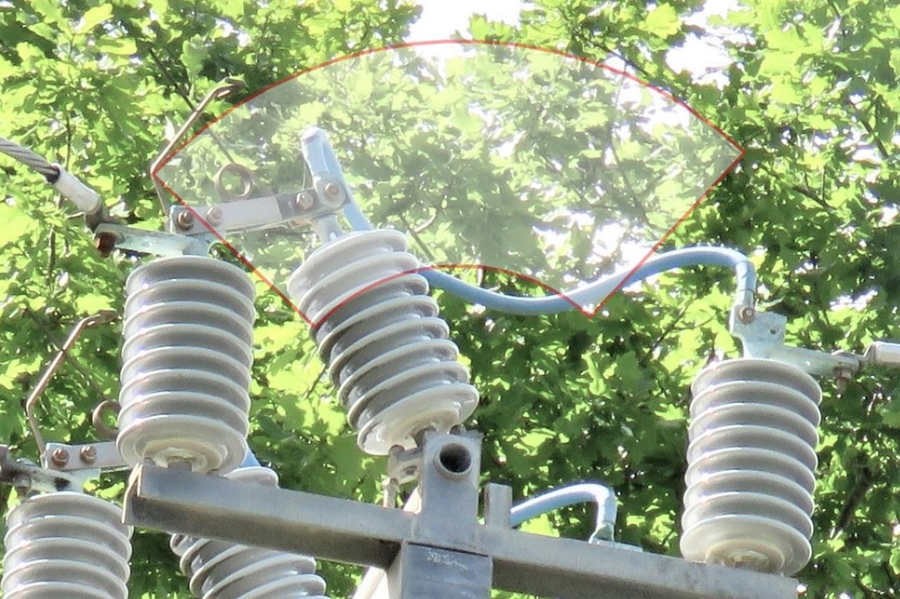
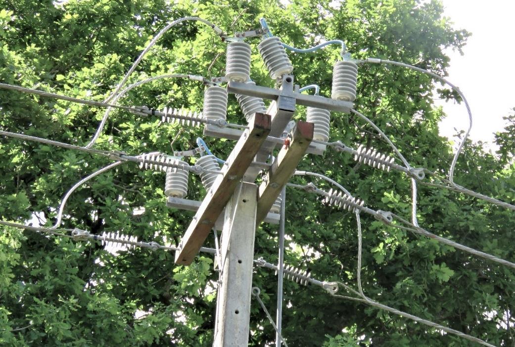
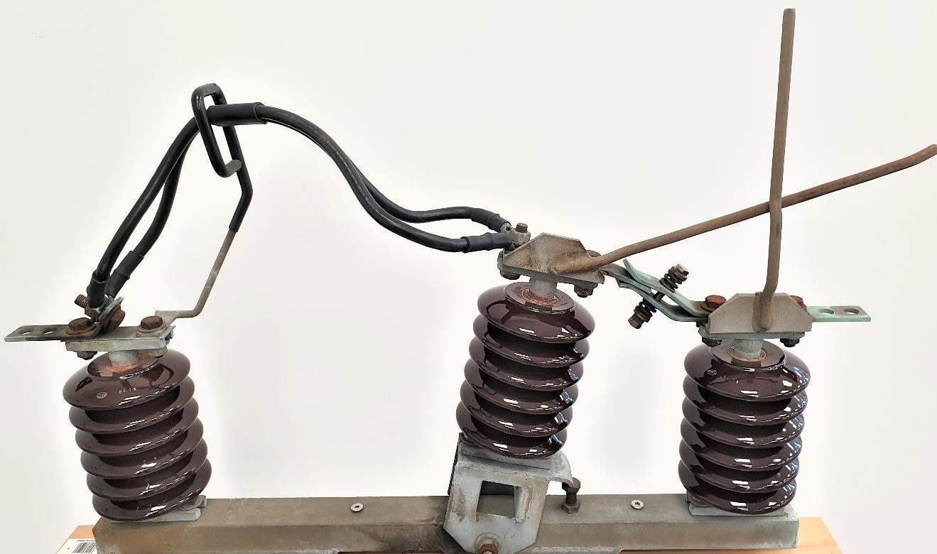
Conventional ABS has three (3) insulators per phase. The middle insulator rotates on an axis to make or break contact, while the other two insulators are stationary (fixed). The operating mechanism and the middle (rotating) insulators are heavy and have big inertia. The proper operation of ABS depends on the low-resistance contact between the moving contact (blade) and fixed contact (fork) because this contact carries a high load current
The key weakness of conventional ABS is in its inherited concept design of the main contacts (e.g. geometry of contacts and rotating insulator relative to each other), as follows:
• The middle rotating insulator, and the contact surfaces of the moving blade and fixed fork are in the same plane (e.g parallel to each other), and they move relative to each other in the same (vertical) plane.
And that causes the problem:
• Any perpendicular vibration of the operating mechanism and/or the rotating insulator causes the contact surfaces between the blade and fork to move (vibrate) relative to each other.
• This vibration affects the contact surfaces on both sides of the contact blade as follows:
o Fretting wear and corrosion on the contact surfaces on one side,
o Micro-arcing and pitting on the other side due to increased contact resistance
o This process alternates from one to another side and is self-perpetuating
o It is further exacerbated by the environmental conditions e.g. moisture, saltyair, contaminants, and thermal expansion, which accelerate galvanic processes
As proof – it has been observed during maintenance of conventional ABS that the contacts are eroded with a lot of pitting on contact surfaces, burned due to arcing, and misaligned
Lateral
2.1
Failure Mechanism of the contacts of conventional ABS
“
Fretting corrosion is one of the most important failure mechanisms for separable contacts with base-metal materials.” [1]
2.1.1 Analogy with bus-stab contacts in substations
There is a direct analogy between the failure mechanisms of the main contacts of the conventional ABS and the bus-stab contacts on busbars in substations. A bus-stab contact is similar in shape and function to the ABS’s blade-fork contact. The main difference is:
• The cause of vibrations is different (in most cases)
• The ABS contact between the blade and fork carries full load current, while there is no load current through the bus-stab contact if it is used as mechanical support only.
• The failure mechanisms of bus-stab contacts are well-researched and documented, while the technical papers on failure modes of ABS contacts are scarce
Note: A busbar stab is a fork-shaped (also called ‘bus fingers’) spring-loaded mechanical support for the busbar, which can also serve as an electrical connection.
Let’s discuss the failure mechanism of a bus-stab contact if the busbar stab is used as mechanical support only. There is evidence of fretting corrosion and damage to bus-stab contacts under normal operating conditions, caused by vibrations
As per Braunovic et al. [2], the bus-stab contacts are exposed to three types of vibrations:
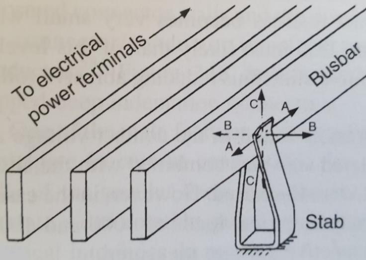
1) Slow slide motion between contact surfaces due to variations in electrical load (e.g. thermal expansion/contraction), visible as burns on the busbar. (See A-A motion in Fig.3)
Note: These motions are small on ABS contacts and therefore not critical for ABS.
2) Electromagnetically induced vibrations due to heavy currents flowing in adjacent busbars. (See B-B motion in Fig.3) They can cause busbar displacement of the order of 20 µm perpendicular to those induced by thermal expansion. Note: The ABS contacts are exposed to vibrations of similar amplitude and frequency
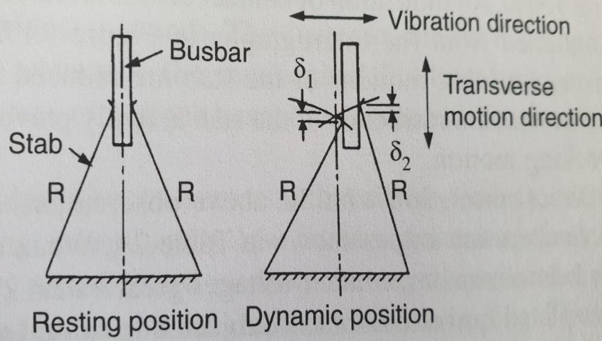
3) Fretting motions (transverse displacements) perpendicular to both thermal and electromagnetically induced vibrations. (See C-C motion Fig.3, Fig.4). As the busbar moves to the right from its neutral (resting) position, the stab’s two contacts are forced to move in a transverse direction. One contact moves upward and the other downward along thebusbar Whenthebusbarmoves to theleft,thestabcontacts reversetransverse motion. The frequency of rubbing transverse movements is 100 Hz (in a 50 Hz system).
As a result, there is fretting wear on contact surfaces resulting in pitting, erosion, and burning of contact surfaces, increased contact resistance, overheating, and contact failure.
Fig. 3 – Typical arrangement of busbar on a stab that is used as a mechanical support in substations. Arrows show the direction of motions acting on bus-stab contacts:
o A-A Slow-slide motions due to thermal expansion;
o B-B Motions due to electromagnetically induced vibrations;
o C-C Fretting motions (transverse displacements) arising from surface micro-slips associated with small-scale oscillatory motions due to B-B vibrations
(Ref: Braunovic at all. [2] - Fig. 7.16)
For a typical 400 A bus under normal electrical load, the relative displacement of bus-stab contacts due to transverse motions is less than 25 µm [2]. However, due to the repetitive nature of rubbing movements, it causes major material fatigue and fretting wear.
As per Braunovic et al. [2], the time to failure is much reduced if the contacts are exposed to vibrations of approx. 100 Hz and relative slide motions of 5 µm or more. The fretting wear further exposes the contacts to weather elements, contamination, and total failure This failure mechanism is similar to fretting wear on transmission lines exposed to Aeolian vibrations.
2.1.2 Main electrical contacts in conventional


The same failure mechanism applies to the contacts of conventional ABS. The only difference is in what causes vibrations. However, the consequences are much worse because:
• The ABS contacts carry a full load current
• When the blade moves to the right from its resting position, the fork (finger contact) on that side moves upward (Fig.5), resulting in fretting wear (as with the bus-stab case).
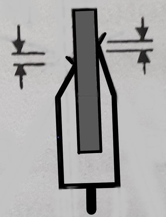
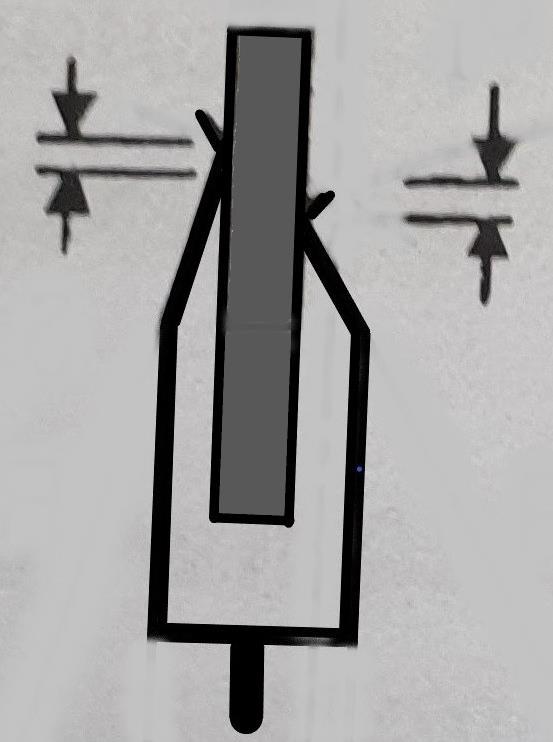
• On the other side, the finger contact moves downwards. The contact pressure is reduced due to the lower spring effect, resulting in increased contact resistance and more micro arcing, burning, pitting, and erosion. This process is self-perpetuating.
Fretting movement. Also, area of reduced contact pressure, resulting in microarcing, pitting, and erosion
Note: 5 µm is enough to cause fretting wear and damage
Therefore, it can be said that the conventional ABS design is imperfect, especially if it is exposed to vibrations and harsh environmental conditions. It will ultimately end up in high maintenance and reduced service life.
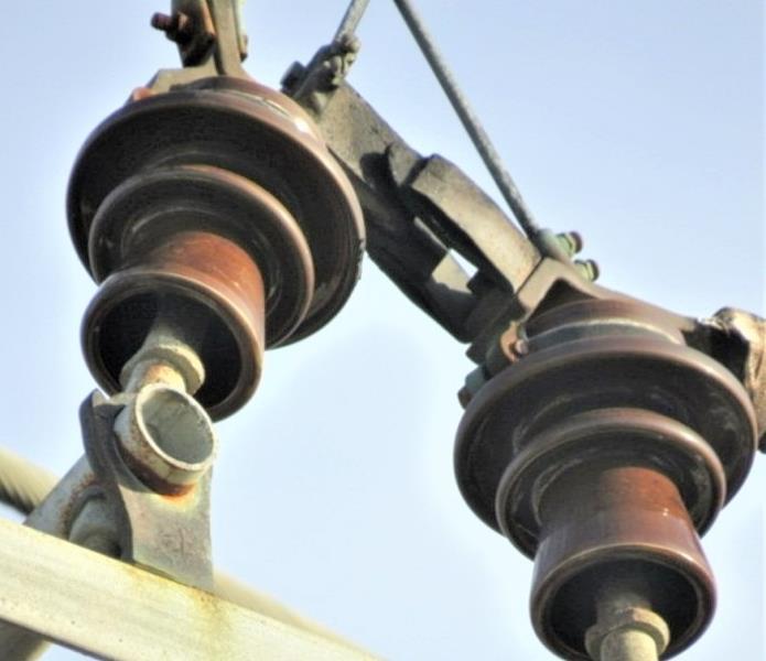
Heavy arcing, fretting corrosion, pitting, erosion
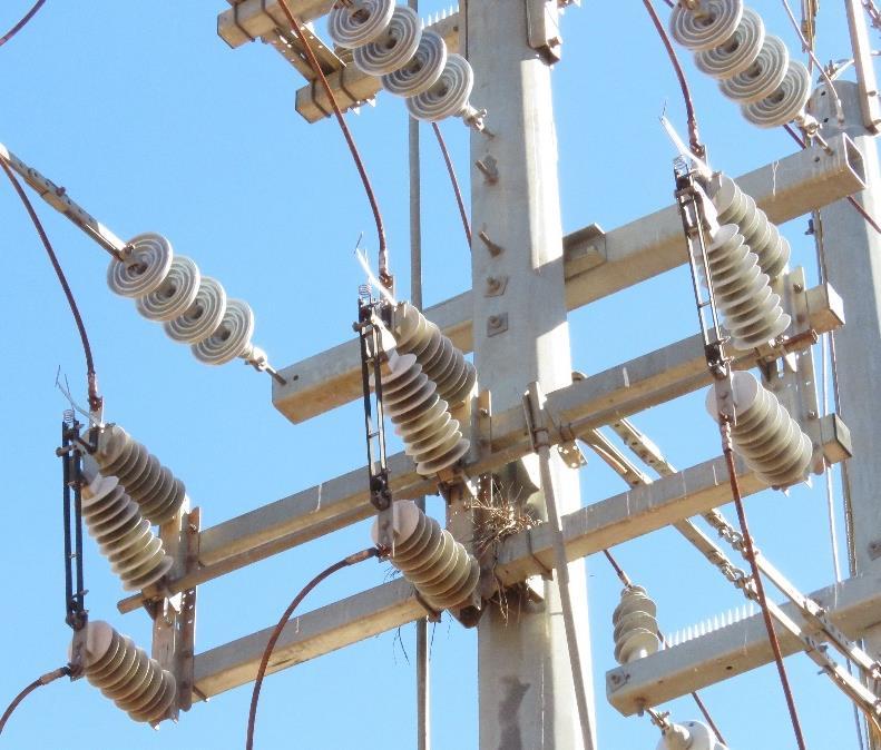
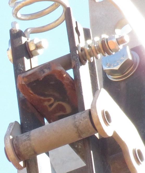
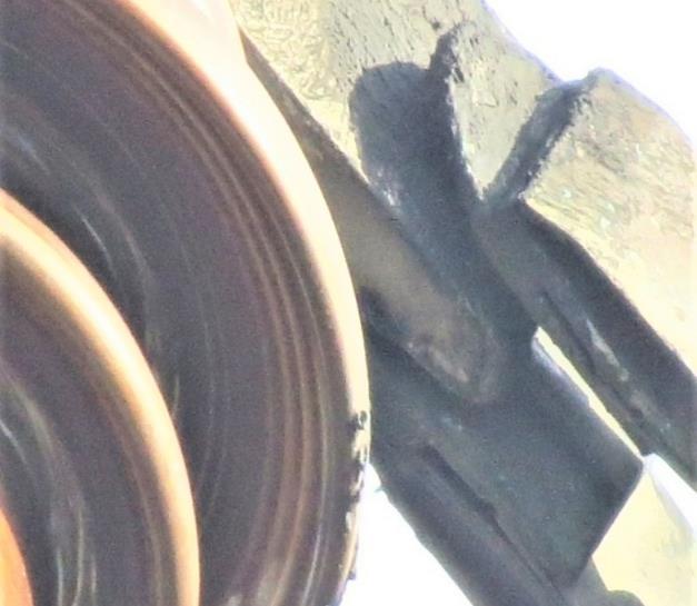
Heavy arcing, pitting, erosion
2.2 Why are there relative movements (vibrations) between the fixed part of the ASB assembly and the moving insulator with the contact blade?
Themovinginsulatorrotatesonashaftaroundanaxiswithabushing(asleevebearing). The typical radial clearance of bushings is 0.05 - 0.10 mm For comparison, the average human hair is about 0.016 to 0.05 mm thick. However, even this small clearance can result in shaft deflection, runout, vibration, and axial motion, depending on applications. [3]
The problem is further exacerbated if the bushing is corroded.
If the middle ABS insulator is exposed to vibrations, and if the bushing radial clearance is 5 µm, it would produce at the top of the insulator (at approx. 330 mm distance) the lateral displacement of the blade of approx. 1.5mm. It will in turn produce the transverse motion of contacts of approx. 7.5 µm which sets up a perfect condition for fretting movement and wear.


2.3 What can cause vibrations that affect contacts of conventional ABS
• Self-induced vibrations by ABS operation (closing and opening):
o As the blade slides between the two prongs of the fork – any left/right vibration of the operating mechanism and insulators will cause the contact surfaces to become loose to each other on one or the other side.
o Whenthecontactismade,inthestationarystate,thereisacurrentgoingthrough this contact. Any vibration will form a small gap between the contact surfaces.
• Vibrations induced by the operation of other hardware on the same line
• Mechanical vibrations induced by regular winds and storms that face high resistance (e.g. poles and other supporting structures, pole-mounted hardware like ABS assembly with a relatively large surface, etc.)
• Aeolian vibrations (10 to 120 Hz) are transferred from the OH conductors to the pole hardware. The most damaging frequencies of Aeolian vibrations are around 60 Hz.
• Mechanicalvibrationsfromthepassingtraffic.MostABSsareonpolesalongtheroads, typically at intersections, where vehicles introduce various vibrations. A typical car engine's crankshaft rotates at several thousand RPM. At 6,000 RPM, it still corresponds to a vibration frequency of 100 Hz [4], which is then transferred to adjacent structures.
• Furthermore, many vibrations are introduced by irregularities of the road surface [5], or via loose soil on reclaimed land
2.4 In summary - why do vibrations affect the conventional ABS?
The ABS contacts are separable connections (not fixed, not bolted together). They are held together by spring action which is not strong enough to prevent the relative movement of contacts (e.g. between the blade and fork). In conventional ABS design, the blade moves against the finger contacts and hits it alternately under vibrations:
• It creates transverse fretting movement on one side and slightly less on the other
• It intermittently opens a small gap on another side, causing arcing, pitting, and erosion
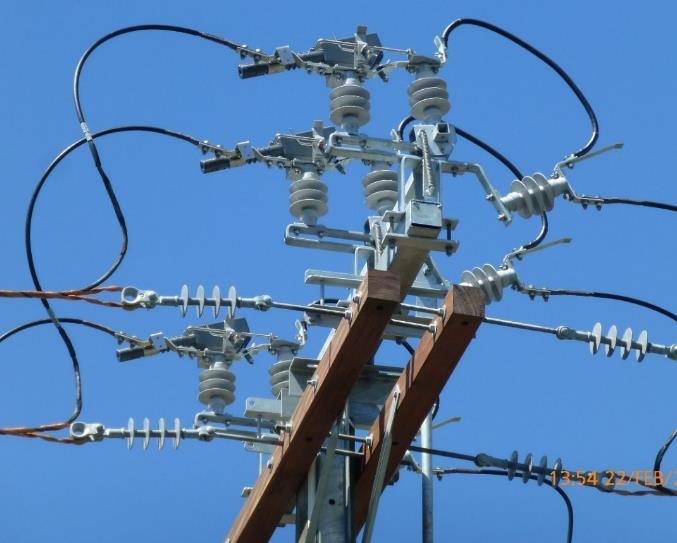
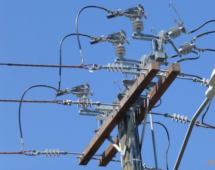
• The vibration force acts directly against the spring The spring is designed to compensate and adjust contact pressure in a stationary (resting) state, it is not designed nor capable to accommodate vibrational movements which are too fast
3. New design of ABS (Note: New to New Zealand)
3.1 Why vibrations do not affect the new ABS design?
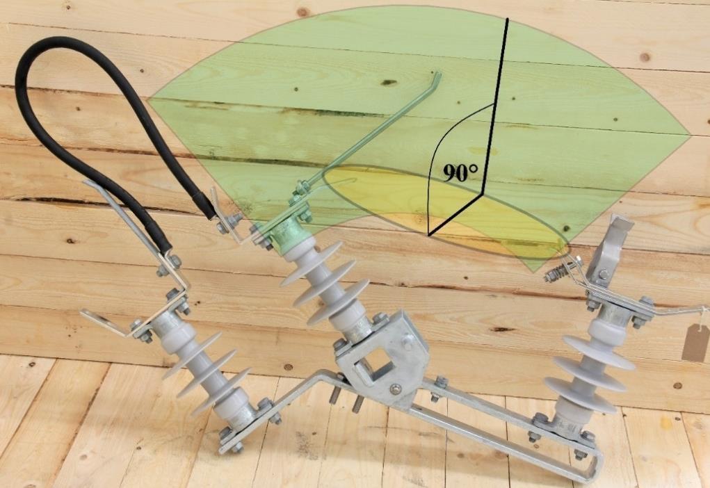
In the new design, the blade vibrations do not move against the finger contacts. The blade moves in parallel with finger contacts (e.g. it slides between contacts), and there is no fretting movement, or it is negligible. In other words, the vibration force does not act directly on the spring, andtherefore can not open thegap,so thecontact staystight. The newdesign eliminates the fretting transverse motion between the blade and fork.
Fig. 11 – The contacts of the new ABS design do not require regular maintenance nor re-alignment. Once pre-set in the factory, the only recommended maintenance is a visual inspection every 8 years
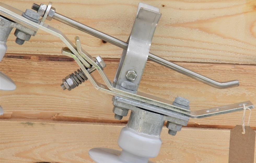
The insulator moves (vibrates) in vertical (‘green’) plane
The contact surfaces move in horizontal (‘yellow’) plane
Fig. 12 – New ABS design. The middle insulator and main contacts (blade and fork) are not in the same plane. They are in two different planes at 90° from each other. Therefore, any lateral movement (vibration) of the middle insulator will have no effect on the contact surfaces between the blade and fork. If the insulator vibrates, the blade moves as well, but it does not hit thefork, it slides betweenthe fork fingers e.g.theblade movesparallel with thefork fingers. Note: The slide distance is in µm and does not affect the contacts.
3.2 A simple proof of vibrations on OH lines - direct and indirect: The crews that maintain conventional ABSs have observed badly damaged ABS contacts even if ABS has never been operated e.g pitting, erosion, burns, heavy arcing (in ultrasonic and audible range), and misalignments after less than a year in service. The Author has observed this failure mode in real-life cases in different networks across Australasia during the acoustic inspections of OH networks. What is common in most of these cases is that ABSs have been exposed to some sort of vibrations. The existence of the vibrations can be confirmed either directly on indirectly, as follows:
Direct confirmation: These vibrations are subtle, in micrometers. However, human skin is sensitive to vibrations up to 1,000 Hz, with a peak sensitivity of around 250 Hz [6]. So, by simply putting a hand on a power pole or supporting structure in an area exposed to Aeolian vibrations, one can feel vibrations. A good example is the 33kV power lines in the Western Australian mining areas. In New Zealand conditions, by putting a hand on a concrete pole next to the road with the passing traffic, most people will be able to feel vibrations.
Indirect confirmation: There are many loosened nuts & bolts on OH power lines hardware. If there were no vibrations, they would simply not get loose. Although the initial loosening may start with thermal expansion, it will continue and self-perpetuate with mechanical vibrations.
4. Energy losses (thermal losses) from ABS during normal operation
All separable connections, including the ABS contacts, have a higher contact resistance than permanent connections. Therefore, they have higher energy losses. However, those connections that experience fretting wear, arcing, and erosion, have a major increase in contact resistance over time, resulting in significant heating and energy losses until they finally fail.
Traditional ABS with deteriorated contact presents such a case. When the traditional ABS contacts fail beyond repair, the ABS becomes inoperable. It then just sits there and continuously dissipates energy (heat), adding to the cost Therefore, due to energy losses alone, the true cost of traditional ABS over its service life can significantly exceed its original price. (Refer to [7] for the analogy).
In addition, the cost increases drastically in terms of SAIDI (e.g. as an Operational Constraint it can’t be operated when needed), feeder faults, and final replacements, not to mention the risk of bushfires ignited by molten metal from arcing contacts.
In comparison -the truecost ofthe newABS design overthesametime does not increase because it has stable contact resistance, and is a virtually maintenance-free device that offers high reliability over the entire service life
5. Discussion
The failure mechanism of conventional ABS contact under normal operating conditions has been attributed to the effects of fretting vibrations and micro arcing, as follows:
• Fretting movements and wear on one side of the separable contact, and
• Micro arcing and surface damage on the other side due to reduced contact pressure and increased contact resistance
These two effects alternate from one side to another according to the frequency of vibrations. This causes irreparable damage to both sides of the ABS contacts. That’s why frequent maintenance is needed, which involves cleaning contacts, greasing, and re-alignments Ultimately, this defect renders the ABS irreparable, and it has to be replaced.
On the other side, the new design of ABS has none of these problems, or it is negligible. That’s whythis design isvirtuallymaintenance-freee.g. nocleaning, greasing, orre-alignment.
5.1 The results speak for themselves
The ’new’ design has been around for more than 40 years. It successfully survived the test of time in harsh conditions. The maintenance of such an ABS was non-existent or minimal compared with New Zealand’s experience with conventional design.
Power utilities that adopted this design have experienced:
• Improved network reliability, resilience, SAIDI, and SAIFI
• Reduced risk of feeder faults due to failed ABS contacts
• Improved public and personnel safety e.g. no molten metal during operation
• More compact and modular design
• Easy to install – one person can carry individual components
6. Conclusions and recommendations
New Zealand distribution companies have thousands of ABSs based on traditional design. Most of them are along the roads, exposed to vibrations from passing traffic, winds, Aeolian vibrations, growing vegetation, sea spray, frequent storms, and unpredictable weather. There is a steady increase in the fault rate of ABSs in most networks over recent years, which have a significant impact on SAIDI/SAIFI.
The ’new’ ABS design stud the test of time in harsh environmental conditions in Europe for more than 40 years. There is no reason it would not suit New Zealand utilities as well.
References:
1. Neizen. J., at al.; Fretting Corrosion of Tin-Coated Electrical Contacts, IEEE Transactions on Components, Hybrids, and Manufacturing Technology ( Volume: 10, Issue: 1, Mar 1987)
2. Braunovic, M., Konchits,V.V., Myshkin, N.K.; Electrical Contacts – Fundamentals, Applications and Technology’ CRC Press, Taylor and Francis Group, 2007
3. Handling shaft deflection, runout, vibration, & axial motion, Kalsi Seals Handbook (2019)
4. Vibration from Car Engine During Morning Commute
https://endaq.com/pages/measurement-analysis-vibration-from-car-engine-duringmorning-commute
5. M. Agostinacchio at al.; The vibrations induced by surface irregularities in road pavements, Eur. Transp. Res. Rev. (2014) 6:267–275
6. Serhat.G, Kuchenbecker.K.; Free and Forced Vibration Modes of the Human Fingertip, Applied Science, MDPI, Article, 2021
7. Evaluating Efficiency and Losses of Various Circuit Protective Devices, White Paper AP08324002E, EATON, 2010
https://www.eaton.com/content/dam/eaton/markets/machinebuilding/whitepaper/circu it-protective-devices.pdf
8. Slade, P.G; Electrical Contacts – Principles and Applications CRC Press, Taylor and Francis Group, 2014
9. MÜLLER, P., at al.; Universität Stuttgart & Siemens AG – Germany, Current Characteristics of Serial and Parallel Low Current Arc Faults in Distribution Networks, CIRED, 21st International Conference on Electricity Distribution Frankfurt, Paper 0181 2/4, 6-9 June 2011, 10. Stojadinovic, G.; Ultrasonic defect detection for predictive maintenance of power lines and bushfire risk mitigation. Australian Utility Week Conference, Sydney. 2016
