Do we really need a semiconductive coating on ceramic post insulators?

Goran Stojadinovic, TransNet NZ, 4 June 2020
www.transnet.co.nz


Radio Frequency Interference (RFI) from distribution network insulators
• The insulators are essential components of any distribution network
• However, some of them can cause undesirable effects like Radio Frequency Interference (RFI)
• In most cases RFI in distribution networks come from:
• Pin insulators
• Multi-shell pin type insulators
• Some types of strain insulators
Note: RFI is caused by other equipment as well, but it is not a focus of this subject matter
What causes RFI on power lines
Radio interference from MV/HV insulators is caused mainly by:
1. Corona discharge (air ionization) at locations on the insulator where the air is ionized by excessive dielectric flux concentration
e.g. electrically overstressed air in the dielectric field; and
2. Intermittent leakage currents flowing through conducting contaminants on the insulating surfaces
Note: RFI can be also caused by:
• Damaged (faulty, cracked, or contaminated) insulator
• Loose or broken binding wire
• Incorrectly installed and untidy binder
The corona formation and radio interference often occur simultaneously even at 11kV level under right conditions
Let’s focus on Pin and Post insulators
What
• The metallic pin of the pin type insulators brings the ground point of the insulator very close to the phase
• Thus, that area is exposed to high electrical stress
e.g. there is a high concentration of equipotential lines which increase electrical field gradient
As a consequence, RFI is found in two places on many of the standard pin insulators, as follows:
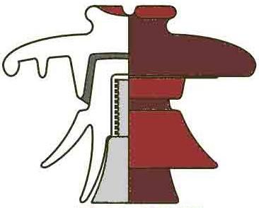
1. At points where the conductor and tie wire (binder) are not in very close (tight) contact with the insulator head and groove (e.g. if there is a gap)
2. At the contact between the metallic pin and the insulating material
makes pin insulators so predisposed to produce such a high rate of RFI
30
A solution to reduce the RFI from pin insulators
• Originally, the semi-conductive coating (RF – radio-free) was introduced for the pin insulators only because they were causing more RFI than any other insulators. Furthermore, there were more pin insulators in distribution networks than any other type of insulators.
• The main purpose of a semi-conductive coating on pin insulators is to redistribute the electrical field gradient and to prevent or minimize RFI
• This solution was reasonably successful for solving RFI problem, but could not solve the other issues with pin insulators
• Subsequently, the post insulators were introduced to gradually replace pin insulators to solve all or most of these problems and to provide a reliable and long-lasting service life
Can a standard ceramic post insulator without semiconductive coating cause RFI
It is highly unlikely that a standard ceramic post insulator (without semi-conductive coating or RF) will cause RFI, for the following reason:
• The metallic pin of the ceramic post-type insulators is located far away from the phase to cause an increase in electrical stress in the area where the conductor is attached
• In other words – there is no increase in the electrical field gradient
• Furthermore - there is no evidence that the RF coating makes any difference because there is simply no RFI from standard post insulators
Moreover - there is an indication that the RF coating on a ceramic post insulator:
• Can have a detrimental effect on its reliability and service life
• Can even contribute to RFI, as follows:
Detrimental
effects of RF-coated ceramic post insulators on bare conductors
• The RF coating distributes the electrical field along the surface of the head & groove of post insulator and reduces the number of electric field lines in the insulator head e.g. it reduces the electrical field stress in the insulator head
• However, at the same time it increases the number of electric field lines around the conductor and binder, and in the conductor insulating layer including the air gaps in the contact area
• Thus, in the case of covered conductors - there is PD through the conductor insulation and micro-arcing across air gaps between the conductor and insulator at the edges of contact area, which causes deterioration of conductor and its insulation
• In the case of bare conductors – a very similar process takes place. Every bare conductor and metallic binder has an insulating layer made of an oxide film and other contaminants. This layer acts as insulation between the conductor/binder and insulator head, which in the presence of increased electrical field (stress) can result in micro-arcing and increased ionization
• Increased ionization is always linked with an increase in the deterioration of materials
• Indeed, the FEA simulations and lab tests with accelerated aging of hardware have confirmed the findings (Ref #1)
Electrical field concentration around the radio-free and standard ceramic post insulators (Ref. #1)
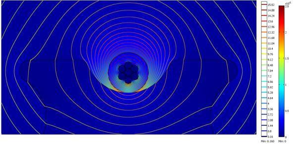
• The RF coating reduces the electrical field (stress) in the insulator head. Basically, it re-distributes the electric field lines on the semiconducting glazing and makes the electrical field in the insulator head uniform
• However, it increases the concentration of electric field lines between the conductor, conductor insulation, and the insulator groove, resulting in an increase of electrical stress (electrical field gradient)
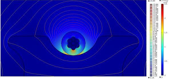
• Without the RF coating - there is a greater number of field lines crossing porcelain
• Therefore, there is a lower concentration of the electrical field between the conductor, it’s insulation, and the insulator groove, resulting in lower dielectric stress in that area
• The increased electrical field gradient in the insulator head does not affect the insulator performance because it is far away from the ground
Figure 7 - Study of electrical field around post type ceramic insulator P1 - RT radio-free.
Figure 8 – Study of electrical field on P1 ceramic insulator line post type without radio-treatment
Note regarding the study in Ref. #1
This study was originally conducted as a study of dielectric compatibility between covered conductors and various types of insulators
However, it is also highly relevant to bare conductors and other types of insulators because:
• The RF coating creates the increased electrical stresses on the conductor side (e.g. much greater concentration of electric field lines) regardless of the type of conductor (bare or covered)
• Bare conductors also have a layer of insulating material on the surface e.g. Al oxide film plus deposits of various contaminants
Note: That insulating layer is even more evident at the contact area between the insulator, conductor and binder due to reduced natural washing, the increased retention of moisture, and the associated galvanic processes
• There are also air gaps between the conductor/binder and insulator at the edges of the contact area
• The loose metallic binders create additional air gaps
• When such insulating layers and air gaps are exposed to the increased electrical field (stresses), there is an increased possibility of micro-arcing, ionization, and deterioration of conductor, binder and even the RF coating
• Therefore, the RF coating has a potential to reduces the lifetime of bare conductors as well, not only of covered conductors as per international experience:
International experience and real-life cases
South Korea:
• The entire KEPCO’s distribution network at 22.9 kV is covered e.g. CCT - covered conductor thick
• All line post ceramic insulators are without RF coating
Note: KEPCO network is officially the best and the most reliable network in the world, with the SAIDI of 8.9 minutes
Brazil: Brazil has banned RF coated post insulators in their OH compact networks:
‘’All previous experiences carried out in Brazil condemned the use of radio-free insulators for the application to covered conductors compact networks… the presence of semi-conductive glaze, applied to the head of radio-free insulators, reduces the lifetime of covered conductors’’ (Ref. #1)
Why would OH networks with bare conductors be much different from above?
Indeed, there are reported cases of RFI from RF-coated ceramic post insulators in networks with bare OH conductors, as follows:
NZ case study: Three RF-coated ceramic post insulators with strong Radio Frequency Interference
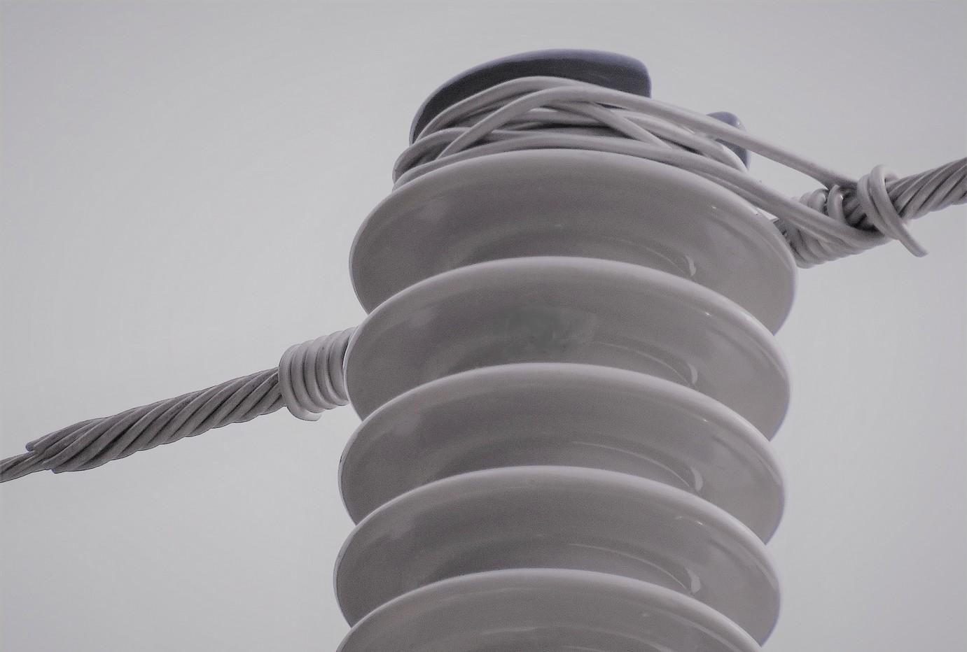
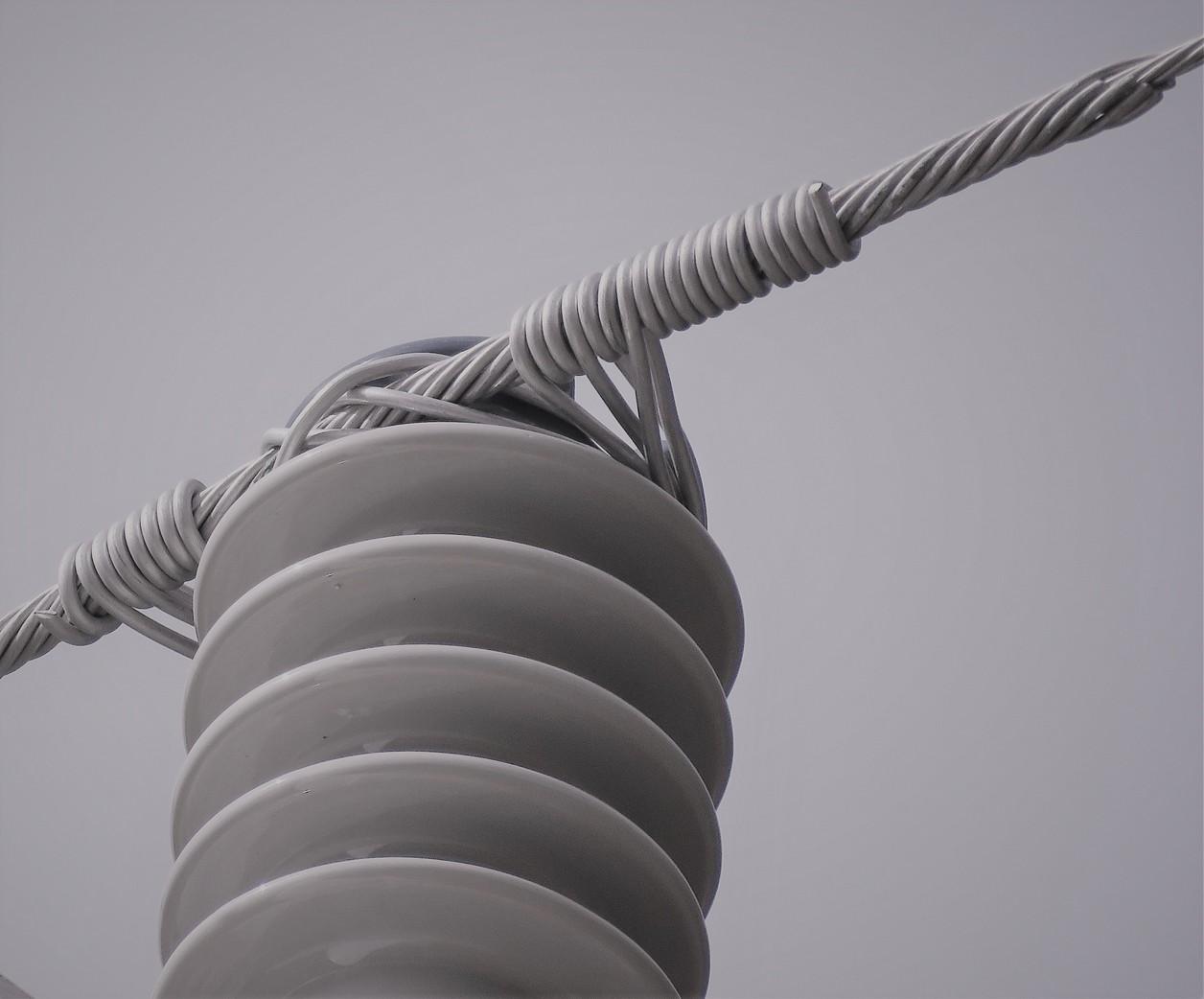
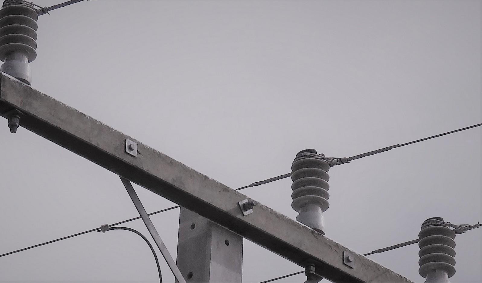
Source of strong RFI
All three (3) insulators were RF-coated ceramic post insulators – installed to prevent RFI
• However, all three insulators were emitting high RFI from the tie wire (binder) area
All three binders were loose, messy, and with sharp ends; also, all three armor-rods were untidy and with sharp ends
• However, the source of RF interference was pinpointed to the area around the head of the insulator & binder in all cases
Instead to help with reducing RFI, it seems that the RF-glazing contributes to it:
• RF-glazing rises the electrical stress on the insulator head surface and exacerbates the formation of RFI due to binding issues
Note that all three conductors were installed sideways, not in the groove, however, they were still fully sitting in RF-coated area
Conclusion
• The standard ceramic line post insulators without semi-conductive coating stood the test of time as the most reliable and long-lasting insulators for distribution network
• Introducing RF coated post insulators looks more like a knee-jerk reaction to a perceived but non-existent problem.
• In reality - there is no evidence that the RF coating on ceramic post insulators makes any difference or improves anything because there is simply no RFI caused by post insulators
• Moreover – there is an indication that the RF coating on ceramic post insulators can have a detrimental effect on bare conductor and bonders, as it has on covered conductors
• Not only that – it seems that the RF-glazing on ceramic post insulators can also contribute to RFI in the case of incorrect installation of binders and armor-rods
Note: Currently, there are not enough studies in this area. It might take time to realize how RF-coated ceramic post insulators badly affect bare conductors in the filed. Unfortunately, when it happens, it will be too late and very costly.
Recommendations
• The distribution networks should be discouraged to use the RF-coated ceramic post insulators unless there are a specific reason, application, and proven benefits
At the end of the day - why introduce something that:
• Addresses a non-existent problem
• Isn’t necessary e.g. without any other proven benefits
• Can reduce reliability and service life of bare conductors and binders by compromising their electrical and mechanical integrity
• Can even contribute to RFI instead of reducing it
• Has a potential to create pre-fault conditions with accelerated hardware deterioration which would eventually turn into feeder faults
The final decision is yours!
Questions and Answers Goran Stojadinovic, MCE, MEng(El) Product and Innovation Manager, TransNet NZ +64 21 435 753 / gorans@transnet.co.nz
References
1) ‘Porcelain Insulators and Covered Conductors – A Problem of Dielectric Compatibility’ by Manuel Martinez Universidade Federal de Itajubá (UNIFEI)
2) ‘The Line Mechanic’s and Cable Jointer’s Handbook’, EEA, New Zealand, 2013
3) ‘Radio Interference from Insulator Corona’ by F. o . McMILLAN, Oregon
4) Lefort, C., Barreira, M. L., Using radio frequency and ultrasonic antennas for inspecting pin-type insulators on medium-voltage overhead distribution lines., Ingeniería e Investigación. Vol. 33, No. 2. August 2013, pp. 63 – 69.)
