
D7G TRACK-TYPE TRACTOR

 START BY:
a) remove sprocket assemblies
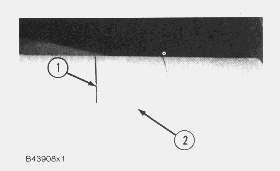
1. Remove bolts (1) that hold final drive case (2) in position.
START BY:
a) remove sprocket assemblies
1. Remove bolts (1) that hold final drive case (2) in position.
2. Install two 5/8"-11 NC guide bolts (3). Install three 1/2"-13 NC forcing screws (4).
3. Tighten the forcing screws evenly until the case is approximately .25 in. (6.4 mm) away from the steering clutch case.

4. Install a piece of wire around the guide pins to hold the idler pinion in place.
NOTICE
The wire is to keep the planet carrier in position so it will not fall from the steering clutch case when the final drive case is removed.
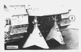
5. Tighten the forcing screws until tool (A) and a hoist can be fastened to final drive case (2). Remove final drive case (2). The weight is 280 lb. (127 kg.)


 6. Remove the plugs for the dowels that hold race and roller assemblies (5) and (6) in place with tooling (B).
7. Remove the dowel for race and roller assembly (6) with a 10-32 screw (7). Remove the dowel for race and roller assembly (5) with a 1/4"-20 NC bolt.
8. Use tooling (C) and remove race and roller assemblies (5) and (6) from the final drive case.
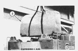
9. Install tool (D) on gear (8). Fasten a hoist. Remove gear (8) and hub (9) from the sprocket shaft. Put the gear and hub on wood blocks. The weight of the gear and hub is approximately 350 lb. (159 kg)
6. Remove the plugs for the dowels that hold race and roller assemblies (5) and (6) in place with tooling (B).
7. Remove the dowel for race and roller assembly (6) with a 10-32 screw (7). Remove the dowel for race and roller assembly (5) with a 1/4"-20 NC bolt.
8. Use tooling (C) and remove race and roller assemblies (5) and (6) from the final drive case.
9. Install tool (D) on gear (8). Fasten a hoist. Remove gear (8) and hub (9) from the sprocket shaft. Put the gear and hub on wood blocks. The weight of the gear and hub is approximately 350 lb. (159 kg)
Typical Example
10. Remove bearing cone (11) from the hub with tooling (E).

11. Remove nuts (10) and locks from bolts (12). Remove bolts (12) with a soft punch and hammer.

Typical Example
12. Use a nylon strap and a pin or bolt with a length that is longer than the inside diameter of the hub to fasten a hoist to the hub. Remove hub (9) from gear (8). The weight is 218 lb. (99 kg)
13. Remove bearing cup (13) if necessary.

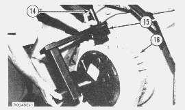
14. Remove the wire from the gear and pinion. Fasten a hoist and remove gear (14) and the pinion from the steering clutch case. The weight is 120 lb. (54 kg).

15. Remove bearing race (15) with tooling (F) from the pinion shaft.
NOTE: Step 16 is for later models only with a two piece pinion and gear assembly. Earlier models, the pinion and gear are one piece.

NOTICE
Too much pressure on the pinion shaft can cause damage to the gear.
Typical Example
16. Remove pinion shaft (16) from the gear as follows:
a) Put the gear and pinion shaft in a press as shown.
b) Put a small amount of pressure on the pinion shaft with the press. Push the ring in the groove on the pinion shaft with a hammer and punch. The ring will stay in the groove because of the pressure on the pinion shaft.
c) When the ring is completely in the groove, the pinion shaft will slide out of the gear. The weight of the pinion is 85 lb. (39 kg).
17. Remove bearing race (17) from the pinion shaft with tooling (F).
18. Drain the oil from the steering clutch and bevel gear case.


 19. Bend locks (18) down. Remove bolts (19) and locks (18).
20. Install two 1/2"-13 NC forcing screws (21) in bearing cage (20). Tighten the forcing screws evenly and remove bearing cage (20) from the steering clutch case.
21. Use a 1/4"-20 NC bolt (22) to remove the dowel from cage (20).
22. Remve race and roller assembly (23) from bearing case (20) with tooling (C).
19. Bend locks (18) down. Remove bolts (19) and locks (18).
20. Install two 1/2"-13 NC forcing screws (21) in bearing cage (20). Tighten the forcing screws evenly and remove bearing cage (20) from the steering clutch case.
21. Use a 1/4"-20 NC bolt (22) to remove the dowel from cage (20).
22. Remve race and roller assembly (23) from bearing case (20) with tooling (C).
23. If necessary, remove bearing race (24) with tooling (F) from the pinion.

Install Final Drive Cases, Gears, Idler Pinions And Bearings
1. Heat bearing race (1) to a maximum temperature of 275°F (135°C). Install bearing race (1) on the pinion shaft.


NOTICE
All race and roller assemblies with snap rings must be assembled with the snap ring next to the gear teeth.


 2. Lower the temperature of roller and race assembly (3). Make sure the hole in the race and roller assembly is in alignment with the hole in cage (2) and install race and roller assembly (3).
3. Install dowel (4) to hold the race and roller assembly in the cage. Use a 1/4"-20 NC bolt (5) to install the dowel.
4. Put 7M7260 Liquid Gasket Material on the contact surfaces of the cage and steering clutch case. Put cage (2) in position in the steering clutch case. Make sure the oil groove next to the race and roller assembly is at the bottom.
5. Install four locks (6) and eight bolts (7) that hold the cage in place. Bend the locks up.
2. Lower the temperature of roller and race assembly (3). Make sure the hole in the race and roller assembly is in alignment with the hole in cage (2) and install race and roller assembly (3).
3. Install dowel (4) to hold the race and roller assembly in the cage. Use a 1/4"-20 NC bolt (5) to install the dowel.
4. Put 7M7260 Liquid Gasket Material on the contact surfaces of the cage and steering clutch case. Put cage (2) in position in the steering clutch case. Make sure the oil groove next to the race and roller assembly is at the bottom.
5. Install four locks (6) and eight bolts (7) that hold the cage in place. Bend the locks up.
6. If a separation of the idler gear and pinion was made, install a new retainer in the pinion. Install the gear over the pinion so the deep chamfer is used to put the retainer under compression. Make sure the retainer is engaged in the groove of the gear.
7. Heat bearing races (8) to a maximum temperature of 275°F (135°C) and install them on each end of pinion (9).


8. Put 5P960 Multiurpose Type Grease in the roller assemblies to hold the rollers out for installation of gear (10) and pinion (9). Fasten a hoist and install gear (10) and pinion (9) in the steering clutch case.
9. Fasten a wire around the guide bolts, gear (10) and pinion (9).

NOTE: The wire will hold the gear and pinion in position until the final drive case is installed.
10. Fasten a hoist to hub (11) and put it in position in gear (12). Install the bolts (from the top side), locks and nuts that hold the hub and gear together.
11. Heat bearing cone (13) to a maximum temperature of 275°F (135°C). Install bearing cone (13) on the hub.
12. Lower the temperature of bearing cup (14). Install bearing cup (14) in the steering clutch case. Make sure the bearing cup is tight against the surface of the counterbore.

13. Use tooling (A) and a hoist and put the hub and gear in position on the sprocket shaft.
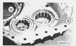
14. Lower the temperature of race and roller assemblies (15) and (16). Make sure the hole in the race and roller assemblies are in alignment with the dowel holes in the case. Install the race and roller assemblies (15) and (16) in the final drive case.

Typical Example
15. Install the dowels and plugs in final drive case (17) to hold the race and roller assemblies in place. Put 5P960 Multipurpose Type Grease on the roller assemblies to hold the rollers out to prevent damage to parts when final drive case (17) is installed.
16. Install tooling (B) and a hoist to the final drive case. Put 7M7260 Liquid Gasket Material on the contract surfaces of the steering clutch case and final drive case.
17. Put the final drive case on the guide bolts and remove tooling (B) and the wire used to hold the pinion.

18. Push final drive case (17) against the steering clutch case. Install bolts (18) and washers that hold final drive case (17). Tighten the bolts to a torque of 200 ± 20 lb.ft (270 ± 25 N·m).

19. Fill the steering clutch case and final drive cases with oil to the correct level. See Maintenance Guide.
END BY:
a) install sprocket assemblies

Copyright
All Rights Reserved. Private
For SIS Licensees. Mon Jul 26 22:39:45 UTC+0800
1993 - 2021 Caterpillar Inc.
Network
2021
Previous Screen
Product: TRACK-TYPE TRACTOR
Model: D7G TRACK-TYPE TRACTOR 45W
Configuration: D7G TRACTOR / DIRECT DRIVE / 45W00407-UP (MACHINE) POWERED BY 3306 ENGINE
Disassembly and Assembly
D7G TRACTOR POWER TRAIN
Adjustment For The Final Drive Bearings
SMCS - 4059-11; 4059; 4075-12
Adjustment For The Final Drive Bearings

Shutdown SIS
Media Number -SENR7119-02 Publication Date -01/02/1983 Date Updated -14/10/2004 SENR71190014
1. Loosen bolt (2) and open track adjuster access panel (1)
The adjuster cylinder for the track is under high hydraulic pressure. Do not visually inspect the relief valve to see if grease is released when it is open. Look to see that the track has loosened. Use this warning any time the tracks are loosened or tightened.
a) Turn relief valve (3) one turn counterclockwise to permit grease to be released from the vent hole below the relief valve. If the track does not loosen, go to Step b.

b) Turn fill valve (4) one turn counterclockwise to permit grease to be released from the vent hole below the fill valve. If the track still does not loosen, start the machine and move it forward and backward. If grease is still not released go to Step c.
c) Put a 3 in. diameter by 3.5 in. long (76.2 mm) diameter by (88.9 mm) long slug in position on the sprocket teeth. The slug must be in a position where it will make contact with the track bushing when the sprocket is turned in reverse. Move the machine to the rear. This will put tension on the track and move the front idler and track adjuster to the rear against the force of the recoil spring. This will push grease out of the vent holes.
 2. Loosen the track as follows:
Typical Example
3. Lift the machine so the track will clear the floor and install tooling (A) and (B) under the machine. The sprocket assembly must turn while the adjustment to the final drive bearing is made.


4. Remove guard (5) from the track roller frame.
5. Remove cap (6) from the support.
6. Remove gasket (7). 7. Remove bolt (8) and the nut. Remove lock (9).NOTE: All the parts must be clean. The bearings must have final drive compartment oil on them. The adjusting nut must turn freely on the threads and the bearing cage must move freely in the holder.
8. Install tooling (C) as follows:
a) Install trunnion group (12) [use holes (Y)] on the track roller frame support assembly (10). The trunnion arm with the identification "X" must be fastened to the first hole with threads clockwise from grease fitting (11). See decal (13).
b) Install driver group (15) on the trunnion. Pin (14) must be in the retracted position as shown.


 c) Push pin (14) down between two lugs on adjusting nut (16).
9. Install tooling (D). Start the machine and turn the sprocket slowly while adjusting nut (16) is tightened with tooling (C) and (D) to a torque of 2500 ± 300 lb.ft. (3380 ± 410 N·m).
10. Tighten nut (16) in a counterclockwise direction. On the left side of the machine, the nut is tightened in a counterclockwise direction also.


11. Remove the 9S7351 Torque Wrench and install a ratchet wrench. Turn adjusting nut (16) clockwise (about six to ten lugs) to lower the torque to less than 350 ± 10 lb.ft. (475 ± 14 N·m).
NOTE: If it is not possible to get a torque below 350 ± 10 lb.ft. (475 ± 14 N·m) after the adjusting nut is loosened, a separation of the tracks must be made to make the adjustment of the bearing.
12. Remove the 5P3508 Torque Multiplier and install tooling (E). Tighten adjusting nut (16) to a torque of 350 ± 10 lb.ft. (475 ± 14 N·m).
13. Move the driver group out of the way and put a mark (18) on adjusting nut (16) and holder assembly (17) in alignment with each other. Put a mark (19) on holder assembly (17) counterclockwise from mark (18) [distance (Z)] that is 5.84 ± .06 in. (148.3 ± 1.5 mm) from mark (18).

14. Install driver group (15) on the shaft of the trunnion group.
15. Install torque multiplier (20) [part of tooling (D)] and tighten the adjusting nut until marks (18) and (19) are in alignment.


NOTICE
If necessary, tighten adjusting nut (16) more to install lock (9) in one of the notches of the adjusting nut. Do not loosen adjusting nut (16).
16. Install lock (9) and the bolt (8) and nut that holds it in place.

17. Remove tooling (C).
18. Install the gasket and cap (6).
19. Install guard (5).
20. Remove tooling (A) and (B) from under the machine.


21. Tighten relief valve (3) and fill valve (4) to a torque of 25 ± 5 lb.ft. (35 ± 7 N·m).
22. Make an adjustment of the track. See SPECIFICATIONS.
23. Close track adjuster access panel (1) and tighten bolt (2).
 Typical Example
Copyright 1993 - 2021
Inc. All Rights Reserved. Private Network For SIS Licensees. Mon Jul 26 22:40:41 UTC+0800 2021
Caterpillar
Previous Screen
Product: TRACK-TYPE TRACTOR
Model: D7G TRACK-TYPE TRACTOR 45W
Configuration: D7G TRACTOR / DIRECT DRIVE / 45W00407-UP (MACHINE) POWERED BY 3306 ENGINE
Disassembly and Assembly
D7G TRACTOR POWER TRAIN
Sprocket Shafts

SMCS - 4058-11; 4058-12
Remove Sprocket Shafts
START BY:
a) remove final drive cases, gears, idler pinions and bearing.
Shutdown SIS
Media Number -SENR7119-02 Publication Date -01/02/1983 Date Updated -14/10/2004 SENR71190015
1. Remove ring (1) and the pin from nut (2).
Do not remove nut (2) from the sprocket shaft.
2. Loosen nut (2) with tool (A) until there is a clearance of .125 in. (3.2 mm) between the nut and the steering clutch case.


3. Install tooling (B) and remove sprocket shaft as follows:
a) Install 5P5215 Adapter (3) on sprocket shaft (4) until all the threads are engaged.
b) Install 5P5207 Stud (5) in adapter (3) and turn it all the way into the adapter.
NOTE: Install sleeve (7) with (slot) opening (8) away from the bevel gear case as shown.
c) Put 5S1430 Sleeve (7) over stud (5) until the sleeve makes contact with bevel gear case (9).
d) Install 9H3992 Head (6) [or 7F5283 head] over stud (5) and into the end of sleeve (7).
e) Put 5P5201 Cylinder (11) on stud (5) and against head (6). Install nut (10). Connect the 5P3100 Pump Group to the cylinder.
f) Hold sleeve (7) and head (6) in alignment and put enough force on the sprocket shaft to loosen the sprocket shaft from the taper.
Be sure the piston of cylinder (11) is retracted before the tooling is removed.

g) Remove tooling (B). Fasten a hoist to the sprocket shaft. Remove nut (2). Remove the sprocket shaft. The weight is approximately 185 lb. (84 kg).

Install Sprocket Shafts
1. Fasten a hoist to the sprocket shaft and put it in position in the steering clutch case. Push the shaft in the case as far as possible by hand.

Be sure the threads in the bevel gear case are not damaged. Install the 1P3054 Adapters in the bevel gear case so the shoulder of the adapter is against the bevel gear case. After the shoulder of the 1P3054 Adapter comes in contact with the bevel gear case, the adapters can be tightened a maximum of 1/8 turn or loosened a maximum of 3/8 turn to put the adapter in the correct position so the remainder of tooling (A) can be installed. When the remainder of tooling (A) is installed, do not let the weight of the tooling or hoist put a load on the 1P3054 Adapters. Keep tooling (A) level.

Typical Example
Thank you very much for your reading. Please Click Here. Then Get COMPLETE MANUAL.NOWAITING

NOTE:
If there is no response to click on the link above, please download the PDF document first and then clickonit.
GET MORE OTHER MANUALS https://www.aservicemanualpdf.com/ GET MORE OTHER MANUALS https://www.aservicemanualpdf.com/
2. Fasten tooling (A) to sprocket shaft (1) as shown.


3. Install the sprocket shaft with a force of 55 to 60 ton (490 to 535 kN). Install nut (4) on the end of the shaft and tighten the nut to a torque of 750 ± 50 lb.ft. (1020 ± 70 N·m) with tool (B) while the force is still on the shaft. Release the pressure on tooling (A).
4. Measure distance (C) from the inner edge of the holder assembly to the bottom of the counterbore for the inner bearing cup. This dimension must be 17.258 ± .062 in. (43.84 ± 0.16 cm) for standard machines and 21.258 ± .062 in. (54.00 ± 0.16 cm) for low ground pressure machines.
5. Fasten nut (4) in position as follows:
a) Make a .368 in. (9.35 mm) hole in one of the grooves in nut (4). Drill the hole through the nut and .56 in. (14.22 mm) deep in the sprocket shaft.
b) Install pin (3).
c) install ring (2).
END BY:
a) install final drive cases, gears, idler pinions and bearings.
Shutdown SIS
Previous Screen
Product: TRACK-TYPE TRACTOR
Model: D7G TRACK-TYPE TRACTOR 45W
Configuration: D7G TRACTOR / DIRECT DRIVE / 45W00407-UP (MACHINE) POWERED BY 3306 ENGINE
Disassembly and Assembly
D7G TRACTOR POWER TRAIN
Fuel Tank
SMCS - 1273-10
Remove And Install Fuel Tank
START BY:
a) tilt cab back (if so equipped)*

*This operation location is in OPERATOR'S STATION DISASSEMBLY AND ASSEMBLY section.

Media Number -SENR7119-02 Publication Date -01/02/1983 Date Updated -14/10/2004
SENR71190016
1. Remove cover (1) from the back of the machine.
2. Turn valve (5) for the fuel supply to the "OFF" position. Disconnect fuel supply line (4) from the valve.
NOTE: Steps 3 and 4 are for later machines only.
3. Remove bolt (3) that holds the clamp for the fuel drain line in place.
4. Disconnect spring (2) and linkage (6) for the fuel drain. Move linkage (6) clear of the oil lines.
5. Fasten a hoist to the fuel tank. Remove two bolts (8) and two spacers (7) (later machines only) from each side of the machine that holds the fuel tank to the fenders.

6. Remove fuel tank (9). The weight is 400 lb. (181 kg).
NOTE: The following steps are for installation.
7. Fasten a hoist and put fuel tank (9) in position on the fenders.
8. Install two spacers (7) (later machines only) and two bolts (8) on each side that hold the fuel tank to the fenders.
NOTE: Steps 9 and 10 are for later machines only.
9. Connect linkage (5) to the fuel drain and connect spring (2).
10. Put the clamp in place and install bolt (3) that holds it.
11. Connect fuel supply line (4) to the valve. Turn valve (5) to the "ON" position.
12. Install cover (1) on the back of the machine.
END BY:
a) tilt cab forward (if so equipped)*