SUMMER INTERNSHIP 2020
TIFFANY ANGEL FANG
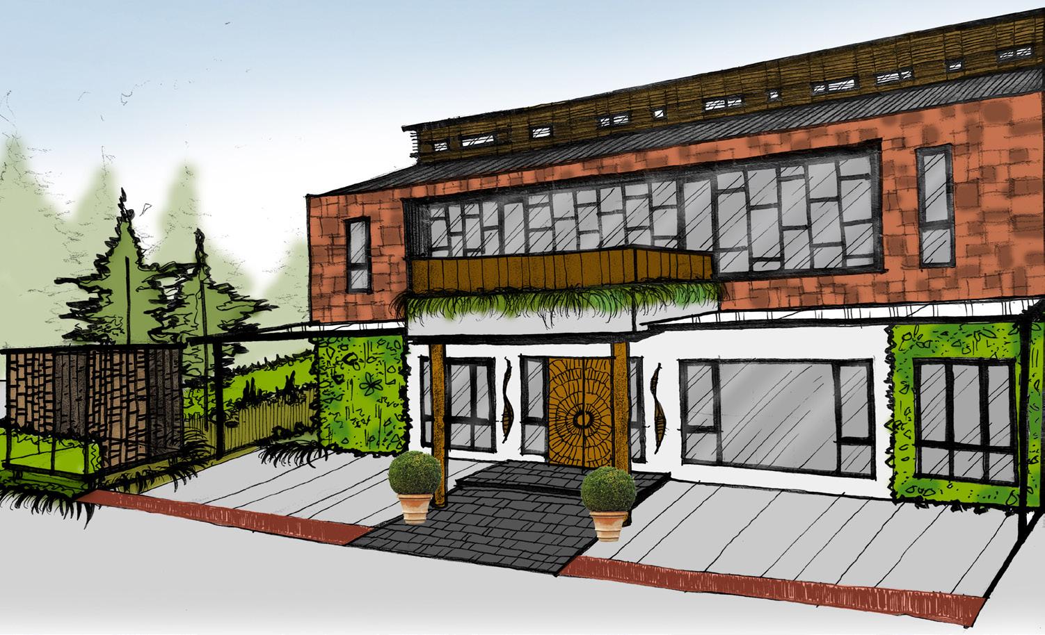
Facade Material Concept


ARCHITECTURE PORTFOLIO 5
EXTERIOR FACADE PROCESS WORK INTERIOR PROCESS WORK


6 TIFFANY ANGEL FANG


ARCHITECTURE PORTFOLIO 7
Stolen Futures, as a studio, aims to look into post-war buildings, one of them is the Sunderland Civic Centre and how it could be repurposed and adaptively reused to promote a programme of community wealth. Our project proposal will re-imagine societies of caring communities where efforts will go into maintaining, adapting, and recycling spaces for the present community needs, as well as revitalizing it, designing it with the provision of subsequent adaptivity to serve the needs of future generations.
The design for this proposal is conceived to provide a new home for the retired and senior citizens of Sunderland, while also embracing the intersection

of various systems, demographics, programs and activities. The building simply manifests the complex nature and needs of the size into a built form, resulting in the current design you see right now. With the studio’s manifesto as our guide, this design will adaptively reuse the existing building, while also adding new components. The mixed-used programme blurs the line between privacy and public, encouraging its own residents to be engage in the community than ever before. The second floor holds various programme of activities that are made for both the residents of the housing and of Sunderland itself, whereas the third and fourth floor provided a communal living space that
employs the double aspect design, allowing views both into the interior of the building and to the outside, with central area and street views at either end. While Sunderland wasn’t short of green parks, the Civic Centre might benefit from extra vegetation to make the area more vibrant and alive. Moreover, interaction with urban vegetation has been linked to a variety of beneficial health impacts and could improve the quality of life. The idea that access to nature can aid healing, or help prevent ailments, will be incorporated into my design proposal.
02 SENIOR HOUSING
TIFFANY ANGEL FANG


PLAN
CENTRE SITE FLOOR PLAN ARCHITECTURE PORTFOLIO 9
CONCEPT IMAGE URBAN DIAGRAMS SITE
CIVIC
A 2ND FLOOR PLAN 1:200 5 10 15 25 m 0 N 1 2 3 4 5 6 7 8 9 10 11 12 13 14 1. Reception Area 2. Workshop Area 3. Health Centre 4. Changing Rooms 5. Gym 6. Unisex Toilets 7. Staff Rooms 8. Stairs, Lift and Exit 9. Lecture Hall 10. Dining Hall 11. Back of House 12. Main Kitchen 13. Cafeteria 14. Central Area 3RD FLOOR PLAN 1:200 5 10 15 25 m 0 N B B A A 15. Living Area 16. Atrium 17. Terrace 18. Storage 19. Garden 20. Kitchen 15 16 17 20 18 18 20 19 GARDEN STORAGE KITCHEN KITCHEN TERRACE LIVING ROOM B B B A A 4TH FLOOR PLAN 1:200 5 10 15 25 m 0 N
10
FLOOR PLANS
TIFFANY ANGEL FANG
0 N SECTION B-B 1:100 5 10 15 25 m 0 N 1. Central Area 2. Car Park 3. Workshop Area 4. Reception Area 5. Gym 6. Private Flat 7. Living Area 8. Atrium 1 2 3 4 5 6 6 7 7 8 9 9 10 9. Terrace 10. Green Roof
LONG STREET SECTION B-B
5 10 15 25 m
10 15 25 m 0 N 1. Central Area 2. Car Park 3. Dining Hall 4. Lecture Hall 5. Living Area 6. Kitchen 1 3 4 5 5 7 2 6 6 8 7. Green Roof 8. Garden
LONG STREET SECTION A-A 5
LONG STREET SECTION A - A
ARCHITECTURE PORTFOLIO 11
LONG STREET SECTION B - B
EXPLODED AXONOMETRIC


12 TIFFANY ANGEL FANG
EXTERIOR PERSPECTIVES


ARCHITECTURE PORTFOLIO 13


CONSTRUCTION DETAILS 14 TIFFANY ANGEL FANG


ARCHITECTURE PORTFOLIO 15
INTERIOR PERSPECTIVES
One of the projects that I involved myself in during my Part 1 experience, is the 70 Shielfield Terrace. This project involves the creation of a garage and workshop building within the redline boundary of 70 Shielfield, where the building take into account pre application advice. The project architect and I work together in a design team to prepare for building warrant application. I involved myself in site surveys, where we measure and record data on site. Several photographs of the site are also taken to help us understand the existing building. Not only that I’ve also involved myself in preparing for the orthographic drawings as well as constructional details to be submitted for Building Control. In this design process, I’ve acted as a participant from Stage 1 to Stage 4 of the RIBA Plan of Work, assisted by the project manager and a structural engineer.


03 70 SHIELDFIELD TERRACE
TIFFANY ANGEL FANG


BUILDING CONTROL Location Plan TD15 Berwick2EEUpon Tweed 70 Sheilfield Terrace Jun 2021 1:1250 BL5304(BC)001 - PV Drawing No. Rev Drawn By Date Project & Client BERWICK-UPON-TWEED Revisions 44-48 Hide Hill T 01289 304432 Edwin Thompson is the trading name of Edwin Thompson LLP a Limited Liability Partnership registered in England & Wales No OC306442. Registered Office: 28 St. Johns Street Keswick Cumbria CA12 5AF DO NOT SCALE All dimensions to be checked on site by the Contractor and any discrepancies reported to the Surveyor. 0 62.5m 25m SCALE 1:1250 50m 12.5m 37.5m 62.5m N Tweedbank Retail Park Northumberland Road SheilfieldTerrace Sports Centre Dean Drive PriorRoad Cornhill Road Sheilfield Park Old Sheilfield EastCoastMainLine IvinsonRoad Greenwood Building Location: ARCHITECTURE PORTFOLIO 17
Old Sheilfield football pitch
TIFFANY
All dimensions to be checked on site by the Contractor and any discrepancies reported to the Surveyor.

Old Sheilfield football pitch
Existing
Existing timber fence to parking area perimeter
gutters within Zinc roofing system
Concealed gutters within Zinc roofing system
Rooflight
Demolished concrete block/render garage previously installed with profile metal roof
Rooflight system within zinc standing seam, zinc colour to be dark grey
Dark Grey Zinc Standing Seam cladding system to roof and walls
Minimum
Existing timber carport with profiled metal roof Gate through stone wall to main property
Existing timber carport with profiled metal roof Gate through stone wall to main property
Existing Dog Kennels
Dog Kennels
Minimum 600mm access route between new and existing walls
Existing & Proposed Site Plans
BUILDING CONTROL
TD15 Berwick2EEUpon Tweed 70 Sheilfield Terrace Jun 2021 A2 1:200
Drawing No. Rev Drawn By Scale Sheet size Date Project & Client BERWICK-UPON-TWEED Revisions also at CARLISLE,
44-48 Hide
TD15
T
F
W
Edwin Thompson is the trading name of Edwin Thompson LLP a Limited Liability Partnership registered in England & Wales No OC306442. Registered Office: 28 St. Johns Street Keswick Cumbria CA12 5AF DO NOT SCALE
BL5304(BC)002 - PV
GALASHIELS, KESWICK, WINDERMERE & NEWCASTLE
Hill Berwick-Upon-Tweed Northumberland
1AB
01289 304432
01289 302027 E berwick@edwin-thompson.co.uk
edwin-thompson.co.uk
N 0 10m 4 SCALE 1:200 8 2 6 10 Existing Site Plan @ 1:200 Proposed Site Plan @ 1:200
Grass Area Grass Area Parking Area Neighbouring Garden 70 Shielfield Terrace Neighbouring Garden Access road
Parking Area Neighbouring Garden 70 Shielfield Terrace Neighbouring Garden Access road
BUILDING CONTROL Existing & Proposed Site Plans TD15 Berwick2EEUpon Tweed 70 Sheilfield Terrace Jun 2021 A2 1:200 BL5304(BC)002 - PV Drawing No. Rev Drawn By Scale Sheet size Date Project & Client BERWICK-UPON-TWEED Revisions also at CARLISLE, GALASHIELS, KESWICK, WINDERMERE & NEWCASTLE 44-48 Hide Hill Berwick-Upon-Tweed Northumberland TD15 1AB T 01289 304432 F 01289 302027 E berwick@edwin-thompson.co.uk W edwin-thompson.co.uk Edwin Thompson is the trading name of Edwin Thompson LLP a Limited Liability Partnership registered in England & Wales No OC306442. Registered Office: 28 St. Johns Street Keswick Cumbria CA12 5AF DO NOT SCALE
N 10m 4 SCALE 1:200 8 6 10 Existing Site Plan @ 1:200 Proposed Site Plan @ 1:200 Old Sheilfield football pitch Old Sheilfield football pitch Grass Area Grass Area Parking Area Neighbouring Garden 70 Shielfield Terrace Neighbouring Garden Access road Existing
All dimensions to be checked on site by the Contractor and any discrepancies reported to the Surveyor.
Parking Area Neighbouring Garden 70 Shielfield Terrace Neighbouring Garden Access road Concealed
EXISTING SITE PLAN PROPOSED SITE PLAN 18
Demolished concrete block/render garage previously installed with profile metal roof ANGEL
timber fence to parking area perimeter
system within zinc standing seam, zinc colour to be dark grey Dark Grey Zinc Standing Seam cladding system to roof and walls
600mm access route between new and existing walls
FANG
EXISTING PLAN
ARCHITECTURE PORTFOLIO
EXISTING ELEVATION
Moisture resistant plasterboard bathrooms, en-suites, WCs and behind Pipe boxes to be constructed around thick plasterboard on 45 x 45mm plywood access panel at hand hole
6 CONCRETE SLAB FLOOR CONSTRUCTION 50mm sand/cement screed, 150mm RC32/40 in-situ concrete 150mm Celotex XR4000 (or equal 1200 gauge Visqueen DPM to 50mm sand blinding, on 150mm well compacted hardcore U-value of 0.13 W/m²K. Perimeter to Area ratio 0.86.
7 ROOF CONSTRUCTION
7.1 GENERAL
Structural timber to be to BS 5268-2: All roof rafters and infill rafters to on loadings in accordance with BS
7.2 SLOPING CEILING
EXTERNAL
Proposed
Proposed
Fibreglass GRP standing seam 9mm OSB board nailed @ 150mm Roofing membrane with 50mm wide cavity with 120mm rigid insulation between 50m rigid insulation under Protect VC foil vapour control 38mm 38mm ceiling branders
12.5mm taper edge plasterboard, 3mm plaster skim.
U-value of 0.13 W/m²K.
8 LEADWORK All flashings, etc, to be Code 4 lead Association's written recommendations.
9 ROOFLIGHTS Rooflights indicated on drawings Velux of low vulnerability classification, complete manufacturer's installation guide. ensure that a watertight seal is achieved U-value of 1.3 W/m²K.
10 WINDOWS
10.1 GENERAL All windows to be upvc to match minimum clear air as noted below. to be fitted with locks. All accessible
Design'.
Trickle ventilation:
General rooms: 12,000mm²
Utility room: 10,000mm²
En-suite & bathroom: 10,000mm² or an average 11,000mm² per apartment.
clear toughened
daylight to be provided
of 1/15th of the respective
below 800mm from FFL
All glass to be to BS
to have exposed
PROPOSED PLANS & ELEVATIONS
BUILDING CONTROL Existing Plan & Elevation TD15 Berwick2EEUpon Tweed 70 Sheilfield Terrace Jun 2021 A2 1:50 BL5304(BC)003 - PV Drawing No. Rev Drawn By Scale Sheet size Date Project & Client BERWICK-UPON-TWEED Revisions also at CARLISLE, GALASHIELS, KESWICK, WINDERMERE & NEWCASTLE 44-48 Hide Hill Berwick-Upon-Tweed Northumberland TD15 1AB 01289 304432 F 01289 302027 E berwick@edwin-thompson.co.uk W edwin-thompson.co.uk Edwin Thompson the trading name of Edwin Thompson LLP Limited Liability Partnership registered in England Wales No OC306442. Registered Office: 28 St. Johns Street Keswick Cumbria CA12 5AF DO NOT SCALE All dimensions to be checked on site by the Contractor and any discrepancies reported to the Surveyor. 0 2.5m 1m SCALE 1:50 2m 500mm 1.5m 2.5m Existing building roof plans @ 1:50 Existing Dog Kennels Stone garden Wall Dog Cage Profiled Metal Roof on timber framed car port Existing garden gate within stone wall Void between concrete garage structure and stone wall - tapers Concrete pad in position of now demolished garage Timber fence to boundary Masonry wall primarily brick with stone elements Timber fence to boundary Timber cladding to carport gable Masonry wall - Brickwork and stone Neighbours Garden 70 Shielfield BUILDING CONTROL Existing Plan & Elevation TD15 Berwick2EEUpon Tweed 70 Sheilfield Terrace Jun 2021 A2 1:50 BL5304(BC)003 - PV Drawing No. Rev Drawn By Scale Sheet size Date Project & Client BERWICK-UPON-TWEED Revisions also at CARLISLE, GALASHIELS, KESWICK, WINDERMERE & NEWCASTLE 44-48 Hide Hill Berwick-Upon-Tweed Northumberland TD15 1AB 01289 304432 F 01289 302027 E berwick@edwin-thompson.co.uk W edwin-thompson.co.uk Edwin Thompson the trading name of Edwin Thompson LLP Limited Liability Partnership registered in England Wales No OC306442. Registered Office: 28 St. Johns Street Keswick Cumbria CA12 5AF DO NOT SCALE All dimensions to be checked on site by the Contractor and any discrepancies reported to the Surveyor. 0 2.5m 1m SCALE 1:50 2m 500mm 1.5m 2.5m Existing building roof plans @ 1:50 Existing Dog Kennels Stone garden Wall Dog Cage Profiled Metal Roof on timber framed car port Existing garden gate within stone wall Void between concrete garage structure and stone wall - tapers Concrete pad in position of now demolished garage Timber fence to boundary Masonry wall primarily brick with stone elements Timber fence to boundary Timber cladding to carport gable Masonry wall - Brickwork and stone Neighbours Garden 70 Shielfield W1 W2 D1 D2 Co D2 W1 W2 D1 Proposed Ground Floor Plan @ 1:100 Proposed Roof Plan @ 1:100 Garage Workshop 5877 8541 6400 9980 9980 6400 Existing Stone Garden Wall Glazed Screen and door assembly Brick landing to external stair Aluminium window frames Rooflights above Timber frame zinc standing seam wall construction Parking area in garage Aluminium window frames Electric roller shutter door to allow vehicle access Existing Stone Garden Wall Dark grey ridge folded zinc system Concealed zinc profiled gutter Rooflight Rooflight Garden Fence Existing Existing Garden Ground Existing Garden Ground Brick landing to external stair 2595 1600 1600 1100 3105,3 1398 780 780 780 Proposed South Elevation @ 1:100 Proposed West Elevation @ 1:100 Proposed North Elevation @ 1:100 Proposed East Elevation @ 1:100 Dark grey facings to perimeter projection Siberian larch or similar Glazed window with RAL 7016 frame Door with RAL 7016 frame Brick base coursing Brick base coursing Standing seam cladding Concealed gutter 9980 6400 2836 Dark grey facings to perimeter projection 3602 562 2826 618 2834 1500 2700 3753 2534 1600 700 700 1600 700 700 1300 1300 2300 938 2100 2000 1600 Electric roller shutter door Dark grey chamfered facings to perimeter projection Siberian larch or similar Brick base coursing Zinc capping to match roof Zinc standing seam system Concealed gutter Eaves Line Standing seam cladding PPC aluminium flashing Brick base coursing 4164 GENERAL NOTES & SPECIFICATION COPYRIGHT © All rights reserved. This document, design and drawing are the sole property of Edwin Thompson LLP. They should be used only for the purposes intended in their original issue and should not be altered, copied, displayed or reproduced in whole or in part without written permission. This document should be read in conjunction with the submitted drawings prepared by Edwin Thompson LLP. All dimensions should be checked on site. All dimensions in millimetres (mm) unless stated otherwise. Do not scale off the drawings. Any drawing errors or divergences should be brought to the attention of the originator of this drawing. All drawings to be read in conjunction with Engineer's drawings. Engineer's drawings supersede architectural drawings. All construction to comply with Building Regulations and British Standards. 1.1 PROPOSED BUILDING CLASS Both the front main house and the rear flat are C3 Dwellinghouses. 1.2 GENERAL 2 FOUNDATIONS 2.1 GENERAL Area of new works to be cleared of topsoil and vegetable matter. Any made ground is to be removed over the plan area of the dwelling house. Should any localised soft spots or voids be found below the proposed formation level these shall be excavated and filled using Type granular sub-base material to Clause 803 of the Specification for Highway Works. Any tree stumps and/or substantial tree roots to be grubbed out and any voids left below the proposed formation level shall be filled using Type 1 granular sub-base material to Clause 803 of the Specification for Highway Works. Any existing field/rubble drains encountered during foundation excavations to be intercepted and diverted. Any old rubble drains, if encountered at formation level, to be excavated and backfilled with Type granular sub-base material to Clause 803 of the Specification for Highway Works. All granular sub-base material to be laid and compacted in layers not exceeding 110mm to Clause 802 of this Specification, without drying out or segregation. 4 EXTERNAL WALLS ABOVE DPC LEVEL 4.1 GENERAL All structural work to comply with Approved Document A of the Building Regulations 2010. All vapour control membranes within timber frame constructions to be overlapped and sealed to prevent, reasonably practicable, any air infiltration into the building. All cavities to be closed with 50mm Rockwool TCB Cavity Barriers (or equal approved) suitable for 12-hour protection: • Horizontally within cavity at ceiling levels Vertically within cavity at all external corners At head of construction 5 INTERNAL PARTITIONS 89 x 38mm (C16) SW timber studs bearing partitions with 12.5mm taper mass per unit area of 10kg/m², joints 100mm Knauf Earthwool Loftroll partitions with minimum density sound insulation level of 43Rw.
Double
4/16/4
U-value
Natural
All
6262:2005 All upvc
W1 W2 D1 D2 Co S D2 W1 W2 D1
glazed
of 1.4 W/m²K.
windows
glass
Kitemarked.
window sills
Ground Floor Plan @ 1:100
Roof Plan
Garage Workshop 5877 8541 6400 9980 9980 6400 Existing Stone Garden Wall Glazed Screen and door assembly Brick landing to external stair Aluminium window frames Rooflights above Timber frame zinc standing seam wall construction Parking area in garage Aluminium window frames Electric roller shutter door to allow vehicle access Existing Stone Garden Wall Dark grey ridge folded zinc system Concealed zinc profiled gutter Rooflight Rooflight Garden Fence Existing Existing Garden Ground Existing Garden Ground Brick landing to external stair 2595 1600 1600 1100 3105,3 1398 780 780 780
South Elevation @ 1:100
West Elevation @
Proposed North Elevation @ 1:100 Proposed East Elevation @ 1:100 Dark grey facings to perimeter projection Siberian larch or similar Glazed window with RAL 7016 frame Door with RAL 7016 frame Brick base coursing Brick base coursing Standing seam cladding Concealed gutter 9980 6400 2836 Dark grey facings to perimeter projection 3602 562 2826 618 2834 1500 2700 3753 2534 1600 700 700 1600 700 700 1300 1300 2300 938 2100 2000 1600 Electric roller shutter door Dark grey chamfered facings to perimeter projection Siberian larch or similar Brick base coursing Zinc capping to match roof Zinc standing seam system Concealed gutter Eaves Line Standing seam cladding PPC aluminium flashing Brick base coursing 4164 GENERAL NOTES & SPECIFICATION COPYRIGHT © All rights reserved. This document, design and drawing are the sole property of Edwin Thompson LLP. They should be used only for the purposes intended in their original issue and should not be altered, copied, displayed or reproduced in whole or in part without written permission. This document should be read in conjunction with the submitted drawings prepared by Edwin Thompson LLP. All dimensions should be checked on site. All dimensions in millimetres (mm) unless stated otherwise. Do not scale off the drawings. Any drawing errors or divergences should be brought to the attention of the originator of this drawing. All drawings to be read in conjunction with Engineer's drawings. Engineer's drawings supersede architectural drawings. All construction to comply with Building Regulations and British Standards. 1.1 PROPOSED BUILDING CLASS Both the front main house and the rear flat are C3 Dwellinghouses. 1.2 GENERAL 2 FOUNDATIONS 2.1 GENERAL Area of new works to be cleared of topsoil and vegetable matter. Any made ground is to be removed over the plan area of the dwelling house. Should any localised soft spots or voids be found below the proposed formation level these shall be excavated and filled using Type granular sub-base material to Clause 803 of the Specification for Highway Works. Any tree stumps and/or substantial tree roots to be grubbed out and any voids left below the proposed formation level shall be filled using Type granular sub-base material to Clause 803 of the Specification for Highway Works. Any existing field/rubble drains encountered during foundation excavations to be intercepted and diverted. Any old rubble drains, if encountered at formation level, to be excavated and backfilled with Type granular sub-base material to Clause 803 of the Specification for Highway Works. All granular sub-base material to be laid and compacted in layers not exceeding 110mm to Clause 802 of this Specification, without drying out or segregation. 4 EXTERNAL WALLS ABOVE DPC LEVEL 4.1 GENERAL All structural work to comply with Approved Document A of the Building Regulations 2010. All vapour control membranes within timber frame constructions to be overlapped and reasonably practicable, any air infiltration into the building. All cavities to be closed with 50mm Rockwool TCB Cavity Barriers (or equal approved) protection: Horizontally within cavity at ceiling levels Vertically within cavity at all external corners At head of construction At 10m horizontal centres around building 5 INTERNAL PARTITIONS 89 x 38mm (C16) bearing partitions mass per unit 100mm Knauf partitions with sound insulation Moisture resistant bathrooms, en-suites, Pipe boxes to thick plasterboard plywood access 6 CONCRETE • 50mm sand/cement • 150mm RC32/40 150mm Celotex 1200 gauge 50mm sand 150mm well U-value of 0.13 Perimeter to 7 ROOF CONSTRUCTION 7.1 GENERAL Structural timber All roof rafters on loadings in 7.2 SLOPING EXTERNAL Fibreglass 9mm OSB Roofing • 50mm 120mm • 50m rigid • Protect 38mm 12.5mm 3mm plaster U-value of 0.13 8 LEADWORK All flashings, etc, Association's written 9 ROOFLIGHTS Rooflights indicated of low vulnerability manufacturer's ensure that a watertight U-value of 1.3 W/m²K. 10 WINDOWS 10.1 GENERAL All windows to minimum clear to be fitted with Design'. Trickle ventilation: General rooms: Utility room: En-suite & or an average apartment. Double glazed U-value of 1.4 W/m²K. Natural daylight windows of 1/15th All glass below Kitemarked. All All upvc window
@ 1:100
Proposed
Proposed
1:100
19

CONSTRUCTION DETAILS 20 TIFFANY ANGEL FANG
LIGHTING & SWITCHES Kitchens to have minimum 6 No. socket outlets. Apartments to have
The fittings may be either: dedicated fittings which will have a separate control gear and will only take fluorescent lamps (pin-based lamps); or • fittings including lamps with integrated control gear (bayonet or Edison screw base lamps).
Outlets and controls of electrical fixtures and systems to be positioned at least 350mm from any internal corner, projecting wall or similar obstruction and not more than 1.2m above floor level. This includes fixtures such as sockets, switches, fire alarm call points and timer controls or programmers.
Within this height range: light switches should be positioned at a height of between 900mm and 1.1m above floor level. standard switched or unswitched socket outlets and outlets for other services such as telephone or television should be positioned at least 450mm above floor level. Above an obstruction, such as a worktop, fixtures should be at least 150mm above the projecting surface. Where socket outlets are concealed, such as to the rear of white goods in a kitchen, separate switching should be provided in an accessible position, to allow appliances o be isolated.
12.1.3 CARBON MONOXIDE DETECTION
Carbon monoxide detectors should comply with BS EN 50291-1:2010 and be powered by a battery designed to operate for the working life of the detector. The detector should incorporate a warning device to alert the users when its working life is due to expire. Hard wired mains operated carbon monoxide detectors complying with BS EN 50291-1:2010 (Type A) with fixed wiring (not plug in types) may be used as an alternative, provided they are fitted with a sensor failure warning device. Where carbon monoxide detectors are within the scope of either or both:
European Directive 2006/95/EC Low Voltage Directive, and/or
• European Directive 1999/5/EC Radio and Telecommunication Terminal Equipment Directive, they should be constructed to fully comply with all applicable safety aspects of the Directive(s).
The guidance in this clause takes account of the audibility levels in adjoining rooms and the effect of carbon monoxide moving throughout the building. Carbon monoxide detectors should include an integral sounder.
A carbon monoxide detection system to alert occupants to the presence of carbon monoxide should consist of at least:
1 carbon monoxide detector in every space containing a fixed combustion appliance (excluding an appliance used solely for cooking) and, 1 carbon monoxide detector to provide early warning to high risk accommodation, that is, a bedroom or principal habitable room, where a flue passes through these rooms.
Unless otherwise indicated by the manufacturer, carbon monoxide detectors should be either:
ceiling mounted and positioned at least 300mm from any wall or
• wall mounted and positioned at least 150mm below the ceiling and higher than any door or window in the room.
Carbon monoxide detectors in the space containing the combustion appliance should be sited between 1m and 3m from the appliance
Note: Where the combustion appliance is located in a small space it may not be possible to locate the detector within that space.
In such circumstances the detector may be located at the appropriate distance outwith the space.
A carbon monoxide detector should not be sited: in an enclosed space (for example in a cupboard or behind a curtain), where it can be obstructed (for example by furniture),
• directly above a sink, next to a door or window, next to an extract fan,
• next to an air vent or similar ventilation opening, in an area where the temperature may drop below -10°C or exceed 40°C, unless it is designed to do so, where dirt and dust may block the sensor,
1 gang light dimmer switch
Double switched socket
Single switched fuse spur above worktop level
8 gang module grid switch
1 gang light switch
2 gang light switch
1 gang/2 way light switch
2 gang/2 way light switch
backfilled until pea
Old Sheilfield Grass Area Parking
Wifi
Notes:
Electrical installation should be designed, constructed, installed and tested such that it is in accordance with the recommendations of BS 7671:2008.
FGL
*Smoke and heat detectors to be mains operated optical type with battery back up to be interlinked.
** Carbon monoxide detectors should comply with BS EN 50291-1:2010 and be powered by a battery designed to operate for the working life of the detector. Unless otherwise indicated by the manufacturer, carbon monoxide detectors should be either: Ceiling mounted and positioned at least 300mm from any wall, or wall mounted and positioned at least 150mm below the ceiling and higher than any door or window in the room
1:10 100 150
Pea
DRAINAGE DETAIL
•
SERVICING LAYOUT
•
Electrical schedule Double socket with USB interface Single switched wall socket
1200
Double switched wall socket Single switched wall socket
above floor level
1200mm
above floor level
1200
above floor level shaver socket
2 gang light dimmer switch pull switch emergency pull switch light point pendant light point bayonet light point LED Strip wall light
Router Downlighter Mechanical extract fan door bell push Door bell chime smoke detector heat detector carbon monoxide detector thermostat central water heating programmer security alarm consumer unit electric shower BT incoming telephone point telephone jack outlet tv aerial point tv amplifier point mechanical extract fan outlet immersion heater and thermostat inbuilt hdmi cable 2 2 2 2 E s h co p s/a c/u e/s mef hdmi 2 emergency lighting e Wifi Repeater carbon dioxide detector co2 light point - fluorescent tube external light balanced flue position bf 2 2 2 2 2 2 2 2 2 2 2 2 2 2 2 2 2 2 2 2 2 2 s co RWP RWP BUILDING CONTROL Servicing Layout TD15 Berwick2EEUpon Tweed 70 Shielfield Terrace Dec 2022 A3 1:50 BL5304(BC)006 A TAF Edwin Thompson is the trading name of Edwin Thompson LLP a Limited Liability Partnership registered in England & Wales No OC306442. Registered Office: 28 St. Johns Street Keswick Cumbria CA12 5AF DO NOT SCALE All dimensions to be checked on site by the Contractor and any discrepancies reported to the Surveyor. Drawing No. Rev Drawn By Scale Sheet size Date Project & Client. Revisions BERWICK-UPON-TWEED also at CARLISLE, GALASHIELS, KESWICK, WINDERMERE & NEWCASTLE 44-48 Hide Hill Berwick-Upon-Tweed Northumberland TD15 1AB 01289 304432 F 01289 302027 E berwick@edwin-thompson.co.uk W edwin-thompson.co.uk Servicing Layout - Ground Floor 1:50 0 2.5m 1m SCALE 1:50 2m 500mm 1.5m 2.5m Rainwater pipe to have hand access panel at base Rainwater pipe to have hand access panel at base 12 ELECTRICAL WORKS 12.1 GENERAL All electrical works to comply with the latest IEE regulations and Approved Document P of the Building Regulations 2010 and to be designed, constructed, installed and tested such that it is in accordance with the recommendations of BS 7671: 2009, as amended. 12.1.1 FIRE DETECTION Fire detection and alarm system designed and installed in accordance with BS 5839: Part 6: 2004, to be fitted within 7m of a door to a living room or kitchen and within 3m of a door to a bedroom. The fire detection and alarm system to be interlinked. Alarms in all circulation spaces that form part of escape routes and rooms or areas that present a high fire risk. Heat detectors to be provided to all kitchens at maximum 5.3m from any potential source of fire. Detectors are to be connected to a mains circuit independent from any other equipment other than lighting and are to be fitted 300mm minimum from any wall or light fitting. System to have battery backup. In areas with sloping or peaked ceilings install the smoke alarm 900mm from the highest point measured horizontally, because "dead" air at the apex may prevent smoke reaching the unit. 12.1.2 SOCKET OUTLETS,
minimum 4 No. socket outlets. En-suite light fittings to be ow voltage/shrouded. Shower isolation
to
outside bath/shower rooms. In a bathroom or shower room, an electric shaver power outlet, complying with BS EN 61558-2-23:2001
be
Carbon monoxide dectectors in the space containing the combustion appliance should be sited between 1m and 3m from the appliance. connecting portable equipment.
switches
be
may
installed. Other than this, there should be no socket outlets and no means for
The junctions of all boxings for services and the building fabric to be sealed to prevent the infiltration of air into the building. All recessed downlighter & spotlights to ground floor to have hoods to maintain the fire resistance of the floor. A minimum of 75% of the fixed light fittings and lamps installed in a dwelling should be low energy type.
• in a damp or humid location, or in the immediate vicinity of a cooking appliance. Additional guidance on the siting of carbon monoxide detectors, including enhanced coverage, can be found in BS EN 50292:2002.
Cross-section of Drainage
Pea Gravel Selected backfill material compacted in max. layers, 150mm.
fall drain to be
gravel. Min 100mm above pipe crown Existing Plant RE Trap Gully BITG BITG Proposed Drainage Detail @ 1:50 0 2.5m 1m SCALE 1:50 2m 500mm 1.5m 2.5m 0 500mm 200mm SCALE 1:10 400mm 100mm 300mm 500mm Min 1:100 fall UPVC 100mm in diameter. Old Sheilfield Grass Area Parking
100mm diameter UPVC drain laid to minimum 1:100
1:10 100 150
Gravel Selected backfill material compacted in max. layers, 150mm. FGL 100mm diameter UPVC drain laid to minimum 1:100 fall drain to be backfilled until pea gravel. Min 100mm above pipe crown Existing Plant RE Trap Gully BITG BITG Proposed Drainage Detail @ 1:50 0 2.5m 1m SCALE 1:50 2m 500mm 1.5m 2.5m 0 500mm 200mm SCALE 1:10 400mm 100mm 300mm 500mm Min 1:100 fall UPVC 100mm in diameter.
Cross-section of Drainage
21
ARCHITECTURE PORTFOLIO
Another project that I did for my Part 1 Experience is the St Andrews Road. The brief being to obtain planning permission and submit building regulations to allow for the creation of a new wrap around extension at the existing property, where the extension to include kitchen/dining area and a possible bedroom. Discussion with client about the works of this nature exceeding her budget of £50k pose as a problem in the beginning, but after careful consideration, client decided to use labour from her family to reach her ideal budget. The professional services that I did along with a project architect, trainee architectural technician and a structural engineer falls on the RIBA Plan of Work, from Stage 1 to Stage 5. Most of my hours as a participant falls on Stage 3 and Stage 4 of the RIBA Plan of Work where I prepare and draft drawings for both Planning and Building Control submissions. The rest of my hours as an observer falls on Stage 1 and Stage 2 of the RIBA Plan of Work.


04 ST ANDREWS ROAD
TIFFANY ANGEL FANG
ST.GEORGE'SROAD
Northings: 654352
MAGDALENEDRIVE
A1167NORTHROAD
MAGDALENEDRIVE
A1167NORTHROAD BEDEAVENUE


Red line boundary: 214.5m2

ST. ANDREW'S ROAD
ST.GEORGE'SROAD ST. CUTHBERT'S ROAD
Drawing No. Rev Drawn By Scale Sheet size Date also at CARLISLE, GALASHIELS, KESWICK, WINDERMERE & NEWCASTLE BUILDING CONTROL 08-12-22 A4 1:1250 BS5430(BC)-001 - TF Location Plan N
ST. ANDREW'S ROAD
2 Location Plan 1:1250 0 62.5m 25m SCALE 1:1250 50m 12.5m 37.5m 62.5m North to A1
to Berwickupon-Tweed ARCHITECTURE PORTFOLIO 23
South
EXISTING SITE PLAN
EXISTING FLOOR PLANS
EXISTING ELEVATIONS
ST. ANDREW'S
ANDREW'S
Edwin Thompson the trading name Edwin Thompson LLP Limited Liability Partnership registered in England Wales OC306442. Registered Office: 28 St. Johns Street Keswick Cumbria CA12 5AF DO NOT SCALE All dimensions to be checked on site by the Contractor and any discrepancies reported to the Surveyor. Drawing No. Rev Drawn By Scale Sheet size Date Project Client. BERWICK-UPON-TWEED also at CARLISLE, GALASHIELS, KESWICK, WINDERMERE NEWCASTLE 44-48 Hide Hill Berwick-Upon-Tweed Northumberland TD15 1AB 01289 304432 01289 302027 berwick@edwin-thompson.co.uk edwin-thompson.co.uk Proposed Site Plan 1:500 Northings: 654352 Eastings: 399414 BUILDING CONTROL TD15 1QF Northumberland Berwick-upon-Tweed 4 St. Andrew's Road 08-12-22 A3 1:500 BS5430(BC)-002 - TF Existing & Proposed Site Plans Red line boundary: 214.5m2 Building footprint: 74.8m N Existing Site Plan 1:500 25m 10 SCALE 1:500 20 5 15 25 Red line boundary: 214.5m Building footprint: 38.6m N 0 25m 10 SCALE 1:500 20 15 25 ST. ANDREW'S ROAD Edwin Thompson the trading name of Edwin Thompson LLP Limited Liability Partnership registered England Wales No OC306442. Registered Office: 28 St. Johns Street Keswick Cumbria CA12 5AF DO NOT SCALE All dimensions to be checked on site by the Contractor and any discrepancies reported to the Surveyor. Drawing No. Rev Drawn By Scale Sheet size Date Project Client. BERWICK-UPON-TWEED also CARLISLE, GALASHIELS, KESWICK, WINDERMERE & NEWCASTLE 44-48 Hide Hill Berwick-Upon-Tweed Northumberland TD15 1AB 01289 304432 01289 302027 berwick@edwin-thompson.co.uk edwin-thompson.co.uk Proposed Site Plan 1:500 Northings: 654352 Eastings: 399414 BUILDING CONTROL TD15 1QF Northumberland Berwick-upon-Tweed 4 St. Andrew's Road 08-12-22 A3 1:500 BS5430(BC)-002 - TF Existing & Proposed Site Plans Red line boundary: 214.5m2 Building footprint: 74.8m 25m N 0 25m 10 SCALE 1:500 20 5 15 25 BUILDING CONTROL TD15 1QF Northumberland Berwick-upon-Tweed 4 St. Andrew's Road 08-12-22 A2 As BS5430(BC)-005 - TF Demolitions Drawing No. Rev Drawn By Scale Sheet size Date Project & Client BERWICK-UPON-TWEED Revisions also at CARLISLE, GALASHIELS, KESWICK, WINDERMERE 44-48 Hide Hill Berwick-Upon-Tweed Northumberland TD15 1AB T 01289 304432 01289 302027 E berwick@edwin-thompson.co.uk W edwin-thompson.co.uk DO NOT SCALE All dimensions to be checked on site by any discrepancies reported to the Surveyor. Bathroom Bedroom #1 Bedroom #2 Ground Floor Plan 1:50 Boundary First Floor Plan 1:50 Roof Plan 1:100 Living Storage Kitchen West Elevation 1:100 Boundary Boundary Ground level +0mm First Floor +2833mm Ridge +7213mm Ridge +3088mm Eaves +5213mm Eaves +2447mm South Elevation 1:100 East Elevation 1:100 Ground level +0mm First Floor +2833mm Ridge +7213mm Ridge +3088mm Eaves +5213mm Eaves +2447mm 0 5m 2 SCALE 1:100 4 1 5 0 2.5m 1m SCALE 1:50 2m 500mm 1.5m 2.5m Areas blocked Legend Areas demolished BUILDING CONTROL TD15 1QF Northumberland Berwick-upon-Tweed 4 St. Andrew's Road 08-12-22 A2 As Shown BS5430(BC)-005 - TF Demolitions Drawing No. Rev Drawn By Scale Sheet size Date Project & Client BERWICK-UPON-TWEED Revisions also at CARLISLE, GALASHIELS, KESWICK, WINDERMERE & NEWCASTLE 44-48 Hide Hill Berwick-Upon-Tweed Northumberland TD15 1AB T 01289 304432 F 01289 302027 E berwick@edwin-thompson.co.uk W edwin-thompson.co.uk Bathroom Bedroom #1 Bedroom #2 First Floor Plan 1:50 Roof Plan 1:100 Living Storage Kitchen Boundary Boundary Ground level +0mm First Floor +2833mm Ridge +7213mm Ridge +3088mm Eaves +5213mm Eaves +2447mm South Elevation 1:100 East Elevation 1:100 Ground level +0mm First Floor +2833mm Ridge +7213mm Ridge +3088mm Eaves +5213mm Eaves +2447mm 5m 2 SCALE 1:100 4 1 3 5 2.5m Areas to be blocked up Legend Areas to be demolished BUILDING CONTROL TD15 1QF Northumberland Berwick-upon-Tweed 4 St. Andrew's Road 08-12-22 A2 As BS5430(BC)-005 - TF Demolitions Drawing No. Rev Drawn By Scale Sheet size Date Project & Client BERWICK-UPON-TWEED Revisions also at CARLISLE, GALASHIELS, KESWICK, WINDERMERE 44-48 Hide Hill Berwick-Upon-Tweed Northumberland TD15 1AB T 01289 304432 01289 302027 E berwick@edwin-thompson.co.uk W edwin-thompson.co.uk DO NOT SCALE All dimensions to be checked on site by any discrepancies reported to the Surveyor. Bathroom Bedroom #1 Bedroom #2 Ground Floor Plan 1:50 Boundary First Floor Plan 1:50 Roof Plan 1:100 Living Storage Kitchen West Elevation 1:100 Boundary Boundary Ground level +0mm First Floor +2833mm Ridge +7213mm Ridge +3088mm Eaves +5213mm Eaves +2447mm South Elevation 1:100 East Elevation 1:100 Ground level +0mm First Floor +2833mm Ridge +7213mm Ridge +3088mm Eaves +5213mm Eaves +2447mm 0 5m 2 SCALE 1:100 4 1 5 0 2.5m 1m SCALE 1:50 2m 500mm 1.5m 2.5m Areas blocked Legend Areas demolished
ROAD ST.
ROAD
24 TIFFANY
PROPOSED SITE PLAN
ANGEL FANG
SLAB FLOOR CONSTRUCTION 8 LEADWORK All flashings, etc, to be Code 4 and fixed in accordance with the Lead Development Association's written recommendations. 9 ROOFLIGHTS Rooflights indicated on drawings Velux GGL MK08 - 1398 780 (or equal approved) of low vulnerability classification, complete with profiled facings to suit roof manufacturer's installation guide. It is the responsibility of the roofing ensure that watertight seal is achieved around the rooflight to prevent water U-value of 1.3 W/m²K. 10 WINDOWS 10.1 GENERAL All windows to be upvc to match existing with permanent ventilators at minimum clear air as noted below. Windows to have opening restrictors fitted. to be fitted with locks. All accessible windows to meet with Section 2 Design'. Trickle ventilation: General rooms: 12,000mm² Utility room: 10,000mm² En-suite & bathroom: 10,000mm² or an average 11,000mm² per room with minimum of 11,000mm² apartment. Double glazed 4/16/4 clear toughened glass Low-E units with soft coat and U-value of 1.4 W/m²K. Natural daylight to be provided to each apartment with a minimum glazed windows of 1/15th of the respective room area. All glass below 800mm from FFL to be laminated 6mm safety glass Kitemarked. All glass to be to BS 6262:2005 and BS 6206:1981. All upvc window sills to have exposed drips. 11 BI-FOLD DOORS 11.1 GENERAL U-value of 1.5 W/m²K for double glazed doors. All concrete and timber door sills to have exposed drips. S
New SVP with Durgo New RWP Obscured glazing RWP
well compacted hardcore New BITG
Upstand to roof verge Upstand to roof verge
sand/cement screed, on 150mm RC32/40 in-situ concrete slab, on 150mm Celotex XR4000 (or equal approved) insulation, on 1200 gauge Visqueen DPM to link with all DPC's in walls, on 50mm sand blinding, on H
INTERNAL PARTITIONS 89 38mm (C16) SW timber studs @ 600mm centres to non-load bearing and load bearing partitions with taper edged plasterboard both sides with minimum mass per unit area of 10kg/m², joints taped and filled, skim coat plaster. 100mm Knauf Earthwool Loftroll 40 (for sound insulation) to be fitted to all partitions with minimum 10kg/m³, to provide a minimum airborne sound insulation level of 43Rw. Moisture resistant plasterboard to be used to internal face of partitions to all bathrooms, en-suites, behind
5 INTERNAL PARTITIONS 89 x 38mm (C16) SW timber studs @ 600mm centres to non-load bearing taper edged plasterboard both sides minimum mass per unit area of skim coat plaster. 100mm Knauf Earthwool Loftroll 40 (for sound insulation) to be fitted to 10kg/m³, to provide minimum airborne sound insulation level of 43Rw. Moisture resistant plasterboard to be used to internal face of partitions behind kitchen units. Pipe boxes to be constructed around new pipework or AAVs, comprising SW timber framing and with screw fixed plywood access panel at hand hole 6 CONCRETE SLAB FLOOR CONSTRUCTION 50mm New SVP Stub stack with durgo
PROPOSED FLOOR PLANS
New RWP New SVP with Durgo
timber studs at 600mm centres infilled with 140mm thick rigid insulation, with 25mm rigid insulation on inner face of studs, with Protect VC foil vapour control layer, with 25mm 50mm timber battens forming service void, with 12.5mm thick taper edged plasterboards taped and filled Finished with 3mm thick plaster skim. Firestops, consisting of 2 No. 25 x 50mm treated SW timber battens with DPC wrapped around, to be fixed: Fully around all new window and external door openings. Timber clad U-value of 0.13W/m²K.
centres infilled with 140mm thick 25mm rigid insulation on inner face of studs, with Protect VC foil vapour control layer, with 25mm x 50mm timber battens forming service void, with 12.5mm thick taper edged plasterboards taped and filled Finished with 3mm thick plaster skim. Firestops, consisting of No. 25 x 50mm treated SW timber battens with DPC Fully around all new window and external door openings. Timber clad U-value of 0.13W/m²K. FW PPIC FW PPIC SW PPIC
at 600mm centres infilled with 140mm thick rigid insulation, with 25mm rigid insulation on inner face of studs, with Protect VC foil vapour control layer, with 25mm 50mm timber battens forming service void, with 12.5mm thick taper edged plasterboards taped and filled Finished with 3mm thick plaster skim. Firestops, consisting of 2 No. 25 x 50mm treated SW timber battens with DPC wrapped around, to be fixed: Fully around all new window and external door openings. Timber clad U-value of 0.13W/m²K.
W D 0 5m 2 SCALE 1:100 4 1 3 5 Bathroom Bedroom #1 Bedroom #2 2112 1868 Ground Floor Plan 1:50 Boundary First Floor Plan 1:50 2389 3364 4627 2882 Living 3199 Storage 3094 4083 Bedroom 1275 1070 2351 1522 En-suite 5684 Kitchen 4551 2133 948 2029 Dining East Elevation 1:100 West Elevation 1:100 South Elevation 1:100 Boundary Ground level +0mm Ridge +3411mm Eaves +2360mm Ridge +3411mm Eaves +2360mm 2351 5065 7765 2700 600 7765 7165 3000 2096 1500 1422 2794 10881 8087 844 941 Ground level +0mm Ridge +3411mm Eaves +2360mm 1400 1422 14 14 13 0 2.5m 1m SCALE 1:50 2m 500mm 1.5m 2.5m 3525 FW PPIC SW PPIC FW/SW, Heavy duty cover. 100 dia. BITG Waste Pipe RWP BITG Existing, to combine public sewer. New SVP with Durgo RWP Timber wall bearer (See scene spec) MK08 (GGL) 1398x780 100mm Deep Flow Gutter 47x175 c24 timber rafters @ 400mm crs 47x175 c24 timber rafters @ 400mm crs Double joist up either side of roof lights RWP BITG 3381 2948 3525 GENERAL NOTES & SPECIFICATION COPYRIGHT © All rights reserved. This document, design and drawing are the sole property of Edwin Thompson LLP. They should be used only for the purposes intended in their original issue and should not be altered, copied, displayed or reproduced in whole or in part without written permission. This document should be read in conjunction with the submitted drawings prepared by Edwin Thompson LLP. All dimensions should be checked on site. All dimensions in millimetres (mm) unless stated otherwise. Do not scale off the drawings. Any drawing errors or divergences should be brought to the attention of the originator of this drawing. All drawings to be read in conjunction with Engineer's drawings. Engineer's drawings supersede architectural drawings. All construction to comply with Building Regulations and British Standards. 1.1 PROPOSED BUILDING CLASS Both the front main house and the rear flat are C3 Dwellinghouses. 1.2 GENERAL All new works are to be in accordance with The Building Regulations 2010 and all current amendments. All new works, products and processes are to be in accordance with the relevant British Standards and FOUNDATIONS 2.1 GENERAL Area of new works to be cleared of topsoil and vegetable matter. Any made ground is to be removed over the plan area of the dwelling house. Should any localised soft voids be found below the proposed formation level these shall be excavated and filled using Type sub-base material to Clause 803 of the Specification for Highway Works. Any tree stumps and/or substantial roots to be grubbed out and any voids left below the proposed formation level shall be filled using Type sub-base material to Clause 803 of the Specification for Highway Works. Any existing field/rubble encountered during foundation excavations to be intercepted and diverted. Any old rubble drains, if encountered formation level, to be excavated and backfilled with Type granular sub-base material to Clause 803 Specification for Highway Works. All granular sub-base material to be laid and compacted in layers not 110mm to Clause 802 of this Specification, without drying out or segregation. Top of foundation toe to be a minimum of 400mm below ground level. Footing excavation depths minimum of 700mm below ground level. Competent person to check formation level prior to concrete poured. Foundations to Engineer's design to be reinforced and to Structural Engineer's recommendations 4 EXTERNAL WALLS ABOVE DPC LEVEL 4.1 GENERAL All structural work to comply with Approved Document A of the Building Regulations 2010. All vapour control membranes within timber frame constructions to be overlapped and sealed to prevent, reasonably practicable, any air infiltration into the building. All cavities to be closed with 50mm Rockwool TCB Cavity Barriers (or equal approved) suitable for protection: Horizontally within cavity at ceiling levels Vertically within cavity at all external corners At head of construction At 10m horizontal centres around building All new external windows, doors and openings to have DPCs applied fully around them. All internal reveals lined with 37.5mm Celotex PL4000 (25mm insulation and 12.5mm plasterboard) (or equal approved) on AVCL VC Foil Ultra vapour control membrane, fully lapped and sealed around external windows, doors and openings. 4.2 EXTERNAL EXTENTION WALL CONSTRUCTION EXTERNAL 10mm thick through colour Parex or KRend render finish (colour to be agreed). On 100mm medium density blocks, with 50mm wide cavity. Protect TF200 Thermo breather membrane, on 9mm thick (Grade 3) OSB board, on 140 38 (C16)
kitchen units. Pipe boxes to be constructed around new pipework or AAVs, comprising 12.5mm thick plasterboard on SW timber framing and with a screw fixed plywood access panel at hand hole level(s). CONCRETE SLAB FLOOR CONSTRUCTION 50mm sand/cement screed, on 150mm RC32/40 in-situ concrete slab, on 150mm Celotex XR4000 (or equal approved) insulation, on 1200 gauge Visqueen DPM to link with all DPC's in walls, on 50mm sand blinding, on 150mm well compacted hardcore U-value of 0.13 W/m²K. Perimeter to Area ratio 0.86. ROOF CONSTRUCTION 7.1 GENERAL Structural timber to be to BS 5268-2: 2002. All roof rafters and infill rafters to be designed and detailed by Structural Engineer based on loadings accordance with BS EN 1995-1-1:2004 A1:2008. 7.2 SLOPING CEILING EXTERNAL Fibreglass GRP standing seam roof, on 9mm OSB board nailed @ 150mm c/cs, on Roofing membrane with 50mm wide cavity with 120mm rigid insulation between 175mm 47mm rafters at 400mm (C24), on 50m rigid insulation under rafters, on Protect VC foil vapour control layer joints taped, on 38mm x 38mm ceiling branders with 12.5mm taper edge plasterboard, and 3mm plaster skim. U-value of 0.13 W/m²K. LEADWORK All flashings, etc, to be Code lead and fixed in accordance with the Lead Development Association's written recommendations. 9 ROOFLIGHTS Rooflights indicated on drawings Velux GGL MK08 - 1398 x 780 (or equal approved) to be of low vulnerability classification, complete with profiled facings to suit roof finish as per manufacturer's installation guide. It is the responsibility of the roofing installer to ensure that a watertight seal is achieved around the rooflight to prevent water ingress. U-value of 1.3 W/m²K. 10 WINDOWS 10.1 GENERAL All windows to be upvc to match existing with permanent ventilators at head to give a minimum clear air as noted below. Windows to have opening restrictors fitted. Windows to be fitted with locks. All accessible windows to meet with Section of 'Secured by Design'. Trickle ventilation: General rooms: 12,000mm² Utility room: 10,000mm² En-suite & bathroom: 10,000mm² or an average 11,000mm² per room with a minimum of 11,000mm² in each apartment. Double glazed 4/16/4 clear toughened glass Low-E units with soft coat and argon filled. U-value of 1.4 W/m²K. Natural daylight to be provided to each apartment with minimum glazed area to windows of 1/15th of the respective room area. All glass below 800mm from FFL to be laminated 6mm safety glass and clearly Kitemarked. All glass to be to BS 6262:2005 and BS 6206:1981. All upvc window sills to have exposed drips. 11 BI-FOLD DOORS 11.1 GENERAL U-value of 1.5 W/m²K for double glazed doors. All concrete and timber door sills to have exposed drips. S H New BITG FW PPIC FW PPIC SW PPIC New SVP Stub stack with durgo Upstand to roof verge Upstand to roof verge New SVP with Durgo New RWP Obscured glazing RWP New RWP New SVP with Durgo W D 0 5m 2 SCALE 1:100 4 1 3 5 Bathroom Bedroom #1 Bedroom #2 2112 1868 Ground Floor Plan 1:50 Boundary First Floor Plan 1:50 2389 3364 4627 2882 Living 3199 Storage 3094 4083 Bedroom 1275 1070 2351 1522 En-suite 5684 Kitchen 4551 2133 948 2029 Dining East Elevation 1:100 West Elevation 1:100 South Elevation 1:100 Boundary Ground level +0mm Ridge +3411mm Eaves +2360mm Ridge +3411mm Eaves +2360mm 2351 5065 7765 2700 600 7765 7165 3000 2096 1500 1422 2794 10881 8087 844 941 Ground level +0mm Ridge +3411mm Eaves +2360mm 1400 1422 14 14 13 0 2.5m 1m SCALE 1:50 2m 500mm 1.5m 2.5m 3525 FW PPIC SW PPIC FW/SW, Heavy duty cover. 100 dia. BITG Waste Pipe RWP BITG Existing, to combine public sewer. New SVP with Durgo RWP Timber wall bearer (See scene spec) MK08 (GGL) 1398x780 100mm Deep Flow Gutter 47x175 c24 timber rafters @ 400mm crs 47x175 c24 timber rafters @ 400mm crs Double joist up either side of roof lights RWP BITG 3381 2948 3525 GENERAL NOTES & SPECIFICATION COPYRIGHT © All rights reserved. This document, design and drawing are the sole property of Edwin Thompson LLP. They should be used only for the purposes intended in their original issue and should not be altered, copied, displayed or reproduced in whole or in part without written permission. This document should be read in conjunction with the submitted drawings prepared by Edwin Thompson LLP. All dimensions should be checked on site. All dimensions in millimetres (mm) unless stated otherwise. Do not scale off the drawings. Any drawing errors or divergences should be brought to the attention of the originator of this drawing. All drawings to be read in conjunction with Engineer's drawings. Engineer's drawings supersede architectural drawings. All construction to comply with Building Regulations and British Standards. 1.1 PROPOSED BUILDING CLASS Both the front main house and the rear flat are C3 Dwellinghouses. FOUNDATIONS 2.1 GENERAL Area of new works to be cleared of topsoil and vegetable matter. Any made ground is to be removed over the plan area of the house. Should any localised soft voids be found below the proposed formation level these shall be excavated and filled using Type sub-base material to Clause 803 of the Specification for Highway Works. Any tree stumps and/or substantial roots to be grubbed out and any voids left below the proposed formation level shall be filled using Type sub-base material to Clause 803 of the Specification for Highway Works. Any existing field/rubble encountered during foundation excavations to be intercepted and diverted. Any old rubble drains, if encountered formation level, to be excavated and backfilled with Type granular sub-base material to Clause 803 Specification for Highway Works. All granular sub-base material to be laid and compacted in layers not 110mm to Clause 802 of this Specification, without drying out or segregation. 4 EXTERNAL WALLS ABOVE DPC LEVEL 4.1 GENERAL All structural work to comply with Approved Document A of the Building Regulations 2010. All vapour control membranes within timber frame constructions to be overlapped and sealed to prevent, reasonably practicable, any air infiltration into the building. All cavities to be closed with 50mm Rockwool TCB Cavity Barriers (or equal approved) suitable for protection: Horizontally within cavity at ceiling levels Vertically within cavity at all external corners At head of construction At 10m horizontal centres around building All new external windows, doors and openings to have DPCs applied fully around them. All internal reveals lined with 37.5mm Celotex PL4000 (25mm insulation and 12.5mm plasterboard) (or equal approved) on AVCL VC Foil Ultra vapour control membrane, fully lapped and sealed around external windows, doors and openings. 4.2 EXTERNAL EXTENTION WALL CONSTRUCTION EXTERNAL 10mm thick through colour Parex or KRend render finish (colour to be agreed). On 100mm medium density blocks, with 50mm wide cavity. Protect TF200 Thermo breather membrane, on 9mm thick (Grade 3) OSB board, on 140 38 (C16) timber studs
CONCRETE
50mm
150mm
U-value of 0.13 W/m²K. Perimeter to Area ratio 0.86. ROOF CONSTRUCTION 7.1 GENERAL Structural timber to be to BS 5268-2: 2002. All roof rafters and infill rafters to be designed and detailed by Structural Engineer based on loadings accordance with BS EN 1995-1-1:2004 A1:2008. 7.2 SLOPING CEILING EXTERNAL Fibreglass GRP standing seam roof, on 9mm OSB board nailed @ 150mm c/cs, on Roofing membrane with 50mm wide cavity with 120mm rigid insulation between 175mm 47mm rafters at 400mm (C24), on 50m rigid insulation under rafters, on Protect VC foil vapour control layer joints taped, on 38mm x 38mm ceiling branders with 12.5mm taper edge plasterboard, and 3mm plaster skim. U-value of 0.13 W/m²K. LEADWORK All flashings, etc, to be Code lead and fixed in accordance with the Lead Development Association's written recommendations. 9 ROOFLIGHTS Rooflights indicated on drawings Velux GGL MK08 - 1398 x 780 (or equal approved) to be of low vulnerability classification, complete with profiled facings to suit roof finish as per manufacturer's installation guide. It is the responsibility of the roofing installer to ensure that a watertight seal is achieved around the rooflight to prevent water ingress. U-value of 1.3 W/m²K. 10 WINDOWS 10.1 GENERAL All windows to be upvc to match existing with permanent ventilators at head to give a minimum clear air as noted below. Windows to have opening restrictors fitted. Windows to be fitted with locks. All accessible windows to meet with Section of 'Secured by Design'. Trickle ventilation: General rooms: 12,000mm² Utility room: 10,000mm² En-suite & bathroom: 10,000mm² or an average 11,000mm² per room with a minimum of 11,000mm² in each apartment. Double glazed 4/16/4 clear toughened glass Low-E units with soft coat and argon filled. U-value of 1.4 W/m²K. Natural daylight to be provided to each apartment with minimum glazed area to windows of 1/15th of the respective room area. All glass below 800mm from FFL to be laminated 6mm safety glass and clearly Kitemarked. All glass to be to BS 6262:2005 and BS 6206:1981. All upvc window sills to have exposed drips. 11 BI-FOLD DOORS 11.1 GENERAL U-value of 1.5 W/m²K for double glazed doors. All concrete and timber door sills to have exposed drips. S H New BITG FW PPIC FW PPIC SW PPIC New SVP Stub stack with durgo Upstand to roof verge Upstand to roof verge New SVP with Durgo New RWP Obscured glazing RWP New RWP New SVP with Durgo W D 5m 2 SCALE 1:100 1 Bathroom Bedroom #1 Bedroom #2 2112 1868 Ground Floor Plan 1:50 Boundary First Floor Plan 1:50 2389 3364 4627 2882 Living 3199 Storage 3094 4083 Bedroom 1275 1070 2351 1522 En-suite 5684 Kitchen 4551 2133 948 2029 Dining East Elevation 1:100 West Elevation 1:100 South Elevation 1:100 Boundary Ground level +0mm Ridge +3411mm Eaves +2360mm Ridge +3411mm Eaves +2360mm 2351 5065 7765 2700 600 7765 7165 3000 2096 1500 1422 2794 10881 8087 844 941 Ground level +0mm Ridge +3411mm Eaves +2360mm 1400 1422 14 14 13 0 2.5m 1m SCALE 1:50 2m 500mm 1.5m 2.5m 3525 FW PPIC SW PPIC FW/SW, Heavy duty cover. 100 dia. BITG Waste Pipe RWP BITG Existing, to combine public sewer. New SVP with Durgo RWP Timber wall bearer (See scene spec) MK08 (GGL) 1398x780 100mm Deep Flow Gutter 47x175 c24 timber rafters @ 400mm crs 47x175 c24 timber rafters @ 400mm crs Double joist up either side of roof lights RWP BITG 3381 2948 3525 GENERAL NOTES & SPECIFICATION COPYRIGHT © All rights reserved. This document, design and drawing are the sole property of Edwin Thompson LLP. They should be used only for the purposes intended in their original issue and should not be altered, copied, displayed or reproduced in whole or in part without written permission. This document should be read in conjunction with the submitted drawings prepared by Edwin Thompson LLP. All dimensions should be checked on site. All dimensions in millimetres (mm) unless stated otherwise. Do not scale off the drawings. Any drawing errors or divergences should brought to the attention of the originator of this drawing. All drawings to be read in conjunction with Engineer's drawings. Engineer's drawings supersede architectural drawings. All construction to comply with Building Regulations and British Standards. 1.1 PROPOSED BUILDING CLASS Both the front main house and the rear flat are C3 Dwellinghouses. 1.2 GENERAL All new works are to be in accordance with The Building Regulations 2010 and all current amendments. All new works, products and processes are to be in accordance with the relevant British Standards and 2 FOUNDATIONS 2.1 GENERAL Area of new works to be cleared of topsoil and vegetable matter. Any made ground is to be removed over the plan area of the dwelling voids be found below the proposed formation level these shall be excavated sub-base material to Clause 803 of the Specification for Highway Works. Any roots to be grubbed out and any voids left below the proposed formation level sub-base material to Clause 803 of the Specification for Highway encountered during foundation excavations to be intercepted and diverted. formation level, to be excavated and backfilled with Type granular sub-base Specification for Highway Works. All granular sub-base material to be laid 110mm to Clause 802 of this Specification, without drying out or segregation. Top of foundation toe to be a minimum of 400mm below ground level. minimum of 700mm below ground level. Competent person to check formation poured. Foundations to Engineer's design to be a reinforced and to Structural Engineer's 4 EXTERNAL WALLS ABOVE DPC LEVEL 4.1 GENERAL All structural work to comply with Approved Document A of the Building Regulations All vapour control membranes within timber frame constructions to be overlapped reasonably practicable, any air infiltration into the building. All cavities to be closed with 50mm Rockwool TCB Cavity Barriers (or protection: Horizontally within cavity at ceiling levels Vertically within cavity at all external corners At head of construction At 10m horizontal centres around building All new external windows, doors and openings to have DPCs applied fully lined with 37.5mm Celotex PL4000 (25mm insulation and 12.5mm plasterboard) VC Foil Ultra vapour control membrane, fully lapped and sealed around 4.2 EXTERNAL EXTENTION WALL CONSTRUCTION EXTERNAL 10mm thick through colour Parex or KRend render finish (colour to be On 100mm medium density blocks, with 50mm wide cavity. Protect TF200 Thermo breather membrane, on 9mm thick (Grade 3) OSB board, on 140 x 38 (C16) timber studs at 600mm
INTERNAL PARTITIONS 89 38mm (C16) SW timber studs @ 600mm centres to non-load bearing and load bearing partitions with taper edged plasterboard both sides with minimum mass per unit area of 10kg/m², joints taped and filled, skim coat plaster. 100mm Knauf Earthwool Loftroll 40 (for sound insulation) to be fitted to all partitions with minimum 10kg/m³, to provide a minimum airborne sound insulation level of 43Rw. Moisture resistant plasterboard to be used to internal face of partitions to all bathrooms, en-suites, behind kitchen units. Pipe boxes to be constructed around new pipework or AAVs, comprising 12.5mm thick plasterboard on SW timber framing and with a screw fixed plywood access panel at hand hole level(s). sand/cement screed, on 150mm RC32/40 in-situ concrete slab, on 150mm Celotex XR4000 (or equal approved) insulation, on 1200 gauge Visqueen DPM to link with all DPC's in walls, on 50mm sand blinding, on 150mm well compacted hardcore U-value of 0.13 W/m²K. Perimeter to Area ratio 0.86. 7 ROOF CONSTRUCTION 7.1 GENERAL Structural timber to be to BS 5268-2: 2002. All roof rafters and infill rafters to be designed and detailed by Structural accordance with BS EN 1995-1-1:2004 A1:2008. 7.2 SLOPING CEILING EXTERNAL Fibreglass GRP standing seam roof, on 9mm OSB board nailed @ 150mm c/cs, on Roofing membrane with 50mm wide cavity with 120mm rigid insulation between 175mm x 47mm rafters at 400mm (C24), 50m rigid insulation under rafters, on Protect VC foil vapour control layer joints taped, on 38mm x 38mm ceiling branders with 12.5mm taper edge plasterboard, and 3mm plaster skim. U-value of 0.13 W/m²K.
PROPOSED ELEVATIONS
25
ARCHITECTURE PORTFOLIO

CONSTRUCTION DETAILS 26 TIFFANY ANGEL FANG
horizontally, because "dead" air at the apex may prevent smoke reaching the unit.
12.1.2 SOCKET OUTLETS, LIGHTING & SWITCHES Kitchens to have minimum 6 No. socket outlets. Apartments to have minimum 4 No. socket outlets. En-suite light fittings to be low voltage/shrouded. Shower isolation switches to be outside bath/shower rooms. In a bathroom or shower room, an electric shaver power outlet, complying with BS EN 61558-2-23:2001 may be installed. Other than this, there should be no socket outlets and no means for connecting portable equipment. all boxings for services and the building fabric to be sealed to prevent the infiltration of air into the building. downlighter & spotlights to ground floor to have hoods to maintain the fire resistance of the
A minimum of 75% of the fixed light fittings and lamps installed in a dwelling should be low energy type.
The fittings may be either:
fittings which will have a separate control gear and will only take fluorescent lamps
(pin-based lamps); or

fittings including lamps with integrated control gear (bayonet or Edison screw base lamps). controls of electrical fixtures and systems to be positioned at least 350mm from any internal corner, projecting wall or similar obstruction and not more than 1.2m above floor level. This includes fixtures such as sockets, switches, fire alarm call points and timer controls or programmers.
Within this height range:
light switches should be positioned at a height of between 900mm and 1.1m above floor level.
standard switched or unswitched socket outlets and outlets for other services such as telephone or television should be positioned at least 450mm above floor level. Above an obstruction, such as a worktop, fixtures should be at least 150mm above the projecting surface. Where socket outlets are concealed, such as to the rear of white goods in a kitchen, separate switching should be provided in an accessible position, to allow appliances to be isolated.
12.1.3 CARBON MONOXIDE DETECTION
Carbon monoxide detectors should comply with BS EN 50291-1:2010 and be powered by battery designed to operate for the working life of the detector. The detector should incorporate a warning device to alert the users when its working life is due to expire. Hard wired mains operated carbon monoxide detectors complying with BS EN 50291-1:2010 (Type A) with fixed wiring (not plug in types) may be used as an alternative, provided they are fitted with a sensor failure warning device.
Where carbon monoxide detectors are within the scope of either or both:
European Directive 2006/95/EC Low Voltage Directive, and/or
European Directive 1999/5/EC Radio and Telecommunication Terminal Equipment Directive, they should be constructed to fully comply with all applicable safety aspects of the Directive(s).
The guidance in this clause takes account of the audibility levels in adjoining rooms and the effect of carbon monoxide moving throughout the building. Carbon monoxide detectors should include an integral sounder.
A carbon monoxide detection system to alert occupants to the presence of carbon monoxide should consist of at least:
carbon monoxide detector in every space containing a fixed combustion appliance (excluding an appliance used solely for cooking) and, carbon monoxide detector to provide early warning to high risk accommodation, that is, a bedroom or principal habitable room, where a flue passes through these rooms.
Unless otherwise indicated by the manufacturer, carbon monoxide detectors should be either:
ceiling mounted and positioned at least 300mm from any wall or wall mounted and positioned at least 150mm below the ceiling and higher than any door or window in the room.
Carbon monoxide detectors in the space containing the combustion appliance should be sited between 1m and 3m from the appliance.
Note: Where the combustion appliance is located in a small space it may not be possible to locate the detector within that space.
In such circumstances the detector may be located at the appropriate distance outwith the space.
A carbon monoxide detector should not be sited:
in an enclosed space (for example in a cupboard or behind a curtain), where it can be obstructed (for example by furniture), directly above a sink, next to a door or window, next to an extract fan, next to an air vent or similar ventilation opening, in an area where the temperature may drop below -10°C or exceed 40°C, unless it is designed to do so, where dirt and dust may block the sensor, in a damp or humid location, or in the immediate vicinity of a cooking appliance. Additional guidance on the siting of carbon monoxide detectors, including enhanced coverage, can be found in BS EN 50292:2002.
CYCLES & PARKING PROVISIONS SERVICING LAYOUT
Read in conjunction with ST Engineers package referenced Q829