PROFESSIONAL PRACTICE, HIGHER EDUCATION, 2023, Team Tools- Revit, Illustrator, Enscape, InDesign
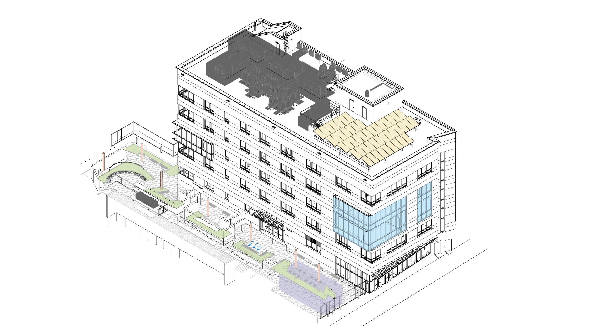
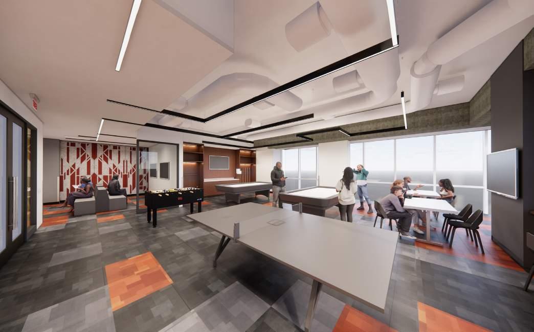
CUNY and Medgar Evers College retained MAD to design a new 60,000 Sq.ft Student Center for the campus in Brooklyn. MAD worked directly with CUNY and MEC to design the full student center fit out and exterior plaza landscape, leading a team of a dozen consultants. The design team coordinated with the SCA team who are responsible for the building core and shell. The Student Center is targeting LEED Gold certification, designed as an all-electric building with rooftop photovoltaics. Spaces include a 170-seat theater, a subdividable 300-person multipurpose room, classrooms, and a multitude of student amen-
LOW-EMITTING MATERIALS
USE OF INTERIOR BUILDING FINISHED AND MATERIALS THAT ARE RED-LIST FREE AND MEET LOW-EMITTING CRITERIA.
INDOOR WATER USE REDUCTION
WATER CONSUMPTION IS 40% BELOW EPAct AND SURPASSES LOCAL LAW REQUIREMENTS BY USING LOW FLOW PLUMBING FIXTURES.
STORAGE AND COLLECTION OF RECYCLABLES
DEDICATED RECYCLING ROOM FOR THE COLLECTION AND STORAGE OF RECYCLABLE MATERIAL STREAMS.
DARK SKY COMPLIANCE
EXTERIOR LIGHTING MEETS THE REQUIREMENTS FOR DARK SKY COMPLIANCE WITH THE GOAL OF REDUCING LIGHT POLLUTION
EXTERIOR PLAZA
PAVED PLAZA SLOPES TO DRAIN RUNOFF RAINWATER INTO VEGETATION.
DETENTION TANK
STORMWATER MITIGATION
ANTICIPTED LEED GOLD CERTIFICATION FOR COMMERCIAL INTERIORS

ENHANCED INDOOR AIR QUALITY STRATEGIES
MERV 13 FILTRATION OF RECRICULATED AIR TO OCCUPIED SPACES THROUGHOUT THE BUILDING
ELECTRIC-ONLY BUILDING
ALL DAY TO DAY MECHANICAL SYSTEMS ARE ELECTRIC ONLY. A DIESEL GENERATOR IS INSTALLED FOR EMERGENCIES.
RENEWABLE ENERGY PRODUCTION
10% OF BUILDING’S ENERGY IS PRODUCED BY ON-SITE SOLAR PANELS INSTALLED AT ROOF.
EXTERIOR GLAZING
WINDOWS ARE TRIPLE PANED FOR ENERGY EFFICIENCY AND BIRD-SAFE TO PREVENT HARM TO THE ECOSYSTEM.
INTERIOR LIGHTING AND DAYLIGHT
DAYLIGHT HARVESTING AND DIMMING FOR 90% OF OCCUPIED SPACES
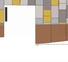
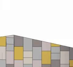
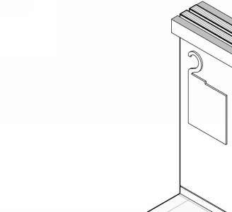
PARTITION
ACOUSTIC PANEL CORE
DASHED LINE INDICATES FABRIC WRAPPED PANEL
Z-CLIP OR SIMILAR
ACOUSTIC PANEL - ELEVATION / SECTION
PARTITION
ACOUSTIC PANEL CORE
DASHED LINE INDICATES FABRIC WRAPPED PANEL
Z-CLIP OR SIMILAR
FABRIC SELECTION - CARNEGIE


EXPOSED STRUCTURE ABOVE

BASWA ACOUSTIC CEILING
LIGHT COVE
WALL MOUNTED SPEAKERS
ACOUSTIC PANEL (TYPE A)
ACOUSTIC PANEL (TYPE B)


SIDE WALL

1/4” ROUNDED WOOD STRIP
WOOD PANEL
RECESSED BASE
SECTIONAL ELEVATION
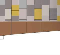
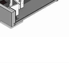
2” HEADER, TYP. ACROSS UNIT


ALL EXPOSED CABINET SURFACES & SHELVES
INDICATES LINE OF CABINET BEYOND
SCHEDULED C-TOP
3/4” FINISHED REVEAL WITH EDGE PULL TYP.
ADJUSTABLE SHELF
SIDE & BACK PANEL
SOFT CLOSING 180 CONCEALED CASEWORK HINGES
FIN. FLOOR
SECURE TO SLAB ABOVE
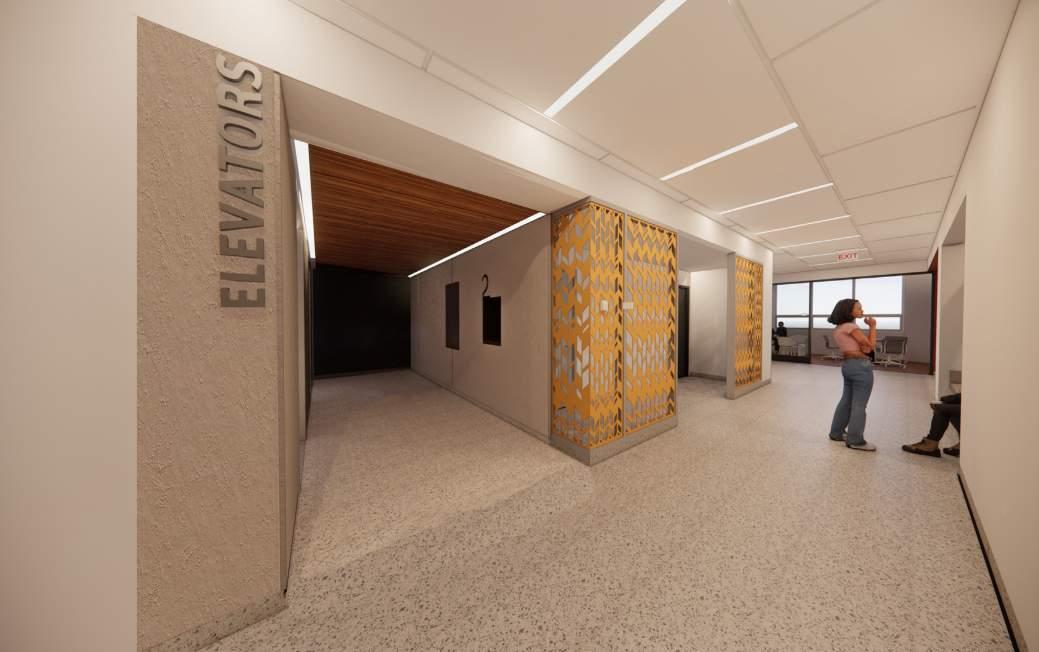
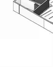
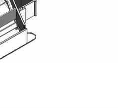
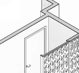
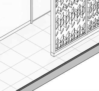
PARTITION
PLASTER FINSIH
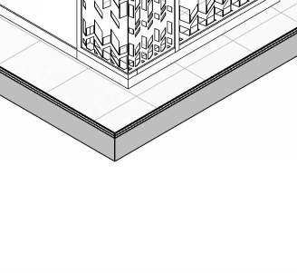
METAL LASER CUT PANEL
PRE-CAST TERRAZZO BASE 3/8” TILE TERRAZZO FLOOR 5/8” MORTAR BED
VAPOR BARRIER 1” TOPPING SLAB
EXISTING STRUCTURAL SLAB
PROVIDE LATERAL BRACING AS REQD.
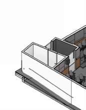
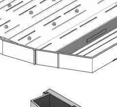
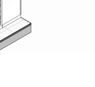
METAL
ALUM. STOREFRONT SYSTEM AT TOP & BOTTOM OF SCREEN AS SPEC.
METAL LASER CUT PANEL
SEALANT
FIRE TREATED BLOCKING AS REQD.
CONCRETE CURB. ANCHORED TO SLAB
TERRAZZO TILE FLOOR & BASE

ALUM. STOREFRONT SYSTEM AT TOP & BOTTOM OF SCREEN AS SPEC.
CURB BEYOND
FIRE TREATED BLOCKING AS REQD.


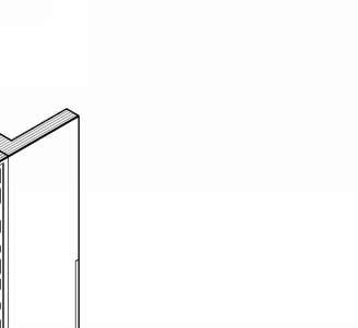
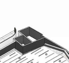
ALUM. STOREFRONT SYSTEM AT TOP & BOTTOM OF SCREEN AS SPEC.
15/18 G.STEEL SCREEN AS PER SPECS
ALUM. STOREFRONT SYSTEM AT TOP & BOTTOM OF SCREEN AS SPEC.
TERRAZZO TILE FLOOR
PROFESSIONAL PRACTICE, HIGHER EDUCATION, 2023, Project Manager
Tools- Revit, Illustrator, Enscape
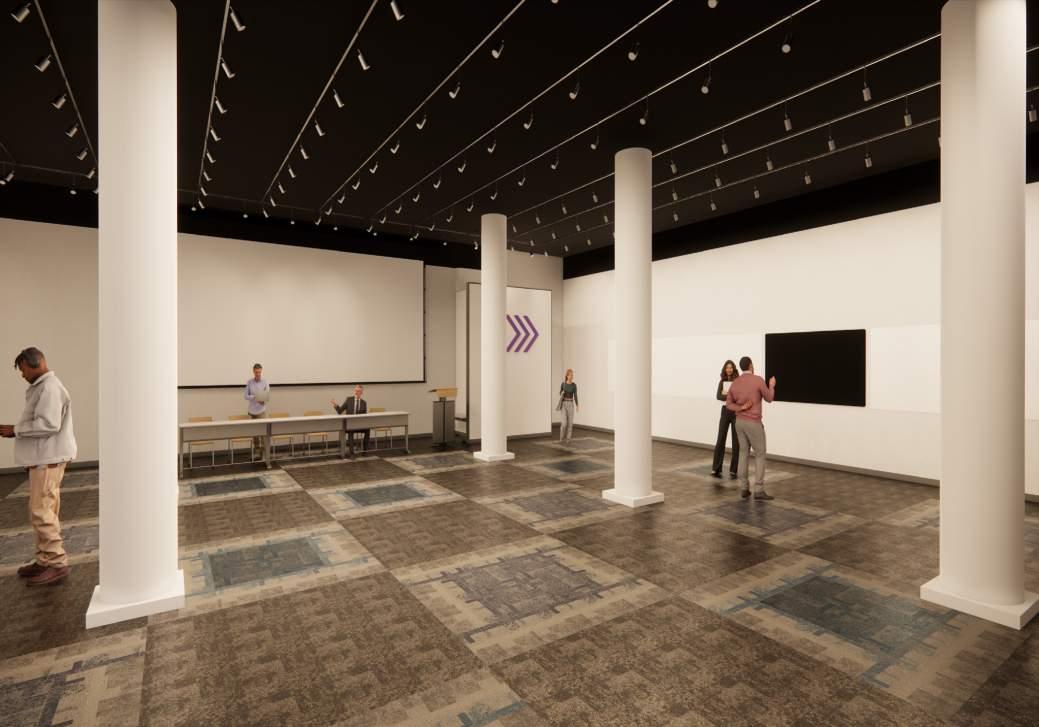
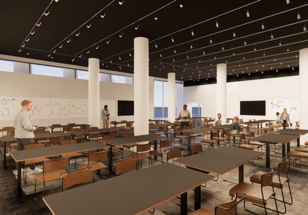
NYU retained MAD to redesign a space used as a seminar room to an active learning space. As the project manager , research of how an active learning classroom is different from a regular classroom was crucial and made us realize - they are spaces configured to maximize active, collaborative learning and multimodal teaching, in contrast with traditional lecture-style classrooms.
Spatial characteristics - movable chairs and tables, portable white boards, multiple viewing screens, varied levels of computer/electronic technology, and are arranged with no definitive front of the classroom.

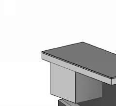
GC TO PROVIDE MTL. FRAMING AS REQD.
1" PAINTED WOOD CAP
PARTIAL HEIGHT PARTITION, SEE TAG & SCHEDULE FOR DETAILS. 5" 1" BLOCKING AS REQD. C:\Users\Thwisha
REVEAL ON BOTH SIDES(1/4")
FINISHED DRYWALL CORNER BEAD, TYP. ALL EDGES
GC TO PROVIDE MTL. FRAMING AS REQD.
1" PAINTED WOOD CAP
BLOCKING AS REQD.
1"
REVEAL ON BOTH SIDES(1/4")
FINISHED DRYWALL CORNER BEAD, TYP. ALL EDGES
PARTIAL HEIGHT PARTITION, SEE TAG & SCHEDULE FOR DETAILS.
A-501 12
12 WALL CAP DETAIL
SEE PLAN FOR PARTITION TYPES
2" SOUND ATTED INSUL., AS SCHEDULED
5/8" PTD GWB
4" RUBBER BASE (SEE FINISH SPECS FOR INFO)
7/32" CARPET TILE
1/4" THK LUAN/ FIRE RATED PLYWOOD
EXISTING WOOD FLOOR
EXIST. SLAB
11 FLOOR & CEILING DE
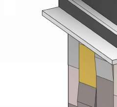
5/8" PTD GWB, FIRE RATED "BOX" ALL SIDES AND TOP
3/4" THK FIRE TREATED PLYWOOD ABOVE 4" 18g STUDS
2" SOUND ATTED INSUL., AS SCHEDULED
5/8" PTD GWB
DOWNLIGHT LF-2 (SEE LIGHTING SCHEDULE)
5/8" PTD GWB
SEE PLAN FOR PARTITION TYPES
2" SOUND ATTED INSUL., AS SCHEDULED
5/8" PTD GWB
4" RUBBER BASE (SEE FINISH SPECS FOR INFO)
7/32" CARPET TILE
1/4" THK LUAN/ FIRE RATED PLYWOOD
EXISTING WOOD FLOOR 4"
EXIST. SLAB
5/8" PTD GWB
1/4" THK DALTILE STONEWALL COAL CM09 -MATTE TILE (SEE FINISH SPECS FOR INFO)
1/4" REVEAL
4" DEKTON SIRIUS BLACK TILE (SEE FINISH SPECS FOR INFO)
DEKTON SIRIUS BLACK TILE (SEE FINISH SPECS FOR INFO)
PROFESSIONAL PRACTICE, 2024, Team
Tools- Research Analysis, AutoCAD, Illustrator
Carlyle Court is a three-building complex located directly adjacent to Union Square. The dormitory houses approximately 740 primarily sophomore students across the three buildings, which were built in 1986. This study focuses on Carlyle III, which is the largest of the three buildings.
Initial scope of work for exterior façade and envelope upgrades:
• Existing windows and balcony doors at a typical student room in Carlyle 3 (mock-up) will be evaluated for replacement on a per building basis (one typical room type included).
• Typical window at mock up location for C3. New replacement windows will be reconfigured as best as possible to meet improved safety requirements, operability, energy code compliance, and capacity & visibility of new VRF units placed located at balcony. C3 windows to be the base standard developed for all three buildings. Deliverables will be documentation for preliminary pricing, not for construction.
• VRF-VRV Mechanical Unit Mock- up; Existing conditions, such as electric panel capacity and size/clearance of the existing balcony encourage added study.
• Insulate the exposed concrete slabs at underside/from below, and determine the feasibility of this option with the existing (exposed concrete slab/non-waterproofed) balcony.
EXISTING ELEVATION
EXISTING ELEVATION
EXISTING ELEVATION
EXISTING PARTIAL FLOOR PLAN
DOTTED LINE (3) SERVING 1
ADJACENT
ROOM & 2
DOTTED LINE (3) SERVING 1 ADJACENT
ACROSS THE
ROOM & 2
ACROSS THE HALL
SERVING THE MOCKUP UNIT
TO ADJACENT UNIT (FUTU
TO ADJACENT UNIT (FUTU
EXISTING PARTIAL FLOOR PLAN
EXISTING PARTIAL FLOOR PLAN
TO (2) FCU IN MOCKUP UNIT
TO (2) FCU IN MOCKUP UNIT
EXTERIOR UNIT FOR UNITS G & H
REFER TO MEP FOR REQ'D CLEARANCES
EXTERIOR UNIT FOR UNITS G & H
REFER TO MEP FOR REQ'D CLEARANCES
NO PENETRATION OF PIPING THROUGH CONCRETE COLUMN
NO PENETRATION OF PIPING THROUGH CONCRETE COLUMN
SERVING THE MOCKUP UNIT
EXACT LOC.
TBD
EXACT LOC.
TBD
HVAC MODEL REQUIRES REDUCTION FROM 4 ACH TO 1 ACH
1. a) WINDOW - DOOR TO WINDOW REPLACEMENT
HVAC MODEL REQUIRES REDUCTION FROM 4 ACH TO 1 ACH
2. a) INFILL AT PTAC (OPENING ONLY)
1. a) WINDOW - DOOR TO WINDOW REPLACEMENT
EXISTING 97 SF
TO UNITS ON STREET SIDE (E & F)
TO UNITS ON STREET SIDE (E & F)
2. a) INFILL AT PTAC (OPENING ONLY)
b) INFILL AT DOOR
3. INSULATE SLAB
b) INFILL AT DOOR
4. INSTALL 1 VRF PER UNIT ( 37” x 12 5/8” x 39”)
3. INSULATE SLAB
5. AIR SEALING AT INTERIOR
4. INSTALL 1 VRF PER UNIT ( 37” x 12 5/8” x 39”)
6. FRESH AIR OPENING - 1 PER FCU (CODE REQ.D)
5. AIR SEALING AT INTERIOR
6. FRESH AIR OPENING - 1 PER FCU (CODE REQ.D)
NOTE: RAILING NOT SHOWN FOR LEGIBILITY
NOTE: RAILING NOT SHOWN FOR LEGIBILITY
PROPOSED ELEVATION
GLASS AREA WITH BALCONY DOOR REMOVAL
PROPOSED 85 SF
REQUIRED MEETS MIN. REQUIRMENT FOR LIGHT & AIR
EXISTING 97 SF PROPOSED 85 SF REQUIRED MEETS MIN. REQUIRMENT FOR LIGHT & AIR GLASS AREA WITH BALCONY DOOR REMOVAL
REFERENCE ROUTING: SIGNAL WIRING & REF. PIPING FOR MOCKUP UNIT FOR ADJACENT UNITS
REFERENCE ROUTING: SIGNAL WIRING & REF. PIPING FOR MOCKUP UNIT FOR ADJACENT UNITS
PROPOSED PARTIAL FLOOR PLAN
NOTE: REFER TO PCE’S NARRATIVE FOR FLOOR MOUNTED / VERTICAL STACK UNIT.
NOTE: REFER TO PCE’S NARRATIVE FOR FLOOR MOUNTED / VERTICAL STACK UNIT.
PROPOSED PARTIAL FLOOR PLAN
WINDOW:
The HVAC upgradIe requires more energy efficiency than will be able to be achieved with the existing windows, and therefore the function of the VRF capacity is the driving factor for window replacement.
INFILL PTAC GRILLE:
It is necessary to infill the PTAC existing opening masonry where this will be replaced as part of the HVAC upgrade.
AIR SEALING:
The HVAC upgrade (limited VRF capacity) requires that the energy efficiency of the building envelope be improved significantly. We recommend the addition of an air barrier (and possibly interior insulation) to all areas of the exterior walls areas where construction occurs in addition to the infill at the PTAC units.
BALCONY:
The existing balconies are reinforced concrete slabs, with curbs at the fascias to support the painted metal guardrail. There is an in slab drain at each balcony, but otherwise there is no membrane. Any added material to the balconies from the 3rd floor to the roof would need to allow for drainage at the underside, unless the top is consistently waterproofed, otherwise the added material could compromise the integrity of the slab by retaining moisture.
1
VRF FOR ADJ. UNIT (NOT PART OF MOCKUP)
INFILL EXISTING OPENING WITH STUD OR MASONRY WALL
PROPOSED VRF UNIT (37" x 12 5 8" x 39")
PAVERS OVER RIGID
PROPOSED WINDOW
1
UNDERSIDE INSULATION OR CLADDING UNLESS
MEMBRANE
ADDED TO TOP INSULATION NO
EXISTING RAILING CURB
PIPING FOR ADJACENT UNIT
NEW ALUM. SILL, SASH AND FLASHING WITH NEW WINDOW INSTALLATION
ENCLOSED PTAC OPENING
1
MTL. PANEL OVER 2" RIGID INSULATION
EXISTING BRICK FACE, REINSTALLED AFTER INSULATION AND FLASHING(TYP)
GRADUATE DESIGN STUDIO, SEMESTER 2, 2022, Team
Instructors: Jeffery Anderson, Carlos B Gerardino
Tools- Illustrator, Rhino, CNC Milling, Robotic Arm Prinitng, Basic Arduino Coding
Contemporary urbanism must consider more than just the form of cities because we exploit resources at a global scale. The exploitation of resources like air, water, energy, and organic materials expands well beyond the physical boundaries of the city. Even with the advancement in technology that has transformed urban protocols, it still largely remains outside the practices of urban planners and architectural designers. Unless the commons are managed, people take advantage of it. Hence, the question that we are addressing in the studio is:
Can Architecture manage resources around it?

Carbon Niwas aims to domesticate the idea of carbon capture. It is a climate literacy-led installation that surrounds people around an installation that sequesters atmospheric carbon by sensing human movement. The prototype addresses interaction and revelation. It is a project that continues to sequester carbon the longer a user engages with it. This engagement explores possibilities to include carbon as a building material and aesthetic.
CORE
The Robotic printed module holds the mixture of Potassium Hydroxide and Water. It has two tubes :
1. Air Input (Causes the bubbling effect once movement is triggered)
2. Air Output (Absorbs the air from the core) SKIN AIR

ULTRASONIC DISTANCE SENSOR
It senses the movement within 2 feet of the object and triggers the air pump
NEW STRUCTURE
MUSEUM ENVELOPE, INTERACTIVE WALL
OLD STRUCTURE ADAPTIVE RE-USE OF BARRACKS ON
CIRCULATION

SPATIAL ORGANISATION
ARTICULATION IN THE STRUCTURE
MUSEUM FACILITIES
EXHIBITION SPACE
OVERALL WORKSHOP AREA
GRADUATE DESIGN STUDIO, SEMESTER 1, 2021, Team
Instructors: Ariane Harrison, Yuxiang Cheng, Carlos B Gerardino
Tools- Illustrator, Rhino, Photoshop, 3D Printing, Casting
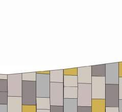
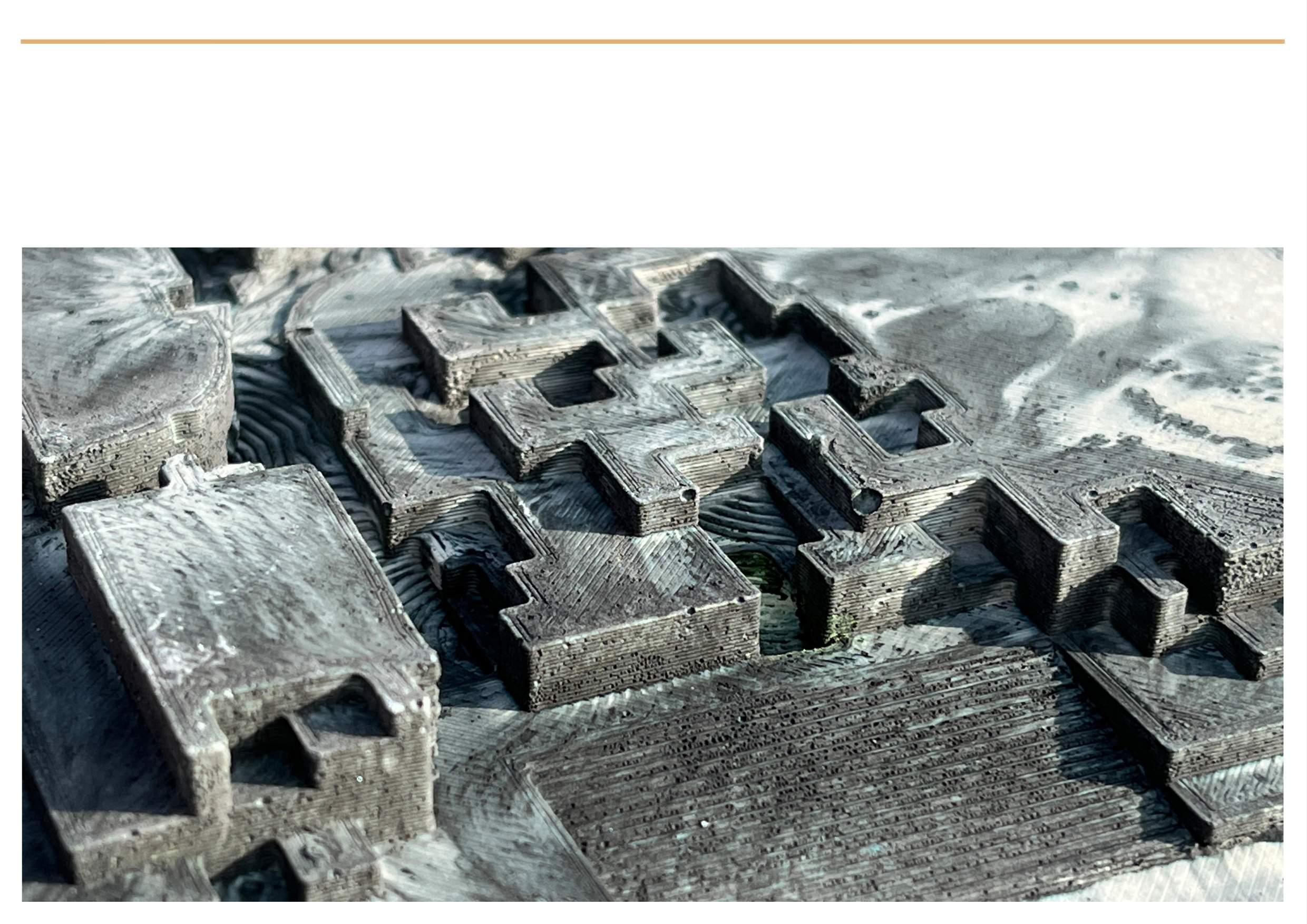
The presence of carbon, as both an architectural form and as an atmospheric material, is one marker of climate change. The construction industry contributes 40% of global carbon emissions. Reducing the carbon footprint of construction could entail not only more sustainable construction, but also a more public conversation about this material. Governors Island can offer a new exhibition landscape that uses the eastern development zone to showcase carbon’s role as a productive material, from bio-char filters for water to carbon-sequestering materials. The architectural envelope needs to be significantly expanded to confront carbon.
The existing barracks on Eastern Development Zone act as a canvas to showcase different phenomenon of global warming due to the abundance of carbon in the environment. Modifying that fabric allows us to adapt and reuse the already built and expanding the exhibit landscape above the ground.
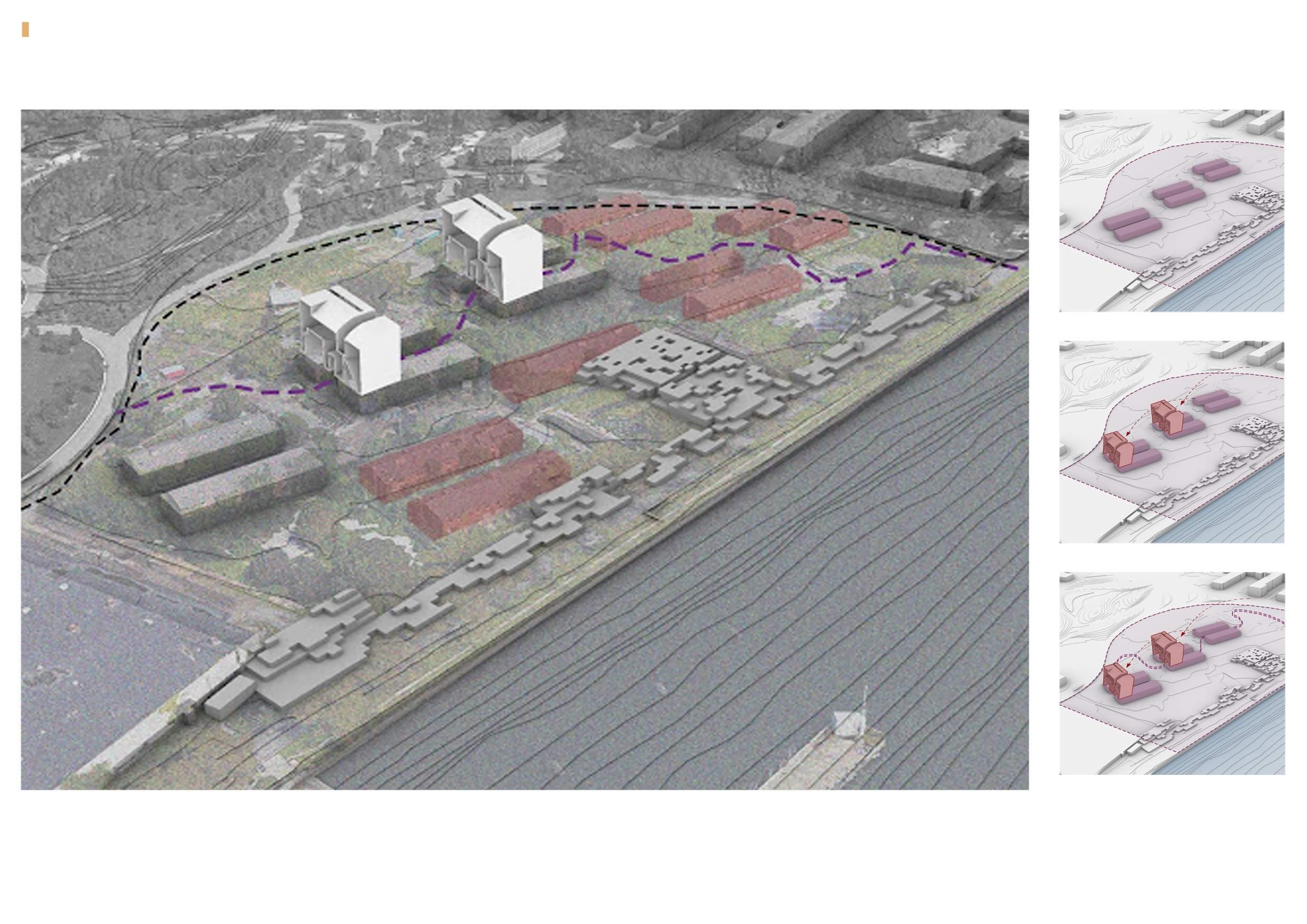
ADAPTING BARRACKS
EXTRACTION OF CO2
INTRODUCING PATHWAY
1 Turbine = 1660 cu.ft of CO2 per year = 6 Blocks
1 Block uses 25 cu.ft of CO2
40 Turbines = 66400 cu.ft of CO2
In 1 year: 40 turbines will produce 66400 cu.ft of CO2 which will be used to make 2656 blocks.
Annually the project generates carbon equivalent to build 5300 sustainable concrete blocks.
40 turbines that absorb the air and capture CO2.
ENTRY TO STRUCTURE

BARRACKS
They host the required services for the functioning of the turbines and mixing cement with CO2
UNDERGRADUATE SEMESTER 6 & COMPETITION AT GREEN ANGLE, 2017 Tools- Sketchup, VRay, Photoshop
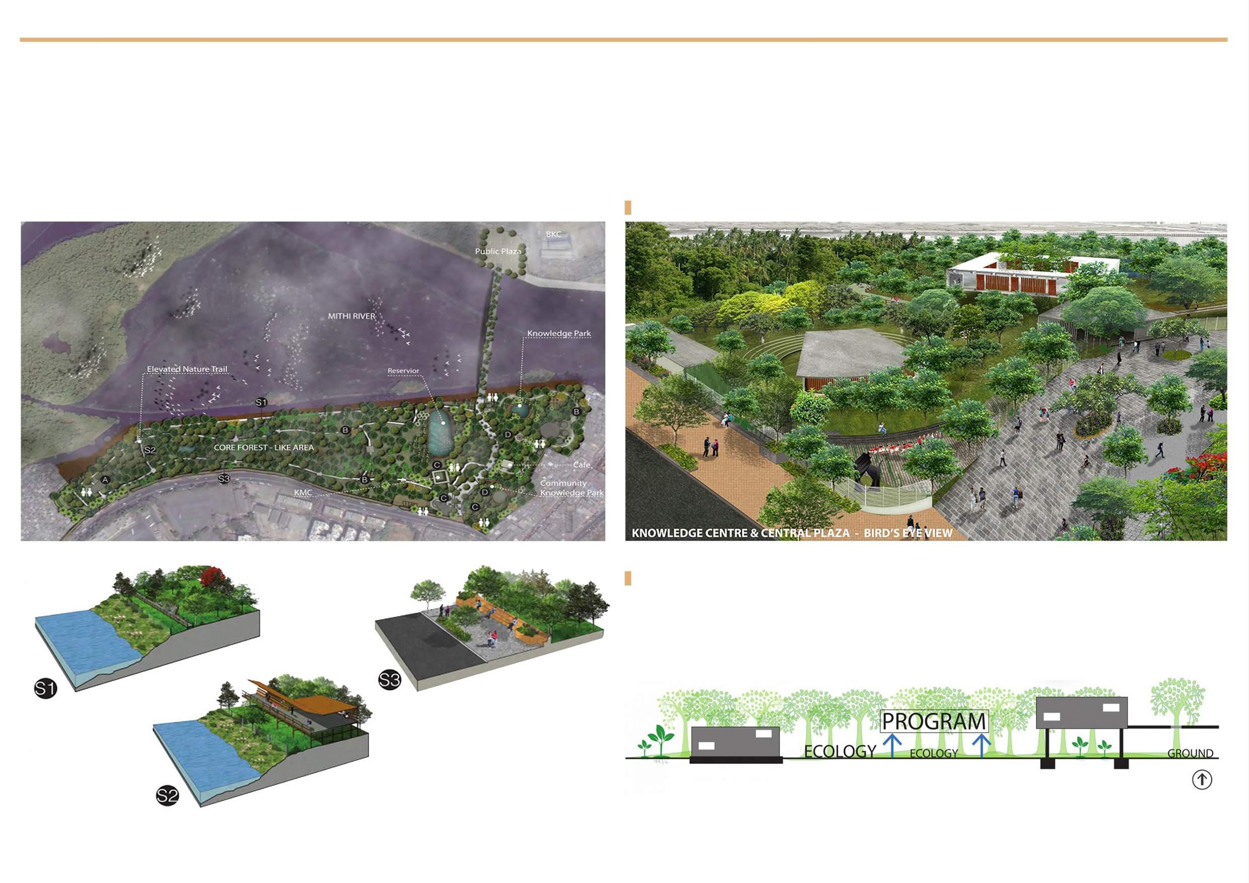
A Nature park for Mumbai is a great opportunity to enhance the quality of life for people from all walks of life. It is a space where nature dominates over human intervention. A great city with a hectic lifestyle needs an enchanting experience of nature, to appreciate it and learn to respect it by methods of preservation. It is an opportunity to add a little sensitivity in the lifestyle of the city. Maharashtra Nature Park is envisaged as the future hub for this vision for Mumbai.
VISION: ENHANCE, EXPAND, CONNECT
VIEWS
ECOLOGICAL STRATEGY
The Ecological Strategy is to elevate almost all built infrastructure which would reduce the green footprint of the forest like zone. By this idea we not only preserve the natural settings but also spread it across a larger area. The bold expression of the lift is subdued by the lightness of the design.

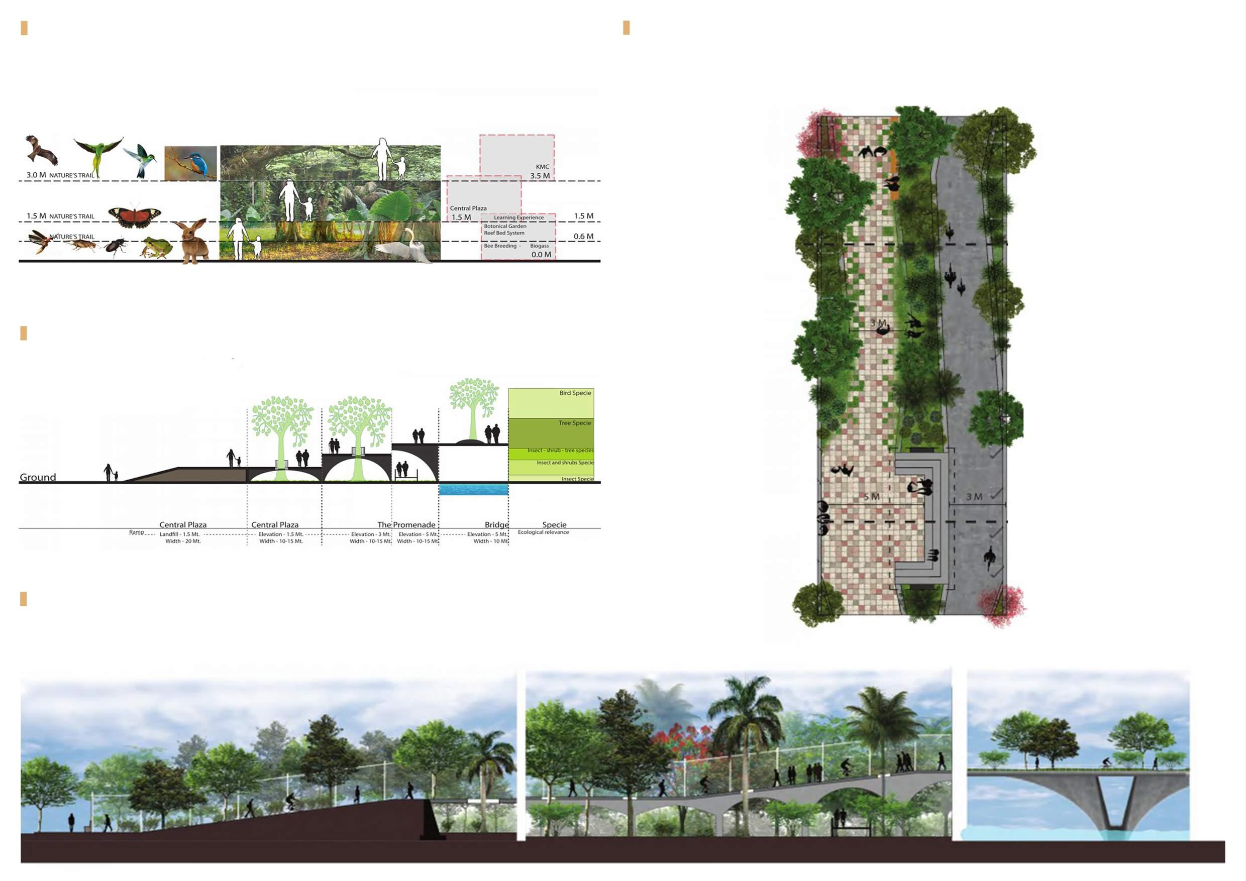
The experience of the elevation is a bold step to disassociate from the ground but at the same time offers many different experience levels where we generally miss the visuals of the detail. Infact by dissociating them we bring them more closer to nature.
The Bridge not only connects the two parts of the city but also the parks of the city. The existing parks in Bandra Kurla Complex and the side of MNP are connected by the promenade bridge, the bridge is not just a commuter experience but an enchanting experience of the setting around it and on it.
IMAGE OF THE LIVING ROOM
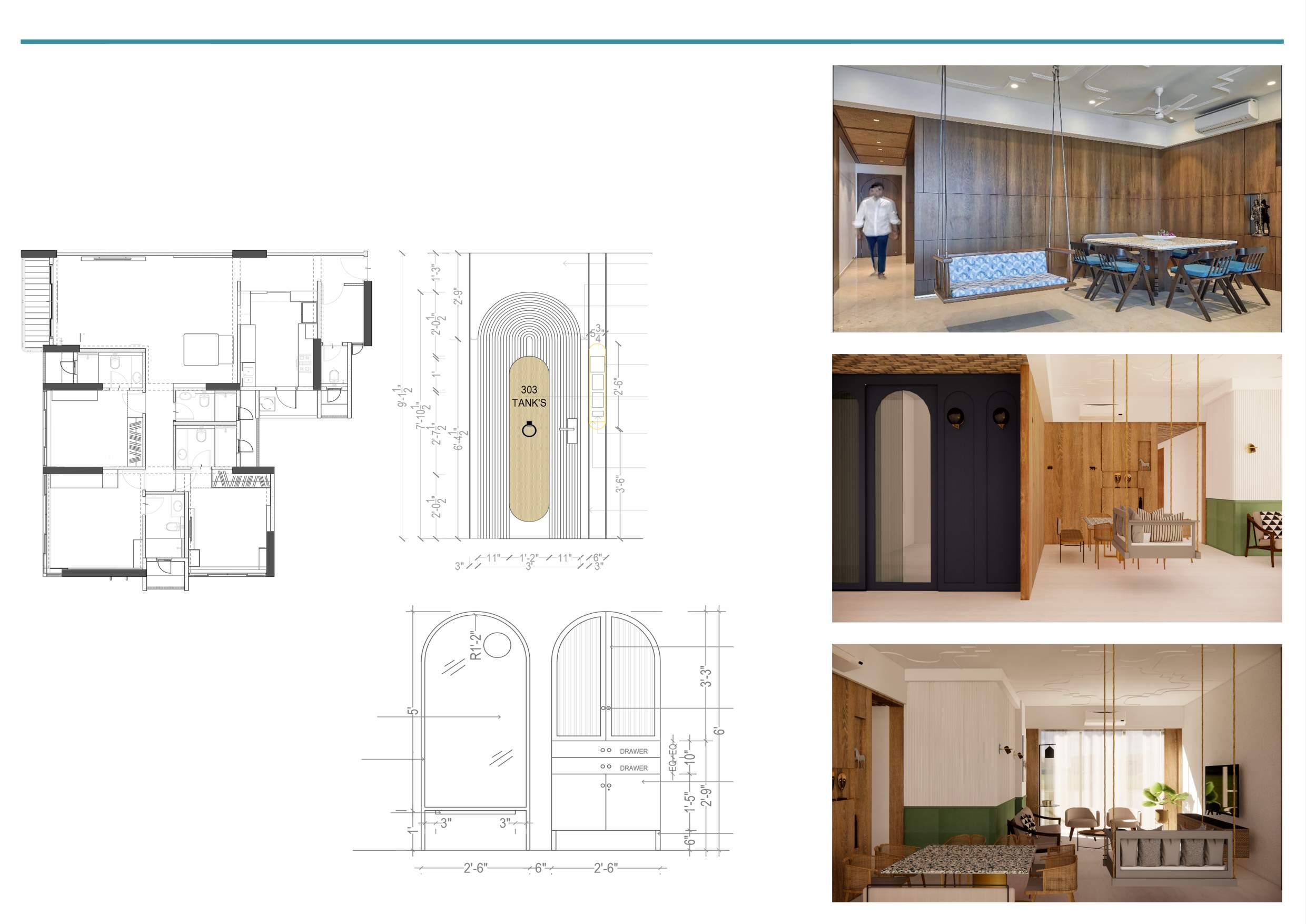
PROFESSIONAL PRACTICE, RESIDENTIAL, 2020, Team Tools- Photoshop, AutoCAD, SketchUp, Enscape
The client brief was to design the interior of the house with a modern theme along with a touch of Indianness. Hence, this concept was executed by the use of materials and furniture pieces. There was a substantial use of cane in the ceiling of the passage with moulding and wardrobes. To break the monotony of the neutral colour scheme, we used a bold blue colour in the entrance passage which proved to be the highlight of the entire apartment.
PLAN
DOOR ELEVATION
VENEER CLADDING WITH POLISH VENEER JOINT
DOOR TO BE CLADDED IN VENEER, FINISHED IN POLISH FLUTED PANELS ON MAIN DOOR
3” INSET FOR THE IDOL RATTAN CANE USED ON THE FASCIA SUPPORTED BY PLY ON THE BACK INSET CREATED TO SHOVE THE VDP, CAMERA & IDOL D-3”, W-5.5”, H-2’6”
6mm BRASS PATTI TO BE CLADDED ON THE VENEER PANELLING
KITCHEN PARTITION RENDER
LIVING ROOM RENDER
2” WIDE WOODEN FRAME WITH FLUTED GLASS INFILL
KNOB HANDLES
MIRROR INFILL
1” DIA WOODE FRAME, POLISHED
MARBLE LEDGE, FIT TO BACK PLY WITH ‘L’ SUPPORT
ALL SHUTTERS, BODY & DRAWERS IN PU FINISH
1“ DIA WOODEN LEGS, POLISHED
PROFESSIONAL PRACTICE, NIKHIL MAHASHUR & ASSOCIATES, Team Tools - SketchUp, Lumion, Photoshop
It was a phenomenal experience to work on this high-rise residential projectto be constructed in the most prime location of South Mumbai. Hence, this 48 storey building is one of its kind. Except the fact that the current building is in a very dilapidated condition, there had been various other challenges in terms of context, location and bye-laws. Thus, to have a design which was self-sustaining was necessity. The site area is around 20,500 sq.ft. The idea was to accomodate the existing 48 tenants and 28 commercial commercial tenants, as well as design luxurious residential flats for sale. After much brainstorming, each floor has a carpet area of 3000 sq.ft and at no point consists of more than 5 flats per floor. The entire construction process was planned based on the BIM technology targeting a platinum rated green building.
STAGE 1:
At first the concept of stepped planning was proposed, inspired by the Trump towers in London. Since the brief was majorly to cover the 360 degree panoramic view.

STAGE 2:
As we went ahead with zoning, we came across the dead corners beside the core. Hence, the dead corners were removed which add more ventilation to the building.
STAGE 3:
Second major issue was about having privacy. Since were unsure about the end users culture we decided to make the facade without any projections.
