
Introductiontopressurecastinganddiecastingmoldstructure
1.Definitionandcharacteristicsofpressurecasting
Die-casting:pourmoltenorsemi-moltenmetalintopressurechamberofdie-castingmachine,fill itincavityofdie-castingmold(die-castingtype)ataveryhighspeedunderactionofhigh pressure,meltitunderhighpressureorsemi-moltenmetalcoolingandsolidificationtoobtain castings.
Advantagesofdiecasting:
1.Highdimensionalaccuracyandlowsurfaceroughness
2Highutilizationrateofmaterials
3.Itcanformcomplexstructure,thin-walledanddeep-cavityparts
4Die-castingpartshavecompactstructure,highstrengthandhardness
5Highproductionefficiency,suitableformassproduction
6Partsofothermaterialscanbeembedded
Diecastingdisadvantages:
1.Diecastingsarepronetopores,andexpansionofgasinporesathightemperaturewillcause bubblingonthesurfaceofdiecastings
2.Moldcostishigh,notsuitableforsmallbatchproduction
3Sizeofdie-castingmachineislimited,anditisdifficulttodie-castlargedie-castingpartsdueto limitationofclampingforceofmachineandsizeofmold.Forcastingswithcomplexconcaves, die-castingproductionisalsodifficult
4.Typesofdie-castingalloysarelimited.Duetouseoftemperaturerestrictions,lifeofdie-casting diesforhigh-meltingpointalloys(suchasferrousmetals)islow
Diecastingalloymaterialselectionprinciples:
1Canmeetperformancerequirementsofproductusescenarios
2.Ithassufficienthightemperaturestrengthandplasticity,andthermalbrittlenessissmall
3Crystallizationtemperaturerangeissmall,fluidityisgood,tendencytoproduceporesand shrinkagecavitiesissmall
4Shrinkagerateisassmallaspossible,tendencyofhotcracking,coldcrackinganddeformation issmall
5Tendencyofphysical-chemicalinteractionwithcavitywallissmall
6Goodprocessingperformanceandcertaincorrosionresistance
Currentlycommonlyuseddie-castingalloysarezincalloy,aluminumalloy,magnesiumalloy, copperalloy,tinalloy,leadalloy
2.Structuralrequirementsofdiecastings
Whendesigningstructureofdiecastings,followingpointsshouldbeconsidered:
1.Compactnessofthin-walledcastingsisbetter
Aswallthicknessincreases,defectssuchasinternalporesandshrinkagecavitieswillalsoincrease
Underpremiseofensuringsufficientstrengthandrigidityofcasting,thicknessshouldbereduced asmuchaspossibleanduniformthicknessshouldbeensured
Recommendedwallthicknessdesignvaluesfordiecastingsareasfollows:
Zincalloy AluminumalloyMagnesiumalloyCopperalloy Wallthicknessh(mm)

smallestnormalsmallestnormalsmallestnormalsmallestnormal
2.Forconnectionpositionofwallsurface,roundedcornerconnectionshouldbedesignedas muchaspossibletoavoidstressconcentrationRecommendeddesignvaluesareasfollows:
2DemouldingangleshouldbeaslargeaspossibleRecommendeddemouldingangleisas followsSomezincalloyplaneswithsmallareascanachievezero-degreedraft
3Avoiddeepandsmallholes,narrowanddeepgroovesinstructuraldesignSeetablebelowfor relatedprocesscapabilities.

Alloy Minimumholediameterd(mm)Depthisamultipleofapertured

Followingprinciplesshouldbeconsideredwhenselectingproductpartingsurface:
1Apartingschemethatiseasytoprocesscavityshouldbeselected,andcore-pullingmechanism shouldbeminimized.
2Inordertomakedie-castingpartstayinmovablemoldaftermoldisopened,duringdesign, tightnessofdiecastingonmovingmoldcoreisgreaterthanthatoffixedmodelcore,and tightnessofcastingoncoreisgreaterthanthatofshrinkageofcastingonthecore
3.Sidecorepullingshouldbesetonmovablemoldasfaraspossible,sothatwhenmoldis opened,corepullingandleavingfixedmoldcanbecarriedoutatthesametime,whichsimplifies moldstructureOtherwise,corepullingactionmustbecompletedbeforemainpartingsurface canbeparted
4Topreventpartingsurfacefromaffectingdimensionalaccuracyofcasting,keysizepartsand partswithhighshapeandpositiontolerancerequirementsshouldbesetinsamehalfmold.
5Partingsurfaceshouldavoidcoincidencewithmachiningreferenceplaneofcasting
6.Considerappearancerequirementsofcastingtoselectpartingsurface
7PartingsurfaceshouldchooseapositionthatisconducivetofillingandformingAtthesame time,itisrecommendedtosetitatlastfillingpartofmoltenmetal,soastofacilitateexhaustand slagdischargeofproduct
8.Choiceofpartingsurfaceshouldfacilitateinstallationofinsertsandmovablecores.
3Diecastingmachinestructure

Die-castingmachinesaremainlydividedintohot-chamberdie-castingmachinesand cold-chamberdie-castingmachinesHot-chamberdie-castingmachinesbasicallyonlyhave horizontalstyles,whilecold-chamberdie-castingmachinesaredividedintohorizontal,vertical, andfull-verticalEquipmentfeaturesandapplicationscenariosareasfollows:

Diecastingmachineclassification
EquipmentFeatures
Cold Chamber Die Casting Machine
1.Pressurechamberandheat preservationcrucibleareseparated Duringdiecasting,itisnecessaryto takeoutmetalliquidfromheat preservationfurnaceandpouritinto pressurechamberbeforediecasting Heatlossislarge,operationis cumbersome,andproduction efficiencyisnotasgoodasthatofhot chamberdiecastingmachine.
2Workingenvironmentofpressure chamberofcoldchamberdie-casting machineisbetter,andalarge-pressure horizontalinjectioncylindercanbe used,whichissuitableformedium andlargedie-castingmachines.Itis mostlyusedfordie-castinghigh meltingpointalloys,andcanbeused fordie-castinglarge-scalecastings
Aluminum alloy Magnesiu malloy Copper alloy Black metal
pressure
Hot Chamber
Die Casting Machine
pressurechamberandinjection mechanismarehorizontal,pressure chamberisparalleltodirectionof moldmovement.;
Verticalpressurechamberis perpendiculartoinjectionmechanism, andpressurechamberisperpendicular tomovementdirectionofmold; Fullyverticalinjectionmechanismand moldclampingmechanismareina verticalposition,andpressure chamberisparalleltomovement directionofmold.
Advantagesofhorizontaldiecasting machinearehighpressure,convenient maintenanceandhighefficiency Disadvantageisthatsurfaceareaof moltenmetalexposedtoatmosphere islarge.Whenprocessparametersare notselectedproperly,itiseasytoget involvedinair,oxidesorother impurities,itisnotconvenientfor insertdie-casting.
Advantageofverticaldie-casting machineisthatitoccupiesasmall area,butstructureisrelatively complicated,operationand maintenanceareinconvenient,which affectsproductionefficiency
Advantageoffull-verticaldie-casting machineisthatmoldisplaced horizontally,soitisconvenientto installinsertsDisadvantageisthat structureiscomplicated,partsare morecomplicated,andproduction efficiencyisnothigh.
1.Pressurechamberisimmersedin liquidmetalinheatpreservation
crucible,andinjectionpartsare installedoncrucible
2Simplestructure,convenient operation,simpleproductionprocess, noneedforseparatefeeding,high efficiency,easytorealizeautomatic
production,butitisinconvenientto replacepressurechamber,and injectionspecificpressureissmallItis mostlyusedfordie-casting low-meltingpointalloysand miniaturizedcastings.
3Die-castingmoltenmetalenters moldcavitydirectlyfrompressure chamber,temperaturefluctuation rangeofmoltenmetalissmall,heat lossissmall,airorimpuritiesarenot easilybroughtin,purityofmolten metalishigh,die-castingprocessis stable,andcastingqualityisgood
4.Comparedwithcoldchamberdie castingmachine,pouringsystem consumeslessrawmaterialsandsaves costs
5.Pressurechamberandotherparts areimmersedinmoltenalloyliquidfor alongtime,whichiseasilycorroded, affectsservicelife,andmayincrease ironcontentofcasting.
Workingprincipleofhotchamberdie-castingmachineandcoldchamberdie-castingmachine (horizontal,vertical,fullvertical)isshownbelow:

Workingprincipleofhotchamberdiecastingmachine
Workingprincipleofhorizontalcoldchamberdiecastingmachine


Workingprincipleofverticalcoldchamberdiecastingmachine
Workingprincipleoffullyverticalcoldchamberdiecastingmachine 4Die-castingmoldstructure
Asetofdie-castingmoldsgenerallyconsistsoffollowingparts:

Structuralcompositionofdie-castingmold
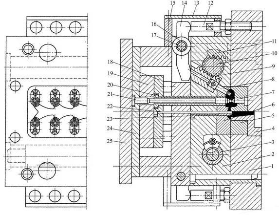
1pushplate;2pushrodfixedplate;3pad;4limitstop;5pullrod;6gasket;7nut;8 spring;9sideslider;10wedgeTighteningblock;11-obliquepin;12,27-cylindricalpin; 13-movablemoldinsert;14-sidecore;15fixedmoldinsert;16-fixedmoldseatplate;17,26, 30-hexagonsocketscrews;18-spruesleeve;19-guidepost;20-guidesleeve;21-core;22fixedmoldcoverplate;23-movablemoldcoverplate;24-supportplate;25,28,31-pushrod: 29limitingnail:32resetrod;33pushplateguidesleeve;34pushplateguidepost;35 movingmoldbaseplate

SystemArchitectureofDieCastingMold
1Moldingsystem
Itconsistsofacavity,afixedcore,amovablecore,etc
2Gatingsystem
Itconsistsofsprue,horizontalsprue,innergate,etc
3.Overflowsystem

Consistsofoverflowtank,exhausttank,etc
4.Demouldingsystem
Itconsistsofpush-outelements(pushrods,pushtubes,unloadingplates,etc),resetelements (resetrods,inclinedsliders,etc.),limitelements(limitblocks,limitnails,etc.),guideelements (guidepillars,guidesleeves,etc),structuralelements(pushplate,pushrodfixingplate,etc)
5.Corepullingsystem
Itconsistsofformingelements(sidecores,inserts,etc),movingelements(sidesliders,inclined sliders,etc.),transmissionelements(obliquepins,racks,hydrauliccorepullers,etc.),locking elements(lockingblocks,Wedgeblocks,etc),limitcomponents(limitblocks,limitnails,etc)
6.Supportsystem
Itiscomposedoffixedmoldbaseplate,fixedmoldplate,movablemoldplate,movablemold
supportplate,moldbase,ejectionplate,guideparts,etc.
7Heating/coolingsystem
Composedofheatingandcoolingoil/watercircuits
Followingisabriefintroductiontoeachpart:
1.Formingsystem
Moldingsystem:Partsthatformformingcavitytoformgeometricshapeofdie-castingarecalled formingparts,whichdeterminequalityandprecisionofdie-casting,andalsodetermineservice lifeofdie-castingmoldFormingsystemincludescavity,fixedcore,movablecore,etc
Formingsystemisdividedintointegraltypeandmosaic(combined)structure
Integraltype,thatis,coreandcavityaredirectlyprocessedonmoldplate
Inmosaictype,cavityandcorearemadeofasinglepieceofmaterial,thenloadedintomold sleeveofmoldbase,thenfixedwithshouldersorbolts
Monolithicstructure
1-fixedmoldcoverplate;2-fixedmoldbaseplate;3-guidebush;4-gatesleeve;5-combinedinsert; 6-integralinsert;7-castinsert


Mosaicstructure
Duetolargeamountofstructuralprocessing,integraltypeisnoteasytomaintain,difficultto heattreatmentandsurfacetreatment,soitisonlysuitableformoldsortestmoldswithsmall batches,shallowcavities,lowprecisionrequirements,andlowalloymeltingpoints
Mosaicmoldingstructureiswidelyusedindie-castingmolds
Designprinciplesofmosaicmoldingsystem:
1Formedpartsshouldbeeasytoprocessandensuredimensionalaccuracy,fitaccuracyand structuralstrength.
2Avoidsharpedgesandthinwalls
3.Directionofinlaidgapshouldbeconsistentwithdirectionofmoldrelease
4Itshouldbeeasytomaintainandreplace
5.Doesnothinderappearanceofcastings,andisconducivetoremovalofflash 2Gatingsystem
Gatingsystemismainlycomposedofsprue,runnerandinnergate.Differenttypesofdie-casting machineshavedifferentgatingsystemsDifferencesareasfollows:
Verticalcoldchamberdiecasting machine Horizontal cold Hotchamber diecasting
Fullverticaldiecasting machine
Diecasting machinetype

Hotroom
Structurediagram


chamber
diecasting machine
machine
Verticalcold room
Illustrate
Itconsistsofsprue,inner gate,lateralrunner, diverterconeandoverflow tank(notshowninfigure).


Sincepressurechamberis placedincrucible,after injectioniscompleted, injectionpunchmoves upwardtoformanegative pressureinpressureair, whichsucksuninjected moltenmetalbackinto gooseneck channel, resultinginlesspouring residue
Itissomewhatsimilarto pouringsystemofhot chamberdie-castingmold, exceptthatmaterialcake isproduced
1-straightflowchannel;2-crossflowchannel;3-innergate;4-remainingmaterial;5-splittingcone nestHorizontal coldroom
Fullvertical coldroom
Sprue:directpassagefrommoldgatingsysteminlettorunner

Thisisthemostcommonly usedforminpractice, consistingofsprue, runner,ingate,overflow troughandexhaust channel.

Sinceitisfedfrombelow, thecakeappearsinthe lowerpartofthepouring systemandthediverter coneisintheupperpart
Forcoldchamberdie-castingmachine,sprueismainlycomposedofpressurechamberof die-castingmachineandspruesleeveondie-castingmold,andalloycondensateonsprueis calledremainingmaterial
1-Nozzle;2-Spruesleeve;3-Diverter;4-Remainingmaterial
Forhotchamberdie-castingmachines,sprueisgenerallycomposedofnozzlesondie-casting machine,spruesleevesandsplitterconesondie-castingmold
1-nozzle;2-gatesleeve;3-runner
Spruesleeve(nozzle):Aroundsleeve-shapedpartformingasprue,generallyembeddedinfixed moldseatplate,oneendisconnectedtonozzle,andtheotherendisconnectedtofixedmold


insert.Useofspruesleevecansavemoldsteelandeasytoprocess.
Splittercone:aconicalpartthatisassembleddirectlyagainstspruetodivertmoltenmetaland changeflowdirectionsmoothly.Itisusedtoadjustcross-sectionalareaofrunnerandchange flowdirectionofmoltenmetalForasplitterconewitharelativelylargediameter,pushrodscan besetatthecenterorsymmetricallyalongcenter.

Runner(runner):passagefromtheendofspruetothefrontofingate
Itsfunctionistointroducemoltenmetalfromsprueintoingate,andpreheatmoldwiththehelp oflargevolumeofmoltenmetalinrunnerWhencastingcoolsandshrinks,itisusedtofeed shrinkageandtransmitstaticpressureSometimesrunnercanbedividedintomainrunnerand transitionrunner

Mainrunnerandtransitionrunner
1-Mainrunner;2-Transitionrunner

Keypointsofrunnerdesign:
1.Cross-sectionalareaofrunnershouldbekeptuniformorgraduallyreducedfromsprueto ingate,andshouldnotchangerapidlyItisrecommendedthatcross-sectionalareaofexitbe reducedby10%-30%comparedtoentrance.
2Forexpansionfan-shapedrunner,ratioofentrancetoexitgenerallydoesnotexceed1:15,and openinganglemustbe<90°
3Runnershouldbestraightorhaveaslightreversebeveltoavoidairentrainmentorunstable flow.
4Forsmallandthincastings,methodofusingrunnersorexpandingrunnerscanbeusedto

makemoldreachthermalbalance,andblindrunnerscanbeaddedtoaccommodatecolddirty metalliquid,paintresiduesandgases
5.Cross-sectionalareaofrunnershouldnotbesmallerthancross-sectionalareaofinnergate underanycircumstances
6.Whentherearemultiplecavities,trytoadoptasymmetricallayout,makefillingprocess conditionsofeachcavityasconsistentaspossible,andfilleachcavityatthesametimeasmuch aspossible.Whentypesofdie-castingpartsineachcavityaredifferent,cross-sectionalareaof eachingateshouldbecalculatedanddeterminedseparately,andinitialsizeofcross-sectional areashouldbeselectedtobesmaller,soastofacilitateadjustmentandcorrectionofsubsequent moldtrial
Ingate:Asectionofrunnerfromtheendofrunnertocavity
Therearemainlyfollowingcategoriesofgates:
1Sidegate
Openonpartingsurfaceofmold,feedingfromoutsideorinsideofthelargestcontour
Itisgenerallysuitableforplatedie-castingpartsorcoverandshellpartswithnottoodeepcavity
Productswithacertaindepthgenerallyadoptendfacelapjointfeeding
Advantages:simplemolddesignandstructure,easygateremoval,widelyusedindie-casting products
Disadvantages:Whenfeedingdirectlyfromoutside,moltenmetalislikelytosealpartingsurface first,whichmakesitdifficulttodischargegasincavityandformpores
2Directgate(topgate)
Atypeofgatingsysteminwhichsprueisdirectlysetatoutercenterofbottomofshellorcylinder diecastingConnectionwithcastingisingate,whichisalsoplacewiththelargestcross-sectional areaingatingsystem,whichisconvenientforfeedingattheendofdie-castingandholding pressure

Advantages:goodflowstateofmoltenmetal,shortprocess,smoothexhaust,andsumof projectedareaofgatingsystem,overflowgrooveanddiecastingonpartingsurfaceisthe smallest,moldstructureiscompact,nozzleslagisless,andforceisuniform.
Disadvantages:heatjointsareformedatjunctionofdiecastingandsprue(nodeorlocalareain castingthatsolidifiesslowerthansurroundingmetalcanalsobesaidtobetheplacewiththe highesttemperatureandlastcoolingplace,whichispronetoshrinkage,shrinkagecavitiesand
shrinkagestressconcentration)
Gateresidueislarge,anditisdifficulttoremoveGenerally,mechanicalprocessingisusedto removeit.


Sincemoltenmetalenterscavityfromlargeendofsprueandthenrushesstraightintocavity,itis easytocausestickingofmoldandaffectlifeofmold
3Centergate
Itisaspecialformofdirectgate.Whenthereisasmallthroughholenearcenterofproduct, ingateislocatedatthroughhole,andasplitterconeissetinthemiddleMoltenmetalenters cavityinaringshapeatthebottomofdiecasting
Advantages:Ithassameadvantagesastopgate,andatthesametime,therewillbenoshrinkage cavityduetothermaljointsatdirectgatefeed
Disadvantages:Itisdifficulttoremovegate
4Pointgate
Aspecialform,forsomedie-castingpartsthatarebasicallysymmetricalorcenter-symmetricalin shape,uniformandthininwallthickness,smallinsize,smallinheightandhavenoholeinthe centeroftop,pointgatescanbeused
Advantages:Ithasthesameadvantagesastopgate,andatthesametime,therewillbeno shrinkagecavityduetothermaljointsatdirectgatefeed
Disadvantages:Cross-sectionalareaofgateissmall,flowrateofmoltenmetalislarge,itiseasy tocausesplashing,andmoldstickingoccursnearinnergate
Atthesametime,inordertotakeoutcondensateofgatingsystem,apartingsurfaceneedstobe addedtofixedmold,fixed-distancesequentialpartingmechanismisadopted,andmoldstructure isrelativelycomplicated.

5.Ringgate
Mainlyusedincylindricaldiecastings,aisringgateofdirectfeeding,bisringgateoftangential feeding,lessused.

Advantages:Ithasaveryidealfillingstate,smoothexhaust,pushrodscanbesetatringgateand overflowgroove,sothatnothimblemarksareleftonproduct
Disadvantages:Consumptionofmetalrawmaterialsislarge,itisdifficulttoremovegate,moldis oftendesignedasasplittype,andmoldstructureiscomplicated.
6Slotgate
Similartosidegate,differenceisthatdimensionofdepthdirectionofinnergategreatlyexceeds dimensionofwidthdirection,andgateisshapedlikealongstripgap
Advantages:fillingstateisbetter,whichisconducivetopressuretransmission


Disadvantages:Inordertofacilitateprocessing,moldgenerallyalsoneedstobesplitlaterally
Ingatelocationdesignprinciples:
1Importedmoltenmetalshouldfirstfilldeeppartofcavitythatisdifficulttovent,anditisnot
suitabletoimmediatelysealpartingsurfacetocausepoorventing
2Moltenmetalflowingintocavityshouldminimizetwistsandturns,avoidexcessiveeddy currents,andreducewrappinggas
3Positionofinnergateshouldmakeflowofmoltenmetalasshortaspossibletoreduceenergy lossandtemperaturedropofmoltenmetalduringfillingprocess.
4Positionofgateshouldmakedistancebetweenmoltenmetalflowtoeachpartofcavityas equalaspossible,soastoachievesimultaneousfillingandsolidificationofeachdividedpart 5Itisgenerallyinstalledatthickwallofdiecasting,whichisbeneficialtopressuretransmission offeedingflowaftermoltenmetalfillscavity
6Trytouseasingleinnergateanduselessbranchgatestoavoidmutualimpactwhenmultiple channelsofmoltenmetalconverge.Whenmultiplebranchgatesmustbeused,careshouldbe takentopreventmultiplechannelsofmoltenmetalfromcollidingwitheachothertoformeddy currents,resultingindie-castingdefectssuchasairentrainment,oxideinclusions,andcoldshuts
7Considerationshouldbetakentoreducediversionofmoltenmetalincavity,preventdiverted moltenmetalfromcausingcoldjointmarksorcoldshutsattheconfluence
8.Trytoavoidmetalliquidrushingdirectlyintocavity,reducekineticenergyloss,preventerosion andmoldsticking,especiallyavoidimpactingsmallcoresorthreadedcorestopreventbending anddeformation.
9Ingeneral,whencastingisthinandrequiresaclearoutline,athinneringateshouldbeusedto ensuresufficientfillingspeed,buttoothinaningatewillleadtoseriousinjectionofmoltenmetal andbeeasilyblockedbyimpuritiesAtthesametime,moltenmetalenteringcavityisproneto atomization,whichblocksexhaustchannelandcausespittingandporesonthesurfaceofcasting. Forpartswithgeneralshapes,itisrecommendedtouseathickeringate,whichisbeneficialto reducefillingspeedandtransferfeedingpressure.However,ifingateistoothick,fillingspeedwill betoolowandcoolingwillbelarge,whichmayleadtounclearcontoursofcasting,anditwillbe troublesometoremoveingate.
10Itisnotadvisabletoarrangeingateswhereprecisionrequirementsarehigh,surface roughnessvalueislow,andpartsthatarenotprocessedshouldbearrangedtopreventleaving tracesafterremovinggates
11Settingofingateshouldconsiderdistributionoftemperaturefieldofmoldsothatfarendof cavitycanbefilledwell
Commonempiricalformulaforingatesizedesign:
Ringparts,cylindrical
Framepieces
3Overflowsystem
Overflowsystemismainlycomposedofoverflowgroove,exhaustgroove,togetherwithgating system,itisaninseparablewholeincavityfillingprocess
Overflowgroove(slaggingbag):itisusedtopushcondensedmetalliquid,gas,oxidationresidue andotherimpuritiesatthefrontendtogrooveoutsidemoldcavity,soastoincreaselocal temperatureofmoldandachieveagoodandorderlyfillingprocess.Whenoverflowgrooveis openedonmovablemoldside,pushrod(thimble)canbeplacedonoverflowgroove
1-overflowport;2-overflowgroove;3-pushrod;4-exhaustgroove

Principlesforsettinglocationofoverflowtank:
1Setanoverflowtankonlastfillingpartofalloyliquid
2.Whenalloyliquidisdividedintotwostrands(ormorethantwostrands)duetoobstructionof core,anoverflowtankshouldbeprovidednearcavity
3.Anoverflowgrooveshouldbeprovidedforcavityoflocalthickboss
4Whenthereisapartofcavitythatislocallythin,inordertoincreaseheatofcavityatthat place,anoverflowgrooveshouldbeprovidednearplace.
5Overflowgrooveshouldbesetonbothsidesofingateorindeadangleareawheremolten metalcannotbefilledsmoothly,soastoplayroleofdrainageandfilling
6Trytoavoidopeningmultipleoverflowportsononeoverflowtanktoavoidbackflowofmolten metal.
7Whendesigningoverflowtank,payattentiontoconvenienceofpost-processingremoval,and trynottoplaceitonappearancesurface,soastoavoidpost-processingaffectingproduct appearanceInprinciple,underproductperformancerequirements,overflowtankshouldbe addedaslittleaspossibleConsiderincreasingandreducingpost-processingworkload
Suggestedoverflowtankvolumesize:
ConditionsofUse Volumerange Illustrate
Eliminateshrinkage cavitiesatlocalhot spotsindiecastings
Thetotalvolumeof overflowtank
Itis3-4timesofhotspot,or 2-25timesofvolumeof defectivepart.
Notlessthan20%ofdie castings
Ifitisusedasaheatsourcefor equilibriumtemperatureorusedto improvefillingflowpatternofmolten metal,itsvolumeshouldbeincreased
Smalldiecastingshavealargerratio
Therearemainlythreetypesofcross-sectionalshapesofoverflowtanks:
Exhaustgroove:Itisusedtopushgasincavitytoairflowgrooveoutsidemoldcavity,whichis convenientforproductfilling.Itusuallycooperateswithoverflowgrooveandisarrangedatthe backendofoverflowgroovetoenhanceeffectofslagdischargeandexhaust Mainpointsofexhaustgroovedesignareasfollows:

1Locationofexhaustgrooveisbasicallysameasthatofoverflowgroove,anditshouldbeseton partingsurfaceasmuchaspossibletofacilitatedemoulding
2Exhaustgrooveshouldbesetonsamemoldhalfasmuchaspossibletofacilitateprocessing 3Whenexhaustvolumeislarge,numberorwidthofexhaustslotscanbeincreased,and thicknessshouldnotbeincreasedtopreventmoltenmetalfromcloggingorsplashingoutwards 4Exhaustslotsshouldbeopenedattheendofoverflowtank
5.Thetotalcross-sectionalareaofexhaustgrooveisgenerallynotlessthan50%ofthetotal cross-sectionalareaofingate,butmustnotexceedthetotalcross-sectionalareaofingate
6.Whenusingzigzagexhaustgrooves,inordertoreduceexhaustresistance,turningwidthcan betwicethewidthofnormalexhaustgrooves,andlengthofnormalexhaustgroovesshouldnot belessthan15-25mm.
7.Straight-throughexhaustgroovecanbemadeintoasteppedshape,deepenedto1.5times thickness,ormadewithaslopeof15',orprojectionshapeonpartingsurfacecanbemadeinto anenlargedhornshape

Recommendedventsize:

Exhaustslotsize
Alloytype
Leadalloy 005-0108-25
Zincalloy 005-012
Aluminumalloy0.10-0.15
Magnesium alloy 0.10-0.15
Copperalloy 015-020
Blackmetal 020-030
4Ejectionsystem
1Afterexhaustgrooveleavesmoldcavity 20-30mm,itsdepthcanbeincreasedto 03-04mmtoimproveitsexhausteffect;
2Whenitisnecessarytoincreaseareaof exhaustgrooves,itisadvisabletoincrease widthandnumberofexhaustgroovesItisnot advisabletoincreasetheirdepthexcessivelyto preventleakageofmoltenmetal
Ejectionsystemismainlycomposedofejectionelements(pushrod,pushtube,dischargeplate, etc),resetelements(resetrod,inclinedslider,etc),limitelements(limitblocks,limitnails,etc), guideelements(guidecolumn,guidesleeve,etc.),structuralelements(pushplate,pushrod fixingplate,etc),functionistoreleasecastingfromformedpart
Compositionoflaunchorganization
1-Limitnail;2-Resetrod;3-Pushrod;4-Pushtube;5-Pushplateguidesleeve;6-Pushrodfixed plate;7-Pushplate;8-Pushrodguidepost

Push-outdistanceisgenerallydeterminedaccordingtoheightofprotrudingpartingsurfaceof movablemold,asshowninfigurebelow
WhenH≤20mm,St≥H+K
WhenH>20mm,1/3H≤St≤H
Kissafetyfactor,take3-5mm
Formoldswithsplittercones,ifheightofsplitterconeprotrudingfrompartingsurfaceisgreater thanheightofmoldingpart,push-outdistanceshouldbeconsideredaccordingtoheightof
splittercone.
Keypointsforsettingpushrodpushingposition:
1Pushrodsshouldbedistributedreasonablysothatallpartsofcastingareevenlystressed
2.Castinghasadeepcavityandapartwithalargetighteningforce.Diameterandquantityof pushrodshouldbeselectedAtthesametime,pushrodalsohasfunctionsofexhaustand overflow
3Avoidsettingpushrodonimportantsurfaceordatumsurfaceofcasting,andsetpushrodon overflowtank.
4Whennecessary,pushrodshouldbearrangedreasonablyonrunnerWhenthereisasplitter cone,pushrodshouldbesetatthepositionofsplittercone
5Pushrodshouldbesetatpartwithgreaterdemouldingresistance,suchasedgeofsidewallof moldedpart,aroundcoreordeephole,butitshouldbeatleast3mmawayfromsideofcoreto avoidweakeningstrengthofcoreduetotoothinawall
6Pushrodshouldbesetinapartwithalargerthrustbearingcapacity
7PushrodshouldnotbetoothinWhendiameterislessthan8mm,asteppedpushrodshould beused
8.Ingeneral,inordertoensureflatnessofdiecasting,assemblyheightofpushingendsurfaceof pushrodshouldbehigherthanformedparth,buthshouldnotbetoolarge,otherwisedie castingmayadheretopushrod,hisgenerallytakenas0.05-0.1mm,nomorethan0.4mm.
Forthin-walleddie-castingparts,withoutaffectingassembly,thicknessofpush-outpartcanbe appropriatelyincreased,orendfaceofpushrodislowerthancoreh1=0.05-0.1mm,not exceeding02mm,soastoincreasestrengthofdie-castingpart


9.Trytoavoidsettingpushrodattheplacewhereinsertormovablecoreisplaced,otherwise pre-resetmechanismofpush-outmechanismmustbeset
10.Formoldswithsidecore-pullingmechanism,pushingpositionofpushrodshouldtrytoavoid movementinterferencewithresetactionofsidecore
11.Endofpushrodatthepositionofdiverterconeshouldbedesignedintheshapeofdiverter cone,soastoplaytheroleofdiverteratthesametimeasdivertercone
12Whensettingpushrodoninclinedsurfaceofdiecasting,inordertopreventrelativesliding duringpushingoutprocess,multipleparalleltransversegroovesshouldbesetonpushingend slopeofpushrod.

13Whendie-castingpartsarenotallowedtohavethimblemarksandtightnessisnotlarge,push rodscanbeinstalledatrunnersandoverflowgrooves
14Positionofpushrodshouldavoidwaterway
Typeofputter:
Endfaceshowninaisplanar,whichisthemostcommonlyusedform
Whendiameterofpush-outsectionislessthan8mm,tailcanbethickened,asshowninb
Endfacesshownincanddareconical,andatthesametimeofejection,itprovidesapositioning conepitfordrillingandalsoactsasadivertercone
Whateshowsispushrodsetononesideofreinforcingrib,onesideofwhichconstitutesapart offormingsideofreinforcingrib,andatthesametimeplaystheroleofpushingout.

fshowshookpushrodOnhorizontalcoldchamberdie-castingmachine,whenthereisno overhangingactiontopushoutremainingmaterialofrunner,usehookpushrodtorelease remainingmaterialofrunnerfromspruesleeve,thenpushoutremainingmaterial,runnerand diecastingtogetherwithpushrod4ondiecasting,asshowninfigurebelow.

5Corepullingsystem
Core-pullingsystem:Whenthereareundercutsontheoutsideorinsideofdie-castingandcannot bedemoldeddirectly,itisnecessarytodesignpartsatcorrespondingcharacteristicpositionsas movableparts.Mechanismthatresetsextractedmovablepartsandcompletesaboveactionsis core-pullingmechanism
Corepullingsystemgenerallyconsistsofformingelements(sidecores,inserts,etc.),moving elements(sidesliders,inclinedsliders,etc),transmissionelements(obliquepins,racks,hydraulic corepullers,etc.),lockingelements(Lockingblock,wedgeblock,etc.),limitingcomponents (limitingblock,limitingnail,etc)


Compositionofcorepullingmechanism
1-limitblock;2,8-clampingblock;3-obliquepin;4-rectangularslider;5,6-core;7-circularslider; 9-joint;10-stopblock
Core-pullingsystemdesignprinciples:
1.Coreshouldbesetinmovable(fixed)moldperpendiculartopartingsurfaceasfaraspossible, andcoreshouldbepulledoutbyopeningmoldorpushingout,avoidinguseofahuge core-pullingmechanismasmuchaspossible,andusingfixedmoldcore-pullingaslittleas possible
2.Atthepositionofslendermovablecore,trytoavoiddirectimpactofalloyliquid.
3Whencoreispulledouttofinalposition,lengthofsliderleftinguidechuteisgenerallynotless than2/3oflengthofslider,soastoavoidaccidentscausedbytiltofsliderwhencoreisclamped.
4Whenusingmoldopeningandclosingmovementastransmissionofcore-pullingmechanism, attentionshouldbepaidtoresetofmovablecoreandinterferenceofpush-outcomponents whenmoldisclosedGenerally,itisrequiredthatnopush-outcomponentsshouldbeinstalled withinprojectedareaofmovablecore,andhydrauliccorepullingshouldbestrictlyoperatedor safetydevicesshouldbeinstalled.
5Ontheplaneofslider,itisgenerallynotsuitabletoinstallagatingsystemIfagatingsystem mustbeinstalledonit,areasonablelayoutshouldbecarriedout,andplaneofslidershouldbe increasedtopreventgatingsystemfrombeingplacedonguide-slidingmatchingpartofsliderand moldbody,whichwillaffectnormaloperationofsidesliderontheonehand,andmakematching parthaveenoughthermalexpansiongap
6.Die-castingmoldsseldomuseinnerslidersorlifterblocks,becauseproductiontemperatureof die-castingmoldsishigh,moldexpansionislargeandthereisalotofdross,gapbetweenlifter andguideblockisverysmall,problemofstickingisveryeasytooccurduringproductionprocess, resultingincontinuousproductionofmold
Structuraldiagramofobliquepincore-pullingmechanism:
Compositionofsidecorepullingmechanism

1-movablemoldcoverplate;2-movablemoldinsert;3-sidecore;4-punch;5-fixedmoldinsert; 6-fixedmoldcoverplate;7-obliquepin;8-cylindricalpin;9-Sideslideblock;10-clampingblock; 11-tierod;12-stopblock;13-spring;14-washer;15-nut
Actionprocessofobliquepincore-pullingmechanism:
 Structuraldiagramofbentpincore-pullingmechanism:
Bendingpincorepullingmechanism
1-spring;2-limitingblock;3-columnscrew;4-clampingblock;5-bentpin;6-slidingblock;7-core Actionprocessofbentpincore-pullingmechanism:
Structureandactionprocessofinclinedslidercore-pullingmechanism:


Inclinedslidersidecorepullingmechanism
1-fixedmoldinsert;2-fixedmoldcoverplate;3-core;4-inclinedslider;5-pushrod;6-corefixed plate;7-limitscrewpin;8-movablemoldcoverplate;9-gatesleeve
Structuraldiagramofrackandpinioncorepullingmechanism:

6.Heating/coolingsystem
Heatingsystem:
Mainlyusedforpreheatingmold,orlocallyheatingmoldtemperaturearea
Whenpouringtemperatureishigh,fluidityofmoltenalloyisgood,andsurfacequalityofcasting isgood,butgassolubilityandoxidationinmoltenalloyareintensified,lifeofdie-castingmoldis short,anditiseasytocausestickingphenomenonforaluminumalloy
Whenpouringtemperatureislow,fluidityofmoltenalloyispoor,andsurfacequalityofcastingis poor,butitprovidesconditionsforuseofadeepexhaustchannel,therebyimprovingexhaust condition,andshrinkageisalsosmall,reducingpossibilityofshrinkageandporesinthickpart duetounevenwallthickness,alsoreducingerosionandstickingofmold,therebyprolonginglife ofmold.
Recommendedpouringtemperaturesforvariousalloysaregivenbelow:
Zincalloy
Aluminumalloy620-710
Thereareseveralheatingmethods:
Magnesiumalloy640-730
Copperalloy 910-960
1Flameheating,suchasblowtorchesandsprayguns,hassimplemethodsandlowcost,but flameheatingwilloverheatsurfaceofmoldbodyorraisedlocalarea,andinsufficientheatingof insideorconcavelocalareaofmoldbody,overheatingwillcausecavityofdie-castingmoldto softenandreducelifeofmold;
2Circulatingheatingwithheatmedium,usingcoolingwaterchanneltofeedhotoil,hotsteam andotherheatingmediumtoheatmoldincirculation,whichissimpletomanufactureandlowin cost;
3.Heatingwithmoldtemperaturecontroldevices,suchasresistanceheaters,electricinduction heaters,andinfraredheatersUsingmoldtemperaturecontroldevicescannotonlyeffectively controlmoldtemperature,butalsoprolongmoldlife;
4Heatingmethodoftubularelectricheatingelementsisgenerallyplacedonmovableandfixed moldsetsorsupportplates,andinstallationholesofelectricheatingelementsaresetaccording toactualneeds
Coolingsystem:
Duringdie-castingprocess,alloyliquidissolidifiedandcooledtopush-outtemperature,and releasedheatisabsorbedbymoldInordertomaintainbalancebetweenheattransferredinto moldandheattransferredfrommold,coolingsystemisoftenrequiredforforcedcooling Reasonabledesignofcoolingsystemcanincreaseproductivityofdiecasting,improvequalityof castingsandprolongservicelifeofmold.
Therearetwomainmethodsofmoldcooling:
1.Watercooling
Coolingwaterchannelissetinmold,andheatistakenawaybypassingwaterintomoldWater coolingefficiencyishighandeasytocontrol.
2Aircooling
Forparticularlyslenderandsmallcoreindie-castingmoldorpartsthataredifficulttousewater cooling,aircoolingmethodofcompressedaircanbeused
Coolingchanneldesignpoints:
1Coolingwaterchannelisrequiredtobearrangedintheareawiththehighesttemperatureand relativelyconcentratedheatincavity,runnermustbesmoothandfreeofblockage
2Distancefromcoolingwaterchanneltocavitysurfaceshouldbeasequalaspossible,distance betweenwaterchannelwallandcavitysurfaceisgenerally12-15mm
3Diameterofcoolingchannelholeisgenerally8-16mm,dependingonsizeandwallthicknessof diecasting
4Temperaturedifferencebetweenentranceandexitofwaterwayshouldbeconsideredassmall aspossibleduringdesign
5.Whencoolingwaterchannelpassesthroughtwoormoretemplatesorparts,sealingmeasures arerequiredtopreventleakage,andrubbersealingringsorsealingsheetsareoftenusedfor sealing.
6Waterpipejointshouldbesetasfaraspossiblebelowmoldoronsideoppositetooperator, anditsouterdiametershouldbeuniform
5.Diecastingprocessandprocessparameters
Diecastingisdividedintofollowingfourprocesses: a.Moldclosingb.Injectionc.Moldopeningd.Pushoutandreset
Themostcriticaloftheseisinjectionprocess:fromtimeinjectionpunchstartstomoveuntil cavityisfilledwithpressure(hotchamberdie-castingmachine),oruntilpressurizationends(cold chamberdie-castingmachine)
PressureandspeedaretwoimportantprocessparametersininjectionprocessDynamic characteristiccurvethatrecordspressureandspeedduringinjectionprocessiscalledinjection processcurve
Duringinjectionprocess,withdisplacementofinjectionpunch,speedandpressurechange accordingtosetpattern
Movementofliquidmetalinpressurechamberandcavitycanbedecomposedintofourstages.
Largeandmedium-sizeddie-castingmachinescurrentlyusedarefour-stageinjection,smalland medium-sizeddie-castingmachinesaremostlythree-stageinjection(secondandthirdstagesare combinedintoonestage),whilehotchamberdiecastingismainlybasedontwostagesof injection(first-speedliquidliftingandsecond-speedfilling)
Thefirststage:Fromstartingpositionofinjectionpunchtopositionbeyondgatingopening Features:Lowpressure,lowspeed,smoothmovement,preventsmoltenmetalfromoverflowing fromthepouringport,andfacilitatesgasdischarge
Thesecondstage:Frompositionbeyondgatetopointwheremoltenmetalfillsuptoinnergate Features:Aspressureincreases,speedofinjectionpunchincreases.Aftercrossingpouring opening,injectionpressureincreases,speedofinjectionpunchspeedsup,andmoltenmetalfills pressurechambertopouringsystem.Atthisstage,airentrainmentshouldbepreventedand moltenmetalshouldnotentermoldcavityinadvance

Thethirdphase:Frompointwheremoltenmetalfillsinnergatetothetimewhencavityis completelyfilled
Features:Injectionpressureincreasesagain,injectionspeeddecreasesslightly,andmoldfilling speedisthefastestSincecross-sectionalareaatinnergateisgreatlyreduced,flowresistance increasessharply,injectionspeeddecreasesslightly,butmoldfillingspeedisthefastestatthis time
Stage4:Chargingends
Features:Injectionpunchstopsmoving,andpressureincreasessharply,reachingthehighest
valueintheentireprocess.Aftercavityisfilled,boosterpressurepressessolidifyingmoltenmetal intochamberInjectionpunchmaymoveforwardslightlyAftermoltenmetalsolidifies,boost pressureisremovedandinjectionprocessends.
Duringdiecasting,therearemanyfactorsthataffectfillingandmoldingofmoltenmetal, includingpressure,speed,temperature,timeandotherparameters
1Pressure
Injectionforce:Workingfluidininjectioncylinderofdie-castingmachineactsoninjectionpunch, causingittopushmoltenmetaltofillmoldcavityThisiscalledinjectionforce Injectionforce

Pg-workingpressureininjectioncylinder,PaD-diameterofinjectioncylinder,m
Specificpressure:forceonunitareaofdie-castingalloyliquidinpressurechamber,thatis,ratio ofinjectionforceofdie-castingmachinetocross-sectionalareaofinjectionpunchSpecific pressureduringfillingiscalledinjectionspecificpressure.Whenthereisaboostermechanism, specificpressureaftersuperchargingiscalledsuperchargingspecificpressure,whichdetermines finalpressureondiecastingandsizeofexpansionforceformedatthistime.
Injectionspecificpressure
Expansionforce:Duringdie-castingprocess,whenmoltenmetalfillscavity,pressureexertedon cavitywallandpartingsurfaceiscalledexpansionforceDuringdie-castingprocess,finalstageof boostingspecificpressureistransmittedtodie-castingmoldthroughmoltenmetal.Expansion forceatthistimeisthelargestInordertopreventdie-castingmoldfrombeingexpanded, clampingforcemustbegreaterthanresultantforceofexpansionforceinmoldclosingdirection Expansionforce
A-Sumofprojectedareasofdiecastings,gates,andoverflowsystemsonpartingsurface
Choosingappropriatespecificpressurecanimprovemechanicalpropertiesofdiecastings
Whencastingsolidifiesunderahighspecificpressure,tinyporesorbubblesinsideitare compressed,densityandstrengthofinternalstructurearehigh.However,asspecificpressureis toohigh,plasticityindexofcastingdecreases,strengthalsodecreases,andmechanicalproperties decline.
Ahigherinjectionspecificpressurecanimprovemoldfillingabilityofmoltenmetal,prevent castingfromcoldshutorinsufficientfillingdefects,andmakeoutlineclearer.However,ifspecific pressureistoohigh,itwillintensifyimpactofmoltenmetalonmoldcavityandacceleratewear ofmold.Generally,alowerspecificpressureisselectedonthepremiseofensuringformingand userequirementsofdiecasting
2.Speed
Therearetwotypesofspeed:injectionspeedandgatespeed
Injectionspeed(punchspeed):speedatwhichinjectionpunchpushesmoltenmetal,whichis speedofinjectionpunch
Innergatespeed(fillingspeed):Linearspeedofmoltenmetalpassingthroughinnergateiscalled ingatespeed
Gatespeed
-Innergatespeed(m/s)
-Injectionspeed(m/s)
d-Injectionpunch(orpressurechamber)diameter(m)
-Innergatecross-sectionalarea
eta-resistancecoefficient,generally03-06
-Liquiddensityofalloy(kg/m3)
Injectionforceislarge,gatespeedishigh;alloyliquiddensityishigh,gatecross-sectionalareais large,andgatespeedislowDuringdie-castingprocess,innergatespeedcanbeadjusteddirectly orindirectlybyadjustinginjectionspeed,changinginjectionpunchdiameter,specificpressure andinnergatecross-sectionalarea
3.Temperature
Temperatureofdie-castingmainlyreferstoalloypouringtemperatureandtemperatureof die-castingmold.
Alloypouringtemperaturereferstoaveragetemperatureofdie-castalloyliquidwhenitenters moldcavityfrompressurechamber.Experiencehasproventhatwhenpressureishigh,pouring temperatureshouldbereducedasmuchaspossibleItisbesttodie-castwhendie-castingalloy liquidisviscousand"porridge-like",whichcanreducefluctuationofsurfacetemperatureof cavityanderosionofcavitybydie-castingalloyliquidHowever,foraluminumalloyswithhigh siliconcontent,itisnotadvisabletodie-castwhendie-castingalloyliquidis"porridge-like", otherwisealargeamountofsiliconwillprecipitateandexistinafreestateinsidecasting, worseningprocessingperformance.
Pouringtemperaturesofvariousdie-castingalloysvarydependingontheirwallthicknessand structuralcomplexity.Pleaserefertotablebelowfortheirvalues.
Pouringtemperatureofvariousdie-castingalloys(unit:℃)
Die-castingmoldmustbepreheatedtoacertaintemperaturebeforeuseFunctionofpreheating istoavoidthermalimpactofhigh-temperaturedie-castingalloyliquidoncold-pressurecasting moldandextendservicelifeofdie-castingmoldThesecondistopreventdie-castingalloyliquid fromquicklylosingfluidityduetoquenchinginmold,sothatcastingcannotbefilledsmoothly.
Forworkingtemperatureofdie-castingmold,pleaserefertotablebelow
4Time
Diecastingparametertime:1.Fillingtime2.Pressurizationtime(pressurebuildingtime)3. Pressureholdingtime(pressureholdingtime)4Moldretentiontime
Fillingtime:Timeittakesformoltenmetaltoentermoldcavityuntilitfillscavityiscalledfilling timeItslengthdependsonsizeandcomplexityofdiecasting,cross-sectionalareaofinnergate, speedofinnergate,etc
Boostingtime:Timerequiredfrommomentmoltenmetalfillsmoldcavitytoreaching predeterminedboostingpressure,thatis,timerequiredforspecificpressureinboostingstageto risefrominjectionspecificpressuretoboostingspecificpressure.Fromperspectiveofdie-casting process,theshorterthistimeis,thebetter,butminimumboostingtimeofamachinewithbetter performanceisnotlessthan0.01s.
Holdingtime:Timefromwhenmoltenmetalfillsmoldcavitytowheninnergateiscompletely solidifiedandpunchpressureactsonmoltenmetal.Ifholdingtimeisinsufficient,thickwallof castingthatisfinallysolidifiedwillnotbecompressed,resultinginshrinkageporositydefectsIf holdingtimeistoolong,castinghassolidifiedandpunchisstillapplyingpressure.Pressureatthis timenolongeraffectsqualityofcastingCommonlyusedholdingtimeinproductionisasfollows:
Moldretentiontime:periodfromendofpressureholdingtomoldopening.Ifmoldretention timeistooshort,castingwillbeeasilydeformedorcrackedduringdemouldingduetohigh temperatureandlowstrength.Ifmoldretentiontimeistoolong,productivitywillbeaffected,
andcastingtemperaturewillbetoolow,resultinginlargeshrinkage,increasedresistancetocore pullingandejectionofcastingHotbrittlealloyswillalsocausecrackingofcastingCommonmold retentiontimeforeachalloyisasfollows:
Commonlyusedmoldretentiontime/s
Selectionofprocessparametersindie-castingproductioncanbecarriedoutaccordingto followingprinciples:
1Ifproductionconditionsareconducivetofillingofalloyinmoldcavityandshrinkageor shrinkageholesofdiecasting,asmallerspecificpressurecanbeselected.Otherwise,alarger specificpressureshouldbeselected
2.Thethickerwallofcastingandthemorecomplexstructure,thegreaterinjectionforceshould be
3.Thethinnerwallofcastingandthemorecomplexstructure,thefasterinjectionspeedshould be
4.Thethickerwallofcasting,thelongerpressureandmoldretentiontimeshouldbe.
5Thethinnercastingwallandthemorecomplexstructure,thehighermoldpouring temperatureshouldbe.
6Analysisofdie-castingdefects
Therearemanydefectsindie-castingparts,andtheirformationiscausedbymanyfactors.Their classificationcanbemainlydividedintofollowingthreecategories:
1.Surfacedefects,poorappearanceofdiecastings,suchasstrains,flowmarks,coldinsulation, undercasting,burrs,etc
2Geometricdefects,shapeandsizeofdie-castingpartsdeviatefromtechnicalrequirements, suchasdeformation,dimensionaldeviation,deflection,etc
3Internaldefects,suchaspores,shrinkageporosity,shrinkagecavities,cracks,etc
Influencingfactorsgenerallyincludefollowingpoints:
1Causedbyalloymaterials,composition,cleanliness,ratio,smeltingprocess,etcofraw materialsandrecycledmaterials
2Causedbydie-castingmachine,whetherinjectionforce,injectionspeed,clampingforceare sufficient,whetherdie-castingprocessparametersareappropriatelyselected,etc.
3Causedbydie-castingoperations,alloypouringtemperature,meltingtemperature,paint sprayingamountandoperation,productioncycle,etc.
4Causedbydie-castingmold,moldstructure,pouringsystemsizeandposition,ejectorpinand layout,coolingsystem,etc.
5Causedbydie-castingdesign,die-castingwallthickness,roundedcorners,draftangle,hotspot location,deeprecess,etc.
Commondefects,characteristics,causesandimprovementplansofdiecastingcanbeseeninthe
followingtable:
Defect name CharacteristicsCause Improvementplan
StrainPartrubsmold during demoulding process, leavingtraces along demoulding direction
1Molddemouldingangleis small
2Cavitysurfaceisrough
3.Releaseagentisnotsprayed inplace/evenly
4.Partejectiondeflection.
5Alloybondingmold(iron contentinaluminumalloyisless than06%)
6Alloypouringtemperatureis highormoldtemperatureistoo high
1Increasedemouldingangle
2.Trimming,grindingand polishingmolds
3.Replacereleaseagent
4Adjustposition,specification andquantityofpushrodtomake ejectionbalanced
5.Appropriatelyincreaseiron contentto06%-08%
6Reducealloyliquid temperatureandcontrolmold temperaturewithinprocessrange
Flow marks Alloyliquid that first enteredmold cavityformed anextremely thin and incomplete metallayer, whichwas later compensated bytracesleft byalloyliquid
Cold insulati on
Surfaceof castinghas obvious, irregular sunkenlinear lines
1.Tracesleftbytwostreamsof moltenmetalfillingmoldcavity outofsynchronization.
2Moldtemperatureislow
3.Fillingspeedistoohigh.
4Excessivedosageofrelease agent.
1.Adjustcross-sectionalareaor positionofinnergate
2.Adjustmoldtemperatureand increaseoverflowtank
3.Appropriatelyadjustfilling speedtochangeflowpatternof alloyliquidfillingcavity.
4Usereleaseagentsrationally
CrackSurfaceofdie castinghas linearorwavy lines,which arenarrow
1Alloyliquidpouring temperatureislowormold temperatureislow
2.Poorfluidityofalloyliquid.
3Alloyliquidisfilledinparts andfusionispoor.
4Excessivedosageofrelease agent.
5Lowfillingspeed(longfilling time)
6Poorexhaust
1Appropriatelyincreasepouring temperatureandmold temperature
2.Selectalloycorrectlyto improvealloyfluidity
3.Increaseinjectionspeedand increasecross-sectionalareaof innergate.
4Usereleaseagentsrationally
5.Increaseinjectionpressureand shortenfillingtime
6.Addoverflowgrooveand exhaustgroove
1.Structureofpartis unreasonable,shrinkageis hindered,androundedcorners ofpartaretoosmall
2.Core-pullingandejection
1.Improvepartstructure,reduce wallthicknessdifference,and increaseroundedcorners.
2Trimmold
3.Increasemoldtemperature.
andlong,and tend to developunder action of external forces.
devicesaredeflectedduring operationandreceiveuneven stress
3.Moldtemperatureistoolow andstressislarge
4.Excessivedosageofrelease agent
5.Moldopeningandcorepulling timearetoolate
6Moldtemperatureistoohigh andcastingcycleisshort
4Usereleaseagentsrationally
5.Shortenmoldopeningandcore pullingtime
6.Lowermoldtemperature appropriatelyandadjustcasting cycle
Not cast Alloyliquid doesnotfill moldcavity, and incomplete fillingappears onpart.
1.Alloyliquidtemperatureis low
2.Lowmoldtemperature
3Poormoldexhaust
4.Excessivedosageofrelease agent
5.Alloyliquidcontainshighgas contentandisseverelyoxidized, resultinginreducedfluidity.
6Wallofworkpieceistoothin orthicknessisverydifferent
7Insufficientpouringamountof alloyliquid
8Lowpouringpressure/short injectiontime
1.Providealloyliquid temperature
2.Providemoldtemperature
3Addoverflowgrooveand exhaustgroove
4Usereleaseagentsrationally
5.Usecorrectsmeltingprocessto eliminategasesandnon-metallic inclusions.
6Improvestructureofpartsand adjust wall thickness appropriately
7Increasepouringvolume
8Adjustpouringparameters
Bubble s Thereare bumpssizeof ricegrainson thesurfaceof die-casting partsand cavitiesare formedunder skin
1Moldtemperatureishighand alargeamountofwatervaporis generatedwhenspraying releaseagent.
2Fillingspeedisfast,andtoo muchgasisinvolvedinmetal flow
3.Improperselectionofrelease agent(containstoomany volatiles)
4Poormoldexhaust
5.Alloymeltingtemperatureis toohigh,resultingintoomuch airinit
1Reducemoldtemperature
2.Adjustinjectionparameters
3Reasonableselectionofrelease agents
4Addoverflowgrooveand exhaustgroove
5Adjustsmeltingprocessand lowertemperature
2.Addoverflowgrooveand exhaustgroove
3.Reasonablycontroldosageof
Shrinka ge cavity
cavityisrolled intobodyto formholes withregular shapesand smooth surfaces
During condensation processof product,holes withirregular shapesand roughsurfaces areformed due to insufficient internal compensation
4Releaseagentcontainstoo manyvolatiles
5Highmoldtemperature
6.Pouringspeedisthroughhole andproducesturbulence
releaseagent
4.Reasonableselectionofrelease agents
5.Reasonablycontrolmold temperature
6.Reducepouringspeed
1Pouringtemperatureofalloy liquidistoohigh
2Structuralwallthicknessis uneven,resultinginthermal junctions
3Overflowtankcapacityisnot enoughandoverflowopeningis toothin
4.Excessivedosageofrelease agent
5.Localtemperatureofmoldis toohigh
6.Innergateissmall
7Pouringpressureissmalland speedisslow.
1Reducepouringtemperature
2Improvepartstructure, uniformwallthickness,andslow transition
3.Increasecapacityofoverflow tankandthickenoverflow opening.
4Usereleaseagentsrationally
5.Reasonablycontrolmold temperature
6.Increasecross-sectionalareaof innergatetofacilitatepressure transmission.
7Increasepouringpressureand speed
Defor mation
Overallorlocal changesin geometric shapeofpart thatdonot conformto design requirements
1Poorstructuraldesignof parts,causingunevenshrinkage
2Insufficientcoolingtime/high moldtemperatureand insufficientrigidityofpart
3.Moldejectionsettingposition isunreasonableandejectionis deflected.
1Improvepartstructuretomake wallthicknessuniform
2Increasecoolingtime/reduce moldtemperature
3Adjustpositionofejection mechanismtoensurebalanced ejection
4.Eliminatestickymold
Stepmarks appearonthe surfaceofdie casting
4Partssticktomoldandcause deformation.
5Thereisalargetemperature differenceindifferentpartsof moldcavityandunevencooling
1Misalignmentofmovingand fixedmolds
2Sliderismisaligned,looseand retreats
3.Causedbythickcape
1Adjustmatingsurfaceof movingandfixedmolds
5Reasonablycontrolmold temperaturetoensurethatthe overalltemperatureofmold cavitytendstobebalanced. Level (step differe
2Fastensliderandothermoving parts
3.Re-process,grindorincrease clampingforce
Sticky mold During die-casting process,alloy
1Moldorcoreheattreatment problem,nonitridingor oxidation
1Surfacenitridingoroxidation treatmentofthemold
2Reasonableselectionofrelease
adheresto moldcavity partiallyor evenentirely.
BurrsMetalflakes appearingon edgesofparts oratjointsof moldcavities
2Releaseagenthaspooreffect
3.Releaseagentisnotsprayed inplace/evenly
4.Designproblemsorstructural problemsofcastingitself
1Insufficientclampingforce
2Partingsurfaceisnottightly sealed,andtherearegapsor debris
3Thereisovercutin close-fittingpartofmold
4.Moldsliderorinsertisworn. 5Moldstrengthorrigidityis poor,resultinginelastic deformation
6.Highinjectionpressure/fast injectionspeed
7.Gapbetweenslidingpartsin cavityandcoreistoolarge
8.Moldisnotpressedtightly duringinstallation
9.Moldlockingelementfails, sliderretreatsandgap
agents
3.Usereleaseagentsrationally
4Adjustproductstructure
1Increaseclampingforce
2Adjustmoldandre-fitloose fittingparts/removedebris
3Weldover-cutpartsand re-processandgrindthem
4Checkwearandtearandrepair orreplace
5Increasethicknessof formwork/increaseformworkor addsupportcolumns
6.Adjustinjectionprocess parameters
7.Adjustmoldtoreducegap betweenslidingpartsofcavity andcoreparts.
8Reinstallcompressionmold
9.Repair/replacelocking components(cylinders,wedge plates,etc)