Research Paper
Engineering
E-ISSN No : 2454-9916 | Volume : 3 | Issue : 5 | May 2017
PARTIAL GROUND ANCHORED CABLE STAYED BRIDGE WITH CROSSING STAY CABLES 1
2
Biral Patel | Dr. Ganesh Doiphode | Anil Kannauzia
3
1
M. Tech Student in Structural Engineering in Parul Institute of Technology, Waghodia, Gujarat, India. Associate Professor in Applied Mechanics in M.S University, Vadodara, Gujarat, India. 3 Assistant Professor in Structural Engineering Department in Parul Institute of Technology, Waghodia, Gujarat, India. 2
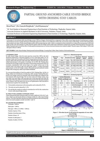
ABSTRACT As the span of conventional cable stayed bridge crosses 1000 m or longer, a horizontal force component of stay cables causes large amount of axial pressure in girder, which leads an increase of girder dimension and height respectively. Hence it is too difficult to follow the cost economy aspect of the bridge. In 2014, Mr Xudong Shao has invented a new type of cable stayed bridge system with crossing long stay cable, which is considered as the economical as it reduces the axial pressure in the steel girder. In this work, My attempt is to study steel box girder of the new bridge system under load combination of dead load, secondary dead load and moving load as per Indian Standards and to check the effect of reducing horizontal pressure on various structural elements also studied in depth. The given span of the bridge is 1408 m and side span is about 2 x 600 m. KEY WORDS: Cable-Stayed bridge, Partial ground Anchored Bridge, Crossing Stay Cables, Static Analysis, Horizontal pressure. I. INTRODUCTION In cable stayed bridge, when the main span has crossed the 1000 m the deck should be preferred by a structural engineer is to be a steel deck girder. So, my attempt is study steel box girder with Partial Ground anchored bridge with crossing stay cable in the mid zone of the main span. When the span increases the horizontal axial pressure in the girder is increased. So In 2014, Mr. Xudong shao introduced a new bridge system in the aspect of horizontal axial pressure and cost economic consideration with various types of six girder section uses in the research. But I am trying to take one steel girder section to reduce horizontal axial pressure in the new bridge system with partial ground anchored system bridge with crossing stay cables as per Indian Standards. To overcome the problem of steel box girder in 2014, Xudong Shao, Jai Hu, Lu Deng, Junhui Cao introduced a crossing stay cable concept. Xudong Shao proposed a new bridge system for long span cable stayed bridge and compared with conventional cable stayed bridge. He was done in the new bridge system, long stay cable cross each other in the mid span zone of the main span and while the other ends of the long cables are anchored to the ground in the side span designed as per Chinese Code. His main focus was on cost optimization with a decrease in axial pressure in girder. He concludes that, 1) Horizontally axial pressure in the main girder can be reduced by 29.6%. 2) The total cost can be reduced by 11.8%. 3) He said that the cantilever method is introduced as well for the construction for new cable stayed bridge system. II. STRUCTURAL MODEL CONFIGRUATION A three dimensional finite element model was ready in MIDAS CIVIL 2017 software, which is an advanced software of design in India for cable stayed bridge analysis. The following table indicates the material properties and sectional properties were used to prepare a model: (see table: 1 and 2)
Table No 1: Material properties Material Name Girder Pylon Pylon-1 Cable Pylon Cross beam Auxiliary Piers
Elasticity Poisson Density (kN/m2) Ratio (kN/m3) 0.3 7.698e+001 2.025e+08 3.535e+007 0.2 2.50e+001 3.535e+007 0.2 2.340e+001 2.050e+008 0.3 7.688e+001
Type
Standard Grade
Steel Concrete Concrete Steel
IS(S) Fe 370 IS(RC) M 50 IS(RC) M 50 IS(S) Fe 540
Concrete
IS(RC)
M 50 3.535e+007
0.2
2.50e+001
Concrete
IS(RC)
M 50 3.535e+007
0.2
2.50e+001
Table No 2 : Sectional properties Section Name Girder Pylon Pylon-1 Cable Pylon Cross Beam Auxiliary Piers
Section Dimension Width (m) Height (m) 40 6(0.5) 6
4 6(0.5) 6 0.41
Type
Area (m2) Izz (m4)
45.75 5.43e+03 Steel Box 107.91 Hollow Rectangular 35 Solid Rectangular 36 108 Solid circular 1.25e-01 1.25e-03
5
5
Solid Rectangular
25
52.08
5
5
Solid Rectangular
25
52.08
III. GEOMETRY OF BRIDGE Total span = 2608 m. Main span = 1408 m. Side span = 600 m. (2 x 600m = 1200 m). Number of pylon: 4 Nos. Number of auxiliary piers: 8 Nos.
Figure 1 : Elevation layout of self-anchored suspension of cross cable stayed bridge
Number of lanes: 10 Number of cable plane: 2 Number of cables: 432 Nos.
Figure 2: Dimension of steel box girder CopyrightŠ 2016, IERJ. This open-access article is published under the terms of the Creative Commons Attribution-NonCommercial 4.0 International License which permits Share (copy and redistribute the material in any medium or format) and Adapt (remix, transform, and build upon the material) under the Attribution-NonCommercial terms.
International Education & Research Journal [IERJ]
220
Research Paper
E-ISSN No : 2454-9916 | Volume : 3 | Issue : 5 | May 2017
The following condition and assumptions are used in the modeling process: 1.
The moving load used as per IRC 6 : 2014 Section: II LOADS AND STRESSES specifications Class AA Loading.
Maximum allowable stress, = 0.50 x Fy = 0.50 x 370 = 185 N / mm2
2.
The Secondary Dead load is 62.5 kN/m.
3.
The Yield Stress of cable is 1860Mpa.
4.
The Girder Steel grade is Fe370 with design allowable stress is 185Mpa.
5.
The pylon and auxiliary pier concrete grade are M50.
At pylon, 65 Mpa < 185 Mpa = O.K
The Multi-cell steel box girder bridge is shown in figure-2 the girder depth is 4m and schematic diagram and detailed summary shown in figure-2. The pylon shape is H-type with cable arrangement system is fan system. The cables are high strength parallel strength with yield stress 1860Mpa. IV. STATIC ANALYSIS Static analysis is done through MIDAS CIVIL 2017 Software under load combination of dead load and moving load shown in the Table-3. Table No 3 : Load Combination Load Dead load
Value Calculate by software.
Secondary Dead load Moving load
62.5 kN/m. Class A + Class AA loading
IV(I). STATIC EFFECTS IN BRIDGE COMPLETION STAGE Figure-3 Shows axial force in girder. The origin of the horizontal axis is the same as the x-axis in figure –1.
Figure 4 : Axial stress of girder under effect of dead load + secondary dead load + moving load Figure-4 is indicated that the maximum girder compressive stress at the pylon 65Mpa and in the cross cable system girder tensile stress is 16Mpa And girder tensile stress is less at near the abutment 6Mpa.
Girder Axial Force: For Fe-370 grade steel,
Girder bending Moment:
Maximum allowable stress, = 0.50 x Fy = 0.50 x 370 = 185 N / mm2 First, Stress in N / mm2 converted into kN/m2 = 18500 kN / m2 Second, Stress converted into force Girder Stress = Girder Force = Girder stress x area = 18500 x 45.75 = 8.46e+06 kN At near to Pylon in the side span, The Girder force = -2.89e+06 kN
Figure 5: Girder bending moment of girder under effect of dead load + secondary dead load + moving load
2.89e+06 < 8.46e+06 kN. Figure-5 is indicated that the maximum bending moment at the pylon 1.45e+07 kN.m and in the cross cable system girder bending moment is 2.78e+05 kN.m
= O.Ks
Cable Stress:
Figure 3 : Axial force of girder under effect of dead load and secondary dead load Figure-3 is indicated that the maximum girder axial force is more at the pylon 1.32e+06kN (compressive force) and at the abutment and cross cable system 3.05e+05kN and 7.06+05kN (tensile force)respectively due to partial ground anchored system. Girder Stress:
Fig 6: Cable Stress under Dead load + Secondary dead load + moving load Figure-6 is indicated that the cable stress in N/mm 2 for individual cable profile and it is indicated that cable stress is maximum in and near to support long stay cable (738Mpa ) and but in the limit under dead load + secondary dead load + live load. The allowable stress under dead load + secondary dead load + live load is 744 N/mm2(AASHTO-LRFD).
For, Fe-370 grade steel,
221
International Education & Research Journal [IERJ]
Research Paper
E-ISSN No : 2454-9916 | Volume : 3 | Issue : 5 | May 2017
IV(II). EFFECTS IN OPERATION STAGE Under the combined effect of dead load and secondary dead load maximum girder axial force at pylon is 2.36e+06 and the maximum axial stress is also at pylon is 65Mpa. The maximum bending moment under a combination of dead load and moving load occurs at pylon is 1.45e+07kN.m and in cross cable system the maximum bending moment occurs in the mid span is 2.78e+05kN. m. The Girder displacement under dead load is 0.523 m is in control as per the criteria of IRC specifications (L/500=2.82m) in the longitudinal direction and due to moving loads girder displacement is 0.235 m in the traverse direction (L/1000=1.4m). Under the combined effect of dead load and moving load the Maximum compressive stress of pylon is 29Mpa and the cross beam at the pylon near cable system compressive stress is 13Mpa. The cross beam under girder maximum compressive stress is 10MPa. . Under the combined effect of dead load and moving load the maximum stress of cable is 732MPa, smaller than the allowable stress of cable 744MPa. V. EIGEN VALUE ANALYSIS
Figure 7 : (a) lateral symmetric bending of girder (b) symmetric torsion of girder (c) Longitudinal floating of girder VI. CONCLUSION The complete work technically highlights the reduction of horizontal pressure around 70% of the total allowable pressure. The effect of reducing horizontal pressure on various structural elements also studied in depth which shows the values in displacement, bending moment and cable stress is within IRC pre-scribed limits under the load combination. The cross stay cable system can be effectively for long span cable stayed bridge system. VII. FUTURE WORK Further research is needed in the following aspect of crossing cable stayed bridge. 1.
Non-linear effects
2.
Performance under wind
3.
Earthquake loading
VIII. REFERENCES [1] AASHTO-LRFD specifications 7th Edition - 2016 [2] IRC 6 : 2014 Section-II LOADS AND STRESSESS [3] Xudong Shao, Jia Hu, Lu Deng, Junhui Cao (2014), “Conceptual Design of Superspan Partial Ground-Anchored Cable-stayed Bridge with Crossing Stay Cables”, Department of Bridge Engineering, Hunan University, Changasha, Hunan, China.(ASCEJournal of bridge engineering). [4] Yutaka Okamoto, Shunichi Nakamura (2011),“Static And Seismic Studies on Steel / Concrete Hybrid Towers for multi-span Cable-stayed Bridge”, Civil Engineering Course, Graduate School of Engineering, Tokai University, Hiratsuka, Japan. (Science direct-(ELSEVIER)-Journal of construction steel research)
International Education & Research Journal [IERJ]
222