Engineering
Research Paper
E-ISSN No : 2454-9916 | Volume : 3 | Issue : 6 | June 2017
INTELLIGENT CONTROL OF IRRIGATION PUMPSETS USING RAINSENSOR 1
Mrs. Prarthana J V | Mrs. Deepthi H L 1
1
Asst. Professor, Dept of EEE, SJBIT, Bengaluru, Karnataka, India.
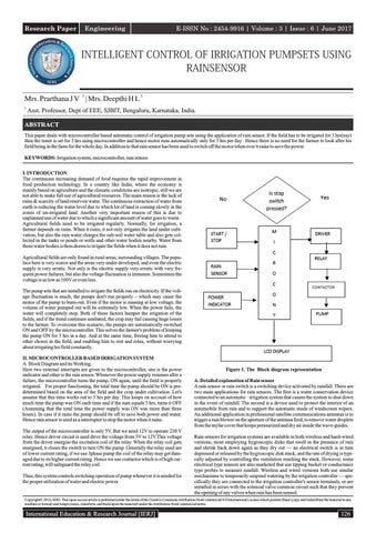
ABSTRACT This paper deals with microcontroller based automatic control of irrigation pump sets using the application of rain sensor. If the field has to be irrigated for 3 hrs(say) then the timer is set for 3 hrs using microcontroller and hence motor runs automatically only for 3 hrs per day . Hence there is no need for the farmer to look after his field being in the farm for the whole day. In addition to that rain sensor has been used to switch off the motor when ever it rains to save the power. KEYWORDS: Irrigation system, microcontroller, rain sensor. I. INTRODUCTION The continuous increasing demand of food requires the rapid improvement in food production technology. In a country like India, where the economy is mainly based on agriculture and the climatic conditions are isotropic, still we are not able to make full use of agricultural resources. The main reason is the lack of rains & scarcity of land reservoir water. The continuous extraction of water from earth is reducing the water level due to which lot of land is coming slowly in the zones of un-irrigated land. Another very important reason of this is due to unplanned use of water due to which a significant amount of water goes to waste. Agricultural fields need to be irrigated regularly. Normally, for irrigation, a farmer depends on rains. When it rains, it not only irrigates the land under cultivation, but also the rain water charges the sub-soil water table and also gets collected in the tanks or ponds or wells and other water bodies nearby. Water from these water bodies is then drawn to irrigate the fields when it does not rain. Agricultural fields are only found in rural areas, surrounding villages. The populace here is very scarce and the areas very under developed, and even the electric supply is very erratic. Not only is the electric supply very erratic with very frequent power failures, but also the voltage fluctuation is immense. Sometimes the voltage is as low as 100V or even less. The pump sets that are installed to irrigate the fields run on electricity. If the voltage fluctuation is much, the pumps don't run properly – which may cause the motor of the pump to burn-out. Even if the motor is running at low voltage, the volume of water pumped out will be extremely low. When the power fails, the water will completely stop. Both of these factors hamper the irrigation of the fields, and if the trend continues unabated, the crop may fail causing huge losses to the farmer. To overcome this scenario, the pumps are automatically switched ON and OFF by the microcontroller. This solves the farmer's problem of keeping the pump ON for 3 hrs in a day. And at the same time, freeing him to attend to other chores in the field, and enabling him to rest and relax, without worrying about irrigating his field constantly. II. MICROCONTROLLER BASED IRRIGATION SYSTEM A. Block Diagram and its Working. Here two external interrupts are given to the microcontroller, one is the power indicator and other is the rain sensor. Whenever the power supply resumes after a failure, the microcontroller turns the pump, ON again, until the field is properly irrigated. For proper functioning, the total time the pump should be ON is predetermined based on the area of the field and the crop under cultivation. Let's assume that this time works out to 3 hrs per day. This keeps on account of how much time the pump was ON each time and if the sum equals 3 hrs, turns it OFF (Assuming that the total time the power supply was ON was more than three hours). In case if it rains the pump should be off to save both power and water. Hence rain sensor is used as a interrupter to stop the motor when it rains. The output of the microcontroller is only 5V. But we need 12V to operate 230 V relay. Hence driver circuit is used drive the voltage from 5V to 12V.This voltage from the driver energise the excitation coil of the relay. When the relay coil gets energised, it closes the switch to turn ON the pump. Generally the relay used are of lower current rating, if we use 3phase pump the coil of the relay may get damaged due to its higher current rating. Hence we use contactor which is of high current rating, will safeguard the relay coil. Thus, this system controls switching operation of pump whenever it is needed for the proper utilization of water and electric power.
Figure 1. The Block diagram representation A. Detailed explanation of Rain sensor A rain sensor or rain switch is a switching device activated by rainfall. There are two main applications for rain sensors. The first is a water conservation device connected to an automatic irrigation system that causes the system to shut down in the event of rainfall. The second is a device used to protect the interior of an automobile from rain and to support the automatic mode of windscreen wipers. An additional application in professional satellite communications antennas is to trigger a rain blower on the aperture of the antenna feed, to remove water droplets from the mylar cover that keeps pressurized and dry air inside the wave-guides. Rain sensors for irrigation systems are available in both wireless and hard-wired versions, most employing hygroscopic disks that swell in the presence of rain and shrink back down again as they dry out — an electrical switch is in turn depressed or released by the hygroscopic disk stack, and the rate of drying is typically adjusted by controlling the ventilation reaching the stack. However, some electrical type sensors are also marketed that use tipping bucket or conductance type probes to measure rainfall. Wireless and wired versions both use similar mechanisms to temporarily suspend watering by the irrigation controller — specifically they are connected to the irrigation controller's sensor terminals, or are installed in series with the solenoid valve common circuit such that they prevent the opening of any valves when rain has been sensed.
Copyright© 2016, IERJ. This open-access article is published under the terms of the Creative Commons Attribution-NonCommercial 4.0 International License which permits Share (copy and redistribute the material in any medium or format) and Adapt (remix, transform, and build upon the material) under the Attribution-NonCommercial terms.
International Education & Research Journal [IERJ]
126
Research Paper
E-ISSN No : 2454-9916 | Volume : 3 | Issue : 6 | June 2017 When the Start/Stop switch is pressed, a '0' signal is received on line P0.1 , In response to this, the µC sends a '1' signal on line P1.0 which turns the motor ON. Once the motor is turned ON, a timer starts to decrement to 'time' the motor's 'ON' duration. If the power does not fail, the timer ultimately decrements to zero and the motor is turned OFF by sending a '0' signal on line P1.0 If the power fails when the motor is ON, the µC receives a '0' signal on line P0.0 – in response to this, the µC freezes the timer, and it does not decrement until the power is restored. If it starts raining when the motor is ON, the µC receives a '1' signal on line P0.2, in response to this the µC turns the motor OFF, by sending a '0' signal on line P1.0 and it continues to decrement the timer – if the timer becomes zero, the set time is out. Or if it stops raining before the timer becomes zero, the motor is turned 'ON' once again till the timer becomes zero.
Figure 2. Rain sensor circuit diagram III CIRCUIT DIAGRAM AND EXPLANATION Irrigation pump sets normally use 3-phase induction motors. These Induction motors use a starter which also has a contactor. The contactor ultimately switches ON or OFF the power to the 3-phase induction motor which drives the centrifugal pump. In this circuit, the starter is replaced by a DC relay. This relay operates on 12V DC supply. It has a contact rating of 230V AC / 5A. This power rating is sufficient to drive the relay coil of the contactor. This relay is controlled by a port line of the micro- controller. The port lines of the microcontroller can normally drive only TTL loads and not a 12V relay coil. To achieve this, a transistor is used as a switch to turn ON or OFF the relay coil operating at 12V DC. The port line P1.0 of Port 1 controls the relay coil which in turn controls the contactor, which ultimately controls the 3-phase induction motor. When the port line P1.0 outputs a 'high' signal i.e., a logical '1', the base of the transistor is driven by a current Ib through the resistor Rb. This drives the transistor into the saturation region and causes a current Ic which equals (β x Ib) to flow through the relay coil, causing it to operate. When P1.0 outputs a 'low' signal (logical '0') the Ib = 0 hence Ic is also zero, therefore no current flows through the relay – since the transistor is in the cut-off region. This does not operate the relay hence the contactor does not operate, and the 3-phase motor attached to it does not work.
The micro-controller used in this project is AT89C51 from ATMEL. This microcontroller has 128 bytes of RAM and 4k Bytes of Flash EPROM. It has 32 programmable I/O lines, two 16-Bit Timers/Counters, six Interrupt sources and Programmable Serial I/O Channels. Apart from the port lines used for I/O as mentioned, a few more I/O lines are used for interfacing an LCD Display to it. They are as follows: All 8 lines of Port3: P3.0 – P3.7 are used to connect to the data lines of the LCD Module. P1.5 is connected to the RS/DE' line of the LCD. P1.6 is connected to the R/W' line of the LCD. P1.7 is connected to the E line of the LCD. +5V Vcc is applied to pin 40 of 89C51 and pin 2 of the LCD. 0V (GND) is applied to pin 20 of 89C51 and pin 1 of the LCD. Pin 3 of the LCD is driven by a potential divider for controlling the contrast of the LCD. Pins 15 & 16 of the LCD are connected to +5V & GND respectively – to turnON the LEDs for back-lighting the LCD panel. A crystal is connected across pins 18 & 19 of 89C51; this crystal drives the internal clock generator, which generates square wave pulses at 11.0592MHz. V. CONCLUSION The combination of hardware and software provides an irrigation controller that can be implemented at relatively low cost and which is extremely user friendly. This solves the farmer's problem of keeping the pump ON for specified hours in a day. And at the same time, freeing him to attend to other chores in the field, and enabling him to rest and relax, without worrying about irrigating his field constantly. REFERENCES [1] Abhinav Rajpal, Sumit Jain, Nistha Khare and Anil Kumar Shukla, “Microcontrollerbased Automatic Irrigation System with Moisture Sensors”, Amity Institute of Telecom Technology & Management, Amity University, U.P. Sector-125, Noida-201303. [2] Ahmed, V. , “ Innovative cost effective approach from cell phone based remote controlled embedded system for irrigation”, International Conference on Communication Systems and Network Technologies, 2011, pp. 419-144, 2011 [3] Muhammad Ali Mazidi and Janice Gillispe Mazidi, “The 8051microcontroller and embedded systems”, Pearson education ltd., India, 2007
Figure 3. The Circuit diagram The port line P0.0 is an active high input line. It receives a high signal from the 'Power Good' circuit if there is power and a low signal if the power fails. The port line P0.1 is an active low input line. It receives a low signal to start or stop from a toggle switch. The first low signal is to start and the next low signal is to stop, and the next is start and so on. The port line P0.2 is an active high input line. It receives a high signal from the rain sensor if it is raining. Or else, it receives a low signal.
127
International Education & Research Journal [IERJ]