Research Paper
Engineering
E-ISSN No : 2454-9916 | Volume : 3 | Issue : 7 | July 2017
TRANSFORMER HEALTH MONITORING SYSTEM
1
Keerthan Reddy G K | Abdul Razak H S 1
1
Final year students, Department of Electrical and Electronics, Sapthagiri College of Engineering, Bengaluru.
ABSTRACT Power transformer is a complex and critical component of the power transmission and distribution system. System abnormalities, loading, switching and ambient condition normally contributes towards accelerated aging and sudden failure. In the absence of critical components monitoring, the failure risk is always high. For early fault detection and real-time condition assessment, online monitoring system in accordance with age and conditions of the asset would be an important tool. After being indicative of abnormality, it is important to carry out offline tests/ diagnostics to ascertain the overall integrity and assessment to avoid unscheduled outages, financial/ revenue losses and environmental/ collateral damages. Paying higher attention to vital equipment Transformers are valuable components in electrical power networks Outages have not only financial repercussions, they also impact on the stability of the grid. KEYWORDS: Power transformer, health of transformer, grid stability, economic losses, Raman spectroscopy. INTRODUCTION: Transformers as we know are the most important and integral part of the power system, the failure of which will result in blackout of the consumers connected to it in case of a small distribution transformer. If the fault occurs in power transformers then the entire city will experience the blackout and the stability of the grid will be affected severely, in-order to overcome this a warning of the impending failure well in advance is necessary, which can be done by continuously monitoring the health of the transformer. With over 50% of the transformers in India being older than 15 years the probability of them failing is high. With an impending threat care should be taken as to know when a transformer will fail or when is the time to service a transformer without allowing any unwanted damages that can occur to the entire grid. Not just that the failures of transformers will also result in economic losses to the company that manufactures them, the utility company that is using them and to the consumers connected to the grid. With more than 20 causes for the failure we had concentrated on the main 10 failures that are comparatively easier to tap and process the data that we obtain. On conducting further research on the topic, we concluded that we can understand the inside changes that the transformer is undergoing by employing just 3 systems. This system not only work for the newly designed transformers but can be employed in the already existing transformers too. The main analysis that we are trying to do is solely on 3 parameters they are being 1.
Dissolved molecules analysis
2.
Temperature of the windings and the contact points
3.
Transformer tank mapping.
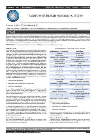
Table 1: Failures and parameters to measure to know it PARAMETERS TO MEASURE
FAILURES
Hot spots
inter-turn faults
Oil temperature
Oil breakdown
Moisture in oil & Insulating paper
Oil contamination
Winding temperature
Improper cooling & short circuit
Humming noise
Magnetic core faults Ageing
Pressure inside tank
internal fault situation or under excess load
Sludging
Ventilation failure
Acidity in oil
Oil contamination & chemical reaction
Gases evolved
Short circuit & oil contamination
Oil leakage
Improper maintenance
Current in the winding
Short circuit
Terminal voltage
Over loading
Over heating
Burnt contact in tapings (Tap switch)
Maloperation, Failure of operating Inoperative Broken Lever (Tap switch) mechanism
We know that by testing the blood of a human being we can find out most of the diseases or the organ failures that the person is undergoing. Oil being considered as the blood of the transformer can give out a significant amount of data if not all about the health of the transformer. It is a well-known fact that as the current passes through a conductor it produces heat which is nothing but infrared radiations which isn't visible to human eye but can be felt. When there exists a turn to turn fault between the windings within a transformer this heat energy associated with the flow of current through a conductor increases exactly at the point of fault due to short circuit a system which can detect this point accurately can help us stop the fault from further progress.
Cellose content in oil
B.D. V
Oil contamination
Acidity in oil
Oil Decomposition (Rancidity)
Excessive Internal pressure
Tank deformation
Over heating
Improper circulation of cooling oil &/ inadequate ventilation (Failure in radiator)
Inlet chocked & silica gel saturated
Breather failure
The parameters that we consider are : 1. Online dissolved molecules analysis 2.
Temperature of the windings and the contact points
3.
Transformer tank mapping.
Oil which is very much necessary in the distribution and power transformers to carry out the heat generated might be leaking over through a small hole in the core structure which might go unnoticed over a long period of time. To know if there is a breach in the core structure which can be a small hole a loose bushing a system is required which maps the entire area after a specific interval of time if not continuously so that the problem is solved well before the oil drains out of the transformer in an alarming rate.
Among the above-mentioned parameters, we are concentrating on the online dissolved molecule analysis in this paper as they can give out more details about the system than the other two.
Faults and the parameters to study to know them: With over 20 faults associated with the transformers that can result in a transformer failure we need to consider only 3 among them to for us to able to predict the life of the transformers well in advance.
Online dissolved molecules analysis: When there is a fault inside a transformer irrespective of it being the inter turn fault, oil contamination or the insulation of the windings being subjected to ageing can be found out using a dissolved molecule analysis.
CopyrightŠ 2016, IERJ. This open-access article is published under the terms of the Creative Commons Attribution-NonCommercial 4.0 International License which permits Share (copy and redistribute the material in any medium or format) and Adapt (remix, transform, and build upon the material) under the Attribution-NonCommercial terms.
International Education & Research Journal [IERJ]
67
Research Paper
E-ISSN No : 2454-9916 | Volume : 3 | Issue : 7 | July 2017
INTER TURN FAULT : If there is an inter turn fault it would result in decomposition of oil surrounding it and various gases are evolved depending upon the severity of the fault. The various gases evolved are H2, CO, CO2, C2H2, C2H4, CH4, C2H6. These gas molecules dissolve into the oil forming a mixture of oil and gas which is termed as dissolved gas. These dissolved gases if monitored regularly will help us prevent the failure of the transformer. In the present age, the transformer oil is tested for every 6 months for power transformers of higher rating and once in a year or two for power transformers of lower ratings, which most of the time will also be neglected while the distribution transformers are completely neglected. The present technology used is gas chromatography. This requires a personal to physically collect the oil from the transformer tank send it to the labs where the gases will be separated from the gas and analysed and reports being sent back. This process which is carried out irregularly is an accurate one but the time interwar between which this test is done is long and a transformer can fail in that time period or it could have gone into a unrepairable stage thus forcing the utility companies to change the transformers all together or pay an hefty price for the repair work.
The variation in frequency Δν of the Raman scattering is called Raman shift, which corresponds to fundamental frequency of a vibrational mode of the molecule, giving out the information of the molecules. When the incident light is constant, the peak intensity of the Raman spectra generated by the gas is proportional to the gas concentration. Based on this principle, by analysing the Raman shift and peak intensity, we can get the content and the concentration of the sample gas without separating the mixed gas, which is convenient to achieve in the qualitative and quantitative analysis for dissolved gases in oil. A. THE SELECTION FOR CHARACTERISTIC SPECTRAL LINES: Polyatomic molecules may have various vibration modes, corresponding to their respective Raman frequency shift spectral lines with different intensities. Thus, the Raman characteristic spectral lines of the fault characteristic gases must be selected before analysis. Through the B3LYP method and 6-31G* basis set in Gaussian 09W program, we obtain the calculated Raman spectra of the fault characteristic gases (CO, CO2, C2H2, C2H4, CH4, H2, C2H6). After multiplied by the correction factor, the calculated Raman spectra can match well with the measured Raman spectra of a mixed gas sample containing the seven gases.
AGEING OF TRANSFORMER As the transformer ages, the insulation provided to the windings also ages and a part of the insulation would have either decomposed owing to the various chemical process that occurs between the oil and insulation and between the dissolved gas or water and insulation. Fewer times the insulation paper would have been subjected to mechanical forces resulting in tampering of the same due to friction between different windings. This decomposed molecule or weathered out molecules of the insulation paper will mix up with the oil contaminating it and changing its chemistry. If this problem is not identified well in advance and rectified there will be two different failures that the transformer might undergo namely the inter turn fault because and oil contamination which will change its chemistry thus affecting the main cooling medium of the transformer.
Figure 3: measured Raman spectrum for methane in oil
Figure 1: Leakage fields and mechanical forces in conductors All these failures (inter turn fault & ageing) inside a transformer can be found using the online dissolved molecule analysis. The procedure followed for the dissolved molecule analysis is the Raman spectroscopy.
EXPERIMENTAL SETUP: The overall structure of the gas Raman scattering detection system is shown in Fig. 4. The system is equipped with a laser. Initially the oil of around 5ml is pumped out of the transformer using a motor and the sample is fed into a quartz tube, this has been depicted in the figure 4.A. The quartz tube is placed inside a system which can detect the Raman scattering. For our study purpose, we injected the sample manually into the quartz tube and proceeded with our experimentation. For our experimental work, we mixed a fresh oil with methane thus simulating a faulty condition of the transformer winding.
Raman spectroscopy to detect dissolved molecules: PRINCIPLE OF RAMAN SPECTROSCOPY The principle of Raman scattering is shown in Fig. 2. The electrons in gas molecule absorb the photons of incident light with the energy of hν0 and then jump from the ground state to a virtual state. The virtual state is not a stable energy state, so a part of the electrons returns to the ground state and release the photons with the energy of hν0, which is the Rayleigh scattering light without frequency change. Another part of the electrons returns to the vibrational excited state and release the photons with the energy of h(ν0-Δν), which is the Raman scattering light (Stokes line) with the frequency change.
Figure 4 : (A) Overall Desgin Scheme
Figure 2: Schematic diagram of Raman scattering process
68
International Education & Research Journal [IERJ]
Research Paper
E-ISSN No : 2454-9916 | Volume : 3 | Issue : 7 | July 2017 REFERENCES: 1. Lizhi Zhao, Weigen Chen, Fu Wan, Jing Shi “Laser Raman Spectroscopy Applied in Detecting Gas in Transformer Oil”, 2013 Annual Report- Conference on Electrical Insulation and Dielectric Phenomena 2.
X.G. Yang, Q.L. Wu, Raman spectroscopy analysis and application. Beijing: National Defence Industry Press, 2008.
3.
DR.G.V.RAO “ROWSONS TRANSFORMER MANUAL”
Figure 4: Figure representing overall experimental arrangement Once the sample is obtained we can do the analysis as follows. The process of estimating the methane concentration is as follows, we first pass a monochromatic light through the diaphragm and then pass it through a clean pass filter which will be aligned in the same line. Further this light is passed through the sample where the methane molecules vibrate and give out their finger prints in the form of Raman scattering. This scattered light is then filtered using an edge filter and is directed to the grating through which we obtain the Raman spectrum of the sample. The results obtained were found out to have a lot of disturbance in them which couldn't have been used for a scientific analysis. To minimize the disturbance in the obtained spectrum we went ahead with a silver-plated quartz tube as suggested by the authors of the paper “Laser Raman Spectroscopy Applied in Detecting Gas in Transformer Oil”. By employing the method suggested we were able to obtain a satisfactory amount of precision.
Figure 5: Enhancement principle of silver plated quartz tube gas sample cell, (a) is the signals excitation process, and (b) is the signals collection process. The Raman spectroscopy is can be employed in transformers which can analyse the oil sample for every 4 hours or whenever the need arises without having to physically collect the oil sample and sending the sample to the lab for the further tests. The Raman spectroscopy is also a time tested and accurate method to test the presence of molecules in the sample as it tracks down each molecule present in the sample. CONCLUSIONS 1. We can pick out the Raman characteristic spectra of the dissolved gases in transformer oil, and obtain the qualitative and quantitative analysis methods of the seven fault characteristic gases. 2.
We can build a laser Raman spectroscopy test platform which can effectively detect the mixed gas. Thus, the application of Raman scattering in DGA is feasible.
3.
The detection sensitivity of the test platform achieves 5μL/L to C2H2, which can be increased further through enhancing laser power, strengthening gas pressure, and improving the structure of the gas cell.
International Education & Research Journal [IERJ]
69