Research Paper
Engineering
E-ISSN No : 2454-9916 | Volume : 3 | Issue : 10 | Oct 2017
COST COMPARISON OF CONVENIENT FRAME WITH SHEAR WALL-FLAT SLAB SYSTEM Asodariya Ankit 1 | Chirag Odedara 2 1 2
M.Tech Student in Structural Engineering in Parul Institute of Technology, Waghodia, Gujarat, India. Assistant Professor in Civil Engineering Department in Parul Institute of Technology, Waghodia, Gujarat, India.
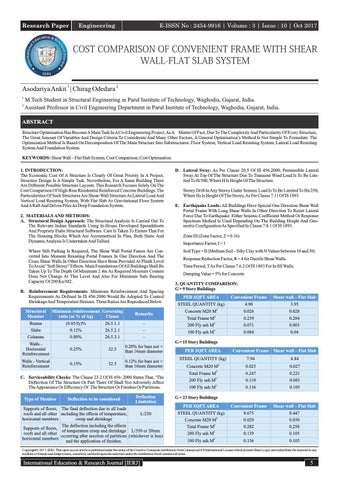
ABSTRACT Structure Optimisation Has Become A Main Task In A Civil Engineering Project. As A Matter Of Fact, Due To The Complexity And Particularity Of Every Structure, The Great Amount Of Variables And Design Criteria To Considerate And Many Other Factors, A General Optimisation’s Method Is Not Simple To Formulate. The Optimization Method Is Based On Decomposition Of The Main Structure Into Substructures: Floor System, Vertical Load Resisting System, Lateral Load Resisting System And Foundation System. KEYWORDS: Shear Wall – Flat Slab System, Cost Comparison, Cost Optimsation. 1. INTRODUCTION: The Economic Cost Of A Structure Is Clearly Of Great Priority In A Project, Structure Design Is A Simple Task. Nevertheless, For A Same Building There Are Different Possible Structure Layouts. This Research Focuses Solely On The Cost Comparison Of High-Rise Residential Reinforced Concrete Buildings. The Particularities Of Such Structures Are Shear-Wall Structure As Lateral Load And Vertical Load Resisting System, With Flat Slab As Gravitational Floor System And A Raft And Driven Piles As Deep Foundation System. 2. MATERIALS AND METHODS: A. Structural Design Approach: The Structural Analysis Is Carried Out To The Relevant Indian Standards Using In-House Developed Spreadsheets And Propriety Etabs Structural Software. Care Is Taken To Ensure That For The Housing Blocks Which Are Asymmetrical In Plan, Both Static And Dynamic Analysis Is Undertaken And Tallied. Where Stilt Parking Is Required, The Shear Wall Portal Fames Are Converted Into Moment Resisting Portal Frames In One Direction And The Cross Shear Walls In Other Direction Have Been Provided At Plinth Level To Avoid “Soft Storey” Effects. Main Foundations Of All Buildings Shall Be Taken Up To The Depth Of Minimum 2.4m As Required Moisture Content Does Not Change At This Level And Also For Minimum Safe Bearing Capacity Of 200 Kn/M2. B. Reinforcement Requirements: Minimum Reinforcement And Spacing Requirements As Defined In IS 456:2000 Would Be Adopted To Control Shrinkage And Temperature Stresses. These Ratios Are Reproduced Below Structural Member
Minimum reinforcement Governing ratio (as % of Ag) Clause
Beams Slabs
Remarks
(0.85/fy)% 0.12% 0.80%
26.5.1.1 26.5.2.1
-
26.5.3.1
-
Walls Horizontal Reinforcement
0.25%
32.5
0.20% for bars not > than 16mm diameter
Walls - Vertical Reinforcement
0.15%
32.5
0.12% for bars not > than 16mm diameter
Columns
Storey Drift In Any Storey Under Seismic Load Is To Be Limited To Hs/250, Where Hs Is Height Of The Storey, As Per Clause 7.11 Of IS 1893. E. Earthquake Loads: All Buildings Have Special One Direction Shear Wall Portal Frame With Long Shear Walls In Other Direction To Resist Lateral Force Due To Earthquake. Either Seismic Coefficient Method Or Response Spectrum Method Is Used Depending On The Building Height And Geometric Configuration As Specified In Clause 7.8.1 Of IS 1893. Zone III (Zone Factor, Z = 0.16) Importance Factor, I = 1 Soil Type = II (Medium Soil – Silty Clay with N Values between 10 and 30) Response Reduction Factor, R = 4 for Ductile Shear Walls. Time Period, T As Per Clause 7.6.2 Of IS 1893 For In fill Walls. Damping Value = 5% for Concrete 3. QUANTITY COMPARISON: G + 9 Story Buildings PER SQFT AREA
Convenient Frame
STEEL QUANTITY (kg)
4.90
Shear wall – Flat Slab 3.95
Concrete M20 M2
0.026
0.028
Total Frame M2
0.259
0.204
200 Fly ash M2 100 Fly ash M2
0.071 0.084
0.065 0.04
G + 15 Story Buildings
C. Serviceability Checks: The Clause 23.2 Of IS 456: 2000 States That, ‘The Deflection Of The Structure Or Part There Of Shall Not Adversely Affect The Appearance Or Efficiency Of The Structure Or Finishes Or Partitions. Type of Member
D. Lateral Sway: As Per Clause 20.5 Of IS 456:2000, Permissible Lateral Sway At Top Of The Structure Due To Transient Wind Load Is To Be Limited To H/500, Where H Is Height Of The Structure.
Deflection to be considered
Deflection Limitation
Supports of floors, The final deflection due to all loads roofs and all other including the effects of temperature, horizontal members creep and shrinkage
L/250
The deflection including the effects Supports of floors, of temperature creep and shrinkage L/350 or 20mm roofs and all other occurring after erection of partitions (whichever is less) horizontal members and the application of finishes.
PER SQFT AREA
Convenient Frame Shear wall – Flat Slab
STEEL QUANTITY (kg)
7.94
6.84
Concrete M20 M2
0.025
0.027
Total Frame M2
0.247
0.221
200 Fly ash M2
0.110
0.083
100 Fly ash M2
0.136
0.105
G + 23 Story Buildings PER SQFT AREA
Convenient Frame
Shear wall – Flat Slab
STEEL QUANTITY (kg) Concrete M20 M2
9.675 0.029
8.447 0.030
Total Frame M2 200 Fly ash M2
0.282 0.139
0.258 0.105
100 Fly ash M2
0.136
0.105
Copyright© 2017, IERJ. This open-access article is published under the terms of the Creative Commons Attribution-NonCommercial 4.0 International License which permits Share (copy and redistribute the material in any medium or format) and Adapt (remix, transform, and build upon the material) under the Attribution-NonCommercial terms.
International Education & Research Journal [IERJ]
5