ANSI/PHTA/ICC-4 2025 American National Standard for Aboveground/Onground Residential Swimming Pools
ANSI/PHTA/ICC-4 2025 American National Standard for Aboveground/Onground Residential Swimming Pools
Approved February 20, 2025
1650 King St., Ste. 602 Alexandria, VA 22314
703-838-0083 phta.org Approved February 20,
American National Standard
Approval of an American National Standard requires verification by the American National Standards Institute (ANSI) that the requirements for due process, consensus, and other criteria for approval have been met by the standard developer. Consensus is established when, in the judgment of the ANSI Board of Standards Review, substantial agreement has been reached by directly and materially affected interests. Substantial agreement means much more than a simple majority, but not necessarily unanimity.
Consensus requires that all views and objections be considered and that a concerted effort be made toward their resolution. The use of American National Standards is completely voluntary; their existence does not in any respect preclude anyone, whether they have approved this standard or not, from manufacturing, marketing, purchasing, or using products, processes, or procedures not conforming to the standards.
The American National Standards Institute does not develop standards and will in no circumstances give an interpretation of any American National Standard. Moreover, no person shall have the right or authority to issue an interpretation of an American National Standard in the name of the American National Standards Institute. Requests for interpretations should be addressed to the secretariat or sponsor whose name appears on the title page of this standard.
NOTICE: This American National Standard may be revised or withdrawn at any time. The procedures of the American National Standards Institute require that action be taken periodically to reaffirm, revise, or withdraw this standard.
Important Notice about this Document
This voluntary standard has been developed under the published procedures of the American National Standards Institute (ANSI). The ANSI process brings together volunteers representing varied viewpoints and interests to achieve consensus.
Alliance.Allrights reserved.
The Pool & Hot Tub Alliance (PHTA) does not write the standards. Rather, PHTA facilitates a forum for its members, and others interested in pool and spa design and safety, to develop standards through the consensus procedures of ANSI. While PHTA administers the process and establishes rules to promote fairness in the development of consensus, it does not independently test, evaluate, or verify the accuracy of any information or the soundness of any judgments contained in its codes and standards.
In issuing and making this document available, PHTA is not undertaking to render professional or other services for or on behalf of any person or entity. Nor is PHTA undertaking to perform any duty owed by any person or entity to someone else. PHTA disclaims liability for any personal injury, property, or other damages of any nature whatsoever, whether special, indirect, consequential, or compensatory, directly or indirectly resulting from the publication of, use of, or reliance on this document.
PHTA has no power, nor does it undertake, to police or enforce compliance with the contents of this document. PHTA does not list, certify, test, or inspect products, designs, or installations for compliance with this document. Any certification or other statement of compliance with the requirements of this document shall not be attributable to PHTA. Any certification of products stating compliance with requirements of this document is the sole responsibility of the certifier or maker of the statement. PHTA, its members, and those participating in its activities do not accept any liability resulting from compliance or noncompliance with the provisions given herein, for any restrictions imposed on materials, or for the accuracy and completeness of the text.
Anyone using this document should rely on their own independent judgment or, as appropriate, seek the advice of a competent professional in determining the exercise of reasonable care in any given circumstance. It is assumed and intended that pool and spa users will exercise appropriate personal judgment and responsibility and that public pool and spa owners and operators will create and enforce rules of behavior and warnings appropriate for their facility.
Copyright Notice
PHTA maintains copyright in all its standards. The ANSI/PHTA/ICC-4 20 25 American National Standard for Aboveground/Onground Residential Swimming Pools is available for adoption and use by the authority having jurisdiction. Its use within a governmental jurisdiction is intended to be accomplished through adoption by reference in accordance with proceedings established in the jurisdiction's laws. “Adoption by reference” means that in the adopting ordinance, the governing body cites only the title, edition, relevant sections or subsections (where applicable), and publishing information of the standard, and that the actual text of the standard is not included in the ordinance. The adoption should recognize PHTA’s copyright to the Standard. PHTA does not waive copyright in its standards by making its standards available for adoption by reference.
The APSP, The Association of Pool & Spa Professionals® word mark, and the APSP logo are trademarks of The Association of Pool & Spa Professionals d/b/a Pool & Hot Tub Alliance registered in the U.S.
The Pool & Hot Tub Alliance® word mark and logo are registered trademarks of The Association of Pool & Spa Professionals d/b/a Pool & Hot Tub Alliance registered in the U.S.
ICC Copyright Notice
This work contains portions from the 2021 International Swimming Pool and Spa Code, a copyrighted work owned by the International Code Council, Inc. All rights reserved. Reproduced with permission. www.iccsafe.org
Trademarks: The “International Code Council,” “International Swimming Pool and Spa Code,” the acronyms “ICC” and “ISPSC,” and the ICC logogram are registered trademarks and service marks of ICC. Use of these marks is not authorized without the express permission of ICC.
This Foreword is not part of the American National Standard ANSI/PHTA/ICC-4 2025. It is included for information only.
The ANSI/PHTA/ICC - 4 2025 American National Standard for Aboveground/OngroundResidentialSwimmingPools was approved by the American National Standards Institute on February 20, 2025.
This standard ANSI/PHTA/ICC-4 2025 is a revision of ANSI/APSP/ICC-4 2012 (R2022).
American National Standard for Aboveground/Onground Residential Swimming Pools
American National Standard for Aboveground/Onground Residential Swimming Pools, Addenda A
American National Standard for Aboveground/Onground Residential Swimming Pools
American National Standard for Aboveground/Onground Residential Swimming Pools
American National Standard for Aboveground/Onground Residential Swimming Pools
American National Standard for Aboveground/Onground Residential Swimming Pools
American National Standard for Aboveground/Onground Residential Swimming Pools
American National Standard for Aboveground/Onground Residential Swimming Pools
Reaffirmation June 6, 2022
Addenda April 4, 2013
Revision July 16, 2012
Supplement April 20, 2007
Revision September 28, 2006
Supplement September 24, 2002
Revision September 9, 1999
Original November 12, 1991
The objective of this voluntary standard is to provide recommended minimum guidelines for the design, equipment, operation, and installation of aboveground/onground residential swimming pools. It is intended to meet the needs for incorporation into national or regional building codes, and also for adoption by state and/or local municipalities as a local code or ordinance. It is understood that for the sake of applicability and enforceability, the style and format of the standard may need adjustment to meet the code or ordinance style of the jurisdiction adopting this document.
Changes since the previous revision of this standard include the following:
• General – The language of the standard has been updated to be consistent with the other PHTA standards.
• Section 6.4 – A new requirement was added for pools with a minimum overall wall
height equal to or greater than 48 in. (1219 mm), when the pool is filled, any reinforcing strap or belt on the exterior of the pool with an upper surface or edge 45 in. (1143 mm ) or less from the top edge of the pool wall, shall be designed so that it shall not provide a foothold.
• Section 7.2.3 – Detailed information regarding Barriers was added to correspond with Barrier requirements in the InternationalSwimmingPoolandSpaCode(ISPSC)
• Section 7.2.3.14.1 – Manufacturers shall instruct if the pool wall can be used as a barrier when all the requirements of the Barriers section are met.
• Section 7.3.6 – A new requirement was added to define and restrict openings or gaps 19.7 inches (500 mm ) or more below the water surface that could result in entrapment inside the pool.
• Section 9.1.2.3 – A new provision to allow ladders to have an adjustment capability for pools with a sloping floor.
The design recommendations and construction practices in this standard are based upon sound engineering principles, research, and field experience that, when applied properly, contribute to the delivery and installation of a safe product.
Alliance.Allrights
The words “safe” and “safety” are not absolutes. While the goals of this standard are to design and construct a safe, enjoyable product, it is recognized that risk factors cannot, as a practical matter, be reduced to zero in any human activity. This standard does not replace the need for good judgment and personal responsibility. In permitting use of the pool by others, owners and operators must consider the skill, attitude, training, and experience of the expected user
As with any product, the specific recommendations for installation and use provided by the manufacturer should be carefully observed.
This standard was prepared by the PHTA-4 Standard Writing Committee of the Pool & Hot Tub Alliance (PHTA) in accordance with the American National Standards Institute (ANSI)’s ANSIEssentialRequirements:DueprocessrequirementsforAmericanNational Standards
Consensus approval was achieved by ballot of the PHTA Standards Consensus Committee (SCC) and through an ANSI Public Review process. The ANSI Public Review provided an opportunity for additional input from industry, academia, regulatory agencies, safety experts, state code and health officials, and the public at large. Inclusion in the list does not necessarily imply that the organization concurred with the submittal of the proposed standard to ANSI.
Suggestions for improvement of this standard should be sent to The Pool & Hot Tub Alliance (formerly the Association of Pool and Spa Professionals), 1650 King Street, Ste 602, Alexandria, VA 22314.
This standard is published in partnership with the International Code Council (ICC), the leading global source of model codes and standards and building safety solutions that include product evaluation, accreditation, technology, codification, training, and certification. ICC develops and publishes the International Codes, which are adopted as the basis for the building codes used in most states and jurisdictions within the United States as well as many countries around the globe. Additionally, PHTA and ICC have collaborated to develop the first comprehensive model swimming pool and spa code, known as the International Swimming Pool and Spa Code (ISPSC). This landmark document incorporates and references material from ANSI/PHTA standards and ICC model codes, to create a stand-alone code that is consistent with codes and standards from both organizations.
The ISPSC and this standard are the result of joint efforts between ICC and PHTA as a service to both the swimming pool and spa community and building code professionals. It is the hope of both organizations that they will lead to enhanced safety for pool and spa users around the world.
Organizations Represented
Consensus approval in accordance with ANSI procedures was achieved by ballot of the following PHTA Standards Consensus Committee (SCC) and through an ANSI Public Review process. The ANSI Public Review provided an opportunity for additional input from industry, academia, regulatory agencies, safety experts, state code and health officials, and the public at large. Inclusion in this list does not necessarily imply that the organization concurred with the submittal of the proposed standard to ANSI. The voting membership of the SCC is comprised of four interest categories: Producer, User- Government, UserConsumer, and General Interest.
PHTA Standards Consensus Committee (SCC)
Producer
American Pools & Spas. .....................................................................................
Bruce Carney (Vice Chair) Fluidra. Philip Escobedo
Hayward Industries, Inc.. .................................................................................................... John O’Hare
Idaho Aquatic Services, LLC/Idaho Pool Remodeling. Scott Heusser
Latham Pool Products, Inc.. Michael Tinkler
Team Horner Group Inc.. Lars R. Hagen
User-Government
Cecil County Government
William V. Funk, Jr.
City of Martinsville, VA - Community Development Kris Bridges (Chair)
CSG Consultants ............................................................................................................ Mike Teemant
Johnson County Department of Health and Environment. Kevin Baugh
Public Health Seattle & King County. .................................................................................... Jun Naotsuka
Town of Flower Mound. Thomas Vyles
Utah Department of Health and Human Services. .................................................................. Sarah Cheshire
User-Consumer
Abbey’s Hope Charitable Foundation.
Alan Korn
American National Red Cross. Stephanie Shook
NC Pool School .............................................................................................................. Terri Stroupe
Tropic Falls at OWA. John Broughton
Walt Disney World ........................................................................................................... Lexi Schmidt
The ZAC Foundation Megan Ferraro
General Interest
IAPMO.
Sung Choe
International Code Council. ................................................................................................. Lisa Reiheld
RJR Engineering Co., Inc.. James Rumen World Waterpark Association. ................................................................................................. Rick Root
Non -Voting G overnment Member
U.S. Consumer Product Safety Commission (CPSC). Rebekah Kempske
American National Standard for Aboveground/Onground Residential Swimming Pools
1 Scope
1.1 This standard describes certain criteria for the design, manufacturing, testing, care, and use of aboveground/onground residential (Type O) non-diving swimming pools and their components.
1.1.1 Aboveground/onground residential (Type O) non-diving swimming pools are defined as pools with a shallow area water depth of 36 in. (914 mm ) minimum at the wall and a water depth of 48 in. (1219 mm ) maximum at the wall. This includes portable pools with flexible/non-rigid or rigid side walls that achieve their structural integrity by means of uniform shape, support frame, or a combination thereof, and can be disassembled for storage or relocation.
1.2 Aboveground/onground residential swimming pools are for swimming and wading only. No diving boards, slides, or other equipment are to be added to an aboveground/onground pool that in any way indicates that an aboveground/onground pool may be used or intended for diving or sliding purposes.
1.3 This standard does not apply to pools covered by the most current published versions of ANSI/APSP/ICC-1 American National Standard for Public Swimming Pools or ANSI/APSP/ICC-5 American National Standard for Residential Inground Swimming Pools , or other pools or spas designed for medical treatment, physical therapy, or other special purposes.
2 Normative References
The following documents contain provisions that, through reference in this text, constitute provisions of this American National Standard. At the time of publication, the editions indicated were valid.
PHTA Standards References
The most current published edition of APSP or PHTA standards referenced in the text shall be applied.
All standards are subject to revision, and parties to agreements based on this American National Standard are encouraged to investigate the possibility of applying the most recent editions of the documents indicated below.
UL 1081-2017, StandardforSafetyforSwimmingPoolPumps,Filters,andChlorinators9
UL 1261-2017 (R2022), StandardforSafetyforElectricWaterHeatersforPoolsandTubs9
UL 2017-2018, StandardforSafetyforGeneral-PurposeSignalingDevicesandSystems9
UL 60335-1-2016, StandardforSafetyofHouseholdandSimilarElectricalAppliances,Part1: GeneralRequirements9
UL 60335-2-40-2022, StandardforHouseholdandSimilarElectricalAppliances– Safety– Part 2-40:Particularrequirementsforelectricalheatpumps,air-conditionersanddehumidifiers9
UL 676-2019, StandardforSafetyforUnderwaterLuminairesandSubmersibleJunction Boxes 9
U.S. Code of Federal Regulations, Title 16 CFR, Part 1303.1 et seq. BanofLead-containing PaintandCertainConsumerProductsBearingLead-containingPaint 10
1. Pool and Hot Tub Alliance, 1650 King Street, Ste. 602, Alexandria, VA 22314, (703) 838-0083, www.PHTA.org
2. American Society of Heating, Refrigerating and Air Conditioning Engineers (ASHRAE), 80 Technology Parkway NW, Peachtree Corners, Georgia 30092, (404) 636-8400, www.ashrae.org
3. National Electrical Manufacturers Association (NEMA), 1300 N. 17th Street, Suite 900, Arlington, VA 22209, (703) 841-3200, http://www.nema.org
4. American National Standards Institute (ANSI), 1180 6th Ave, 10th Floor, New York, NY 10036, (212) 642-4980, www.ansi.org
5. National Fire Protection Association (NFPA), 1 Batterymarch Park, Quincy, MA 02169 (617) 770-3000, www.nfpa.org
6. American Society of Mechanical Engineers (ASME), Two Park Avenue, New York, NY 10016, (800) 843-2763, www.asme.org
7. ASTM International, 100 Barr Harbor Drive, West Conshohocken, PA 19428, (610) 832-9585, www.astm.org
8. CSA Group, U.S. Head Office, 8501 East Pleasant Valley Road, Independence, OH 44131-5516, (416) 747-4044, (800) 463-5727, http://www.csagroup.org
10. U.S. Government Printing Office, Superintendent of Documents, P.O. Box 371954, Pittsburgh, PA 15250; toll free (866) 512-1800; order online from http://bookstore.gpo.gov
3 Codes and Compliance
3.1 The Authority Having Jurisdiction (AHJ) may require obtaining permits for installations (e.g., building, zoning, electrical).
3.2 Any after-market or site-built deck, if constructed, shall be structurally independent and comply with AHJ and local building code, including load capacity.
Exception: Decks shall not be required to be structurally independent if the pool walls are allowed to be a structural load path for the deck per the pool manufacturer's engineering data.
3.3 Decks. All decks shall meet local codes and comply with Section 7.2.3.
4 Materials of Manufacture
4.1 The materials of components and accessories used for aboveground/onground residential pools shall be compatible with man and the environment in which they are installed. These materials shall be capable of fulfilling the design, installation, and intended use requirements in this standard.
4.2 The selection of all materials and manufacturing processes for components and accessories to be used for aboveground/onground residential pools shall be such that all parts with external surfaces and edges that may come in contact with the user are assembled, arranged, and/or finished (deburred, polished, etc.) so that they will not constitute a cutting, pinning, puncturing, or abrasion hazard.
Alliance.Allrights
4.3 All paints and finishes shall comply with the U.S. Code of Federal Regulations, Title 16 CFR, Part 1303.1 et seq. Ban of Lead-containing Paint and Certain Consumer ProductsBearingLead-containingPaint
5 Dimensional Design
5.1 Perimeter shape. No limits are specified for the shape of pools, except that consideration shall be given to shape from the standpoint of the safety of the occupants and of the circulation of the swimming pool water to ensure sanitation.
5.1.1 There shall be manufacturing tolerances allowed on dimensional designs. Unless otherwise specified, the overall length, width, and depth shall be limited to a tolerance of ±2 in. (±51 mm).
5.2 Floor slopes . Floor slopes shall be uniform and comply with Sections 5.2.1 through 5.2.4.
5.2.1 The slope of the floor from the shallow wall towards the deep area shall not exceed 1 ft. in 7 ft. (1:7, 305 mm: 2134 mm ) to the point of the first slope change.
5.2.2 The slope of the floor from the point of the first slope change towards the deepest point shall not exceed 1 ft. in 3 ft. (1:3,305mm:914mm).
5.2.3 The slope adjacent to the shallow area shall have a maximum slope of 1 ft. in 3 ft. (1:3, 305 mm:914 mm ) and the slope adjacent to the side walls shall have a maximum slope of 1 ft. in 1 ft. (1:1, 305 mm: 305 mm).
5.2.4 The point of the first slope change shall be defined as the point at which the shallow area slope exceeds 1 ft. in 7 ft. (1:7, 305mm:2134mm ) and be at least 6 ft. (1829 mm ) from the shallow end wall of the pool.
5.3 Pools designated Type O with a manufactured dimensionally-specified contoured deep area and a water depth that exceeds 60 in. (1524 mm ) shall be for swimming and wading only.
6.1.1 The structural design and materials used shall be in accordance with accepted structural engineering practices.
6.1.2 All primary structural members shall have a minimum factor of safety of 1.70 (yield strength) and, when used, aluminum structures shall have a minimum factor of safety of 1.85 (yield strength). The factor of safety shall be confirmed by the manufacturer, the International Laboratory Accreditation Cooperation (ILAC) approved lab, or a Professional Engineer (PE).
6.1.3 In climates subject to freezing temperatures, the pool shell shall be designed and constructed to facilitate protection from damage due to freezing.
6.1.4 The pool shall be capable of being disassembled or stored and reassembled to its original integrity.
6.1.5 Where wall sections or wall ends are joined together, their joints shall be capable of withstanding the maximum stress applied to the wall. The means of closure shall be described in easy-to-understand diagrams and/or language in the assembly instructions.
6.2 Component manufacturers shall be responsible for the following:
6.2.1 In climates subject to freezing temperatures, water containment devices and appurtenances, piping, hoses, filter system, pump and motor, and other components shall be designed and constructed to facilitate protection from damage due to freezing.
6.3 The aboveground/onground residential pool vinyl liner shall conform to Sections 6.3.1 through 6.3.5.
6.3.1 Liners shall be sealed to produce a membrane to contain the water in a watertight envelope.
6.3.2 The manufacturer’s name and the liner identification number shall be affixed to the liner.
6.3.3 Materials used to fabricate standard-grade vinyl liners shall not physically crack when tested at 0 °F ± 2° (–18°C±1° ) per ASTM D1790-21.
6.3.4 Materials used to fabricate winterized vinyl liners shall not physically crack when tested at –20 °F ± 2° (–29°C± 1° ) per ASTM D1790-21.
6.3.5 The liner thickness shall measure ±5 percent of the stated thickness. Liner material shall be measured in accordance with ASTM D1593-22.
6.4 For pools with a minimum overall wall height equal to or greater than 48 in. (1219 mm), when the pool is filled, any reinforcing strap or belt on the exterior of the pool with an upper surface or edge 45 in. (1143mm ) or less from the top edge of the pool wall, shall be designed so that it shall not provide a foothold.
7 Instructions and Responsibilities
7.1 The manufacturer's written instructions and instruction manuals for the pool and/or the components shall include the information covered in Sections 7.1.1 through 7.1.6.
7.1.1 Signal words. Safety-related information shall have the signal words “DANGER,” “WARNING,” and “CAUTION” in bold type, twice the size of normal type, and shall be contained in a bordered area.
7.1.2 The name, address, and telephone number of the warrantor of the product, if applicable, shall be listed.
7.1.3 Parts list. A parts list, including a self-explanatory, illustrated set of instructions for assembly, installation, maintenance, and use, shall be provided.
7.1.4 Circulation systems. Written instructions for installation and operation of the product’s circulation systems components shall be provided.
7.1.5 Filtration system. Instruct that any equipment connected to the circulation systems shall be positioned to prevent being used as a means of access to the pool, especially by young children. (See Section 7.2.3.)
Alliance.Allrights
7.1.6 Instruct homeowners in the instruction manuals that the installation must comply with the codes of the AHJ and may require permits for building, plumbing, electrical, zoning, etc.
7.2 Safety features for owners. Instruction manuals shall include the following information covered in Sections 7.2.1 through 7.2.15 and the installer shall provide the instruction manuals to the initial pool purchaser/owner.
7.2.1 Recommendations for the location and affixing of safety signs shall be provided.
7.2.2 Warnings against diving into an aboveground/onground pool shall be provided.
7.2.3 Instruction manuals shall state that a barrier is necessary and often required by law, regulation, or standard to provide protection against potential drowning and near drowning and that barriers are not a substitute for the constant supervision of children. The following information shall be provided.
7.2.3.1 Barrier requirements. The provisions of this section shall apply to the design of barriers for restricting entry into the pool area. The provisions of this section also address when a pool wall can serve as a barrier.
7.2.3.2 Barrier height and clearances. Barrier heights and clearances shall be in accordance with all of the following:
7.2.3.2.1 The top of the barrier shall be not less than 48 in. (1219 mm ) above grade when measured on the side of the barrier that
faces away from the pool. Such height shall exist around the entire perimeter of the barrier and for a distance of 3 ft. (914 mm) measured horizontally from the outside of the required barrier.
7.2.3.2.2 The vertical clearance between grade and the bottom of the barrier shall not exceed 2 in. (51 mm ) for grade surfaces that are not solid, such as grass or gravel, when measured on the side of the barrier that faces away from the pool.
7.2.3.2.3 The vertical clearance between a surface below the barrier to a solid surface, such as concrete, and the bottom of the required barrier shall not exceed 4 in. (102 mm ) when measured on the side of the required barrier that faces away from the pool.
7.2.3.3 Openings Openings in the barrier shall not allow passage of a 4-in. (102 mm ) diameter sphere.
7.2.3.4 Solid barrier surfaces. Solid barriers that do not have openings shall not contain indentations or protrusions that form handholds and footholds, except for normal construction tolerances.
7.2.3.5 Mesh fence as a barrier. Mesh fences, other than chain link fences in accordance with Section 7.2.3.8, shall be installed in accordance with the manufacturer's instructions and shall comply with ASTM F2286-16 and with all of the following:
7.2.3.5.1 Where a hinged gate is used with a mesh fence, the gate shall comply with Section 7.2.3.11.
7.2.3.5.2 Mesh fences shall not be installed on top of onground residential pools.
7.2.3.5.3 Setback for mesh fences. The inside of a mesh fence shall be no closer than 20 in. (508mm ) to the nearest edge of the water of the pool.
7.2.3.5.4 Screen enclosure as a barrier. A swimming pool screen enclosure shall be permitted to be utilized as part, or all, of a required barrier, provided that the enclosure complies with the requirements of Section 7.2.3. Such screen enclosures shall be designed by a registered design professional. Walls of such screen enclosures shall not be considered to be dwelling walls.
7.2.3.5.5 Mesh for screen enclosures. The mesh utilized in the barrier portion of the screen enclosure shall have a tensile strength of not less than 100 psf when tested in accordance with ASTM
D5034-21 and a ball burst strength of not less than 150 psf when tested in accordance with ASTM D3787-16.
7.2.3.6 Closely spaced horizontal members. Where the barrier is composed of horizontal and vertical members and the distance between the tops of the horizontal members is less than 45 in. (1143 mm), the horizontal members shall be located on the pool or spa side of the fence. Spacing between vertical members shall not exceed 1.75 in. (44 mm ) in width. Where there are decorative cutouts within vertical members, spacing within the cutouts shall not exceed 1.75 in. (44 mm ) in width.
7.2.3.7 Widely spaced horizontal members. Where the barrier is composed of horizontal and vertical members and the distance between the tops of the horizontal members is 45 in. (1143 mm ) or more, spacing between vertical members shall not exceed 4 in. (102mm). Where there are decorative cutouts within vertical members, the interior width of the cutouts shall not exceed 1.75 in. (44 mm).
7.2.3.8 Chain link dimensions. The maximum opening formed by a chain link fence shall be not more than 1.75 in. (44 mm). Where the fence is provided with slats fastened at the top and bottom that reduce the openings, such openings shall be not greater than 1.75 in. (44 mm).
7.2.3.9 Diagonal members. Where the barrier is composed of diagonal members, the maximum opening formed by the diagonal members shall be not greater than 1.75 in. (44 mm). The angle of diagonal members shall be not greater than 45 degrees (0.79rad ) from vertical.
7.2.3.10 Clear zone. Where equipment, including pool equipment such as pumps, filters, and heaters, is on the same lot as a pool and such equipment is located outside of the barrier protecting the pool or spa, such equipment shall be located not less than 36 in. (914mm ) from the outside of the barrier.
7.2.3.11 Doors and gates. Doors and gates in barriers shall comply with the requirements of Sections 7.2.3.1 through 7.2.3.9 and shall be equipped to accommodate a locking device. Pedestrian access doors and gates shall open outward away from the pool, shall be self-closing, and shall have a self-latching device. Doors and gates shall not swing over stairs.
7.2.3.11.1 Utility or service doors and gates. Doors and gates not intended for pedestrian use, such as utility or service doors and gates, shall remain locked when not in use.
7.2.3.11.2 Double or multiple doors and gates. Double doors and gates or multiple doors and gates shall have not fewer than one leaf secured in place and the adjacent leaf shall be secured with a self-latching device.
7.2.3.11.3 Latch release. For doors and gates in barriers, the door and gate latch release mechanisms shall be in accordance with the following:
7.2.3.11.3.1 Where door and gate latch release mechanisms are accessed from the outside of the barrier and are not of the self-locking type, such mechanisms shall be located above the finished floor or ground surface not less than 54 in. (1372 mm).
Alliance.Allrights reserved.
7.2.3.11.3.2 Where door and gate latch release mechanisms are of the self-locking type such as where the lock is operated by means of a key, an electronic opener, or the entry of a combination into an integral combination lock, the lock operation control and the latch release mechanism shall be located above the finished floor or ground surface not greater than 54 in. (1372 mm).
7.2.3.11.3.3 Where the only latch release mechanism of a selflatching device for a gate is located on the pool side of the barrier, the release mechanism shall be located at a point that is at least 3 in. (76 mm ) below the top of the gate.
7.2.3.12 Barriers adjacent to latch release mechanisms. Where a latch release mechanism is located on the inside of a barrier, openings in the door, gate, and barrier within 18 in. (457mm ) of the latch shall not be greater than 0.5 in. (13 mm ) in any dimension.
7.2.3.13 Structure wall as a barrier. Where a wall of a dwelling or structure serves as part of the barrier and where doors, gates, or windows provide direct access to the pool or spa through that wall, one of the following shall be required:
7.2.3.13.1 Operable windows having a sill height of less than 48 in. (1219 mm) above the indoor finished floor and doors shall have an alarm that produces an audible warning when the window, door, or their screens are opened. The alarm shall be listed and labeled as a water hazard entrance alarm in accordance with UL 2017.
7.2.3.13.2 In dwellings not required to be accessible units, Type A units, or Type B units, the operable parts of the alarm deactivation switches shall be located 54 in. (1372 mm ) or more above the finished floor.
7.2.3.13.3 In dwellings that are required to be accessible units, Type A units, or Type B units, the operable parts of the alarm
deactivation switches shall be located not greater than 54 in. (1372 mm ) and not less than 48 in. (1219 mm ) above the finished floor.
7.2.3.13.4 In structures other than dwellings, the operable parts of the alarm deactivation switches shall be located not greater than 54 in. (1372mm ) and not less than 48 in. (1219mm ) above the finished floor.
7.2.3.13.5 A safety cover that is listed and labeled in accordance with ASTM F1346-23 is installed for the pool.
7.2.3.13.6 An approved means of protection, such as self-closing doors with self-latching devices, is provided. Such means of protection shall provide a degree of protection that is not less than the protection afforded by Section 7.2.3.13.1 or 7.2.3.13.2.
Alliance.Allrights reserved.
7.2.3.14 Pool wall as a barrier. An aboveground/onground residential pool wall structure, or a barrier mounted on top of an aboveground/onground residential pool wall structure, shall serve as a barrier where all of the following conditions are present:
7.2.3.14.1 Where only the pool wall serves as the barrier, the bottom of the wall is on grade, the top of the wall is not less than 48 in. (1219 mm ) above grade for the entire perimeter of the pool, the wall complies with the requirements of Section 7.2.3 and the pool manufacturer allows the wall to serve as a barrier. Manufacturers shall instruct if the pool wall can be used as a barrier when all the requirements of Section 7.2.3 are met.
7.2.3.14.2 Where a barrier is mounted on top of the pool wall, the top of the barrier is not less than 48 in. (1219 mm ) above grade for the entire perimeter of the pool, and the wall and the barrier on top of the wall comply with the requirements of Section 7.2.3.
7.2.3.14.3 Ladders or steps used as means of access to the pool are capable of being secured, locked, or removed to prevent access except where the ladder or steps are surrounded by a barrier that meets the requirements of Section 7.2.3.
7.2.3.14.4 Openings created by the securing, locking, or removal of ladders and steps do not allow the passage of a 4 in.-diameter (102 mm ) sphere.
7.2.3.14.5 Barriers that are mounted on top of aboveground/onground residential pool walls are installed in accordance with the pool manufacturer's instructions.
7.2.4 Instruct that a list of emergency telephone numbers shall be posted, such as for the nearest available police, fire, ambulance, and/or rescue unit. These numbers are to be kept near the pool.
7.2.5 Instruct that toys, chairs, tables, or similar objects that a young child could climb shall be at least 4 ft. (1219 mm ) from the pool.
7.2.6 Instruct that publications are available that describe the risk of drowning, entrapment, and diving accidents.
7.2.7 Ladders. Written instructions for proper assembly and use of all ladders/stairs shall include the following messages in Section 7.2.7.1 through 7.2.7.5.
7.2.7.1 The written instructions for proper assembly and use of all ladders shall advise the installer that the ladder shall be located on a solid base.
7.2.7.2 The written instructions shall state that the ladder shall be installed per the instructions.
7.2.7.3 Written instructions provided to the homeowner for proper use of all ladders shall state “ONE PERSON ON THE LADDER/STAIR AT A TIME.”
7.2.7.4 The following or equivalent statement shall be included in the instructions and on the carton for in-pool ladders, A-frame ladders, staircase ladders, and protruding or recessed staircases: “THIS LADDER IS DESIGNED AND MANUFACTURED FOR A SPECIFIC, OR RANGE OF, POOL WALL HEIGHT(S) AND/OR POOL DECK HEIGHTS.” If the ladder/stair design allows for adjustability to accommodate a slope in the pool, the instructions and the carton shall provide the parameters for such an installation.
7.2.7.5 The instructions shall provide the following statement: “FOR ENTRY/EXIT OF POOL, FACE THE LADDER AT ALL TIMES.”
7.2.7.6 The written instructions shall address the applicable safety signs in Section 8.
7.2.8 Covers. Instruct that pool covers used for safety barriers shall comply with the latest published edition of ASTM F1346-23.
7.2.9 Lighting. Instruct homeowners that they shall use artificial lighting during nighttime pool use, to illuminate all safety signs, ladders, steps, deck surfaces, and walks.
7.2.10 Instruct that the pool is subject to wear and deterioration. If not maintained properly, certain types of excessive or accelerated deterioration can lead to failure of the pool structure that might release large quantities of water that could cause bodily harm and property damage.
7.2.11 Instructions shall include information about the maintenance of all structural and component pool parts and the maintenance of circulation systems.
7.2.12 Visibility of floor. Provide instructions that the bottom of the pool shall be visible at all times from the outside perimeter of the pool.
7.2.13 Provide instructions to pool purchaser/owner on how to maintain water clarity such that the deepest part of the pool is visible.
7.2.14 Onground Storable Pools shall include written instructions stating the following:
(1) The pool shall be located a minimum distance of 6 ft. (1.83 m ) from any electrical receptacle.
(2) All electrical receptacles located within 20 ft. (6.1 m ) of the pool shall be protected by a ground fault circuit interrupter (GFCI). The 20 ft. (6.1m ) distance is measured via the shortest straight-line distance the supply cord would follow without piercing a floor, wall, ceiling, doorway, window, or other permanent barrier.
7.3 Installers. Installers are responsible for the following requirements during pool installation
7.3.1 Installers shall follow written instructions regarding the positioning of all equipment connected to the circulation systems. All of these components shall be positioned so as to prevent their being used as a means of access to the pool, especially by young children. (See also Section 7.2.3.)
7.3.2 Circulation system. The installer shall follow written instructions provided for the operation of the circulation system components
7.3.3 Vinyl liner. The installer shall affix safety signs above the water line according to the instructions.
7.3.4 Entrapment avoidance. There shall be no protrusions or other obstruction in the swimming area that may cause entrapment or entanglement of the user. (See also Section 11.2 regarding suction entrapment avoidance.)
7.3.5 Accessible openings. To prevent entrapment hazards inside the pool structure, accessible openings with a depth of penetration greater than 0.4 in. (10 mm), with the lowest point located 19.7 in. (500 mm ) or more below water surface at the maximum fill level, shall be restricted to the range of opening or gap size dimensions as follows:
• Less than 0.22 in. (6 mm )
• Greater than 1.0 in. (25mm ) and less than 1.3 in. (33mm)
• Greater than 9 in. (229mm ) and tested in accordance with Section 9.3.1.1
7.3.6 The written instructions for proper assembly and use of all ladders shall advise the installer that the ladder shall be located on a solid base and the ladder shall be installed per the instructions.
7.3.7 The installer shall follow regulations on setback, barriers, devices, and other conditions.
7.3.8 The installer shall ensure that all pools and their related components that are installed in an indoor environment shall comply with the ventilation requirements of ANSI/ASHRAE 62.1
7.3.9 Installers shall locate the pool in accordance with the instructions. See also Section 15 regarding electrical requirements.
7.4 Vinyl liner. The vinyl liner shall include a label on the liner carton that describes its contents. The label shall include, but not be limited to, the following:
• Pattern/design;
• Size;
• Type of liners (beaded, overlap, or beaded extrusion, expanded, hopper, or dimensionally contoured);
• Thickness of liner as designated in inches, mils, or millimeters (wall and bottom); and
• Grade of liner (winterized or non-winterized).
8 Safety Signs
8.1 No Diving signs
8.1.1 Safety signs stating “NO DIVING” shall be affixed to the pool or provided for installation.
8.1.2 Safety signs stating “NO DIVING” shall be affixed to the deck or fence or provided for installation.
8.1.3 Safety signs stating “NO DIVING” shall be affixed to the exterior side of the pool wall.
8.1.4 The ladder shall have affixed safety signs stating “NO DIVING.”
8.1.5 All original and replacement liners shall include safety signs stating “NO DIVING.”
8.1.6 Responsibilities of installers. Prior to use of the pool, the installer shall affix all “NO DIVING” signs and safety signs in accordance with the instructions so they are easily visible
8.2 Safety signs for ladders. The manufacturer shall affix safety signage to the ladder as provided below. It is the manufacturer’s discretion to apply its signal word of choice: DANGER, WARNING, or CAUTION.
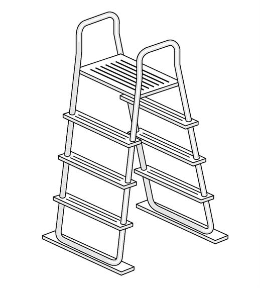
8.2.1 A - frame ladders
8.2.1.1 A-frame ladders shall have affixed the following or similar safety sign stating “NO DIVING” in a readable position above the water level on both the in-pool and entry side of the ladder
8.2.1.2 A-frame ladders shall have affixed on the pool side of the ladder the following or similar safety sign stating “TO PREVENT ENTRAPMENT OR DROWNING DO NOT SWIM THROUGH, BEHIND, OR AROUND LADDER.”
8.2.1.3 The instructions shall include the following statement, “FOR ENTRY / EXIT OF POOL, FACE THE LADDER AT ALL TIMES
8.2.1.4 Type A ladders
8.2.1.4.1 A double access ladder (Type A) shall have a safety sign affixed stating “REMOVE AND SECURE LADDER WHEN POOL IS NOT OCCUPIED
8.2.1.5 Type B ladders
8.2.1.5.1 Limited access ladders (Type B) shall have a safety sign affixed stating “SECURE LADDER WHEN POOL IS NOT
OCCUPIED.”
8.2.1.5.2 Type B A-frame ladders, which utilize a feature to limit accessibility, shall have affixed the following or similar safety sign: “WHEN POOL IS NOT OCCUPIED, SECURE THE LADDER TO PREVENT UNSUPERVISED ACCESS, ESPECIALLY BY YOUNG CHILDREN.” It is the manufacturer’s discretion to apply its signal word of choice.
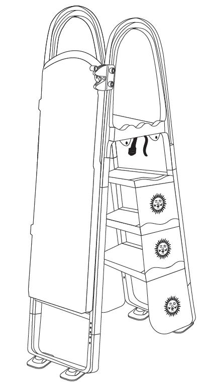
8.2.2 Type C staircase ladders
8.2.2.1 Staircase ladders, which swing up to secure or are removed to secure, shall have the following or similar safety sign affixed stating “WHEN NOT IN USE SWING-UP AND SECURE OR REMOVE.”
8.2.2.2 The ladder carton shall include a label that clearly states the specific pool wall or deck height, or range of pool wall or deck heights for which the ladder is designed and manufactured. The label shall state the following or equivalent: “THIS LADDER IS DESIGNED AND MANUFACTURED FOR A SPECIFIC, OR RANGE OF, POOL WALL HEIGHT(S) AND/OR POOL DECK HEIGHTS.”
8.2.3
Type
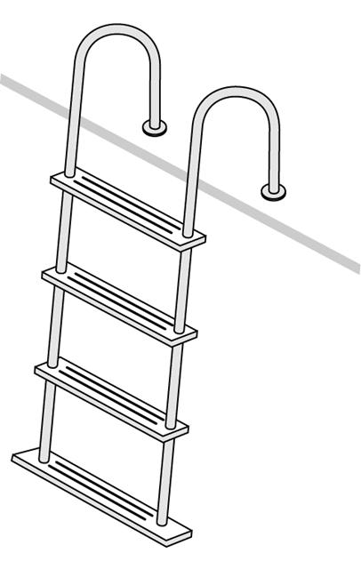
D in - pool ladders
8.2.3.1 In-pool ladders shall have affixed the following or similar safety sign stating “NO DIVING” in a readable position above the water level on both the in-pool and entry sides of the ladder.
8.2.3.2 In-pool ladders shall have affixed the following or similar safety sign stating “WARNING: TO PREVENT ENTRAPMENT OR DROWNING, DO NOT SWIM THROUGH, BEHIND, OR AROUND LADDER.”
8.2.3.3 The ladder carton shall include a label that clearly states the specific pool wall or deck height, or range of pool wall or deck heights for which the ladder is designed and manufactured. The label shall state the following or equivalent: “THIS LADDER IS DESIGNED AND MANUFACTURED FOR A SPECIFIC, OR RANGE OF, POOL WALL HEIGHT(S) AND/OR POOL DECK HEIGHTS.”
8.3 Type E, protruding in - pool stairs
8.3.1 Applicable safety signs shall be affixed
8.4 ANSI standards. All safety signs shall conform to the requirements of the ANSI/NEMA Z535 series of standards for safety signs and colors.
Figure 5 – Typical in-pool staircase ladder (Types E and F)
9 Aboveground/Onground Pool Ladders and Staircases
9.1 General Requirements
9.1.1 All pools shall have a means of entry/exit consisting of at least one ladder or a ladder and staircase combination (depending upon the pool/deck configuration). A ladder and staircase combination may consist of Type C and Type D, or Type C and Type E and Type F. Ladder Type A and Type B are constructed for entry/exit. (See Figures 1–5.)
9.1.2 Ladders and staircases shall conform to the following:
9.1.2.1 All ladder and staircase treads, which are integral or permanently attached, shall have a minimum static slip-resistance coefficient of 0.04 wet, when tested according to the recommended test method of the ASTM F462 Standard Consumer Safety Specification for Slip Resistant Bathing Facilities, utilizing a NIST Brungraber tester. Recommended test criteria should include tread in standing water consisting of droplets/puddles and not flowing water. Testing with soapy water shall not be required.
9.1.2.2 Ladders and staircases shall be made of corrosion-resisting materials
9.1.2.3 Ladders and staircases may include an adjustment mechanism for use with a sloping pool floor. Such adjustment mechanism is not required to address all possible combinations of slopes as permitted within this standard. Where adjustability is provided, the manufacturer shall provide installation parameters in accordance with Section 7.2.7.4.
9.2 Test requirements for Types A, B, C, D, E, and F ladders. The ladder shall be designed to withstand the test requirements as stated in Section 9.2.
9.2.1 All tests shall be conducted with the assembled ladder installed on a double layer of wedded 0.5 in. (12.7 mm ) plywood under the foot of the ladder.
9.2.1.1 All ladders shall be designed for a minimum working load of 224 lb. (102kg ) with the following ultimate load and factor of safety: Step Test 672 lb. (305kg ) 3:1.
9.2.2 Compression test. A compression test shall be performed on the assembled ladder in the operating position with the test load of 672 lb. (305kg ) applied over a 3.5 in. (89 mm) tread length at the center of the step or platform, whichever is higher. The assembled ladder shall not exhibit failure or permanent deformation
9.2.3 Step test. The strength of each step shall be tested by applying a 672 lb. (305
kg ) test load on a 3.5 in. (89 mm ) wide pad located on the centerline of each step. Each step shall withstand the test load without failure or permanent deformation.
9.2.4 Shear test. The shear strength of the step-to-step rail joint is measured by applying the test load of 448 lb. (203kg ) over 3.5 in. (89 mm ) of tread length as near to the joint as possible. On removing the load, there shall be no indication of failure in the fastener or in any other component. (See Section 9.3.1 for barrier requirements.)
9.2.5 Stability test. In the stability test, the ladder shall be set in the level operating position with the vertical test load of 224 lb. (102kg ) applied at the center of the top step or platform, whichever is higher. The ladder is then subjected to a horizontal test load applied at the center, side, and rear of the top step. During this test, the ladder base shall remain on the floor and be assembled and affixed per manufacturer’s instructions.
• Outside front stability: 60 lb. (27kg )
• Side stability: 35 lb. (16kg )
• Rear stability: 60 lb. (27kg )
9.3 A - frame ladders: Type A (double access) and Type B (limited access)
9.3.1 Ladders shall have a physical barrier to prevent children from swimming through the riser openings or behind the ladder, or meet the acceptance criteria of the entrapment test as described in Section 9.3.1.1
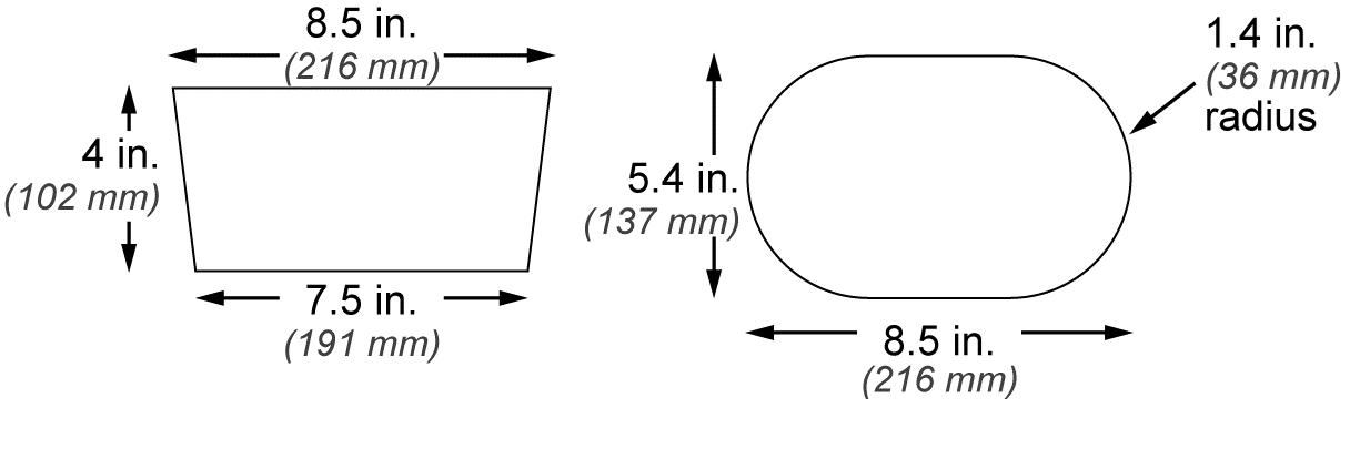
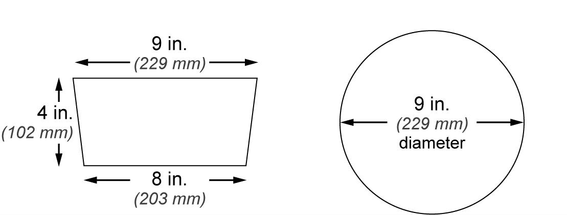
9.3.1.1 When tested for entrapment, ladders shall be fully assembled and placed over the side wall, or a representation thereof, of the above ground pool they are supplied with, or for which they are intended according to manufacturer’s recommendation. Torso and head test probes (Figures 6 and 7) shall be applied in each opening or area between the risers and behind the ladder in accordance with the test procedure for completely bounded openings of ASTM F1148-22.
Place the torso probe (see Figure 6) in the opening, tapered end first with the plane of its base parallel to the plane of the opening; rotate the probe while keeping its base parallel to the plane of the opening. If the base of the probe passes through the opening when it is rotated about its own axis in any orientation, place the head probe (see Figure 7) in the opening, tapered end first, while its plane is parallel to the plane of the opening.
Acceptance criteria for an opening is as follows:
(1) The opening does not admit the torso probe when it is rotated to any orientation about its own axis, or
(2) The opening admits the torso probe and also admits the head probe.
An opening is not in compliance with this standard if the opening admits the torso probe but does not admit the head probe.
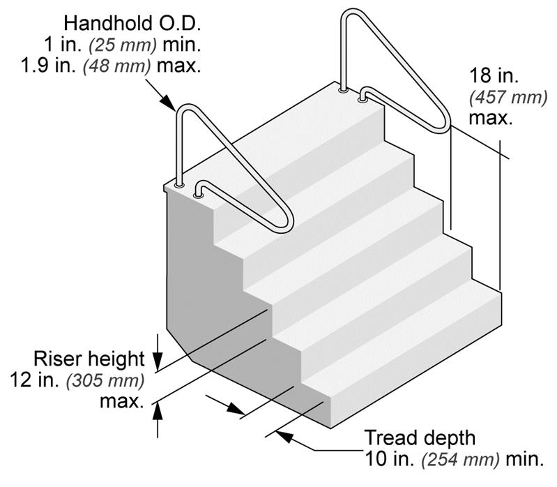
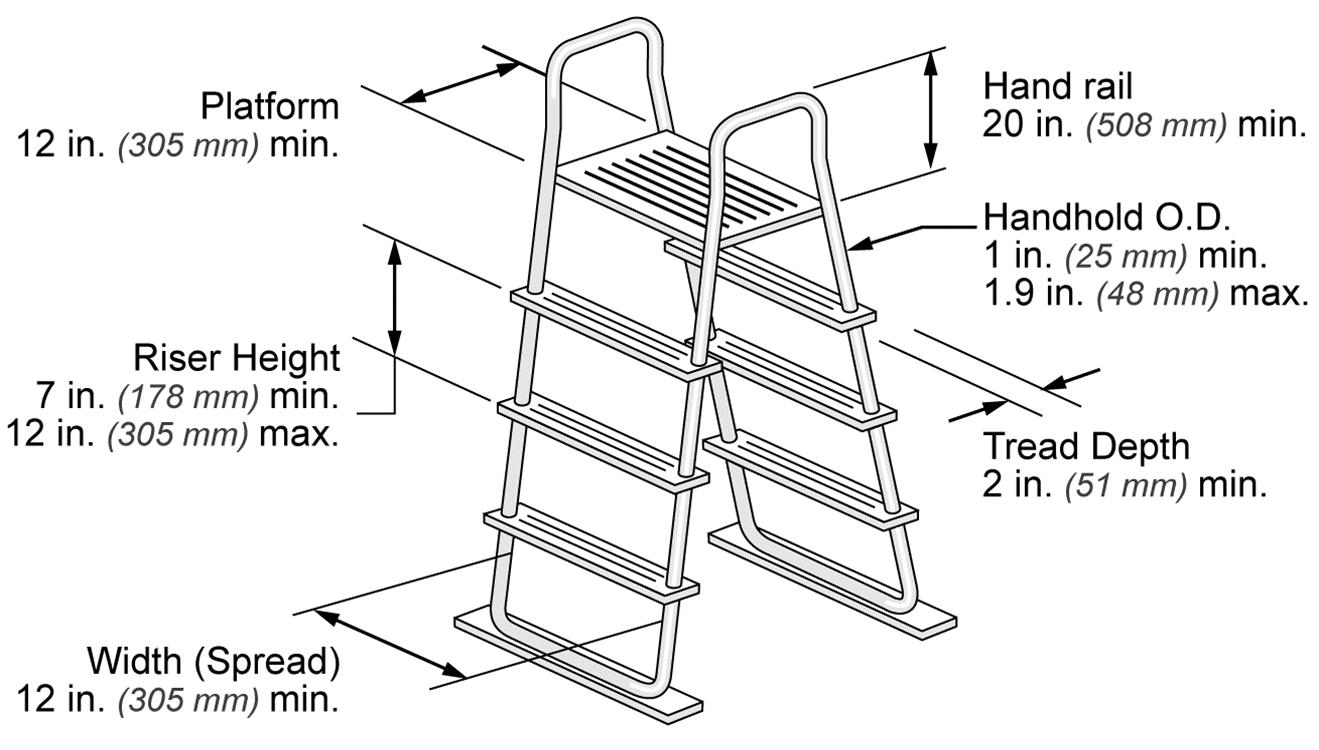
9.3.2 If an A-frame ladder has a platform between the handrails, the platform shall:
• Have a minimum width of 12 in. (305mm ) and a minimum length of 12 in. (305 mm);
• Be above or equal to the highest ladder treads; and
• Be slip resisting.
9.3.3 Handrails/handholds
9.3.3.1 A-frame ladders shall have two handrails/handholds that serve all treads.
9.3.3.2 A-frame ladders shall have two handrails/handholds with a minimum height of 20 in. (508 mm ) above the platform or uppermost tread, whichever is higher.
9.3.3.3 The outside diameter of handrails/handholds shall be a minimum of 1 in. (25 mm ) and a maximum of 1.9 in. (48 mm ) in diameter.
9.3.3.4 The clear distance between ladder handrails shall be a minimum of 12 in. (305 mm).
9.3.4 Treads
9.3.4.1 Ladder treads shall have a minimum horizontal uniform depth of 2 in. (51 mm).
9.3.4.2 Except for the bottom riser, there shall be a uniform riser height, with a
7 in. (178 mm ) minimum and 12 in. (305 mm) maximum. The vertical distance from the platform or top of the pool structure to the uppermost tread shall be uniform to other riser heights.
9.3.4.3 The height of the bottom riser can vary from the other risers. The bottom riser height shall not be less than 7 in. (178mm ) or greater than 12 in. (305 mm).
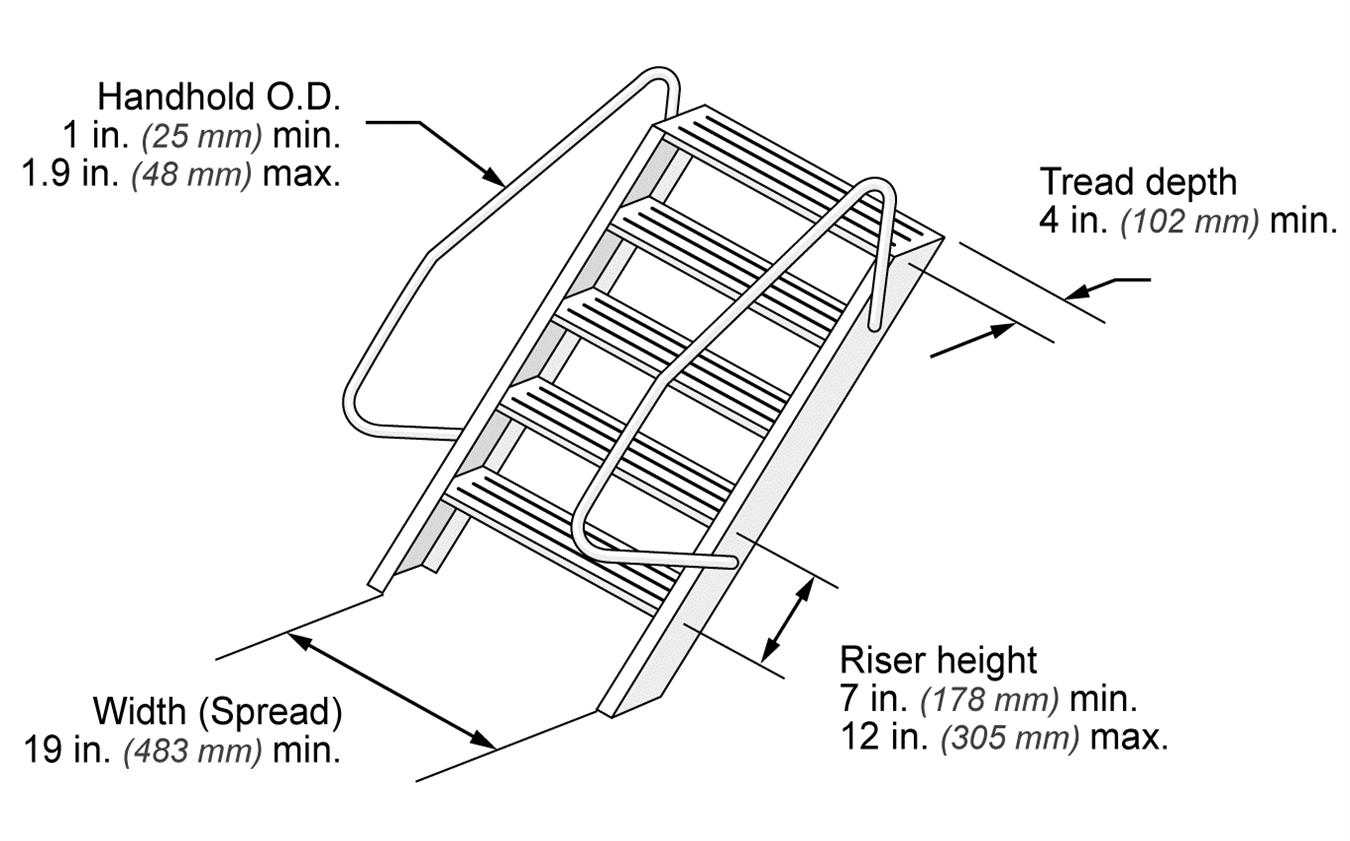
9.4.1.1 Staircase ladders shall have a minimum of two handrails/handholds that serve all treads.
9.4.1.2 Staircase ladders shall have two handrails/handholds with a minimum height of 20 in. (508 mm ) above the platform or uppermost tread, whichever is higher.
9.4.1.3 The outside diameter of handrails/handholds shall be a minimum of 1 in. (25 mm ) and a maximum of 1.9 in. (48 mm ) in diameter.
9.4.2 Treads
9.4.2.1 Ladder treads shall have a minimum horizontal uniform depth of 4 in. (102 mm).
Figure 9 – Dimensions for typical staircase ladder
9.4.2.2 Except for the bottom riser, there shall be a uniform riser height, with a 7 in. (178 mm ) minimum and 12 in. (305 mm) maximum. The vertical distance from the platform or top of the pool structure to the uppermost tread shall be uniform to other riser heights.
9.4.2.3 When using a staircase ladder with decks, the top step shall be flush with the deck, or be uniform height to other riser heights between 7 to 12 in. (178 to305 mm ) below the deck level.
9.4.2.4 The height of the bottom riser can vary from the other risers. The bottom riser height shall not be less than 7 in. (178mm ) or greater than 12 in. (305 mm).
9.4.2.5 All steps shall have a minimum unobstructed width of 19 in. (483 mm ) between the side rails.
9.5.1 There shall be a clearance of 3 in. (76 mm ) minimum and 6 in. (152 mm ) maximum between the pool wall and the ladder.
9.5.2 Handrails/handholds
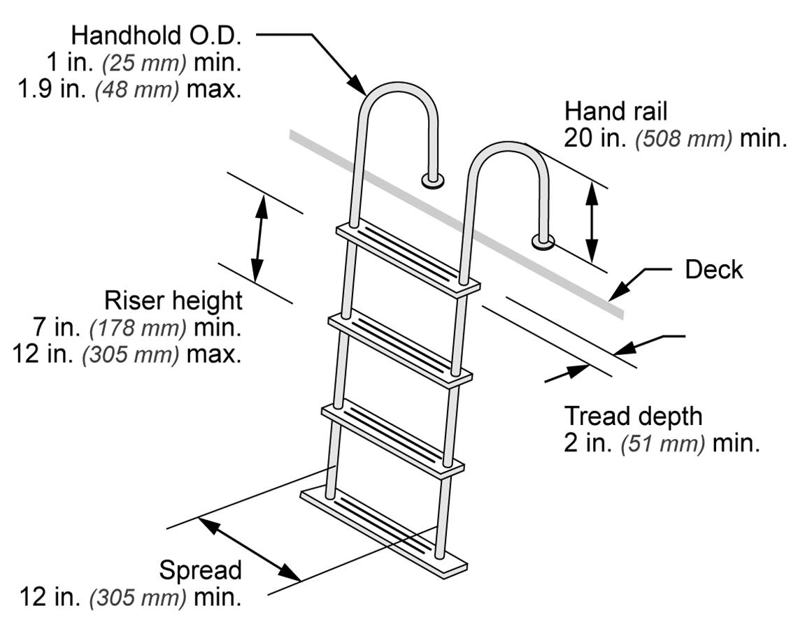
9.5.2.1 Ladders shall provide two handrails/handholds that extend above the platform or deck for a minimum of 20 in. (508mm).
9.5.2.2 The clear distance between ladder handrails shall be a minimum of 12 in. (305 mm).
9.5.2.3 The outside diameter of handrails/handholds shall be a minimum of 1 in. (25 mm ) and a maximum of 1.9 in. (48 mm ) in diameter.
Figure 10 – Dimensions for typical in-pool ladder
9.5.3 Treads
9.5.3.1 There shall be a uniform riser height, with a 7 in. (178 mm ) minimum and a 12 in. (305 mm ) maximum except for the following:
9.5.3.1.1 The height of the bottom riser can vary from the other risers, but the bottom riser height shall not be less than 7 in. (178 mm) or greater than 12 in. (305 mm).
9.5.3.1.2 The vertical distance from the pool coping, deck, or step surface to the uppermost tread shall be a minimum of 7 in. (178 mm ) and a maximum of 12 in. (305 mm ) and be uniform to other riser heights.
9.5.3.1.3 Ladder treads shall have a minimum horizontal uniform depth of 2 in. (51 mm).
TubAlliance.Allrights reserved.
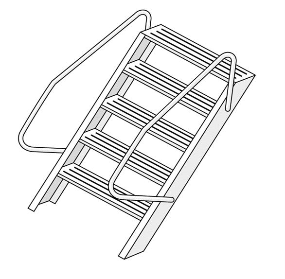
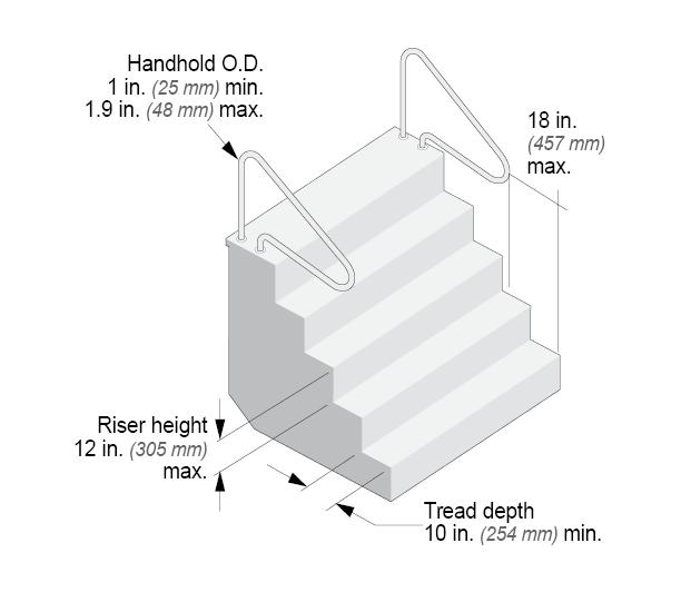
9.6 Type E, protruding in - pool stairs
Figure 11 – Dimensions for typical in-pool staircase ladder
9.6.1 In-pool stairs shall have a physical barrier to prevent children from swimming through the risers or behind the stairs.
9.6.2 Handrails/handholds. The design and construction of protruding pool stairs shall conform to Sections 9.6.2.1 and 9.6.2.2.
9.6.2.1 In-pool stairs shall provide a minimum of one handrail/handhold that serves all treads with a minimum height of 20 in. (508 mm ) above the platform or uppermost tread, whichever is higher.
9.6.2.2 Handrails, if removable, shall be installed in such a way that they cannot be removed without the use of tools.
9.6.2.2.1 The leading edge of handrails facilitating stairs and pool entry/exit shall be 18 in. ± 3 in. (457mm±76mm), horizontally from the vertical plane of the bottom riser (where applicable).
9.6.2.2.2 The outside diameter of handrails/handholds shall be a minimum of 1 in. (25 mm ) and maximum of 1.9 in. (48 mm ) diameter.
9.6.3 Risers, treads
Alliance.Allrights reserved.
9.6.3.1 Treads shall have a minimum unobstructed horizontal depth of 10 in. (254mm ) at all points and a minimum unobstructed surface area of 240 square in. (0.155 m2).
9.6.3.2 Risers at all points, except for the bottom riser, shall have a maximum uniform height of 12 in. (305 mm).
9.6.3.3 There shall be a uniform riser height with a 7 in. (178mm ) minimum and a 12 in. (305 mm ) maximum except for the following:
9.6.3.3.1 The height of the bottom riser can vary from the other risers, but the bottom riser height shall not be less than 7 in. (178 mm) or greater than 12 in. (305 mm).
9.6.3.3.2 The vertical distance from the pool coping, deck, or step surface to the uppermost tread shall be a minimum of 7 in. (178 mm ) and a maximum of 12 in. (305 mm ) and be uniform to other riser heights.
9.7 Type F, recessed in - pool stairs
9.7.1 In-pool stairs shall have a physical barrier to prevent children from swimming through the riser openings or behind the stairs.
9.7.2 Handrails/Handholds. If handrails/handholds are used, they shall conform to Sections 9.7.2.1 through 9.7.2.4.
9.7.2.1 In-pool stairs shall provide a minimum of one handrail/handhold that
serves all treads with a minimum height of 20 in. (508 mm ) above the platform or uppermost tread, whichever is higher.
9.7.2.2 Handrails, if removable, shall be installed in such a way that they cannot be removed without the use of tools.
9.7.2.3 The leading edge of handrails facilitating stairs and pool entry/exit shall be 18 in. ± 3 in. (457 mm ± 76 mm ) horizontally from the vertical plane of the bottom riser (where applicable).
9.7.2.4 The outside diameter of handrails/handholds shall be a minimum of 1 in. (25 mm ) and maximum of 1.9 in. (48 mm ) diameter.
9.7.3 Risers, treads. The design and construction of recessed pool stairs shall conform to Sections 9.7.3.1 through 9.7.3.2.
9.7.3.1 Treads shall have a minimum unobstructed horizontal depth of 10 in. (254mm ) at all points and a minimum unobstructed surface area of 240 sq. in. (0.155 m2).
9.7.3.2 There shall be a uniform riser height with a 7 in. (178mm ) minimum and a 12 in. (305 mm ) maximum, except for the following:
9.7.3.2.1 The height of the bottom riser can vary from the other risers, but the bottom riser height shall not be less than 7 in. (178 mm) or greater than 12 in. (305 mm).
9.7.3.2.2 The vertical distance from the pool coping, deck, or step surface to the uppermost tread shall be a minimum of 7 in. (178 mm ) and a maximum of 12 in. (305 mm ) and be uniform to other riser heights.
10 Aboveground/ O nground R aised D ecks and F encing
10.1 Deck structure. A cantilever style deck structure relies on the pool for support and it shall meet the pool manufacturer’s requirements. The pool manufacturer shall ascertain that the pool structure can support the deck. (See Figure 12.)
10.2 The deck shall be designed to support a live load of a minimum of 40 lb. per sq. ft. (195.3kg/m2) of the total deck area, based upon accepted engineering practices.
10.3 In a cantilever-type deck where the deck structure relies on the pool structure for support, the walking surface of the deck shall not exceed 1 in. (25 mm ) above the pool.
10.4 Unless cantilevered, the deck shall not exceed the height of the pool.
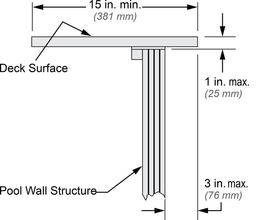
10.5.1 Decks that are installed flush with the top rail of the pool shall have all gap openings between the deck and top rails closed-off or capped.
10.5.2 Should the deck extend inside the top rail of the pool, it shall extend no more than 3 in. (76 mm ) beyond the inside of the top rail of the pool and be of a smooth finish.
10.5.3 The deck and deck surface shall be manufactured from materials that will provide slip resisting surfaces. As a guide, it is recommended that the deck and deck surface meet the requirements of Section 9.1.2.1.
10.6.1 Top rail. The top rail of the fence, mounted on top of the pool structure or deck of an aboveground/onground pool, shall be a minimum of 36 in. (914 mm) above the deck surface.
10.6.2 Spacing between pickets, support posts, and the top rail of the pool and the lower horizontal bottom rail of the fence shall not allow passage of a sphere greater than 4 in. (102mm ) to pass through the openings in the fence.
10.6.3 Where fencing is required and/or provided on the pool or deck, the fencing shall have at least 65 percent open area to allow visibility to the pool area and shall be constructed so as to eliminate or discourage climbing by young children.
10.7 Materials. Fence and deck surfaces shall be of nontoxic materials. As a guide, the following standards may be referenced:
• American Wood Preservers Association (AWPA) Standard C2-02, Lumber, Timber, Bridge Ties, and Mine Ties Preservative Treatment by Pressure Processes
• American Wood Preservers Association Standard C9-02, Plywood–PreservativeTreatmentbyPressureProcesses.
• American Wood Preservers Association Standard C22, Permanent Wood Foundations.
• FederalHazardousSubstancesAct16CFR,Ch.II.
Figure 13 – Typical free-standing deck support
10.8 Signage. The deck/fence package shall include a safety sign to address “NO DIVING” to be affixed at point of entry.
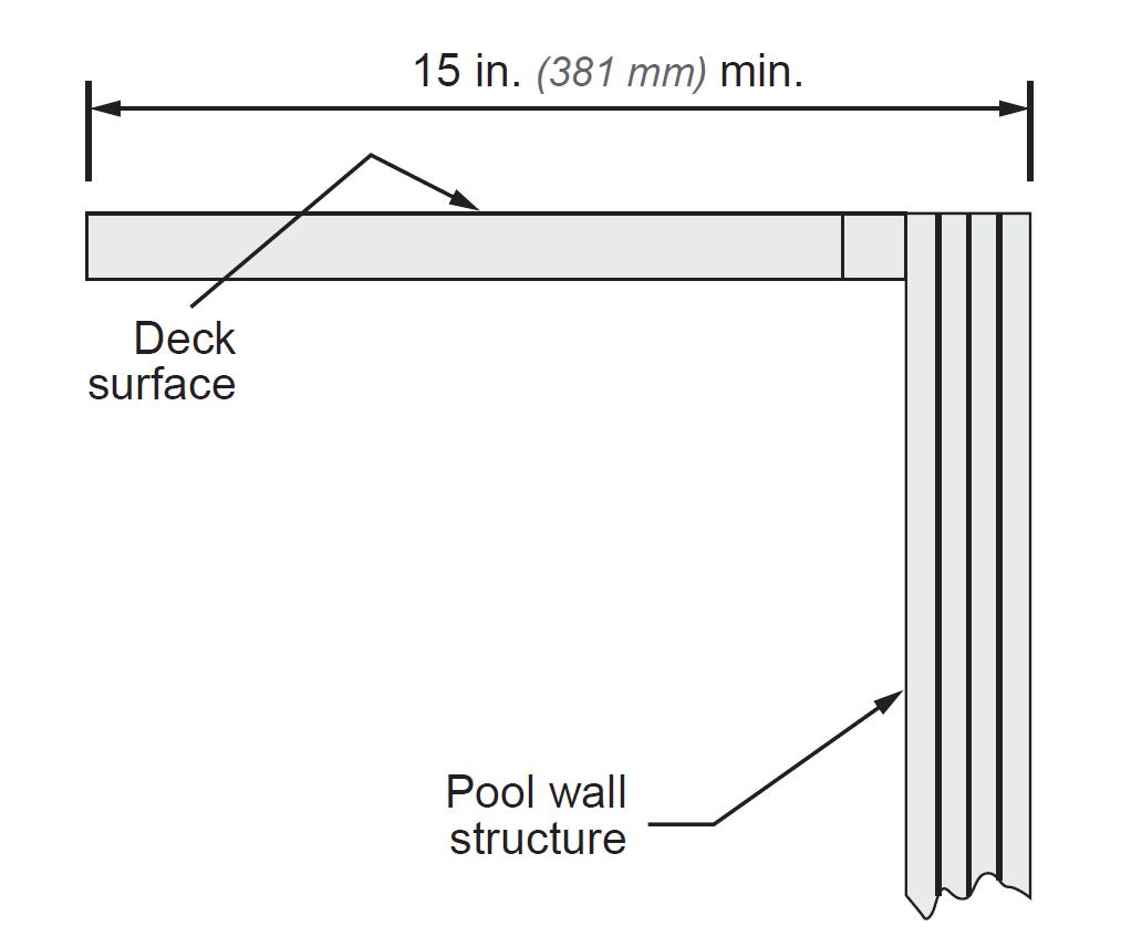
10.9 Walk - around decks. Walk-around decks shall be a minimum level distance of 15 in. (381mm ) wide of level walking surface, measured from the inside edge of the pool top rail to the outside of the pool walk-around, and shall be fitted with a fence consistent with the requirements of Section 10. (See Figure 13.)
11 Aboveground/ O nground Sw imming P ool C irculation C omponents and R elated
E quipment
11.1 A circulation system consisting of pumps, hoses, tubing, piping, return inlets, suction outlets, filters, and other related equipment that provides for circulation of water throughout the pool shall be located to prevent being used as a means of access to the pool, especially by young children.
11.1.1 Draining the system. In climates subject to freezing, circulation system equipment shall be designed and fabricated to drain the pool water from the equipment, together with exposed piping, by removal of drain plugs and manipulating valves or by other methods. Refer to the component manufacturer's instructions for specific information on draining the system.
11.1.2 Turnover. The equipment shall be sized to provide a turnover of the pool water at least once every 12 hours. The system shall be designed to give the proper turnover rate based on the manufacturer’s specified maximum flow rate of the filter, in clean media condition of the filter.
11.1.3 Water clarity. Water clarity shall be maintained. Clarity is a function of proper filtration and maintenance of proper chemical operational parameters in the most current published edition of ANSI/APSP/ICC-11. Pool water shall be of a clarity to permit a Secchi or other object located on the bottom of the pool at its deepest point to be clearly visible and sharply defined from any point outside the pool in a direct line of sight.
11.1.4 Accessibility for inspection. Circulation system components that require replacement or servicing shall be accessible for inspection, repair, or replacement and shall be installed according to the instructions.
11.1.5 Circulation equipment shall be installed per the instructions to provide proper mounting and support, to prevent damage from misalignment, settlement, and vibration, and to minimize the potential for the accumulation of debris and moisture.
11.2 Suction Entrapment Avoidance
11.2.1 Suction Outlet Fitting Assembly (SOFA) certifications. When used, manufactured SOFAs, fully submerged Suction Outlet Fitting Assemblies (SOFAs), including associated fittings, fasteners, and components, shall be certified by an agency accredited to ISO 17065 as conforming to the most current published edition of ANSI/APSP/ICC-16 incorporated into the Virginia Graeme Baker Pool and Spa Safety Act.
11.2.2 Suction entrapment avoidance. The design, and any installation instructions for all suction outlets (SOFAs, skimmers, and vacuum port fittings), when
used, shall be in accordance with the most current published edition of ANSI/PHTA/ICC-7.
11.3 Piping and fittings. The circulation system composed of hoses, tubing, piping, and fittings shall be considered to be process piping and shall be made of non-toxic material and able to withstand operating at 1.5 times the rated pressure of the pump.
11.3.1 The suction piping shall not collapse when there is complete shutoff of flow on the suction side of the pump.
11.3.2 Water velocity. The water velocity in the pool piping shall not exceed 8 ft. (2.44 m ) per second for both suction and pressure piping.
11.4 Filters
11.4.1 Filters. Swimming pool filters shall be rated for the operating pressure of the circulation system.
11.4.2 Filters shall be designed so that after cleaning per the instructions, the system can provide the water clarity noted in Section 11.1.3 and in the most current published edition of ANSI/APSP/ICC-11.
11.5 Internal pressure. Pressure-type filters shall provide an automatic internal or a manual external means to relieve accumulated air pressure inside the tank. Filter tanks composed of upper and lower tank lids that are held in place by a perimeter clamp shall provide a slow and safe release of air pressure before the clamp disengages the lids.
11.5.1 Any filter incorporating an automatic internal air relief as its principal means of air release shall have a means to provide a slow and safe release of pressure as a part of its design.
11.5.2 As a part of its design, any separation tank used in conjunction with any filter tank shall have a manual means of air release or a means to provide a slow and safe release of pressure as it is opened.
11.5.3 Instructions. Pressure filters shall have operation instructions permanently installed on the filter. Filters with manual air release shall include a precautionary statement or warning not to start up the system without first opening the air release. The statement shall be visible and noticeable within the area of the air release.
11.6 Filter tanks shall be designed for a pressure equal to the rated head of the pump with a minimum 4:1 safety factor.
11.7 Pressure or vacuum gauge. A pressure or vacuum gauge or other means of indicating system conditions shall be provided in the circulation system in an easily readable location.
11.8 Pumps
11.8.1 Swimming pool pumps shall be tested and certified by a nationally recognized testing laboratory in accordance with UL 1081.
11.8.2 Horsepower rating. Pump horsepower rating and labeling shall not exceed the brake horsepower of the motor.
11.8.3 A pump and motor shall be provided for circulation of the pool water. The performance of all pumps shall meet or exceed the conditions (if applicable) of flow required for filtering and cleaning the pool against the total dynamic head developed by the complete system. System flow shall not exceed the filter manufacturer’s maximum flow rate.
11.8.4 With all pressure filter systems, a cleanable strainer or screen shall be provided upstream of the circulation pump(s) to remove solids, debris, hair, lint, etc.
11.8.5 Pump(s) and motor(s) shall be accessible for inspection and service as per the instructions and specifications.
11.8.6 The design and construction of the pump(s) and its component parts shall provide safe operation that is not hazardous to the operator or maintenance personnel.
11.8.7 Where a mechanical pump seal is provided, components of the seal shall be corrosion-resisting and capable of operating under conditions normally encountered in pool operation.
11.8.8 Motor(s) shall be capable of operating the pump(s) under full load with a voltage variation of ±10 percent from the nameplate. The nameplate Full Load Amps (FLA) shall not be exceeded by more than 10 percent.
11.8.9 There shall be an easily accessible means of shut-off of the suction and discharge lines for maintenance and removal of the pump.
11.9 Surface skimmer systems
11.9.1 Any surface skimming system provided on aboveground/onground residential swimming pools shall be designed and constructed to skim the pool surface when the water level is maintained between the minimum and maximum fill level of the pool.
11.9.2 Skimming devices shall be designed and installed so as not to constitute a hazard to the user.
11.9.3 When surface skimmers are used as the sole outlet system, at least one surface skimmer shall be provided for each 800 sq. ft. (74 m2) or fraction
thereof of the water surface area. When skimmers are used, they shall be located to optimize skimming action over the surface of the pool.
11.9.4 Skimmers shall be equipped with a vent to serve as a vacuum break.
11.9.5 When surface skimmers are used to provide only a fraction of the outlet system flow, they shall be considered to cover only that fraction of the 800 sq. ft. (74 m2) as defined in Section 11.9.3.
11.10 Circulation and pump controls
11.10.1 The circulation system shall be designed to accommodate 100 percent of the turnover flow rate.
11.10.2 Suction outlets and return inlets shall be provided and arranged to produce a uniform circulation of water and maintain the distribution of sanitizer residual throughout the pool.
11.10.3 Timing/electronic and related devices. The circulation system shall be capable of maintaining water clarity and water chemistry requirements. Time clocks and/or other related devices are permitted to set the operating period of the circulation devices.
Alliance.Allrights reserved.
11.10.4 When appurtenant devices such as chemical/sanitizer feeders, heaters, and other devices are used, they shall be electrically tied into a timing or electronic device (where applicable) when they are dependent upon circulation pump flow. See device’s specifications.
11.11 Heaters
This section pertains to appliances using either fossil fuels such as natural gas, propane (LPG), #2 fuel oil, or electric heating equipment for heating pool water.
11.11.1 Heaters shall be tested and shall comply with the requirements of CSA/ANSI Z21.56-19/CSA 4.7-2019 and/or UL 1261. Heat pumps shall comply with UL 60335-1 and UL 60335-2-40 and shall be listed by a nationally recognized testing laboratory.
11.11.2 Owner/operator shall routinely check the in-pool water to ensure that the temperature does not exceed 104 °F (40 °C). If adjustments are necessary, those adjustments shall be performed in accordance with the operating instructions or by a qualified technician.
11.11.2.1 Sizing. For efficient and economical operation, it is important that the heater be properly sized. Determine the proper size heater by first determining the area of the swimming pool in square feet. Then select from the manufacturer’s charts the heater that is properly sized for that particular pool.
11.11.2.2 Installation. The heater(s) shall be installed in accordance with all federal, state, and local codes as well as the manufacturer’s recommendations.
11.11.2.3 Support. Heaters shall be installed on a surface with sufficient structural strength to support the heater when it is full of water and operating. The heater shall be level after plumbing, gas, and/or electrical connections are completed.
11.11.2.4 Combustible surfaces. If a heater requires a non-combustible surface per the installation instructions, it shall be placed on a cement surface or other accepted surface per CSA/ANSI Z21.56-19/CSA 4.7-2019 or as per federal, state, or local codes.
11.11.2.5 Clearances. When installing a heater, adequate clearances shall be maintained on all sides and over the top of the unit. Consult the installation instructions for proper clearance.
11.11.2.6 Ventilation. The heater shall have adequate ventilation to ensure proper operation in accordance with the installation instructions.
Alliance.Allrights
11.11.2.7 Makeup air. When installing a fossil fuel heater indoors, proper openings to the room are a necessity. The heater shall be installed in accordance with federal, state, or local codes and the installation specifications.
11.11.3 Heating energy sources
11.11.3.1 Natural gas energy supply. The heater gas supply piping shall comply with installation specifications and NFPA 54.
11.11.3.1.1 Important Safety Note: Install a gas cock, properly sized and readily accessible outside the jackets, to stop the flow of natural gas at the heater for service or emergency shutdown.
11.11.3.2 Propane energy supply. Whenever a propane (LPG) appliance is installed, special attention shall be given to ensure that the storage tank, supply piping, and regulator shall be adequately sized to ensure operating fuel pressures as specified by the appliance manufacturer. Consult the fuel supply company and ensure that the system is installed in accordance with NFPA 54 and NFPA 58.
11.11.3.2.1 Important Safety Note: Propane gas is heavier than air and therefore can create an extreme hazard of explosion or suffocation if the heater is installed in a pit or enclosed area. The NFPA 54 and NFPA 58 contain a provision to install valves and other controls in pits and similar areas.
11.11.3.2.2 Important Safety Note: Install a gas cock, properly sized and readily accessible outside the jacket, to stop the flow of propane (LPG) at the heater for service or emergency shutdown.
11.11.3.3 Electrical energy supply. Electric heating appliances shall be installed in accordance with Article 680 of the NFPA 70 and any federal, state, or local codes.
11.11.3.3.1 Important Safety Note: Grounding and Bonding. To reduce the hazard of electrical shock, the requirements for grounding and bonding are particularly important and shall be adhered to.
11.11.3.3.1.1 Heater circulation system water flow through the heater, any bypass plumbing installed, any back-siphoning protection, and the use of CPVC Sch. 80, or heat sinks, or the equivalents shall be in accordance with the installation specifications and local codes.
11.11.4 Special consideration. When the operating instructions recommend that the heater be turned off prior to stopping the water flow, the use of mechanisms such as a “fireman’s switch” may be used. This device is used to turn the heater off before the pump is turned off to ensure that the heater cools off properly.
N ote : The “fireman’s switch” does not protect against a manual override or a system shutdown in the event of power failure.
11.11.5 Heaters shall be located to prevent being used as a means of access to the pool, especially by young children.
12 Water S upply
12.1 Treatment. The water supply serving the pool, which comes from a variety of sources, shall meet the requirements of the most current published edition of ANSI/APSP/ICC-11 before the bather uses the pool.
12.2 Backflow. No direct mechanical connection shall be made between the potable water supply and the pool, sanitizing equipment, or the system of piping for the pool, unless it is protected against back-pressure in a manner approved by the state or local authority or through an air gap that complies with ASME A112.1.2, or other equivalent means approved by the state or local authority.
13 Waste W ater D isposal
13.1 Backwash water may be permitted to discharge into a sanitary sewer through an approved air gap, into an approved surface disposal system, or by other means approved by state or local authority.
14 Sanitizing E quipment, O xidation E quipment, UV L ight U nits, and C hemical F eeders
14.1 Compliance. When chemical feeders are used to add the sanitizing agent to the pool or spa water, the chemical feeders shall be capable of introducing a sufficient quantity of an EPA-registered sanitizing agent to maintain the appropriate residual concentrations.
14.1.1 Electrically operated chemical feeders, UV light units, and ozone generators shall be tested and approved by a nationally recognized testing laboratory.
14.2 Chemical feeders. Manufacturer’s specifications shall be used when installing and maintaining chemical feeders, and using the chemical compound specified by the manufacturer.
14.2.1 Chemical feed systems shall be installed so they cannot operate unless there is return flow to properly disperse the chemical throughout the pool as designed. If the device has an independent timer, the filter and chemical feed pump timers shall be interlocked.
14.2.2 Floating chemical dispensers shall not be used when bathers are in the pool.
14.3 Supplemental treatment equipment. The installation and use of ozonegenerating equipment shall conform to the installation specifications.
14.3.1 Supplemental treatment equipment shall be used in conjunction with an EPA-registered sanitizer and other chemical treatments to meet the chemical operating parameters.
14.3.2 Manufacturer’s specifications shall be used to determine where and how these units shall be installed within the circulation system.
15 Electrical R equirements
15.1 All electrical components installed in and/or adjacent to an aboveground/onground residential swimming pool shall be installed in accordance with and shall comply with the requirements of NFPA 70 Article680, Swimming Pools, Spas, Hot Tubs, Fountains, and Similar Installations , and any state or local code. To apply the NEC’s interpretation of electrical requirements for pools, see Sections 15.2.1 and 15.2.2.
15.2 Lighting, when installed, shall be in accordance with NFPA 70 Article680and local codes.
15.2.1 The NationalElectricalCodedefines a Storable Swimming or Wading Pool as a pool used for Swimming, Wading, or Immersion, and Therapeutic. (Storable Immersion Pool). (Storable Pool) Pools installed entirely on or above the ground that are intended to be stored when not in use and are designed for ease of relocation, regardless of water depth.
15.2.2 The National Electrical Code defines Permanently Installed Swimming, Wading and Therapeutic Pools as pools that are constructed or installed in the ground or partially in the ground, and all pools installed inside of a building, whether or not served by electrical circuits of any nature
15.3 Underwater lighting
15.3.1 Submersible pool lighting to illuminate the water for the user shall comply with NFPA 70, Articles680.23Underwaterluminaires(LightingFixtures),680.23(A) General, 680.23(A) (1) Luminaire Design, Normal Operation, 680.23(B) Wetniche luminaires (fixtures), 680.23(C) Dry-niche luminaires (fixtures) , and UL 676.
15.3.2 Underwater lights having front access shall be installed and removed only with the use of tools.
15.4 Receptacles. Pool shall be located at a minimum distance of 6 ft. (1.83m ) from any receptacle, and all 125-volt 15- and 20-ampere receptacles located within 20 ft. (6.1 m ) of the pool shall be protected by a ground fault circuit interrupter (GFCI), where distances are found by measuring the shortest path the supply cord of an appliance connected to the receptacle would follow, without piercing a floor, wall, ceiling, doorway with hinged or sliding door, window opening, or other effective permanent barrier, to the inside wall of the pool.
ANSI/PHTA/ICC-4 2025
Approved February 20, 2025 American National Standard for Aboveground/Onground Residential Swimming Pools
This standard provides recommended minimum guidelines for the design, equipment, operation, and installation of aboveground/onground residential swimming pools. This is an essential document for the pool and hot tub industry, and especially for manufacturers and producers of aboveground/onground residential swimming pools.