


Number 01, January 2016
IEM Registered on 1 May 1959
MAJLIS BAGI SESI 2015/2016 (IEM COUNCIL SESSION 2015/2016)
YANG DIPERTUA / PRESIDENT
Y.Bhg. Dato’ Ir. Lim Chow Hock
TIMBALAN YANG DIPERTUA / DEPUTY PRESIDENT
Ir. Tan Yean Chin
NAIB YANG DIPERTUA / VICE PRESIDENTS
Y.Bhg. Dato’ Ir. Dr Andy Seo Kian Haw, Ir. Lee Weng Onn, Ir. Gopal Narian Kuty, Ir. Prof. Dr
Ruslan bin Hassan, Ir. Lai Sze Ching, Ir. Lee Boon Chong, Ir. David Lai Kong Phooi
SETIAUSAHA KEHORMAT / HONORARY SECRETARY
Ir. Yam Teong Sian
BENDAHARI KEHORMAT / HONORARY TREASURER
Ir. Prof. Dr Jefrey Chiang Choong Luin
BEKAS YANG DIPERTUA TERAKHIR / IMMEDIATE PAST PRESIDENT Ir. Choo Kok Beng
BEKAS YANG DIPERTUA / PAST PRESIDENTS
Y.Bhg. Academician Tan Sri Dato’ Ir. (Dr) Hj. Ahmad Zaidee bin Laidin, Y.Bhg. Dato’ Ir. Dr
Gue See Sew, Y.Bhg. Academician Dato’ Ir. Prof. Dr Chuah Hean Teik, Ir. Vincent Chen Kim Kieong
WAKIL AWAM / CIVIL REPRESENTATIVE
Ir. Prof. Dr Mohd. Zamin bin Jumaat
WAKIL MEKANIKAL / MECHANICAL REPRESENTATIVE
Ir. Dr Kannan M. Munisamy
WAKIL ELEKTRIK / ELECTRICAL REPRESENTATIVE
Y.Bhg. Dato’ Ir. Ali Askar bin Sher Mohamad
WAKIL STRUKTUR / STRUCTURAL REPRESENTATIVE
Ir. Hooi Wing Chuen
WAKIL KIMIA / CHEMICAL REPRESENTATIVE
Ir. Prof. Dr Thomas Choong Chean Yaw
WAKIL LAIN-LAIN DISPLIN / REPRESENTATIVE TO OTHER DISCIPLINES
Ir. S. Kumar a/l Subramaniam
WAKIL MULTIMEDIA DAN ICT / ICT AND MULTIMEDIA REPRESENTATIVE
Engr. Abdul Fatah bin Mohd. Yaim, M.I.E.M.
AHLI MAJLIS / COUNCIL MEMBERS
Ir. Dr Tan Chee Fai, Ir. Tiong Ngo Pu, Ir. Yau Chau Fong, Ir. Teh Piaw Ngi, Ir. Kim Kek
Seong, Ir. Chong Chin Meow, Ir. Chin Kuan Hwa, Ir. Assoc. Prof. Dr Vigna Kumaran
Ramachandaramurthy, Ir. Lee Cheng Pay, Ir. Ong Ching Loon, Ir. Gary Lim Eng Hwa, Y.Bhg. Dato’ Ir. Noor Azmi bin Jaafar, Ir. Aminuddin bin Mohd Baki, Ir. Mohd Radzi bin
Salleh, Ir. Ong Sang Woh, Ir. Mohd Khir bin Muhammad, Ir. Assoc. Prof. Dr Norlida Bini
Buniyamin, Y. Bhg. Dato’ Ir. Hanapi bin Mohamad Noor, Ir. Dr Ahmad Anuar bin Othman, Ir. Ishak bin Abdul Rahman, Ir. PE Chong, Ir. Ng Yong Kong, Ir. Tejinder Singh, Ir. Sreedaran a/l Raman, Ir. Roger Wong Chin Weng
AHLI MAJLIS JEMPUTAN / INVITED COUNCIL MEMBERS
Y. Bhg. Datuk Ir. Rosaline Ganendra, Y. Bhg. Dato’ Ir. Abdul Rashid bin Maidin, Y.Bhg. Dato’ Ir. Mohd Azmi bin Ismail
PENGERUSI CAWANGAN / BRANCH CHAIRMAN
1. Pulau Pinang: Ir. Dr Mui Kai Yin
2. Selatan: Ir. Assoc. Prof. Hayai bini Abdullah
3. Perak: Ir. Lau Win Sang
4. Kedah-Perlis: Ir. Hj. Abdullah bin Othman
5. Negeri Sembilan: Ir. Shahrin Amri bin Jahari
6. Kelantan: Ir. Mohamad Zaki bin Mat
7. Terengganu: Ir. Abdullah Zawawi bin Haji Mohd. Noor
8. Melaka: Ir. Nur Fazil Noor Mohamed
9. Sarawak: Ir. Haidel Heli
10. Sabah: Ir. Yahiya bin Awang Kahar
11. Miri: Ir. Steven Chin Hui Seng
12. Pahang: Y. Bhg. Dato’ Ir. Hj. Abdul Jalil bin Hj. Mohamed
AHLI JAWATANKUASA INFORMASI DAN PENERBITAN / STANDING COMMITTEE ON INFORMATION AND PUBLICATIONS 2015/2016
Pengerusi/Chairman: Ir. Prof. Dr Ruslan Hassan Naib Pengerusi/Vice Chairman: Ir. Mohd. Khir Muhammad Seiausaha/Secretary: Ir. Lau Tai Onn Ketua Pengarang/Chief Editor: Ir. Prof. Dr Ruslan Hassan Pengarang Bulein/Bullein Editor: Ir. Mohd. Khir Muhammad Pengarang Prinsipal Jurnal/Principal Journal Editor: Ir. Prof. Dr Dominic Foo Chwan Yee Pengerusi Perpustakaan/Library Chairman: Ir. C.M.M. Aboobucker Ahli-Ahli/Commitee Members: Y.Bhg. Datuk Ir. Prof. Dr Ow Chee Sheng, Engr. Abdul Fatah bin Mohamed Yaim M.I.E.M., Ir. Dr Kannan a/l M. Munisamy, Ir. Chin Mee Poon, Ir. Yee Thien Seng, Ir. Ong Guan Hock, Engr. Dr Wang Hong Kok F.I.E.M., Ir. Dr Oh Seong Por, Ir. Dr Aminuddin Mohd Baki, Ir. Tejinder Singh
LEMBAGA PENGARANG/EDITORIAL BOARD 2015/2016 Ketua Pengarang/Chief Editor: Ir. Prof. Dr Ruslan Hassan Pengarang Bulein/Bullein Editor: Ir. Mohd. Khir Muhammad Pengarang Jurnal/Journal Editor: Ir. Prof. Dr Dominic Foo Chwan Yee Ahli-ahli/Commitee Members: Ir. Ong Guan Hock, Ir. Lau Tai Onn, Ir. Yee Thien Seng, Engr. Dr Wang Hong Kok F.I.E.M.
Secretariats: Janet Lim, May Lee

COVER NOTE
Finalising Malaysian National Annex (NA) on Eurocode 8 (EC8): Design of Structures for Earthquake Resistance 5
COVER STORY
Development of Malaysia’s National Annex to Eurocode on Earthquake Resistance ..................6 6 - 10
FEATURE ARTICLES
Evolution of IEM Study Group ..............................12
Elastic Response Spectrum Models for Rock Sites ............................................................16
Site Classiication and Elastic Response Spectrum Model for Soil Sites ..............................20 Performance Criteria and Design Parameters ......30
Static and Dynamic Analysis Methods ..................36
Summary Update of Cost Implication on Proposed Malaysian NA for EC8 on Ofice Buildings and Link Houses ...........................42
TREKKING Magical White Cliffs of Mons Klint
Interview
PAGE
Membership List 48


By
Dr Jeffrey Chiang, currently IEM Honorary Treasurer, has previously served as IEM Honorary Secretary, Chairman of IEM Civil & Structural Engineering Technical Division, Chairman of IEM-SWO Technical Committee on Wind Loads, as well as Secretary of IEM-SWO Technical Committee on Eurocode
2 Concrete Structures Design. Dr Chiang is the Dean of the Faculty of Engineering & the Built Environment in SEGI University, Kota Damansara Campus, Petaling Jaya.
Finalising Malaysian National Annex (NA) on Eurocode 8 (EC8): Design of
This is the last segment on the National Annex To Eurocode 8, which will be available for public comment soon. Apart from a word of thanks to the Technical Committee and Working Group members involved in the finalisation of the standards document, I would also like to thank the International Panel of Experts and Advisors for voluntary services rendered since 2008.
We had a fruitful and eye-opening dialogue session with Sabah engineers, Government officials and other stakeholders in early December 2015, to hear their opinions on how the National Annex should reflect the experience of Sabah residents in view of local earthquakes there. The Technical Committee and the Working Group involved were committed to ensuring that the standards would uphold the intention to keep and maintain public safety. At the same time, where there was a possibility to adjust to accommodate, the Study Group in the Technical Committee worked tirelessly to review additional data supplied by the Sabah stakeholders.
To that end, the finalised version of the Malaysian National Annex will be truly representative of the expectations of all stakeholders in Peninsular Malaysia, Sabah and Sarawak – in terms of the recommendations there in for the peak ground acceleration values and other related design parameters, to be adopted for the design of building structures for the relevant return periods for a range of building structures. NA to EC8 is unique because it provides recommended response spectra to cover for far distance earthquakes as well as local earthquake events.
Last but not least, sincere thanks also go to the secretariat staff of IEM for their hard work in planning and administering the running of the Technical Committee and its activities, especially in organising meetings, courses, seminars, workshops and symposia over the years, since the inception of the Technical Committee.
DIMENSION PUBLISHING SDN. BHD. (449732-T)
Level 18-01-03, PJX-HM Shah Tower, No. 16A, Persiaran Barat, 46050 Petaling Jaya, Selangor Darul Ehsan, Malaysia. Tel: +(603) 7493 1049 Fax: +(603) 7493 1047 E-mail: info@dimensionpublishing.com Website: www.dimensionpublishing.com
For adverisement placements and subscripions, please contact: DIMENSION PUBLISHING SDN. BHD. (449732-T) at +(603) 7493 1049, or E-mail: info@dimensionpublishing.com
Subscripion Department E-mail: info@dimensionpublishing.com
Printed by
HOFFSET PRINTING SDN. BHD. (667106-V) No. 1, Jalan TPK 1/6, Taman Perindustrian Kinrara, 47180 Puchong, Selangor Darul Ehsan, Malaysia. Tel: +(603) 8075 7222 Fax: +(603) 8075 7333
Mailer
MAIL SERVICES (648839-P)
14 Jalan TSB 2, Taman Perindustrian Sungai Buloh, Sungai Buloh, Selangor Darul Ehsan, Malaysia. Tel: +(603) 6156 5288
JURUTERA MONTHLY CIRCULATION: 36,000 COPIES
Submission or placement of aricles in JURUTERA could be made to the:Chief Editor
THE INSTITUTION OF ENGINEERS, MALAYSIA (IEM) Bangunan Ingenieur, Lots 60 & 62, Jalan 52/4, P.O. Box 223 (Jalan Sultan), 46720 Petaling Jaya, Selangor. Tel: +(603) 7968 4001/4002 Fax: +(603) 7957 7678
E-mail: pub@iem.org.my or sec@iem.org.my IEM Website: htp://www.myiem.org.my © 2016, The Insituion of Engineers, Malaysia (IEM) and Dimension Publishing Sdn. Bhd.
Chairman ROBERT MEBRUER CEO/Publisher PATRICK LEUNG
General Manager SHIRLEY THAM shirley@dimensionpublishing.com
Head of Markeing & Business Development JOSEPH HOW joseph@dimensionpublishing.com
Editor TAN BEE HONG bee@dimensionpublishing.com
Contribuing Writers PUTRI ZANINA & ZOE PHOON putri@dimensionpublishing.com zoe@dimensionpublishing.com
Senior Graphic Designer SUMATHI MANOKARAN sumathi@dimensionpublishing.com
Graphic Designer NABEELA AHMAD beela@dimensionpublishing.com
Adverising Consultants AZIM SHAARI & THAM CHOON KIT azim@dimensionpublishing.com ckit@dimensionpublishing.com
Accounts cum Admin Execuive YEN YIN yenyin@dimensionpublishing.com
PUBLICATION DISCLAIMER
The publicaion has been compiled by both IEM and Dimension with great care and they disclaimanydutytoinvesigateanyproducts,process,services,designsandthelikewhichmay be described in this publicaion. The appearance of any informaion in this publicaion does notnecessarilyconsituteendorsement by IEMand Dimension. Thereisnoguaranteethat the informaioninthis publicaionisfreefromerrors.IEMandDimensiondonotnecessarilyagree with the statement or the opinion expresssed in this publicaion.
COPYRIGHT JURUTERA Bullein of IEM is the oicial magazine of The Insituion
The fruit of the labour to realise the completion of the inal version of the Malaysian National Annex to MS EN 1998 Part 1: Design of Structures for Earthquake Resistance is now in sight. The internal process of developing the National Annex spearheaded by the IEM Technical Committee (TC) on Earthquake has been progressing well with all major issues and comments being properly attended to ahead of public balloting at the end of 2015.
The progress could not have been achieved without the commitment and active participation of seismic experts from Australia, Canada, Hong Kong, Singapore and other countries. These experts volunteered their time and services without expecting any remuneration. They came forward in the spirit of sharing their knowledge, expertise and ideas that could strengthen international collaboration. More importantly, they shared a common concern to help mitigate the impact of earthquakes and how the practice of earthquake
engineering and monitoring of seismic activities could help to save lives.
One of the international experts who has devoted his time and efforts gratis to our country is Prof. Nelson Lam, AssociateProfessorandReader,DepartmentofInfrastructure Engineering, The University of Melbourne, Australia.
JURUTERA speaks to Prof. Lam to learn more about his involvement in the development of earthquake code for Malaysia and the National Annex to Eurocode 8 (EC 8) for the Design of Structures for Earthquake Resistance.
How did you get involved in the drafting of Malaysia’s National Annex to EC8, considering you come from Australia?
Prof. Lam: Currently, I am a reader at The University of Melbourne. At the university, we have the Centre for Disaster Management and Public Safety (CDMPS), which focuses on conducting multi-disciplinary research and training on disaster management and public safety both nationally and internationally. Our work includes providing research and development input into managing natural disasters to countries all over the world. I am one of the key members of this centre and I have a strong earthquake engineering background. One of my core responsibilities at the university is to get involved in earthquake disaster mitigation and code development not only for Australia but also for other countries.
I have been researching into earthquake engineering in the last 26 years. I am also experienced in code development in Australia itself and have been appointed as member of the code drafting committee of Australia (known as Standards Australia), which is responsible for continuous development of earthquake loading standards for the country.
From the perspective of research, I also have a longterm understanding of earthquake conditions in this region, including Sumatra, Indonesia and around Peninsula Malaysia. Because of my background and expertise, I am well placed to be part of the IEM study group, formed about seven years ago. Ir. Adjunct Prof. M.C. Hee (the principal of M.C. Hee & Associates, Malaysia) approached me to get involved in providing advice and support on earthquake design code development for Malaysia. Over the years, we have been undertaking a lot of study and research work with a view of coming up with the National Annex. The drafting of this Annex is a result of years of hard work and the involvement of many industry experts, and IEM TC on Earthquake Engineering , which is actually my host in this country. In the initial five years, we gradually formed the study group co-led by M.C. Hee himself before the formation of IEM TC (Technical Commitee).
We also gradually trained talented Malaysian engineers to assist in the earthquake code development exercise. This was how both M.C. Hee and I have been co-leading this group and moving it forward.
I am not directly engaged by the Malaysian government. Basically the development of the National Annex is not in the form of a consultant contract to do the work. It is actually a long-term collaborative work that forms part of my research agenda being an academic at The University of Melbourne. I provide service and advice not only to Malaysia but also South Korea, and I am also involved in seismic hazard study in Hong Kong and Sri Lanka. To a lesser extent, I also have a strong interest in the seismic conditions in Singapore. Overall, I have knowledge of seismic conditions in this region.
What are the key objectives and guiding principlesinthiscodedevelopmentactivity?
Why 2,475 and 475 years of return period?
Prof. Lam: The main objective of having this code development is to protect lives. It is about life and the safety of the public – the occupants of buildings. I must also emphasise that the code is to protect all buildings, not just key government facilities. Let me clarify that the return period of 475 years (of seismic wave transmission at bedrock level indicating occurrence of earthquakes) has been the tradition held for a long time but over the last 10 years, it has been recognised by the research community around the world that this return period is not really appropriate or is not long enough for certain countries which are not experiencing earthquakes frequently enough, for example Malaysia.
The same thing applies to other countries like the eastern part of North America – they have for long done awaywiththereturnperiodof475yearsandarenowusing 2,475 years as a benchmark. I must say that although the Eurocode originally specified 475 years, a lot of countries like the United Kingdom have decided to go for a higher return period. So following a lot of research (not just done by me but also) by the world community of research, Malaysia should be bench marking on 2,475 years. I must emphasise that the return period of 2,475 years does not mean that we will experience an earthquake in every 2,000 years – it seems to be a long time and this is actually quite misleading to a layperson. It is a figure for reference based on the prediction of ground motion intensity of any given position in the country. In fact the length of time should not be interpreted as we are having an earthquake over that long period of time. It is not. It is a figure that is recommended for use as reference for design of buildings. Of course, the longer the return period is, the higher the intensity. Referring to the benchmark for ground motion intensity is critical to emergency response to earthquakes. The return period requirements are actually more stringent than that for ordinary buildings. But then no matter what type of building it is, you always use 2,475 years as reference. Then there is also a factor called the Importance Factor according to the classes of buildings. Different building types have different design ground motion intensity – there is no one design intensity for all building types. For example, it is important that hospital buildings or buildings with emergency response functionality are designed to a return period of 2,475 years in terms of ensuring a satisfactory level of potential performance of buildings in an earthquake.
Considering that Malaysia is classiied as low to moderate seismicity region with lack of local earthquake data, where was the knowledge base developed originally?
Prof. Lam: The knowledge base is widely shared because knowledge nowadays is not owned by one country. Lots of research papers are published in peer reviewedinternationalliterature.Ofcoursehavingworked in this field in the last 26 years, I am myself well informed on this topic. I also contributed to the international literature as well as being recognised for helping to develop the seismic code for Australia. Over the last 15 years, I have also invested a lot of time studying earthquakes affecting Malaysia from a long distance, for example, offshore of Sumatra including the Aceh earthquake of 2004. I have also published papers and conducted research on long distance earthquakes of mega magnitude exceeding ML8 on the Richter scale. I had the experience of studying and predicting ground motion generated by long distance earthquakes. This exercise of mine did not happen recently. My first publication on earthquakes in this region was way back in the early 2000, that is more than 10 years ago. Over the years, I have maintained my interest in this region. While a lot of research work has been carriedoutonearthquakesgeneratedfromIndonesia,we must however not overlook the risk of having earthquakes occurring locally. Local earthquakes affecting Malaysia are rarely reported in the local literature. But I have also worked on this local data in recent times when working on the National Annex. We have attended to both long distance earthquakes and risks of earthquakes from within Malaysia itself. It’s a feature worth covering in the Malaysia National Annex because this is something that has not been well discussed in the academic literature.
Is the inal version of the Malaysian National Annex to EC 8 ready for adoption as the code of practice for earthquake design in local structural engineering practices? Please elaborate on some intricacies and issues involved in determining the nationally accepted parameters and specify, if possible, the date for the oficial release of the EC8 National Annex.
Prof. Lam: Currently a lot of dialogues are going on because the IEM TC also has the mechanism to interface with design engineers from around different parts of Malaysia. I understand that there is also internal consultation with engineers and experts in this country about the National Annex draft. Professional people in different parts of Malaysia are giving us feedbacks and this is part of the whole process of finalising the draft.
As discussed earlier, the 475 years return period provision is not sufficient. So that is why for the National Annex we have set design requirements to exceed this period. I must emphasize that it’s not just the case for Malaysia. Many countries have already done that – increasing the return period. If we are developing a code for this country, we must draft the code properly
according to the latest development around the world, including in the United States, Canada and United Kingdom. I feel that they are the major countries which, although are far away from Malaysia, represent the forefront of knowledge in the field of earthquake engineering. Even in Australia there has been a code review. Although they call it a 500-year return period, their design of gound motions is actually higher than this figure so as to protect lives. The 500-year terminology is retained only as a matter of convention.
Earthquake engineering is evolving and it is a complex form of engineering so that is why it is not always straight forward. Hence it is expected that various professionals raise queries and we have responded to these in great details. We are receptive to opinions expressed by all. And we have good documentations that allow us to attend to all feedbacks seriously and clarify issues.
The return period is also a major issue raised by the professionals in Malaysia. Some Malaysian engineers feel that we do not need to go so high from 475 to 2,475 years. I have provided the explanations. If you refer to world literature, you will also find a lot of explanations on this issue.
Another issue raised in Malaysia is about costs. In fact we have also done a lot of studies about cost implications. We have to consider that there are certain types of buildings and there are also different seismic hazards depending on soil conditions where buildings are constructed. For certain soil conditions, the cost increase is minimal. The cost will be higher for conditions which are more onerous, such as softer soils. So that is why when it comes to cost analysis, there is no one figure that can fit all conditions. You cannot generalise how much it is. The costs vary. When there is some increase in cost on certain types of construction and on certain soil conditions, it shows that we need to pay more attention to the safety of certain buildings in those conditions. By and large, the general total increase in the cost of construction is actually insignificant. The cost increase is approximately 5 to 8% on stiff soil which is the typical and fairly common soil type in built-up areas. Soft soil is more hazardous and this has been observed worldwide from past earthquake events where buildings suffered a lot of damage and high casualty on soft soil conditions. The figures quoted are structural costs only, and not the total costs of the building. Therefore the difference in costs boils down to much less than 5%.
Overall, cost analysis indicates that there are certain types of buildings on certain types of soil conditions that can be more hazardous than others; so this indicates that it cannot be business as usual. We have to put extra effort in attending to it.
Another issue for Malaysia is that this country’s code model is different from that of Singapore. The Singapore code only considers long distance earthquakes. For the Malaysian National Annex, we consider both short and long distance earthquakes. It has been expressed by
experts in this area that local earthquakes occurring in Malaysia must not be ignored although the data has not been well expressed in the literature. These mainly record mega earthquakes happening elsewhere but if we want to protect lives, we must look at both local and long distance earthquakes. This is very important.
Now we have already received a lot of feedbacks and properly responded to all of them. And according to our timetable, this internal process will conclude by November or December 2015, after which the draft will go to the public ballot, as per the standard procedure for codification. This stage of public balloting will take place up to March 2016. The next stage is to submit the National Annex to the Department of Standards Malaysia (Standards Malaysia), which is the national regulatory body for standards and accreditation. This is the timetable of our study group. Our responsibility is to submit the final draft of the National Annex to Standards Malaysia. We hope that Standards Malaysia will handle it swiftly and launch the National Annex by the early part of next year. We have invested so much effort and time and so we would like to see it being used.
Our relationships with the government bodies such as the Public Works Department (PWD) involved in the development of the National Annex has been good. They are fairly receptive to our point of view. We also have all the other industry players in the IEM TC, including PAM (Pertubuhan Arkitek Malaysia), Master Builders and CIDB (Construction Industry Development Board). It is a broadbased TC, and our code development is industry-driven.
Please elaborate on the efforts that have been taken so far to prepare the industry to apply the National Annex to EC8 in terms of training and development of human resources, development of new construction techniquestocomplywiththelatestcodeof practice and other pertinent areas to ensure full compliance to the code.
Prof.Lam: The National Annex is a regulatory document but more importantly is the knowledge base of the engineers who are going to put it into use. Ultimately we rely on the skills and knowledge of engineers on the ground to use the code properly. This is why education and training is very important.
Wehavebeenconductingshortcoursesandworkshops to educate engineers as well as government officers. On average, we run short courses once a year to introduce basic knowledge on earthquake engineering because this country has no experience in dealing with earthquake hazards. We have also run courses specifically to introduce and release the contents of the National Annex. We would like the engineers to be prepared for it so that is why we provide the details during the short courses.
In previous years, we have also held symposiums. We invited international experts from Canada, Europe, Korea, Singapore, Hong Kong and other countries to speak at these symposia. They are experts at the forefront of codes development. They came from a long way to Malaysia to review the most suitable approach to seismic design for the country. This has been happening regularly in the last three to four years to make sure that our approach has the necessary check and balance. It is not only reviewed by international professionals but is also exposed to review by experts from major countries. The reason why we single out countries like Canada, Korea and Germany is because the conditions in these countries are similar to Malaysia in terms of seismicity. The approach to earthquake engineering for places like Japan and California are different from countries like Malaysia. The seismic condition in Malaysia is more aligned to countries likeAustraliaandKoreawhichhaveearthquakesoccurring infrequently. That is why we have close relationships with these countries. There is a lot of misconception that earthquake experts from high seismicity countries that are suffering from frequent earthquake events are the ones that Malaysia should invite, but it must be noted that conditions in those countries are not the same as those in Malaysia so this is not something that we can take up. Our study group also plans to publish a handbook because the National Annex itself is a legal document which is brief and only prescribes what is required. We still needtohavethedetaileddescriptionsofthebackground – why the National Annex made some decisions, what are the intentions, what is the right way of applying those rules and what are the work examples. The handbook will have all these so that we can assist engineers in understanding and applying the code effectively. This handbook will be specific for use in Malaysia unlike textbook on the book shelves which do not really focus on Malaysian conditions. We also plan to educate young engineers who have just graduatedfromMalaysianuniversities.TheNationalAnnex and Eurocode are fairly new so we cannot automatically expect universities to provide adequate education and training on the use of the National Annex on their own. This is part of our long-term planning for training and development in the industry.
What are your recommendations for Malaysia to strengthen networking and co-operation amongst all stakeholders, including the government sector and the industry players encompassing engineers, architects and other industry professionals, in adopting and enforcing the use of EC as MS EN standards?
Prof. Lam: As mentioned earlier, the IEM TC already has representations from PWD, CIDB, PAM and other government and professional bodies, so there is already
a well set up network to accommodate professionals from the different corners of the country. All of them contribute to the consultation process. There are also the participation by universities, for example, Universiti Malaya and Universiti Teknologi Malaysia. The TC is balanced with professionals and academics.
In light of the recent earthquake that hit Ranau in Sabah, please give us an update of your assessment of earthquake risks in Sabah particularly, and the rest of Malaysia.
Prof. Lam: Earthquakes are expected in Sabah, which is considered as having a high level of seismicity than Sarawak and Peninsula Malaysia. Yes, the recent earthquake was expected. AM5.9 earthquake on the Richter scale could happen in places like Sabah, which is of higher seismic risk. But we cannot make the judgement that earthquakes of that nature would only occur in Sabah. It can also happen in other parts of Malaysia.
Ranau, where the recent Sabah earthquake occurred,was only about 50km away from the capital city KotaKinabalu.Wehaveexplainedtoprofessionalsaround Sabah that although the epicentre was 50km away from the capital city of Kota Kinabalu, we cannot rule out the possibility that future earthquakes can be closer to builtup areas. There have also been concerns about how we specify ground motion intensity requirements for the different parts of Sabah because future earthquakes here can even be worse than that that happened in Ranau.
What are your recommendations for Malaysia to monitor seismic activities and mitigate the impact of earthquakes? What should the priorities be for Malaysia?
Prof. Lam: I must say that the standard of structural and civil engineering in Malaysia is advanced. We are confident that the engineers here have the basic knowledge to properly apply our code for seismic design purposes provided that we also give them adequate

training. We don’t consider it to be anything that’s substantially new in terms of approach and techniques. It’s all about getting the engineers to analyse buildings for seismic loads in order that they are able to identify vulnerable structures in the future, and put more strength on certain parts of the building. That’s really what we think the skill and know-how required. So it’s not required for engineers to learn any new sets of skills that they don’t already possess.
I always support making investment as a priority to maintain a good level of seismic monitoring in the country. When earthquakes occur, we should get a good recording of ground motion. The study on future seismic risks is also not enough if we only base our prediction on what has occurred in the recent past. That on its own is not enough. That is why our study has involved surveying earthquake recurrence behaviour from around the world in seismic environments similar to that of Malaysia.
By area, Malaysia is a small country. This is something I like to put across. Because of the small size, over a period oftime,theamountofdatathatcanpossiblybecollected is naturally very limited. This can be a major issue. Basing on Malaysian data alone is not a good approach to take. It is better to study data from around the world so that we will get sufficient data to help in coming out with effective mitigating measures.
In Malaysia, Sabah has conducted such a study. The Ranau earthquake has spurred everything. It’s more urgent now to come out with the National Annex. We must get the Annex to be out as soon as possible.
In Peninsula Malaysia, we must remember the earthquake of 4.2 magnitude that occurred in Bukit Tinggi, Pahang several years ago. It does not mean that future earthquakes will occur in the same spot. Given that we have limited data, this may just be the assumption here. But in future, Kuala Lumpur may also be susceptible. It is not that far from Bukit Tinggi. Earthquakes can happen in any part of the country. For argument sake, there could also be equal chance of similar local occurrence in the south of the Peninsula, close to Singapore. So the launch of the Malaysian earthquake code will have certain implications on Singapore.
NELSON LAM has 33 years of experience in structural engineering. In the past 25 years, he has been working in the specialised ield of earthquake engineering and structural dynamics. He is a member of the standing committee for future revisions to the Australian standard for seismic actions of an Expert Advisory Group commissioned by the London Headquarter of The Institution of Structural Engineers to give advice over the international strategy in relation to earthquake engineering. He has delivered keynote addresses in Australia, Singapore, Hong Kong, Malaysia, China (at Tsinghua & Tongji) and Sri Lanka. Many of his international journal publications have been frequently referred to in the seismic code development for Australia and many countries in Asia. He is also actively delivering short courses in the ield of structural dynamics, earthquake engineering and impact technology to practising engineers in Australia and internationally.

In 1959, Institution of Engineers Malaysia (IEM) was established with the primary function to promote and advance the science and profession of engineering as well as to facilitate the exchange of information and ideas related to engineering. IEM is divided into different engineering divisions. One of these is Civil And Structural Engineering Technical Engineering. Since it was established as an engineering society, the Civil And Structural Engineering Technical Division had taken the initiative to conduct courses and workshops for consulting engineers and academicians to develop their practical and academic skills.
The earthquake disaster in Sumatra in 2004, raised concerns in Malaysia. To address these concerns, the Civil and Structural Engineering Technical Division took the initiative to form a Technical Committee (TC) on earthquakes. Publishing a position paper in 2007 (IEM, 2007), it looked into mitigation policies and design guidelines on earthquake safety. Since the primary concern was long distant earthquakes in Indonesia, the local scenario was neglected until a small earthquake of M4.2 was recorded in Bukit Tinggi. Such recent activities in what was already considered an inactive intraplate fault, further spiked concerns among the IEM technical committee.
With the adoption of Eurocode by Malaysia and most countries worldwide, the Malaysian government appointed IEM to develop the Malaysian National Annex (NA) to EC8 (CEN, 2004). Different working groups were established, with the technical committee assigned to various tasks. Ir. Adjunct Prof. M.C.Hee headed Working Group 1 (WG1) which was assigned to the development of the response spectrum model and looked into both regional earthquakes in neighbouring Indonesia and here.
Since Malaysia is a country with low to moderate seismicity, we lack local data which is required to support the development of a representative seismic hazard model by the conventional approach of modelling. The task of quantifying local seismic hazard is a unique challenge that requires fundamental research input to resolve. There are many other challenges that are unique to regions of low and moderateseismicity.Sotheconventionalapproachofseismic hazard modelling will not produce a satisfactory solution in Malaysia. In view of this, IEM chose to work in consultation with a study group comprising local experienced engineers and international experts to integrate input over a number of years instead of hiring a commercial consultant to undertake thetaskonacontractualbasis.Facilitatedbythisinternational (industry-academia) partnership, IEM was able to produce the draft of the NA which was accompanied by a seismic design handbook which is suitable for use in the country.
In developing the draft of Malaysian NA to EC8, under the above-mentioned industry - academia partnership, the
WG1 industry side was led by M.C.Hee while the academia side was led by Associate Prof. Nelson Lam from University of Melbourne, Australia, and Dr H.H. Tsang, Swinburne University of Technology, Australia. With the technical committee’s focus on development of young engineers, the WG1 of the IEM Earthquake TC initiated a programme whereyoungengineerswould bedevelopedandgroomed to advance in the field of earthquake engineering, under the guidance of professional engineers and academicians of the study group.
To kick off the programme, Daniel T.W. Looi was picked as the prime candidate for the working group. Under the mutual trust between IEM Earthquake TC and Nelson Lam, Daniel was sent to The University of Melbourne for technical knowledgetransfertrainingwhichencapsulatedtheessential elements of seismology and earthquake engineering from the structural engineer's perspective. These include the use of:
a) Component Seismological Modelling through GENQKE to generateartificialtimehistoryonrocksitewiththecombination of earthquake magnitude (M) and distance (R),
b) Finite difference method through ETAMAC to transform time history into response spectrum and,
c) Dynamic site response analysis using SHAKE.
The above tasks were completed within a month, with enormous support from two PhD students (Ali Altheeb and Abdulrahman Albidah) from Nelson Lam's research group. The parameters were determined based on research work published in the book, Seismic Hazard Assessment in Regions of Low-to-Moderate Seismicity (Tsang and Lam, 2010).
Continuous development on the topic of Probabilistic Seismic Hazard Assessment (PSHA) to draft Malaysian NA to EC8 was supported by IEM TC, through the invitation of HH Tsang to Malaysia. A two-day technical knowledge transfer was carried out to complement the training in Melbourne. All work done was summarised in written reports and presentations made to the WG1 and the Technical Committee.
After Daniel Looi was fully groomed into the study group, Ahmed Zuhal Zaeem was brought in as candidate No. 2. Working directly under M.C.Hee, he was involved in the cost implication work of the WG1, which aimed at giving a clear cut presentation to the consulting
engineers on the cost implications and design progress under EC8. Daniel Looi held a knowledge transfer and training session for Ahmed Zuhalon the development of Response Spectra and the knowledge he gained in Melbourne. As the NA to EC8 took shape and the workload increased, Ir. EP Lim joined the WG1 to offer input on the ongoing work from a practicing engineer’s perspective.
With his help, the current updated draft NA to EC8 was developed for both academicians and engineers, with special attention given to the development and training of young engineers.
1. 2-Day Course on Analysis & Design to EC8 Demystified (Armada Hotel Petaling Jaya, 2-3 November 2011)
2. 1-Day Symposium and 1-Day Workshop on Earthquake Engineering in Malaysia and Asia Pacific Region. (Armada Hotel, Petaling Jaya, 6-7 December 2011)
3. Sequel to 2-Day Course on Analysis & Design to EC8 Demystified. (Hotel Armada, Petaling Jaya, 5-6 November 2012)
4. 2-Day Symposium/Workshop on Earthquake Engineering in Malaysia and Asia Pacific Region. (Armada Hotel, Petaling Jaya, 10-11 April 2013)
5. Final Sequel to 2-Day Course on Analysis & Design to EC8 Demystified. (Armada Hotel, Petaling Jaya, 28-29 November 2013)
6. 2-Day Workshop on Recommended Earthquake Loading Model in The Proposed NA to EC 8 for Sabah, Sarawak & Updated Model for Peninsular Malaysia. (Armada Hotel, Petaling Jaya, 16-17 July 2014)
7. 2-Day International Seminar and Workshop on Presentation and Reviewing of the Draft Malaysian NA for EC8. (Armada Hotel Petaling Jaya, Selangor, 9-10 February 2015)
8. 2-Day Course on How to Utilise Our Proposed EC8 Malaysian NA for Our Practising Consulting Engineers. (Armada Hotel, Petaling Jaya, Selangor, 29-30 September 2015)
OF PUBLICATIONS AUTHORED BY THE IEM STUDY GROUP
1. D.T.W.Looi, M.C.Hee, H.H.Tsang and N.T.K. Lam, (2013) “Recommended earthquake loading model for Peninsular Malaysia”, JURUTERA (the monthly bulletin of the Institution of Engineers, Malaysia). April Issue. pp 6-20.
2. D.T.W. Looi, M.C. Hee, H.H. Tsang and N.T.K. Lam, (2013) “Earthquake loading model in the proposed National Annex to Eurocode 8 for Peninsular Malaysia”, Proceedings of presentation IStructE Conference on Structural Engineering in Hazard Mitigation 2013, 28 October – 31 November, Tsinghua University Beijing and Tongji University Shanghai, China.
3. D.T.W. Looi, M.C. Hee, H.H. Tsang and N.T.K. Lam, (2015) “Drafting the Malaysia National Annex to Eurocode 8: Recommended Seismic Loadings and Cost Implication” IStrcutE Internationl Conference.
4. D.T.W. Looi, M.C. Hee, H.H. Tsang and N.T.K. Lam, (2015) “Draft National Annex to Eurocode 8 for Malaysia and
Course Presenter: Dato’ Ir. Dr. Gue See Sew

Past president of the Institution of Engineers, Malaysia (IEM), Past International Chairman of the Head Commissioner of ASEAN Engineers Register (AER), Chairman of the Penang Hillsite Advisory Panel & Past International Chairman of the Coordinating Committee of APEC Engineer
Founding Fellow of the ASEAN Academy of Engineering & Technology, Fellow of Academy of Sciences Malaysia and the Representative of the World Federation of Engineering Organisations (WFEO) to the International Consortium on Landslides
Awarded The Construction Professional of the Year Award & ASEAN Outstanding Engineering Award
Managing Director of G&P Geotechnics Sdn Bhd

Won the Chan Sai Soo prize for the best engineering undergraduate thesis Involved in a number of award winning projects such as Bandar Botanic, Klang (ACEM Silver Award of Merit), Sg. Damansara Flood Mitigation (ACEM Gold Award of Special Merit) and was awarded the Outstanding Performance Award from Sunrise Berhad for geotechnical consultancy
Design of numerous jack-in pile foundations for high rise buildings in di erent parts of Malaysia ranging from granite to limestone formation and has contributed to widely referenced jack-in pile speci cations in Malaysia
Director of G&P Geotechnics Sdn Bhd
cost implication for residential buildings with thin size elements” Proceedings of the Ninth Pacific Conference on Earthquake Engineering Building an EarthquakeResilient Pacific 6-8 November 2015, Sydney, Australia
5. D.T.W. Looi, M.C. Hee, H.H. Tsang and N.T.K. Lam, (2015) “Seismic analysis in the low to moderate seismicity region of Malaysia based on the draft design handbook”, Proceedings of the Ninth Pacific Conference on Earthquake Engineering Building an Earthquake-Resilient Pacific 6-8 November 2015, Sydney, Australia.
TIMELINE FOR THE DEVELOPMENT OF EC8 NA
In2007,IEMformedTheTechnicalCommitteeforEarthquake, with different working groups assigned to different tasks. The aim was to produce the first National Annex for EC8. Working Group 1 (WG1) was assigned to produce the response design spectrum for Malaysia. In 2012, the first design spectrum with a return period of 2,475 years was produced for the peninsula on rock sites. In 2013, the design spectrums for Sarawak and Sabah were produced. In 2014, the design spectrums with the latest research was developed into a spectrum with a return period of 2,475 years. Together with this modification, the soil spectrum was developed in 2014 and, with a symposium backed by international experts in 2015, it was introduced to the public. Understand the design and construction of foundation and deep excavation for high rise buildings based on practical experience and state of art knowledge. Able to appreciate and apply di erent construction techniques of foundation as well as deep excavation design and construction.
Session 1:
- Subsurface Investigation for Foundation and Deep Excavation for High Rise Buildings
Session 2: - Practical Foundation Design for High Rise Buildings
Session 3: - Foundation Design and Construction for High Rise Buildings
Session 4: -Workshop on Foundation Design
18th-19th MARCH 2016
Session 5: - Practical Foundation Construction Considerations for High Rise Buildings
Session 6: - Design and Planning of Deep Excavation
Session 7: - Construction and Monitoring of Deep Excavation
Session 8: - Workshop on Deep Excavation
Armada Hotel, Petaling Jaya
RM2120 (Individual)
RM1908 (Group)
Closing Date: 11th MARCH 2016
* Prices shown above inclusive of 6% GST. Price before GST is RM 2000 (Individual), RM1800 (Group).
Please Contact Applied Technology Group Sdn Bhd:
Phone: 03-5634 7905 / 012-3174 863
Fax: 03-5637 9945
Email: admin@apptechgroups.net
EARLY BIRD DISCOUNT
RM100
Pay Before: 18th February 2016
14.5 BEM Approved CPD-Hours (Ref No.: IEM15/PP/055/C)
20 CIDB Approved CCD-Points (Ref No: CIDBSL/C/2015/0475)
14 Approved PEB PDUs Singapore
Please visit our website at www.apptechgroups.net for detailed course brochure or other engineering related courses.
[1] CEN (2004) EN 1998 1. 2004. “Eurocode 8: Design of Structures for Earthquake Resistance – Part 1: General Rules, Seismic Actions and Rules for Building”. European Committee for Standardisation, Brussells.
[2] IEM position document (2005, approved 2007). “Position paper on issues related to earthquake” The Institution of Engineers Malaysia. http://www.myiem.org.my/content/position_papers-301.aspx.
[3] The Institution of Engineers Malaysia (IEM). http://www.myiem.org.my/ content/introduction-261.aspx
[4] H.H.Tsang, and N.T.K.Lam(2010). “Seismic Hazard Assessment in Regions of Low-to-Moderate Seismicity”.Lambert Academic Publishing.
Error on E-LIBRARY REPORT – MEMBERS’ USAGE RATE - published in JURUTERA December 2015 page 40. We wish to informthatTOTALofPAGESVIEWEDwaswronglycalculated. The correct figures are as below:
The error is much regretted.

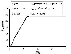
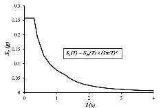
This paper introduces the elastic response spectrum models for rock sites for different parts of Malaysia for incorporation into the draft of National Annex to Eurocode 8. Both distant and local seismic hazards have been taken into account in the development of the elastic response spectra by the use of a hybrid modelling approach. The design peak ground acceleration (PGA) on rock sites is 0.1g for Peninsular Malaysia and Sarawak and 0.18g for Sabah bench marked on a return period (RP) of 2,475 years; this corresponds to reference PGA values (for notional 475 years RP being two-thirds of the design values for 2,475 years) of 0.07g and 0.12g respectively.
KEYWORDS
National Annex to Eurocode 8, Seismic Design Actions, Peninsular Malaysia, Sarawak and Sabah.
INTRODUCTION
Like other companion papers published in this issue of JURUTERA, the purpose of this paper is to outline and explain proposed key features in the planned National Annex (NA) to Eurocode 8 (EC8) for Malaysia (MS EN1998): Design Of structures For Earthquake Resistance – Part 1: General rules, seismic actions and rules for buildings. This paper was authored by members of the study group formed to undertake seismic hazard study for different parts of Malaysia and to guide the drafting of the NA.
In view of the range of peak ground acceleration (PGA) values being too narrow to justify the use of a contour map, separate response spectrum models for rock sites have been developed for Peninsular Malaysia, Sarawak and Sabah. The model proposed for the peninsula is a composite model which encapsulates results from the probabilistic seismic hazard assessment (PSHA) of recorded regional earthquakes as well as from the predictions of the local earthquakes, based on broad source zone modelling in accordance with global seismicity data. This approach best capitalises on the benefits of abundant data of distant events, while obtaining robust estimates of locally generated hazards.
Details of the modelling methodology have been published internationally (Lam et al., 2009 & 2015; Looi et al., 2015; Hee et al., 2015) and presented at a recent IEM workshop and short course (Lam, 2015; Lam et al., 2014; Looi et al., 2014) and summarised in JURUTERA (Hee, 2015). All the models introduced in this paper for rock site conditions, are to be combined with the site amplification model to be introduced in the companion paper in Tsang et al., (2016) for defining the design seismic actions on a building for given site conditions, and in Lam et al., (2016) for importance class and its behaviour factor (q).
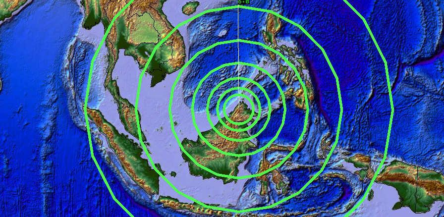
Peninsular Malaysia is subjected to a combination of earthquake hazards generated from different sources,
including the Sunda Arc subduction fault source off-shore of Sumatra, the strike-slip fault source on the island of Sumatra and local fault sources from within the peninsula. Most seismological studies and hazard modelling undertaken to date, are based on ground motions generated from distant fault sources, mainly because of their high representation in the strong motion database (Balendra et al., 2002; Balendra, 2008; Lam et al., 2009; Megawati & Pan, 2010; Megawati et al., 2005; Pan & Megawati, 2002; Pan et al., 2007; Petersen et al., 2004; Pappin et al., 2011).
While potential hazards generated locally can be significant, little is known of seismic activities within the peninsula. So, results generated from conventional PSHA and the associated use of empirical data is considered not sufficiently robust and may result in the level of hazard being underrated. In view of this unique pattern of combined seismicity, a hybrid modelling approach has been adopted to take into account both the regional and local seismic hazards. This approach was endorsed by both international and local participants in IEM workshops in April 2013 and July 2014 (Lam et al., 2014; Looi et al., 2014; Hee, 2015).
With the lack of data for local earthquakes, the major challenge is in the development of the local component of the hybrid model. There is very low frequency of occurrence of intraplate earthquakes in the Sunda Plate. Developing a reliable model based on these low quantities of occurrence data, is not statistically practicable or robust. Since there is still seismic activity, these activities inside the Plate are still comparable globally to areas with enough statistical data of intraplate events. Hence the collection of intraplate records globally from different parts of the world with similar tectonic settings, to develop a model of the rate of occurrence was adopted (Lam et al., 2015). Seismic actions to be considered for ordinary (Type II) buildings, which are defined herein as “reference seismic actions”, are based on a notional 475year return period (RP) being scaled by a factor of 2/3 of the benchmarked 2,475 year RP earthquake action. The reference PGA value is accordingly 0.07g whereas the design peak ground acceleration value for important (Type IV) built facilities is 0.1g (Lam et al., 2016). Refer to Figures 1a
& 1b for response spectrum model for rock sites presented in the displacement and acceleration formats in Peninsular Malaysia to encapsulate both distant and local hazards for 2,475 year RP.
(a) Displacement Response Spectrum
(b) Acceleration Response Spectrum
(a) Displacement Response Spectrum
(b) Acceleration Response Spectrum
(a) Displacement Response Spectrum
(b) Acceleration Response Spectrum
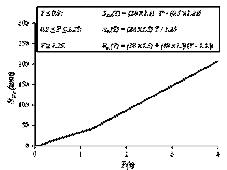
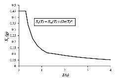
3: Elastic Response Spectrum on rock for Sabah for Type IV lifeline facilities (Design PGA = 0.18g, RP = 2,475 years)
Sarawak is also subject to distant seismic hazard from the KelawitFaultandtheBukitMersingFaultsome500kmfromthe capital of Kuching, but ground motions predicted from these identified fault sources are not as critical as the background hazards. Consequently, the response spectrum model for Sarawak was essentially based on the considerations of local hazards only. Refer to Figures 2a & 2b for the seismic action model for rock sites in Sarawak, presented in the displacement and acceleration formats. The values of PGA for the notional 475 year RP and the benchmarked 2,475 year RP are 0.07g and 0.1g respectively, as for Peninsular Malaysia but differs in the higher period range (> 1.25s), due to different frequency of occurrence of regional seismicity. Unlike Sarawak and Peninsular Malaysia, Sabah is closer to areas of higher seismicity. Many fault zones and their focal mechanisms were identified, namely Belait Fault zone, Jerudong Fault zone and Mulu Fault zone in the southwest near Brunei, Crocker Fault zone and Mensaban Fault zone which lies in the vicinity of Ranau and Kota Kinabalu in the central-north, Labuk Bay-Sandakan Basin zone near Sandakan, Pegasus Tectonic Line near Lahad Datu and the Semporna Fault in the Dent-Semporna Peninsula Zone (JMM and MOSTI, 2009).
So, the response spectrum model for Sabah is essentially based on results generated from conventional PSHA based on recorded seismicity data. Refer to Figures 3a & 3b for the seismic action model for rock sites in Sabah, presented in the displacement and acceleration formats. The values of PGA for the notional 475 year RP and the benchmarked 2,475 year RP are 0.12g and 0.18g respectively.
Separate elastic response spectrum models have been presented for rock sites in Peninsular Malaysia, Sarawak and


Our Strength is Your Confidence
APPLICATION
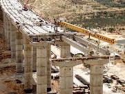
Bridge Abutment
Land Reclaimation
Housing Development & Temporary Embankment
Other Civil Engineering Application


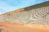
The Most Reliable & Cost Effective Retaining Wall System
APPLICATION
Slope Protection Embankment Stabilization
Housing & Road Project Other Civil Engineering Application

For enquiry please contact : CRIB TECHNOLOGIES SDN BHD (564096-A), ARE WALL (M) SDN BHD (542608-W) 46-A, SS 22/25, Damansara Jaya, 47400 Petaling Jaya, Malaysia Tel: +603-7731 7391 Fax: +603-7725 7868
Email: groadesb@yahoo.com Website: http://www.ctsbare.com
Sabah. The response spectrum model proposed for the peninsula makes use of the hybrid modelling approach which takes into account both regional and local seismic hazards.
ACKNOWLEDGEMENTS
We acknowledge the continuous support from IEM in the facilitation of the many workshops and meetings over the years, culminating in the drafting of the National Annex. We also acknowledge the intellectual input by E.P. Lim, Ahmed Zuhal Zaeem and other active participants from EC8 TC.
Notations
SDe(T) elastic displacement response spectrum spectrum
Se(T) elastic horizontal ground acceleration response
T vibration period of a linear single degree of freedom system q behaviour factor.
[1] Balendra T., Lam N.T.K., Wilson J.L., Kong K.H. (2002). Analysis of long-distance tremors and base shear demand for buildings for Singapore. Engineering Structures 24, 99-108.
[2] Balendra T., Li Z. (2008). Seismic Hazard of Singapore and Malaysia. EJSE Special Issue: Earthquake Engineering in the low and moderate seismic regions of SEA and Australia.
[3] CEN (2004) EN 1998 1. 2004. Eurocode 8: Design of Structures for Earthquake Resistance – Part 1: General Rules, Seismic Actions and Rules for Buildings. European Committee for Standardisation, Brussells.
[4] Hee, M.C. (2015). Preview of National Annex to EC8: Seismic Loadings for Peninsular Malaysia, Sabah and Sarawak”, JURUTERA (the monthly bulletin of the Institution of Engineers, Malaysia). September Issue. 32-35.
[5] Hee, M.C., Lam, N.T.K., Tsang, H.H., Looi, D.T.W. (2015). Draft National Annex to Eurocode 8 for Malaysia and cost implication for residential buildings with thin size elements. Proceedings of the 10th Pacific Conference on Earthquake Engineering, 6 - 8 November 2015, Sydney, Australia.
[6] JMM and MOSTI (2009). Final report on seismic and tsunami hazards and risks study in Malaysia. Academy of Sciences Malaysia.
[7] Lam, N.T.K. (2015). Earthquake Environment Surrounding Different parts of Malaysia. Lecture notes on How to utilise our proposed EC8 Malaysia NA for our practising consulting engineers, IEM professional short course, 29 – 30 September 2015, Armada Hotel Petaling Jaya, Malaysia.
[8] Lam, N.T.K., Tsang, H.H., Wilson, J.L., Looi, D.T.W., Hee, M.C. (2016). Performance criteria and design parameters. JURUTERA (the monthly bulletin of the Institution of Engineers, Malaysia). January Issue.
[9] Lam, N.T.K., Tsang, H.H., Lumantarna, E., Wilson, J.L. (2015). Local intraplate earthquakes considerations for Singapore. Institution of Engineering Singapore Part A: Civil & Structural Engineering. Published on line 21 November 2014. (In press)
[10] Lam, N.T.K., Tsang, H.H., Lumantarna, E., Wilson, J.L. (2014). Background Seismicity of Local Intraplate Earthquakes. Proceedings of presentation at 2 day workshop on recommended earthquake loading model in the propose N.A. to EC8 for Sabah, Sarawak & updated model for Peninsular Malaysia, 16 – 17 July 2014, Armada Hotel Petaling Jaya, Malaysia.
[11] Lam, N.T.K., Balendra, T., Wilson, J.L., Srikanth, V. (2009), Seismic Load Estimates of Distant Subduction Earthquakes Affecting Singapore, Engineering Structures, 31(5): 1230-1240.
[12] Looi, D.T.W., Hee, M.C., Tsang, H.H., Lam, N.T.K. (2014). Updated Design Spectrum for Peninsular Malaysia. Proceedings of presentation at 2 day workshop on recommended earthquake loading model in the propose N.A. to EC8 for Sabah, Sarawak & updated model for Peninsular Malaysia, 16 – 17 July 2014, Armada Hotel Petaling Jaya, Malaysia.
[13] Looi, D.T.W., Lam, N.T.K., Tsang, H.H., Hee, M.C. (2015). Seismic analysis in the low to moderate seismicity region of Malaysia based on the draft handbook. Proceedings of the 10th Pacific Conference on Earthquake Engineering, 6 - 8 November 2015, Sydney, Australia.
[14] Megawati K., Pan T.C. (2010). Ground-motion attenuation relationship for the Sumatran megathrust earthquakes. Earthquake Engineering and Structural Dynamics 39, 827-845.
[15] Megawati K., Pan T.C., Koketsu K. (2005). Response spectral attenuation relationships for Sumatran-subduction earthquakes and the seismic hazard implication to Singapore and Kuala Lumpur. Soil Dynamics and Earthquakes Engineering 25, 11-25.
[16] Pan T.C., Megawati K. (2002). Estimation of PGA of the Malay Peninsula due to Distant Sumatra Earthquakes. Bulletin of the Seismological Society of America 92:3, 1082-1094.
[17] Pan T.C., Megawati K., Lim C.L. (2007). Seismic shaking in Singapore due to past Sumatran earthquakes. Journal of Earthquake and Tsunami 1:1, 49-70.
[18] Pappin J.W., Yim P.H.I., Koo C.H.R (October 2011). An approach for seismic design in Malaysia following the principles of Eurocode 8. IEM Jurutera Magazine, 22-28.
[19] Petersen M.D., Dewey J., Hartzell S., Mueller C., Harmsen S., Frankel A.D., Rukstales K. (2004). Probabilistic seismic hazard analysis for Sumatra, Indonesia and across the Southern Malaysian Peninsula. Tectonophysics 390, 141-158.
[20] Tsang, H.H., Lam, N.T.K., Looi, D.T.W., Wilson, J.L., Hee, M.C. (2016). Site Classification and Response Spectrum Model for Soil Sites. JURUTERA (the monthly bulletin of the Institution of Engineers, Malaysia). January Issue.

This paper introduces the elastic response spectrum models for different ground conditions, with a particular emphasis on the phenomenon of periodic ground shaking in lexible soil sites. The natural period of the site, which is closely correlated with the depth of the soil sediments, has been incorporated as a parameter in the construction of the soil response spectrum.
This model, to be introduced in the draft National Annex (NA) to Eurocode 8 (EC8) for Malaysia, resembles real behaviour much better than the response spectrum models stipulated by EC8 itself. The need to address the effects of site periodicity is particularly justified in regions of low-to-moderate seismicity such as Malaysia, where structures are typically of limited ductility and so, are vulnerable to the elastic amplification phenomenon as described in the paper.
Soil modification of seismic waves within soil sedimentary layers overlying bedrock can have significant effects on both their amplitude and frequency properties. Multiple reflected seismic waves that are trapped within the soil layers are periodic in nature as a result of filtering and wave super position. The deeper the soil layers, the longer it takes for the reflected wave front to travel through the soil medium. Thus, the natural period of the site is controlled by the thickness of the soil layers.
The extent of soil amplification also depends on the level of shaking, the properties of the soil materials (including its shear modulus and plasticity) and the shear modulus of the underlying bedrock materials. Amplification of the response of structures to periodic excitation is very selective in nature, in that the effects are only pronounced in structures of a certain period range. In conditions of severe ground shaking, site amplification associated with the periodic motions can be suppressed by energy dissipation in an in elastically responding ductile structure and in the soil medium itself. Thus, its effects have not been explicitly parameterised in major codes of practices that were derived from research and experiences in regions of high seismicity. The issue of periodicity has much greater design implications in regions of low-to-moderate seismicity such as Malaysia, where structures are typically of limited ductility and motions in the soil are not as intensive, as the amount of energy dissipation is much less than that in regions of high seismicity.
Site effects can be conveniently observed on response spectra. In situations where a distinct soil-rock interface exists, the amplification ratio usually has a maximum value close to the natural period of the soil layer (TS). Figure 1 is a good example of amplification driven by soil site periodicity; it shows the acceleration
on rock and soil sites at Oakland Outer Harbour in the 1989 earthquake at Loma Prieta, California, United States (Dickenson et al., 1991). In the draft NA to EC8 for Malaysia, the site natural period (TS) is incorporated as a parameter in the construction of the response spectrum for structures.

Thespectralaccelerationvaluesareafewtimeslargeron asoilsiteincomparisonwitharocksite,whiletheamplification ratio is in the order of four times for the peaks at 0.7s. Such significant and selective amplification phenomenon has to be taken into account in the construction of the response spectrum as per design code of practices
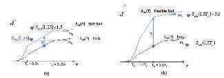
EC8 recommends two types of elastic response spectrum: Type 1 for high seismicity areas and Type 2 for less active areas. The spectral shapes mimick the spectral shapes of large (M = 7~7.5) and small (M = 5.5) magnitude events occurring at a site-source distance of 10km, which will in effect, result in different sets of corner periods. However, it is stated clearly in EC8, Part 1: Clause 3.2.2.2 (2)P that suitable values of corner periods could be investigated and specified in the NA of a country and that it is not necessary to stick to the use of either Type 1 or Type 2 response spectrum. Although the importance of the total thickness of soil layer is well recognised, site classification nowadays is based solely on the properties to a certain fixed depth of nearsurface materials. In EC8, a site shall be classified according to the value of the average shear wave velocity (SWV) (Vs,30), or the value of Standard Penetration Resistance Test (SPT) – N (for cohesion-less soil), or the value of undrained shear strength cu (for cohesive soil), over the upper 30m.
A site shall be classified as either Site Class A, B, C, D, E, S1 or S2 based on site soil properties. Profiles containing distinctly different soil and/or rock layers shall be subdivided into those layers designated by a number from 1 to n at the bottom where there are a total of n distinct layers in the upper 30m. The symbol i then refers to any one of the layers between 1 and n. The average shear wave velocity Vs,30 can be computed by Equation (1). The same equation also applies to the computation of the values of SPT–N and undrained shear strength.

where Vs,i = The shear wave velocity in m/s; di = The thickness of any layer between 0 and 30m.
A uniform soil factor, S, shall be applied across the whole response spectrum for each site class (ground type), which is up to 1.4 (for Type 1) and 1.8 (for Type 2). The first corner period TC varies between 0.4 s to 0.8s (for Type 1) and between 0.25s to 0.3s (for Type 2) elastic response spectrum. Larger values of TC essentially translate to a higher demand at the intermediate-to-long-period range. TD is fixed at 2.0s (for Type 1) or 1.2s (for Type 2). Noted that TC is the first corner period at the upper limit of the constant spectral acceleration region of the elastic response spectrum model, whilst TD is the second corner period at the beginning (lower limit) of the constant spectral displacement region.
In the proposed scheme, a site shall be characterised by the weighted average initial SWV (VS), depths of soils (HS) and the initial low-amplitude natural period (TS) of all the soil layers down to the depth of very stiff sedimentary materials or bedrock. This site-period approach recognises that deep deposits of stiff or dense soils exhibit high-period site response characteristics not shown by deposits of only a few 10s of metres of the same material.
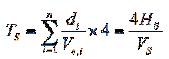
The value of TS can be estimated based on geophysical (or geotechnical) measurements, with the use of Equation (2). It can be computed based on four times the shear-wave travel-time through materials from the surface to underlying stiff sediments or bedrock, if the thickness (di) and initial SWV (Vs,i) of the individual soil layers are known. Alternatively, the value of TS can be expressed in terms of the total thickness of the soil layers (HS) and its weighted average SWV (VS).
In the proposed site classification scheme, a site with TS < 0.15s, where the soil layers are very thin and/or stiff, the site can be classified as a rock site (equivalent to the original ground type A in EC8). The elastic response spectra for rock sites for the three regions have already been fully discussed in a companion article (Lam et al., 2016a).
The site amplification for such very thin and/or stiff ground would mainly concern structures with a natural period lower
than 0.2s, while the amplification for a natural period higher than 0.2s is minimal. It is note worthy that the corresponding peak displacement demand for such low period structures is very small in regions of low-to-moderate seismicity. Most structures that are not brittle, would be capable of sustaining this very minor peak displacement demand without being subjected to any significant risks of collapse.
A site with TS between 0.15s and 0.5s is classified as a stiff soil site (which combines the original ground type B and C in EC8, for simplicity and practicality). When the site natural period TS is greater than 0.5s, the site can be considered as flexible soil site. However, for TS > 1.0s, or deposits consisting of at least 10m thick of clays/silts with a high plasticity index (PI > 50), dynamic site response analyses shall be performed or Type 1 elastic response spectrum for ground type D shall be adopted. A soil column with TS > 1.0s is considered very flexible and there may be significant higher modes effects in the site response behaviours. For deposits of 10m thick (or more) of clays/silts with a high plasticity index (PI > 50), special consideration should be taken, as exceptionally high amplification can happen.
The proposed site classification scheme is presented in Table 1. This scheme was designed for simplicity, which is more suitable for application in regions of low-to-moderate seismicity, and for using site natural period as the sole parameter for site classification. More features of the response spectrum model for each site will be discussed in a later section.
Table 1: Proposed site classiication scheme
* For TS > 1.0 s, or deposits of at least 10m thick of clays/silts with a high plasticity index (PI > 50), dynamic site response analyses shall be performed or Type 1 elastic response spectrum for ground type D shall be adopted.
The Elastic Response Spectrum model can be constructed using Equation (3) in the displacement (RSD) format, as expressed in terms of four spectral parameters, SD (TD), TC, TD and m. The emphasis on the prediction of the value of RSD is to align with displacement-based seismic design methodology.
The elastic response spectrum model in the acceleration (RSA) format can be conveniently obtained by direct transformationfromthedisplacementformatusingEquation(4).
This response spectrum format is nearly identical to that currently adopted in EC8 and is similar in form to those
adopted in various codes of practice worldwide. The only difference is at the constant-displacement range, where a linear function has been proposed for reflecting the unique seismicity pattern of the region.
For rock (R) sites, SD(TD) is the region-specific spectral displacement on rock SDR(T ) at T = 1.25s. This value is 16mm (24mm) for Peninsular Malaysia and Sarawak, and 28mm (42mm) for Sabah, for a notional return period of 475 years (values in parenthesis for return period of 2,475 years).
For stiff soil (SS) sites, a uniform S-factor of 1.5 shall be applied across the whole response spectrum on rock. This recommendation is consistent with that for ground type D of EC8 Type 2 spectrum (for regions of low-to-moderate seismicity). The values of the two corner periods TC and TD are taken as the same as that for rock sites, which are equal to 0.3s and 1.25s respectively. TB is fixed as 0.1s for all ground types in the proposed scheme. However, it is noted that the form of the response spectrum in the NA has not explicitly indicated TB as it is undesirable in practice, given uncertainties in the value of the natural period of vibration of the structure.
For flexible soil (FS) sites, a response spectrum model that takes into account resonant-like amplification phenomenon is proposed (Lam et al., 2001; Tsang et al., 2006a; Tsang et al., 2006b; Tsang et al., 2013; Tsang et al., 2015). SD(TD), TC and TD, shall be computed using Equations (5)-(7): where SDR (1.5TS) is the response spectral displacement (RSD) on rock at T = 1.5TS
(7)
Response spectral velocity (RSV) of a soil spectrum typically peaks between 1.2TS and 1.5TS (Tsang et al., 2006b), with respect to the level of ground shakings in regions of lowto-moderate seismicity. S is the site amplification factor of 3.6 (Tsang et al., 2006a), which is applied at the constantvelocity range (intermediate period range). For example, the equivalent amplification ratio at T = 1.0s ranges from 2.5 to 5.9 in other major codes of practice (including EC8, International Building Code, Australian Standard and New Zealand Standard). In fact, the largest amplification ratio at the low-period range would be 1.8, which is consistent with that for ground type D of EC8 Type 2 spectrum.
Table 2 shows a summary of the proposed models for all site classes. Table 3 summarises the key regional-dependent hazard parameters. Importance factor γI should be referred to another companion paper (i.e. Lam et al., 2016b). The parameters slope mR and mF are aimed at capturing the long period spectral shape of distant events. Figure 2 shows a schematic diagram of the proposed response spectrum models for the three ground types (in RSD format). The model has been well validated through comparison with results obtained from computational site response analysis of soil columns derived from real borehole records, as well as from strong motion data recorded in the Northridge earthquake, 1994.
* For TS > 1.0 s, or deposits consisting of at least 10m thick of clays/silts with a high plasticity index (PI > 50), dynamic site response analyses shall be performed or Type 1 elastic response spectrum for ground type D shall be adopted.
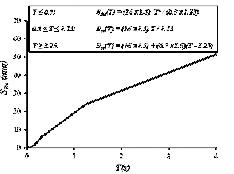
In order to demonstrate the proposed model for incorporation into the draft NA for flexible soil (FS) sites, a typical engineering borehole record was taken from a soil site in Peninsular Malaysia as example (See Figure 3). For clarity, Table 4 shows the SPT-N values for individual soil layers. It is noted that the computation of equivalent values of N > 50 for certain soil layers is above the normally considered “saturated limit” of 50 (e.g. at depth of 33m, N = 50 with a penetration depth P = 270mm; the equivalent N should be calculated as 50x300/270 = 55.6).
In view of the lack of local studies, empirical formulas that are applicable to all types of soils as summarised in Wair et al., 2012 were referenced. Table 4 also shows computations of SWV values and the corresponding SPT–N values based on two empirical formulas that are applicable to all types of soils (i.e., Imai and Tonouchi, 1982 and Sisman, 1995). The individual soil layers thickness (di) over initial SWV (Vs,i) ratio were calculated to obtain the weighted average SWV (VS) by the use of Eq. (1). In this case, VS = 42/0.19 = 221 m/s. The value of TS can be expressed in terms of the total thickness of the soil layers (HS) and its weighted average SWV (VS) via the use of Eq. (2), TS = 4 x 42/221 ≈ 0.7s, which falls in between 0.5s and 1.0s, and is categorised as FS (as in Table 2).
Based on the spectral parameters in Tables 2 and 3, the following calculations show steps for construction of the response spectrum for this FS site in Peninsular Malaysia for a notional 475 years return period (γI = 1):

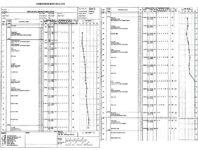
Table 4: Computation of site natural period TS
NOTE: the Malaysia EC8 NA suggested that sedimentary layers with SPT-N value greater than 100 can be omitted in the computations of site natural period and weighted average SWV; nonetheless more layers of soil after SPT-N 100 can be included for calculation as shown in Table 4.
Step 2: Calculate SDR (TD) on rock according to Equation (3) and Table 3: For rock site, TC = 0.3s and TD = 1.25s, hence
DR(
Step 3: Calculate SD (TD) on soil according to Equation (5)
SD (TD) = SDR (1.5 TS) x S = 13.44 x 3.6 = 48.38mm
Step 4: Calculate the whole range of SDe (T) on soil according to Equation (3); corner periods are shown in detail and summarised in Table 5
T ≤ 0.84s: SDe (T ) = 48.38 [T2 / (0.84 x 1.05)]
0.84s ≤ T ≤ 1.05s: SDe (T ) = 48.38 (T / 1.05)
1.05s ≤ T ≤ 4s: SDe (T ) = 48.38 + 0 (T – 1.05), where m = mF = 0
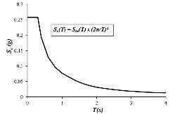
Step 5: Transformation into acceleration (RSA) format in unit of g from the displacement (RSD) format using Equation (4), both of which are shown in detail and summarised in Table 5
T ≤ 0.84s: Se (T ) = 48.38 [T2 / (0.84 x 1.05)] x (2π / T)2 / 9810
0.84s ≤ T ≤ 1.05s: Se (T ) = 48.38 (T / 1.05) x (2π / T)2 / 9810
1.05s ≤ T ≤ 4s: Se (T ) = [48.38 + 0 (T – 1.05)] x (2π / T)2 / 9810
The elastic response spectrum constructed in accordance with the proposed model as per the draft NA for a flexible soil (FS) site with TS = 0.7s (in the range of 0.5 s to 1.0 s) is shown in Figure 4, along with that stipulated by EC8 for Class D and E sites of Type 1 and Type 2 spectra. Both soil spectra are based on a common spectrum for rock, which is based on notional peak ground acceleration of 0.1g (2,475 years return period) in Peninsular Malaysia. The selective nature of response spectral amplification on a flexible soil layer is well reflected in the shape of the proposed soil spectrum. Whilst the amount of amplification of the proposed RS in the higher period range falls in between Type 1 and Type 2 model of EC8, the proposed model is not as conservative in the short period range. In summary, the proposed RS model resembles real behaviour of elastically responding structures much better than that of the existing EC8 model.
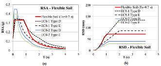
Vertical action is particularly important for near fault ground motion which is the design earthquake scenarios in higher seismicity regions. Nonetheless, provisions for vertical earthquake actions as per recommendations by EC8 are introduced, whilst the ratio of avg/ag is taken as 0.7 based on the recent research findings reported by Elgamal and He (2004). Given that the design horizontal action in Malaysia is generally low it is of the opinion of the NA drafting team that vertical action would not be the controlling factor in the design of most building structures. It is also noted that horizontal ground motion is amplified much more than vertical ground motion on soil sites.
A set of elastic response spectrum models for various ground conditions is to be incorporated into the NA to EC8 for Malaysia to replace the original provisions in EC8. Central to the construction of the response spectrum is the site natural period (TS) which is to be estimated using relationships presented in the paper. The selective nature of response spectral amplification on a flexible soil layer is well reflected in the shape of the proposed soil spectrum which resembles real behaviour much better than the response spectrum models stipulated by EC8 itself.
Notations
HS depths of soils
N SPT values

S soil factor
SD(TD) region-specific spectral displacement on rock
SDe(T) elastic displacement response spectrum
SDR(T) elastic displacement response spectrum on rock
Se(T) elastic horizontal ground acceleration response
T vibration period of a linear single degree of freedom system
TB lower limit of the period of the constant spectral acceleration branch
TC first corner period
TD second corner period
TS initial low-amplitude site natural period (note: this symbol is different from EC8 whereTsisreferredasthedurationofthestationarypartoftheseismicmotion)
VS weighted average initial shear wave velocity
Vs,i shear wave velocity of individual soil layer
Vs,30 average value of propagation velocity of S waves in the upper 30 m of the soil profile
ag notional design peak ground acceleration on rock
avg design ground acceleration in the vertical direction
d thickness of any layer between 0 and 30 m
m slope parameter to capture long period spectral shape of distant events
mF slope parameter on flexible soil
mR slope parameter on rock
q behaviour factor
γI importance factor
ACKNOWLEDGEMENTS
We acknowledge the continuous support from IEM in the facilitation of the many workshops and meetings over the years, culminating in the drafting of the National Annex. We also acknowledge the intellectual input from E.P. Lim, Ahmed Zuhal Zaeem and other active participants from EC8 TC.
[1] Australian Standard:AS 1170.4-2007, Structural DesignActions, Part 4: EarthquakeActions inAustralia. Sydney, Australia: Standards Australia; 2007.
[2] Dickenson S.E., Seed R.B., Lysmer J., Mok C.M. (1991). Response of soft soils during the 1989 Loma Prieta earthquake and implications for seismic design criteria, Proceedings of the 4th Pacific Conference on Earthquake Engineering, Vol. 3, pp. 191-204, New Zealand National Society for Earthquake Engineering, Auckland, New Zealand, 20-23 November, 1991.
[3] Elgamal A., and He L. (2004). Vertical earthquake ground motion records: an overview. Journal of Earthquake Engineering 8: 663-697.
[4] EN 1998-1:2004, Eurocode 8: Design of Structures for Earthquake Resistance – Part 1: General Rules, Seismic Actions and Rules for Buildings. United Kingdom: European Committee for Standardisation; 2004.
[5] Imai T., and Tonouchi K. (1982). Correlation of N value with S-wave velocity and shear modulus. In: Proc. of the 2nd European Symp. on Penetration Testing, Amsterdam, 67–72.
[6] International Building Code (IBC). Country Club Hill, Illinois, USA: International Code Council; 2012.
[7] Lam N.T.K., Wilson J.L., Chandler A.M. (2001). Seismic displacement response spectrum estimated from the frame analogy soil amplification model. Engineering Structures 23: 1437-1452.
[8] Lam, N.T.K., Tsang, H.H., Looi, D.T.W., Wilson, J.L., Hee, M.C. (2016a). Design response spectrum models for rock sites. JURUTERA (the monthly bulletin of the Institution of Engineers, Malaysia). January Issue
[9] Lam, N.T.K., Tsang, H.H., Wilson, J.L., Looi, D.T.W., Hee, M.C. (2016b). Performance criteria and design parameters. JURUTERA (the monthly bulletin of the Institution of Engineers, Malaysia). January Issue.
[10] New Zealand Standard: NZS 1170.5:2004, Structural Design Actions Part 5: Earthquake Actions – New Zealand. Wellington, New Zealand: Standards New Zealand; 2004.
[11] Sisman H. (1995). An Investigation on Relationships between Shear Wave Velocity, and SPT and Pressuremeter Test Results. Master of Science Thesis, Ankara University, Turkey.
[12] Tsang H.H., Chandler A.M., Lam N.T.K. (2006a). Estimating non-linear site response by single period approximation. Earthquake Engineering and Structural Dynamics;35(9):1053-1076.
[13] Tsang H.H., Chandler A.M., Lam N.T.K. (2006b). Simple models for estimating period-shift and damping in soil. Earthquake Engineering and Structural Dynamics;35(15):1925-1947.
[14] Tsang H.H., Lam N.T.K, Wilson J.L. (2013). A displacement based soil amplification model for low and moderate seismicity regions. Proceedings of the IStructE Conference on Structural Engineering in Hazard Mitigation, Beijing, China, October 28-29, 2013.
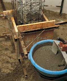


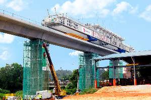
[15] Tsang H.H., Wilson J.L., Lam N.T.K. (2015). Recommended Site Classification Scheme and Design Spectrum Model for Regions of Lower Seismicity. Proceedings of the Pacific Conference on Earthquake Engineering, Sydney, Australia, November 6-8, 2015.
[16] Wair B.R., DeJong J.T., Shantz T. (2012). Guidelines for Estimation of Shear Wave Velocity Profiles, PEER Report 2012/08.

The ENDUROFRAME® building system is proving to be a smart, simple solution for builders, manufacturers and developers

Think about this: Design your building in software, get the design printed by a special machine and have the parts installed and assembled on site. With that, the building business has just become easier for builders, manufacturers and developers.
It does sound like a 3D printing system that is doing the job but ENDUROFRAME® buildingsystemBusiness Manager Paul Jones from Australia described it as a “digital fabrication”.
“The key thing about the ENDUROFRAME® building system is about digital fabrication. The entire building can be built in a computer.
“We are able to model, detail and engineer a building, to see exactly what it looks like and whether the building fits with other elements such as the mechanical and electrical features as well as the architecture.
“All these can be checked before the digital file is downloaded into the roll former, which is similar to a 3D printer, to literally print out a house.” Jones explained.
He added that the ENDUROFRAME® building system “pretty much” provides all the features that a builder or developer needs to build a light gauge steel building.
Essentially, it is a light gauge framing system, made from steel of between 0.5mm and 1.2mm thick, manufactured by a special machine called the ENDURO® rollformer.
Jones said that as the building system consists of elements such as wall frames,
roof trusses and floor trusses, the building system is thus a combination of finished building system that can be used to design, detail and manufacture steel frames for residential and commercial structures, adding that the company has customers who are using the ENDUROFRAME® building system for lost formwork and curtain wall applications as well.
The ENDUROFRAME® business was set up about four years ago in Australia to bring together all BlueScope’s intellectual property in steel framing. This includes ways to build with light gauge steel frames, especially in developing smart software, installation and manufacturing of steel frames.
One of the main components of the ENDUROFRAME® building system is the smart software system called ENDUROCADD®. It is a brain child of more than 20 years of light gauge steel research and development conducted byBlueScopeandconstructionfeedback from thousands of past projects.
Described as the core of the ENDUROFRAME® building system, it is smart and versatile, thanks to the power of the digital age.
“It’s smart because it’s all about technology. We believe that one of the big movements that is happening around the world at the moment is the shift towards digital fabrication.
“You could have an architect and builder in Malaysia, someone doing the designofthecomponentsinAustraliaand an engineer in the United States. And it is allaboutshiftingarounddigitalfiles.
“You could have collaborations from many people in different locations to get the building correct,”Jones explained.
Unlike design software which is available in the market today, the ENDUROCADD® software system is said to be easy to work with. A specialist with CAD skills is not required to operate the software – all that is needed is the building skills of the user.
In terms of its versatility, Jones said the software system is a tool to help users to
design light gauge steel frames but there are companies which are using it for various purposes that are beyond what the ENDUROFRAME® building system was originally intended for.
“For example, we have a licensee in Malaysia that is using our system in a lost formwork application and it is something that we have never originally designed thesystemfor.Wesoldthebuildingsystem to a Melbourne-based company that intendstouseitforafacadeapplication. We also have companies that bought the building system for making modular buildings.
“Again, this is something we did not originally foresee. In the hands of engineers, it has many areas that can be used and explored,” he shared.
The ENDUROCADD® software system also offers features such as curved roofs and walls in both plan and elevation views – by making them in small and short segments.
In addition, the ENDUROCADD® software system and its associated design manuals are helpful resources for users because these are based on hundreds of hours of testing to confirm their performance.
Furthermore, various trainings are provided locally through NS BlueScope Malaysia Sdn. Bhd. and one of them is how to use the software by drawing on experiences from other countries. It includes demonstrations on how the ENDUROFRAME® building system can be used in low-rise, mid-rise and multistorey buildings, in addition to providing assistance to support the machines (ENDURO® rollformer) that manufacture the frames.
Jones believes that this is an essential step to ensure that the machines are running efficiently, working productively and able to manufacture as many products as possible.
The ENDUROCADD® software system can also create strong, reliable truss designs which are self-certified by the software for non-cyclonic regions such as Malaysia. It is the only steel framing software that is entirely self-certified and audited in accordance with the ABCB Protocol for Structural Software.
For manufacturing steel frames, Jones said the steel frames for all parts required for a building frame manufactured from the ENDURO® rollformer machine at high speed to half a millimetre to accuracy.
For its operation, the ENDURO® rollformer machine requires only one person to operate it.
Besides being smart, the ENDUROFRAME® steel frames are also easy to fit together. With the use of the ENDUROWALL® framing system, a light weight wall framing system that has prepunched holes and recessed dimples, the builders need only relatively unskilled workerstofittheentirestructuretogether. This also applies to the use of the ENDUROTRUSS® framing system where only little re-skilling is required to detail or installit.Theultimateroofframingsolution is designed to work similarly to timber trusses and it is hassle-free.
It is entirely “self-jigging” with the fixing frame from one side and it uses a combination of industry standard timber frame bracketry and brackets which are manufactured by the ENDURO® rollformer.
The ENDUROTRUSS® framing system features a wide range of truss designs which are easily suited to the designs of alltypesofhouses.Theyarealsomadein accurate dimensions.
With the flexibility of such framing system, they can be factory assembled or installed on site.
MALAYSIA A VIABLE MARKET
Jones believes that Malaysia is a great market for the ENDUROFRAME® building system and is a perfect solution to the local housing issues.
“With the government looking forward to build 500,000 houses over the next five years and effectively doubling the number of houses that need to be built each year, the ENDUROFRAME® building system is the perfect solution to achieve that.
“They need a quicker and more efficient solution and I think the ENDUROFRAME® building system is perfectly suited for these opportunities.”
With the wave of building more homes starting to come through, he opined that it will be a great opportunity for the building system.
“We currently have three licensees in Malaysia and soon we will have the fourth. They are located in the north of Malaysia, the outskirts of Kuala Lumpur and in Sarawak. Soon, we will have one in Sabah.
“So we do have a good area coverage and this will also enable us to work with the licensees which we will
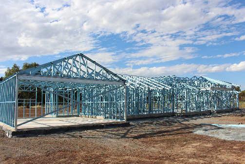

support to push the ENDUROFRAME® building system into the market,” Jones added.
Another key part of what the ENDUROFRAME® business does is that “it will supply the quality system that goes with the machines”.
Jones said, “We have quality assurancearoundthedesignchecksthat needtobedoneinthemanufactureand the assembly of the frames. These are documented and licensees are trained when the machines are installed.”
In addition to training and quality assurance checks, another key to the good quality system of the ENDUROFRAME® building system
is the complete trace ability in the manufacturing system.
“Every part produced by the ENDURO® rollformer machine has three things on it: the machine number, the manufacturing date and the raw materials that are used (it has an inkjet mark that tells us the standard that the steels are manufactured to).
“This means that we can trace it back to the individual machines, and to the quality control records, through to the design, the steel coils used, and back to the original manufacturing of the steel if there is a problem found in the steel frame that has been installed or assembled on site,”he explained.
Jones also believes that it is “almost unprecedented” to have such traceability and quality assurance that the ENDUROFRAME® building system can provide in the construction of houses.
Locally, mobile training units are also available on site to train the builders and installers to adequately equip them, in addition to maintaining the quality of the building system as well as to upskilling the workers.
“It is a similar programme available in Thailand. The mobile training units will go to the actual site and provide onsite training. It is a flexible approach in terms of reaching out to the Malaysian market,” said Alan Lee, Sales Manager at NS BlueScope Malaysia Sdn. Bhd.
For more information please visit: www.bluescope.com.my/product/ enduroframe/ enquiries@bluescope.com +603-33616888

In the proposed seismic action model to be incorporated into the National Annex (NA) to Eurocode 8 (EC8) for Malaysia, the design seismic actions for important built facilities are benchmarked on a 2,475 years return period (RP) earthquake action whereas the reference seismic action (notional 475 year RP) to be considered for ordinary buildings is the design action scaled by a factor of 2/3. Decisions leading to the proposal are explained and terminologies clariied in the paper which draws frequent references to the literature citing major codes of practices.
KEYWORDS
NationalAnnextoEurocode8,SeismicDesignActions.
INTRODUCTION
The decision on the return period of the design seismic actions and the resulting design peak ground acceleration value for buildings of different importance classes in different parts of Malaysia, is a major item of consideration to be discussed in this paper along with performance criteria for buildings of different classifications.
STRUCTURAL PERFORMANCE CRITERIA AND PARAMETERS FOR DESIGN SEISMIC ACTIONS
Performance Criteria
According to EC8 – Part 1 (CEN, 2004), building structures shall be designed and constructed in such a way that the requirements of (i) No Collapse (NC) and (ii) Damage Limitations (DL) are met. The state of No Collapse is essentially in alignment with designing to the ultimate limit state which entails the protection of life in a rare earthquake event, by ensuring that no part of the structure collapses and that adequate residual lateral resistant capacity of the structure remains after the event to withstand strong aftershocks should these occur. The safety of the occupants can be assured, but the built facility can be inhabitable or the damage can be too costly to repair.
The “no collapse”, or “no local collapse”, design criterion as described, is comparable to the “life safety” performance
criterion as defined in SEAOC Vision 2000 document (SEAOC, 1995) in the United States and the “significant damage” (SD) performance criterion stipulated in EC8 – Part 3, which contains provisions for the seismic assessment and retrofitting of existing buildings. The No Collapse performance criterion is not to be confused with the “near collapse”, or “collapse prevention”, performance criterion of SEAOC Vision 2000 which is about ensuring that the building is able to sustain sufficient vertical load carrying capacity in a very rare earthquake event when the structure is on the verge of wholesale collapse with little or no residual lateral resistance, and some falling hazards may be present (Booth, 2014; Fardis, 2009).
The Damage Limitations (DL) performance criterion, which corresponds to the service ability limit state criterion (in the conventional limit state design approach), has also been written into both Part 1 and Part 3 of EC8 and is intended to address the damaging potentials of frequent or occasional earthquake events in the design of ordinary buildings. The DL performance criterion is comparable to the “immediate occupancy”, or “operational”, performance criterion of SEAOC Vision 2000 which is to ensure no permanent drift and no loss of lateral strength and stiffness of the building structure. The built facility is then fit for continuous occupation during the recovery period and the functionality of the building will not be interrupted significantly by repair activities. In regions of low or moderate seismicity that are remote from tectonic
2. Damage Limitation Damage Limitation Operational or Immediate Occupation Nopermanentdriftandnolossoflateralstrengthorstiffnessofthebuilding.Thebuilt facility remains to be fit for continuous occupation in an occasional event.
3.(DL) Significant Damage Life Safe
4. No Collapse Near Collapse Collapse Prevention or Near Collapse
No part of the structure collapses and adequate residual lateral resistant capacity remains in the structure after a rare event to withstand strong aftershocks in order that safety of the occupants can be secured but building may be inhabitable and repair too costly.
Structure is able to sustain sufficient vertical load carrying capacity in a very rare earthquake event when the structure is at the edge of wholesale collapse. Residual lateralresistantcapacityofthebuildingmighthavebeenlost.
plate boundaries, only rare or very rare earthquake events are of concern. So, the DL performance criterion need not be checked in such an environment except for built facilities forming part of lifeline facilities in the aftermath of an earthquake disaster or buildings containing hazardous materials.
Refer to Table 1 for a summary of the performance criteria of building structures as defined by the two parts of EC8 and the SEAOC Vision 2000 document. Parameters for design seismic actions
In this section, recommendations for the value of the return period of seismic actions and PGA values for buildings of different importance classes and the behaviour factor are discussed. The return period of the considered seismic actions that are aligned with the No Collapse (NC) performance criterion, is to be decided on a country-by-country basis, given that factors governing such a decision would involve social, economic and political considerations. Thus, the return period for the NC performance criterion is to be specified in the respective NA of the country.
It is stated in the footnote attached to Clause 2.1 in EC8 – Part 1, that ground motion intensity in a rare earthquake event consistent with a 10% chance of exceedance for a design life of 50 years (i.e. return period of 475 years) is recommendedasthedesignseismicaction.Itwasnotedthatthisrecommendation was drafted in the late 1990s, at a time when it was still the norm to not consider return periods exceeding 475 years in the design of structures supporting ordinary buildings (Booth, 2014). Implicit in the NC performance criterion is that the building is expected to have sufficient additional reserve capacity to sustain a very rare, and extreme, earthquake event without experiencing wholesale collapse (Fardis, 2009).
Seismic design provisions around the world have evolved over the decades, during which time experience gained through field observations from places like California, have been taken into account in numerous code revisions. In such an environmentdominatedbyactivefaults,theintensityofgroundshakingisincreased by a factor which is slightly greater than 1.5 as the return period is increased from 475 years to 2,475 years (Tsang, 2014). Code compliant constructions that have been designed to fulfil NC performance criterion are expected to have sufficient additional reserve capacity to also fulfil collapse prevention criterion when subject to seismic actions that are 1.5 times the design level. Despite this margin of safety from collapse that is implicit in contemporary practices, major earthquake disasters in recent years, including the 1995 Kobe earthquake in Japan and the 2008 Sichuan earthquake in China, prompted a critical review of the adequacy of this long established convention of designing to a return period of 475 years (Tsang, 2011).
In regions of low or moderate seismicity (where earthquakes occur infrequently and active faults are difficult to identify), ground shaking intensity ratio that is associated with an increase in return period from 475 years to 2,475 years, can be escalated to a value much greater than 1.5. A factor varying between 2.4 and 5 is predicted for earthquakes in an intraplate environment (Tsang, 2014, Geoscience Australia, 2012). Given these predictions, building structures designed on a return period of 475 years to fulfil NC performance criterion in an intraplate environment, would not automatically possess adequate additional reserve capacity to prevent collapse in a very rare event.
The trend of moving away from the conventional practice of designing to a return period of 475 years was initiated by the influential FEMA450 document (BCCS, 2003) which was to guide the design of new buildings in the United States. The design seismic action was recommended to be based on a maximum considered earthquake (MCE) of 2,475 years, scaled down by a factor of 2/3 (reciprocal of 1.5). This scaling factor can be interpreted as the margin between the state of NC and collapse prevention of the structure in order that code compliant buildings can always be assured of the capacity to prevent collapse in a very rare earthquake event.
The 2005 edition of the National Building Code of Canada (NRCC, 2005) increased the return period from 475 years to 2,475 years without applying a scaled down factor of 2/3 (Mitchell et al., 2010) but a generous 2.5% drift limit, which was consistent with the Collapse Prevention performance criterion, was specified. The


NA to EC8 for the United Kingdom (BSI, 2008) also specified a return period of 2,475 years to override the recommendation of 475 years in EC8 – Part 1 (CEN, 2004) for designing to No Collapse (Life Safe) performance criterion, which was more stringent than requirements in Canada.
In perspective, a design return period of 2,475 years is actually not overly conservative, given that the annual fatality risk of an occupant in a building which has been designed to a return period of 2,475 years is of the order of 10-6, which is consistent with involuntary fatality risk affecting building occupants in other types of natural disasters (Tsang, 2014).
In view of the facts presented in the above design, seismic actions presented in terms of PGA values on rock sites are recommended herein for various importance classes of buildings as summarised in Table 2 for Peninsular Malaysia, Sarawak and Sabah. It is shown that all built facilities of importance class IV, including hospitals, emergency services and other lifeline facilities, are to be designed to a return period of 2,475 years to fulfil NC performance criterion in order that these facilities are safe to occupy in the aftermath of a very rare event as well as fit to continue to operate in more frequent events. Reference seismic actions to be considered in the design of ordinary buildings of importance class II in Peninsular Malaysia and Sarawak, are accordingly based on a reference PGA value of 0.07g (being 0.1g/1.5) which provides adequate protection of ordinary buildings from collapse in a very rare earthquake event. By interpolation a design PGA of 0.08g is stipulated for buildings of intermediate class III such as condominium, schools and public buildings which can house a large number of occupants at times.


II 1.0
III 1.2
IV 1.5
Ordinary buildings (individual dwellingsorshopsinlowrise buildings)
Buildings of large occupancies (condominiums, shopping centres,schoolsandpublic buildings)
0.07 Reference PGA (notional 475 years RP)
Lifeline built facilities (hospitals, emergencyservices,power plantsandcommunication facilities) 0.10 (2,475 years RP)
0.12 Reference PGA (notional 475 years RP)
0.18 (2,475 years RP)
Seismic actions to be considered for design purposes for any building class at any location in Malaysia are to be derived from the benchmark model based on a return period of 2,475 years and then scaled down in accordance to the respective design PGA value as listed in one of the tables. The allowed inter-storey drift limit is 1.5% to fulfil NC, or life safe, performance criterion.
The proposed seismic actions to be considered for the design of built facilities for Peninsular Malaysia and Sarawak are less stringent in many ways than those adopted in Canada and in the United Kingdom where ordinary building structures are to be designed to a return period of 2,475 years, and can be described as comparable to the planned revision to the Australian Standard which stipulates a minimum design PGA value of 0.08g for ordinary buildings irrespective of results from updated probabilistic seismic hazard analyses.


Finally, a behaviour factor (q) is to be stipulated to take into account the capacity of the structure at the member level to withstand seismic actions beyond its notional capacity limits. The elastic spectrum is to be scaled down by the factor of 1/q into the design spectrum (refer Clause 3.2.2.5) for linear analysis, from which


the displacements shall be multiplied by the displacement behaviour factor qd (assumed equal to q unless otherwise specified) (refer Clause 4.3.4).
For damage limitation requirement (i.e., level 2 in Table 1), while it is deemed to satisfy for Class I to III buildings, only Class IV buildings need to be checked in the calculation of interstorey drifts dr (or deformation). With lifeline facilities such as a hospital (a class IV building), non-structural installations must also be designed to a RP of 475 years (i.e., 10% probability of exceedance in a life span of 50 years) to ensure that the functionality of the facility is not significantly compromised by earthquakes. This level of ground shaking is not to be confused with that used for checking NC compliance of Class II structures, which is based on a notional RP of 475 years (being 2/3 of the intensity associated with a RP of 2,475 years by definition). The reduction factor for displacement of ν = 0.5 is to take into account the difference between the two levels of intensities (refer Clause 4.4.3.2).
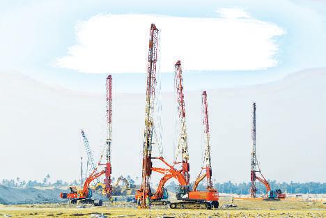


In the Australian Standard (AS1170.4, 2007), the additional capacity to withstand seismic actions is resolved into the performance factor (Sp) which takes into account contributions from the over-strength of materials and the structural system as a whole in sustaining earthquake generated lateral forces whereas the ductility ratio (μ) takes into account contributions from the ability of the structure to deform in a ductile manner (AEES, 2009). The value of Sp is taken by default as 0.77 and the value of μ is taken as 2.0 by defaultforlimitedductilereinforcedconcrete,structuralsteel or composite structures which employ concrete and steel as construction materials. The composite factor of 2.6 (being μ/ Sp or 2/0.77) that is used as default design value in Australia can be compared to a slightly lower, more conservative, q value of 2.0 recommended in the National Building Code of Canada (NBCC) since its 2005 edition. Given that the default q value stipulated in the NA for Singapore is 1.5 which is consistent with recommendations by EC8, members of the study group have agreed to this figure for use in Malaysia, pending further studies in the future to justify a higher value. A local study (Chiang et al., 2012) revealed that the mean strength to characteristic strength ratio of thousands of concrete cube tests up to grade C40 in Malaysia was 1.2, which justified the recommendation for over-strength factor. The inherent ductility of concrete structures is conservatively assumed as 1.25 to arrive at a q value of 1.5 in totality. The recommended and default values of q that is stipulated in regulatory documents in countries of low to moderate seismicity for limited ductile structures are listed in Table 3.
EC8 recommends an upper threshold value of ag = 0.78 m/ s2 for low seismicity, which is based on a RP of 475 years. As the hazard level of Malaysia is benchmarked on a 2,475 year RP, such threshold value has been scaled up by the actual demand ratio of RP 2,475 years to 475 years which is equal to 2.4 (Lam et al., 2015). Hence, a value of ag = 1.87 m/s2 for a RP of 2,475 years shall be adopted as the upper threshold value for low seismicity, while the whole of Malaysia can be classified as low seismicity.
EC8 recommends an upper threshold value of ag = 0.39 m/s2 for very low seismicity, which is based on a RP of 475 years. Likewise, a value of ag = 0.94 m/s2 for a RP of 2,475 years can be adopted as the upper threshold value for very low seismicity. Hence, no part of Malaysia is classified as very low seismicity. In other words, no parts of Malaysia should be put into the “no requirement for seismic design” category. In an intraplate region like Malaysia, areas that have never experienced earthquake tremors should not be automatically declared free of local earthquakes in the future. That is an unsafe assumption to make.
i. Lifeline facilities, including hospitals and infrastructure in support of emergency services, are to be designed to fulfil “no collapse” (life safe) performance criterion for a return period of 2,475 years. Lower design seismic actions are recommended for buildings of other importance classes.
ii. Response spectrum to be used for design purposes, is scaled in accordance with the considered notional design peak ground acceleration values on rock sites which vary between 0.06g and 0.10g for Peninsular Malaysia and Sarawak and between 0.10g and 0.18g for Sabah for various importance classes and return periods. Exact values as presented in the tables depend on the importance classification of the building.
iii. The allowable inter-storey drift limit to satisfy no collapse criterion is recommended to be 1.5%.
iv. Design actions at the member level, such as bending moments and shear forces, are to be scaled down by 1/q where q is the behaviour factor. Members of the study group have agreed to the default value of 1.5 consistent with practice in Singapore but larger values could be adopted. The default values adopted in Canada and Australia are higher.
ACKNOWLEDGEMENTS
We acknowledge the continuous support from IEM in the facilitation of the many workshops and meetings over the years, culminating in the drafting of the National Annex. We also acknowledge the intellectual input by E.P. Lim, Ahmed Zuhal Zaeem and other active participants from EC8 TC as well as Edmund Booth, who provided the first author with very useful advice in relation to Eurocode 8.
Notations
Sp performance factor
ag notional design peak ground acceleration on rock
dr design interstorey drift q behaviour factor
qd displacement behaviour factor
γI importance factor
μ ductility ratio
ν reduction factor for interstorey drift limit associated with the damage limitation requirement.
[1] AS 1170.4 (2007) Structural Design Actions – Part 4 Earthquake Actions. Standards Australia.
[2] AEES (2009) AS 1170.4 Commentary: Structural Design Actions – Part 4 Earthquake Actions. Victoria: Australian Earthquake Engineering Society.
[3] BC3 (2013) Guidebook for Design of Buildings in Singapore to Design Requirements in SSEN-1998-1. Singapore: Building and Construction Authority.
[4] Booth, E. (2014) Personal communications in December 2014.
[5] BSI (2008) NA to BS EN1998-1: 2004 UK National Annex to Eurocode 8: Design of Structures for Earthquake Resistance. Part 1: General Rules, Seismic Actions and Rules for Buildings, British Standards Institution (BSI), London, U.K.
[6] CEN (2004) EN 1998 1. 2004. Eurocode 8: Design of Structures for Earthquake Resistance – Part 1: General Rules, Seismic Actions and Rules for Buildings. European Committee for Standardisation, Brussells.
[7] Chiang, J.C.L.,Tu,Y.E.,Tan, C.S. (2012), Gauging the reliability of structural design for buildings and infrastructures from Malaysian Engineers’ viewpoint, The Twelfth East Asia-Pacific Conference on Structural Engineering and Construction (EASEC-12), Hong Kong Special Administrative Region, China, 24-26 January 2011.
[8] Fardis, M.N. (2009) Seismic Design Assessment and Retrofitting of Concrete Buildings based on EN – Eurocode 8, Springer.
[9] Lam, N.T.K., Lumantarna, E., Tsang, H.H., Wilson, J.L. (2015). Results of probabilistic seismic hazard analysis assuming uniform distribution of seismicity. Proceedings of the 10th Pacific Conference on Earthquake Engineering, 6 - 8 November 2015, Sydney, Australia.
[10] Mitchell, D., Paultre, P., Tinawi, R., Saatcioglu, M., Tremblay, R., Elwood, K., Adams, J., and DeVall, R. (2010) “Evolution of seismic design provisions in the National building code of Canada” Canadian Journal of Civil Engineering. 37: 1157-1170.
[11] NA to SS EN 1998 1. 2013. Singapore National Annex to Eurocode 8: Design of Structures for Earthquake Resistance –Part 1: General Rules, Seismic Actions and Rules for Buildings. Singapore: SPRING Singapore.
[12] NRCC (2005) National Building Code of Canada, Associate Committee on the National Building Code, National Research Council of Canada, Ottawa, ON.
[13] SEAOC (1995) Vision 2000: Performance-Based Seismic Engineering of Buildings, Structural Engineers Association of California Sacramento, California, U.S.
[14] Tsang, H.H. (2011) “Should we design buildings for lowerprobability earthquake motion?” Natural Hazards 58: 853-857.
[15] Tsang, H.H. (2014) “Seismic Performance Requirements and Collapse Risk of Structures” Proceedings of the Annual Seminar entitled “Advances in Seismic Engineering” HKIE/IStructE Joint Structural Division. 58-75.
Title: Half Day Seminar on Selection of Steel Materials And Compliance With Structural Eurocodes
20 January 2016
Organised by : Civil and Structural Engineering Technical Division
Time : 8.30 a.m. – 1.00 p.m. CPD/PDP : 3.5
Kindly note that the scheduled events below are subject to change. Please visit the IEM website at www.myiem. org.my for more information on the upcoming events.
(Photos
This paper introduces a quasi-static method of analysis which circumvents issues generated by uncertainties in the natural period properties of real building structures. Decisions leading to the proposal are explained and terminologies clariied.
KEYWORDS
National Annex to Eurocode 8, Seismic Design Actions, quasistatic method of analysis.
A quasi-static method of analysis, which is essentially the “Code Lateral Force Method”, offers an alternative to the conventional procedure to circumvent issues generated by uncertainties in the natural period properties of real buildings. Eurocode 8 (EC8) (CEN, 2004) makes reference to the lateral force method of analysis and the dynamic modal response spectrum method of analysis. The lateral force method is essentially a static analysis method based on a pre-determined lateral force which is representative of the design seismic actions. The dynamic analysis method is particularly encouraged in EC8 and is regarded as the “Reference Method” in view of the availability of commercial packages possessing dynamic analysis capability in most structural design offices in Europe and other advanced economies in other parts of the globe.
Static analysis is still permitted by EC8 but stringent prerequisites apply as summarised in the following:
i. The fundamental natural period of vibration (T1) of the building does not exceed 4Tc or 2s whichever is the less, where Tc (the corner period of the response spectrum) is 0.3s on rock or stiff soil sites.
ii. Criteria for verticality of the building in elevation, or vertical regularity must be satisfied.
The first criterion is controlled by the 4Tc (or 1.2s) threshold on rock or stiff soil sites. Most buildings of up to 50m in height (16 storeys) comply with this requirement. In view of most structures having some form of irregularity to fulfil architectural and functional requirements, the second criterion can be described as very stringent and this may preclude the majority of building structures from design by static analysis only.
Although most design offices possess software having dynamic analysis capability, most undergraduate degree programs in civil/structural engineering do not have substantial coverage on this topic in the core curriculum. The average engineering graduate may not have adequate knowledge and training to review dynamic analysis results generated by the computer and have them incorporated in the calculation of design actions (namely bending moment and shear force) at the member level. Enforcing dynamic
analysis on structures can be counter-productive when the underlying principles are not well understood. A static analysis, despite its short comings of not allowing for higher mode effects in a dynamic response, has the merit of being easy to comprehend by the average structural engineering designer.
The vertical regularity prerequisite in EC8 should be relaxed in view of recent findings from the literature that buildings with T1 < 1.5s (which is fulfilled by most buildings with height of up to 50m, or 16 storeys) are unlikely to experience any significant higher mode effects in their dynamic response to earthquake ground shaking. Analyses that have been reported to support this proposition include buildings possessing mass and stiffness irregularity in the elevation of the building (Su et al., 2011; Fardipour et al., 2011; Zhu et al., 2007). In Australia (AS 1170.4, 2007; AEES, 2009), dynamic analysis is only required for buildings exceeding 50m (16 storeys) which are found on rock or stiff soil. In Singapore (NA to SS EC8, 2013; BC3, 2013), only one of the two prerequisites listed in the above need to be fulfilled.
In view of findings reported from the literature and prerequisites imposed by codes of practices in other areas of low to moderate seismicity, it is recommended that buildings of up to 25m in height be subjected to lateral force analysis method, irrespective of its regularity conditions in elevation.
The lateral force method of analysis, as stipulated in EC8, entails the determination of the natural period of vibration, T1, using equation (1a), the determination of the design base shear, Fb, using equation (1b) and the determination of lateral forces, Fi, applied to individual floor levels in the building using Eq. (1c).
T1 = 0.05H 0.75 where H is the building height. (1a)
Fb = Sd (T1) / λm (1b) where Sd (T1) is the design response spectral acceleration at period T1, and λm is the effective mass of the building and λ can be taken as 85% of the total mass (Clause 4.3.3.2.2(1)P).
Fi = Fb (1c)
δimi δimi Σ i
where δi is the deflection at floor level i of the building when subject to the lateral force and mi is the floor mass.
While the prescriptive based lateral force method, as summarised above, appears straight forward, the estimated lateral actions on the building may be significantly higher than
the actual values, mainly because of uncertainties in the natural period properties of the building concerned. The conservatism stems from inconsistencies in the natural period value calculated by equation (1a) and that reported by the computer analysis of the structural frame model of the building. This problem can be circumvented by introducing the capacity spectrum method (in a linear elastic analysis setting) which makes use of the calculated static deflection of the building to infer on an improved estimate of the fundamental natural period of vibration of the building. The revised lateral forces and the corresponding deflection can be significantly lower than that estimated by equations (1a) to (1c). Only static analyses are involved and these are easy for the average structural engineer to understand.
The lateral force method and the capacity spectrum method (which is referred herein collectively as the quasi-static method of analysis) are illustrated in the following eight-storey building under Malaysian seismic actions. The reinforced concrete hospital building (Figure 1), corresponding to Class IV importance level and situated on a flexible soil site (site period TS = 0.5 s), measures 31.2m × 93.8m on plan and stands at a height of 25.6m above ground. The lateral force resisting system is contributed by wall-frame interaction. The typical storey height is 3.2m, typical span is 7.8m with 600mm × 600mm secondary beams separating the 150mmthick slabs into one-way action. The main beams are sized at 800mm × 600mm. The wall thickness is 250mm, dimension of major columns is 850mm × 800mm, except for the 450mm × 450mm corner columns at the two wings. For gravity load, a superimposed dead load of 5.2 kPa is estimated for partitions, finishes and ceilings, and an average live load of 5 kPa is adopted (Looi et al., 2015).
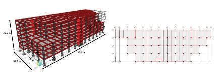
The Lateral Force method of analysis, as stipulated in EC8, entails the determination of the natural period of vibration, T1, using equation (1a), the determination of the design base shear, Fb, using equation (1b) and the determination of lateral forces, F, applied to individual floor levels in the building using equation (1c).
Step One: Identifying building height (H), calculating codified natural period of vibration (T1) using equation (1a) and calculating response spectral acceleration (Figure 2).
H = 25.6 m
T1 = 0.05 (25.6)0.75 = 0.57 s
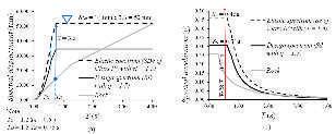
Figure 2: Elastic and design response spectrum (a) displacement and (b) acceleration on a Flexible Soil Site (TS = 0.5 s) for Class IV building
Sd = Se γI / q = 0.31g × 1.5 / 1.5 = 0.31g, where γI is the importance factor (1.5 for Class IV) and q is the behaviour factor (1.5 proposed in the NA).
We are a supplier of high quality geosynthetic products used for soft soil stabilization, slope reinforcement, coastal erosion protection, river bank protection, landfills, drainage, road and railway construction.
Our Products: NEXTILE NON-WOVENS
NEXFORCE HIGH-STRENGTH WOVENS
NEXGRID GEOGRIDS
We also provide design, specification, bill of quantities, cost estimate and drawings free-of-charge.


Step Two: Finding base shear FB using equation (1b)
Mass, m = 76,862 ton
Fb = 0.31g (0.85)(76,862) = 198,683 kN
Step Three: Distributing the base shear into equivalent static force at each storey using equation (1c) by replacing lateral displacement (δ) with heights (z) of the masses, assuming fundamental mode shape is approximated by δ increasing with z (see Table 1). The static load should be applied to two orthogonal directions on plan. The lateral force method as required by EC8 is completed at this point. Analysis may continue with the quasi-static method for obtaining improved estimates.
Step Four: Structural analysis to obtain the force at each floor (Fi), displacement at each floor (δi) (see Table 1) and effective displacement value (δeff) are calculated using equation (2).
Table 3: Force and displacement at individual loors in lateral Y direction.
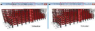
Step Seven: Calculate seismic demand and superpose demand diagram on the acceleration-displacement diagram for the building (Figure. 4).
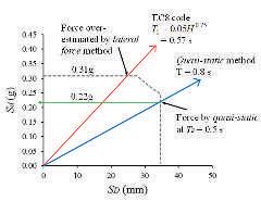
4: Capacity spectrum method
8
7
4
3
2
(2)
Step Five: Calculating effective mass (meff) and improved estimate of response spectral acceleration (Sd) from equation (1b)
(3)
Step Eight: Repeat Step Three with the improved accuracy of demand.
Fb = 0.22g (0.8)(76,862) = 132,707 kN
Table 4: Improved force estimation and displacement at individual loors in lateral Y direction.
Step Six: Calculating effective stiffness (keff), natural period of vibration (Teff) and drawing acceleration-displacement diagram for the building structure.
Compared to the results obtained from ETABS (CSI, 2003) simulation, the first mode shape period is 0.81 s in the X direction and second mode shape period is 0.79 s in the Y direction (Figure 3).
Table 5. Interstorey drift ratio check in the Y-direction
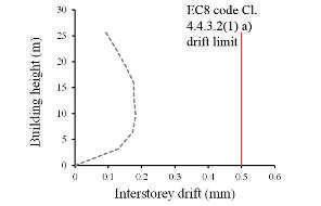
Subsequent rigorous design based on acceptance criteria for ultimate strength and damage limitation (service ability) drift check of structural members should be carried out accordingly. An example of damage limitation check in the Y-direction for the hospital (Class IV building) is shown in Table 5 and Fig. 5. The displacement behaviour factor (qd) is assumed equal to q as 1.5, the reduction factor (ν) is taken as 0.5 (Lam et al., 2016) and the limitation for interstorey drift ratio for “buildings having non-structural elements of brittle materials attached to the structure" is assumed as 0.5%.
1. Lateral Force method of analysis is allowed for buildings of up to 50m (16 storeys) in height and is recommended for buildings of up to 25m (8 storeys), irrespective of the regularity conditions in elevation.
2. Estimates by the Lateral Force method may be overly conservative because of uncertainties in the natural period properties of the building concerned.
3. The predicted lateral forces and the corresponding deflections may be revised to lower values by applying the capacity spectrum method (in a linear elastic analysis setting) which makes use of the calculated static deflection of the building to infer an improved estimate of the fundamental natural period of vibration of the building.
4. The Lateral Force method and the Capacity Spectrum method are collectively described as the quasi-static method of analysis, which is illustrated by an example eight-storey building.
5. It is shown by example that the lateral force and deflection demand have been overstated by the Lateral Force method by a factor of 1.4 approximately.
We acknowledge the continuous support from IEM in the facilitation of the many workshops and meetings over the years, culminating in the drafting of the National Annex. We also acknowledge the intellectual input by E.P. Lim, Ahmed Zuhal Zaeem and other active participants from EC8 TC.
Notations
Fb design base shear
Fi lateral force at floor level i
H height of building
SD(T) design displacement response spectrum
SDe(T) elastic displacement response spectrum
Sd(T) design response spectral acceleration
Sd(T1) design response spectral acceleration at period T1
Se(T) elastic horizontal ground acceleration response
T1 fundamental natural period of vibration
TC first corner period
TD second corner period

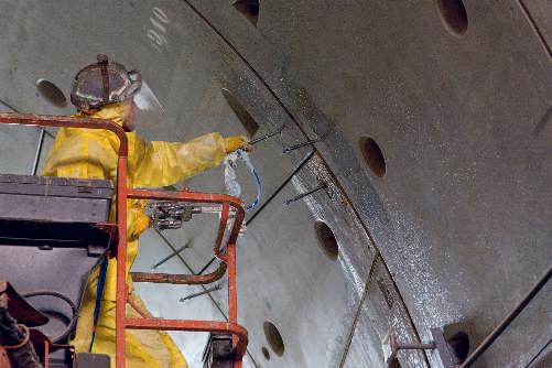
TS initial low-amplitude site natural period (note: this symbol is different from EC8 where Ts is referred as the duration of the stationary part of the seismic motion)
Teff effective natural period of vibration
de displacement of the same point of the structural system, as determined by a linear analysis based on the design response spectrum
dr design interstorey drift
ds displacement of a point of the structural system induced by the design seismic action
keff effective stiffness
meff effective mass
m floor mass at floor level i
q behaviour factor
zi floor height at floor level i
i deflection at floor level i
I importance factor
λ mass correction factor
ν reduction factor for interstorey drift limit associated with the damage limitation requirement.
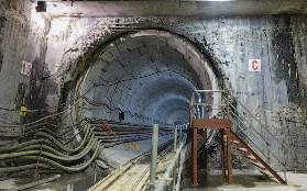
[1] AS 1170.4 (2007) Structural Design Actions – Part 4 Earthquake Actions. Standards Australia.
[2] AEES (2009) AS 1170.4 Commentary: Structural Design Actions – Part 4 Earthquake Actions. Victoria: Australian Earthquake Engineering Society.
[3] BC3 (2013) Guidebook for Design of Buildings in Singapore to Design Requirements in SSEN-1998-1. Singapore: Building and Construction Authority.
[4] CSI (2003). ETABS Integrated Building Design Software Introductory User's Guide. Computers and Structures, Inc. Berkeley, California, USA.
[5] CEN (2004) EN 1998 1. 2004. Eurocode 8: Design of Structures for Earthquake Resistance – Part 1: General Rules, Seismic Actions and Rules for Buildings. European Committee for Standardisation, Brussells.
[6] Fardipour, M., Lumantarna, E., Lam, N., Wilson, J., Gad, E. (2011). Drift Demand Predictions in Low to Moderate Seismicity Regions, Australian Journal of Structural Engineering 11(3), 195-206.
[7] Lam, N.T.K. (2011), “Use of Spreadsheets for Analyses in Structural Engineering”, Applications of Spreadsheets in Education: The Amazing Power of a Simple Tool, (Ed. Sugen, S. & Kwan, M.), Bentham Science Publisher: Chapter 2, 16–40.
[8] Lam, N.T.K., Tsang, H.H., Wilson, J.L., Looi, D.T.W., Hee, M.C. (2016). Performance criteria and design parameters. JURUTERA (the monthly bulletin of the Institution of Engineers, Malaysia). January Issue.
[9] Looi, D.T.W., Lam, N.T.K., Tsang, H.H., Hee, M.C. (2015). Seismic analysis in the low to moderate seismicity region of Malaysia based on the draft handbook. Proceedings of the 10th Pacific Conference on Earthquake Engineering, 6 - 8 November 2015, Sydney, Australia.
[10] NAto SS EN 1998 1. 2013. Singapore NationalAnnex to Eurocode 8: Design of Structures for Earthquake Resistance – Part 1: General Rules, Seismic Actions and Rules for Buildings. Singapore: SPRING Singapore.
[11] Su, R.K.L, Tsang, H.H. and Lam, N.T.K. (2011) Seismic Design of Buildings in Hong Kong, Department of Civil Engineering, The University of Hong Kong.
[12] Zhu, Y., Su, R.K.L. and Zhou, F.L. (2007). Cursory Seismic Drift Assessment for Buildings in Moderate Seismicity Regions, Earthquake Engineering and Engineering Vibration 6(1), 85-97.
Title: Technical Visit to Boustead Shipyard and Royal Malaysian Navy Base, Lumut 22 - 23 January 2016
Organised by : Project Management Technical Division Time : 7.00 a.m. – 5.00 p.m. CPD/PDP : 5.5
Kindly note that the scheduled events below are subject to change. Please visit the IEM website at www.myiem.org.my for more information on the upcoming events.

In order to understand the implications of earthquake design in Malaysia, a cost study was undertaken by the Working Group 1 of IEM Technical Committee for Earthquake. Since Malaysia would soon adopt Eurocode as the design standard and, with the development of the Malaysian NA to EC8, studying all aspects of earthquake engineering is deemed necessary. Therefore with the introduction of the design spectrum for Malaysia, the cost study is a stepping stone for engineers in understanding the implication of earthquake design guidelines in Malaysia.
Typical office buildings ranging from 1-storey, 5-stories, 10-stories, 20-stories and 30-stories degenerated into 2 Dimensional buildings for ease and simplicity in analysis (Fig. 1a to Fig. 1e) and typical link houses ranging from 1-storey and 2-stories were used in the study (Fig. 1f to Fig. 1g). Given that the majority of structures built in Malaysia are reinforced concrete, the study limits all the buildings to reinforced concrete. All the buildings were analysed and designed using structural design programme, Midas Gen 2015 and for quantities taking off, Midas DShop was utilised. The office buildingsarebuiltoutofreinforcedconcreteofgradeC30/37 and the link houses are built out of reinforced concrete of grade C20/25. For reinforcing steel, yield strength of Class B rebar for longitudinal reinforcement and stirrups is utilised. Two models were developed for each type of building. One was subjected to static loading and one was subjected to both static and earthquake loading. The two replicas were analysed and designed on the assumption that they were uncracked. They were subjected to pushover analysis in order to determine whether the sections weare cracked or not. If the buildings fall under cracked sections, the property of the building is assumed cracked, thus reducing the stiffness of all members by 50% as per BS-EN1998-1:2004
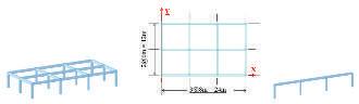

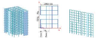
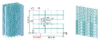
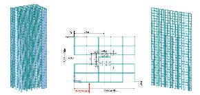

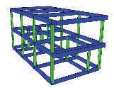
Each of the office buildings was designed to a uniform building density of 3.4 kN/m3. For link houses, superimposed dead load of 2.5 kPa and a live load of 1.5 kPa was adopted. Wind loads were applied as per BS-EN1991-1-4 2005, with a basic wind speed of 20 m/s inside city. Notional imperfection load was applied, taking maximum inclination of 1/200 for 1 and 2-stories buildings and 1/400 for 5, 10, 20 and 30-stories buildings. This amounted to 0.5% of the ultimate dead and live load for the 1 and 2-stories buildings and 0.25% of the ultimate dead and live load for the 5, 10, 20 and 30-stories buildings. Earthquake loading was also been applied as per the Malaysian hybrid design spectrum of the Malaysian National Annex EC8. All buildings were assumed to be located on stiff soil sites consistent with most Malaysian soil condition. As for computations of the natural period of vibration, which was a function of stiffness and mass of the building, the design seismic mass was formulated using equation 1. m= ∑Gk,i+ ∑ΨE,j .Qk j (1)
where Gk and Qk the characteristic dead and imposed mass respectively. Ψ is taken as 0.3 taking into account the likelihood that imposed load is not present over the entire structure during the earthquake.
Under the clause 4.3.1 of EC8, the stiffness of the cracked structural elements can be taken as 50% of its original uncracked stiffness. In order to determine whether the structure is cracked or un-cracked, a pushover analysis is performed. The capacity curve (Fig. 2a) for 1-storey link house gives the maximum displacement in metres of the building against lateral load in kilo Newton. The building experiences its first crack at 360kN (α1). Hence the pushover capacity curve was superimposed over the acceleration displacement response spectrum of Peninsular Malaysia to determine the performance point (Fig. 2b). Since the performance point is above the α1 (which is the first crack), this indicates that the structure has cracked, hence concluding that the building has cracked and the analysis is carried out under cracked section properties. This reduction in stiffness increased the first mode period of the 1-storey link house from 0.25s to 0.35s and the 2-storey building from 0.48s to 0.67s.
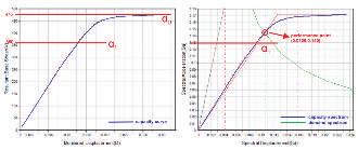
Cost Estimation is calculated under static load conditions (dead load, imposed load, wind load and notional
imperfection load) and under combined static and earthquake load. One standard deviation is calculated with the two samples of 1-storey and 2-storey buildings and applied to the costing to cover uncertainties.
The percentage differences in costs is estimated as shown in Fig. 3a for office buildings and Fig. 3b for link houses. The highest increase in cost is predicted for Sabah (8.1% for a 10-storey office building and 4.8% for 2-storey link house).
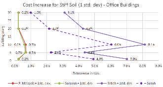
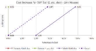
The highest cost estimation (with 1 standard deviation) for Peninsular Malaysia/Sarawak for office buildings is 0.7% and 0.6% respectively for 10-storey office building. The highest increase in cost for Sabah is 8.1% for 10-storey. For Peninsular Malaysia and Sarawak, link houses have no change in the structural cost. For Sabah the cost increases for single and double storey houses are 2.0% and 4.8% respectively.
TheauthorswouldliketothanktheIEMEarthquakeTechnical Committee for the technical and financial support given to conduct the research. Valuable intellectual inputs by various participants from EC8 TC are also gratefully acknowledged.
[1] CEN (2004) EN 1998 1. 2004. Eurocode 8: Design of Structures for Earthquake Resistance – Part 1: General Rules, Seismic Actions and Rules for Buildings. European Committee for Standardisation, Brussells.
[2] CEN (2005) EN 1991 1. 2005. Eurocode 1: Actions on structures. General actions – Wind actions-Part 4. European Committee for Standardisation, Brussells.
[3] CEN (2004) EN 1992 1. 2004. Eurocode 2: Design of concrete structures - Part 1-1: General rules and rules for buildings. European Committee for Standardisation, Brussells.
[4] Hee, M. C., Tsang, H. H., and Lam, N. T. K., Looi, D.T.W., (2015) “Drafting the Malaysia National Annex to Eurocode 8: Recommended Seismic Loadings and Cost Implication” IStrcutE Internationl Conference.
[5] Hee, M. C., Tsang, H. H., and Lam, N. T. K., Looi, D.T.W., (2015) “Draft NationalAnnex to Eurocode 8 for Malaysia and cost implication for residential buildings with thin size elements” Proceedings of the Ninth Paciic Conference on Earthquake Engineering Building an Earthquake-Resilient Paciic 6-8 November 2015, Sydney, Australia.
[6] Lam, N.T.K. (2015). Earthquake Environment Surrounding Different parts of Malaysia. Lecture notes on How to utilise our proposed EC8 Malaysia NA for our practising consulting engineers, IEM professional short course, 29 – 30 September 2015, Armada Hotel Petaling Jaya, Malaysia.
[7] Looi, D.T.W., Hee, M.C., Tsang, H.H., Lam, N.T.K. (2014). Updated Design Spectrum for Peninsular Malaysia.Proceedings of presentation at 2-day workshop on recommended earthquake loading model in the propose NAto EC8 for Sabah, Sarawak & updated model for Peninsular Malaysia, 16 – 17 July 2014,Armada Hotel Petaling Jaya, Malaysia.
[8] MIDAS (2015). MidasGen Seismic Design for Reinforced Concrete Building Tutorial. MIDAS Information Technology Co., Ltd, Korea.
[9] MIDAS (2014). Midas DShopBasic Tutorial Reinforced Concrete Structure. MIDAS Information Technology Co., Ltd, Korea.
[10] Tsang, H.H., Lam, N.T.K., Looi, D.T.W., Wilson, J.L., Hee, M.C. (2016). “Site Classiication and Response Spectrum Model for Soil Sites” JURUTERA (the monthly bulletin of the Institution of Engineers, Malaysia). January Issue.

Ir. Adjunct Prof. M C Hee is a practicing Structural Consulting Engineer and Principal of M C Hee & Associates. His expertise is in the design and construction of high-rise buildings particularly in value engineering and alternative design. His philosophy is "design for simplicity and buildability'' with a "total concept approach". He has over 40 years of experience in this ield. He was a Vice President of IEM and the chairman of IEM C&S WG1 for Malaysia EC8 earthquake code annex drafting. He is an Adjunct Professor in Civil Engineering at the Department of Civil Engineering, University Malaya.

Prof. Nelson Lam, Reader in Civil Engineering at The University of Melbourne, is an internationally recognized expert in earthquake engineering and structural dynamics. In the past 20 years, he has been researching and consulting widely in this ield. He served as member of the sub-committee for developing the new standard for Earthquake Actions in Australia and wasco-editor and co-author of the standard’s commentary. His early career was with Scott Wilson International as structural engineer in their Hong Kong Ofice through out the 1980’s and attained chartered engineer status in 1986.


Ir. Lim Ek Peng is a practicing engineer with Perunding Hashim & NEH Sdn. Bhd. He has extensive experience in civil and structural engineering design and construction. He was a member of technical committees of (IEM-SWO) for Standards in Design of Concrete Structures.

Engr. Looi Ting Wee Grad. IEM, is a PhD candidate in University of Hong Kong under supervision of Assc. Prof. Ray Su, researching on earthquake and structural engineering. Prior to postgraduate study, he worked as a structural application engineer serving both high-rise building and plant industry.Around 5 years of experience, he has done numerous demonstration, training and professional consultancy to various companies in South East Asia, Australia, New Zealand, India and the Middle East. He is actively involved in IEM C&S WGl for Malaysia EC8 earthquake code annex drafting

Dr Tsang Hing Ho, is a Senior Lecturer Faculty of Science, Engineering and Technology School of Engineering, Swinburne University of Technology, Australia. He has taught at The University of Hong Kong, and is currently a visiting professor at Karlsruhe Institute of Technology, Germany. He has published over 80 technical publications. He is currently serving as an Advisor for the Hong Kong Housing Authority on seismic design of building structures.

Engr. Ahmed Zuhal Zaeem Grad. IEM, is pursuing his post graduate studies on earthquake and structural engineering in Universiti Malaya. Concurrently working for M C Hee & Associates gaining experience in structural engineering. He is actively involved in IEM C&S WGl for Malaysia EC8 earthquake code annex drafting.
Prof. John Wilson, is Executive Dean of Engineering and Industrial Sciences at Swinburne University of Technology in Melbourne. He was the Victorian Division Chairman of Engineers Australia in 2002, and is a member of the steering committee for the Victorian Infrastructure Report Card 2005 and 2010, Chairman of BD6/11, the committee responsible for the earthquake loading standard for Australia, a member of ACI307 Committee and Chairman of Judges for the 2011 and 2013 Victorian Engineering Excellence Awards.


Engr. Izni Zahidi is currently attached with CH2M as a water engineer and inishing a PhD in water resources engineering at Universiti Putra Malaysia. She has lived in ive different countries as part of her studies and travelled to many more.

Fancy discovering a fossil or two? Just bring your brushes to Mons Klint on the island of Mon in South Zealand, Denmark. I may not be Indiana Jones, but I simply grabbed the opportunity to see the cliffs when my Danish host kindly offered to drive us there.
It took us nearly three hours to get there from Copenhagen because we stopped a few times along the way to see the mills, wheat fields and little villages. Blame the tourist in me, but these were too picturesque to just drive through and be content with looking out the car window.
As we got close to the cliffs, a peaceful forest opened up to reveal a futuristic building – Geocenter Mons Klint. This geological museum first opened in 2007. Most of the structure was built underground to reduce the effect on the environment as it would have looked out of place amidst the lush green forest. Visiting the museum was like taking a crash course in the cliffs formation and fossils you could unearth such as octopus, sea urchin or mussel.
The 7km-long Mons Klint itself is a spectacular sight of bright white chalk cliffs, a stunning contrast against the blue and green shades of the Baltic Sea. Some 70 million years ago, Denmark was under the sea, lands were raised and mountains were formed. The chalky prehistoric ocean floor was uncovered after the ice from the last Ice Age (dated 12,000 years ago) melted. The chalk came from settled micro-organisms which were compressed in the
ancient seabed. That explains why the country is generally flat; at 128m, Mons Klint is already the highest point in the country.
This highest point of the cliffs is also called “The Queen’s Chair” or known locally as Dronningestolen (photo). According to a romantic legend, whenever the Cliff King sailed off on an expedition, the Queen would sit there and watch out over the ocean.
During the Ice Age, the limestone was pushed to the surface by glaciers covering northern Europe. It did not stop there. The cliffs are still changing and 20-40cm have disappeared into the sea.
Just a few years back, in 2007, a grand cliff formation called Store Taler, collapsed by 100m due to erosion and moved horizontally into the Baltic Sea by another 300m. Although you can still see the fallen cliff as a white peninsula, it will, in due course, be swallowed by the sea. I wouldn’t be surprised if the cliffs I saw a couple of years ago looked slightly different today.
There are several trails available which providedifferentviews.Wetrekkedthe267m-long wooden boardwalk along the edge of the cliffs; this had an amazing view of the Baltic Sea and the rich bird life.
We were lucky that the day was clear and we could even see neighbouring Sweden and Germany. We also saw the world’s fastest animal (no, not the cheetah!), the peregrine falcon. These majestic birds had almost become extinct, but the natural caves on the steep chalky cliffs provided them with ideal nests for breeding. So after a spell of 30 years, they can now be seen again.
Apart from the birds (and butterflies too), Mons Klint is famous for orchids which flourish here due to the high content of limestone in the soil. Go on a hike in the virgin forest and you can see a number of rare orchids, including 20 different species of wild orchids. As tempting as it may be, you are not allowed to pick the flowers as they are all protected.
There is a huge rock in the middle of the trail and one cannot help but wonder where it came from. Legend had it that a Swedish sorceress, outraged that Christianity was spreading in the north, used her garter to hurl agranite stone at the church of Magleby, 5km from the cliffs. However, the stone only hit the church tower, ricocheted and landed in the forest.
I cannot say if the legends are real, but I do know Mons Klint is definitely magical.

To All Members,
Tarikh: 7 December 2015
BerikutadalahsenaraicalonyanglayakuntukmendudukiTemuduga Profesional bagi tahun 2016.
Mengikut Undang-Undang Kecil IEM, Seksyen 3.8, nama-nama seperi tersenarai berikut diterbitkan sebagai calon-calon yang layak untuk menjadi Ahli Insitusi, dengan syarat bahawa mereka lulus Temuduga Profesional tahun 2016.
Sekiranya terdapat Ahli Korporat yang mempunyai bantahan terhadap mana-mana calon yang didapai idak sesuai untuk menduduki Temuduga Profesional, surat bantahan boleh dikemukakan kepada Seiausaha Kehormat, IEM. Surat bantahan hendaklahdikemukakansebulandaritarikhpenerbitandikeluarkan.
Ir. Yam Teong Sian Seiausaha Kehormat, IEM,
PERMOHONAN BARU NamaKelayakan
KEJURUTERAAN AWAM
KHADIJAH BINTI ABDUL RAZAKBE HONS (UTM) (CIVIL, 2007)
LIM BEE KOON, CORINNEBE (HONS) (UTM) (CIVIL, 2003)
MOHD ALFIAN BIN ABU BAKAR BE HONS (UiTM) (CIVIL, 2007)
MOHD HAZULLAH BIN ZULKIFLIBE HONS (UTM) (CIVIL, 2008)
SHAMSUL BIN ABD MANAFBE HONS (UiTM) (CIVIL, 2006)
KEJURUTERAAN ELEKTRIKAL
LIM JOO SIANGBE HONS (UNITEN) (ELECTRICAL POWER, 2008)
MOHAMAD SUHAIMI BIN ANUARBSc (NEW MEXICO) (ELECTRICAL, 1996)
KEJURUTERAAN AERONAUTIKAL
AZIIZUR RAHMAN BIN ABDULAZIZ BE HONS (UTM) (MECHANICAL-AERONAUTICS, 2009)
KEJURUTERAAN KAWALAN & INSTRUMENTASI
FRANKLIN ANAK UCAR BE HONS (UKM) (ELECTRICAL, ELECTRONIC & SYSTEM, 1995) ME (UPM) (ENGINEERING MANAGEMENT, 2006)
KEJURUTERAAN MARIN
MOHD FAZLI BIN MOHD YUSOFBE HONS (UTM) (MECHANICAL - MARINE TECHNOLOGY, 2007)
PERPINDAHAN AHLI No. Ahli NamaKelayakan
KEJURUTERAAN AWAM
21588 AHONG ANAK MANCHU BE HONS (UNIMAS) (CIVIL, 2000)
22419 HONG POH TECK BE HONS (RMIT) (CIVIL, 2000)
27654LIM LIANG JIN BE HONS (UTM) (CIVIL, 2006) MSc (TUDelft) (CIVIL, 2012)
43518MA CHAU KHUN BE HONS (UTM) (CIVIL, 2008) PhD (UTM) (CIVIL, 2015)
23916MAGESWARAN PAVADAIBE HONS (MALAYA) (CIVIL, 2000)
17835NG KIM SENGBE HONS (MALAYA) (CIVIL, 1999)
58004ZAINI BIN IBRAHIMBE HONS (UTM) (CIVIL, 2012)
KEJURUTERAAN ELEKTRIKAL
64743 JOHN A/L R.AROKIASAMY BE HONS (UMP) (POWER SYSTEMS, 2011)
60623 LAILATULAKMALABDUL RAUF ME HONS (IMPERIAL COLLEGE LONDON) (ELECTRICAL & ELECTRONIC, 2009)
58642MOHAMAD HELMEE BIN MOHD RORTI BE HONS (UiTM) (ELECTRICAL, 2008)
78422MOHD ALFITRI BIN ZAILANBE HONS (UniMAP) (ELECTRICAL SYSTEMS, 2010)
50756MOHD SUFI BIN ABDUL RAHMANBE HONS (UniMAP) (ELECTRICAL SYSTEMS, 2009)
78415SHEFIAN BIN MD DOMBE HONS (UiTM) (ELECTRICAL, 2005)
KEJURUTERAAN ELEKTRONIK
16394JA'AFAR SIDEK BIN BUDINBE HONS (UTM) (ELECTRICAL, 2012)
33913NOOR ZAIHAH BINTI JAMALBE HONS (USM) (ELECTRONIC, 2005)
79323RUZITA BINTI ABU BAKAR BSc (INDIANA) (ELECTRICAL, 1989) MSc (UPM) (COMPUTER & COMMUNICATION SYSTEMS, 2001)
KEJURUTERAAN MEKANIKAL
23383KHAIRUL SALLEH BIN BASARUDDIN BE HONS (UTM) (MECHANICAL, 2003)
30774MOHD RAZLI ISHAM BIN MD RADZI DZULKHAIRI BE HONS (UNITEN) (MECHANICAL, 2008)
64610TAN KIAN KEONGBE HONS (UKM) (MECHANICAL, 2012)
KEJURUTERAAN ALAM SEKITAR
26793FAZLI BIN RAHIM BE HONS (UTP) (CHEMICAL, 2001) MSc (UKM) (CIVIL & STRUCTURAL, 2012)
KEJURUTERAAN LEBUHRAYA
45804MUHAMAD RAZUHANAFI BIN MAT YAZID BE HONS (UTM) (CIVIL, 1997)
KEJURUTERAAN KAWALAN & INSTRUMENTASI
34371OH LAY SHANBE HONS (UTP)(ELECTRICAL & ELECTRONICS, 2006)
KEJURUTERAAN BAHAN
37286JULIE JULIEWATTY BINTI MOHAMED BE HONS (USM) (MATERIAL, 2001) MSc (USM) (MATERIALS, 2004) PhD (USM) (2008)
KEJURUTERAAN KIMIA
64585AMIZA BINTI SURMIBE HONS (UTP) (CHEMICAL, 2006)
49967NORAZIAH BINTI MUDA@OMARBE HONS (SHEFFIELD) (CHEMICAL PROCESS & FUEL TECHNOLOGY, 1998)
PERMOHONAN BARU MENJADI AHLI KORPORAT
KEJURUTERAAN MEKANIKAL
-NG BOON WAIBE HONS (UKM) (MECHANICAL & MATERIALS, 1993)
ERRATA
SENARAI CALON-CALON YANG LAYAK MENDUDUKI TEMUDUGA PROFESIONAL TAHUN 2015 - SEPTEMBER 2015
PERPINDAHAN AHLI
KEJURUTERAAN ELEKTRONIK
71187MOHAMAD FAZLI BIN MOHAMAD SALLEH BE HONS (UNITEN) (ELECTRICAL & ELECTRONICS, 2009)
SENARAI CALON-CALON YANG LAYAK MENDUDUKI TEMUDUGA PROFESIONAL TAHUN 2015 - NOVEMBER 2015
PERMOHONAN BARU
KEJURUTERAAN AERONAUTIKAL
KHAIRINI MELISSA NG SAU CHENGBE HONS (UPM) (AEROSPACE, 2008)
Title: Talk on Commission of Enquiry Into the Failure of Two Civil Structures in Penang 28 January 2016
Organised by : Standing Committee on Professional Practice
Time : 5.30 p.m. – 7.30 p.m.
CPD/PDP : 2
Title: Talk on “Reduction of Blast-Induced Vibration in Tunnelling Using Barrier Boles and Air-Deck” 16 February 2016
Organised by : Tunneling and Underground Space Engineering Technical Division Time : 5.30 p.m. – 7.30 p.m.
CPD/PDP : 2
Kindly note that the scheduled events below are subject to change. Please visit the IEM website at www.myiem. org.my for more information on the upcoming events.
79014 TAN YEE LIANG, WILLIAM B.E.HONS.(UITM) (ELECTRICAL, 2015)
78416TAY ENG CHONGB.E.HONS.(MONASH) (ELECTRICAL, 2013)
78861TUAN NUR LIYANA BINTI RAJA HASSAN
79088WAN HUZAIRI BIN WAN HUSSIN
79096WAN NURFAZWINA BINTI MAT SOTI
78453WAN ZUHARI BIN WAN ISMAIL
79296YEE HAN MIN, STEPHEN
79074ZAIDI FAIQ BIN MOHD NOH
79093ZULKIFLI BIN MOHD SALLEHAN
B.E.HONS.(UNITEN) (ELECTRICAL POWER, 2012)
B.E.HONS.(UITM) (ELECTRICAL, 2015)
B.E.HONS.(UITM) (ELECTRICAL, 2015)
B.E.HONS.(UTM) (ELECTRICAL, 2001)
B.E.HONS.(UMS) (ELECTRICAL & ELECTRONICS, 2011)
B.E.HONS.(UITM) (ELECTRICAL, 2015)
B.E.HONS.(CURTIN) (ELECTRONIC & COMMUNICATION, 2009)
KEJURUTERAAN ELEKTRONIK
79066ADAM BIN HAIRUL ERWAN B.E.HONS.(IIUM) (COMMUNICATION, 2012)
79160AHMAD MUHAYMIN BIN NISAR AHMAD SALIMI
79148AHMAD SHAZWAN BIN AHMAD SUHAIMI
79111 ARIFFIN NARWES BIN MUHAMMAD JUHIN
B.E.HONS.(MELBOURNE) (ELECTRICAL, 2012)
B.E.HONS.(MMU) (ELECTRONICSROBOTICS & AUTOMATION, 2008)
B.E.HONS.(UTM) (ELECTRICALINSTRUMENTATION & CONTROL, 2011)
79121AZZIZATUL HUDA SABANI B.SC.(UTM)(ELECTRICAL, 1999)
79009 CHANG TZIN, RAYMOND B.SC.(UTM)(ELECTRICAL, 2002)
79065CHE NORZAKIMAN BIN CHE AHMAD
B.E.HONS.(UITM) (ELECTRONIC, 2015)
78897CHEW HOO BENGB.E.HONS.(UTAR) (ELECTRONIC &COMMUNICATION, 2012)
78459DR. LAW KAH HAWM.E.HONS. (NOTTINGHAM) (ELECTRICAL & ELECTRONIC, 2010) P.HD.(NOTTINGHAM) (2015)
79154 FAIDHI AMIN BIN MOHD NAZARNA B.E.HONS.(UITM) (ELECTRONIC, 2015)
79149FELIX CEILOMOND ANAK SAMAM B.E.HONS.(UITM) (ELECTRONIC, 2015)
79064HABIB BIN SHAWALB.E.HONS.(UITM) (ELECTRONIC, 2015)
79142 HAFIDZ BIN AZMI B.E.HONS.(UITM) (ELECTRONIC, 2015)
78450 HERMAN BIN ABU SAINI B.E.HONS.(UTM) (ELECTRICAL-MEDICAL ELECTRONICS, 2001)
79144ISMAIL BIN IBRAHIM EDHAM B.E.HONS.(UITM) (ELECTRONIC, 2015)
79061IZAIDI BIN WAN IBRAHIM B.E.HONS.(UITM) (ELECTRONIC, 2015)
79136IZHAM KHAIRULFATHI BIN BAHRO B.E.HONS.(UITM) (ELECTRONIC, 2015)
79038 LAI SUN YUENN B.E.HONS.(UITM) (ELECTRONIC, 2015)
79058MD BAHARIN SABRI BIN NASIR B.E.HONS.(UITM) (ELECTRONIC, 2015)
79104MIZY SHAMIRUL BIN MASRULHISHAM B.E.HONS.(UITM) (ELECTRONIC, 2015)
79109 MOHAMAD ARIF
AFNAN BIN YAHYA
79105 MOHAMAD AZIZAN
BIN MOHAMAD SAID
79143MOHAMAD FAISAL
BIN AZLAN
B.E.HONS.(UITM) (ELECTRONIC, 2015)
B.E.HONS.(UITM) (ELECTRONIC, 2015)
B.E.HONS.(UITM) (ELECTRONIC, 2015)
Note: Remaining list would be published in the February 2016 issue. For the list of approved “ADMISSION TO THE GRADE OF STUDENT”, please refer to IEM web portal at http://www.myiem.org.my.
SENARAI PENDERMA KEPADA WISMA DANA BANGUNAN IEM
NO. NO. AHLI NAMA
115680AHMAD HUSAIRI BIN ABDULLAH
226586 CHEE JEN YIH
358691CHIA WAN HOONG
454569 CHRISTOPHER ANAK KAYAD 542457 FADHLI BIN ABDULLAH
607524LEE PAK CHOONG
770558 LEE YEN EU
844712 LU TSUI MING
958487NAZURA ZAILAH BT. HAJI ZAINORIN
1015859NG LIN HONG @ PAUL NG 11 65845NUR HAFIZAH ZAINUDIN
1261194ONG KIN BEING 1327992 PATRICK TUIN 1414979RAYMON MANGALARAJ 1545374 SHARULA-RASHID 1624713SHIA SIN SAN 1771592SITI NOORJANNAH BT IBRAHIM 1807366TAI KIM FUI
1944025TAN SOON HAW 2065885WAN NOR ADMATIZA BT. SUHAIMI 2155821ZYKAMILIA BINTI KAMIN

Institusi mengucapkan terima kasih kepada semua yang telah memberikan sumbangan kepada tabung Bangunan Wisma IEM. Ahli-ahli IEM dan pembaca yang ingin memberikan sumbangan boleh berbuat demikian dengan memuat turun borang di laman web IEM http://www.iem.org.my atau menghubungi secretariat di +603-7968 4001/5518 untuk maklumat lanjut. Senarai penyumbang untuk bulan November 2015 adalah seperti jadual di bawah: Pengumuman yang ke-87 The Insituion would like to thank all contributors for donaing generously towards the IEM Building Fund HELP
RM 2,743,456.20 contributed by IEM Members and Committees RM 741,502.00 contributed by Private Organisations
IS