MAJLIS BAGI SESI 2015/2016 (IEM COUNCIL SESSION 2015/2016)
YANG DIPERTUA / PRESIDENT
Y.Bhg. Dato’ Ir. Lim Chow Hock
TIMBALAN YANG DIPERTUA / DEPUTY PRESIDENT
Ir. Tan Yean Chin
NAIB YANG DIPERTUA / VICE PRESIDENTS
Y.Bhg. Dato’ Ir. Dr Andy Seo Kian Haw, Ir. Lee Weng Onn, Ir. Gopal Narian Kuty, Ir. Prof. Dr Ruslan bin Hassan, Ir. Lai Sze Ching, Ir. Lee Boon Chong, Ir. David Lai Kong Phooi
SETIAUSAHA KEHORMAT / HONORARY SECRETARY
Ir. Yam Teong Sian
BENDAHARI KEHORMAT / HONORARY TREASURER
Ir. Prof. Dr Jefrey Chiang Choong Luin
BEKAS YANG DIPERTUA TERAKHIR / IMMEDIATE PAST PRESIDENT Ir. Choo Kok Beng
BEKAS YANG DIPERTUA / PAST PRESIDENTS
Y.Bhg. Academician Tan Sri Dato’ Ir. (Dr) Hj. Ahmad Zaidee bin Laidin, Y.Bhg. Dato’ Ir. Dr Gue See Sew, Y.Bhg. Academician Dato’ Ir. Prof. Dr Chuah Hean Teik, Ir. Vincent Chen Kim Kieong
WAKIL AWAM / CIVIL REPRESENTATIVE
Ir. Prof. Dr Mohd. Zamin bin Jumaat
WAKIL MEKANIKAL / MECHANICAL REPRESENTATIVE
Ir. Dr Kannan M. Munisamy
WAKIL ELEKTRIK / ELECTRICAL REPRESENTATIVE
Y.Bhg. Dato’ Ir. Ali Askar bin Sher Mohamad
WAKIL STRUKTUR / STRUCTURAL REPRESENTATIVE
Ir. Hooi Wing Chuen
WAKIL KIMIA / CHEMICAL REPRESENTATIVE
Ir. Prof. Dr Thomas Choong Chean Yaw
WAKIL LAIN-LAIN DISPLIN / REPRESENTATIVE TO OTHER DISCIPLINES
Ir. S. Kumar a/l Subramaniam
WAKIL MULTIMEDIA DAN ICT / ICT AND MULTIMEDIA REPRESENTATIVE
Engr. Abdul Fatah bin Mohd. Yaim, M.I.E.M.
AHLI MAJLIS / COUNCIL MEMBERS
Ir. Dr Tan Chee Fai, Ir. Kok Hee Poh, Ir. Tiong Ngo Pu, Ir. Yau Chau Fong, Ir. Teh Piaw Ngi, Ir. Kim Kek Seong, Ir. Chong Chin Meow, Ir. Chin Kuan Hwa, Ir. Assoc. Prof. Dr Vigna Kumaran Ramachandaramurthy, Ir. Lee Cheng Pay, Ir. Ong Ching Loon, Ir. Gary Lim Eng Hwa, Y.Bhg. Dato’ Ir. Noor Azmi bin Jaafar, Ir. Aminuddin bin Mohd Baki, Ir. Mohd Radzi bin Salleh, Ir. Ong Sang Woh, Ir. Mohd Khir bin Muhammad, Ir. Assoc. Prof. Dr Norlida Bini Buniyamin, Y. Bhg. Dato’ Ir. Hanapi bin Mohamad Noor, Ir. Dr Ahmad Anuar bin Othman, Ir. Ishak bin Abdul Rahman, Ir. PE Chong, Ir. Ng Yong Kong, Ir. Tejinder Singh, Ir. Sreedaran a/l Raman, Ir. Roger Wong Chin Weng
AHLI MAJLIS JEMPUTAN / INVITED COUNCIL MEMBERS
Y. Bhg. Datuk Ir. Rosaline Ganendra, Y. Bhg. Dato’ Ir. Abdul Rashid bin Maidin
PENGERUSI CAWANGAN / BRANCH CHAIRMAN
1. Pulau Pinang: Ir. Dr Mui Kai Yin
2. Selatan: Ir. Assoc. Prof. Hayai bini Abdullah
3. Perak: Ir. Lau Win Sang
4. Kedah-Perlis: Ir. Abdullab bin Othman
5. Negeri Sembilan: Ir. Shahrin Amri bin Jahari
6. Kelantan: Ir. Mohd Zaki bin Mat
7. Terengganu: Ir. Hj. Abdullah Zawawi bin Mohd. Nor
8. Melaka: Ir. Nur Fazil Noor Mohamed
9. Sarawak: Ir. Haidel Heli
10. Sabah: Ir. Tan Koh Yon
11. Miri: Ir. Steven Chin Hui Seng
12. Pahang: Y. Bhg. Dato’ Ir. Hj. Abdul Jalil bin Hj. Mohamed
AHLI JAWATANKUASA INFORMASI DAN PENERBITAN / STANDING COMMITTEE ON INFORMATION AND PUBLICATIONS 2015/2016
Pengerusi/Chairman: Ir. Prof. Dr Ruslan Hassan Naib Pengerusi/Vice Chairman: Ir. Mohd. Khir Muhammad Seiausaha/Secretary: Ir. Lau Tai Onn Ketua Pengarang/Chief Editor: Ir. Prof. Dr Ruslan Hassan Pengarang Bulein/Bullein Editor: Ir. Mohd. Khir Muhammad Pengarang Prinsipal Jurnal/Principal Journal Editor: Ir. Prof. Dr Dominic Foo Chwan Yee Pengerusi Perpustakaan/Library Chairman: Ir. C.M.M. Aboobucker Ahli-Ahli/Commitee Members: Y.Bhg. Datuk Ir. Prof. Dr Ow Chee Sheng, Engr. Abdul Fatah bin Mohamed Yaim, M.I.E.M., Ir. Dr Kannan a/l M. Munisamy, Ir. Chin Mee Poon, Ir. Yee Thien Seng, Ir. Ong Guan Hock, Ir. Dr Wang Hong Kok, Ir. Dr Oh Seong Por, Ir. Dr Aminuddin Mohd Baki, Ir. Tejinder Singh
LEMBAGA PENGARANG/EDITORIAL BOARD 2015/2016
Ketua Pengarang/Chief Editor: Ir. Prof. Dr Ruslan Hassan Pengarang Bulein/Bullein Editor: Ir. Mohd. Khir Muhammad Pengarang Jurnal/Journal Editor: Ir. Prof. Dr Dominic Foo Chwan Yee Ahli-ahli/Commitee Members: Ir. Ong Guan Hock, Ir. Lau Tai Onn, Ir. Yee Thien Seng, Ir. Dr Wang Hong Kok Secretariats: Janet Lim, May Lee
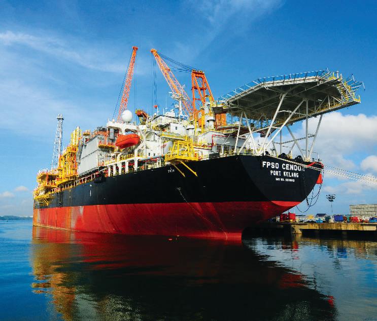
Front Page Photo: MISC’s Cendor Floating, Production, Storage and Offloading (FPSO) courtesy of Malaysian International Shipping Corporation (MISC)
South Korean Best Practice,Applied to Malaysian Ship-Repair and Shipbuilding (SRSB) Industry ....................................................12 Ocean Observation Using Network ODAS Buoy ...................................................................17
Technical Talk on Floating Production, Storage and Ofloading (FPSO) Vessel ..............40
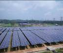
Renewable Power Source: Visit to Amcorp Gemas Solar Power Plant ......................41
TREKKING
Islands and Pulau Layang-Layang
By Captain Ir. Hj. Rani bin Mohd Raji RMN (Retired) Chairman, Marine Engineering and Naval Architecture Technical Division
Captain Ir. Haji Rani, age 68, was formerly a Director of Engineering with the Royal Malaysian Navy and later as Director of Shipbuilding Division at Malaysia Shipyard and Engineering Sdn. Bhd., MSE (now known as MMHE).
Snapshot of Marine Engineering Industry
Of the 60,000 ships that ply the Straits of Malacca annually, only a tiny percentage land in local shipyards for ship-repair services. Our shipyards cater mainly to vessels belonging to the Royal Malaysian Navy (RMN), Malaysia Maritime Enforcement Agency (MMEA) and other government agencies.
Our marine engineering industry has not been able to generate spin-off industries such as spare parts or equipment manufacturing, mainly due to the limited volume in the use of such equipment.
The main challenge is the ability to complete projects on time. Through the Malaysian Industry Government Group of High Technology (MiGHT), Korean specialists were brought in for consultant services. With this arrangement, the refitting and Ship Life Extension Programme (SLEP) of KD Lekir, a RMN Corvette class surface combatant ship, was completed within the 15-month schedule at a local shipyard.
In the commercial ship-building sector, our shipyards are in fierce competition with China though we can compete on building smaller vessels such as anchor handlingtugsandtugboats.Inthepastyears,contractstobuildanumberofvessels for RMN and APMM were awarded to local shipyards. Some yards constructed offshore structures for local and overseas clients. However, with falling oil prices, there are fewer such projects now.
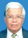
As for research and development, the Marine Technology Centre at Universiti Teknologi, Malaysia (UTM) plays an important role in providing this and testing services to the industry.
DIMENSION PUBLISHING SDN. BHD. (449732-T)
Level 18-01-03, PJX-HM Shah Tower, No. 16A, Persiaran Barat, 46050 Petaling Jaya, Selangor Darul Ehsan, Malaysia. Tel: +(603) 7493 1049 Fax: +(603) 7493 1047 E-mail: info@dimensionpublishing.com Website: www.dimensionpublishing.com
For adverisement placements and subscripions, please contact: DIMENSION PUBLISHING SDN. BHD. (449732-T) at +(603) 7493 1049, or E-mail: info@dimensionpublishing.com
Subscripion Department E-mail: info@dimensionpublishing.com
Printed by
HOFFSET PRINTING SDN. BHD. (667106-V) No. 1, Jalan TPK 1/6, Taman Perindustrian Kinrara, 47180 Puchong, Selangor Darul Ehsan, Malaysia. Tel: +(603) 8075 7222 Fax: +(603) 8075 7333
Mailer
PERFECT
(648839-P)
14 Jalan TSB 2, Taman Perindustrian Sungai Buloh, Sungai Buloh, Selangor Darul Ehsan, Malaysia. Tel: +(603) 6156 5288
JURUTERA MONTHLY CIRCULATION: 36,000 COPIES
Submission or placement of aricles in JURUTERA could be made to the:Chief Editor
THE INSTITUTION OF ENGINEERS, MALAYSIA (IEM) Bangunan Ingenieur, Lots 60 & 62, Jalan 52/4, P.O. Box 223 (Jalan Sultan), 46720 Petaling Jaya, Selangor. Tel: +(603) 7968 4001/4002 Fax: +(603) 7957 7678
Graphic Designer NABEELA AHMAD beela@dimensionpublishing.com
Adverising Consultants ABDUL AZIM BIN SHAARI & THAM CHOON KIT azim@dimensionpublishing.com ckit@dimensionpublishing.com
Accounts cum Admin Execuive YONG YEN YIN yenyin@dimensionpublishing.com
PUBLICATION DISCLAIMER
The publicaion has been compiled by both IEM and Dimension with great care and they disclaimanydutytoinvesigateanyproducts,process,services,designsandthelikewhichmay be described in this publicaion. The appearance of any informaion in this publicaion does notnecessarilyconsituteendorsement by IEMand Dimension. Thereisnoguaranteethat the informaioninthis publicaionisfreefromerrors.IEMandDimensiondonotnecessarilyagree with the statement or the opinion expresssed in this publicaion.
COPYRIGHT JURUTERA Bullein
A Pillar of Malaysian Maritime Industry
by Zoe Phoon
Ir. Prof. Dr Ab. Saman is a Professor in Marine Transport System at the Faculty of Mechanical Engineering and Director of Marine Technology Centre of Universiti Teknologi Malaysia (UTM), Skudai, Johor. He possess 3rd Class Marine Engineers on top of B.Eng, Masters and PhD in various marine related areas. He used to sail on board a ship for a year on internship program and later joining UTM as an academic staff since 1983 until present. He has taught a number of undergraduate courses in the Marine Technology program at UTM including Marine Safety & Environment at the post graduate level. He has been involved in a number of marine related R&D and consultancy projects as well as being in various management positions at UTM.
Malaysia’s only marine hydrodynamics laboratory, Marine Technology Centre located in its Skudai Johor campus in Universiti Teknologi Malaysia, is the second largest in ASEAN region. It is set to do more for the marine industry and economy.
The Marine Technology Centre (MTC) is one of the many research centres in Universiti Teknologi Malaysia (UTM) supporting the university in maintainingitsstatusasaresearchuniversity.Italso carries out consultancy works and short courses to generate income to sustain some of its activities.
MTC’s marine transport management research group focuses on the economic coverage of operations and management of marine transportation, marine safety, marine power plant and sustainable development of the marine transportation system.
On the other hand, the marine and offshore hydrodynamics research group is involved in creating new designs and improving existing designsofmarinevehiclesandoffshorestructures.It specialises in the study of the behaviour and safety of marine vehicles and offshore structures, taking into account their operating environments. Its research covers marine hydrodynamics, dynamics and control, artiicial intelligence and computer simulation.
Oficially opened in 1999, MTC also enables the university’s development of human capital to produce industry-ready graduates in support of Malaysia as a maritime nation.
MAKING RESEARCH PAY
Creating fresh ideas through research and turning them into commercial successes is the key to prosperity for any country. This includes commercialisation of the results of university research.
MTC director Prof. Ir. Dr Ab Saman Abd Kader, who wasinKualaLumpurrecently to attend the annual Industry Advisory Panel (IAP) meeting between UTM and industry professionals, said MTC’s major focus is to carry out research to target the tangible outcomes.
There are plans to expand the hydrodynamics facilities which are currently fully utilised and to make MTC a one-stop referral centre for marine expertise.
Besides publications and intellectual property rights, he said, part of the research outcomes can be commercialised for financial and economic benefits for the industry and the country. On top of that, MTC is also entrusted with the training of postgraduates. A good number of international students are doing postgraduate studies and these have a significant positive economic impact, too.
“Along with its research infrastructure and facilities, we work with the industry and conducts short courses for marine-related companies, which includes providing them with the necessary modules and training packages. These also generate income for UTM,” he said.
Prof. Saman is a professor of marine technology with UTM’sDepartmentofAeronautic,AutomotiveandOcean Engineering of the Faculty of Mechanical Engineering. He was appointed a director of MTC under the Institute of Vehicle Systems and Engineering (IVeSE).
According to him, all academic staff at MTC must, in addition to teaching, also focus on obtaining research grants from both internal and external sources, including international bodies.
Intheprocess,theyhavetocooperate and collaborate with other research partners. At present, MTC is engaged in numerous collaborations with the academia and industry, locally and internationally, in areas of joint research, journal publication, postgraduate supervision and consultancy.
Via memorandums of understanding or memorandums of agreement, UTM is collaborating with institutions of higher education such as Monash University, Universitas Indonesia, University of Southampton, Newcastle University, Kobe University, Hiroshima University, University of Strathclyde Glasgow, Universiti Teknologi Petronas and National University of Singapore.
Meanwhile, MTC’s collaborations with industry include MISC Bhd., Bureau Veritas, Shell, Lloyd’s Register, Technip, Port Tanjung Pelepas, Boustead Heavy Industries Corporation Bhd., Institute of Marine Engineering, Science and Technology (ImarEST) and Wartsila.
On MTC’s consultancy works to date, Prof. Saman said that among the bigger ones are developing the first Malaysian-designed offshore supply vessel with Boustead Heavy Industries, vortex induced vibration (VIV) for vertical tandem riser testing with Shell Malaysia, model tests on the semi-submersible Gumusut with MISC, resistance model tests for 35m patrol boatwithItalthaiMarineLtd.ofThailand,resistancemodel testsfor160ftself-propelledjack-upwithSingaporeAmerin Ltd., and resistance model tests on the 18m cathedral hull vessel with Global Marine Design Pty Ltd. of Australia. Its consultancy works are normally related to design and model tests. For design works, MTC has a number of design software such as Maxsurf (CAD package), Shipflow, Moses, Abaqus, Fluents, Hydrostar (Bureau Veritas), Ariance (Bureau Veritas) and Ansys Aqwa. Finally, it also built the scaled model of the intended ship and offshore structure for hydrodynamics tests at its towing tank facility.
Prof.SamansaidUTMhasaspecificpolicywithregards the commercialisation of research and consultancy initiatives at MTC. He explained: “The income that MTC generates is part of the key performance indicators
The career prospects have been extremely good up till now as most of our graduates are gainfully employed.
(KPIs) that we have to achieve at the research centre. The amount of income generated differs from project to project, and part of that income is used for the maintenance of the facilities to reduce dependence on UTM’s funds.”
The commercialisation of research includes the hovercraft and offshore supply vessel (OSV) and MTC staff members have been involved in the design and construction.
“These products are potentially strategic for Malaysian use. For example, hovercrafts are useful for surveillance and rescue operations in coastal or riverine areas by enforcement personnel while OSVs are used for offshore O&G operations to meet commercial operational requirements,” said Prof. Saman.
“But MTC has produced a lot more research products than just hovercrafts and OSVs. It has designed, produced and tested the ocean wave energy device as well as developed the point absorber energy converter, vertical axis marine current turbine, wave buoy, semi-Swath (small waterplane area twin hull) boat, amphibious boat, wingin-ground vehicle, airboat and so forth.”
TAKING MTC TO NEXT LEVEL
MTC’s marine hydrodynamics laboratory comprises a ship design structure, model making facility, equipment and model testing facility. It is used to support the projects of
undergraduates and postgraduates as well as for UTM staff to do research, consultancy work and conduct short courses.
According to Prof. Saman, MTC is the only place in the country with hydrodynamics facilities and these are currently fully utilised. There are plans for expansion and a working paper is being prepared for submission to the UTM management and the government.
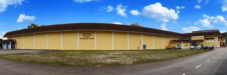
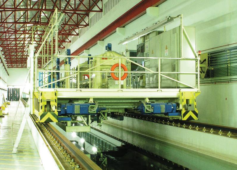
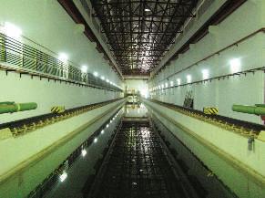
The existing facilities are a towing tank (120m long and 4m wide with a water depth of 2.5m), a towing carriage that tows ship models at speeds of up to 5 m/s, a computer-controlled wave generator capable of generating regular and irregular waves over a wave period ranging from 0.5 seconds to 2.5 seconds, and a data acquisition and analysis system that collects measurement data from the instrumented channels in model test set-ups, stores the measured information and performs preliminary analysis as well as offers realtime onscreen information.
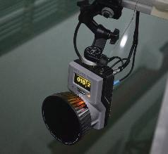
Two other facilities are the planar motion mechanism which consists of two electromechanical actuators that can be mounted vertically or horizontally to the test frame of the carriage, and a motion camera with optical motion capture technology whereby models can remain completely unaffected by heavy sensors, so every small and light model can be used.
“Traditionally, this was accomplished with potentiometer systems attached to a model or with bulky
Towing Carriage
and expensive gyroscopes and accelerometers. Tracking vessel motion under different wave, current or wind conditions, is a fundamental task at a hydrodynamics laboratory or a naval test site. This system makes it easy to obtain accurate 3D and 6DOF positions in realtime,” Prof. Saman explained.
The marine hydrodynamics laboratory also has computer-aided engineering (CAE) facilities. He said the CAE Unit provides services and facilities for intelligent and efficient use of the computing technologies in the ship model testing field at MTC.
This includes providing a variety of resources for researchers and students. The CAE Unit provides access to over 20 types of non-commercial software such as ship hydrodynamics and commercial software. The Computational Fluid Dynamics software has been installed on two super workstations and can be accessed using wireless or wired communication throughout the MTC building.
With its present equipment, he said, MTC offers the following services:
1. Resistance/drag measurements (resistance of a ship model against speed in calm water or in waves. Tests can be conducted in both deep and shallow water).
2. Propulsion tests (thrust and torque against rotational speed of a propeller running behind or in front of a ship model while being towed. The towing force can be measured in calm water or in waves)
3. Fluid flow and body interaction analysis (analysis of fluid flow, measurement of fluid velocity in one direction at an arbitrary location around a model)
4. Sea-keeping behaviour in waves (behaviour of ships inwavesandmeasurementofmotioncharacteristics at different forward speeds).
Other services also offered include ocean and coastal engineering modelling (wave forces acting on fixed and floating structures, and behaviour of structures during float out and installation), manoeuvring simulation (hydrodynamic reaction forces in drift tests or from oscillatory motions forced on the model), lightship survey
(including inclining experiments), stability assessment (stability curve and stability assessment according to standard criteria), design service (hull form design for a specific purpose, and general arrangement drawing), vibration monitoring and mitigation, full scale motion and monitoring (ship motion measurement and analysis, and motion assessment according to standard criteria for ship, equipment and personnel onboard) and full scale powering measurement (sea wave measurement, vibration problem identification and solution, ship motion monitoring and engine torque measurement).
Going forward, Prof. Saman said MTC is planning to raise UTM’s global ranking and profile through obtaining more international research grants to commercialise research products on the international front and by carrying out more joint publications with foreign universities. Plans are also afoot to make MTC a one-stop referral centre for marine expertise.
One of MTC’s roles at present, he said, is to assist the shipping industry in Malaysia where 70,000 ships pass through the Straits of Malacca alone each year. This help can be in the form of R&D, design and testing or education and training of manpower.
“Things can be improved in terms of ship safety in navigation and environmental protection. Through R&D and short courses at MTC, we are playing our role in reducing the risks,” said Prof. Saman.
“For instance, we carry out research on improving the automated ship identification system (AIS) and its operation. MTC also conducts a short course on this for staff members from various marine-related companies. Similarly, staff members and postgraduate students are doing research on the AIS performance.”
CHANGING WITH THE TIMES
Universities around the world are changing with the times and the key factors driving change are globalisation, technology and the growing needs of markets and industries.
UTM had been offering the marine technology programmesince1982atitsKualaLumpurcampusbefore
it moved to its main campus in Skudai. Prof. Saman said UTM, in response to market demand and feedback from stakeholders (including external assessors, professional bodies and industry players) in recent years, replaced that programme with the naval architecture and offshore engineering programme in 2011.
It has continued to receive good feedback from the marine industry, such as those involved in port and shipping, offshore operators, oil and gas (O&G) companies and consultants.
Asked to comment on the observation that there is a need to look into other fields of study as Malaysia reduces its dependency on petroleum, he said the UTM programme remains relevant.
“The country still has a good amount of O&G reserves, at least for the next 20 to 25 years. That will require graduates from our naval architecture and offshore engineering programme in order to minimise reliance on foreign experts in the field,” he said.
“The programme will still be relevant beyond 25 years in producing graduates for ship design and construction as well as repair and maintenance. After all, academic programmes are dynamic and require periodic reviews and improvements.
“The career prospects have been extremely good up till now as most of our graduates are gainfully employed. Some companies even carry out recruitment exercises at UTM among third-year students doing the four-year programme.”
On the public or employer perception that graduates generally lack the necessary skills to meet market requirements, he said that “while this is true in certain areas of employment”, UTM has continuously addressed such concerns via a number of approaches as a result of feedback from the accreditation process and employer surveys.
He noted: “One such approach is our continuous quality improvement (CQI) initiative to improve the curriculum and content of our courses to address the generic skills requirement. In addition, we receive feedback from the IAP which we call on annually to view the curriculum and its implementation, including the standard of the examination Q&A scheme.”
As for market requirements in the marine industry, Prof. Saman said sectors such as port and shipping and offshore O&G specifically require graduates who are able to design and use relevant software such as computational fluid dynamics and finite element analysis, do programming and so forth in their daily work. They are alsorequiredtobeabletocarryoutprojectmanagement in anticipation of the growth in the marine industry.
“The graduates of UTM, particularly from the marine background, are very good, with very promising employability rates even with reputable marine companies. Our curriculum addresses the entire knowledge acquisition process, including soft skills such as leadership, critical thinking, innovation and entrepreneurship,” he said.
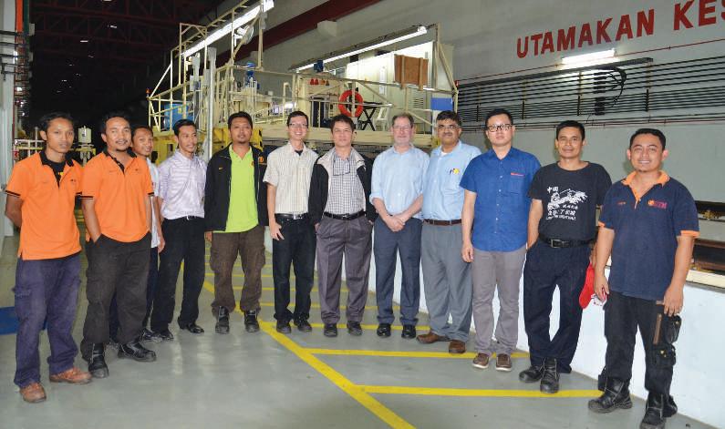
Prof. Saman (6th from right) with staff members from industry partner Technip Geo-Production Sdn. Bhd.
South Korean Best Practice, Applied to Malaysian Ship-Repair and Shipbuilding (SRSB) Industry
First Admiral Dato’ Ir. Ahmad Murad Omar (Rtd) FIEM, FIMarEST, PEng, CEng, MSNAME, AseanEng
First Admiral Dato’ Ir. Ahmad Murad is an accomplished Chartered Marine Engineer (CMarEng) and Chartered Engineer (CEng). Having a career in the marine sector for more than thirty years, Dato’ Ir. Murad has a wide experience in marine consultancy and matters related to shipbuilding and ship repair technology.
At the recent LIMA 2015 exposition in Langkawi, the Malaysian Ship building/Ship Repair Industry Report 2015/2016 was launched by the Minister for MiGHT, Dato’ Mah Siew Keong.
In the report, Prime Minister Datuk Sri Najib bin Tun Haji Abdul Razak wrote: “The SBSR industry must continue to be resilient and maintain its competitiveness. All players must prepare to face the challenges in the next few years until the price stabilises”.
Some of these challenges may be classified as:
• Technology
• New approaches in improving productivity
• Overcoming cost of production
• Improving capability and competency
This article will share a viable approach to improving capability and competency which will then translate into project closure meeting completion date, within cost, at the predetermined time and quality.
A BIT OF HISTORY
About 140 years ago, the shipbuilding and shiprepairindustrywascrudeandbasic.Automation was unheard of and shipyards did not have the sophisticatedtechnologyofmodernday.Almost every piece of work had to be done manually.
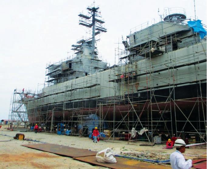
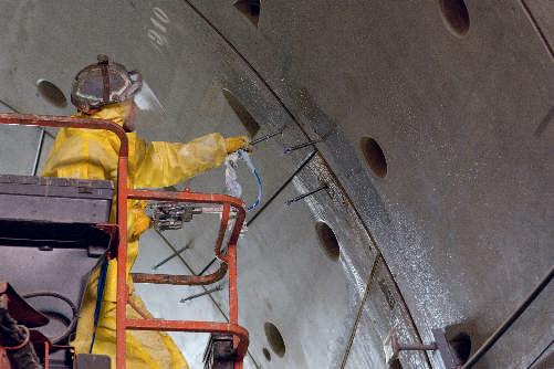
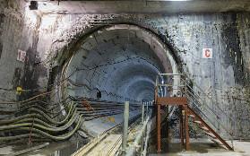
Photo 1: KD Lekir on blocks undergoing SLEP and Reit at the Boustead Naval Shipyard (BNS)
Today, technology has advanced greatly. Automation has improved production time tremendously and the use of machines has enabled finished products that are close to perfection. What used to take 1,000 man-hours 100 years ago, could probably be done now in under an hour. As stated in the SBSR 2015/2016 Report, one of the key strategies to intensify the application of science and engineering in the industry is “to apply local design and adopting new SBSR technologies” .
Looking to neighbouring countries for new trends and approaches to improve production design and work execution, has started and one of the initiatives seen today is the South Korean Best Practice.
In improving efficiency in ship repair projects as well as shipbuilding, a service agreement between Might Meteor Advanced Manufacturing (MMAM) and a subsidiary of Malaysian Industry Government Group for High Technology (MiGHT) was signed. This put into realisation the presence of South Korean specialists in Malaysia to offer consultation services and best practices with regards to ship-repair projects
PRACTICAL TRANSFER OF TECHNOLOGY
The service agreement included bringing in South Korean specialists with years of experience in ship repair and shipbuilding (SRSB) to join the project management team at Boustead Naval Shipyard (BNS). This was in support of the BNS shipyard rationalisation programme where delivery was according to the stipulated completion date, failing which a heavy penalty would be imposed on BNS by the Government.
Complementing the South Korean team were six other Malaysian members of the project team as part of the under study and training of the local complement. The case in point was a ship belonging to the Royal Malaysian Navy (RMN). The KD Lekir, a Corvette Class surface combatant built in Kiel, Germany, in early 1980s, was undergoing refitting and a Service Life Extension Program (SLEP) at BNS.
The team joined the shipyard in November, 2013, and the contract was for 15 months, ending in February 2015, four months after the scheduled completion date of the KD Lekir’s repair programme on 30 October, 2014.
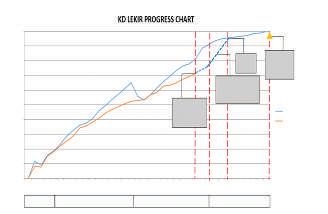
Fig 2: The status of repair progress as at November, 2014
FEATURE
The Malaysian-South Korean team went to work with the shipyard’s project management team (PMT) and began the laborious task of setting the pace for a South Korean Best Practice. The repair work had already started but progress was rather sluggish. (See Photo 1 for status of progress). The chart showed a 12-week delay. At this rate, the shipyard would definitely be slapped with late-delivery charges (LD).
In Fig 2, the blue line is the projected representation and the red line is the actual progress, a delay equivalent of 12 weeks. The task was to gradually bring the gap closer so that, at the end of the project, the result would be the two lines meeting.
In the beginning, the task seemed difficult but under the guidance of the competent South Korean shipyard experts and the experienced locals who had been in the ship-repair industry for more than 20 years, progress was starting to show after the first two months.
BRIDGING THE GAP
Initially, the team (South Koreans and locals) had to understand the current practice at the shipyard in terms of the following:
• the culture and the ability to accept change
• establishing team-working of the South Korean practice
• alignment of processes against objectives and
• optimal utilisation of shipyard strength and capability.
The above helped the team to quickly identify the shortfalls that existed in the current shipyard practice. Once these were established, the next step was to blend the South Korean Best Practice with Malaysian culture, a task that would later prove to be quite a challenge.
APPLYING THE SOUTH KOREAN BEST PRACTICE
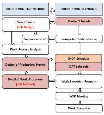
One of the South Korean Best Practice methods is the Zone Out fitting approach. Work flow would be represented in a diagrammatic form (Fig 3). The fundamental action would be to focus on Production Engineering and Production Planning. With these two in place, KD Lekir was classified into divisions called “zones”. The zones were then embedded into the Project Master Schedule (Gantt Chart).
Individual zones would be filled with information that included jobs to be done, in order for the zone to be completed. These jobs included details of outfitting, piping, electrical and HVAC. Against the Gantt Chart, completion dates were identified.
Next was designing the work processes that would be required to be done in each zone, and a production system was drawn up. At this juncture, the Detailed Work Procedure (DWP) was drawn up, indicating exactly what jobs were to be done and the man-days that were required.
Once completed, these elements were processed through the Integrated Hull Outfitting & Painting (IHOP) and Integrated Commissioning And Testing (ICAT). The IHOP took care of the production element and the ICAT took care of the testing and commissioning after the
production process was completed. This dual action resulted in the progressive completion of work done by zone, according to the Project Master Schedule.
Any discrepancy or partially completed job within each compartment belonging to a zone, was listed down in a Punch List and the list pasted on the door of that particular compartment. This way, the project supervisors and lead productionforemencouldquicklyidentifywhatwasrequired to clear the compartment and subsequently, the zone. Using this method, the zones were completed in sequence as according to the Gantt Chart and, as they progressively met completion target dates, the gap of the delay would also gradually close up.
With this approach, work execution became more visible instead of cluttered, as all the jobs within each zone were immediately identified and shortfalls quickly addressed and resolved. However, this feat would not have been accomplished without the other elements of the South Korean Best Practice.
OTHER ELEMENTS ENHANCING THE SOUTH KOREAN BEST PRACTICE
Besides the IHOP and the Zone outfitting, other elements such as the 5S improvement initiative, kaizen (philosophy of continuous improvement), culture evolution and leadership are some other elements that also need to be inculcated in the work-force. Organisation can improve through:
• a clear strategy or objective
• engaged leadership
• motivated work-force and
• effective management tools .
Fig 3: Fundamental Zone Outitting Structure adopted for KD Lekir
Contributing to the success of the project was the clear objective (the ship must be completed and handed over to the RMN by 30 October, 2014) and the top-down drive from the Top Managementat Boustead Head quarters in Kuala Lumpur as well as the Shipyard Director and his Steering Committee. Though initially sceptical about the new initiative, the Management, the Director and the Committee proved to be a great help in ensuring the completion of the project.
At first, the workers couldn’t see the value but coaching and numerous “bans” (a South Korean practice where the foremen and workers gather in the morning before work starts, to discuss what needs to be done and by when, including material short falls they face and how the problem can be alleviated), proved helpful. The walk-about and the walk-the-talk were also South Korean practices that were adopted religiously.
Finally, effective management tools such as project management software and 5S as well as kaizen helped. One obvious fundamental element that accelerated the success story was “leadership” and it was not just top leadership but leadership at all levels that contributed to the success. Without strong dedicated leadership, it would have been impossible to achieve the objective. Leadership is one element that many organisations fail to address.
CONCLUSION
A full 10 days before the deadline of 30 October, 2014, KD Lekir, now a fully operational warship, was successfully delivered back to its owner, the Royal Malaysian Navy. The shipyard was praise for achieving this feat and it also saved on financial costs.
From an engineering stand-point, it is not impossible to accomplish tasks that seem formidable if engineers bring together their experiences and expertise, and as long as they are willing to try and arecommitted to completing the task, with strong leadership guidance.
Leadershipguidancefromthetopdowntoalllevels,works well with implicit integration backed by sound engineering practices and work ethics. In the KD Lekir project, a local shipyard was willing to learn from the South Koreans who had years of experience in the ship repair industry, adopted their Best Practice and adapted it to the local work culture through experienced local engineers.
The new challenge now would be to sustain this.
REFERENCES
[1] Shipbuilding/Ship Repair Industry Report 2015/2016, by MiGHT, Mac 2015, p9
[2] Shipbuilding/Ship Repair Industry Report 2015/2016, by Might, Mac 2015, p 19
[3] ‘General Electric Lean Six Sigma’ presentation, by Amin, 2012
Ocean Observation Using Network ODAS Buoy
by Prof. Dr Mohd. Rizal Arshad
Prof. Dr Mohd. Rizal, B.Eng. (Medical Electronics & Instrumentation), Liverpool University, MSc. (Electronic Control Engineering), PhD (Electrical Engineering –Robotic Vision System), University of Salford, UK is currently the Deputy Dean, School of Electrical & Electronic Engineering, Universiti Sains Malaysia (USM). He and his team is the pioneer of underwater system technology research efforts in Malaysia.
by Herdawatie Abdul Kadir
Herdawatie, B.Eng Electrical (Electronic), (Mechatronic & Automatic Control), M.Eng (Mechatronic), UTM, is a lecturer at Universiti Tun Hussein Onn Malaysia (UTHM) and currently pursuing her PhD at USM, in the ield of Computational Intelligence. She is a member of the Underwater Robotics Research Groups (URRG), USM.
by Mohd. Helmi Abd Majid
Mohd Helmi Bin Ab. Majid graduated from the International Islamic University Malaysia (IIUM), in 2009 in Bachelor of Engineering (Mechatronic). He then pursued his study in Master of Science (Mechatronic Engineering) at the same institution and graduated in September 2012. He is currently a registered PhD candidate at Universiti Sains Malaysia (USM) with specialization in a ield of robotic.
An ocean observing system can be deined as an infrastructure comprising several independent instruments with the ability to collaborate in order to collect relevant and crucial scientiic data for understanding the ocean. This system, serving as a support system and an eye on the ocean, has the following beneits:
i. Maritime economy
ii. Decision making to improve health of the oceans
iii. Reinforcing coastal safety
iv. Safe and rescue
v. Measuring and predicting sea and ocean changes
vi. Providing the environmental information for wide range of sectors
In order to better understand oceans, partnering with more ocean observation programmes will certainly boost the number of information sources. So, integrating ocean observation programmes at numerous locations will enable real time observation by a variety of sectors (government, private sector and academia) on a large area. In fact, the current data on the seas and oceans is very important for understanding the impact on human activities and climate.
Over the past few years, several observing systems have been developed around the world, such as the Global Ocean Observing System (GOOS), US Integrated Ocean Observing System (IOOS), the European Seafloor Observatory Network (ESONET),
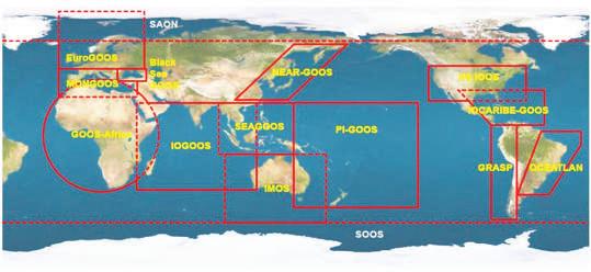
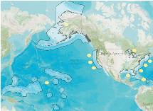
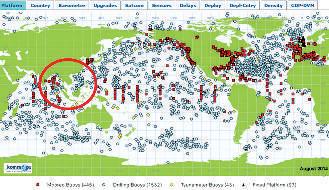
the Australian Integrated Marine Observing System (IMOS), the India National Centre for Ocean Information Services (INCOIS), the Texas Coastal Ocean Observation Network (TCOON), the Southern Ocean Observing System (SOOS), the European Global Ocean Observing System (EuroGOOS), Global Ocean Observing System in the Indian Ocean (IOGOOS), the Mediterranean Ocean Observing system for the environment (MOOSE) and the Monterey Ocean Observing System (MOOS). The overall map of the GOOS partner is shown in Photo 1.
As an example of the integrated ocean observationframework,theU.S.IOOScomprises 11 Regional Associations (RAs) providing ocean data into the framework: i. Alaska (AOOS)
Photo 1: GOOS Regional Alliances Map: The European Global Ocean Observing System (EuroGOOS), Mediterranean Ocean Network GOOS (MONGOOS), Black Sea GOOS, NEAR (North-East Asian Regional)-GOOS, PI-GOOS, Indian Ocean GOOS, IOCARIBE-GOOS, GOOS for Africa, USA IOOS, Southeast Asian GOOS (SEA-GOOS), OCEATLAN , GRASP and IMOS. Other developing regional alliances such as Sustaining Arctic Observing Networks (SAON) and Southern Ocean Observing System (SOOS) [1]
ii. Caribbean (CaRA)
iii. Central and Northern California (CeNCOOS)
viii. Northeast Atlantic (NERACOOS)
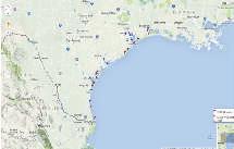
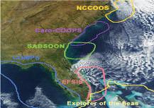
The RAs serve the nation’s coastal communities, as well as the Great Lakes, the Caribbean and the Pacific Islands and territories. The SECOORA programme consists of several alliances such as NCCOOS, Caro-COOPS, SABSOON, COMPS and EFSIS. Photo 2 shows a sample of ocean observation region coverage. There are also observation and data network programmes collecting ocean information such as European Marine Observation and Data Network (EMODnet) [2], Data Buoy Cooperation Panel (DBCP) [3], JCOMM in-situ Observing Platform support centre (JCOMMOPS) [4], Observing system monitoring center (OSMC) [5], National Data Buoy Center (NDBC) [6] and Sea Data Net[7]. These use several platform types such as mooring, drifting, gliders, profiler, argo, ferry box, radar, shore and bottom station.
In the long run, the partnership programmes increase access to greater ocean information and save users time and cost. A better understanding of the oceans can be sampled and compared with a range of platforms. However, such programmes only focus on certain ocean areas as mentioned earlier and there are several areas which still lack ocean observation programmes.
Despite the intensive ocean observation programme networks around the world, certain regions are not covered in the framework. According to Prof. Somkiat Khokiattiwong, Chair of WESTPAC and SEAGOOS, the partnership of ocean observation programmes has helped to mitigate the risk for society and the ecosystem for the regional observation [12].
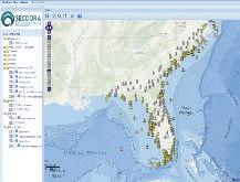
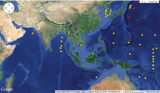
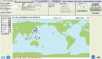
Southeast Asia is still lacking an operational ocean observation programme. To fill the gap, SEAGOOS has introduced two pilot projects – Ocean Forecast Demonstration System (OFDS) and Ecosystem Impacts (MOMSEI) – covering the Malaysian eastern shelf and the Gulf of Thailand. The programme has been successfully initiated and is in progress. Malaysia lacks programmes supporting ocean observation. Photo 3 shows a sample of existing ocean observation platforms in Malaysia.
Malaysia needs an integrated observation system. This is important to understand the trend of coastal and open water seas, which will increase the understanding of long term environmental anomalies. Observation activities as well as internal partnerships between the government, public sector and universities will provide a larger platform network. One way to continuously monitor ocean data is by using scientific buoys known as Ocean Data Acquisition System (ODAS) buoys. Deploying several buoy nodes at potential coastal areas will offer near real-time data of sea water and surroundings. The network buoy will contribute to numerous applications, which will facilitate the continuous understanding of natural processes such as marine forecasting, seasonal forecasting, safety at sea, fisheries and coral reef area resources.
THE OBJECTIVES
The primary objective of a network ODAS buoy is to have an interconnected observation system. A commonly used communication method for a buoy is based on a cellular network with a coverage range that is dependent on transmission frequency and the substation. However, this methodiscostlyfordatatransmissionincontinuousoperation mode.
Alternatively, communication based on radio frequency (RF) communication can be used where unlimited data can be transmitted at minimum cost but this has one drawback, its limited communication range. However, if there is a risk of losing direct communication or unreachable link (for wider operation area) between the ground station and the buoy, an intermediate buoy can act as a hopping point so that the transmitted signal can reach the ground station. This communication is usually bi-directional communication architecture where command is sent to the buoy and buoy transmits the requested data to the shore station. Alternatively, a one directional communication system can be employed if buoys are set to transmit data periodically and continuously to the shore station.
As stated earlier, the network ODAS buoy is used mainly to monitor a wide observation areaand at the end, data is synchronised by a single central station. This is important because Malaysia has a long coastline. So, synchronisation is important for efficient monitoring, data organisation and reinforcement. In addition, the system should be capable of providing sufficient data related to ecosystem observations, including water quality, sea creature behaviour, intruder detection and early warning in case of natural disasters. To achieve this, a sophisticated sensor-and-communication system is essential.
The ODAS buoy system should also be able to withstand an unpredictable ocean and environment condition. In other words, this system should be robust enough to with stand climate changes, wave amplitude and frequency, wind speed, water current, corrosion and weather effects.
SYSTEM ARCHITECTURE
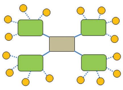
In general, a network buoy consists of multiple buoys interconnected wirelessly. The general architecture of the
(a)
(c)
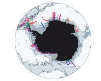
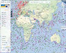
Photo 3: Sample of existing ocean observation platform in Malaysia: (a) Recent data collected form NDBC with program ilter from the NDBC meteorological/ ocean, International partners, IOOS partners, marine METAR, NERRS, NOS/ CO-OPS, oil and gas industry, TAO and Tsunami[6] (b) DBCP[3] (c) OFDS[12]
(b)
network buoy is shown in Photo 4. A buoy collects desired data through the attached sensors and sends the data to the shore station. Shore stations collect data from the buoys wirelessly but are limited to buoys connected to each shore station. The shore stations are positioned nearest to the ocean to enable the wireless transmission from the buoy.
The data is then sent to the central station through internet networking, i.e. cable networking system. The central station is responsible for gathering, processing and storing data from all buoys, collected through multiple shore stations.
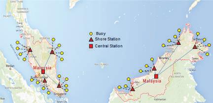
A possible network buoy system for the Malaysian coastal area is illustrated in Photo 5 where the operation and monitoring activities are controlled by the central station in a strategic location and monitored by an authorised organisation. These locations depend on the purpose of the buoy installations, such as monitoring of coral reefs and fisheries.
Since the peninsula and Sabah/Sarawak are separated by a large body of water, a few central stations can be introduced for more efficient ocean monitoring. A buoy system can be separated into a few sub-systems, namely sensor system, mechanical system, power system and communication system. A network buoy is different from a single buoy system only in terms of communication architecture.
Photo 4: General architecture of the network buoy system
Photo 5: Illustration of network buoy implementation
Shore Station
Shore Station
Shore Station
Shore Station
Central Station
A mechanical system consists of body design, mooring design and anchoring design. The most important factor to be considered when designing the mechanical system is the ability of the buoy to withstand the rigorous ocean environment.
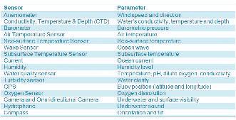
In terms of power supply, buoys are usually powered by batteries which can be recharged through solar energy. On the other hand, a sensor selection is flexible and depends totally on the parameters to be measured, similar to a single buoy system. The most common sensors used for meteorological, oceanographic and water quality parameters are summarised in Table 1. The attachment of the sensor should be according to need. For example, in coral reef areas, sensors for water quality, turbidity and temperature, should be installed to monitor parameters that affect coral life.
Table 1: Common sensors attached to an ODAS buoy
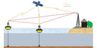
Photo 6: Communication method
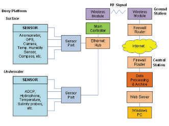
Photo 7: Data transmission architecture
FEATURE
Photo 6 illustrates communication architecture for both cellular and RF communication systems. As stated earlier, RF communication is a preferred choice compared to cellular communication. Because of the shorter range of RF communication,indirectcommunicationcanbeestablished to ensure the signal reaches the shore station. Hopping points are introduced on the buoys located between the shorestation(nearerbuoy)andthetransmittedbuoy(farther buoy) if the direct communication with the shore station is not possible. Details of overall data transmission architecture are shown in Photo 7.
FUTURE PLAN
Anearlyversionofasinglebuoysystemhasbeensuccessfully developedanddeployedinactualworkingenvironments.In thefuture,weplantointegratethemultiplebuoyssysteminto a single network by integrating embedded communication between the buoys and between the buoys and the shore station.
Further research is needed to study the performance of the network buoy in various coastal environments and to identify problems if any. The development of the design and development was initiated by the UCRG, USM. We are also looking for partners to expand our works and new collaborations. This work was funded by the Ministry of Science, Technology and Innovation (MOSTI), e-Science 305/PELECT/6013410 and Universiti Sains Malaysia.
REFERENCES
[1] The Global Ocean Observing System, Retrieved Mei, 14, 2015 from http://www.iocgoos.org/index.php?option=com_content&view=articl e&id=159&Itemid=89&lang=en
[2] The European Marine Observation and Data Network (Emodnet), Retrieved Mei, 14, 2015 from http://www.emodnet-physics.eu/map/)
[3] Data Buoy Cooperation Panel (DBCP), Retrieved Mei, 18, 2015 from http://www.jcommops.org/dbcp/
[4] The JCOMM in situ Observations Programme Support Centre, Retrieved Mei, 18, 2015 from https://www.wmo.int/pages/prog/amp/ mmop/jcommops.html
[5] Observing system monitoring center (OSMC), Retrieved Mei, 19, 2015 from http://www.osmc.noaa.gov/
[6] National Data Buoy Center (NDBC), Retrieved Mei, 19, 2015 from http://www.ndbc.noaa.gov/
[7] Sea Data Net, Retrieved Mei, 15, 2015 http://www.seadatanet.org/
[8] US IOOS, Retrieved Mei, 15, 2015 http://www.ioos.noaa.gov/
Title: One-Day Course on Safety Integrity Levels (SIL) Training For Workshop Participants
10 September 2015
Organisedby :ChemicalEngineeringTechnical Division Time :8.30a.m.–5.00p.m.
CPD/PDP :6.5
Title: 2nd Annual General Meeting of Women Engineers Section, IEM
12 September 2015
Organisedby :IEMWomenEngineerSection Time :8.45a.m.–10.45a.m.
CPD/PDP :2
Title: Professional Interview Workshop (Chemical)
12 September 2015
Organisedby :ProfessionalInterviewBoard Time :2.00p.m.–5.00p.m.
CPD/PDP :2.5
Title: Talk on Coupled Fluid-Particle Modelling of Debris Flow
18 September 2015
Organisedby :GeotechnicalEngineering TechnicalDivision Time :5.30p.m.–7.30p.m.
CPD/PDP :2
Title: One-Day Course on Internet of Things (IOT) for Building and Factory Automation
26 September 2015
Organisedby :MechanicalEngineering TechnicalDivision Time :8.30a.m.–5.30p.m.
CPD/PDP :7.5
Kindly note that the scheduled events below are subject to change. Please visit the IEM website at www.myiem.org. my for more information on the upcoming events.
Shipboard Power Cable Sizing Methodology
by Ir. Mohammad Adnan Sujan
Ir. Mohammad Adnan Sujan, P.E. graduated from Drexel University Philadelphia, USA in Electrical Engineering (BSc. 1998 and MSc. 2001). He has 15 years of working experience in the engineering industry, ranging from manufacturing plant, electrical power plant, nuclear waste and water treatment process treatment plant to the oil and gas industry, covering the onshore, offshore and Floating Production, Storage and Ofloading (FPSO) designs.
One of the most important aspects in the electrical design today is the completion of the interconnection between equipment by the correct/proper selection and use of cables. Depending on the equipment in question, power, control and data transfer protocol become the design necessity in ensuring a high eficiency in power transfer.
In this paper the main discussion will be on the engineering criteria in sizing and selecting low voltage power cables, typically in the range of 0.6/1kV, applied typically for the marine and offshore industry. In the discussion, the design constraints and limitations of usage will focus on the type of cable materials, the core and
No.Conductor IEC 60228 Classification
1.Annealed Copper (Cu) or Aluminium (Al) / Aluminium Alloy
2.Plain or metal coated
ScreenInsulation (Table 1 of IEC 60092-351)
Mica / Glass Tape for Fire Resistant
Thermoplastic Polyvinyl Chloride or copolymer of vinyl chloride and vinyl acetate -PVC/A
Elastomeric or Thermoset Ethylenepropylene rubber (EPM or EPDM) - EPR or halogenfree EPR
3.Aluminium and aluminium alloy conductors, circular or shaped
4.Circular, annealed copper conductors
High Modulus or Hard Grade Ethylene Propylene rubber – HEPR or halogen -free HEPR
Cross-linked polyethyleneXLPE or halogenfree HFXLPE
5.Silicone Rubber – S95 or halogenfree - HF S95
6.Cross-linked polyolefin material for halogen-free cables HF 85
its insulations used in the harsh and corrosive marine and offshore industry.
We will start with the type of power cables normally selected for the industry, followed by its internal and outer construction materials, factored in the external forces influencing the cable sizing calculation design parameters
Filler (Multicore cables)
NonHygroscopic
Moisture resistant
Bedding/Inner Sheath
Thermoplastic PVC (Polyvinyl chloride)
Low Smoke HalogenFree Flame Retardant thermoset compound or EVA
ArmourOuter Sheath (Table 1 of IEC 60092-359)
AWAAluminium wire armour, used in single-core cables
SWASteel wire armour, used in multi-core cables
Copper , Galvanized Steel and Bronze Wire Braids
Aluminium and Galvanized Steel Wire Double Layer Tapes
Thermoplastic compound Polyvinyl chloride or copolymer of vinylchloride and vinylacetate ST 1
Thermoplastic halogen Free SHF 1
Thermoset compound polychloroprene rubber SE 1
chlorosulphonated polyethelene or chlorinated polyethylene rubber SH
Thermoset compound Halogen free SHF 2
and constraints, assumptions, its steady state operation, its resilence and its capability when subjected to the transient operations. The paper will end with the steps taken to do complete power cable sizing calculation and selection analysis and assumptions chosen in the sample calculation. Ship loads can be considered essentials to the personnel on board. This is in addition to the emergency loads applied to ensure safety on-board. Thus, design extreme
In a typical sizing calculation for the electrical equipment, the novelty approach is to subject the equipment to the operational parameters during its lifetime at any site and installed conditions. By the same token, power cable sizing procedure is standardised to the same principles to ensure cables will provide sustainable operability without affecting its performance during its
Basically,powercableconsistsofthincopper(oraluminium)wire,stranded,solid concentric or compacted as per IEC60228 class 2. In the case of emergency uses of the cables, Mica Tape is applied in lieu of the screen, as per the IEC 60331. This type of fire resisting characteristic is defined in such a way that its intended function is to conduct without jeopardising cable integrity under
Based on Table 1 IEC 60092-351, this screen layer is then insulated with one of the insulating materials. Divided into two main material structures, the first is the thermoplastic compound such as PVC. This thermoplastic material is not well received in the design since it has a low steady state and transient state maximum temperature breakdown limits. Preference (or sometimes specified by the electrical designer) is for the use of a second insulation material, the elastomeric material, better known as the thermo set such as cross-linked polyethylene (XLPE), halogen-free XLPE, ethylene propylene rubber, silicone rubber or the cross-linked polyolefin. It is preferable due to the maximum temperature profiles of the materials to maintain integrity during steady state, overload and short circuit conditions. The XLPE can withstand up to 900C during its steady state operation, the maximum temperature of 1300C for the overload condition, and the maximum cable temperature of 3500C in case of short
Referring to Table I of IEC 60092-359, as for the case of single core cable, a layer of halogen-free thermosetting compound SHF 2or halogen-free mudresistant cross-linked compound, SHF mud resistant, is used as the inner covering or inner sheath. This provides mechanical and environmental stresses imposed on the insulated core. Mechanical strength is required due to installation requirements and environmental stress is mainly due to the corrosive and damaging environment. Armour is the choice for providing mechanical protection of the cable for a single core cable. This is normally accomplished by applying either braided tinned copper wire, bronze wire, aluminium wire or galvanized steel wire helically wraps around the insulation. Sometimes, the amour materials can also be of copper, bronze or galvanised steel wire braided
For the multi core cables, low smoke halogen-free, non-hygroscopic materials are added to prevent moisture absorption, as well as to provide fills on the multi conductors arranged and grouped together above. Depending on the standards used and applied as references for the project, cores are coded
Five cores Blue - Brown - Black– Grey - Black
Above 5-cores: Black numbers on white base.
Finally,fortheoutersheath,referringtoIEC60092-359,Table1,amud-resistant, halogen-free thermoset compound, SHF 2, material is applied as the final layer. As standard practice, the colour for the outer sheath is black. In short, Table 1 below illustrates the overall construction and materials of a power cable standardised for the marine and shipboard applications.
3.0 POWER CABLE INSTALLATION REQUIREMENTS
In selecting the best cable for the application, such as for use on the shipboard, the first step is to ensure the cable selected complies with the project requirements. Also refer to the international standards at all times to ensure cables are manufactured and materials used are according to international standards, with design safety margin factored in. The standards to be used are as follows but not limited to, IEC, ANSI, NORSOK, etc. Further analysis involves consideration of the installation requirements such as the installation area ambient temperature and the installation methods applied to the project. In short, the process of selecting the correct power cables, in compliance with standards and requirements, are as follows:
3.3 Identify the environmental requirements for the applications:
a. Ambient temperature (o C)
b. Maximum ambient temperature
c. Termination point temperature limit
d. Coldest temperature
e. Hot spots or presence of heat source such as boilers etc.
3.4 Identify the cable routing and support requirements:
a. Laid on open or closed perforated cable tray
b. Laid on cable ladder
c. Laid against walls
d. Cables bundled with other cables
e. Cables installed with spaces between them
f. In conduits.
3.5 Identify cable installation and pulling requirements:
a. Cable bending radius
b. Cable pulling limit
c. Termination details
d. Multi cable transit availability.
3.6 Identify the cable load requirements its respective fire resistant properties:
a. Normal usage (continuous or intermittent)
b. Standby power application
c. Emergency usage.
3.7 Identify the cable load requirements its respective installation conditions:
a. Mud/oil immersion or corrosive resistance
b. Low smoke requirements
c. Ozone & radiation resistance
d. Water ingress or moisture resistance
e. Explosion and fire area.
In practice, the worst case scenario of each of the conditions above is configured and selected. This will ensure the size limitations, site ambient, transient operating factors and design restrictions are factored in. In other words, the most extreme parameters of the site ambient and installed conditions will become the threshold for the cable design.
4.0 POWER CABLE ELECTRICAL REQUIREMENTS
The calculation steps here are to ensure cables perform as intended without thermal degradation on its insulation during its lifetime. The steps involved in sizing cables based on the conditions section, are:
4.1 Identify voltage levels for the system:
a. High voltage of the ship (i.e. 6.6kV)
b. Low voltage (i.e. 690V, 440V, 400AC)
c. Very low voltage
d. Control system
e. DC system.
4.2 Select number of phases for AC loads:
a. Single phase
b. Three phase
c. DC system.
4.3 Identify the loads the cables are connected to:
a. Generators
b. Motors
c. Variable speed drives
d. Soft starters
e. Heaters
f. Distribution boards
g. Transformers
h. Uninterrupted power supply.
4.4 Identify project requirements:
a. Cable voltage drop
b. Voltage dip at motor control centre bus bars
c. Harmonics contents
d. Terminals
e. Safety requirements, reflective voltage wave issues
5.1 Calculate Load Full Load Ampere (FLA) based on the equipment rated apparent Power (kVA) or Real consumed power (kW) or as provided by the manufacturer:
FLA(A) = Total kVA Eq. 1
SQRT(3) x VLL
FLA(A) = Power (kW) Eq. 2
SQRT(3) x VLL x Eff x PF
Where:
kVA = Apparent Power
kW = Real Power
VLL = Line to line voltage
PF = Power Factor
EFF = Efficiency of the equipment at rated power
5.2 Calculate installed FLA based on Equation 1 or 2 above. In this case, thermal derating factors are applied.
FLA’ = FLA x DF Eq. 3
Where DF = AF x GF Eq. 4
AF = Ambient temperature derating factor
GF = Group of installed cable derating factor
5.3 Cable manufacturers or vendors normally provides cableampacitychartorcablecurrentcarryingcapacity, for the designer to select the cable from the vendor confirmed ampacity table meeting the requirement of 5.2 above.
5.4 Cable shall be designed to operate in steady state conditions and in the limited time of overload conditions. Effectively,thesiteandinstalledampererating,IS (5.2above) shall be less than that of the rating the circuit breaker rating current of the cable protective devices, It. To ensure safe operation of the cable, the selected cable ampere rating, IN must be greater that the two conditions above. In principle, the ampacity rating must comply with the equation shown below:
5.5 Basedontheselectedcableanditsestimatedlength, calculate Voltage Drop during steady state or during motor starting using formula below [Reference 3]:
Three Phase Volt Drop:
√3I(Rc cos Ø - X c sin Ø) L 1000 V3Ø =Eq. 6
Single Phase Volt Drop:
2I(Rc cos Ø - X c sin Ø) L 1000 V1Ø =Eq. 7
DC Circuit:
2I R c L 1000 Vdc =Eq. 8
Where:
R c = Cable AC or DC Resistance of the cable (Ω/km)
X c = Cable Reactance of the cable (Ω/km)
I = Full load or Starting current (A)
L = length of the Cable (m)
Cos (Ө) = Power Factor (per Unit).
The percentage (%) of voltage drop is then calculated to ensure it meets the limit set by the project requirements.
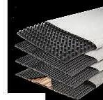
We are a supplier of high quality geosynthetic products used for soft soil stabilization, slope reinforcement, coastal erosion protection, river bank protection, landfills, drainage, road and railway construction.
Our Products:
NEXTILE NON-WOVENS
NEXFORCE HIGH-STRENGTH WOVENS
NEXGRID GEOGRIDS
We also provide design, specification, bill of quantities, cost estimate and drawings free-of-charge. Vd % = (Vd/ VLL) X 100 Eq. 9
5.6 Referring to IEC 60364, the next step involves confirming the selected power cable as a result of maximum short circuit or fault currents. It is a way to check the cable thermal integrity once it is subjected to a high current cable temperature rise and subjected to the maximum short circuit current in a short duration prior to circuit releases either by a circuit breaker or a fuse.
5.7 The calculation focuses on the minimum size of the cable to sustain the short circuit energy that will raise the temperature profile of the cable in a short duration without any thermal degradation and damage. The size shall be sufficient so that the insulation materials and performance are not affected. The formula, captured from reference [3], is given below:
Where:
A =Conductor minimum
i2 t= energy of short circuit (A2 s)
k = Constant from reference [5]
Where:
Өf – Өi are the initial and final conductor temperatures respectively.
5.8 Earth loop can be a separate cable or the cable armour to provide a return path for the earth fault current. In our case, the calculation is to determine the maximum length allowable so that the cable impedance is limited to ensure sufficient current for the protection circuit breaker to operate within the required disconnection time period. The formula for the maximum length is given below [Reference 3]:
L max is the maximum cable length (m)
Vp is the phase to earth voltage at the protective device (V).
IA is the earth fault current required to trip the protective device within the minimum disconnection time (A).
Rc and Re are the ac resistances of the active and earth conductors respectively (Ω/km).
Xc and Xe are the reactances of the active and earth conductors respectively (Ω/km).
No.Steady StateTransient State
1.Full load Ampere (FLA) of the equipment @ installed conditions Short Circuit Current capability (temperature rise)
2.Voltage Drop RequirementsInrush Current (Starting Current)
3.Earth Fault Loop ImpedanceHigh voltage at the terminals due to reflective voltage waveform
4.Overload condition in which Cable Ampacity is greater than that of cable protective device interrupting rating
Lightning induced voltage [Reference 2] Table 2: Cable sizing criteria for the
6.0 SUMMARY
Based on the discussion above, the operational conditions are basically divided into two criteria or scenarios. The first is the cable operation in a steady state and the other is when the cable is subjected to the transient states. Table 2 summarises the criteria of the two operating conditions. For the extreme conditions, the cable intended performance is not affected and the insulation integrity of the cable produces no thermal degradation which can reduce its lifetime and jeopardise safety.
EXAMPLE:
Youaretosizethepowercable,connectingfromtheexisting 400V 50Hz LV switch gear in a 10-year-old DNV certified FPSO to the 250kW three phase motor for the crude transfer pump. Thepowerfactoranditsefficiencyofthemotorareassumed 0.8 and 85% respectively. The starting current is about 6.5X the full load ampere. The motor is located outdoors above the main deck and exposed to the environment. The ambient temperature for some location of the routed cable is, at times, as high as at 50oC. It is protected by the air circuit breaker trip rated at 800A. The length is about 200m from the electrical room in the FPSO electrical room which is located adjacent to the main ship bridge. The FPSO is located in an offshore location north of Borneo oil field.
Step 1:
Check the installation based on the site conditions shown in Section 2 above. The finding is given below:
a) The cable must be DNV classification and the project requirement includes XLPE insulated, armoured and PVC outer sheath.
b) The ambient temperature is 40 degrees Celsius and highest can be at 45 degrees.
c) The cable will be routed with other cables, bundled with other cables.
d) It is for normal process use.
e) It shall meet the requirements of mud resistant and low smoke zero halogen type cable.
Step 2:
Check the electrical requirements based on conditions shown in Section 3 above. The finding is given below:
a) It is LV application 400V AC 50Hz and thus 0.6/1KV insulation type cable is selected.
b) It is three phase motor with separate earthing cable.
c) It must meet less than that of 5% voltage drop at the motor terminal during normal operation.
Step 3:
Calculate the FLA using equation 2 above. The finding is given below:
FLA = 531A
Where KVA = HP x 746
Equation 5
Project requirement may include a minimum size of 25% greater than that of the FLA. The finding is given below:
FLA’= 651.31A
Step 4:
Select power cable that meets the requirements above, from technical data provided by the vendor. Example, a) 2 x 1C x 240 mm sq (1044A) or b) 3 x 1C x 185 mm sq (1332A)
Step 5:
Calculate the FLA applying derating factors, based on Section 4.2 above. The finding is given below:
A. 2 x 240 mm sq: FLA’ = 2 x 522 x 0.95 x 0.78 = 773.6A
B. 3 x 185 mm sq: FLA’ = 3 x 444 x 0.94 x 0.78 = 987A
AF = 0.94 & GF = 0.78
The cable above is selected based on the Section 3 above. In addition cost control, availability and specific project requirements may be considered.
Step 6:
Calculate the overload conditions shown in Section 5.4 above. The finding is given below:
531A ≤ 800A ≤ 987A
Thus, cable (B) meets the conditions of equation [5] above and is selected.
CAUTION: Make sure to also check the space for routing, transits, conduits and airways, tight areas, termination, and bending possibility.
Step 7:
Calculate voltage drop using formula shown on Section 5.5. The finding is given below:
=183.94[(.128 x 0.8) + (.096 x 0.6)]/3
= 29.43 / 3 = 9.8V
Since it is 3 parallel run per phase, then at each run, the drop is 10.8V.
Voltage drop during motor starting, given that:
• Istarting = 6.5 times FLA
• PF is assumed at 0.3 = 3452[(.128x 0.3)+(.096x0.954)]/3 = 9.92%
So, the voltage drops are acceptable as during steady state, is about 1.03% and during starting the % drops is 9.92 %
Step 8:
Then check the cable insulation integrity against the possible short circuit current or faulted current maximum at the cable itself. In this case, equation [10] is applied.
Assuming that Ik is the prospective short circuit current of 25kA, the protection set at 1 sec and by reference [9], with the operating and limit cable temperatures at 250 and 90 degrees C respectively, the temperature rise constant is:
k = 143
Therefore, the minimum size of the cable to sustain the impact of this maximum short circuit current is
A = SQRT [(25000^2) x 1]/143 = 174 mm2
For a 650A earth fault protection with a 3-second opening time, the minimum size of the cable is given below:
A = SQRT [(650^2) x 3]/143 = 7.8 mm2
The selected cables can handle the short circuit thermal transient effect above.
Step 9:
For a separate earthing used for the load, calculate earth fault loop impedance to determine the maximum length for the cable for the earth fault protection Equation 11 above.
Assuming that the earthing cable is 70mmsq cable, taken from equation 12 above, the finding is given below:
Lmax = 454m
REFERENCES
[1] ABB SACE, technical Guide, Electrical installation handbook Protection, control and electrical devices, 6th Edition 2010, Bioni, 3534123 Bergamo Italy
[2] C. Gomes and M. Z. A. Ab Kadir, Protection of Naval System against electromagnetic effects due to lightning, Progress In Electromagnetics Research, Vol. 113, 333{349, 2011, Centre of Excellence on Lightning Protection, Department of Electrical and Electronics Engineering, Universiti Putra Malaysia, Malaysia
Kindly note that the scheduled events below are subject to change. Please visit the IEM website at www.myiem.org.my for more information on the upcoming events.
Robots for Fire Fighting
Ir. Dr Tan Chee Fai is currently Hon Secretary/ Hon Treasurer of Mechanical Engineering Technical Division, IEM Excomm member and IEM Council Member. In addition, he is the Vice Chairman of IEM Malacca Branch. He is also the Senior Lecturer of Faculty of Mechanical Engineering, UniversitiTeknikal Malaysia Melaka. He graduated from Department of Industrial Design, Eindhoven University of Technology.
Fireighting is one of the most hazardous careers in the world. Fireighters need to extinguish ires in hazardous environments, carry equipment and take care of his own safety as well as save ire victims and properties.
According to the statistic by International Association of Fire Fighters (IAFF), the death rate of US ireighters per year, is around 1.9 ireighters per 100,000
structure ires (IAFF, 2000). However, the number is increasing to 3.0 per 100,000 structure ires (Kyle, 2007).
Firefighters die in the line of duty because of burns, falling structures, explosions, crushing injuries and related trauma (Rosmuller and Ale, 2008). In a fire, firefighters can face various kinds of hazards and life threatening conditions including building collapse, corrosive gas, explosion and radio activity. In United Kingdom, Belgium and the Netherlands, firefighters are not allowed to enter burning buildings. This move is to avoid fatalities when firefighters are trapped in the buildings.
Equipment such as helmet, gloves and flat head axe are not enough to protect firefighters from danger. Firefighting techniques and technology must be improved to reduce fatalities among firefighters.
Currently, a lot of research and development is being carried out around the world to develop robots that can assist or replace the firefighter. Different kinds of firefighting robots have been used by fire services departments around the world such as Hong Kong and Singapore. These robots are able to help the firefighter extinguish fires, carry the necessary equipment, search for victims and conduct surveillance in hazardous environments.
Technological advances have also improved firefighting equipment and reduced the rate of fatalities among firefighters. One such advancement is the application of robots.
Different type of robots have been developed and used around the world. The Austrian made LUF60 (NRT, 2013) is a dieselpowered machine equipped with an air blower and a water beam fog. At high speeds, air will mix with the water and turn into fog to help extinguish the fire. The LUF60 can also blow water to a distance of up to 80m.
The FIREROB (American crane, 2012) robot is equipped with a heat shield and high pressure water mist extinguishers to fight fires. The robot can also be installed with a thermal imaging camera and sensors for feedback purposes.
Croation manufacturer DOK-ING (DOKING Company, 2010) has developed a multifunctional 9-ton firefighting robot. This is the biggest long range (1500m) remote control technology GPS-INS (Global Position System –Inertial Navigation System.
JMX-LT50 (Chinawe, 2013) is a remotecontrolled firefighting robot developed by the China manufacturer. It is equipped with a water cannon that can spray water in different angles and for different distances. It uses tyres to move around.
IntheUS,afirefightingrobot, Thermite (Howe and howe, 2013), was developed to fight urban fires, forest fires and industry fires. The Thermite can be controlled from a distance of 400m via a multi-directional monitor; this will ensure the safety of the operator. The Thermite is designed for use in both rough terrain as well as building environments.
The Fukushima Daiichi nuclear plant, which was
Ir. Dr Tan Chee Fai
Photo 1: The robots are designed for use in hazardous environments
damaged by a tsunami, was inspected by a robot named iRobot PackBots (Hornyak, 2011). It was deployed at the nuclear plant to record radiation levels.
MyBOT-X is a remote-controlled machine consisting of a mobile and rigid chassis. It can be controlled wirelessly at distances of up to 500m. Its nozzle can be directed at different angles and even elevated when required, for fighting fires at different heights. The modular-based mobile robot was developed to reduce the risks faced by firefighters when performing their duties.
It is light weight and is equipped with long-range control ability for firefighting and victim search purposes. The robot can be used for surveillance, object clearance, inspection and compound guiding by changing the top part of the robot (Tan et al., 2013).
Photo 1 shows model of the MyBOT-X for hazardous environments. Unfortunately, the current robot is unable to withstand very high temperatures assome of the electrical and electronic components are affected or destroyed by the heat from the fire. To overcome these constraints, the robot may be installed with a heat shield or a sensor system in futurefor protection. Research and development is being carried out to improve the performance and reliability of the MyBOT-X.
MYBOT-X FOR FIGHTING FIRES IN A HAZARDOUS ENVIRONMENT
Although the robot has been developed to replace the firefighter to reduce the risks that the latter faces, a firefighter’s experience and knowledge are invaluable and these cannot be replaced by a robot.
The robot can be deployed in highly hazardous areas such as petrochemical plants, radioactive environment, unstable structures and high pressure vessels.
REFERENCES
[1] International Association of Fire Fighters (IAFF), 2000. Death and Injury Survey, Washington. http://www.iaff.org/HS/PDF/2000%20D&I. pdf. Accessed on 5 September 2008.
[2] Kyle, S.N., 2007. NFPA Releases Fireighter Death Study, U.S.A. http://cms.irehouse.com/content/section/news. Accessed on 5 September 2008.
[3] Rosmuller, N. and B.J.M. Ale, 2008. “Classiication of fatal ireighter accidents in the Netherlands: Time pressure and aim of the suppression activity,” Journal of Safety Science, 46: 282-290.
[4] NRT. http://www.nrt.org/production/NRT/RRT3.nsf/Resources/ May2009ppt2/$File/LUF-60_Presentation_to_ Chiefs-2.pdf. Accessed on 8 Mar 2013.
[5] Americancrane. http://www.americancrane.com/Telerob/Firerob.htm. Accessed on 8 Mar 2013.
[6] DOK-ING. Fireighting (MVF-5). http://www.dok-ing.us/products.html. Accessed on 5 October 2011.
[7] Chinawe. http://www.chinawe.net/html/xf/thxf/20100609_268016. html. Accessed on 8 Mar 2013.
[8] Howe and Howe. http://www.howeandhowe.com/ uploads/1/5/2/4/15246154/rs1-t2_quad_chart.pdf. Accessed on 8 Mar 2013.
[9] Hornyak, T, 2011, Packrobots record video inside Fukushima reactor, http://www.cnet.com/news/packbots-record-video-inside-fukushimareactor/. Accessed on 8 August 2014.
[10] Tan, C.F., S.S.S. Ranjit, V.K. Kher and H.F. Kong, 2013. Up-Scaling and Optimization of Fire Fighting Ground Vehicle Track System. Applied Mechanics and Materials, 315: 236-240.
Chemical Engineering Education in Malaysia
Ir. Prof. Dr Dominic Foo Chwan Yee was the 2012/13 and 2013/14 sessions chairman for CETD, when the survey of ChE education in Malaysia was conducted. He also serves as Malaysia Chapter Chair for IChemE Education Subject Interest Group of the IChemE. He is also the Principle Editor of IEM Journal, and Subject Editor or IChemE Transactions– Process Safety & Environmental Protection (Elsevier). He won the IChemE Innovator of the Year Award 2009, IEM Young Engineer Award 2010, Outstanding Young Malaysian Award 2012, and the SCEJ (Society of Chemical Engineers, Japan) Award for Outstanding Asian Researcher and Engineer 2013.
IT has been 50 years since formal tertiary education on chemical engineering (ChE) started in Malaysia. The irst ChE undergraduate programme was offered at the University of Malaya (UM) in 1974 (IEM, 2013). In the following decade, two other universities also started ChE programmes, i.e. Universiti TeknologiMalaysia(UTM,1983)andNationalUniversityofMalaysia(UKM,1984). Till the late 1990s, ChE graduates did not get much attention among various Malaysian industrial sectors, as there was a lack of understanding on the role and contribution of chemical engineers.
We then witnessed aboost in the chemical industry in Malaysia in 1990s, when many major petrochemical and oleo chemical plants were commissioned. Following this, career opportunities for ChE graduates arose significantly. This led to the exponential increase of ChE Departments as well as number of graduates in the country. The author conducted a survey in 2014 among various higher learning institutions in Malaysia which revealed that there are over 20 universities that offer ChErelated programmes in the country and that there were approximately 2,400 ChE graduates in 2014 (see Figure 1 and details given in Table 1).
Engineers (IChemE) and Engineers Australia (IEAust).
From this, it is clear that approximately each year, a new ChE programme was offered by Malaysian universities in the last two decades (1995-2014), despite the fact that it involved high capital expenditure (mainly due to the teaching and learning facilities including laboratory set-up). There are also foreign university branches that offer some of these programmes in Malaysia, including those from UK and Australia. Recent development shows that a top university from China has also set up its branch here which will offer the ChE programme. Most of these programmes are accredited by the Engineering Accreditation Council (EAC) of the Board of Engineers Malaysia, a few by the Institute of Chemical
As Malaysia has been accepted as the 13th signatory of the Washington Accord on 18 June, 2009 (EAC, 2010), all graduates from EACaccredited programmes after this date are, by default, recognised by the signatories of the Washingtonaccord.Inotherwords,aMalaysian ChE graduate from an EAC-accredited program fulfils the minimum requirements of ABET (US), and is able to sit for the Professional Engineering (PEng) examination in the US.
ROLE OF IEM IN FOSTERING ChE EDUCATION IN MALAYSIA
The two important bodies for promoting engineering profession among ChE community in Malaysia are IEM and the IChemE. Within IEM, the Chemical Engineering Technical Division (CETD) plays an important role in promoting interactions among working professionals and academia. CETD is aware that there is a
Ir. Prof. Dr Dominic C. Y. Foo, M.I.E.M., FIChemE, FHEA, CEng
Figure 1: Number of universities that offer ChE programmes and number of ChE undergraduate students in Malaysia
Malaya (UM)Department
Universiti Teknologi Malaysia (UTM)
(UKM)
Universiti Sains Malaysia (USM)School of
Universiti Putra Malaysia (UPM)Department
Universiti Teknologi Petronas (UTP)
Universiti
MICET)
continuous need to produce highly qualified chemical engineers to support the growth of the chemical industry in Malaysia. In line with this, CETD organises seminars, workshops and activities throughout the year. One of the most important annual events of CETD is the Malaysian Chem-E-Car competition; the 10th competition was held recently in April, 2015, at UKM). The Chem-ECar event attracts the participation of many Malaysian chemical engineering undergraduate students. Participants utilise various alternative fuels (no fossil fuel is allowed!) to move the load carrying the shoe box sized car.
CETD also organises the annual national Research Paper Competition and Chemical Engineering Design Competition. The former is held in conjunction with the Asia Pacific Confederation of Chemical Engineering (APCChE) congress, where CETD represents IEM as a member body. Winning students of the competition are partially sponsored to present their work in the APCChE congresses (New Zealand, 2002, Korea, 2013, Melbourne, 2015).
Chemical Engineering Design Competition was launched in 2012 and three competitions have been held since. It attracts final year students from various universities to compete their capstone design projects. Throughout the competition cycle, several workshops are also held, where CETD committees serve as speakers in delivering various industry-relevant topics such as those related to safety, health and environment.
In a nutshell, CETD is dedicated to the training of future chemical engineers through interaction with current students through such competitions. CETD also assists the Board of Engineers Malaysia in the accreditation of ChE programmes in local universities, as well as to conduct Professional Interview for qualifying candidates to achieve professional status.
On the other hand, the Institution of Chemical Engineers (IChemE), which started its Malaysia Branch since 2006 (IChemE, 2015), has an important role to play in promoting professionalism among ChE academia in the country. They organise two congresses annually, i.e. the Symposium of Malaysian Chemical Engineers (SOMChE), a research-based conference where various research papers are presented, as well as the undergraduate seminar known as National Chemical Engineering Symposium (NACES). Both attract good participation among academics and students. In 2013, the IChemE signed a Memorandum of Understand (MOU) with IEM to foster better collaboration for the ChE community.
LOOKING FORWARD
With the growth of chemical industrial sectors, the growth of the ChE education sector is expected to remain active at least for the next decade. Presently, there remain some challenges faced by the ChE academic community in Malaysia. Limited qualified teaching staff (with PhD degree and sufficient industrial experience) and balancing the load between teaching and research activities are the main challenges that need to be addressed.
ACKNOWLEDGEMENTS
The author acknowledges CETD secretary Nagajothi Sonithiam for assisting in the survey for various ChE programmes in local universities. Feedbacks and assistance from Professor Aziz Raman (University of Malaya, IChemE Malaysia Branch Chairman), Prof. Ramesh Singh (University of Malaya), Mohan Balasingam (IChemE Malaysia Branch) are also appreciated.
REFERENCES
[1] Institution of Chemical Engineers (IChemE, 2015). www.icheme.org/malaysia (accessed Feb 2015).
[2] Institution of Engineers Malaysia (IEM, 2013).JURUTERA. September 2013.
[3] Engineering Accreditation Council (EAC, 2010). www.bem.org.my (assessed April 2015)
Technical Talk on Floating Production, Storage and Offloading (FPSO) Vessel
Sreported by Engr. Shazlan Rahman Grad I.E.M.
Engr. Shazlan Rahman is a corporate member with the Institution of Civil Engineers UK (MICE) and a chartered engineer with the Engineering Council UK (CEng). He has more than 10 years of experience in engineering design and project management. He is a committee member of the IEM Marine and Naval Architecture Technical Division (MNATD) and Oil, Gas and Mining Technical Division (OGMTD).
peaking about oil platforms, many are aware of such structures that sit on the seabed. However, when the demand for oil exploded in the 1970s, floating production systems were found to be more feasible in meeting the demand of oil fields located in deeper waters and far away from shores.
The first oil floating production, storage and offloading (FPSO) vessel was built in Spain in 1977 according to Wikipedia. Worldwide, more than 270 such vessels are in operation as oil FPSO vessels.
In order to expose IEM members to the basic structural design principles of an FPSO vessel, the IEM Marine Engineering and Naval Architecture Technical Division (MNATD) organised a 2-hour talk on March 18, 2015, which was attended by 40 members.
It was chaired by Engr. Shazlan Rahman; the speaker was Dr Venkatesh Raj of Aker Solutions.
Dr Venkatesh started by explaining the advantages of FPSO vessels over traditional fixed offshore platforms. For instance, a FPSO vessel is highly mobile and can be easily
re-deployed to other areas with minimum modifications. This gives a FPSO vessel greater cost advantage in developing marginal fields. In addition, by using a FPSO vessel, there is no need to install new pipelines to transfer crude oil to onshore.
Then he went on to discuss the three building blocks of a FPSO vessel: Topside, hull and mooring system. He explained the functions of each component and how to design each of them. Throughout the talk, Dr Venkatesh made several sketches and pulled out some anecdotes from his previous design experiences.
The talk enabled members’ accessibility to some of the more technically complex designs. It was followed by a question-and-answer session. An obviously appreciative audience fielded many questions as they eagerly wanted to learn more.
As a token of appreciation, Capt. Ir. Rani, the Chairman of the IEM’s MNATD presented a certificate and the book, Engineering Heritage Of Malaysia, to Dr Venkatesh.
A Renewable Power Source: Visit to Amcorp Gemas Solar Power Plant
reported by Ir. Tan Seng Khoon
Ir. Tan Seng Khoon graduated from University Malaya in 1974 and worked in JKR for 18 years, being the District Engineer in Kuala Kubu Bahru and later on, in Taiping. At present, he is the Managing Director of Tasek Jurutera Perunding, a Civil Engineering consulting company specializing in Structures, Civil Engineering, Highway and Transportation. He possesses also a keen interest in Information and Computer Technology. He is a committee member in the Information and Communications Technology Special Interest Group, IEM. He was also its group chairman some years ago.
Rapid development from across the world causes global warming and this is a major concern for many environmentalists. The other concern is the rapid depletion of nonrenewable power sources such as fossil fuels (oil, gas and coal).
It is our responsibility, therefore, to find alternative power sources that will make us less reliant on fossil fuels.
Solar energy is energy from the sun. It is a renewable source of energy and power. With conversion, the sun’s energy can be used to light our homes and generate electricity.
With this in mind, a trip was arranged on 5 August 2015, for 46 members of IEM to Armcorp Gemas solar power plant, in Gemas, Negri Sembilan, which harnesses the sun’s energy through modern technology such as photovoltaic.
We arrived at 11.00a.m. and was given a briefing by Dato Khamis Mohd Masin, the CEO of Amcorp Properties Bhd.
This solar power plant is the largest single site solarpowerplantinMalaysiaandhassuccessfully been running since June 2013. The supply and deliveryof10.25MWrenewableenergyfromsolar photovoltaic, for a feed-in-tariff of 80 sen/kWh is for a concession period of 21 years.
Proximity results in savings. Being located adjacent to TNB’s 11kV power transformer substation is an advantage for the solar farm. This has resulted in considerable benefits to Amcorp as there are significant cost savings on the inter connection expenses between the solar plant and the transformer substation.
The solar farm, spread over 35 acres, was built at a cost of RM87 million. It is capable of producing 41,000 kWh of electricity each day to fulfill peak-hour demand.
The plant has been installed with 41,076 solar panels, generating an average of 1.2 million kWh of electricity monthly. The solar panels, known as “Yingli Polycrystalline 250 watt”, are made in China.
The solar cells produce electricity in DC to 33 volts. The DC current is collected and
converted to AC 415 Volt by inverters located along aisles. Thereafter, the AC current is processed in equipment plants in the farm solar powerhouse and then stepped up to 11 KVolt before the current is injected into the TNB grid in the TNB substation.
This energy conversion is an alternative power source made accessible in line with the Government’s effort to promote sustainability in development.
GLOBE TREKKING
Spratly Islands and Pulau LayangLayang
Chin
is a retired civil engineer who derives a great deal of joy and satisfaction from travelling to different parts of the globe, capturing fascinating insights of the places and people he encounters and sharing his experiences with others through his photographs and writing.
China’s ongoing land reclamation works on Zamora Reef, Mischief Reef,FieryCrossandtwoother reefs in the disputed Spratly Islands in South China Sea haveraisedmanyaneyebrow and protests, in particular from The Philippines and USA.
Spratly Islands consist of more than 750 reefs, atolls, cays, islets and islands, with a combined land area of only about 4sq.km. and spread over an area of more than 425,000sq.km. Surrounding countries, i.e. China, Taiwan, The Philippines, Vietnam, Brunei and Malaysia, all lay claim to all or parts of the Spratly Islands, turning the region into one of the most hotly contested regions in the world. All except Brunei have already taken measures to occupy some parts of the Spratly Islands.
The Spratly Islands are economically and strategically important. It is generally believed that the area holds potentially significant oil and natural gas reserves. In addition, the area is a productive fishing ground, sees heavy commercial shipping traffic and, should a country’s claim be recognised, would boost its continental shelf substantially.
Our country lays claim to a small number of islands in the Spratly Islands that fall within our exclusive economic zone of 200 miles as defined by the United Nations Convention on the Law of the Sea. Our navy currently occupies 3islands–SwallowReef(PulauLayang-Layang), Ardasier Reef (Terumbu Ubi) and Mariveles Reef (Terumbu Mantanani).
Pulau Layang-Layang is about 300km north-west of Sabah. It is actually part of an oval-shaped atoll that measures 7km in length and 2km in width. About 3km of the coral reef becomes exposed when the tide is low.
Our government reinforced our sovereignty claim over the island by erecting a signboard on the coral reef in the middle of 1980. Three years later, land reclamation work started to
construct a permanent island over part of the atoll. In April 1986, our navy established a station on the 1.2km long x 200m wide island. In 1991, a holiday resort was built on the island. The island soon became a very popular diving destination in the South China Sea.
I first landed on Pulau Layang-Layang on the eve of Merdeka Day in 1997. I had gone there with two diving buddies to explore the undersea world around the island. Five years later, I made a second trip to that remote island. This time, our group had expanded to 15.
We flew from Kota Kinabalu in a 22-seater twin-propeller airplane which took just one hour to cross the sea. The air-strip occupies half the island longitudinally. The other half was occupied by the resort in the centre, flanked by the naval station on one side and a seabird rookery on the other. When my friends and I were not in the water, we spent a lot of time watching and interacting with the thousands of seabirds. We had a great time on the island.
The vast majority of the visitors to Pulau Layang-Layang are scuba divers; most of them are Europeans and Japanese. Malaysians only constitute about 10% of the visitors.
It is already 13 years since I last set foot on Pulau Layang-Layang. I really miss the colourful marine world and seabird colony there.
Ir. Chin Mee Poon www.facebook.com/ chinmeepoon
Ir.
Mee Poon
To All Members,
Tarikh: 10 August 2015
SENARAI CALON-CALON YANG LAYAK MENDUDUKI TEMUDUGA PROFESIONAL TAHUN 2015
BerikutadalahsenaraicalonyanglayakuntukmendudukiTemuduga Profesional bagi tahun 2015.
Mengikut Undang-Undang Kecil IEM, Seksyen 3.8, nama-nama seperi tersenarai berikut diterbitkan sebagai calon-calon yang layak untuk menjadi Ahli Insitusi, dengan syarat bahawa mereka lulus Temuduga Profesional tahun 2015.
Sekiranya terdapat Ahli Korporat yang mempunyai bantahan terhadap mana-mana calon yang didapai idak sesuai untuk menduduki Temuduga Profesional, surat bantahan boleh dikemukakan kepada Seiausaha Kehormat, IEM. Surat bantahan hendaklahdikemukakansebulandaritarikhpenerbitandikeluarkan.
Ir. Yam Teong Sian Seiausaha Kehormat, IEM,
PERMOHONAN BARU NamaKelayakan
KEJURUTERAAN AWAM
ENG BOON CHENGBE HONS (UTM) (CIVIL, 2002)
MOHD LUKMAN BIN MAMATBE HONS (UTM) (CIVIL, 2004)
MUNIR NAZMI BIN MOHAMEDBE HONS (USM) (CIVIL, 2006)
50720 JEYACHANDRAN BARNABAS A/L G.JESUDASON BE HONS (UTM) (MECHANICAL, 1995)
50208 MUHD ASYRAF BIN ABD AZIZ BE HONS (UTM) (MECHANICAL, 2008)
30631SURESH KUMAR A/L MUNUSAMY REDDIE BE HONS (UTM) (MECHANICAL, 2003)
KEJURUTERAAN STRUKTUR
45311YEE MING JIUNNBE HONS (BRADFORD) (CIVIL & STRUCTURAL, 2008) ME (BRADFORD) (CIVIL & STRUCTURAL, 2008)
PERMOHONAN BARU MENJADI AHLI NamaKelayakan
KEJURUTERAAN ELEKTRIKAL
LAU HENG TIEN BE HONS (UNITEN) (ELECTRICAL POWER, 2005)
Pengumuman yang ke-84
SENARAI PENDERMA KEPADA WISMA DANA BANGUNAN IEM
Institusi mengucapkan terima kasih kepada semua yang telah memberikan sumbangan kepada tabung Bangunan Wisma IEM. Ahli-ahli IEM dan pembaca yang ingin memberikan sumbangan boleh berbuat demikian dengan memuat turun borang di laman web IEM http://www.iem.org.my atau menghubungi secretariat di +603-7968 4001/5518 untuk maklumat lanjut. Senarai penyumbang untuk bulan Julai 2015 adalah seperti jadual di bawah:
NO.NO. AHLINAMA
1.20562ABD. RAHMAN BAKAR @ OMAR
2.18303CHEAH BENG EE
3.04800 CHUA BOON TIONG
4.52367FARID BIN MOHAMAD AMIRUDDIN
5.70423MD JAZLI BIN MD JOHARI
6.49900MOHAMAD BADRI BIN MUHAMAD ZAINI
8.05043 NG YONG KONG
9.01350P'NG CHOON NGAN
10.69499 SIM WEI TAT
11. 32918YUSUF BIN ZUBIR
12.07501ZAHRI BIN JIMAN
13.15123ZAINOLARIFEN BIN SAID
CALL FOR NOMINATIONS
IEM ENGINEERING HALL OF FAME AWARD 2016
The Sub-Commitee of Engineering Hall of Fame under the auspices of the Standing Commitee on Professional Pracice is proud to invite nominaions for the IEM Engineering Hall of Fame Award 2015.
It is imely and expedient to induct and to recordtheaccomplishmentsofengineersin the country who have or had demonstrated paricularly outstanding professional achievements and provided excellent services to the Insituion, the engineering industry and the Naion.
The IEM Engineering Hall of Fame is established with the aim to confer recogniion and to celebrate the accomplishments of members of the IEM:
• Who have demonstrated outstanding professional achievements.
• Whohavemadesigniicantcontribuions to the engineering profession, the Insituion of Engineers, Malaysia (IEM) and the Naion.
• Who have rendered valuable service to the Community.
The Engineering Hall of Fame will serve as the focal point or showcase of outstanding Malaysianengineers,pastandpresent,who hadorhavemadegreatcontribuionstothe engineeringprofessionandtothequalityof life in Malaysia. Engineers honoured in the Engineering Hall of Fame will also serve as a beacon and as role models for young
engineers as well as create greater interest in engineering in general and awareness of the contribuions made by outstanding engineers in the country.
Nominaions for the Award are open to Malaysian ciizens who are or have been Corporate Members of the IEM.
The closing date for receipt of nominaions for IEM Engineering Hall of Fame Award is 30 September 2015.
The nominaion form can be downloaded from the IEM website www.myiem.org.my. For further details, kindly contact IEM Secretariat at 03-7968 4001/2
IEM AWARD FOR CONTRIBUTIONS TO THE ENGINEERING PROFESSION IN MALAYSIA 2016
To encourage an interest in engineering and to recognise important services or contribuions to engineering in Malaysia, the IEM Award for Contribuion to the Engineering Profession in Malaysia is to be presented to the person(s), who has:
• Contributed to the advancement of engineering in Malaysia, and/or
• Designed and constructed an original engineering device or system of merit and applicability to industry.
This Award is open to all Malaysian ciizens and permanent residents.
NOMINATIONS
• Nominaionswillbeinvitedannually.The closing date for receipt of nominaions for each year is 30 September.
• Nominaions shall be made through a member of the Insituion. Each memberisrestrictedtoonenominaion per year.
• Each nominaion shall be accompanied by a brief write up of the services rendered or contribuions made or system designed and/or constructed togetherwithrelevantphotographsand other documents.
AWARD
• The Award is to be made by the Council upon recommendaion by the Awards Commitee.
• The Award shall comprose a metal plaque, a scroll and a sum of RM1,000. The closing date for nominaions is 30 September 2015
Please submit nominaions to:
Hon. Secretary The Insituion of Engineers, Malaysia Bangunan Ingenieur, Lots 60&62 Jalan 52/4, Petaling Jaya, Selangor.
The nominaion form can be downloaded from the IEM website at www.myiem.org.my
IEM OUTSTANDING ENGINEERING ACHIEVEMENT AWARD 2016
The IEM Outstanding Engineering Achievement Award is created to confer recogniion to an organisaion or body for outstanding engineering achievements within Malaysia. The award will be given to an organisaion or body responsible for an outstanding engineering project in the country.
The basis for the award shall be an engineering achievement that demonstratesoutstandingengineeringskills which has made a signiicant contribuion to the profession and to the quality of life in Malaysia. In making the selecion, the following criteria will be given special consideraion:
1. Contribuiontothewell-beingofpeople and communiies,
2. Resourcefulness in planning,
3. Creaivity in the soluion of design problems,
4. Pioneering use of materials and methods,
5. Innovaions in planning, design and construcion,
6. Unusual aspects and aestheic values.
Engineering achievements which include, interalia,thefollowingcanbesubmitedfor consideraion:
• Bridges,Tunnels,WaterwaysStructures, Roads
• Telecommunicaions of naional/ internaional character, Power Transmission and Transportaion
• Dams and Power Staions
• Ports and Harbours
• Building and Structures
• Airports
• Water Supply, Waste Disposal Projects
• Military projects such as bases, launching units, harbour faciliies
• Drainage, Irrigaion and Flood Control Projects
• Local design and manufacture of high technology products
• Energy, Heat, Mass Transfer
• Outstanding work in engineering research and development
• Chemical processing of indigenous raw resources such as rubber, palm oil and
various other local plants
• Innovaive use of local engineering materials
• Outstandingcontribuioninengineering educaion
• Original discovery of useful engineering theory
Nominaionsareinvitedfromallmembersof the Insituion. Each nominaion submited shouldcontainabriefsummary/write-upof the project in approximately 1,000 to 2,000 wordstogetherwithfullrelevantreportson the project and three copies of supporing documentaion including photographs. A project or component part thereof which has received an earlier award, from IEM does not qualify for nominaion.
The closing date for nominaions is 30 September 2015.
The nominaion form can be downloaded from the IEM website at www.myiem.org.my
IEM YOUNG ENGINEER AWARD 2016
(On behalf of IEM, the YES-G&S Committee is proud to invite nominations for the YOUNG ENGINEER AWARD for year 2016)
TheobjeciveoftheAwardistoencourage interest in engineering and to recognise potenial among young engineers in Malaysia. The Award will be presented to the person who has shown outstanding ability and leadership qualiies, either
i. in the design and/or construcion of an engineering device or system of merit; or
ii. in the research and development or teaching of engineering.
In any one year, the Award may be made in either one or both of the categories menioned above. If the Award is to be madeinonlyoneofthetwocategorymay
bemadeintheyear.TheAwardisopento candidate who are:
i. Registered member with the Board of Engineers, Malaysia and under 35 years of age
ii. Malaysian ciizens or permanent residents of Malaysia
iii. Graduate or Corporate Members of IEM.
Photocopies are allowed. The closing date for nominaions is 30 September 2015.
TheProposermayormaynotbeamember of IEM. However, each nominaion shall be supported by a brief recommendaion
IEM WOMAN ENGINEER AWARD 2016
from two Referees who are Corporate members of IEM. If the Proposer himself isaCorporatememberofIEM(orhigher), then he may also act as one of the two required Referees.
Future nominaion will be invited biannually.
The Award will comprise a cash prize of RM500.00, a scroll and plaque, to be presented with due ceremony to each recipient of the Award.
The nominaion form can be downloaded from the IEM website at www.myiem. org.my
The Women Engineers Secion is proud to invite nominaions for the Woman Engineer Award 2016.
The primary objecive of the Award is to recognise the contribuions by women engineers. This Award may also incidentally encourage interest in engineering among women and encouragethemtostrivetowardsgreater excellence. The Award will be presented to the woman engineer who has shown outstanding ability and leadership qualiies, or has been a pioneer in any more of the following areas:
• In the design and/or construcion of an engineering device or system, structural system, planned development, environmental improvements or,
• In the research and development of engineering device, systems, processes and/or materials, publicaion of paper or,
• In the teaching of engineering or,
• In the management of engineering projects,
• Entrepreneurship in the commercial sector.
In making the selecion, the following criteriawillbegivenspecialconsideraion:
• Contribuion to the well-being of people and communiies
• Resourcefulness in planning and in the soluion of design problems
• Pioneering in use of materials and methods
• Innovaions in planning, design and construcion
• Unusual aspects and aestheic values
The Award is opened to candidates who are:
• Registered members of the Board of Engineers, Malaysia,
• Malaysian ciizens or permanent residents of Malaysia,
• Graduate or Corporate Members of TheInsituionofEngineers,Malaysia.
The closing date for nominaions is 30 September 2015. Please submit nominaion to:
The Insituion of Engineers, Malaysia Bangunan Ingenieur, Lots 60&62 Jalan 52/4, P.O. Box 223 (Jalan Sultan) 46720 Petaling Jaya, Selangor.
The Proposer may or not be a member of IEM or BEM, or an engineer. However, each nominaion shall be supported by a briefrecommendaionfromtwoReferees who are Graduate or Corporate member of IEM. If the Proposer is herself either a Corporate or Graduate member of IEM (or higher), then she may also act as one of the two required Referees.
The nominaion form can be downloaded from the IEM website at www.myiem. org.my
CONTRIBUTIONS TO WISMA IEM BUILDING FUND
RM 2,687,094.52 contributed by IEM Members and Committees RM 741,502.00 contributed by Private Organisations
TOTAL RM 3,428,596.52 (ANOTHER RM 3,818,359.90 IS NEEDED)
The Insituion would like to thank all contributors for donaing generously towards the IEM Building Fund HELP US TO PROVIDE BETTER SERVICES TO YOU AND TO THE FUTURE GENERATION (The donaion list to the Wisma IEM Building Fund is published on page 45)
KEAHLIAN
PERMOHONAN BARU / PEMINDAHAN AHLI
PersidanganMajlisIEMyangke-398pada 27Julai2015 telahmeluluskansebanyak 2,490 ahliuntukpermohonanbarudanpermindahan ahli. Berikut adalah senarai ahli mengikut disiplin kejuruteraan: