Suite 29, 3A Floor, IOI Business Park, 1 Persiaran Puchong Jaya Selatan, Bandar Puchong Jaya, 47170 Puchong, Selangor Darul Ehsan, Malaysia. Tel: +(603) 8070 9949 Fax: +(603) 8070 0047 Email: info@dimensionpublishing.com Website: http://www.dimensionpublishing.com
Chairman ROBERT MEBRuER
CEO/Publisher PATRICK LEuNG patrick@dimensionpublishing.com
General Manager SHIRLEY THAM shirley@dimensionpublishing.com
Graphic Designer LEE AI TING art@dimensionpublishing.com
Accounts cum Admin Assistant HO HWEE YEE accs@dimensionpublishing.com
For advertisement placements and subscriptions, please contact: dimension P ublishing sdn. bhd. (449732-T) at +(603) 8070 9949, or Email: info@dimensionpublishing.com
Subscription Department Email: subscription@dimensionpublishing.com
Printed by
hoffset P rinting sdn. bhd. (667106-V)
No. 1, Jalan TPK 1/6, Taman Perindustrian Kinrara, 47180 Puchong, Selangor Darul Ehsan, Malaysia. Tel: +(603) 8075 7222 Fax: +(603) 8075 7333
Jurutera m onthly c irculation : 25,000 co P ies
Submission or placement of articles in JuRuTERA could be made to the:Chief Editor THE INSTITuTION OF ENGINEERS, MALAYSIA, Bangunan Ingenieur, Lots 60 & 62, Jalan 52/4, P.O. Box 223 (Jalan Sultan), 46720 Petaling Jaya, Selangor. Tel: +(603) 7968 4001/4002 Fax: +(603) 7957 7678 Email: pub@iem.org.my or sec@iem.org.my IEM Website: http://www.MyIEM.org.my
Number 9, September 2011 IEM Registered on 1 May 1959
Majlis Bagi s esi 2011/2012 (ie M Coun C il s ession 2011/2012)
Yang D I p E rtua / p r ESIDE nt:
Ir. Chen Kim Kieong, Vincent
tI mbalan Yang D I p E rtua / D E put Y p r ESIDE nt:
Ir. Choo Kok Beng
n a I b Yang D I p E rtua / V I c E p r ESIDE nt S:
Ir. Prof. Dr Ruslan bin Hassan, Y.Bhg. Dato' Ir. Hj. Abdul Rashid bin Maidin, Ir. Lee Weng Onn,
Ir. P.E. Chong, Y.Bhg. Dato' Ir. Lim Chow Hock, Ir. Prof. Dr Wan Mahmood bin Wan Abdul Majid, Ir. Yim Hon Wa
S E t I au S aha K E hormat / h onorarY S Ecr E tarY:
Ir. Prof. Dr Lee Teang Shui
bE n Dahar I K E hormat / h onorarY t r Ea S ur E r:
Ir. Assoc. Prof. Dr Chiang Choong Luin, Jeffrey
Wa KI l aWa m / c IVI l rE pr ESE ntat IVE: Ir. Gunasagaran a/l Kristnan
Wa KI l mEK an IK al / mEchan I cal rE pr ESE ntat IVE: Y.Bhg. Dato' Lt. Gen. (R) Ir. Ismail bin Samion
Wa KI l El EK tr IK / El Ectr I cal rE pr ESE ntat IVE:
Ir. Mohd. Aman bin Hj. Idris
Wa KI l Stru K tur / Structural rE pr ESE ntat IVE: Ir. Yam Teong Sian
Wa KI l K I m I a Dan D ISI pl I n l a I n / c h E m I cal a n D oth E r S rE pr ESE ntat IVE:
Ir. Razmahwata bin Mohamad Razalli
Wakil lain-lain displin / Rep R esentative to othe R disciplines:
Ir. Assoc. Prof. Dr Cheong Kuan Yee
Wa KI l m ult I m EDI a / m ult I m EDI a rE pr ESE ntat IVE:
Ir. Noor Iziddin Abdullah bin Hj. Ghazali
ahl I majl IS / c ounc I l mE mb E rS:
Ir. Prof. Dr Lee Sze Wei, Ir. Tuan Hj. Mohd. Ali bin Yusoff, Ir. Yee Yew Weng, Ir. Mah Soo, Ir. Dr Ahmad Anuar bin Othman, Ir. Kok Yen Kwan, Ir. Yau Chau Fong, Ir. Wong Chee Fui, Ir. Mohd. Khir bin Muhammad, Y.Bhg. Dato' Ir. Hj. Mohd. Isa bin Hj. Sarman, Ir. Assoc. Prof. Dr Marlinda binti Abd. Malek, Ir. Zainuddin bin Mohammad, Ir. Lai Kong Phooi, David, Y.Bhg. Dato' Ir. John Chee Shi Tong, Ir. Gopal Narian Kutty, Ir. Tan Yean Chin, Y.Bhg. Dato' Ir. Ahmad Murad bin Hj. Omar, Ir. Ng Shiu Yuen, David, Ir. Kim Kek Seong, Ir. Chong Chew Fan, Ir. Dr Tan Kuang Leong, Ir. Lau Yuk Ma, June, Ir. Dr Norlida binti Buniyamin, Ir. Ishak bin Abdul Rahman, Ir. Hoo Choon Sean, Y. Bhg. Dato Ir. Samsuddin bin Ismail ahli majlis / council m embe Rs (by a ppointment):
Dato' Ir. Hj. Mohamad bin Hj. Husin, Ir. Abdul Ghani bin Hashim, Ir. Abdullah bin Isnin
bEK a S Yang D I p E rtua tE ra K h I r / Imm EDI at E pa S t p r ESIDE nt:
Y.Bhg. Academician Dato' Ir. Prof. Dr Chuah Hean Teik
b EK a S Yang DI p E rtua / pa S t p r ESIDE ntS:
Y.Bhg. Dato' Ir. Pang Leong Hoon, Y.Bhg. Academician Dato' Ir. (Dr) Hj. Ahmad Zaidee bin Laidin, Ir. Dr Gue See Sew, Y.Bhg. Datuk Ir. Prof. Dr Ow Chee Sheng, Y.Bhg. Dato' Paduka Ir. Prof. (Dr) Keizrul bin Abdullah
p E ng E ru SI caWangan / branch cha I rman:
1. Pulau Pinang – Ir. Ng Sin Chie
2. Selatan – Ir. Mohd. Khir bin Muhammad
3. Perak – Ir. Chan Hoong Mun
4. Kedah-Perlis – Ir. Hor Tek Lip
5. Negeri Sembilan – Ir. Mohammed Noor bin Abu Hassan
6. Kelantan – Ir. Hj. Roslan bin Abdul Azis
7. Terengganu – Ir. Mohd. Azmi bin Ali
8. Melaka – Ir. Mohd. Khalid bin Nasir
9. Sarawak – Ir. Tan Khiok Chun, Alan
10. Sabah – Ir. Teo Chee Kong
11. Miri – Ir. Ting Kang Ngii, Peter
ahl I jaWatan Kua S a I n F orma SI Dan p E n E rb I tan / S tan DI ng comm I tt EE on I n F ormat I on an D publ I cat I on S 2011/2012: Pengerusi/Chairman cum Chief Editor: Y. Bhg. Dato' Ir. Hj. Abdul Rashid bin Maidin Naib Pengerusi/Vice Chairman: Ir. Prof. Dr Lee Sze Wei Setiausaha/Secretary: Ir. Lau Tai Onn Ketua Pengarang/Chief Editor: Ir. Prof. Dr Lee Sze Wei Pengarang Buletin/Bulletin Editor: Ir. Ong Guan Hock
Prinsipal (Jurnal)/Principal Journal: Ir. Assoc. Prof. Dr Marlinda binti Abdul Malek Pengerusi Perpustakaan/Library Chairman: Ir. CMM Aboobucker Ahli-Ahli/Committee Members: Ir. Yee Thien Seng, Ir. Tan Yean Chin, Ir. Chin Mee Poon, Ir. Prof. Dr Mohd. Saleh bin Jaafar, Ir. Hj. Look Keman bin Sahari, Ir. Mohd. Khir bin Muhammad, Ir. Yee Yew Weng, Y. Bhg. Datuk Ir. Prof. Dr Ow Chee Sheng, Ir. Cheong Loong Kwong, Allen, Ir. Prof. Dr Arazi bin Idrus, Ir. Tey Choo Yew, Calvin, Engr. Abi Sofian bin Abdul Hamid, Engr. Shuhairy bin Norhisham, Engr. Abul Aswal bin Abdul Latiff
IEM Secretariat: Nor Aziah Budin, Nurul Aida Mustafa
the institution of engineers, M alaysia
Bangunan Ingenieur, Lots 60 & 62, Jalan 52/4, P.O.Box 223, (Jalan Sultan), 46720 Petaling Jaya, Selangor Darul Ehsan. Tel: 603-7968 4001/4002 Fax: 603-7957 7678
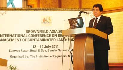
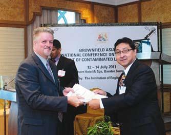
by Ir. Santha Kumaran a/l Enusan Krishnan, Organising Chairman, Brownfield Asia 2011
Our Earth is not getting any bigger but our population is. Maximising the use of every piece of land on this Earth is imperative. This excludes the hills, forests and other plantations, which are not an option for any sort of urban development. We need to preserve green fields not only to avoid global warming, but also for us to reside on. We need to maximise the use of brownfield sites to reduce dependence on green fields. The U.S. Environmental Protection Agency (EPA) has defined the term “brownfield” as:
“….real property, the expansion, redevelopment, or reuse of which may be complicated by the presence or potential presence of a hazardous substance, pollutant, or contaminant.”
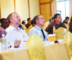
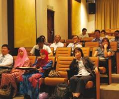
The Environmental Engineering Technical Division of IEM successfully conducted the 5th Brownfield International Conference from 12 to 15 July 2011. A total of 120 local as well as foreign participants took part in the event. The conference included a technical site visit to the Petronas Oil Refinery Plant in Melaka, which was an opportunity to experience the real development of brownfield land. A post-conference workshop on the “Application of Contaminated Land and Management Guidelines” was held on the final day.
Y.B. Tan Sri Datuk Seri Panglima Joseph Kurup, the Deputy Minister of the Ministry of Natural Resources and Environment, officiated the event while IEM President Ir. Vincent Chen Kim Keong delivered the welcoming speech.
Various international and local papers were presented. Although it would be impossible to highlight all the presented papers here, there were several inspiring and resourceful papers. Here are some of the papers that were presented:
• Datin Hajjah Hanili bt Ghazali from the Department of Environment (DOE) - Guidelines for Contaminated Land Management and Control in Malaysia
• Dr Kylie Dodd from the Environmental Resource Management (ERM) - Australian National Guidance on Health Risk Assessment and Health-Based Investigation Levels for Soils
• Dr Randy H. Adams from Villahermosa, Tabasco, México - Revitalisation of the Agua de Mina Waste Dam for Aquaculture
• Mr. Ng Hong Seng from AECOM - Latest Development on Remediation Technology for Brownfield Development
While there were many knowledgeable professionals on brownfield, the introduction of various technologies and innovations caught the attention of the participants. This contributed to the success of the 5th edition of the Brownfield Conference where a whole lot of business opportunities were simply waiting to be explored and seized. n
a Look at Brownfield Management Issues in Southeast Asia
In the mind of the public, environmental engineering has often been associated with wastewater management, as well as water and air pollution. However, that changed in 2001 when the first Brownfield Conference was organised in order to identify some of the significant issues associated with brownfield management.
Since then, there have been some significant improvements in terms of the introduction of brownfield management policies and guidelines. JURUTERA sought the opinions of Prof. Sr. Ir. Dr Suhaimi Abdul Talib, Assistant Vice Chancellor from Universiti Teknologi MARA, Puncak Alam campus, and Ir. Dr G. Balamurugan, Managing Director of ERE Consulting Group, on this matter.
Ir. Dr Balamurugan stated that one of the major concerns regarding brownfield management revolves around the presence of many unidentified or forgotten contaminated sites throughout the country. However, he believed that this problem is not unique to Malaysia as many former waste dump and industrial sites throughout the Southeast Asia region have been developed without any remedial action.
In Malaysia, Prof. Sr. Ir. Dr Suhaimi pointed out that some of these issues remain unresolved due to low awareness by the general public, service providers, consultants and regulators, which has resulted in a lack of specific legislation on contaminated land.
In recent years, the Department of Environment (DOE) has taken several initiatives to resolve the problem. The latest initiative involved the introduction of three new guidelines at the recently held Brownfield Conference, namely, the Guidelines for Assessing and Reporting Contaminated Sites, Guidelines for the Remediation of Contaminated Sites and Guidelines for the Planning and Management of Contaminated Land. Although at present these guidelines are voluntary in nature, they will be made mandatory in the next few years.
Assistant Vice Chancellor from Universiti Teknologi MARA
Prof. Sr. Ir. Dr Suhaimi Abdul Talib
According to Prof. Sr. Ir. Dr Suhaimi, SIRIM has also introduced a site remediation guideline entitled, “Developing and Implementing Early Action Guidelines for Site Remediation”, which is the first Malaysian Standard (MS2072:2008) that aims to provide guidance for assisting in the development, selection, design and implementation of partial, short-term or early action remedies undertaken at sites of waste contamination for the purpose of managing, controlling or reducing risk posed by environmental site contamination.
He noted that the National Urbanisation Policy (NUP) 2006 which was formulated by the Federal Town and Country Planning Department includes key policies that are relevant to soil remediation (Hashim, 2006). He said, “Policy Number 6 of the NUP calls for urban development as a priority for development strategies in urban areas which includes the implementation of infill development in potential areas; identification and registration of contaminated land; rehabilitation of contaminated sites prior to being developed; and the promotion of the private sector’s involvement in urban redevelopment by provision of incentives and joint ventures with government agencies.”
However, despite the introduction of these guidelines, Ir. Dr G. Balamurugan pointed out that brownfield management has not yet become a priority in Malaysia. He said, “We do not have specific laws to deal with brownfields. The priority right now would be to develop an inventory of brownfield sites in the country.”
Prof. Sr. Ir. Dr Suhaimi concurs, adding that, “To date, the country has yet to establish a National Register of Contaminated Land which should include a classification of contaminated land based on the contaminant. This should be introduced as soon as possible if we are to address brownfield management issues effectively.”
The lack of urgency in addressing these issues could stem from the fact that many are unaware of the consequences. Prof. Sr. Ir. Dr Suhaimi stated that development on contaminated land will expose the public to long term health risks. In addition, such development can lead to the devaluation of the property value in the area as well as accelerate the use of remaining greenfields.
Take, for example, certain areas within Shah Alam where there is a mix of industrial, commercial and residential development. The lack of legislation means that industrial businesses in the area cannot be taken to task if their land was found to be contaminated. The effect can be disastrous as developers may unwittingly develop the contaminated land for residential development once these businesses cease to operate.
Ir. Dr G. Balamurugan pointed out that, “Taking remedial action after a structure or facility has been built on top of contaminated sites will be very expensive. There is no doubt that the health impact on people living at these sites will be significant although this will be difficult to detect in the short term.”
As such, Prof. Sr. Ir. Dr Suhaimi hoped that the guidelines by the DOE will become regulation by the middle of the 10th Malaysia Plan. This, he believed, will lead to two major developments. Firstly, it could lead to capacity building for local
engineers who specialise in the area of brownfield management. Secondly, a landowner or occupier will be made liable if contaminants are found on their land.
He stated that, in general, the effort to deal with the brownfield management issue is an ongoing process. Although there has been much improvement compared to the situation 10 years ago, he believes that much more could be done.
For example, he pointed out that the NUP 2005 serves as the policy that addresses this issue from the planning point of view. However, there is no specific policy on assessment, screening and technology. He suggested that a more effective enforcement of this policy would help improve the situation.
Efforts by other agencies include initiatives by SIRIM which is in the process of drafting several more standards related to this issue. Initiatives by the DOE included the Environmental Quality (Scheduled Wastes) Regulations 2005 (EQA (SW) R 2005), which came into force on 15 August 2005, followed by a significant landmark in 2006 where a section was created within the Hazardous Substances Division to look into the issue of contaminated lands. This section aims to provide more focus and better governance on scheduled waste classification, generation, transportation and treatment.
Prof. Sr. Ir. Dr Suhaimi believed that learned societies such as the Institution of Engineers, Malaysia, also has a role to play by promoting conferences, courses and workshops on brownfield management. He said, “This series of Brownfield Asia Conferences must be continued. The question of whether the conferences are generating income for the institution must take second place. The primary role of these conferences is to promote awareness and the change of practices through the development of regulatory instruments and R&D activities.”
The majority of brownfield management failure in the country as reported by the media is mainly due to ineffective enforcement by the authorities. According to Prof. Sr. Ir. Dr Suhaimi, in 2004, Ir. Lee Heng Keng, Deputy Director General (Operation) of the DOE, reported that the main source of contaminated land was attributed to the illegal dumping of scheduled wastes. The situation is considered critical as more than 10 cases of illegal dumping per year are being reported, often occurring in remote areas.
Lack of awareness and greed have been identified as some of the major factors for these illegal dumping activities. Further, it was also found that many industrial premises have yet to provide any assessment on soil contamination.
Part of brownfield management consists of the adoption of remediation technology to ensure that contaminated land can be redeveloped. Ir. Dr G. Balamurugan said, “There are hundreds of different technologies for brownfield remediation that have been developed throughout the world. What is important for Malaysia is to adopt a technology that is best suited for our local conditions and the nature of contamination.”
Prof. Sr. Ir. Dr Suhaimi has a slightly different point of view. He said, “I believe the country needs to develop techniques on screening and assessment, especially those related to vapour intrusion, before we focus on remediation technology. Remediation is an expensive business. It is important that the screening and assessment methods are refined so that we can deal with the right problems.”
He added that remediation technology is generally divided into ex situ and in situ treatment, with the latter gaining more support in recent times. Bioremediation is also emerging as a potentially economical option for brownfield remediation, while the use of nano and bio technology for brownfield remediation has also developed quite rapidly. One of the latest technologies involves sustainable remediation, which not only focuses on the effectiveness of the method, but also the impact of the method on the environment.
According to Prof. Sr. Ir. Dr Suhaimi, in Berlin, Germany, certain areas of the city have yet to be redeveloped since being contaminated by the hazardous bombs of World War 2. Although the city council has issued contracts for the remediation of these areas, such efforts can take between five to ten years.
On whether there have been any successful case studies of brownfield development, Ir. Dr G. Balamurugan said, “Many former dump sites have been successfully rehabilitated in Malaysia. However, these are usually expensive ventures. As such, this is now a question of how much resources the government can allocate for the rehabilitation of brownfields in the country.”
Prof. Sr. Ir. Dr Suhaimi pointed out that some of the brownfield redevelopment sites that are being perceived to be successful include Sunway Lagoon and its surrounding areas, the Mines and KL Sentral. He said, “These projects were carried out by major players in the industry, as such these players have a reputation to maintain. The redevelopment of these projects would have been carried out in accordance to some in-house or foreign guidelines.” However, the question is, is post remediation monitoring being done for such projects? If so, are the results being made accessible to the public or, at the very least, the regulators? n
Steel Mill Deal for Hiap teck Subsidiary
Eastern Steel Sdn Bhd, Hiap Teck Ventures Bhd’s 55% owned subsidiary, has entered into an engineering and procurement contract worth RM417.83 million, and a construction contract worth RM232 million, with China Shougang International Trade and Engineering Corp for the design, procurement and construction of the first phase of an integrated steel mill in Teluk Kalung, Kemaman, Terengganu. The integrated steel mill will have an annual capacity of 0.7 million tonnes of steel while the completed integrated steel mill will have a total annual capacity of 3.5 million tonnes of steel. The project plant is expected to be completed by 2013. Hiap Teck will fund its 55% portion via a fund raising exercise involving a proposed right issue with warrants and the proposed issuance of convertible bonds. Hiap Teck will also issue 32.2 milllion of Hiap Teck shares to China Shougang or its nominated affiliates as placement shares at an issue price to be agreed upon as a condition to the engineering procurement contract and the construction contract.
(Sourced from The Star)
rM6 Billion West Coast Highway Project to Start in December
The construction of the 286km-long West Coast Highway linking Banting in Selangor and Changkat Jering in Perak will begin by December. The Works Ministry was in the final stages of completing the highway alignment works. The highway, which was estimated to cost around RM6 billion, would enhance connectivity and cut travelling time between towns located along the stretch. The West Coast Highway project was one of the six Public-Private Partnership initiatives to be carried out under the 10th Malaysia Plan on a build-operatetransfer basis.
(Sourced from BERNAMA)
China Shows Interest in Klang river rehabilitation Project
China has shown interest in participating in the RM10 billion Klang River rehabilitation project. A delegation from China State Construction Engineering Corp (CSCEC), the largest construction company and the largest international general contractor in China, was scheduled to make a visit to Malaysia to conduct a survey and feasibility study on the project. The Selangor Government, in its economic stimulus package, has identified six major areas to spur economic growth, namely, cleaning and rehabilitating the Klang River; expanding the transportation system; upgrading and replacing water assets; urban renewal programme; reviving abandoned housing projects; and increasing paddy yield.
(Sourced from BERNAMA)
SeB to Consider rerouting transmission Line for SCOre to Build another Dam
Sarawak Energy Bhd (SEB) is studying a plan to reroute a 275kV transmission line, currently being built to channel electricity generated by the RM3 billion Murum hydro dam to the Sarawak Corridor of Renewable Energy (SCORE), to facilitate the construction of another dam in Balepeh. The latter, located in the upper reaches of the Balui River where the 944MW Murum dam is being built, can generate 110MW. The RM100 million transmission line, originally scheduled for completion in the third quarter of 2012 – a year ahead of the first power to be commercially produced by the Murum dam, would connect the latter to the transmission system near Bakun.
The Murum dam project, which was 44% completed, is located about 60km upstream of the Bakun dam. SEB has also identified other hydro dam projects upstream of the Balui River, namely, Linau (290MW) and Danun (200MW). Undertaken by Three Gorges Development Corp (M) under a single contract with SEB, the Murum dam comprises several key components, namely, a 145m high roller-compacted concrete dam, intake and 2.7km long tunnels supplying water to a 944MW power house. The Murum dam is a key part of the SCORE project and would be the next major hydro generation project to be commissioned after the Bakun dam. Murum electricity power is slated to come in time to take up the power demand from SCORE industries which the Bakun dam is unable to meet.
(Sourced from BERNAMA)
additional 20MW of electricity Generating Capacity for Sabah
The signing of a renewable electricity purchase agreement (REPA) between SESB Sdn Bhd and ECO Biomass Power Sdn Bhd has lead to an increase of another 20MW for Sabah's electricity generating capacity. The RM164.9 million project by ECO Biomass was expected to start operations by end of 2012. Under the REPA, Eco Biomass would supply electricity generated using oil palm empty fruit bunches to SESB for 21 years. It was the fourth biomass project in Sabah after TSH Power in Tawau, and Seguntor Power and Kinabio Power in Sandakan whose generating capacity was 10MW each. Since 2002, SESB had signed five REPAs with independent power producers and was in discussion with 10 more companies on the development of renewable energy-based power stations such as biomass, biogas, hydro and geothermal. To date, three companies that use biomass and one that operates a hydroelectric station has supplied 32MW to the Sabah Grid System, which represented 2.8% of the state's generating capacity and only 0.5% of the national capacity.
(Sourced from BERNAMA)
What You Need to Know about Bitumen rheology
this paper intends to compile a number of fundamental descriptions concerning the science of bitumen rheology. Understanding bitumen rheology is a major concern since the mechanical properties of binders are closely linked to the service behaviour of actual flexible pavements.
Rheology involves the study and evaluation of the flow and permanent deformation of time-temperature dependent materials, such as bitumen, that are stressed (usually shear stress or extensional stress) through the application of force. The word rheology is believed to originate from the Greek words " ρεω ", which can be translated as "the river, flowing, streaming", and " λογοο " meaning "word, science" and, therefore, literally means "the study of the flow" or "flow science" [1].
In the Rheology Bulletin, Morrison [2] translated the word rheology as, "Rheology is the study of the flow of materials that behave in an interesting or unusual manner. Oil and water flow in familiar, normal ways, whereas mayonnaise, peanut butter, chocolate, bread dough, and silly putty flow in complex and unusual ways. In rheology, we study the flow of unusual materials". The rheology of bitumen can be defined as the fundamental measurements associated with the flow and deformation characteristics of bitumen.
Therefore, understanding the flow and deformation (rheological properties) of bitumen in an asphalt mixture is crucial for pavement performance. Asphalt mixtures that deforms and flows too readily may be susceptible to rutting and bleeding, while those that are too stiff may be exposed to fatigue and cracking.
The study of bitumen rheology is not a new field and has been extensively studied all over the world. It is so well established that the most famous rheology tests on bitumen was started in 1927 at the University of Queensland in Brisbane, Australia (Figure 1). Professor Thomas Parnell initiated "the pitch drop" experiment, a test that consists of a bituminous-like pitch, slowly dripping out of a funnel at room temperature.
This test is considered as the longest rheology experiment and, up to the present time, only eight drops have fallen. The pitch has an estimated viscosity of approximately 230MPa.s [3]. Considerable efforts have been undertaken by bitumen and paving technologists over the last five decades to study the rheological properties of bitumen [4]. Nevertheless, the study of bitumen rheology is not widespread in Malaysia.
The rheological properties of bitumen are measured using conventional tests including softening point, viscosity (at 65oC and 135 oC), elastic recovery (at 25 oC by using a ductilometer), storage stability (penetration point, softening point), flash point and tests after thin film oven ageing (softening point, viscosity, elastic recovery). However, these measurements are insufficient to properly describe the rheology and failure properties that are needed to relate bitumen properties to asphalt mixture performance. The reliability of the tests is also often questionable. In addition, these tests do not quantify the time-dependent response of the binder and are not suitable to measure the rheological properties of modified binders.
Nowadays, the rheological properties of bitumen are usually determined using an oscillatory type testing apparatus known as a dynamic shear rheometer (DSR). This method was initially introduced during the Strategic Highway Research Program (SHRP) in 1993. The DSR is a very powerful tool used to determine the elastic, viscoelastic and viscous properties of bitumen over a wide range of temperatures and frequencies, often using the testing configuration shown in Figure 2.
Normally, the rheological properties of bitumens are presented in terms of complex modulus (stiffness) and phase angle (viscoelastic) master curves. Other equipment such as a bending beam rheometer (BBR) and a direct tension test (DTT) are used to measure the rheological properties of bitumen at very low temperature. However, these tests are not particularly relevant in our country's climatic condition. The rheological data of bitumens is presented in the following forms.
• Isochronal Plot: An equation or a curve on a graph representing the behaviour of the system at a constant frequency (time of loading). For example, curves of complex modulus as a function of temperature at constant frequency are isochrones [6].
• Isothermal Plot: An equation of a curve on a graph representing the behaviour of a system at a constant temperature. For example, curves of complex modulus as a function of frequency at constant temperature are isotherms [6].
• Black Diagram: A graph of complex moduli versus phase angles. The frequencies and temperatures are eliminated from the plot, which allows all the dynamic data to be presented in one plot without the need
by En. Nur Izzi bin Md. Yusoff, Assoc. Prof. Dr Mohd Rosli bin Hainin and Prof. Gordon D. Airey
to perform the time-temperature superposition principle (TTSP) manipulations on the raw dynamic shear data [1].
• Cole-Cole Diagram: A graph of loss moduli as a function of storage moduli. This plot provides a means of presenting the viscoelastic balance of the bitumen without incorporating frequencies and/or temperatures as one of the axes [1].
• Master Curves: It is found that there is a relationship between temperatures and frequencies (times of loading) which, through timetemperature shifts, can incorporate measurements done at different temperatures to fit into one overall continuous curve at a reduced frequency. The curve, known as a master curve, represents the binder behaviour at a given temperature over a wide range of frequencies [1].
Recognising that testing is generally laborious, time consuming and expensive, and require skilled operators, rheological models can be taken as a valuable alternative tool to quantify the rheological properties of bitumens [7]. In general, all the models are able to satisfactorily predict the rheological properties of bitumen in the linear viscoelastic (LVE) region.
In the 1950s and 1960s, nomographs were used to represent the rheological properties of bitumen. However, nomographs become obsolete with time due to the invention of computational techniques and were replaced by mathematical and mechanical element approaches. The advantage of the latter is that elements might be relatable to structural features. Figure 3 shows an example of the complex modulus and phase angle master curves predicted by means of the rheological model.
As mentioned before, the DSR rheological data of bitumen is obtained in the frequency domain. According to the theory of viscoelasticity, by using specific mathematical inter-relationship equations, one LVE function can be converted into another LVE function even though they emphasise different information [8]. For instance, the rheological data in the frequency domain can be converted into other functions in the time domain.
The use of data interconversion equations is really useful compared to conducting several tests simultaneously. Many computer programs, such as the Interactive Rheological Software (IRIS), the Non-linear Regularization (NLREG) and the Rheology Analysis (RHEA) are
commercially available. The RHEA, for example, is available to simplify the process involved in the construction of master curves.
The rheological properties of bitumen can normally be improved with the addition of modifiers such as fillers, extenders, polymers (natural and synthetic), fibres, oxidants and anti-oxidants, anti-stripping agents and hydro-carbons. For example, the use of polymer modified bitumens (PMBs) helps improve its rheological properties over a wide range of temperatures and times of loading. The stiffness modulus and elasticity values of PMBs are significantly increased. They are more resistant to rutting, abrasion, cracking, fatigue, stripping, bleeding and ageing at high temperatures and brittle fracture at low temperatures.
There are many reasons why the smoothness of rheological data is disrupted. For example, the presence of highly crystalline bitumens, structured bitumen with high asphaltenes content, high wax content and highly modified bitumens can result in inconsistencies in the rheological properties of binders. This material is termed thermorheologically complex [9].
In summary, the rheological property of bitumen is an important parameter and reflects the actual flexible pavement performance. It is, therefore, recommended that this study be included as part of our paving standards as this exercise is widely practised among developed countries. n
refereNces:
[1] G.D. Airey. “Rheological Characteristics of Polymer Modified and Aged Bitumens.” PhD Thesis, University of Nottingham, UK, 1997.
[3] D. Lesueur. “The Colloidal Structure of Bitumen: Consequences on the Rheology and on the Mechanisms of Bitumen Modification.” Advances in Colloid and Interface Science, vol. 145, pp. 42–82, 2009.
[4] J.L. Goodrich. “Asphalt and Polymer Modified Asphalt Properties Related to the Performance of Asphalt Concrete Mixes.” Journal of the Association of Asphalt Paving Technologists, vol. 57, pp. 116–175, 1988.
[5] Pitch Drop Experiment. http://en.wikipedia.org/wiki/Pitch_ drop_experiment (Dec. 20, 2010).
[6] Eurobitume. “First European Workshop on the Rheology of Bituminous Binders”. European Bitumen Association, Brussel, 1995.
[7] J.D. Ferry. Viscoelastic Properties of Polymers. 2nd Edition. John Willey & Sons: New York, 1980.
[8] J.D. Plazek and I. Echeverria. “Don't Cry for Me Charlie Brown, or Compliance Comes Comprehension.” Journal of Rheology, vol. 44, pp. 831–841, 2000.
[9] G.D. Airey. “Use of Black Diagrams to Indentify Inconsistencies in Rheological Data.” Road Materials and Pavement Design, vol. 3, pp. 403–424, 2002.
travel BooK for sale
A travel book by Ir. Chin Mee Poon, in Mandarin, entitled “europe and
The 494-page book is now available at rM48.00 per copy, and can be purchased through the IEM office at 03-7968 4001/2, or email to pub@iem.org.my. Payment can be made by cheque to “The Institution of Engineers, Malaysia”. Part of the proceeds of every book purchased from the IEM will be channelled to the IEM Building Fund.
add delivery and handling costs of RM12.00* for Peninsular Malaysia and RM22.00* for Sabah and Sarawak. (*Note: Cost is subject to destination rate by Pos Malaysia)
Value engineering Workshop on a Major Industrial Project In Southern thailand
PrOJeCt BaCKGrOuND
by Ir. Jiunn S.Tan
The HTY project [1] is an industrial factory plant located in the Southern Region Industrial Estate (SRIE) on an approximate plot size of 210,335m2 in Songkhla province, Thailand. The new industrial factory plant is composed of three major building categories: ISBL (Production Activity Buildings), OSBL (General Activities Buildings), and Others (Raw water treatment station, waster water treatment plant and gas washing tower station).
ISBL Buildings Cluster is composed of Building No. 480-Latex Unloading Area, Building No. 481-Latex Tanks Area, Building No. 482-Slurry Building, Building No. 483-Process Building, Building No. 484-Carbon Black Storage Building and Building No. 485-Finished Product Warehouse. All buildings are architecturally composed together in the most effective juxtaposition and consecutive configurative layout format, with the proper selection of construction materials and systems to best suite and satisfy the most logistical flow of the plant operation process, function and design enhancements of natural lighting and ventilation, and optimal construction costs and time.
The central spine of the building cluster lays the key industrial plant operation process, which are the Outdoors Latex Unloading Area (starting off at the furthest eastern corner of the overall ISBL buildings complex) in direct physical adjacency with the Latex Area, then the four storey Slurry Building, Carbon Black Storage Building, three storey Process Building, then through the external Forklift Movement Area transporting the finished product to the Finished Product Warehouse for proper storage at the end of the process. The supporting facilities located around the peripheral with a direct link and accessibility to the main factory ISBL operation process spine are the following OSBL Buildings, namely, Building No. 150-Chemical & Physical Lab, Building No. 491-Offices & Lockers, Building No. 490-Electrical Substation 1 and BL-21-Main Electrical Building.
PurPOSe
The purpose of this workshop [2] is to describe the value engineering (VE) system for the HTY project. The primary objective of the system is to facilitate cross-functional learning, assist in adding value to the HTY project, avoid unnecessary expenditure, and provide a systematic, function based approach to improve the overall project execution while optimising costs without sacrificing safety or quality.
DeFINItION OF VaLue eNGINeerING (Ve) aND BaCKGrOuND VE is a creative and organised effort which analyses the requirements of a project for the purpose of achieving essential functions at the lowest total costs over the life of the project.
20 Fire Specification Replace CS by GRP for fire water network
290 Building Specification Sprinkler System Pump House - 127: Steel structure bldg on pad foundation (no piling), tank foundations on inverted T-pad footing (no piling).
1) Contractor confirmed there is no specific requirement by Thai regulations related to FW piping material.
2) Contractor to prepare MTO for U/G HDPE piping.
3) Evaluate construction constraints (Jan.11th Rev.)
1) Employer confirmed that this modification is acceptable and that the contractor shall proceed/implement this modification. (Jan.10th Rev.)
295 Building Specification Latex Unloading Area - 480: RC slab on grade 250mm thick (no piling). 1) Employer confirmed that the contractor shall proceed and implement this modification. (Contractor to verify and confirm if piles are not required due to diff settlement). (Jan 10th Rev.)
298 Building Specification ISBL buildings 482 and 483 columns to be in concrete instead of steel
300 Building Specification Calculate civil quantities saving if 3t/m2 is taken instead of 10t/m2 design criteria for Bldg 135
1) Building Construction S/C should still confirm if there is any impact.
2) If there is no schedule impact or if there is sch. saving, employer agrees to implement this item.
3) If there is schedule impact, contractor to come back to employer. (Jan.10th Rev.)
1) Employer confirmed that only one truck will be on Bldg 135 slab at the same time. Since Bldg 480 slab design criteria is 3t/m2 , employer and contractor agree that this 3t/m2 criteria can be used for Bldg 135 design. Contractor to proceed accordingly. (Employer to confirm this value when trucks characteristics are known) (Jan.10th Rev.)
111 Process Technology change Replace SS316L by CS for DWE WW tank piping and use pulled bends for the DWE WW piping
Process Technology change Manual valves on water circuit do not need to be ball valves (water and air circuits).
174 Process Technology change Eliminate carbon monoxide sensors on the DWE vent
1) P&ID marked up
2) Prepare associated MTO (piping) (Jan.12 Rev)
1) Mark-up P&ID were prepared
2) Prepare associated MTO (piping) (Jan.11th)
1) LIC confirmed that the sensors and associated analysers can be eliminated. LIC shall provide relevant documents to employer for their review and decision.
2) It will take some time before EMP can confirm its implementation.
3) Prepare corresponding markup P&ID's and associated MTO (Instrumentation). (Jan. 12th).
238 Electrical Specification Reduce Building 490 from two floors to one by locating the secondary transformers outside
1) Contractor confirmed outdoor oil type transformers are cheaper than dry type.
2) Employer and contractor agree that this lever should be studied (Roof above transformer, fire walls are required) in conjunction with lever 188. Corresponding MTO (civil, electrical) of the optimum solution to be developed. (Jan.12th)
Contractor proposes an alternative to have Bldg 127 structure in reinforced concrete and to modify the foundation design without piling. Employer agreed on Jan.10th to implement this item. 5,670,000
Contractor initially designed Bldg 480 with piles but has revisited the design since then and can cancel these piles.
Employer agreed on Jan.10th to implement this item. 4,810,050
ISBL ITB documents calls for BL 482 and 483 structures to be in steel. Contractor proposes to have these buildings structure in reinforced concrete. In addition to the structural material, this will reduce significantly the fire proofing cost. Without cost impact on the schedule, employer agreed on Jan.10th to implement this item. 14,169,750
Contractor deems that this design criteria is leading to excessive concrete quantities but need employer to determine the adequate revised design criteria which depends on the plant operation philosophy such as the number of trucks at the same time in this building.Contractor provides here the potential cost saving if 5t/m2 was considered. 6,294,200
Contractor shows on P&ID mark up (VE#111-1) and on "EL VE#111-2 Equipment List" the piping and equipment concerned by this lever. 5,445,000
Contractor confirms that manual valves on the water and air circuits are changed from ball valve to gate valve. P&ID markups (VE#170-1 and VE#170-2) are attached for employers’ review. 11,132,000
Contractor hereby provides the P&ID markup (VE#174-1) for this lever.
18,891,000 Table 1
Contractor confirms that Building 490 can be reduced from two to one floor.
1) To reduce Building 490 to one floor level, all LV switchgears located in second floor will be moved to ground floor level and the secondary transformers will be moved outdoor to a transformer yard area.
2) All outdoor transformers will be changed from dry-type cast resin to oil type Furthermore, the transformers shall be kept under roof and separated by fire walls.
3) Revised electrical room dimensions (50mx13.5m) and transformer yard area dimensions (39mx5m) are preliminary estimations only.
4,950,000
Through a group investigation, using experienced, multi-disciplinary teams, value and economy are improved through the study of alternate design concepts, materials and methods without compromising the functional and value objective of the client. The Society of American Value Engineering (SAVE) was formed in 1959 as a professional society dedicated to the advancement of VE through a better understanding of the principles, methods and concepts involved. Now known as SAVE International, the latter has grown to consist of over 1,500 members and currently has over 350 active Certified Value Specialists (CVS) in the United States.
reaSONS FOr POOr VaLue
The following is a partial list of the reasons for poor values:
• Lack of and/or poor coordination among designers
• Failure to network with customer which leads to a poor definition of needs and wants
• Design based on habitual thinking or mistaken belief
• Insufficient time for project formulation and/or design
• Failure to utilise the latest technology
• Negative attitude
• Poor communication in developing project scope
• Lack of consensus among project stakeholders with regards to project scope
• Outdated or inappropriate design standards
• Incorrect assumptions based on poor information
• Fixation with previous design concepts
rOLeS aND reSPONSIBILItIeS [2]
Client and Client’s representative
The employer and its representatives for the HTY project are responsible for defining the VE exercise objectives, the criteria on which he wants the Value Improving Practice (VIP) to be evaluated, and which project constraints are fixed and which ones are variable.
Contractor
The contractor project manager of the HTY project is responsible for the implementation of the VE System, the management and the control of this workshop.
Ve Lead Facilitator
He is responsible for the content of this workshop. He defines the various steps of the overall VE exercise and defines the agenda and the participants of the various meetings and workshop. He familiarises all users with the VE Process.
Ve Data Base Manager
Controls access to the VE ideas stored in the database. Maintains the system, and maintains the integrity and confidentiality of the system and its content. He familiarises all users with the VE Process. The authorising manager may be, or can be designated by, the project manager.
Project or Discipline/Department Managers/Project technical Lead
Arrange for the collection and analysis of potential VE ideas in a systematic manner. Project managers are required to arrange this activity at an appropriate time with respect to the schedule during execution. Project managers shall determine the frequency of follow up meetings based on the specific project requirements and need. The project technical lead will normally be responsible for gathering the information needed for the workshop. Also, the project technical lead is generally expected to be the most knowledgeable on the cost estimate content and basis. This is important when determining if an idea represents savings, or is already the basis of the estimated cost. For the execution of the BED works, the estimating project lead will have significant input when there is a need for the order of magnitude estimates to quantify ideas.
Subject Matter experts
Assists in the analysis of VE ideas when they are collected if required; evaluate the potential VE residing in the database and determine whether it is to be stored or rejected; validate a VE idea periodically.
eXaMPLe OF Ve WOrKSHOP
Table 1 shows the partial list of selected levers approved by the client for implementation with significant savings and negligible schedule impact.
CONCLuSION
In the final analysis, VE is not only beneficial, but essential because:
• The functionality of the project is often improved and produces tremendous savings, both for the initial and lifecycle cost.
• A “second look” at the design produced by the architect and engineers gives the assurance that all reasonable alternatives have been explored.
• Cost estimates and scope statements are checked thoroughly to ensure that nothing has been omitted or underestimated.
• Assures that the best value will be obtained over the life of the project. n
Note:
The author is a practising professional engineer with a major international contractor/consultant company in the oil and gas industry and currently posted in Bangkok.
reFereNCeS:
[1] Technip, Technical Proposal for HYT Project by Pierre E Crouzier, March 2011
[2] Technip, Value Engineering Procedure for HTY Project by Robert Clark, March 2011
the Myths of Premature Failure of Plastic Pipes in Plumbing applications
by Ir. A. H. Ung
Plastic pipes, or more accurately, thermoplastic pipes, have been in use in plumbing applications since the late 1970s. Over the years, it has gained more acceptance and, invariably, its usage has increased as it has certain distinct advantages over existing material such as GI pipe which was the material of choice in the old days. One of the distinct advantages of thermoplastic is that it does not corrode over time.
So what types of thermoplastic pipes are currently being used in the plumbing sector? There are currently several thermoplastics that are being used for plumbing applications. The most common are ABS, HDPE, PVC and PPR.
Broadly speaking, thermoplastics can be sub-divided into two main categories, i.e. Amorphous and Crystalline. Examples of two common materials are ABS and HDPE, where the former is Amorphous and the latter is Crystalline. The main difference between the two is the method of jointing. Amorphous material uses bonding agents such as ABS Solvent Cement, while Crystalline uses heat such as HDPE Butt/Electro Fusion.
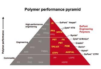
Apart from the above classifications, thermoplastics are further classified into Commodity, Engineering and High Performance plastics. From the DuPont Polymer Performance Pyramid as shown in Figure 1, PVC, HDPE, PP (PPR, PPH) are Commodity Plastics, while ABS and PET are classified as Engineering Plastics. Thus, PVC, HDPE and PPR pipes are cheaper than ABS because of the difference in performances.
It is no secret that there are many incidences of premature failure of thermoplastic pipes in plumbing applications in many buildings, both residential and commercial high-rise buildings, that use thermoplastic as the plumbing material. Often, the comments are that the thermoplastic pipes cannot withstand the pressure, especially so when it is used as the pumping mains. So, is this comment the gospel truth or a myth?
the Myths
For lack of a better term, the comment on the premature failures shall be termed as myths. This is an attempt to list down, although the list may not be exhaustive, the most common myths, which are:
1) Plastic pipes are not durable
2) Plastic pipes cannot withstand pressure and thus cannot be used as pumping mains
3) Plastic pipes are not suitable for outdoor installation
Plastic pipes are not durable
One of the most common comments is that the plastic pipes installed failed prematurely and sometimes even during the Defects Liability Period. Where did these failures occur?
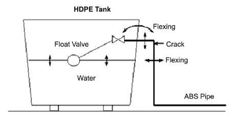
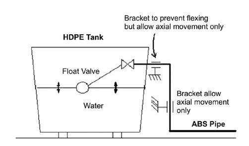
In landed residential properties, the most common failure occurs at the inlet pipe to the HDPE water tank. Normally, the symptom is the shearing of the elbow at the inlet area. Of course, the first reaction is that the material is brittle. Upon closer investigation, one will invariably discover that there is flexing of the HDPE tank and the flexing forces are transferred to the inlet pipe which was not properly bracketed to prevent the shearing of the pipe. Figures 2 and 3 depict the flexing of the HDPE tank and the brackets required to prevent the shearing of the pipe. In some cases, the installer will claim that his installation has the
(Source: http://www.azeetapipe.com)
Figure 1: The DuPont polymer performance pyramid
Figure 2: Common failure at inlet to HDPE tank
(Source:http://www.azeetapipe.com)
(Source:http://www.azeetapipe.com)
(Source:http://www.azeetapipe.com)
necessary bracketing and yet the pipe still failed. Although there is some element of truth in that statement, one should determine if the brackets were installed properly in the first place? Let us take a look at Figures 4 and 5.
Admittedly, the pipe may sometimes be brittle as a result of the non standard manufacturing process. This normally happens when unscrupulous manufacturers use adulterated material to manufacture plastic pipes. They may use recycled material and/or calcium carbonate added as filler to reduce the manufacturing costs (the addition of calcium carbonate as filler only applies to PVC products).
Consequently, the pipes will not have the same mechanical properties as the virgin or unadulterated
material. Such an unethical practice is quite rampant especially among the PVC, HDPE, PPR and ABS manufacturers. Apart from being unscrupulous, some manufacturers also lack the technical knowledge to produce good quality plastic pipes.
Plastic pipes cannot withstand pressure and thus cannot be used as pumping mains
The general belief is that plastic pipes are unable to withstand pressure, as such, they cannot be used as pumping mains. This myth is indeed the most intriguing as all applications, whether the pumping or gravity feed is pressurised. The question one should ask is, “how can the same plastic pipe, that supposedly cannot be used for pumping, withstand the static pressure of the rooftop tank or the incoming pressure from JBA?” Sometimes, the static pressure can even exceed the discharge head of a domestic pump installed in the same building.
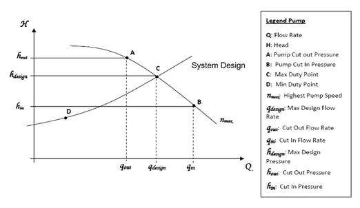
The myth came about due to the mismatch of the pumping equipment with the design criteria. To understand the mismatch, one needs to look at the pumping system installed in the building. Firstly, the engineer will design the Total Water Requirements of the building which, invariably, will be listed as x flow rate against y head. The installer will then request from the pump supplier for a pumpset which will deliver the designed duty point. Therein lies the mismatch as, more often than not, there is no pumpset that will deliver exactly the desired duty point, although this is not the main issue. The problem may also lie in the pump’s performance during the actual operation which does not match with the engineer’s design.
In Figure 6, the pump will operate between points A and B according to the performance curve whereas the system requirements are between points C and D. Clearly, there is a mismatch especially when the demand is at point D and the pump is operating at point B. In this situation, the velocity will be very high, and can sometimes be as high as 5ms-1 to 6ms-1, and will create a transient pressure that is much higher than the rated working pressure of the plastic pipe. There are cases where the transient pressure created is as high as 30 bars. Obviously, plastic pipes with a rated working pressure below that level will fail prematurely
(Source:http://www.azeetapipe.com)
Figure 3: Recommended pipe bracket installation
Figure 6: Single speed operation
Figure 4: No proper bracketing
Figure 5: Thin wire used as pipe bracket
(Source:http://www.azeetapipe.com)
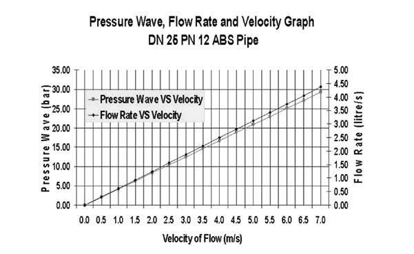
(Figure 7 gives an example of the velocity of flow vs transient pressure or pressure wave created in an ABS pipe).
To make matters worse, due to the lack of understanding and knowledge on transient pressure, the installer will think that the plastic pipes are unable to withstand the pump discharge pressure and will attempt to mitigate the situation by lowering the cut in pressure. This seemingly helpful remedial action will, in actual fact, create a higher transient pressure as the increase in volumetric flow rate without the corresponding increase in pipe diameter will escalate the transient pressure created. As such, the plastic pipes will experience more frequent failures and that will lead the installer to believe that the plastic pipes are truly useless as they fail even more frequently despite the lower pump discharge pressure.
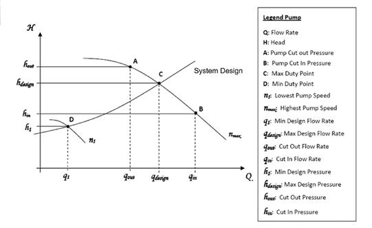
The correct remedial action will be to match the pump operation to the design requirements all the way as shown in Figure 8. This can be achieved with the use of a variable speed pump with the lowest and highest speed, n1 and n max, calibrated to match duty points D and C respectively. This will ensure that whatever transient pressure created will be lower than the rated working pressure of the plastic pipes.
A similar failure arising from the transient pressure can also occur in the dropper especially when there is insufficient or inappropriately sized PRV installed. In addition, bad PRV installation, as shown in Figure 9, where the PRV installed is without pressure gauges can also create havoc in the system. It is common knowledge that a proper PRV installation maintains
Provide Steam Solution For tomorrow’S induStry energy needS
We specialize in the design, manufacture and supply of….
• Biomass Boiler
• Heat Recovery Steam Generator (HRSG)
• Oil/Gas Fired Packaged Boiler with auxiliary equipment to enhance boiler performance and efficiency
• Grate : Vibrating, Reciprocating
• Boiler Feedwater Economiser
• Air Preheater
Figure 7: An example of the velocity of flow vs transient pressure or pressure wave created in an ABS pipe. (Source:http://www.azeetapipe.com)
Figure 8: Variable Speed Operation
constant downstream pressure, which is lower than the upstream pressure. So how can one set the pressure if a PRV is installed without pressure gauges?
It is also important to note that a PRV must have the feature to cater for small usage, without which the PRV will start hunting when the situation arises. During this operating condition, the velocity of flow through the PRV can be as high as 14ms-1 (see Figure 10). Under this condition, the transient pressure created can be very high which, again, will lead to the premature failure of the plastic pipes.
The other option is to install a series of smaller PRVs against a single big PRV in the dropper. Of course, the smallest PRV can cater for the small usage and the bigger units will cut in during higher demands. This arrangement will reduce the velocity of flow in the system which, in turn, will reduce the transient pressure to a more manageable level.
Plastic pipes are not suitable for outdoor installation
The general understanding is that plastic pipes are not suitable for outdoor installation as the pipes will become brittle. The fact is, all plastics are susceptible to UV attack. This includes water tanks, pipes and valves that are made from plastic. Regardless of the claims from some manufacturers that they have added a UV inhibitor into their products, all exposed installation of plastic products will meet their untimely demise if they are not properly protected. This is because the UV inhibitor that is added to the products is always finite and sacrificial in nature. So once the added UV inhibitor is fully consumed, the material will be attacked by UV and, over time, the plastic products will degrade and fail prematurely.
Therefore, it is always a wise practice to protect the plastic products by coating them with a layer of water-based paint. This paint will shield the product and thus prevent the material from being attacked and degraded by UV.
The other aspect is the thermal expansion or contraction, particularly for exposed plastic pipe installed over a long distance. Most are unaware that plastics, in general, expands and contracts more than steel. In addition, dark coloured plastic pipes such as HDPE and ABS will yield a higher surface temperature during a hot sunny afternoon. From experience, the measured surface temperature of exposed ABS pipe installed on a rooftop can reach a high of 600C. At night, it can fall to 200C. The wide delta T will result in the expansion/contraction of the pipeline and, if this is not taken care of, will invariably cause a
Figure 10: PRV installed without pressure gauges (Source:http://www.azeetapipe.com)
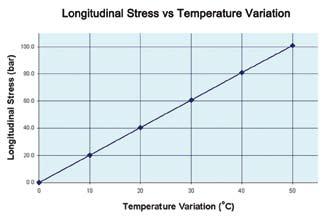
premature failure of the plastic pipeline. Figure 11 shows the relationship between the longitudinal stress of the ABS pipe against temperature.
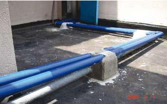
More often than not, the installer will install the exposed and unprotected plastic pipes, and secure it firmly with cement mortar (Figure 12). Such installation will definitely
kill the pipeline as there is no allocation for the pipeline to move in a pre-engineered manner.
Plastic pipe manufacturers will be able to provide the coefficient expansion of their respective materials and a simple calculation will yield the necessary expansion/ contraction that needs to be allocated in the pipeline with a suitably chosen anchor point.
suMMary and conclusion
In view of the explanation, it is clear that the premature failure of plastic pipes is not due to their inherent material weaknesses, but instead is caused by poor installation, lack of understanding of the characteristics of the plastic materials and the mismatch of pumping equipment.
Although plastic pipes have some distinct advantages over steel pipes, they also have their weaknesses. Their main weakness is the lower Modulus of Elasticity as compared to steel which renders them unable to withstand the high transient pressure created in the system.
Nevertheless, this weakness can be easily overcome by proper engineering to avoid excessive transient pressure in the system so that the plastic pipeline will not fail prematurely.
Of course, it is also important to identify unscrupulous manufacturers and avoid buying their products however cheap their products may be. On the other hand, the authority concerned can request for all plastic products to be produced in their natural resin colour of which any addition of colour will be considered as adulteration and thus will be rejected. This will help reduce or eliminate the opportunity for unscrupulous manufacturers to use recycled or adulterated materials.
In conclusion, it is possible to design and install a plastic piping system that can survive a design life of 50 years with the most optimal cost. In order to achieve that, we must equip ourselves with the appropriate technical knowledge and understanding of the characteristics of plastic materials.n
1Sudoku centerpiece "1"
by Mr. lim teck Guan
Fill in the remaining 80 squares with single digits 1-9 such that there is no repeat of the digit in every Row, Column and Block. The number at the top left hand corner of the dotted cage indicates the total for the digits that the cage encompasses.
For tips on solving, visit www.1sudoku.com.my Twin Tree Publishing (Solution is on page 42 of this issue.)
Figure 11: The relationship between the longitudinal stress of the ABS pipe against temperature (Source:http://www.azeetapipe.com)
Figure 12: Exposed ABS pipe secured firmly with cement mortar
Practical Strategies for addressing the Vapour Intrusion exposure Pathway
1. INtrODuCtION
The consideration of vapour intrusion risk as part of contaminated land site assessments is receiving increasing attention in Asia. Vapour intrusion assessments are a well established part of site assessments in the US, however, published guidance from the US EPA has not kept pace with actual practice, resulting in uncertainty for international users, who are also heavily reliant on this material.
Vapour intrusion assessments are frequently conducted using the Johnson and Ettinger model, which was recommended in the guidelines produced by the US EPA in the early to mid-2000s. Many sites will, however, fail this kind of vapour intrusion assessment because the vapour fluxes calculated from the soil or groundwater data tend to be overestimated. This is particularly the case for petroleum hydrocarbons because these types of traditional models do not account for the biodegradation of vapours in the presence of oxygen.
Recent developments in the methodology for the assessment of vapour intrusion have seen the adoption of more practical and site specific tiered vapour intrusion risk assessment approaches. This paper reviews some of the most useful guidance and assessment approaches.
2. VaPOur INtruSION
Vapour intrusion refers to the movement of volatile contaminants from soil or groundwater, via soil gas, into a building. If sufficient quantities of a contaminant vapour enter a building, and ventilation is insufficient to dilute the vapour, then the air quality inside the building can be affected. This can potentially lead to health and other risks to the building’s occupants.
The most common contaminants of concern for vapour intrusion are chlorinated solvents and petroleum hydrocarbons.
3. SCreeNING aSSeSSMeNt PrOCeSSeS
3.1 Conceptual Site Models
The first stage of a vapour intrusion risk assessment is to develop a CSM, which is the qualitative description of the plausible mechanisms (‘pathways’) by which people or sensitive environments (‘receptors’) may be exposed to site contamination (‘sources’).
The CSM should consider the susceptibility of the site to a vapour intrusion risk. Key criteria that influence the likelihood of a vapour intrusion risk include:
by Dr Kylie Dodd and Dr Sophie Wood
• The volatility and toxicity of the contaminant compounds;
• The contaminant depth below ground level;
• The proximity of the contamination to a current or future building; and
• Building construction details, including the presence of basements, surface cover and preferential pathways.
It is possible to produce a ‘no risk’ conclusion for vapour intrusion at the CSM stage of an investigation, thereby focusing the requirement for more detailed vapour intrusion investigations on the higher risk sites.
3.2 exclusion Distances
Recent studies have led to a number of bodies such as the Californian State Water Control Board and the American Society for Testing and Materials (ASTM) making recommendations around generic vapour intrusion exclusion distances for contaminated sites. An ‘exclusion distance’ is the distance (vertical or horizontal) between the soil or groundwater impact and the building structure, beyond which no vapour intrusion risk is likely. Published recommendations on exclusion distances are a useful tool in the first stage of a vapour intrusion risk assessment.
ASTM (2008) [1] recommends a vapour intrusion exclusion distance of 30m for non-biodegradable chemicals, excluding Non-Aqueous Phase Liquids (NAPL). This criterion can be applied across the range of volatile chemicals.
It is well known that there are many petroleum release sites worldwide, but relatively few documented cases of actual vapour intrusion problems associated with petroleum hydrocarbon vapours. A major reason for this is that petroleum vapours biodegrade rapidly in the presence of oxygen (CRC Care, 2009) [2].
The Californian State Water Control Board’s (2010) Leaking Underground Fuel Tank (LUFT) Manual provides alternate vapour intrusion exclusion distances specifically for petroleum hydrocarbon contamination, as summarised in Table 1. These exclusion distances account for the potential for petroleum hydrocarbon vapours to biodegrade.
The exclusion distance recommendations outlined in Table 1 were derived on the basis of the following data:
• Paired soil vapour and groundwater field data published by Davis (2006) [3], which reported complete attenuation of hydrocarbon vapours at petroleum release sites; and
High strength groundwater sources (Benzene > 1000µg/L and TPH > 10,000µg/L)
VaPOur INtruSION exCLuSION DIStaNCe (m)
1.5m or more of clean soil be-tween the bottom of the building and the shallowest impacted soil or impacted groundwater.
3m or more of clean soil between the bottom of the building and the shallowest impacted soil or impacted groundwater.
Measurable LNAPL 10m or more of clean soil be-tween the bottom of the building and the shallowest LNAPL source.
• Biodegradation modelling studies reported by API (2009) [4].
In the unsaturated zone, clean soil is defined as TPH concentrations less than 100mg/kg, PID readings of less than 10ppm, or oxygen present concentrations > 4%.
Under these conditions, it is assumed that natural attenuation is sufficient to mitigate concentrations of volatile petroleum constituents, given the exclusion distances listed in Table 1.
3.3 Chemical Characteristics
The US EPA’s current vapour intrusion guidance is a draft document dating from 2002 (US EPA 2002). It provides a framework for assessing whether a risk from vapour intrusion is likely to exist. Although this document is still in the drafting stage, and has become dated in many aspects, it is commonly used as the basis for vapour intrusion risk assessments internationally.
One of the most useful references in the document is a list of common chemicals showing volatility and toxicity, permitting the exclusion of sites where the chemicals of concern are either insufficiently volatile, or insufficiently toxic, to pose a risk from vapour intrusion, thereby negating the requirement for the consideration of vapour intrusion.
This document considers that a chemical is not sufficiently volatile to represent a vapour intrusion risk if its Henry’s Law constant is less than 1 x 10 -5 atm-m 3/mole.
4. VaPOur INtruSION MODeLLING
In the event that vapour intrusion cannot be ruled out in the CSM, a more detailed vapour intrusion risk evaluation may be required. One option for a second tier of vapour intrusion risk assessment is traditional vapour intrusion modelling. Recent scientific studies have also provided evidence to support the inclusion of biodegradation into traditional vapour intrusion models for petroleum hydrocarbons, using biodegradation factors or more advanced modelling approaches.
4.1 uS ePa approach
The US EPA’s (2004) [6] Users Guide for Evaluating Subsurface Vapour Intrusion into Buildings sets out a quantitative vapour intrusion assessment approach, based on the Johnson and Ettinger model. This approach forms the basis of the US EPA’s vapour intrusion spreadsheets and common proprietary risk assessment modelling software, such as BP RISC and the RBCA Toolkit.
It is important to recognise the limitations of the guidance, particularly for assessing vapour intrusion of petroleum hydrocarbons. The age of the guidance means that it was produced when the empirical data available for petroleum hydrocarbons were scarce, and therefore, it is based primarily on the understanding of the behaviour of chlorinated hydrocarbons and, to some extent, radon. The neglect of biodegradation effects in the US EPA’s modelling approach will often result in significant overestimation of risks from petroleum compounds.
It is noted that in 2009, the US EPA Office of Inspector General (OIG) carried out a review of the USEPA’s vapour intrusion guidance (US EPA, 2009) [7] and concluded that the current guidance was impeding efforts to manage vapour intrusion risk. This review recommended that the US EPA should update and finalise their vapour intrusion guidance, with specific recommendations to include guidance on the use of multiple lines of evidence to evaluate vapour risks and a specific approach for petroleum hydrocarbons.
Table 1: Vapour intrusion exclusion distances recommended in the LUFT manual for Petroleum Hydrocarbons
Indications are that the 2002 guidance will be finalised by November 2012 and a number of improvements and updates implemented.
4.2 The Significance of Biodegradation for Petroleum hydrocarbons
Petroleum hydrocarbon vapours biodegrade rapidly in the presence of oxygen. This means that a vapour intrusion risk modelled using the US EPA (2004) approach does not necessarily translate into an actual vapour intrusion risk, particularly for petroleum hydrocarbons. Biodegradation typically occurs much more slowly for vapours derived from chlorinated hydrocarbon contaminants and is, therefore, generally much less significant.
Petroleum hydrocarbon biodegradation occurs wherever sufficient oxygen is present, resulting in rapid reductions in hydrocarbon vapour concentrations over very short distances.
The Cooperative Research Centre for Contamination Assessment and Remediation of the Environment (CRC Care, 2009) [2] demonstrated that extensive building foundations can restrict oxygen penetration beneath the ground surface, leading to higher sub-slab vapour concentrations. Buildings with dimensions greater than 15m x 15m are noted in this publication as having the potential to limit subsurface biodegradation of petroleum hydrocarbon vapours. CRC Care (2009) [2] recommends the use of biodegradation adjustment factors of 10 and 100 for sources > 2m deep and > 4m deep respectively, in the absence of a large surface slab and when soil profile oxygen concentrations > 5% can be demonstrated.
The american Petroleum Institute (API) has also recently developed a vapour intrusion model which can accounts for the biodegradation of TPH vapours (API, 2010). This model is available publically and can be applied in site-specific quantitative risk assessments.
5. FIeLD VaPOur aSSeSSMeNt
A vapour investigation is an additional tier of assessment that can be undertaken to accurately assess the risks of vapour intrusion occurring at a site. The main benefit of site specific vapour investigations is that they have a high level of regulatory acceptance internationally, provide results that represent real time conditions in the soil profile and are easy to interpret by regulators and the community.
5.1 Soil Vapour vs ambient air
Soil vapour measurements are generally preferred over ambient air data, as soil vapour is less likely to be influenced by temporal variability and input from other sources. Ambient air frequently contains background concentrations of many common volatile contaminants, derived from soft furnishings, carpets, electrical equipment, consumer products, smoke and road traffic. Therefore, detecting chemicals in ambient air does not provide certainty that vapour intrusion is occurring.
It is also often difficult to obtain access to carry out indoor air sampling where the buildings of concern are offsite.
5.2 Soil Vapour Sampling Challenges and Guidance
The common difficulties encountered during soil vapour as-sessments include leaky wells, cross contamination between sampling, well saturation, poor choice of location and high levels of temporal variability.
As a result of these inherent uncertainties, much reliance for decision-making is placed on the interpretation of the soil vapour data and associated field observations (e.g. soil type, moisture content, oxygen and carbon dioxide concentrations, atmospheric pressure).
The field methods and the required interpretations are complex, therefore, clear guidance is necessary in order to achieve a reasonable level of consistency across jurisdictions.
The Interstate Technology and Regulatory Council’s (ITRC) Vapor Intrusion Pathway: A Practical Guideline (ITRC, 2007) [8] provides a straightforward, complete and up-to-date process for evaluating vapour intrusion risks and is a primary source of guidance for international users. Other valuable international guidance can be found in the form of Australia’s CRC Care (2009) [9] Technical Publication No. 13, which provides a practical guidance on field protocols.
Key sampling principals highlighted in these documents include:
• Sample Location: The number of locations sampled depends on the CSM. At a minimum, it is recommended that samples be collected at the site of maximum source concentrations and near or under buildings.
• Sample Frequency: There can be a high level of temporal variability in soil vapour samples, particularly those installed at < 1m bgl. Multiple sampling rounds are generally recommended, to represent different seasonal conditions, particularly if elevated concentrations are detected in the first sampling event.
Dr Kylie Dodd
• Probe seal: Soil gas probes should be installed to ensure that ambient air is not drawn into the sampling bore. A number of tracer methods are available to test the integrity of a probe, including the use of isoproponol and helium gas.
• Sample flow rates: Sample flow rates in the order of 100mL/min are recommended to reduce the potential for suction. This is particularly important for low permeability soils.
• Purging: The sample probe, tubing and equipment must be purged prior to sampling to ensure that the data is representative of soil conditions. It is commonly recommended that one well volume be purged prior to sampling.
• Cross contamination: Vapour can absorb into sample tubing and equipment, resulting in false positives. The sample train should be connected such that the sample is collected prior to the flow meter and sampling pump, and Teflon tubing should be used to minimise the potential for cross contamination. Proper handling and storage of samples is also critical to reduce crosscontamination and false positives.
6. CONCLuSION
Vapour intrusion is an area where following the US EPA’s lead has caused confusion; the current US EPA guidance is out of date, and more importantly, is not applicable to petroleum hydrocarbons. Alternate approaches to vapour intrusion risk assessments are provided by a variety of different agencies.
California recently published a draft guide for the assessment of leaking underground storage tanks which specifies the screening criteria based on source concentration and the distance between source and receptor. This system is much less conservative than model-based screening criteria, and is likely to result in a better use of resources.
The ITRC and the Australian CRC CARE body have also produced guidance on site specific vapour intrusion
risk assessments that is well ahead of the US EPA guidance and provides practical approaches to vapour sampling and addressing the effect of biodegradation at petroleum hydrocarbon release sites.
US EPA has committed to review and finalise its vapour intrusion guidance by November 2012. In the interim, it is likely that international users will look to a variety of sources to guide their vapour intrusion risk assessment approaches. n
reFereNCeS:
[1] ASTM (2008) Standard Practice for Assessment of Vapor Intrusion into Structures on Property Involved in Real Estate Transactions, E2600-08, ASTM International.
[2] CRC Care (2009) Biodegradation of Petroleum Hydrocarbon Vapours, Technical Report No. 12.
[3] Davis RV (2006) Vapor Attenuation in the Subsurface from Petroleum Hydrocarbon Sources, LUSTLine Bulletin, 52(May 2006): 22-25.
[4] API (2009) Simulating the Effect of Aerobic Biodegradation on Soil Vapor Intrusion into Buildings, Evaluation of Low Strength Sources Associated with Dissolved Gasoline Plumes, API Publication 4775.
[5] US EPA (2004) Users Guide for Evaluating Subsurface Vapour Intrusion into Buildings. Office of Environment and Remedial response.
[6] US EPA (2002) OSWER Draft Guidance for Evaluating the Vapour Intrusion to Indoor Air Pathway from Groundwater and Soils. EPA 530-D-02-004.
[7] US EPA (2009) Lack of Final Guidance on Vapor Intrusion Impedes Efforts to Address Indoor Air Risks. Office of Inspector General Report No. 10-P-0042.
[8] ITRC (2007) Vapor Intrusion Pathway: A Practical Guide. Interstate Technology and Regulatory Council, Washington, DC
[9] CRC Care (2009) Field Assessment of Vapours, Technical report No. 13.
CONDOLeNCe
With deep regret, we wish to inform that Dato Ir. Lau Foo Sun (F 0004) has passed away on 25 April 2011. On behalf of the IEM Council and management, we wish to convey our condolences to his family.
Editorial Board
COuNCIL eLeCtION FOr SeSSION 2012/2013
Nomination papers for the Election of Council Members for Session 2012/2013 will be posted on the IEM website (http//www.myiem.org.my) and made available at the IEM Secretariat office by 23 November 2011. The closing date for nominations is on 21 December 2011.
Thank you.
Dato’ Pang Leong hoon Election Officer, IEM
revitalisation of the agua de Mina Waste Dam for aquaculture, Livestock raising and Wildlife Habitat
tHe the later part of the 20th Century, in southern Veracruz State, Mexico, a large sulphur extraction industry was formed. The latter used the Frasch process to inject hot water into wells in salt domes, liquefy the mineral and then pump it to the surface where it was treated with sulphuric acid to “mineralise” the petroleum and sediments that were also extracted in the process, resulting in more refined sulphur for commercialisation purposes. This generated acid water and waste hydrocarbons. The bentonite clay and oil base drilling fluids employed for the extraction wells were not reused (as is common today in petroleum drilling). The acid water and waste hydrocarbons (from the salt domes), as well as the spent drilling fluids and cuttings, were deposited into a 320Ha holding dam that had been constructed in a low-lying area that previously consisted of shallow lakes, marshes, swamps and floodable pastures.
Following the bankruptcy of the mining unit and closure, the Mexican government assigned the cleanup task to the nationalised oil company Petroleos Mexicanos (Pemex), which began neutralising the water in the dam with MgO. Subsequently, the site and surrounding areas were characterised for total petroleum hydrocarbons and PAHs (in water, sediment and fish), plus pH and salinity (EC), and metals (Cr, Pb). The water, sediment and soil were also tested for ecotoxicity using V. fischerii and D.magna. Fish, meat and water consumption data were obtained via questionnaires from the surrounding communities. In addition, dose-response data for pasture grass growth was determined experimentally from contaminated sediments. Finally, feasibility studies were performed for different treatment techniques in soil and saturated sediments.
The results of these studies encompassing, (1) characterisation, (2) human and cattle health-based risk assessment, (3) ecological risk assessment, (4) dose-response in pasture, and (5) feasibility studies, were used to develop a risk based remediation plan. Approximately 180Ha were contaminated with a hydrocarbon crust (~8cm to 15cm thick) of low mobility and low toxicity (when compared to background levels). Also, 24Ha of hydrocarbon contaminated sediments were also identified with hydrocarbon concentrations of between 5% and 7% on average. The treatment of these two areas was estimated to produce a total of about 500,000m3 of waste hydrocarbons and contaminated sediments, in roughly equal proportions.
by R. H. Adams, F. J. Guzmán-Osorio and V. I. Domínguez-Rodríguez
Source: RH Adams, FJ Guzmán-Osorio, and VI Domínguez-Rodríguez, Universidad Juárez Autónoma de Tabasco (UJAT), Villahermosa, Tabasco, Mexico, drrandocan@hotmail.com
The cleanup criteria were produced based on leachate potential, ecotoxicity and biodiversity. The proposed remediation of the contaminated hydrocarbon crust consisted of chemical stabilisation and re-use for road base. For the remediation of contaminated sediments, a novel process was tested at both lab scale (20kg) and industrial scale (150m3), which converts the bentonitic hydrocarbon contaminated mud into a non-toxic, soil like material with biological indicators (microbial respiration, root density) similar to other tropical soils under cultivation, pasture and gallery forests. The use of a risk based approach in this project reduced the amount of material that required treatment by roughly 70% and overall treatment costs by 80%, converting an industrial waste dam into a revitalised area suitable for fisheries, livestock raising or conservation with a potential cost savings of approximately USD160 million dollars. n
Broga Hill Hike under Super Moonlight
Broga Hill is located between Kg. Sri Broga in Semenyih and the University of Nottingham campus. The hill is about 400m high and is mainly covered with tall, green ‘lalang’. It is a very popular trail for an early morning hike with a chance to capture the sight of a mesmerising sunrise over the towns of Kajang and Semenyih.
Early Sunday morning on 20 March 2011, 14 IEM members and friends gathered at a petrol station next to the main road between Kajang and Semenyih. We then headed towards an oil palm estate opposite a rabbit farm where we parked our cars. With close to 40 cars ahead of us, we expected the hill to be rather crowded. It was between 5.00am to 6.00am then; with our headlamps on, we started our trail through the oil palm estate towards the hill.
The first section of the trail was very dark thanks to the cover of trees. After about 15 minutes of rather steep climbing, we reached a clearing. The path is well defined
and earth had been carved out from the surface of the hill to form steps which made the climb easier. The steep climb led us to a flat area for a welcoming pit stop. There were already many people at this stop, not to mention some aspiring photographers with their tripods. The previous night, the phenomenon of the “Super Moon” occurred. That is when the Super “perigee” Moon is about 50,000km closer to Earth than any other ellipse. Even at this low altitude, the rare sight of a full Super Moon over the town of Kajang and Semenyih was stunning.
The trail leading towards the peak of Broga Hill was rather gentle passing through very tall ‘lalang’, some taller than the average man’s height. The crowd dwindled down as we approached the peak. Finally, we reached the peak after climbing over a steep rock face. A large signboard next to a rock welcomed and informed us that we have reached the peak at 400m. We soaked up the beautiful scenery
HigHway and tranSportation tecHnical diviSion
by Ir. Siew Yaw Jen
Super Moon light over Kajang town
Moon light over Kajang town
Sunrise
Members that reached the peak
before us amidst low lying mist while seeping hot cups of coffee The peaceful quiet serenity made it all worthwhile to sacrifice a Sunday morning sleep-in. It was unfortunate that thick clouds had covered the hills, so the sunrise was not that spectacular. Nevertheless, it was still an amazing view to behold irrespective of the number of times that one has been there.
The journey downhill was much faster, although some stretches had long queues due to the steep slope and wet surface. After a quick change of clothes as well as a group photo, some headed for Broga town for some well deserved Sunday brunch. The hike was indeed a welcome respite from the hustle and bustle of city life. It was a chance for us to take a step back and enjoy the beauty of nature. n
Queuing to descend
Group photo at the car park
a talk on “the Business Perspective for Project Managers”
by Viji Abishegam
ProJect ManageMent technical Division
the Project Management Technical Division (PMTD) of IEM organised a two-hour talk entitled, “The Business Perspective for Project Managers” on 8 January 2011, at the auditorium in Wisma IEM, Petaling Jaya. This talk was conducted in collaboration with PMXPERTZ Sdn Bhd, a project management consultancy working globally to raise project management awareness among the public and private sectors. Chaired by Ir. Noor Iziddin Abdullah bin Haji Ghazali, the talk was delivered by Mr. Viji Abishegam, Company Director of PMXPERTZ. He is a professional member of the Project Management Institute (PMI) and a certified Project Management Professional (PMP®).
During his service with Ericsson and Semcon Project Management, Mr. Viji Abishegam contributed to the development of global project management capability via competence development and consulting assignments. In this regard, he developed and delivered training programs from the introductory to the advanced level to align project teams with the business imperatives of the organisation as well as to keep abreast of the latest developments in the profession.
The primary objective of the talk was to introduce the audience to the changing landscape of project management, where the priority of key stakeholders has shifted from technical issues to business-related issues. Within the performing organisation, this shift has primarily moved the viewpoint of the management from an internal operation-based focus to a market-driven customer focus. Project management has responded to this change by embracing the broader fields of general management to equip project teams with the knowledge and skills required to fulfil stakeholders’ expectations regarding a project’s performance. Stakeholders’ expectations are changing in the following ways:
• Technical success is being taken for granted – the customer’s perspective is “You are the technical experts and that is why we hired you; technical matters do not interest us. Our key interest is in how much value you will add to our business”.
• The evaluation of project performance will be directly linked to financial indicators, including profitability and cash flow.
• Project documentation, especially status reports, must reflect the business element in a more comprehensive manner to address the reader’s needs.
• The impact of the project (especially the business impact) on both the performing and the customer’s organisations needs to be prioritised and scrutinised for lessons learned and continuous improvement.
In line with the increased expectations of the stakeholder community, project teams have to address their own knowledge and skill levels to deliver the desired results. The demands on project teams, especially project managers, can be summarised as follows:
• Awareness of the direct link between project performance and the organisation’s financial status. The consequences of the project team’s capabilities not only determine the key financial performance indicators, but also have a broader impact on customer relationships, competitiveness and strategic growth.
• Understanding of accounting and financial concepts and tools and the ability to apply them to project planning and execution. This includes understanding the business case for the project and hence, a deeper appreciation of project objectives within the context of the organisation’s strategic goals.
• A shift in perspective in the approach to project management from being preoccupied with technical matters to adopting an entrepreneurial attitude in achieving project objectives. The challenge for the project manager is in infusing this entrepreneurial thinking into the project team culture and also managing the business needs of key stakeholders.
• Conscious ownership of business results and an active acceptance of responsibility for the consequences and impact of project decisions on the stakeholder community.
The above expectations place stringent requirements on the skills and knowledge of the project teams to include the ability to be versatile and address issues at all levels of the stakeholder community. This is in the context of what the customer or project team needs. This versatility encompasses the fields of finance, contractual law and risk management. It is incumbent upon both organisations and individuals to ensure that the competence development plans for the project teams address this need. The confidence and leadership qualities expected from project managers is critically dependent on their keeping abreast with these current developments in the profession.
A total of 80 participants from various industries attended the talk. The audience included both corporate members and graduate members of IEM. At the end of the talk, Mr. Viji Abishegam received a certificate of appreciation and a memento from Ir. Noor Iziddin Abdullah. Feedback from the participants was encouraging with some indicating their intention to pursue a project management certification soon. It is hoped that more engineers will participate in this series of talks to enhance their professional knowledge as well as professional career. n
talk on CDM Validation and Verification Processes
CheMiCal
the talk on Clean Development Mechanism (CDM) Validation and Verification Process was organised by the Chemical Engineering Technical Division (CETD) of IEM. Ms. Aminah Ang, Head (Technical Section) of SIRIM QAS International Sdn Bhd (SIRIM QAS) delivered the talk. She is responsible for ensuring that the CDM Validation, Verification and Certification services are managed in accordance to the United Nations Framework Convention on Climate Change’s (UNFCCC) Clean Development Mechanism Scheme modalities and procedures in Malaysia.
Malaysia signed the UNFCCC on 9 June 1993 and subsequently ratified the convention on 13 July 1994. On 12 March 1999, Malaysia signed the Kyoto Protocol which was ratified on 4 September 2002. CDM, among others, allows for investment from Annex 1 (developed) countries such as those from Europe and Japan in “green projects” in exchange for certified emission reductions (CERs). This would assist the Annex 1 countries to meet the target in reducing CO2 emission.
The CDM process comprises three main phases which are the project design, project registration and project operation or execution phases. The application process starts with the preparation and submission of a project design document (PDD) to the designated national authority which, in Malaysia, is the Ministry of Natural Resources and Environment.
To be eligible for CDM, the project needs to prove its “additionality”. Additionality is defined as any project activity that is expected to result in green house gases (GHG) emission reduction, which is in additional to any that would occur in the absence of the project activity. It is also an indication that the proposed project is not common practice in the proposed area of implementation, and not required by the country’s legislation or regulation. A project is also considered as “additional” if it would not have been implemented had it not been eligible for carbon credits. In general, carbon credits are incentives to develop GHG reduction projects which otherwise would not be carried out. It is not a reward for such activities.
The verification by an operational entity (OE) is carried out to ensure that the project implementation and monitoring is as stated in the PDD. This is crucial prior to the issuance of CERs. The project could have the same OE for both validation and verification.
Once the PDD is prepared according to a suitably approved methodology, it needs to be validated by the OE to ensure that the information provided conforms to UNFCCC requirements. The OE, acting as the validator, will address its findings and give an affirmative statement of a validation outcome. Some areas of validation are on the baseline and monitoring methodologies. Once validated, the project can then be registered by the executive board.
Once registered, the project enters its second phaseimplementation. Verification can be initiated but it is not mandatory. Early verification is helpful as it ensures that the monitoring system is in place, operational and allows the end user to gather as much information as possible that may be used for project commissioning.
The actual verification would be more demanding unless an initial verification was carried out to address
engineering teChniCal DiVision
by Ir. Mohamad Fadzil bin Adnan
Figure 1: The CDM process for Annex 1 country and Malaysia
Figure 2: The CDM process
any shortcomings in the monitoring plan. Verification can be carried out as frequently as desired but this will incur additional costs. Once verified, the project enters its third phase where it is ready to generate CERs for trading purposes.
Numerous questions were raised during the Q&A session. Issues such as validation and verification costs, its frequency and the functions of OEs were discussed. The talk has been very successful as the participants were provided with information on the CDM Verification and Validation processes. CETD hopes to arrange further talks on CDM-related issues in the near future. n
The cartoons appearing in Shaiky’s View are now available in a professionally designed, 28 x 22 cm hard cover coffee table copy titled “The Engineer”. This limited edition contains more than 180 cartoons dealing with engineering and construction.
“The Engineer” can be purchased through IEM for rM125, of which RM20 will be donated by the author to IEM funds. Please add delivery and handling costs of RM20** for Peninsular Malaysia and RM30** for Sabah and Sarawak.
Please make your cheque payable to “The Institution of Engineers, Malaysia” and mail it to IEM Headquarters. For further enquiries, please write to pub@iem.org.my
(** Note: Cost is subject to the destination)
Figure 3: Participants giving full attention to Ms. Aminah’s presentation
shaiky's View Cartoon book
a Brief report on “Green technology for Sustainable Foundation treatment of a high embankment Constructed on Peaty Clay Soil”
ConSultinG enGineerinG SPeCial intereSt GrouP
the Consulting Engineering Special Interest Group (CESIG) of IEM has organised a technical talk on “Green Technology for Sustainable Foundation of a High Embankment Constructed on Peaty Clay Soil” on 16 November 2010 at the Tan Sri Prof. Chin Fung Kee Auditorium, Wisma IEM. The speaker was Ir. Kenny Yee who is the Hon. Secretary-General of the Association of Geotechnical Societies in Southeast Asia (AGSSEA) and the Regional Director of Menard Geosystems Sdn Bhd. The talk was attended by 110 participants.
The 90-minute technical presentation consisted of three main sections. The first section dealt with the subject of “sustainability”. Sustainable development is defined as development that meets the needs of the present without compromising the ability of future generations to meet their own needs.
The duty and responsibility of a civil engineer, particularly a geotechnical engineer, is to improve foundation designs and construction processes that hold up (sustain) the structures that are to be built on it with less materials (to minimise wastage), less energy usage and generate less CO2. Although it may not be able to achieve a zero-energy design, the move towards a low carbon economy of recycling and alternative low-carbon construction processes (using low-carbon technology) was the subject of the day.
The presentation introduced the concept of carbon footprint accounting procedure and CO2 emission audit for construction projects. The presentation also included climate model simulation predictions, climate change vulnerability and data on global CO2 emissions in 2009 in which China leads the world at 6,200 million tons of CO2 followed by the United States at 5,800 million tons of CO2. In Malaysia, CO2 emission in 2007 was about 200 million tons (Figure 1). The first section of the presentation concluded with a study on the socio-economic impact in Malaysia as a result of climate change and outlined the steps taken by the Energy, Green Technology and Water Ministry to encourage and develop green technology.
The second section focused on ground improvement technology. The use of the conventional method of the removal and replacement of unsuitable material such as soft peaty clay soil with compacted suitable imported fill for embankment construction over shallow marginal ground or the use of deep piled foundation to support high embankment have been a common practice in the construction industry in Malaysia for many years.
by Ir. Kenny Yee
Today, because of sustainability, engineers are being tasked with the requirement of selecting a suitable construction method that not only offers the most economical solution while satisfying all technical criteria, but one that also minimises its impact on the environment. In many cases, ground improvement has proven to be the solution. The presentation provided an overview of the various types of ground improvement methods available (see Figure 2).
Figure 1: CO2 emission in Malaysia
Figure 2: Various ground improvement methods
Ground improvement can be accomplished by modifying the soils characteristics with or without the addition of imported materials. It helps to save materials and resources. Hence, it is a sustainable construction method. It also minimises CO2 emissions compared with conventional earthmoving or piling works. The presentation then covered in more detail the process of ground reinforcement using the Dynamic Replacement technique and the use of the Menard Pressuremeter Test as quality control for the treatment works. Dynamic Replacement is the process of constructing large diameter granular columns up to 2.5m by dynamic impact.
The third and last section highlighted the case study of using an alternative ground improvement solution with a combination of Dynamic Replacement with Vertical Drains to support a high embankment up to 16m on marginal ground with time constraint. Dynamic Replacement columns using sand and stone as backfilling materials up to 2.5m in diameter were used.
These columns provided the necessary ground reinforcement and accelerated the rate of consolidation similar to the Vertical Drains. The design concept and field implementation were presented together with settlement monitoring results. This alternative ground improvement solution, compared with the original method
of the removal and replacement method, has proven to be more sustainable. An assessment of the carbon footprint demonstrated a reduction in CO2 emission.
The original method of removal and replacement would have emitted about 3,815 tons of CO2, mainly from the fuel consumption of on-site plant and equipment and the transportation of unsuitable and suitable material to and from borrow pits and dumping sites. The solution of ground improvement saved the need for a huge quantity of earthmoving, while reusing existing unsuitable materials helped reduce fuel consumption. The result is a reduced overall carbon footprint by approximately 3,270 tons of CO2 which represents an offset of CO2 emission of about 700 people for a year.
The presentation concluded with the slogan, “Save Planet Earth... It’s the only one we have. Achieving sustainability will enable the Earth to continue supporting human life as we know it.”
The Q&A session that followed was most encouraging and lively. Many interesting issues were raised and it had indeed met the objective of the organiser to promote awareness on sustainability. The Chairman, Ir. Dr Ooi Teik Aun presented a memento to the speaker Ir. Kenny Yee and concluded the event with a word of thanks to everyone. n
IIEC 2011
The 5th Brownfield Asia 2011: International Conference on Remediation and Management of Contaminated Land - Focus on Asia
EnvIRonMEnTAL EngInEERIng TEChnICAL DIvIsIon
the Environmental Technical Division successfully organised the 5th Brownfield International Conference from 12 to 15 July 2011. On the final day of the conference, a post-conference workshop focusing on the application of the Malaysian contaminated land management guidelines was conducted in collaboration with AECOM. It was held at the Tan Sri Prof. Chin Fung Kee Auditorium where more than 40 attendees comprising practitioners and researchers from the industry took part. Most of the participants attended the main conference as well.
The aim of the workshop was to help the conference participants gain more practical knowledge on brownfield applications around Asian countries. Besides Shell Malaysia and other local experts, there were also speakers from Taiwan and Japan to share their practical knowledge on new technologies in developing brownfield.
The main goal of this workshop was to provide an in depth understanding on the newly published contaminated land management and control guidelines by the Department of Environment (DOE) and its application in the industry. On the first day of the conference, Datin Hajjah Hanili binti Ghazali, from the DOE, presented her paper on the introduction of the Guidelines for Contaminated Land Management and Control in Malaysia.
At the end of her presentation, she gave away the latest publication of the guideline in three volumes, namely, “Site Screening Levels”, “Assessing and Reporting” and “Remediation of Contaminated Sites”. Puan Ijan Khushaida Mohd Jan, also from DOE, provided further explanation on the guidelines during the post-conference workshop. She was the first speaker of the day.
Here are some of the topics that were covered:
• What is contaminated land?
• Overview of CLM Framework in Malaysia
• General guiding principles
• Land categories
• Polluter’s responsibilities
• Land transactions
• Contaminated Land Management (CLM) Framework
• Site Screening Levels (SSLs)
• Site Specific Target Levels
• Site Investigation and Assessment
• Conceptual Site Model (CSM)
• Site Assessment Activities
• Baseline Environmental Site Assessment (BESA)
• Remediation
• Contaminated Land Closure Report
In addition to DOE’s discussion on the newly published contaminated land management and control guidelines, some of the highlights of the workshop included the experiences shared by various industrial players such as AECOM, Shell and Panasonic. They discussed the differences in their current practices against the recommended practices under the newly published guidelines and their initiatives in aligning and complying with the practices recommended by the guidelines.
The next speaker was Mr. Ng Hong Seng, the country manager for AECOM, who presented on the topic of “Human Health Risk Assessment and its Application in CLM Framework and Due Diligence as part of CLM Process”. He concluded his speech with a recommendation
by Ir. Ng Hon Seng and Ir. Santha Kumaran a/l Enusan Krishnan
for remediation using a real case study. One of the subtopics was “What is Site Screening Levels and the Use of it” which he spoke about in detail.
We also had the privilege to hear from Japanese and Taiwanese experts on their management of brownfield remediation. En. Zulaizam Masduki from Panasonic Environmental System and Engineering Co., LTD (PESENG) presented on “Contaminated Land Management Issues Related to Semiconductor Factory” on behalf of Mr. Shintani Takeshi. He said that, during the 1980s, some of their factories were found to be contaminating the soil within the factories. Since then, soil contamination investigation had been carried out at all Panasonic factories. He pointed out that the method used was and is in line with the Japanese standard. He shared the five key points of the risk minimising policy which were placed under the management’s supervision. The five key points are:
• Completing surveys
• Initiating remedial measures
• Digging inspection wells
• No diffusion of pollution
• Operational management
He went on to talk about that their management of remediation as well as future plans for the Malaysian factories.
Similarly Dr Ken Tse, who is the Technical Director of Remediation, Consulting & Engineering China, shared his experience on contaminated land management in Taiwan. He explained the following in depth:
• Situation prior to the enforcement of Taiwan regulations
• Soil and Groundwater Remediation Act and other legislation
• Types of major contamination
• Case studies of selected projects
Mr. Tai Tang Oh presented a paper on “Risk Based Management of Potentially Contaminated Land - Shell's Perspective” and, finally, Dr Chin from ALS Technichem, an expert in laboratory work, talked about QA/QC in Soil and Groundwater Analysis. She also elaborated on the techniques and methods of identifying contaminants. In conclusion, the workshop was enriched by the sharing from local and international experts such as AECOM, Shell, Panasonic and ALS Technichem on various technical challenges, case studies and remediation technologies related to contaminated land management. The workshop achieved its goal of providing a platform for the exchange of technical knowledge and industry experience amongst practitioners and researchers. n
site visit to Petronas Melaka Refinery Plant
the 5th Brownfield Conference organised a site visit to the Petronas Melaka Refinery Plant on 14 July 2011. It is located at Mukim Sungai Udang and Mukim Tangga Batu. The Petronas Melaka Refinery Plant is among one of the critical installations for the national petroleum company as it supplies 80% of Petronas’ domestic products. A total of 40 participants took part in this technical site visit.
During this trip, the staff of the Petronas Melaka Refinery Plant shared their experiences in soil remediation management of the decommissioning of two land treatment facilities. Cik Nur Nishat bt Shaikh Dawood, from the Environment Department at Petronas Bangi, presented her team’s research work in detail.
Both the land treatment facilities, with a total acreage of 3.8 acres, were previously used for the treatment of bio-sludge generated from the Effluent Treatment System (ETS) since 1995. However, in 2006, the operation of the land treatment facilities ceased as the management of the Petronas Melaka Refinery Plant decided to treat the bio-
sludge using the Sludge Drying Plant facility and eventually decided to close both sites completely.
The phyto-remediation project (green technology approach) for the decommissioning of the facilities is a three-year joint collaboration research project between Petronas Melaka Refinery Plant and Petronas Research Sdn Bhd (PRSB). The implementation of the phyto-
by Ir. Santha Kumaran a/l Enusan Krishnan
remediation project has indeed contributed to a savings of approximately RM20 million compared to the traditional way of sludge disposal, and to the research and development efforts in Malaysia.
Initially, we assumed that the site visit would be just another trip around the remediation area with some general briefing. As it turned out, the staff gave an in-depth presentation of their research work on phytoremediation. After the presentation, which lasted about an hour, we went to the site. The site is actually a vast land with bush-like plants growing everywhere. Surprisingly, these plants are the technology of phytoremediation. For members who were first time visitors to a remediation site, it was a good experience. The conference participants, and especially the foreigners, were pleased as their long journey was well worth the effort. Some of the highlights of the phytoremediation effort are as follows:
• Phytoremediation: the use of plants for the in situ treatment of contaminated soils
• Phytoremediation is an emerging technology which uses plants and their associated rhizospheric microorganisms to remove, degrade or contain chemical contaminants located in the soil, sediments, groundwater, surface water and even the atmosphere.
• Phytoremediation has been used to reduce and remedy the hydrocarbon concentrations in soils and groundwater contaminated with weathered crude oils/ refined oil products.
• Plants can be used to treat most classes of contaminants, including petroleum hydrocarbons, chlorinated solvents, pesticides, metals, radio nuclides, explosives and excess nutrients.
• Plant species are selected for phytoremediation based on their potential to evapotranspirate groundwater, the degradative enzymes they produce, their growth rates and yield, the depth of their root zone and their ability to bio-accumulate contaminants.
• Phytoremediation - work at sites that are well suited for plant growth. This means that the concentration of pollutants cannot be toxic to the plants.
• The pollution cannot be so deep in the soils or groundwater that plant roots cannot reach it. As a result, phytoremediation may be a good strategy for sites conducive to plant growth with shallow contamination, and may be a good secondary or tertiary phase in a treatment train for highly polluted sites, or it may not be a viable option for a site.
• One way to summarise many of phytoremediation’s limitations is that the pollutant must be bio-available to a plant and its root system. If a pollutant is located in a deep aquifer, then plant roots cannot reach it. If a soil pollutant is tightly bound to the organic portion of a soil, then it may not be available to plants or to microorganisms in the rhizosphere. On the other hand, if a pollutant is too water soluble, it will pass by the root system without any uptake.
• Evaluate the effectiveness of phytoremediation as a means of reducing hydrocarbon concentrations in soils and groundwater contaminated with weathered crude oils/refined oil products. n
Answer for 1Sudoku published on page 24 of this issue.
Figure 1: Phytoremediation Overview
Half-Day Forum on “road to BeM accreditation: IPts experience”
engIneerIng eDucatIon tecHnIcal DIvIsIon
as Malaysia moves towards becoming a developed nation by 2020, education becomes one of the most important aspects in achieving this goal. Engineering education has become more appealing among students pursuing their tertiary studies.
Many Malaysian private Higher Education Institutions (HEI) have started offering a variety of engineering programmes to meet the high demand. Prior to conducting engineering programmes, an institution should obtain approval from the Board of Engineers Malaysia (BEM) through the Engineering Accreditation Council (EAC). The EAC assesses and accredits engineering programmes offered by all institutions in the country.
The Engineering Education Technical Division of IEM initiated a forum on “Road to BEM Accreditation: IPTS Experience. The forum provided a platform for Malaysian private HEIs offering engineering programmes to share their views and experiences via talks and discussions with invited panellists from private HEIs which have a vast experience in the accreditation process.
The speakers in this forum were Prof. Ramesh Singh, Assoc. (Professor, Universiti Malaya), Prof. Dr Izham bin Zainal Abidin (Deputy Dean – Academic, Universiti Tenaga Nasional) and Dr Mok Vee Hoong, Jimmy, (Dean of Faculty of Engineering, Architecture and Built Environment, School of Engineering, UCSI).
The presentation started with Prof. Ramesh giving a detailed overview of the accreditation process from the perspective of an EAC evaluator. He shared in detail the criteria that are used during EAC visits.
The criteria are:
• Program Education Objectives (PEO)
• Program Outcomes (PO)
• Curriculum
• Staff
• Students
• Facilities
• Resources
• Quality Management System
He dwelled on each criterion in detail, especially PEO’s and PO’s where many Institutions of Higher Learning (IHLs) are still having difficulties in interpreting them. He also touched a little on Blooms Taxonomy and how this taxonomy can be used to prepare assessments in a more reflective manner.
Dr Izham and Dr Mok, on the other hand, shared their experiences on how their colleges prepared for the EAC visits. Their experiences were very insightful to the participants. Many of them also shared the same uphill challenges.
The forum provided a good insight on the procedures and preparation involved for the accreditation evaluation. There were many positive discussions on the submission procedures. A total of 45 people attended the forum. The participants were from the industry and various IHLs. A follow-up in the form of a workshop was also conducted on 21 March 2011 to assist participants in preparing the EAC self-assessment report (SAR). This time the participants numbered close to 40 people. n
IeM golF tournaMent 2011: Perangsang teMPler golF cluB 20 JulY 2011
WInners’ lIst gross - tan srI aBu ZarIM cHallenge troPHY
1) En. Azhar Jumaat
2) En. Md Hizir Zabidi
3) En. Mohd Sobri Ghani
4) En. Mohd Johari Ismail
5) Mr. Foo Kooi Phin
nett - tan srI IBraHIM YusoFF cHallege troPHY
1) En. Fuad Buang
2) En. Rahmat Rahman
3) En. Ahmad Sufian Rahmat
4) En. Ahmad Fuad Noor
5) En. Pazlie Usop
6) Mr. Jeffrey Soo
7) Mr. Danny Cheah
8) En. Ab Murad Ab Majid
9) En. Mansor
10) Mr. Ong Kiat Lee
11) En. Mohd Azahar Mohd
12) Mr. Peter Lee Yick Wah
13) Mr. Kenny Wong
14) En. Mohd Indra
15) Dr. Ahmad Anuar Othman
noveltIes
a) Nearest to the Pin - En. Zainal Ahmad
b) Nearest to the Line - En. Fahmi Hamid
c) Longest Drive - Dato’ Nordin
d) Bull’s Eye - En. Azhar Jumaat
sPonsors’ lIst
1) Nehemiah Reinforced Soil Sdn Bhd
2) Fire Fighter Industry Sdn Bhd
3) Fraser & Neave Holdings Sdn Bhd
4) Direct Access
5) Jurutera TCS Sdn Bhd
6) Juruukur Fakarudin Sdn Bhd
7) Pyrogen Manufacturing Sdn Bhd
8) IMG Entertainment
9) First Admiral Adjunct Prof. Dato’ Ir. Hj. Ahmad Murad bin Omar
10) Dimension Publishing Sdn Bhd
11) Dejure Enterprise
by Ir. Assoc. Prof. Dr Faris Tarlochan
the Panama Canal –an engineering Marvel
the Panama Canal is without a doubt, Panama’s biggest tourist attraction, but that is not the reason why the Canal is also Panama’s biggest foreign exchange earner. More than 14,700 ships pass through the Canal every year, each paying a sum for the use of the Canal according to its weight. A gigantic container ship may pay as much as US$400,000. On the other hand, if you decide to swim through the Canal, you will have to pay too, as Richard Halliburton did in 1928 when he was levied US$0.36 for swimming through the Canal, the lowest collection on record.
The Panama Canal, often touted as one of the greatest engineering marvels, was constructed by the Americans in less than a decade just before the first World War. The first ship sailed through the Canal on 15 August 1914. The Americans continued to manage the Canal, and at the same time, interfered in Panama’s internal affairs with its military force stationed in the canal zone until the last day of the second millennium after Christ. Hardly six years had passed after Panama took over full ownership of the Canal before it decided to embark on an ambitious, US$5 billion project to widen and deepen existing navigation channels and construct a new set of locks to accommodate larger ships.
by Ir. Chin Mee Poon
As it is, the 80km long Canal has three double locks, two on the Pacific side and one on the Caribbean side. Between the locks is a huge artificial lake which, at a higher level, supplies the water needed for the operation of the locks by gravity.
The idea of a canal cutting across the isthmus was mooted as far back as 1524 by King Charles V of Spain shortly after Christopher Columbus’ “discovery” and Spain’s successfully colonisation of most of the Americas. It was the French, led by the prominent engineer Ferdinand de Lesseps who had just successfully constructed the Suez Canal and go on to construct landmarks such as the Eiffel Tower of Paris and the Statue of Liberty of New York City, who first made a serious attempt to translate that dream into reality in 1881. But their effort was thwarted by yellow fever, malaria, insurmountable construction problems and financial mismanagement. A total of 22,000 workers died and the company went bankrupt in 1889.
At that time, Panama was still part of Columbia. It declared independence from Columbia on 3 November 1903. More than half a century before that, Columbia permitted the US to construct a railway across the isthmus that greatly eased the movement of tens of thousands of people during the California Gold Rush from the east coast of the US to the west coast to avoid the hostile Native Americans living in the central states. The presence of this railway was perhaps one of the considerations that helped persuade the US government to decide in favour of Panama against its competitor Nicaragua for the location of the canal.
My wife and I visited two of the locks, one at each end of the Canal, during our recent trip to Central America and the West Caribbean. We also took the train ride from Panama City to Colon. A cruise on Lake Gatun, the artificial lake between the locks, gave us a memorable introduction to the unique wildlife of Central America. n
Launch of “think Malaysian act Global”: An Autobiography by Academician Dato Ir. Lee Yee Cheong
the autobiography of Academician Dato Ir. Lee Yee Cheong, ISTIC Governing Board Chairman, entitled “Think Malaysian Act Global”, was launched by Dato Seri Maximus J. Ongkili, the Minister of Science, Technology and Innovation Malaysia, at the Kuala Lumpur Convention Centre.
The autobiography describes the life story of Dato Ir. Lee from his birth on 11 May 1937 in Ipoh through his education in Yuk Choy High School, St. Michael’s Institution, Ipoh (Chapter 1) and the University of Adelaide, South Australia (Chapter 2); his service as an electrical power engineer with the National Electricity Board, Malaysia (Chapter 3); and his career as a global consultant engineer (Chapter 4).
Chapter 5 chronicles his global professional engineering service including his terms as President of the Institution of Engineers Malaysia (IEM), President of the Commonwealth Engineers’ Council (CEC) and the President of the World Federation of Engineering Organisations (WFEO). In Chapter 6, the author tells the story of the establishment of the Academy of Sciences Malaysia (ASM) and his subsequent engagements in the world of academia.
Chapter 7 traces his involvement in the United Nations Millennium Project for the UN Millennium Development Goals, especially his contributions as a Millennium Project Coordinator and the Co-Chair of the Millennium Project’s Science, Technology and Innovation Task Force. Chapter 8 describes the three countries where he was formerly attached, namely, China, Australia and Kenya. Finally, Chapter 9 lists his work in progress including ISTIC. n
CONGratuLatIONS
The IEM Council would like to congratulate Academician Dato Ir. Prof Dr Chuah Hean Teik, Immediate Past President and Academician Dato' Ir. (Dr) Hj. Ahmad Zaidee bin Laidin, Past President of The Institution of Engineers, Malaysia, on his award from the Academy of Sciences Malaysia (ASM) recently.
ON IeM POrtaL
The IEM Web portal now accepts image or banner advertising and announcements of events. Details of charges are as follows: -
1) Image/Banner advertisements
A fee of RM350 per month for IEM members and RM500 per month for non-members is applicable for a six-month promotional period. The Committee will review the charges after the six-month period.
2) Notification of Events
A fee of RM100 per month for IEM members and RM200 per month for non-members is applicable for a standard event announcement which would include the title, venue, date and time.
For more information, kindly login into IEM Web portal www.myiem.org.my or email to mizi@iem.org.my for booking arrangement. Payment should be made to “The Institution of Engineers, Malaysia” account.
Autographing copies of the autobiography at the book launch
MOSTI Minister launching Dato Ir. Lee’s book with ASM President Tan Sri Yussof Basiron
To All Members,
Date: 8 August 2011
CaNDIDateS aPPrOVeD tO SIt FOr Year 2011 PrOFeSSIONaL INterVIeW
The following candidates have been approved to sit for the Professional Interview for 2011.
In accordance with Bylaws 3.9, the undermentioned names are published as having applied for membership of the Institution, subject to passing the year 2011 Professional Interview.
If any Corporate Member of the Institution has any reason as to why any of the candidates is not a fit and proper person for election, he should communicate in writing to the Honorary Secretary. Such communication should be lodged within a month from the date of this publication.
Thank you.
ir. prof. Dr
lee teang shui Honorary Secretary, The Institution of Engineers, Malaysia
NeW aPPLICaNtS
Name Qualifications
CIVIL eNGINeerING
FAIZAL BIN MAHAMUD BE HONS (UKM) (CIVIL & STRUCTURAL, 1999) MSc (UKM) (CIVIL & STRUCTURAL, 2003)
KHAW POI KEAT BE HONS (UPM) (CIVIL, 2006)
LAWRENCE KAMARAU AK ASING BE HONS (UiTM) (CIVIL, 2002)
MOHAMAD AZUAN BIN MOHD SHAMSUDDIN TAN BE HONS (UKM) (CIVIL & ENVIRONMENTAL, 2002)
MOHAMAD SALLEH BIN ABU BAKAR BE HONS (UITM) (CIVIL, 1982) ONG ENG SIN BE HONS (UKM) (CIVIL & STRUCTURAL, 2001)
eLeCtrICaL eNGINeerING
ABIRAMEE A/P SOMASUNTHARAM BE HONS (UM) (ELECTRICAL, 2005)
ZULKARNAIN BIN MOHAMED BE HONS (UTM) (ELECTRICAL, 1997)
eLeCtrONIC eNGINeerING
NAZRUL ANUAR BIN NAYAN BE (TOKYO) (INFO & COMM ENG, 1998) ME (GIFU) (ELECTRICAL & ELECTRONIC, 2008) PhD (GIFU) (ELECTRONIC & INFO SYSTEMS ENG. 2011)
ROSDIADEE BIN NORDIN BE HONS (UKM) (ELECTRICAL, ELECTRONIC & SYSTEM, 2001) PhD (BRISTOL) (2011)
ROSMAN BIN RADZALI BSc (WASHINGTON UNI, MISSOURI) (ELECTRICAL, 1995)
MeCHaNICaL eNGINeerING
ABDUL RAHMAN BIN ADAM BSC (SOUTHERN ILLINOIS AT CARBONDALE, USA) (MECH-THERMAL & ENVIRONMENTAL ENG, 1984) MSC (UNION COLL, SCHENECTADY, NY) (ENG, 1996)
ASRUL EFFENDY BIN ISMAIL BE HONS (UMS) (MECHANICAL & MANUFACTURING SYSTEMS, 2005)
BALAMURUGAN A/L ANNAMALAI GURUNATHAN BE HONS (UTM) (MECHANICAL, 1999) ME (UTM) (MECHANICAL, 2009)
IeM DIarY OF eVeNtS
NeW aPPLICaNtS
Name Qualifications
MOHAMMAD AZZEIM BIN MAT JUSOH BE HONS (SAGA, JAPAN) (MECHANICAL, 2000) ME (UPM) (INNOVATION & ENG. DESIGN, 2009)
ZARIR RAMIZ BIN MUSTAFA BE HONS (UTHM) (MECHANICAL, 2004)
traNSFer aPPLICaNtS
Mem No. Name Qualifications
CIVIL eNGINeerING
27135 LAI PHUI HUA BE HONS (UTM) (CIVIL, 2005)
38920 MD ZARULAZAM BIN MD EUSOFE BE HONS (UPM) (CIVIL, 2004)
43486 AHMAD AZAHRI BIN AWANG BE HONS (UTM) (CIVIL-CONST. MANAGEMENT, 2006)
16426 ARIFFIN BIN NGAH BE HONS (UiTM) (CIVIL, 1996)
41143 CHIAM HENG KIAT BE HONS (ADELAIDE) (CIVIL, 2004)
21656 CHIN KAI SAN BE HONS (UTM) (CIVIL, 2005)
20700 CHUNG TECK HIONG BE (AUCKLAND) (CIVIL, 1999)
43774 GAN WEI WOEI BE HONS (NEWCASTLE UPON TYNE) (CIVIL, 1998) MSc (NEWCASTLE UPON TYNE) (STRUCT & CONSTRUCTION MGMT, 1999) PhD (CAMBRIDGE) (ENG, 2010)
25550 MOHD NAIM BIN ENDUT @ BE HONS (UTM) (CIVIL, 2001)
33848
ABDUL RAZAK
SYAHIRAH BINTI MD AMIN BE HONS (UTHM) (CIVIL, 2006)
43213 ZUHAFILLY BIN AB RAHMAN BE HONS (UiTM) (CIVIL, 2007)
eLeCtrICaL eNGINeerING
26972 AHMAD RIZAL BIN IBRAHIM BE HONS (UM) (ELECTRICAL, 2002)
15424 AHSAN NUDIN BIN MASDAR BSc (ARKANSAS) (ELECTRICAL, 1984)
Kindly note that the scheduled events below are subject to change. Please visit the IEM website at www.MyIEM.org.my for more information on the upcoming events.
agricultural and food engineering technical Division
6-7 october 2011
2 Day course on "a practical approach to boiler operation, maintenance an D management"
Time: 9.00 a.m. to 5.00 p.m.
Venue: Tiara Intan, Mezzanine Floor, Singgahsana Hotel Petaling Jaya Persiaran Barat, Off Jalan Sultan, PJ
Speaker: Mr. R. C. Raj
Fees: IEM Member- RM1650 Non IEM Member - RM2200 (Invitation to register)
iem m ajor e vents
10-12 october 2011
iiec 2011: s ustainable s olutions for e nergy utilisation
Venue: Palace of the Golden Horses, Selangor
Email: sec@iem.org.my (Invitation to register)
12-13 june 2012
11th concet i nternational c onference on c oncrete e ngineeing an D t echnology
Venue: Kuala Lumpur
Email: sec@iem.org.my
traNSFer aPPLICaNtS
Mem No. Name Qualifications
13112
FATIMAH BINTI IBRAHIM BSc (MARQUETTE UNI, WISCONSIN) (ELECTRICAL, 1989)
MSc (HERTFORDSHIRE) (ELECTRONICS, 1994)
PhD (MALAYA) (2005)
24920 LEE VEE WENG BE HONS (UTM) (ELECTRICAL, 2002)
36321 MOHD HERWAN BIN SULAIMAN BE HONS (UTM) (ELECTRICAL & ELECTRONIC, 2002)
13037 MOKHTAR BIN HARUN BE (GANNON, USA) (ELECTRICAL, 1998) MSc (TOLEDO) (1995)
PhD (UTM) (ACOUSTIC ENG, 2005)
22875 NA'AIM BIN ROMMALI BE HONS (UiTM) (ELECTRICAL, 2003)
38330 RADZAINI BIN ABDULLAH BE HONS (UTM) (ELECTRICAL, 2001)
38643 RAZALI BIN ENDUT BE (WOLLONGONG) (ELECTRICAL, 1992)
26944 YAP CHUNG KEIN BE HONS (SHEFFIELD) (ELECTRICAL, 2004)
eLeCtrONIC eNGINeerING
23408 FAM DENG FONG BE HONS (UNITEN) (ELECTRICAL & ELETRONIC, 2004)
42469 MAAMOR BIN NAIM BE HONS (UTM) (ELECT - INSTRUMENTATION & CONTROL, 2000)
19782 PANG WAI LEONG BE HONS (UPM) (ELECTRICAL & ELECTRONIC, 2002)
INStruMeNtatION aND CONtrOL eNGINeerING
30608 SRI VIKNESH S/O PERMALU BE HONS (UTM) (ELECTRICAL, 2007)
MaNuFaCturING eNGINeerING
34865 LOKMAN BIN ABDULLAH BE HONS (IIUM) (MANUFACTURING, 2005) MSc (COVENTRY) (MANUFACTURING SYSTEMS ENG., 2007)
MeCHaNICaL eNGINeerING
30632 ABDUL AZIZ BIN JALALUDDIN BE HONS (UiTM) (MECHANICAL, 2007)
29139 ISWADI BIN ZULKARNAIN BE HONS (UKM) (MECHANICAL, 2001)
29147 ZAINUDDIN BIN ZAKARIA @ BSc (HARTFORD) (MECHANICAL, 2000) ZAHARI ME (UPM) (MNFG SYSTEMS, 2010)
O t H er e V e N t S
For more information, kindly contact the organiser accordingly.
15-18 December 2011
26th inDian engineering congress: towarDs prosperous inDia “challenges for engineers”
Venue: Palace Grounds, Bangalore
Organiser: The Institution of Engineers (India)
Email: info@iec2011.in
Website: www.ieindia.org (Invitation to register)
27-30 november 2011
29th conference of asean feDeration of engineering organisations on sustainable urbanisation: engineering challenges anD OppOrtunities (caFeO 29)
Venue: The Rizqun International Hotel, Bandar Seri Begawan, Brunei
Tel: +673 238 4021 Fax: +673 238 4021
Email: cafeo29.brunei@gmail.com
Website: www.puja-brunei.org (Invitation to register)
aDMISSION / eLeCtION / traNSFer aPPLICaNtS
The IEM Council, at its 378th meeting on 18 July 2011 approved the admission / election / transfer of a total of 1453 members, consisting the following
Computer
Computer
Electrical and Electronic Electrical
Electronic
Electronic and Instrumentation System
Electromechanical Energy
Environmental Food and Process
Geotechnical
Highway
Industrial
Information System
Information
Manufacturing
The Members’ names and qualifications would be published in October 2011 issue due to the pagination constrain . The Institution congratulates the members on their admission / election / transfer.
Thank you.
ir. prof. Dr lee teang shui Honorary Secretary, The Institution of Engineers, Malaysia
IEM Disaster Relief Fund
Earthquake and Tsunami in Japan, 2011
The Institution would like to update members on the following:-
• The Institution collected RM7,569.00 for the victims of the Earthquake and Tsunami Disaster in Japan. The donation drive ended on 31 May 2011;
• The Institution had topped up the contribution to RM10,000.00 and the amount would be contributed via the Japanese Embassy;
• The cheque will be presented to the representative of the Japanese Embassy in Malaysia during the IEM Family Day 2011 on 25 September 2011;
The Institution is extremely grateful for the generous contributions to the IEM Disaster Relief Fund and sincerely thank all members who have responded positively to the appeal.
Thank you.
Best Regards, Hon. Secretary
The Institution of Engineers, Malaysia
IeM FaMILY DaY 2011
The Council Members of The Institution of Engineers, Malaysia cordially invite IEM members and their families to the IEM Family Day 2011 as detailed below:
Date : 25 September 2011 (Sunday)
Time : 9.00 a.m. – 1.00 p.m.
Venue : Taman Bandaran Kelana Jaya, Petaling Jaya
9.00 a.m. – 10.00 a.m.
9.00 a.m. – 1.00 p.m.
10.00 a.m. – 12.00 noon
• Arrival and Registration of Guests (IEM Council Members, IEM Members & Family)
• Refreshments will be served
• Fun Run/Walk Around The Lake
• Exhibition Booths • Women Engineers’ Programmes • Inflatable Game
9.00 a.m. – 1.00 p.m. 2 Clowns mingling around with balloons Sculpture
10.00 a.m. – 1.00 p.m. Food will be served - BBQ Delight Theme (Hawker styled, Wide Variety of Food will be served)
11.00 a.m. Arrival of IEM President, Council Members and Invited Guest
11.30 a.m. – 12.00 noon Clown performances on the stage
12.00 noon Welcoming Speech by Organising Chairman
12.10 p.m. Speech by IEM President
12.20 p.m. – 12.50 p.m.
• Token of Appreciation and Prizes presentation
• Recognition for Outstanding Results in 2010 SPM/STPM/A-Level
• Lucky Draws
1.00 p.m. Programme Ends
The success of this function would depend on the response from IEM members. The function serves to provide an opportunity for Council Members to meet IEM members and their families and to foster closer rapport. IEM members are encouraged to come with their families to this function.
CaLL FOr NOMINatIONS
IeM eNGINeerING HaLL OF FaMe aWarD 2012
The Sub-Committee of Engineering Hall of Fame under the auspices of the Standing Committee on Professional Practice is proud to invite nominations for the IEM Engineering Hall of Fame Award 2012.
It is timely and expedient to induct and to record the accomplishments of engineers in the country who have or had demonstrated particularly outstanding professional achievements and provided excellent services to the Institution, the engineering industry and the Nation.
The IEM Engineering Hall of Fame is established with the aim to confer recognition and to celebrate the accomplishments of members of the IEM:
• Who have demonstrated outstanding professional achievements.
• Who have made significant contributions to the engineering profession, the Institution of Engineers, Malaysia (IEM) and the Nation.
• Who have rendered valuable service to the Community.
The Engineering Hall of Fame will serve as the focal point or showcase of outstanding Malaysian engineers, past and present, who had or have made great contributions to the engineering profession and to the quality of life in Malaysia. Engineers honoured in the Engineering Hall of Fame will also serve as a beacon and as role models for young engineers as well as create greater interest
in engineering in general and awareness of the contributions made by outstanding engineers in the country.
Nominations for the Award are open to Malaysian citizens who are or have been Corporate Members of the IEM:-
The closing date for receipt of nominations for IEM Engineering Hall of Fame Award is 30 September 2011.
Nomination forms can be downloaded from the IEM website (http://www.MyIEM.org.my). For further details, kindly contact IEM Secretariat at 03-7968 4001/2.
IeM aWarD FOr CONtrIButION tO tHe eNGINeerING PrOFeSSION IN MaLaYSIa 2012
To encourage an interest in engineering and to recognise important services or contributions to engineering in Malaysia, the IEM Award for Contribution to the Engineering Profession in Malaysia is to be presented to the person (s), who has
• Contributed to the advancement of engineering in Malaysia, and/or
• Designed and constructed an original engineering device or system of merit and applicability to industry
This Award is open to all Malaysian citizens and permanent residents
NOMINatIONS
• Nominations will be invited annually. The closing date for receipt of nominations for each year is 30 September.
• Nominations shall be made through a member of the Institution. Each member is restricted to one nomination per year.
• Each nomination shall be accompanied by a brief write up of the services rendered or contributions made or system designed and/or constructed together with relevant photographs and other documents.
aWarD
• The Award is to be made by the Council upon recommendation by the Awards Committee
• The Award shall comprise a metal plaque, a scroll and a sum of RM1,000
Please submit nominations to:
Hon Secretary
The Institution of Engineers Malaysia Bangunan Ingenieur, Lots 60&62 Jalan 52/4, Petaling Jaya Nomination form can be downloaded from the IEM website at http://www.myiem.org.my.
IeM OutStaNDING eNGINeerING aCHIeVeMeNt aWarD 2012
The IEM Outstanding Engineering Achievement Award is created to confer recognition to an organisation or body for outstanding engineering achievements within Malaysia. The award will be given to an organisation or body responsible for an outstanding engineering project in the country.
The basis for the award shall be an engineering achievement that demonstrates outstanding engineering skills which has made a significant contribution to the profession and to the quality of life in Malaysia. In making the selection, the following criteria will be given special consideration:
1) Contribution to the well-being of people and communities,
2) Resourcefulness in planning,
3) Creativity in the solution of design problems, 4) Pioneering use of materials and methods, 5) Innovations in planning, design and construction,
6) Unusual aspects and aesthetic values.
Engineering achievements which include, interalia, the following can be submitted for consideration:
• Bridges, Tunnels, Waterways Structures, Roads.
• Telecommunications of national/ international character, Power Transmission and Transportation.
• Dams and Power Stations.
• Ports and Harbours.
• Building and Structures.
• Airports.
• Water Supply, Waste Disposal Projects.
• Military projects, such as bases, launching units, harbour facilities.
• Drainage, Irrigation and Flood Control Projects.
• Local design and manufacture of high technology products.
• Energy, Heat, Mass Transfer.
• Outstanding work in engineering research and development.
• Innovative use of local engineering materials.
• Outstanding contribution in engineering education.
• Original discovery of useful engineering theory.
Nominations are invited from all members of the Institution. Each nomination submitted should contain a brief summary/write-up of the project in approximately 1,000 to 2,000 words together with full relevant reports on the project and three copies of supporting documentation including photographs. A project or component part thereof which has received an earlier award, from IEM does not qualify for nomination. The closing date for nominations is 30 September 2011. Please submit nomination to:
Nomination form can be downloaded from the IEM website at http://www.myiem.org.my.
• Chemical processing of indigenous raw resources such as rubber, palm oil and various other local plants.
the Best Policy is a Safe Policy
by Ir. Shum Keng Yan
Now that we have our Safety and Health Officer on board, let us go about establishing our guiding policy. This article is not about how to set up values, vision, policies and strategies for an organisation. There are good management books in the market on this topic. Let us get down to the basics on the policy statement that you see hanging on the wall of many companies and one which can be found in corporate annual reports.
Under the Occupational Safety and Health Act 1994, Part IV, Section 16, employers or self-employed persons with more than five employees need to prepare and communicate a written statement of the general Safety and Health Policy for the employees and the organisation, and arrangements to carry out the policy. This general policy needs to be revised as often as may be appropriate to keep it current.
The policy hanging on the wall is actually the general policy statement of the employer’s commitment to safety and health. It provides the framework on the philosophy, intent and implementation of safety and health at the workplace.
The policy needs to be displayed prominently at the workplace and provided to the employees (including new employees). The policy is a live document and will require at least an annual review or whenever there is any change. The most senior person in the organisation signs and dates the policy.
In order for the policy to work, details on the organisation to support the safety management system as well as the arrangements that will be put in place need to be developed. Without the organisation and these arrangements, the policy is but a piece of paper on the wall.
Some organisations combine Quality, Environment or Security into the policy. This is fine as long as the organisation, as well as the arrangements, are clear on how to make the policy work.
We will look at the organisation and arrangements next month. What is your best policy? Share with us at pub@iem. org.my. n
Some managers are fluent in articulating safety, but have little commitment behind the scenes. Some managers may not be able to explain safety, but yet are very committed and involved in implementing safety. Talking the Walk sounds nice, but Walking the Talk is even better! Walking the Talk is my preferred policy.