Suite 29, 3A Floor, IOI Business Park, 1 Persiaran Puchong Jaya Selatan, Bandar Puchong Jaya, 47170 Puchong, Selangor Darul Ehsan, Malaysia. Tel: +(603) 8070 9949 Fax: +(603) 8070 0047
Email: info@dimensionpublishing.com
Website: http://www.dimensionpublishing.com
Chairman rOBErT MEBrUEr
CEO/Publisher PATrICK LEUNG patrick@dimensionpublishing.com
General Manager ShIrLEY ThAM shirley@dimensionpublishing.com
Graphic Designer LEE AI TING art@dimensionpublishing.com
Junior Graphic Designer MOhD. SALMAN BIN MOhD. MAhFOD salman@dimensionpublishing.com
Accounts cum Admin Assistant hO hWEE YEE accs@dimensionpublishing.com
For advertisement placements and subscriptions, please contact: dimension P ublishing sdn. bhd. (449732-T) at +(603) 8070 9949, or Email: info@dimensionpublishing.com
Subscription Department Email: subscription@dimensionpublishing.com
Printed by
hoffset P rinting sdn. bhd. (667106-V)
No. 1, Jalan TPK 1/6, Taman Perindustrian Kinrara, 47180 Puchong, Selangor Darul Ehsan, Malaysia. Tel: +(603) 8075 7222 Fax: +(603) 8075 7333
The publication has been compiled by both The Institution of Engineers, Malaysia (IEM) and Dimension with great care and they disclaim any duty to investigate any products, process, services, designs and the like which may be described in this publication. The appearance of any information in this publication does not necessarily constitute endorsement by IEM and Dimension. There is no guarantee that the information in this publication is free from errors. IEM and Dimension do not necessarily agree with the statement or the opinion expresssed in this publication.
co P yright
JUrUTErA Bulletin of The Institution of Engineers, Malaysia (IEM) is the official magazine of The Institution of Engineers, Malaysia (IEM) and is published by Dimension Publishing Sdn. Bhd. The Institution and the Publisher retain the copyright over all materials published in the magazine. No part of this magazine may be reproduced and transmitted in any form or stored in any retrieval system of any nature without the prior written permission of IEM and the Publisher.
Pro P osed f uture themes
June 2011
Risk Management in Engineering (Submission by April 1, 2011)
July 2011
Women in Engineering (Submission by May 1, 2011) august 2011 Reduce, Recycle and Reuse (Rethink) (Submission by June 1, 2011)
Photo courtesy of The Institution of Engineers, Malaysia (IEM)
JURUTERA
Number 5, May 2011 IEM Registered on 1 May 1959
Majlis Bagi s esi 2011/2012 (ie M Coun C il s ession 2011/2012)
Yang D I perT ua / p res ID en T:
Ir. Chen Kim Kieong, Vincent
T I mbalan Yang D I perT ua / Depu TY p res ID en T:
Ir. Choo Kok Beng
n a I b Yang D I perT ua / V IC e p res ID en T s:
Ir. Prof. Dr Ruslan bin Hassan, Y.Bhg. Dato' Ir. Hj Abdul Rashid bin Maidin, Ir. Lee Weng Onn, Ir. P.E. Chong, Y.Bhg. Dato' Ir. Lim Chow Hock, Ir. Prof. Dr Wan Mahmood bin Wan Abdul Majid, Ir. Yim Hon Wa
s e TI ausaha KehormaT / h onorarY s eC re TarY:
Ir. Prof. Dr Lee Teang Shui
b en Dahar I KehormaT / h onorarY Treasurer:
Ir. Assoc. Prof. Dr Chiang Choong Luin, Jeffrey
Wa KI l aWa m / CIVI l r epresen TaTIV e:
Ir. Gunasagaran a/l Kristnan
Wa KI l m e K an IK al / m eC han IC al r epresen TaTIV e: Y.Bhg. Dato' Lt Gen (R) Ir. Ismail bin Samion
Wa KI l e le KT r IK / e leCT r IC al r epresen TaTIV e:
Ir. Mohd. Aman bin Hj. Idris
Wa KI l sT ru KT ur / sT ru CT ural r epresen TaTIV e:
Ir. Yam Teong Sian
Wa KI l K I m I a Dan D I s I pl I n l a I n / Chem IC al a n D oT hers r epresen TaTIV e:
Ir. Razmahwata bin Mohamad Razalli
Wakil lain-lain displin / Rep R esentative to othe R disciplines:
Ir. Assoc. Prof. Dr Cheong Kuan Yee
Wa KI l m ulTI me DI a / m ulTI me DI a r epresen TaTIV e:
Ir. Noor Iziddin Abdullah bin Hj. Ghazali ahl I majl I s / Coun CI l m embers:
Ir. Prof. Dr Lee Sze Wei, Ir. Tuan Hj. Mohd. Ali bin Yusoff, Ir. Yee Yew Weng, Ir. Mah Soo, Ir. Dr Ahmad Anuar bin Othman, Ir. Kok Yen Kwan, Ir. Yau Chau Fong, Ir. Wong Chee Fui, Ir. Mohd. Khir bin Muhammad, Y.Bhg. Dato' Ir. Hj. Mohd. Isa bin Hj. Sarman, Ir. Assoc. Prof. Dr Marlinda binti Abd. Malek, Ir. Zainuddin bin Mohammad, Ir. Lai Kong Phooi, David, Y.Bhg. Dato' Ir. John Chee Shi Tong, Ir. Gopal Narian Kutty, Ir. Tan Yean Chin, Y.Bhg. Dato' Ir. Ahmad Murad bin Hj. Omar, Ir. Ng Shiu Yuen, David, Ir. Kim Kek Seong, Ir. Chong Chew Fan, Ir. Dr Tan Kuang Leong, Ir. Lau Yuk Ma, June, Ir. Dr Norlida binti Buniyamin, Ir. Ishak bin Abdul Rahman, Ir. Hoo Choon Sean, Y. Bhg. Dato Ir. Samsuddin bin Ismail ahli majlis / council m embe Rs (by a ppointment):
Dato' Ir. Hj. Mohamad bin Hj. Husin, Ir. Abdul Ghani bin Hashim, Ir. Abdullah bin Isnin
b e K as Yang D I perT ua Tera K h I r / Imme DI aT e pas T p res ID en T:
Y.Bhg. Dato' Ir. Prof. Dr Chuah Hean Teik
be K as Yang DI perT ua / pas T p res ID en Ts:
Y.Bhg. Dato' Ir. Pang Leong Hoon, Y.Bhg. Dato' Ir. (Dr) Hj. Ahmad Zaidee bin Laidin, Ir. Dr Gue See Sew, Y.Bhg. Datuk Ir. Prof. Dr Ow Chee Sheng, Y.Bhg. Dato' Paduka Ir. Prof. (Dr) Keizrul bin Abdullah pengerus I C aWangan / bran C h C ha I rman:
1. Pulau Pinang – Ir. Ng Sin Chie
2. Selatan – Ir. Mohd. Khir bin Muhammad
3. Perak – Ir. Assoc. Prof. Dr Md. Azlin bin Md. Said
5. Negeri Sembilan – Ir. Hj. Baharuddin bin Ahmad Nasir
6. Timur – Ir. Hj. Roslan bin Abdul Azis
7. Terengganu – Ir. Mohd. Azmi bin Ali
8. Melaka – Ir. Mohd. Khalid bin Nasir
9. Sarawak – Ir. Dr John Panil
10. Sabah – Ir. Teo Chee Kong
11. Miri – Ir. Ting Kang Ngii, Peter
ahl I jaWaTan Kuasa I n F ormas I Dan penerb ITan / s Tan DI ng Comm ITT ee on I n F ormaTI on an D publ IC aTI ons 2010/2011: Pengerusi/Chairman cum Chief Editor: Y. Bhg. Dato' Ir. Hj. Abdul Rashid bin Maidin
Naib Pengerusi/Vice Chairman: Ir. Prof. Dr Lee Sze Wei Setiausaha/Secretary: Vacant
Ketua Pengarang/Chief Editor: Vacant
Pengarang Buletin/Bulletin Editor: Vacant
Pengarang (Jurnal)/Journal Editor: Vacant
Pengerusi Perpustakaan/Library Chairman: Vacant
Ahli-Ahli/Committee Members: Ir. Yee Thien Seng, Ir. Tan Yeun Chin, Ir. Chin Mee Poon, Ir. Prof. Dr Mohd. Saleh bin Jaafar, Ir. Hj. Look Keman bin Sahari, Ir. Mohd. Khir bin Muhammad, Ir. Prof. Dr Mohd. Zamin bin Jumaat, Ir. Tu Yong Eng, Ir. Yee Yew Weng, Y. Bhg. Datuk Ir. Prof. Dr Ow Chee Sheng, Ir. Cheong Loong Kwong, Allen, Ir. Ong Guan Hock, Ir. Tey Choo Yew, Calvin, Ir. CMM Aboobucker, Ir. Assoc. Prof. Dr Marlinda binti Abdul Malek, Engr. Abi Sofian bin Abdul Hamid, Engr. Shuhairy bin Norhisham
IEM Secretariat: Nor Aziah Budin, Nurul Aida Mustafa
the institution of engineers, M alaysia Bangunan Ingenieur, Lots 60 & 62, Jalan 52/4, P.O.Box 223, (Jalan Sultan) 46720 Petaling Jaya, Selangor Darul Ehsan. Tel: 603-7968 4001/4002 Fax: 603-7957 7678 E-mail: sec@iem.org.my Homepage: http://www.MyIEM.org.my
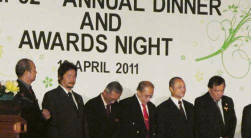
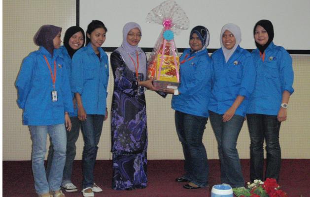
ieM 52nd annual Dinner 2011
by Ir. Dr Cheong Thiam Fook, Chairman Organising Committee, IEM Annual Dinner 2011
tHe Mechanical Engineering Technical Division (METD) volunteered to take up the task of organising the annual dinner with a single purpose and objective in mind, i.e . to raise more money through the selling of dinner tables from this special IEM event. The Organising Committee was formed and we established the theme of this annual dinner as "Engineers, Building a Sustainable Nation".
Many of us might have forgotten the Vision and Mission, Functions and Objectives of the Institution, so I am pleased to remind all of us that The IEM Vision is to be the premier professional organisation pivotal to Malaysia achieving Vision 2020.
Are we on-track to achieving this noble goal?
The objective of the IEM Annual Dinner has never been neglected although we have introduced many changes to the programme which received immense support from the Organising Committee, Committee Members and the IEM Secretariat.
All we hope to achieve is to create an avenue for the members to enjoy themselves in the most relax manner after years or months of hard work. There were more than 10 meetings or discussions attended by Committee Members and working groups who had contributed quite a few ideas towards making this annual dinner the most memorable one.
The highlights of the dinner included more entertainment than awards. On top of that, mysterious gifts were awarded to lucky members. More importantly, we held our dinner at the remote, green and less carbon polluted Putrajaya Marriott Hotel. We trust that you have also enjoyed the delicious food at the event n
notice
Habitat Magazine 2011
Members and readers are invited to submit articles to the Habitat Magazine 2011. Articles should be between 800 to 1500 words and submissions should be emailed to international@kpkt.gov.my by 30 June 2011.
Thank you.
IEM Editorial Board
IeM 52nd annual General Meeting and annual Dinner 2011
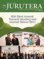
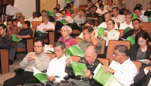
the Institution of Engineers, Malaysia’s 52nd Annual General Meeting (AGM) and Annual Dinner on April 16, 2011 was a huge success. In the morning, the Annual General Meeting, held at Wisma IEM, was chaired by Ir. Vincent Chen Kim Kieong, President for the 2011/2012 Session. Besides the normal agenda for the meeting, tokens of appreciation were also given to past Council Members and Past Presidents for their contribution to the Institution, followed by Ir. Chen’s Presidential Address 2011 entitled “Shifting Gears”.
In the evening, the IEM Annual Dinner was attended by members, spouses and guests at the Grand Putrajaya Ballroom, Putrajaya Marriott Hotel and Spa, IOI Resort City, Putrajaya. The Guest of Honour was Y.B. Tuan Chua Tee Yong, Deputy Minister of Agriculture and Agro-Based Industries of Malaysia. Other guests included heads of Government departments, statutory bodies, agencies; institutions presidents and vice chancellors of local institutions of higher learning as well as representatives of other professional bodies, universities, institutes and commercial establishments.
The Annual Dinner began with an opening address by IEM President Ir. Vincent Chen and a speech by the Guest of Honour, Y.B. Tuan Chua Tee Yong. While dinner was being served, the members and guests were entertained by Ms. Janet Lee with her backup dancers by IMG. During an interval, Ir. Chen presented the IEM Gold Medal Awards to the Best Final Year Engineering Students in local universities and institutions of higher learning for the year 2010/2011.
The recipients are listed as follows:
Chong Ee Lian, Universiti Putra Malaysia (UPM) (Aerospace)
Kiew Peck Loo, Universiti Sains Malaysia (USM) (Chemical)
Chua Yaw Choon, Leonard, Universiti Kebangsaan Malaysia (UKM) (Engineering and Built Environment)
Azizan Azwan bin Sapuan, Universiti Malaysia Sarawak (UNIMAS) (Mechanical and Materials)
Vignesh Kumar a/l Munusamy, Universiti Teknologi PETRONAS (UTP) (Chemical)
Kelvin Koh, Universiti Malaysia Pahang (UMP) (Mechanical)
Anis Nadhirah binti Ismail, Universiti Malaysia Perlis (UniMAP) (Material)
Sheikh Ezamuddin bin Sheikh Mohd. Mustaffa, Universiti Tun Hussein Onn Malaysia (UTHM) (Electrical and Electronic)
P. KDT Muhammad Syahir bin Badruddin, Universiti Pertahanan Nasional Malaysia (UPNM) (Electrical and Electronic)
Tay Bing Lin, Universiti Teknikal Malaysia Melaka (UTeM) (Electronic)
Lim Yi Fei, Multimedia University (MMU) (Electronic)
Chia Sing Ling, Monash University (Chemical)
Lana Wong Ying Qian, USCI University (Mechatronic)
Teh Sze Hong, University of Nottingham (Malaysia Campus)
Wong Shen Yuong, Universiti Tenaga Nasional (UNITEN) (Electrical and Electronic)
Zulkiffli bin Abdul Hamid, Universiti Teknologi MARA (UiTM) (Electrical)
Ang Cheng Cheng, University of Malaya (UM)
Pong Shyue King, Universiti Teknologi Malaysia (UTM) (Mechanical)
Chia Yee Shin, Universiti Malaysia Sabah (UMS) (Communication)
Toh Thiam Chai, Universiti Tunku Abdul Rahman (UTAR) (Electronic and Communications)
Yong Hui Li, Curtin University (Sarawak Campus) (Engineering and Science)
Lim Sheng Dar, Swinburne University of Technology (Sarawak Campus) (Mechanical Engineering)
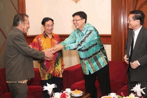
Among the numerous award presentations that night, Engr. Dr Nor Hayati binti Abdul Hamid was awarded the Raja Tan Sri Ir. Zainal Prize for the best technical paper on “A Concept Development and Proposed Design Procedure for Rocking Precast Hollow Core Wall in Warehouse” contributed by a Graduate Member in the Civil Engineering discipline.
The Tan Sri Ir. Hj Yusoff Prize, on the other hand, was awarded to Ir. Dr Ibrahim bin Kamaruddin for the best technical paper on “Fatigue Behavior of Fibre Reinforced Bituminous Mixture from Indirect Tensile Fatigue Test” contributed by a Corporate Member in the Civil Engineering discipline. Ir. Luk Chau Beng was also awarded the Tan Sri Ir. Hj Yusoff Prize for the best technical paper on “Doing Energy Conservation and Efficiency: The Passionate Way” contributed by a Fellow Member.
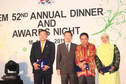
The Most Supportive Award for graduate membership was presented to Ir. Adnan bin Zulkiple for the individual category, while Dato’ Prof. Dr Mohd. Noh bin Dalimin, Vice Chancellor of Universiti Tun Hussein Onn Malaysia (UTHM) received the award for the organisation category on behalf of the university.
For the corporate membership category, Ir. Ruslan Abdul Aziz, Secretary BEM to receive the award on behalf of Jabatan Kerja Raya (JKR) for the organisation category. Puan Adelina binti Iskandar, Vice President of Corporate Affairs for Tenaga Nasional Bhd (TNB), represented TNB to receive the award for the most active organisation in IEM’s membership drive.
The IEM Presidential Awards of Excellence 2010 were
given to seven technical divisions for their active participation in the institution’s activities for the year 2010. Once again, the Mechanical Engineering Technical Division was declared the winner, followed by the Civil and Structural Engineering Technical Division and the Electrical Engineering Technical Division as the first and second runner up respectively.
The Project Management Technical Division was selected for the Most Improved Technical Division Award, while the fourth, fifth and sixth place went to the Geotechnical Engineering Technical Division, the Chemical Engineering Technical Division and the Building Services Technical Division respectively.
The IEM Excellence Performance in Fund Raising for the IEM Building was awarded to the top technical division which raised the highest amount of funds. The Mechanical Engineering Technical Division was declared the Platinum Winner having raised a total of RM60,000.
This year, for the first time, certificates of appreciation were given to the IEM Editorial Board Editors, namely, Engr. Abi Sofian bin Abdul Hamid for his role as the Bulletin Editor and Ir. Assoc. Prof. Dr Marlinda binti Abd. Malek for her role as the Journal Editor.
Earlier in the day during the AGM, a certificate of appreciation was also presented to Ir. Cheong Loong Kwong, Allen for his generous donation to the IEM Library. Last but not least, Ms. Ooi Beng Ean and Puan Halimah binti Musa from the IEM Secretariat each received a certificate for IEM’s Long Service Award. IEM members and guests then bid farewell with fond memories of an enjoyable evening. n
a
Summary of the IeM Presidential address 2011 entitled “Shifting Gears” by Ir. Vincent Chen Kim Kieong, President
for the 2011/2012 Session
IeM President Ir. Vincent Chen Kim Kieong began his Presidential Address by expressing his gratitude to Immediate Past President Dato’ Ir. Prof. Dr Chuah Hean Teik and the Council. He then proceeded to ask IEM Committees and Technical Divisions to take note of the composition of IEM’s Corporate Members and to tailor their activities to attract and benefit its members.
He also cautioned that, Council Members should always be mindful of the impact of decisions they make, especially those that directly affect the livelihood and professional wellbeing of a substantial number of IEM’s members. He also appealed to IEM members who are engineer owners of consultancies to join the ACEM. He pointed out that having a united and strong ACEM that represents the majority of consultants in the country would benefit the entire consultancy sector.
Ir. Chen also shared some compelling issues related to the engineering profession. He pointed out that, in recent years, there has been a trend among certain public agencies to enforce licensing or registration of subsectors within major disciplines. Although it is unfortunate that the isolated shortcomings of a few PEs are used to impose unnecessary licensing requirements to inconvenience and penalise the rest of the PEs, he stated that the isolated cases can be referred to the BEM for further and appropriate action.
In terms of education, Ir. Chen pointed out that engineering programs have mushroomed despite a dearth of experienced teachers of engineering. To maintain high teaching standards and the production of high quality engineering graduates, he believed that IEM should initiate a Code of Ethics for teachers of engineering.
Ir. Chen also brought up an issue that was close to his heart, i.e. the career prospects for engineers. He stated that, in the private sector, engineers can reach the highest echelon of the boardroom as directors, MDs or CEOs. However, the same cannot be said for engineers in the public sector.
He pointed out that the present structure of the public service does not provide any pathway for an Engineer to be considered for elevation to the highest Civil Service post as Ketua Setiausaha Negara (KSN) or even as Ketua Setiausaha (KSU). As such, he called for IEM to tackle and resolve this discrimination and eliminate the denial of opportunity of engineers in the public sector to reach their full potential in the service of the nation.
Ir. Chen also stressed that IEM must respond immediately to any engineering failures or disasters. He added that IEM must also ensure that the institution is up to date on all matters relating to policies and developments in engineering matters. To achieve this, the Executive Director, under the direction of the President, will be tasked with the assembling of all the necessary information, reports and relevant data to enable the Excomm and President to respond publicly to events and policies relating to engineering.
Lastly, Ir. Chen called for the full support of the Council, the Excomm and volunteers to take part in helping IEM go beyond its learned society role, and transcend to that of a Professional Institution to bring the greatest benefit possible to engineers, to the profession and to the country. He pointed out that, by enhancing the role of IEM as a Professional Institution, the institution can then be at the forefront of influencing engineering policies in the nation’s infrastructural development, in manufacturing and in engineering education.
recognising excellence
Dear Readers,
A successful organisation depends very much on the willingness of members to work as a team. This spirit will be reflected in every venture and occasion held by the organisation. For members with different professional background to have a common understanding, appreciation and the unity of thought is in itself a challenge. Everyone would like to contribute in his or her own way, which unfortunately could not happen all the time especially in team effort. A football team comprising good individual players does not make a champion if the players do not click with each other.
In order to inculcate and nurture this team spirit among members, the organisation will need to create a good platform for the members to channel their views. The leadership would then take heed of these views, giving appropriate attention whenever necessary.
Although this famous saying ‘ask not what your country can do for you but what you can do for your country’ is inspiring, the reality is that many people would expect the country or, in our case, the organisation to take care of its members. It is, therefore, heartening to note that the IEM President has outlined the need to look at certain requirements and regulations affecting practicing engineers as part of his goals.
by
Together with continuing education, better clarity would enable more engineers to have a better career path. The intention to respond immediately to engineering related issues especially in this country is a step in the right direction to ensure that the public is better informed and also to make the IEM a leading learned society. When these goals are achieved, it is hoped the engineers, especially members of IEM, will once again stand proud and be the first among equal in our society due to their excellence.
JURUTERA, being one of the easily accessible communication channels between the leadership and members of the IEM, will surely provide the required support to turn this vision into reality and accomplish the mission by promoting tools in the form of knowledge, information, motivation and even inspiration. n
Together We Excel!
Warm Regards, The Editor
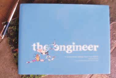
The cartoons appearing in Shaiky’s View are now available in a professionally designed, 28 x 22 cm hard cover coffee table copy titled “The Engineer”. This limited edition contains more than 180 cartoons dealing with engineering and construction.
“The Engineer” can be purchased through IEM for RM125, of which RM20 will be donated by the author to IEM funds. Please add delivery and handling costs of RM20** for Peninsular Malaysia and RM30** for Sabah and Sarawak.
Please make your cheque payable to “the institution of engineers, Malaysia” and mail it together with the following return slip to IEM Headquarters. For further enquiries, please write to sec@iem.org.my
(** Note: Cost is subject to the destination)
renewal of 2011 MeMbership fee
Effective from 1 January 2011, defaulting members in arrears of subscription will be considered as suspended members with all benefits removed. Consequently, these members will not be allowed to evening talks and will be charged the non-members' fee at the entrance. They will also not be entitled to register for visits/courses/seminars/conferences and any paid event of the IEM at members’ registration fee.
To avoid this, all IEM members are advised to settle their annual subscription on time and the deadline for payment each year is on 31 January.
Thank you.
Executive Committee of the IEM Council
Engr. Abi Sofian bin Abdul Hamid
view cartoon book
engineers and Public relation
engineers are known to be very comfortable with formulas and figures, and happy to design structures that will eventually benefit mankind. That is what they learn from the very first day at the university. When I was studying at the university more than 30 years ago, subjects on management, human or public relations were not part of the syllabus. These were things that an engineer learned and experienced after he graduated.
These are, in fact, part of the requirements for passing the Professional Membership of our engineering institutions including the Board of Engineers Malaysia. The professional experience in dealing with the public only begins when an engineer joins the workforce. This article intends to share the experience of the author in dealing with the public when he was a government engineer and also after retirement as an independent consultanting engineer.
a new engineer
A new engineer is normally a sheltered figure. He has a senior who will guide him in doing his job at the office, laboratory or even on site. Most likely, he will have a set of duties that have been earmarked for him. He may, at certain times, be required to accompany his senior or boss to attend meetings with clients and even the authorities. Only when his boss is confident that he is competent enough will he be allowed to attend such meetings on his own.
Dealing with technical matters or even legal matters is relatively easy compared to dealing with the public as the latter is more educated now compared to about 30 years ago. An engineer who has experience managing projects bordering residential areas or anywhere near where people reside knows how difficult it is to deal with neighbours compared to dealing with subordinates.
Dirty effluent discharge from silt pond, dust, noise and ground vibration from blasting work are some of the common complaints from them. While many of these complaints may be justified and deserve attention from the engineer in charge, the consequence may be disastrous if, for example, the authorities imposed a stop work order pending investigation. It is quite normal for the authorities to issue such an order to calm the situation. The loser will be the project proponent in terms of a delayed project and increase in cost.
the Public and the engineer
An engineer is normally a very respected figure because of his academic training and more so if he is a Professional Engineer or Consultant Engineer by virtue of his long training and experience. In the author’s experience in dealing with the public on mining, quarrying and construction blasting work, the projects that had the least problems with the public were those that engaged the neighbours from the very beginning.
We must be willing to show that we care for the neighbours and explain to them the benefits of the project, the effect of the project while it is ongoing and the mitigation measures undertaken to minimise the probable problems. The discussions need not be very detailed, but the concern of the engineer is most likely to be sufficient to cool the atmosphere when the actual trouble happens, if it really happens, such as in quarrying when flyrock incidence happens.
When this happens, the public would want an explanation from the engineer and not from the technician. A quarry that engages the public from the very beginning is more likely to receive friendlier treatment from them when trouble occurs. This is especially true in Selangor where many quarries are operating near residential areas. A similar situation arises when projects are carried out near established residential areas where people are affected by the increase in traffic from lorries carrying building materials, noise, pollution and danger from accidents.
The personal presence of the engineer is actually very important from a psychological point of view. However, the engineer must be well prepared with his expertise, and be well mannered and patient in dealing with the public.
ways to imProve relations with the Public
There are many ways to improve the relations with your neighbours and the public that engineers may not find in book. Some of them include:
1) Contribute generously, for example, by taking part in mosque activities especially during the fasting month (for Muslims) and attend events sponsored by your employer.
2) Show the neighbours that you are concerned about their wellbeing by conducting regular surveys on the effect of your project on them.
3) Get to know the village head, “penghulu”, “wakil rakyat” or other respected figures in the neighbourhood.
4) Encourage your staff to have, for example, tea at nearby stalls or where the neighbours congregate and communicate with them.
5) Send the senior engineer to attend meetings with the representatives of the neighbourhood to show them that they are important. Some government departments make it compulsory for the quarry operator to have regular meetings with the representatives of nearby residents to give them a chance to air their complaints.
All these activities actually show the public that we care about them. We benefit from their cooperation and they benefit from our presence from a business and also goodwill point of view. Engineers are part of the society and must be willing to engage them and show the public that they benefit from our presence. Only then can we earn their respect. n
by Ir. Hj. Look Keman bin Sahari
assessment Method for Course Outcome and Program Outcome in Outcome Based education (OBe)
by Ir. Zamri bin Mohamed
an accredited engineering program is judged as providing satisfactory preparation of graduates to initially enter the profession as registered engineers, and then develop their skills subsequently to the level of professional engineers (Javed et al 2009). The accreditation process is designed to publicly assure the competence of graduates, independent of the certification and credentials provided by the institutions of engineering education. According to the EAC Manual 2007, “Program Outcomes are statements that describe what students are expected to know and able to perform or attain by the time of graduation. These relate to the skills, knowledge, and behaviour that students acquire through the programme.” From the EAC Manual, students of an engineering programme are expected to attain 10 program outcomes as follows:
(i) ability to acquire and apply knowledge of science and engineering fundamentals;
(ii) acquired in-depth technical competence in a specific engineering discipline;
(iii) ability to undertake problem identification, formulation and solution;
(iv) ability to utilise systems approach to design and evaluate operational performance;
(v) understanding of the principles of design for sustainable development;
(vi) understanding of professional and ethical responsibilities and commitment to them;
(vii) ability to communicate effectively, not only with engineers but also with the community at large;
(viii) ability to function effectively as an individual and in a group with the capacity to be a leader or manager;
(ix) understanding of the social, cultural, global and environmental responsibilities of a professional engineer; and
(x) recognising the need to undertake lifelong learning, and possessing/acquiring the capacity to do so.
1.0 PraCtICaBLe aSSeSSMent In enGIneerInG PrOGraM
Assessment in Outcome Based Education (OBE) can be done in many different ways by the respective
institutions to reflect the process of Continuous Quality Improvement (CQI). Since the concept of OBE is relatively new, some may find that the assessment for OBE rather cumbersome and will take a lot of resources to keep track of students for every course at any given time. And this has to be done continuously for as long as the program needs to be accredited by the respective Engineering Accreditation Council as approved by the Washington Accord. The guide by the accreditation body is insufficient for any program owner to be confident of their assessment documentation. However, a method can be used to measure the achievement of the course outcome in relation to the program outcome which should meet the program objectives. The achievement of the program outcome needs to be measured so that continuous improvement can be done to upgrade the quality of engineering graduates.
There are two levels of assessment measurement; one is at the course level and the other is at the cohort level. For every course, the course attainment is recorded and later becomes an input to the cohort level assessment, which takes into account all courses taken by each cohort at any given semester. To ensure that the attainment is kept on record, several forms need to be produced by the course instructor and this will become the base for the next time when improvement needs to be done. The forms will include marks distribution and table for course outcome attainment as well as table for program outcome attainment.
2.0 COurSe OutCOMe MaPPInG tO PrOGraM OutCOMe
Course Outcomes from Fluid Mechanics 1 are taken as a sample to be analysed. There are five associated course outcomes as decided by the instructor. They are as follows:
CO1: Solve fluid statics based problems.
CO2: Solve fluid in motion problems.
CO3: Solve fluid friction in pipes problems.
CO4: Solve fluid flow measurement problems.
CO5: Apply the concept of dimensional analysis.
All of these Course Outcomes (CO) shall have linkage to Program Outcomes (PO) in such a way that the strongest emphasis has the value of 3, whereas the least emphasis is rated 1 (Table 1).
3.0 COurSe OutCOMe attaInMent
For the detail assessment division, Table 2 indicates the subdivision of each question or assignment that relates to the specific COs. As shown in the table, for Test 1 (T1), there are four questions; Q1 and Q2 is to assess CO1, while for Q3 and Q4, they are for CO2 assessment. Similar cases for Test 2 (T2) applies, two of them are designated to measure CO3 and another two for assessing CO4. In addition, all CO1 to CO5 are also measured using assignments (Asgn) and Final Exam (FE). The column ‘% Total’ contains ‘a’, ‘b’, ‘c’, ‘d’, ‘e’ which is the sum of each row normalised to 100. The column ‘result’ indicates whether each CO is achieved using the value from column ‘% Total’. The last column represents ‘Yes’ or ‘No’.
(Q1 from Test 1) + (Q2 from Test 1) + (A1 + A2) + (Q1 from Final Exam) ≥ 50%, then CO1 is achieved. To best visualise the arithmetic, it is easier to take each mark as the portion of mark towards the final course score. Q1 from Test 1 may contribute just 3% towards the overall final score. Q2 from Test 1 might contribute just 2% and Assignments 1 and 2 give another 4%, and lastly, Q1 of Final Exam constitutes 5%. So altogether, the total mark that justifies CO1 is only 14% from the final overall score. To be able to say that CO1 is achieved for any student, they need to get at least 7% so that it counts as 50% of total possible score for CO1. A similar assessment needs to be done on other COs so that all COs are evaluated.
To measure the attainment for each CO, it is imperative to decide on the appropriate value of marks that will indicate that the CO is achieved. For example, an average 50 out of 100 may be chosen as the minimum level of marks needed to be obtained by students. If that is so,
4.0 PrOGraM OutCOMe attaInMent
Next, the achievement of the COs needs to be linked to the achievement of the POs. To do this, value from Table 1 is used to calculate the score for PO. Table 4 shows the linkage from COs to the POs. The ‘CO Result’ column as shown is just an example of CO attainment. For this case, CO1, CO3 and CO4 are set as achieved, whereas CO2 and CO5 are set as not achieved.
Table 2: Detail assessment planning
Table 3: Individual CO calculation
Table 1: Relation PO-CO
From Table 4, for each of the CO that is achieved (Y), the weightage in the matrix is calculated towards the value of PO Attainment. From example, in Table 4, CO1, CO3 and CO4 is met, therefore the weightage is to be calculated from the overall sum of weightage for PO1. The bolded weightage represents the CO which is achieved.
For PO1, PO Attainment = (2+2+2) / Sum PO1_Weightage * 100 = 6 / 10 * 100 x = 60%
(Multiply by 100 to get the percentage of PO Attainment)
A similar calculation is done on PO5 and PO7. The calculated PO Attainment is only the partial contribution of one course towards the POs. In any case, all of the courses need to be evaluated the same way progressively. After getting the PO Attainment for all of the courses in the same semester, one can use the statistical method to determine the overall PO Attainment contribution for one semester. An average value may be used to get the distribution of the PO Attainment for all courses in one semester. Later, towards the completion of the four-year program, the program owner could get the overall PO Attainment for all the semesters. Only this final PO Attainment (for all semesters) can be considered as the POs measurement for any cohort or entry.
5.0 COnCLuSIOn
By adopting the OBE concept, one should at all times take measurement of the cohort progress. Any intervention can be done to improve the CO attainment as well as the PO attainment before the cohort finishing the program. After each cohort has completed the program, the overall PO Attainment can be based as a benchmark for the next cohort. In any case, the value or numbers from the PO Attainment is just a number, and it may bring meaning to some standard or it may be meaningless. Depending on what measures have been done to keep track of the process and quality, the PO measurement can ensure that the students produced have been included in the continuous quality improvement process and, therefore, by the very meaning of OBE, engineering students should be getting better from time to time. n
reFerenCeS:
[1] Engineering Programme Accreditation Manual 2007: Board of Engineers Malaysia (BEM), pp. 2-3: Appendix G.
[2] D. Andrich, “A Framework Relating Outcomes Based Education and the Taxonomy of Educational Objectives”, Studies in Educational Evaluation 28 (2002) pp.51.
[3] Javed A. Memon, R. Esra and B. S. Chowdhry, “Achievements, outcomes and proposal for global accreditation of engineering education in developing countries”, Proceeding of Social and Behavioral Sciences 1 (2009) 2557–2561
[4] Andrich, D. (in press). Implications and applications by modern test theory in the context of Outcome Based Education. Studies in Educational Evaluation.
Ballast Water management on ships
1.0 IntroductIon
Ballast, in practical terms, refers to the weight added to ships to maintain stability. From wooden ships to modern steel vessels, ballast addition has been a regular practice when a ship becomes light after discharging its cargo. When the vessel reaches port to load cargo again, this ballast has to be gotten rid of, a process which is known as deballasting. For a ship-owner, the carriage of ballast is an unproductive phase in ship, and for the ship’s personnel, ballasting and deballasting are inevitable exercises which add to the operational workload. As ships get bigger and deep drafted, the significance of ballast increased as ballast was carried not only for sea-going stability but also for propeller immersion.
Through the ages, wooden ships carried solid ballast in the form of stones, sand, tiles and heavy materials of sorts. When trading increased in volume and technology developed, steel ships replaced the wooden fleet. With riveting, followed later by welding techniques, assuring structural integrity, ships began to use seawater as ballast. Seawater was easily available and easily filled the tank spaces. The functional convenience of pumping the water made ballasting and deballasting quicker and easier.
Pumping rates can be in the high range of 5000-15000m3/ h [1] and large vessels typically carry a ballast of about 30 to 45% of their dead weight tonnage [2-3]. It is estimated that almost 3 to 5 billion tonnes of ballast water is being shifted annually around the globe [2]. Requirement for additional installed power and equipment, extra workload and tank corrosion have been identified as the harm caused by ballast water, but these voluminous shifts are causing another harm of greater concern, namely, ecological imbalance. This article attempts to bring awareness of the technological activities the shipping industry is currently experiencing due to this.
2.0 Harm of InvasIve specIes
The water which is loaded as ballast contain marine organisms of varying sizes, and these are carried and released with the water at the loading destination of the ship. The organisms are considered alien and, in most cases, are invasive in nature. Other than microorganisms, non-indigenous organisms such as mice, rats, cockroaches, jellyfish, crabs, fish etc ., are supposed to have been transported by ships [1].
by Mr. Rajoo Balaji
The impact of these biological invasions by way of spreading diseases, the extinction of native species and ecological imbalance etc ., came into strong focus in the 1980s. It is on record that remedial actions have cost millions of dollars. The European zebra mussel fouling of the Great Lakes, the finding of Japanese dinoflaggallates in Australia and the carnivorous North American jellyfish in the Black Sea can be cited as examples [4]. Table 1 highlights the harmful effects of some of the organisms. It is to be noted that these harmful effects and the species listing are neither exhaustive nor comprehensive. Of the environmental threats that are affecting the oceans of the world, the topmost four threats that have been identified are the shifts of species, land-sourced pollution, climate change and excessive fish harvesting [5]. In addition, shipping has been identified as a vector that contributes almost greater than 90% of the shifted species [6].
Table 1: Harm Caused by Marine Invasive Species [5, 11]
(Vibrio cholera)Cholera epidemic
Cladoceran Water Flea (Cergopogis pengoi)
Mitten Crab (Eiocheir sinensis)
Clogging of fishing nets, trawls etc
Invasive. Preys on native species and depletes population. Can travel inland through fresh waterways and affect food webs
European Green Crab (Carcinus maenus) Invasive. Preys on native species and depletes population
Zebra Mussel (Driessena polymorpha) Fouling, alteration of habitats
Asian Kelp (Undaria pinnatifida) Alteration of habitats
Toxic Algae
Oxygen depletion, release of toxins and killing of marine organisms. Consumption of contaminated seafood can cause illnesses and death in humans
3.0 Impact on malaysIan Waters and sHIppIng
Peninsular Malaysia, with its geographical location and total coastline of more than 4500km, harbours potential habitats which are being exposed to the species transported by ships. Apart from the threat faced by dependant
fishing activities, other sectors such as tourism, human health and the rich biodiversity will also be harmed. The Malacca Straits experiences an average of 600 ships/day and up to 70000 passages have been recorded annually[5]. An increase in the number of ports and trade has also further increased the number of ships plying these waters. Realising the vulnerability of the situation, Malaysia has been proactive in addressing the concerns of the international shipping community and has laid out regulations typically in alignment with many other countries [7].
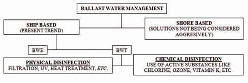
4.0 Ballast Water management (BWm): current practIces
The International Maritime Organisation (IMO) has initiated measures to mitigate this harm. Although the IMO Convention awaits full ratification, the industry has been gearing itself for the regulations. Two approaches have evolved, of which one is purely operational, while the other is based on water treatments which are trying to address the standards on species count set by IMO as shown in Table 2. It needs to be mentioned that standards set by some of the US States are stricter. The Convention for the Control and Management of Ships’ Ballast Water and Sediments (BWM Convention) of 2004 targets 2016 for ships to fully comply with the Regulation D2 Standards as projected in Table 2.
Table 2: IMO ballast water performance standards organism size class
Organisms greater than 50μm in minimum dimension <10 cells/m3
Organisms 10-50μm in minimum dimension <10 cells/ml
2. cfu: Colony Forming Unit. A measure of viable bacteria numbers.
3. μm: One millionth of a metre
The operational approach, which is presently being followed by many ships, involves exchanging the ballast water as the ship moves in the sea. When the ship reaches the load port, the ballast water which is pumped out will not be the water loaded at the discharge port. The principle of this method is based on the premise that species from coastal waters cannot survive the deep ocean ambience. Furthermore, the densities of species in open seas are much lesser than that of coastal waters, so the water exchanged in the open seas will have a very low percentage of species.
(To be continued at page 20)
1Sudoku centerpiece "1"
by mr. lim teck guan
About the puzzle:
In this Sudoku variant, only 1 number is given as clue, thus the name 1Sudoku. The rest of the clues are given in the numbered cages (the dotted frame encompassing 2 or more squares). You are to search for the right combinations to fit the total for the cages and end up with a Sudoku Grid, the 9 by 9 composite of squares where there is no repeat of the number 1 to 9 in every Row, Column or Block.
Fill in the remaining 80 squares with single digits 1-9 such that there is no repeat of the digit in every Row, Column and Block. The number at the top left hand corner of the dotted cage indicates the total for the digits that the cage encompasses.
for tips on solving, visit www.1sudoku.com.my Twin Tree Publishing Answer is in the following pages of this edition.
Author could be contacted at rajoobalaji@alam.edu.my.
Two broad methods of ballast water exchange (BWE) are being followed, namely, the Flow through Method and the Sequential Method. In the Flow through Method, water is pumped in through the tanks’ bottoms and the water already present in the tank is displaced by overflowing the tank. The Sequential Method involves replacing water from the tanks in a sequence. Both the BWE methods, though simplistic, have serious issues. Apart from the additional workload for the ship’s personnel, the efficiencies have proven to be inconsistent [8] and have also shown excessive hull girder stresses due to the volume/weight shifts [9]. Other exchange practices basically follow one of these methods with some variation in approaches. Considering the demerits and requirement for a stricter regimen, treatment technologies are being developed. The technologies require type approval and many solutions are
commercially available to ship-owners. Figure 1 shows the BWM options.
5.0 Ballast Water treatment (BWt) tecHnologIes
Though possibilities of shore based treatment are being debated, the orientation has been towards shipboard management of ballast water by treatment methods replacing exchange methods. Almost all the BWT solutions have been developed from the experience of wastewater management technologies and most of the solutions are a combination of two to three technologies. The capital and operating costs of these emerging technologies are very high. On average, the operating costs average $30 to $130 per 1000m3/hour of treated water [10]. Capital costs range from $287,000 to $779,000, depending on the flow rates [10]. The reasons for the high costs may be attributed to the newness and recovery of research costs, apart from the conventional costing factors. Though both physical and chemical methods are effective in species elimination, chemical methods fare better in comparison. The recurring costs of chemicals, storage, harm to human health and other marine life are some of the looming concerns of the chemical methods.
Separation
UV Radiation
Separation of solid particles due to centrifugal forces
Acceleration of the water by internal flow direction inside the facility
Inactivation of organisms and pathogens by breaking the cell membrane
Cavitation Slit plates or venturi pipes generate cavitation bubbles
High local energy due to implosion of bubbles inactivate organisms
Electrolysis
Electronic ionisation by means of electric current
Generation of chlorine/chlorine dioxide as disinfectant
Chemical AdditivesDirect addition of chemical additives to the ballast water that have disinfector actions
De Oxygenation
Gas Super Saturation
Removal of dissolved oxygen in ballast water and replacement by inactive gases
Thermal TechniquesHigh temperature sterilisation of water
Electric pulse and pulse
plasma techniques
/20μm
Established technology
UV radiation at approx. 200nm. can destroy cellular components
Low pressure drop in water system
Acoustic Systems:
Transducers apply sound energy at specified amplitude and frequency
Sound energy causes cavitation. Resulting mechanical stresses disrupt the cells
Oxidising and nonoxidising biocides:
Chlorine and ozone are the widely used oxidising biocides
Organic structures like cell membranes destroyed by strong oxidisers
Nonoxidising biocides interfere with reproductive, neural, metabolic functions
Applicable for big volumes
With removal of oxygen, most of the organisms (exception: cysts, spores or anaerobic bacteria)
Oxygen can be removed by introducing inert gas or by addition of chemical additives
Controlled atmosphere in tanks is needed to avoid re-oxygenation
Use of heat source from ships
Application of electric field or pulse to kill organisms
Magnetic FieldsWater is passed through ferromagnetic/ electromagnetic devices.
Magnetic flux supposedly alters the organic and inorganic constituents
Biological TechniquesControl of organisms achieved by introducing additional organisms (predators, pathogens or competitors of concerned species)
Anti-fouling coatingsReduces biological fouling by toxicity, ablation or surface activityExpensive
Banned for use on ship’s under-water hulls
Figure 1: Ballast water management - Present options
Table 3: BWT: Cognisable technologies in contention
Some of the chemical systems, like those employing chlorine, require end control to reduce the harmful percentage of the chemical prior to discharge. Table 3 highlights most of the technologies being researched and adopted.
6.0 conclusIon
Globally and locally, the shift of invasive species through ballast water has been recognised as a problem of
references:
[1] National Research Council Report (NRC Report) (1996). Stemming the Tide: Controlling Introductions of Non-indigenous Species by Ships’ Ballast Water. National Research Council Staff. National Academies Press, Washington, D.C., Pp.1-72.
[2] IMO (2004). International Convention for the Control and Management of Ships’ Ballast Water and Sediments, London, 2004. International Maritime Organization. Pg. 38.
[3] AQIS, Australian Quarantine and Inspection Service (1993). Ballast Water Management, Ballast Water Series Report No.4, AGPS, Canberra.
[4] Harbison, G.R., and Volovik, S.P., (1994). The ctenophore, Mnemiopsis leidyi, in the Black sea: A holoplanktonic organism transported in ballast water of ships. Proceedings of the National Oceanic and Atmospheric Administration Conference and Workshop on Nonindigenous Estuarine and Marine Organisms. Washington, D.C.: U.S. Government Printing Office. Pp. 25-36.
[5] Kaur, C.R., (2010). Malaysia and the Ballast Water Management Convention: An Analysis, Journal of Sustainability Science and Management 2010, Vol. 5 (1), Pp.125-137.
serious concern. As of 30 September 2010, 27 countries representing 25.32% of the world’s tonnage (IMO) have ratified the BWM Convention, whereas a minimum number of 30 countries representing not less than 35% of the gross tonnage are required for full ratification [11]. New treatment technologies and those highlighted herein will witness research activities on grounds of economic and technological viabilities. n
[6] Hayes, K. R and Sliwa, C., (2003). Identifying potential marine pests: a deductive approach applied to Australia, Marine Pollution Bulletin 46 (2003), Pp.91-98.
[7] Malaysian Shipping Notice, MSN 48/2008.
[8] Murphy, K.R., Ritz, D. and Hewitt, C.L., (2002). Heterogeneous zooplankton distribution in a ship’s ballast tanks. J. Plankton Res. 24 (7), Pp.729–734.
[9] Rigby, G.R. and Hallegraeff, G.M., (1994). The transfer and control of harmful marine organisms in shipping ballast water: behaviour of marine plankton and ballast water exchange on the MV ‘‘Iron Whyalla’’. J. Mar. Environ. Eng. Vol. 1, Pp.91–110.
[10] Lloyd’s Register Report. 2010. Ballast Water Treatment Technology, Current Status. February 2010. Third Edition. Pp.7-35.
[11] www.imo.org. GL Report. 2009 and Status of Conventions. Last accessed 03 Oct. 10, 14:22 hrs, LT, Malaysia.
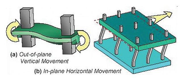
electrostatic separation technology for Water-in-oil Dispersions / emulsions
the CompaCt Centrifugal eleCtroCoalesCer-separator
In the oil and gas industry, mining and extraction industries, chemical process industries, and biomedical and pharmaceutical industries, there are many processes where water drops are finely dispersed in an oil phase to enhance mass transfer of chemical species. Subsequently, the water drops may have to be separated from the oil for the downstream operation. A number of separation methods may be used such as gravitational settling, centrifugation, hydrocyclones, membrane filtration and electrostatic separation, depending on the size of the water drops and the properties of the two phases [1, 2, 3].
Gravitational sedimentation has a wide range of applications, such as the removal of solids from liquid sewage wastes, the settling of crystals from liquor, and the separation of a liquid-liquid mixture in solvent extraction [1]. However, gravitational separation usually becomes difficult when the density difference between the two phases is very small, when the continuous liquid is highly viscous, and when the dispersed phase is of very small drops. The separation can also becomes highly complicated when the very small dispersed drops are covered by layers of impurities such as surface active agents, asphaltenes and resins, making the drops repel each other and thus remaining stable in the dispersions [4, 5, 6].
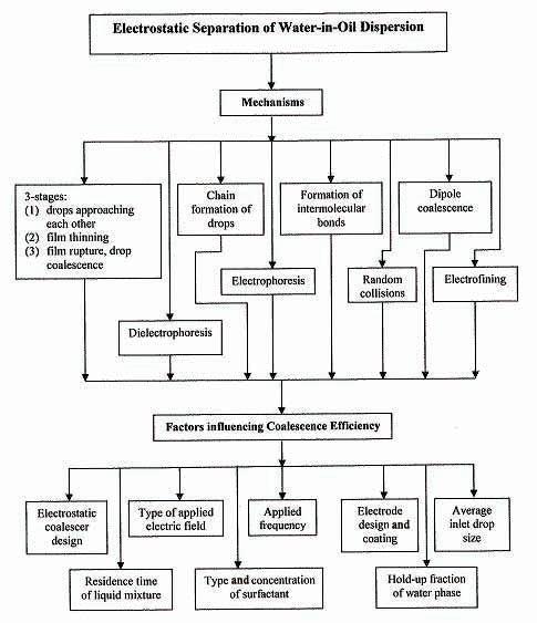
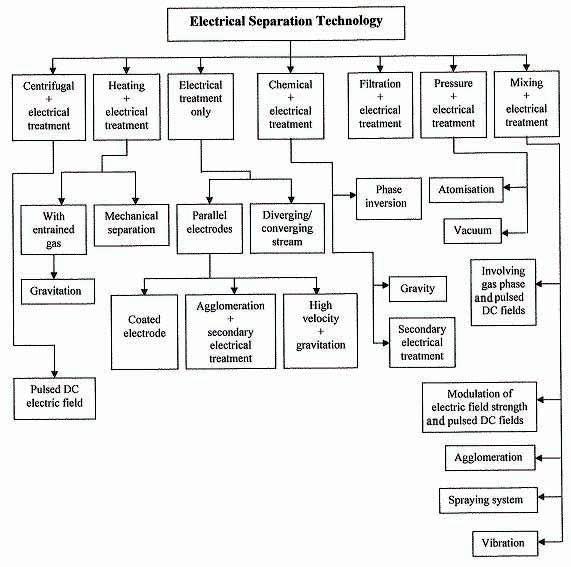
In the oil and gas industry, a separation method based on the different electrical properties of the two phases is employed to separate water-in-oil dispersions [7, 8]. The underlying mechanisms of the electro-separation technique are summarised in Figure 1 [9], and its practical aspects used in the oil and gas industry are summarised in Figure 2 [2].
Electrostatic separation of water-in-oil dispersions has a number of advantages, such as low power consumption due to very low electrical current used, no addition of chemicals is required, and the method is free from mechanical break down as no moving parts are involved [8, 10]. In this article, a compact electrocoalescer-separator [11], together with the electrical effects that enhance the separation of water-oil dispersions, are highlighted.
the CompaCt Centrifugal eleCtroCoalesCer-separator
The design and performance of a compact centrifugal electrocoalescer-separator [11] combined electrocoalescence with centrifugal forces to separate dispersed water drops from the flowing viscous oil, with the two liquids having a very small density difference.
by Ir. Dr Eow John Son
Figure 2: Various combinations of electrical separation technology [2]
Figure 1: Mechanisms and factors influencing the electrostatic separation performance [9]
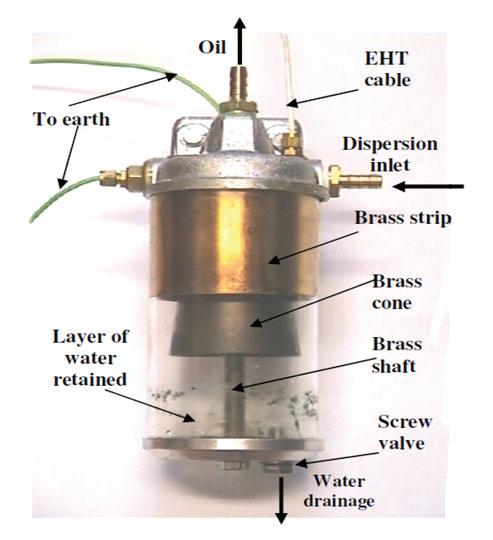
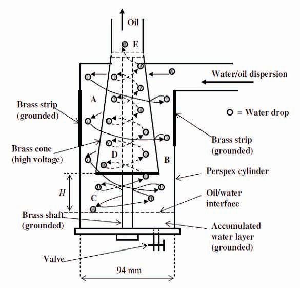
Figure 3 shows the water-oil separator based on the centrifugal action and equipped with electrodes to enhance the separation [11]. The brass cone is connected to a high voltage supply with positive polarity, while the brass strip and the brass shaft are grounded. There are a number of regions of high electric field intensity: (i) between the brass cone and the middle shaft, (ii) between the cone and the copper strip, and (iii) between the base of the cone and the accumulated water layer at the bottom of the separator. The water-in-oil dispersion enters the upper part of the cylindrical section tangentially, causing centrifugal or swirling motion, therefore forcing the heavier water drops to move to the cylinder wall where they coalesce rapidly under the influence of the pulsed DC electric field. Drop-interface coalescence also takes place in the bulk water phase at the bottom of the separator. As there are no moving parts in the system, the necessary vortex motion is performed by the liquid itself.
The fundamental mechanisms in the electrocoalescerseparator are drop charging and drop-drop coalescence, followed by drop-interface coalescence [9, 10, 13, 14].
The height of the accumulated water layer at the bottom of the separator can be controlled by a valve to facilitate the investigation of the effect of H (i.e. the distance between the oil-water interface and the bottom of the brass cone) on the efficiency of the separation of water drops from the flowing oil. The accumulated water phase, which is
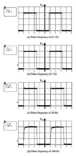
more conductive than the oil phase, at the bottom of the separator acts as a grounded ‘electrode’; it also facilitates drop-interface coalescence for the removal of the dispersed water drops from the flowing oil. A pulsed DC electric field can be applied to the brass cone. Square pulses of different frequencies are shown in Figures 4(a, b, c and d).
The separation efficiency of the electrocoalescerseparator can be defined as:
Separation efficiency (%) = ––––––– × 100 (1)
with Win as the inlet flow rate of the water drops, and Wretained is the amount of water phase retained by the separator per unit time.
Figure 5 illustrates schematically the movement of water drops in the centrifugal electrocoalescer-separator. The water/oil dispersion enters the separator tangentially, inducing a swirling flow. However, if the drops enter near the cylindrical wall, they could be dispersed radially inwards due to the high turbulent mixing in the feed section. Away from the feed section, as the water drops are denser than the oil, they move towards the wall due to the centrifugal effect.
In the absence of an applied electric field, a water drop within the flow is basically exposed to (i) gravitational and centrifugal forces, and (ii) the drag exerted on the water drop by the flowing oil. In the presence of an electric field, water drops coalesce rapidly and become larger, and at the same time, deviate more than in the previous case from the fluid stream line. In Region A, some of the drops are charged by contacting the high voltage brass cone, while other drops are polarised. Under a suitable electric field, drop-drop coalescence takes place in this region, and some drops that go into Region B are significantly larger than the average inlet drop size.
In Region C, a water drop either moves towards the oilwater interface or moves upward to the inside of the brass cone. This depends largely on the flow rate, the applied electric field, and the drop size. If the flow rate is too high, most of the water drops will flow with the continuous oil
Figure 3: The centrifugal electrocoalescer-separator that combines electrostatic and centrifugal separation forces [11]
phase into the cone. By increasing the applied electric field strength, it has been observed that more water drops tend to move to the oil-water interface due to an increase in the electrical-induced attractive force between the drops and the interface. Rapid drop-interface coalescence then takes place. The distance, H, between the bottom of the brass cone and the oil/water interface can be controlled by the valve at the bottom of the separator. Drops that do not coalesce with the oil/water interface will flow into the brass cone in a swirling motion. Drop-drop coalescence may also occur in the Regions D and E, as a number of drops in the outlet have been observed to be larger than the drops entering the bottom of the cone.
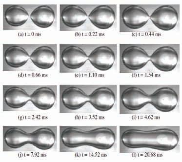
Generally, decreasing the H will increase the separation efficiency. For inlet water drops of 0.55mm diameter and H = 15mm, the optimum separation efficiency is about 65%, which occurs at the applied potential of about 3 kV. When H is increased to 55 mm, the optimum efficiency reduces to a maximum of about 40%, which occurs between the applied potential of 4 kV and 5 kV. However, when the magnitude of the applied electric potential is further increased beyond these values, the separation efficiency is observed to decrease. This might be due to the fact that high electric field can deform and finally break up aqueous drops into smaller drops [15].
Figure 7: Attraction leading to coalescence between two water drops at θ = 53o, 39o, 32o and 171.5o, and applied electric field of 1 kV/cm
Figure 8: Attraction leading to coalescence between two water drops at θ = 0.5o, and applied electric field of 1 kV/cm
Figure 9: Deformation and break-up of a water drop at applied potential 4.5 kV
Figure 4: The shape of the applied pulses at the applied potential of 3 k
Figure 5: Movement of the water drops in the electrocoalescer-separator
Figure 6: The grade efficiency curve at pulsing frequency of 100.0 Hz and H = 15 mm for the electrocoalescer-separator
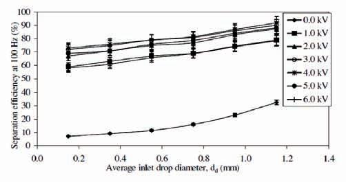
When the pulsing frequency is further increased from 50 Hz to 100 Hz, there is very little change in the observed grade efficiency, as shown in Figure 6 at H = 15 mm. At the applied pulsing frequency of 100 Hz, for the inlet drop size of 0.15 mm and the applied potential of 1 kV, the separation efficiency is about 58 %, compared to that of about 55% for the applied frequency of 50 Hz. As for the pulsing frequency of 50 Hz, the separation efficiency for the frequency of 100 Hz has also been shown to increase with the applied potential until 4 kV, beyond which the efficiency of the separator decreases. At the optimum applied potential of 4 kV, the maximum separation efficiency is about 93% when the average inlet drop diameter is 1.15 mm, for the pulsing frequency of 100 Hz. The separation efficiency is about 90% under the same conditions but with the pulsing frequency of 50 Hz. At the applied frequency of 100 Hz, the grade efficiency at the applied potential 6 kV is very similar to that at 1 kV for the various inlet drop sizes. Moreover, the applied potential of 5 kV produces similar separation efficiency to that produced by the potential of 2 kV for the inlet drop sizes shown in Figure 6.
Drop-Drop CoalesCenCe proCess
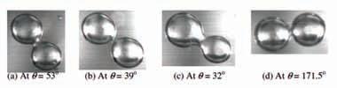
It has been shown that the applied electric field will enhance drop-drop coalescence, provided that the field is applied in a certain direction to the flow direction of the drops [12]. To achieve maximum force of attraction between adjacent water drops, the electric field should be applied in such a way that it makes a 0° angle with the line joining the centres of the drops. When the two water drops become very close together, drop-drop coalescence occurred, as shown in Figures 7 (a to d) at different angles at an applied field strength of 1 kV/cm.
For water drops dispersed in viscous oil, the drainage of the film separating the two drops is the bottle-neck of the overall coalescence process. Once this film is broken, drop-drop coalescence can then occur rapidly, as illustrated in Figures 8 (a to l).
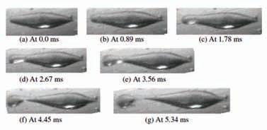
Deformation anD Break-up of Water Drops
The separation of a water drop from the oil depends on the drop’s trajectory and the deviation from its original trajectory due to external forces. However, deformation and break-up of a water drop can occur under a very high electric field, as shown by Figures 9 (a to g). The time required for complete detachment of a droplet from a 1 mm water drop in sunflower oil under an electric field of 4.5 kV/cm is about 4.45 ms. Before the droplet is detached, the main drop is stretched by the electric field into a prolate body, forming an elongated end [15]. The breakage occurs at the weakest point of the elongated end, as shown by Figure 10 (f), producing a smaller droplet, whose size depends on the breaking point of the elongated end [15, 16]. This could be due to the overwhelming electrical-induced stresses at the water drop-oil interface, thereby diminishing the force balance between the interfacial tension and the electrical-induced stresses.
Besides the electrostatic effect, the flow in the separator may have the potential for breaking the suspended drops due to: (1) transient shear and local pressure fluctuations caused by turbulence, and (2) viscous shear as a result of time-average velocity gradients. Possible turbulent shear stress and energy dissipation in the entry can affect the size of the drops, with
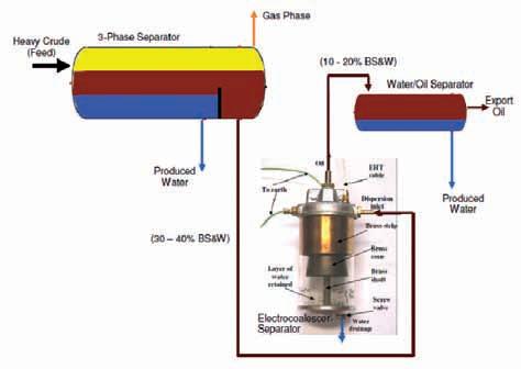
Figure 10: Application of Electrocoalescer-Separator in treating heavy crude oil
large drops stretched by turbulent vortices and broken up into smaller drops. High turbulence can also cause diffusion and modify the ideal settling motion of small drops within the separation region, with turbulent diffusion having a significant effect in liquid-liquid dispersions as compared to solid-liquid dispersions [17]. This is because the inertia of a drop is smaller than that of a similar size solid particle, due to the small density difference of the liquids. A drop will therefore be more sensitive to the turbulent motion of the continuous liquid.
appliCation in the oil anD gas inDustry
The electrocoalescer-separator can be further developed as a high-performance compact solution to treat heavy crudes into export-quality oil. This will have the advantages of lower chemicals consumption, power consumption and operating temperature, and better safety towards short-circuiting. The specific application is as illustrated in Figure 10.
The crude oil (containing 30 to 40% BS and W) from the conventional 3-phase separator will flow into the compact Electrocoalescer-Separator, which will take out a major portion of the water content. As a result, the treated oil exiting the Electrocoalescer-Separator will only contain 10 to 20% BS and W. Moreover, the remaining water droplets in the treated oil are charged / polarised by the applied pulsed DC electric field, enhancing drop-drop and dropinterface coalescence in the downstream water/oil separator. As such, a lower retention time is required, resulting in the smaller water/oil separator. This directly reduces the footprint, weight and capital costs of the equipments.
ConClusion
The compact electrocoalescer-separator, with an optimum electric field, has been proven to produce good separation efficiency for water drops dispersed in flowing viscous oil. The swirling motion distributes the dispersed water drops uniformly within the separator. Moreover, the water drops, having larger centrifugal forces due to the swirling effect, move rapidly towards the grounded brass strip, facilitating drop-drop coalescence and water-oil separation.
The separation efficiency increases with the applied electric field strength until a certain limit. Above this critical electric field strength, drop deformation and breakup occurs, generating smaller drops, and thus reducing the separation efficiency. An optimum electric field strength and an optimum pulsing frequency have been observed to exist with pulsed DC electric field for the enhancement of drop-drop and drop-interface coalescence in the compact electrocoalescer-separator.
The inlet drop size has a significant influence on the separation efficiency. Above a certain inlet drop size (>1.2mm), the separation efficiency will be very high even in the absence of electric field. However, for small inlet drops (< 0.8-mm diameter), the applied electric field plays a significant role in the separation process. The layer of the water phase accumulated at the bottom of the separator plays a vital role in capturing the dispersed water drops from the flowing oil.
The compact electrocoalescer-separator can be further improved for offshore and onshore installations to reduce the water content of crude oil, especially in the crude oil dehydration and desalting process. Moreover, the separator can be easily installed into existing process lines to separate water drops from flowing oil, in other industries, such as biodiesel production, palm oil refining, oleochemical processing, etc. For more information on the electrocoalescerseparator technology, the author can be contacted by email at johneow@hotmail.com n
referenCes:
[1] Geankoplis, C.J., Transport Processes and Unit Operations, 3rd Ed., Prentice Hall, New Jersey (1993).
[2] Eow, J.S. and M. Ghadiri, “Electrostatic enhancement of coalescence of water droplets in oil: A review of the technology”, Chemical Engineering Journal, 85 (2002) 357-368.
[3] Eow, J.S., Ghadiri, M. and A.O. Sharif, “Electro-Hydrodynamic Separation of Aqueous Drops from Flowing Viscous Oil”, Journal of Petroleum Science and Engineering, 55 (2007) 146-155.
[4] Thompson, D.G., A.S. Taylor and D.E. Graham, “Emulsification and demulsification related to crude oil production”, Colloids and Surfaces, 15 (1985) 175-189.
[5] Fingas, M., “Water-in-oil emulsion formation: A review of physics and mathematical modelling”, Spill Sci. and Tech. Bulletin, 2 (1) (1995) 55-59.
[6] Nelson, R.D. Jr., “Powders handling - dispersion of powders in liquids”, in Kirk-Othmer Encyclopedia of Chem. Tech., 4 th Ed., 19 (1996) 1093-1112.
[7] Less, S., Hannisdal, A. and J. Sjoblom, “Dehydration efficiency of water-in-crude oil emulsions in alternating current electrical fields”, J. Disper. Sci. Technol., 29 (2008) 106-114.
[8] Less, S., Hannisdal, A., Bjorklund, E. and J.Sjoblom, “Electrostatic destabilization of water-in-crude oil emulsions: Application to a real case and evaluation of the Aibel VIEC technology”, Fuel, 87 (2008) 2572-2581.
[9] Eow, J.S., Ghadiri, M., Sharif, A.O. and T.J. Williams, “Electrostatic enhancement of coalescence of water droplets in oil: A review of the current understanding”, Chemical Engineering Journal, 84(3) (2001) 173-192.
[10] Midtgard, O.M., “Electrostatic field theory and circuit analysis in the design of coalescers with pulsed dc voltage”, Chem. Eng. J., (2009) 168-175.
[11] Eow, J.S. and M. Ghadiri, “Electro-mechanical coalescer-separators for the separation of aqueous-in-oil dispersions”, UK Patent GB2377397A (15 January 2003).
[12] Eow J.S. and M. Ghadiri , “Drop-drop coalescence in an electric field: The effects of applied electric field and electrode geometry”, Colloids and Surfaces A: Physicochemical and Engineering Aspects, 219 (2003) 253-279.
[13] Eow, J.S., Ghadiri, M. and A.O. Sharif, “Electrostatic and hydrodynamic separation of aqueous drops in a flowing viscous oil”, Chemical Engineering and Processing, 41 (2002) 649-657.
[14] Eow, J.S. and M. Ghadiri “The behaviour of a liquid-liquid interface and drop-interface coalescence under the influence of an electric field”, Colloids and Surfaces A: Physicochemical and Engineering Aspects, 215 (2003) 101-123.
[15] Eow, J.S., Ghadiri and M., A. Sharif , “Experimental studies of deformation and break-up of aqueous drops in high electric fields”, Colloids and Surfaces A: Physicochemical and Engineering Aspects, 225 (2003) 193-210.
[16] Charles, G.E. and S.G. Mason, “The coalescence of liquid drops with flat liquid/liquid interfaces”, J. of Colloid Science, 15 (1960) 236-267.
[17] Malhotra, A., R.M.R. Branion and E.G. Hauptmann, “Modelling the flow in a hydrocyclone”, Canadian Journal of Chemical Engineering, 72 (1994) 953-960.
talk on “Gerbang Selatan Bersepadu –Medium term Link”
by Ir. Ong Sang Woh
the Gerbang Selatan Bersepadu (GSB) - Medium Term Link evening talk organised by the Civil and Structural Engineering Technical Division was held on 2 November 2010 at Wisma IEM and attended by 58 participants.
The speaker, Ir. Teh Tzyy Wooi, opened the talk by giving a brief overview of the GSB – Medium Term Link development project. The Medium Term Link (Inbound and Outbound) provides direct access to the Malaysian Customs and Immigration Building in Johor Bahru and links the existing causeway to Singapore. The project consists of six viaducts/bridges of precast segmental box girder integral with single pier column and portals.
The speaker highlighted the constraints of the existing launcher capacity of 65 Mtons, which restricts the design dimensions of the segmental box. The required width of the segmental box is 16.88m and the segmental length is limited to less than 2.2m since this is dependent on the segmental depth and web thickness. Concrete Grade 50/20 is used for the precast segmental box girder.
The design criterion is based on the BD 37/01, BS 5400 and JKR terms of reference. The design assumptions are as follows:
1) Seismic Load - 10% of the permanent dead load and superimposed dead loads + 20% of longitudinal HA traffic loading in all notional lanes.
2) Crack Width of 0.25mm (for Semi Permanent Bridge) and 0.1mm (for Permanent Bridge).
3) All piers/portals shall be designed as monolithic except for the abutment and existing piers and portals.
4) External pre-stressed shall be used for continuity tendons (bottom tendon).
The analysis of the Superstructure Design is summarised in the following steps:
• Analysis was carried out using Midas Civil.
• Design and Erection using the Balanced Cantilever Method.
• “False Cantilever” was used for the Split Pier or Split Portal.
• Cantilever Internal Tendons were used during the Cantilever Erection Stage.
• Top and Bottom Continuity Tendons for the Continuity Stage.
• All top Continuity Tendons were Internal Pre-stressed.
• Bottom Tendons were Externally Pre-stressed. However, External Bottom Tendon alone was found to be insufficient during the design stage. As such, bottom internal tendon (four strands of 15.7mm dia) was introduced. Maximum tendon size is limited to19 strands of 15.2mm dia.
The speaker informed the participants that there are normally two concepts of stressing the continuity tendons in Balanced Cantilever Box girder design. These are:
1) Stress the continuity tendons at the stitch as much as possible after concreting. This approach was adopted for this project.
2) Minimal stressing of the continuity tendons (one or two pairs of tendon) at every stitch. Then stress all the continuity tendons upon completion of all stitches.
The details on the Transverse Analysis and Pre-stressed Design involved the following steps:
• Using finite plate elements in Midas - Model on Bridge 1.
- To get Self-Weight, Dead Load, SIDL and Live Load’s Moment and Shear result.
• Using Beam Element for PS analysis and spreadsheet for design.
The speaker showed typical drawings for the design segmental box segments and explained the components and details of the box segment. Photographs of the inside of the box segment and the anchorage details of the tendons were emphasised. The animation on the sequence of segments erection using the launching gantry was also explained. Questions on shallow depth beams, shear key design and shear lag effects, over pre-stressed sections and crack width were clarified with the audience. The speaker covered the analysis of the Superstructure Design and the Transverse Analysis and Pre-stressed Design work and highlighted numerous hands-on experiences encountered during the GSB – Medium Term Link project. n
CiviL and StruCturaL enGineerinG teChniCaL diviSion
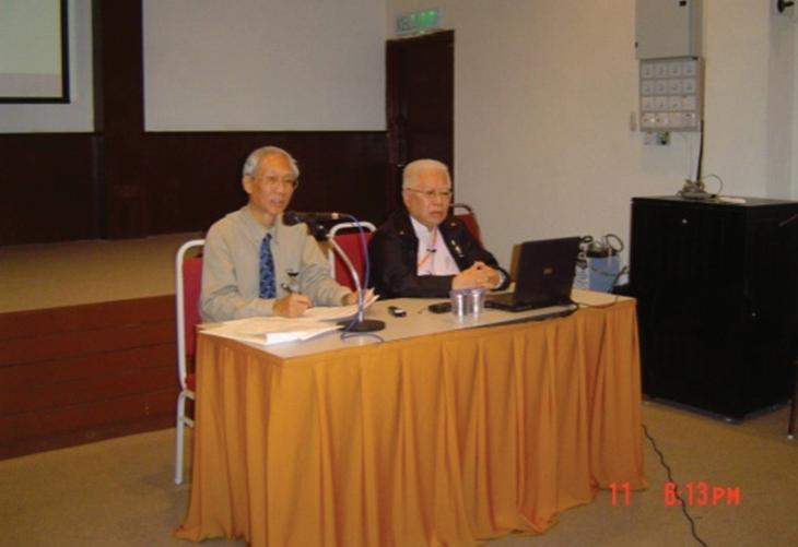
t he talk was conducted by Ir. Rocky HT Wong at the Tan Sri Prof. Chin Fung Kee Auditorium, Wisma IEM, on 11 November 2010. He kicked off the talk with an enlightening introduction on who actually practices Integrated Engineering Services. Practitioners of Integrated Engineering Services are progressive engineers who provide leadership to other engineering services professionals (ESPs) that make up the Engineering, Technology and Innovation (ETI) team, who have updated and enhanced their traditional engineering services (CPC 8672) to manage multidisciplinary Science, Engineering and Technology (SET) projects. These projects could be PMC and/or EPCC.
He highlighted the subtle difference between EPCC and the Design Build Contract. The former is a professional services-driven delivery system being engineering-led, whilst the latter is more of a skillsdriven effort supplemented with and complemented by the design outsourced to CPC 8672 for Engineering Consultancy Practices ( i.e . ECPs).
Project (or Program) Management normally employs software tools such as Program or Project Evaluation and Review Technique (PERT), Critical Path Method (CPM) or EVA/EVM. Nevertheless, it is more important to have the ability to apply special knowledge and
methods in the areas of ‘Planning, Organisation, Control and Execution’. He stressed that “the crux of control is management, not paperwork. It involves analysing the situation, deciding what to do and doing it!”
He then introduced the outcome based on a balanced ‘People, System, Organisation’, PSO-centric approach to Project Management. This approach provides the basis of a Goal Directed Project Management (GDPM) with the application of a milestone plan and responsibility chart for all project stakeholders.
Ir. Wong also introduced the concepts of ‘Leadernonomics’ and ‘Terotechnology’. He also expounded phrases such as “Great leaders spend time with their people” and “At the heart of the matter, most people stay if bosses ‘Know, Focus, Care and Grow’ their employees”.
The speaker concluded that “Street smart is more important than knowing a lot or too much!” ECPs and other Engineering Services Providers who find themselves in the crowded and lower end of the competitive spectrum will be challenged and, perhaps, motivated to shift out of the rut and chart one’s course to manoeuvre out of the “Red Sea” and into the wide “Blue Ocean”. n
eleCtrICal engIneerIng teChnICal DIvISIon
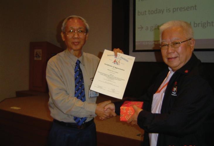
Figure 2: Ir. Mah Soo, Advisor cum Session Chairman of EETD presenting a token of appreciation to Ir. Wong
Figure 1: Ir. Wong and Ir. Mah Soo
talk on Project learning for sustainable innovativeness and Competitive advantage
the talk entitled “Project Learning for Sustainable Innovativeness and Competitive Advantage” was organised by the Project Management Technical Division (PMTD) of IEM on 20 November 2010 at Wisma IEM, Petaling Jaya. The talk was delivered by Sr. Dr Zulkiflee Abdul Samad, who is a Senior Lecturer in Project Management at the Faculty of Built Environment, University of Malaya.
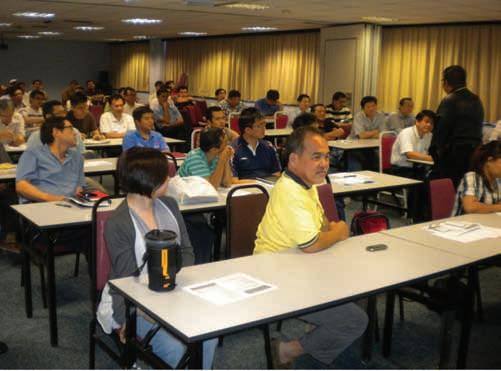
Sr. Dr Zulkiflee is an academician, consultant and professional, with about 15 years of experience in project management in both the construction industry and academia. He is also currently the Head of Department of Quantity Surveying. The session was chaired by Ir. Lee Boon Chong. A total of 63 participants attended the talk. The talk covered the following four main areas.
Knowledge and Knowledge ManageMent CyCle in ProJeCts
Sr. Dr Zulkiflee first described the meaning of explicit knowledge, tacit knowledge and knowledge management. Knowledge management cycle in project is defined in four sequential steps, starting from data collection, processing data into information, transforming actionable information into knowledge and embedding knowledge into individual and organisational processes that add value to projects.
ProJeCt and organisation learning
The speaker then explained that, although projects were extremely suitable for learning due to their time limitation, resource constraints, great complexity, diversity and risk propensity, mistakes might be repeated in new projects and some efforts might be redundant.
by Ir.
Very often, the end of the project means the end of the learning process. The purpose of project learning is centred on project risks, project competencies, sustainable innovativeness and competitive advantage.
Categories of knowledge that can be derived from projects consist of technical knowledge, procedural knowledge and organisational knowledge. By systematically documenting the most effective problem-solving mechanisms and the most serious mistakes that were made in the course of a project, organisations can then reduce project risk, develop project competencies and build up sustainable innovativeness and competitive advantage.
ProJeCt learning - Cultural iMPaCt, Methods, iMPediMents and Key suCCess faCtors
Project learning is described as a set of actions used by the project team to create and share knowledge within and between projects. It consists of operational learning, organisational learning and managerial learning. The speaker described the link between project learning and organisation learning. Cultural impact was then explained in terms of knowledge comparison between an individual and a group, universal and circumstantial, low context and high context, and theoretical and pragmatic.
Three methods of project learning were outlined, namely, human-centred, process-based and content-based. Examples of impediments to project learning are cultural diversity, project nature and communications. Project key success factors were discussed, including institutionalising the lessons learned process, having continuous project review,
Lee Boon Chong
ProJeCt ManageMent teChniCal division
Sr. Dr Zulkiflee sharing his knowledge and experience
Members listening attentively
gaining top management support, encouraging employee participation and using ICT to create knowledge space.
fostering ProJeCt and organisational learning
Sr. Dr Zulkiflee gave an outlook on what an organisation could and should do in order to create an effective learning environment and its potential impact on organisational learning from projects. He wrapped up the presentation by proposing three methods for fostering project and organisational learning, i.e. integrating project learning into project management methodology, establishing knowledge enablers, and moving towards the ideal of a learning organisation. The talk ended with a very active Q&A session. n
Talk on Waterproofing Solutions for Basement and underground structures
the Civil and Structural Engineering Technical Division organised an evening talk on 22 September 2010 on the solutions to waterproofing for basement and underground structures. The talk was conducted by Gordon Sprouse of Fosroc, United Kingdom, and was attended by 60 participants.
Sprouse advised that the design considerations must first be looked into before selecting the appropriate waterproofing system for an underground basement. He informed that, in the UK, there are two documents being used as reference to assist in specifying the most appropriate waterproofing system, i.e. CIRIA Report No. 139 (Water-Resisting Basement) and BS 8102:2009-Protection of Below Ground Structures against Water from the Ground.
The CIRIA report complements BS 8102, which adopted the use of different grades based on the use of the basement. For example:
Sprouse mentioned that there are three main types or methods to provide waterproofing protection to the basement. He explained each of them in detail:
Type A - Tanked ( e.g . membranes and coatings)
Type B - Integral ( e.g . waterproofing admixtures)
Type C - Drained ( e.g . HDPE panels)
He informed that CIRIA Report No. 139 provides a table to guide in the selection of waterproofing system:
The basement use and grades should be agreed upon by the owner(s) and consultant(s) before selecting the appropriate waterproofing system.
Finally, he advised the engineers to look into the detailing of each waterproofing system that had been selected as many waterproofing failures were due to lack of effort in detailing.
Sprouse then presented a case study on a recent project he was involved in and highlighted the uniqueness of the project and the detailing issues for that waterproofing system.
The evening talk ended with a lively discussion. Ir. Boone Lim, the chairman, thanked Sprouse and presented him with a token of appreciation. n
IEM's appreciation to Sr. Dr Zulkiflee
by Ir. Boone Lim
Workshop on “Challenges of Women engineers in the Industries”
by Ir. Sharifah Azlina binti Raja Kamal Pasmah
there is more happiness in sharing than in keeping, and this was certainly the spirit when a workshop on “Challenges of Women Engineers in the Industries” was held at Universiti Kuala Lumpur Malaysian Institute of Chemical and Bio-engineering Technology (UniKL MICET), Alor Gajah, Melaka. The workshop, jointly organised by the Women Engineers Sub-committee, IEM, and the Section of Chemical Engineering Technology (SCET), UniKL MICET, saw a total of three lady engineers’ speakers from the industry. A total of 80 students and 10 lecturers attended the event.
The chemical engineering students – all ladies – and presenters from IEM, were both enthusiastic to impart upon each other the shared knowledge, experience, joy and anxiety of becoming and being an engineer in the industry. UniKL MICET, is located on a sprawling campus at Taboh Naning, Alor Gajah, Melaka, which is a good one-hour’s drive from Kuala Lumpur.
After a welcoming address by Assoc. Prof. Dr Ahmad Marzio Mohd. Yusof, Deputy Dean of UniKL MICET, Ir. Sharifah Azlina Raja Kamal, a highway and transportation engineer, briefly took the audience through the organisational structure of The Institution of Engineers, Malaysia (IEM) and the stance of the Women Engineers Sub-committee . Due to the concern on the decline in the number of women engineers who remained in the profession, which was then less than 12% of the total registered engineers in the nation, this sub-committee was formed with the objective to encourage aspiring female engineering students to practice and remain in the engineering profession throughout their career life.
Next, Ir. Raftah Mahfar, a geotechnical engineer, deliberated on the numerous activities held by this subcommittee since its formation and, in particular, during the recent years in promoting the enthusiasm and inspiration to be a successful lady engineer. This includes giving talks at universities as well as secondary schools to motivate female students to pursue a career in engineering and be part of the nation-building team.
The presenters, at the request of one of the students, also briefly explained the requirements of becoming a professional engineer after graduating. Another key interest amongst the attendees was the challenges faced in striking a balance on both the career and family fronts. Ir. Sharifah Azlina said, “We do not strike a balance. We
attend to both according to their needs and priority given to each. Ir. Raftah added, “And we multi-task, women are natural multi-taskers, and this is how we get a lot if not all things done.”
Ir. Yee Sew Ping, a professional engineer with a chemical engineering background, continued to give an enlightening talk on her early days as a process engineer and her valuable experience since she moved to become a consulting engineer. She touched on the subject of the contribution by a chemical engineer in areas such as oil and gas industries, wastewater and environment, and manufacturing; accentuating the immense demand for chemical engineers in the near future both locally and globally.
This served as a reminder for the tremendous need for chemical engineers to help the country becoming a developed nation. To the concern whether chemical engineering is ‘safe’ especially among women, Ir. Yee emphasised that given the strict regiment of QA or QC and comprehensive procedures which are the norm in a manufacturing environment, “Changing a bulb yourself at home carries more risks than carrying out a similar task in a controlled manufacturing environment”, much to the surprise of the audience.
Keen interest among the students was demonstrated during the Q&A session such as the grave concern if they have made the right choice of career and how to juggle life in this ever-demanding profession. Assurance was given by the presenters that, although it is challenging, it is also one of the more rewarding careers.
Also to the gratitude of IEM, Ir. Dr Chan Tuck Leong, who is the spouse of Ir. Yee, gave an ad-hoc presentation on chemical engineering and the roles of a chemical engineer. Ir. Dr Chan, who practices in an oil and gas organisation, shared the experience of his career path upon graduating and the various opportunities available in related industries. The slides illustrated the options available to the aspiring chemical engineering students. Being the only ‘thorn’ among the 'roses', Ir. Dr Chan affirmed his support for the ladies to pursue engineering as a profession.
After the lunch provided by UniKL MICET, the workshop proceeded with the afternoon session of group work. Each group, consisting of 10 students, was given a topic for deliberation. Their task was to analyse and
Women engIneers sub-CommIttee
explore the subject matter under the supervision of a lecturer in each group. Presentations were made on the findings at the end of the session, and the most creative group walked away with a hamper for their outstanding effort.
The workshop ended with its intended objective achieved. Awareness was raised among the students on the requirements of the engineering profession and challenges that come along with the career. The workshop has also promoted empowerment among the female students to contribute to the development of the nation. As for the female presenters, each left the workshop affirming their commitment to remain steadfast in the profession n
Futsal tournament 2011
IeM-YeS
the IEM-YES Futsal Tournament 2011 was held on 8 January 2011 at Sports Planet Kajang, Bandar Teknologi Kajang. The event was organised by the Uniten Student Members in collaboration with the IEM-YES Committee Members. This event was initially scheduled for last year as part of the IEM-YES activities but was postponed due to technical problems.
The futsal event was open to engineers and engineering students who had a team of eight players. It was considered an international event as, besides the local teams, there were a number of teams consisting of international students from Sudan, Iran and Saudi Arabia.
The tournament had a limit of 40 teams. Some of the sponsors which supported this event included Sentosa Jaya Sdn Bhd, G&P Professionals Sdn Bhd, Stesen Kontraktor Sdn Bhd, Pertanian Pertiwi Sdn Bhd and Sg. Jan Kuari.
The organisers highly appreciated the kindness of these companies which were willing to support the futsal tournament. There were a total of 380 participants including the team managers and supporters for each team. There were also a number of teams from engineering companies such as MMC-Gamuda Bhd, HSS Integrated, Hitachi Integrated and many more who took part in this prestigious futsal event.
The one-day futsal event kicked off at 9.00 a.m. and ended at 5.00 p.m. The competition among the 40 teams was tight. Catalonia FC, the team from UNITEN, managed to grab first place and won the RM3000 cash prize, trophy and medals. The first runner up went to team Dani FC from Malaysia, while the second runner up was team Caspian FC from Iran.
In a nutshell, this futsal tournament provided a unique platform to forge a stronger bond between engineers, students, local futsal players and international participants, as well as to promote a harmonious, understanding and peaceful life together in Malaysia and a healthy lifestyle by getting involved in sports activities. Thank you for the support from all parties to make this event a success for the IEM-YES G&S. n
Figure 1: The IEM-YES Committee Members who supported this event
Figure 2: Faces of some of the international participants
Figure 3: The team from engineering company MMC-Gamuda Bhd
Figure 4: Some of the international participants and supporters
Figure 5: Prize giving ceremony for the champions – Catalonia FC
by Engr. Ganesh Rao
3-Day Course in Practical Design to MS eC0, MS eC1 and MS eC2 from a Consulting engineer’s Perspective
the IEM Civil and Structural Engineering Technical Division organised the above course from 10 to 12 March 2010 at the Armada Hotel, Petaling Jaya. The course leader was Ir. M.C. Hee, a very experienced and prominent consulting structural engineer and also one of the past current Vice Presidents of The Institution of Engineers, Malaysia.
About 100 engineers, including company directors and academicians, attended the course. The course was chaired by Ir. Assoc. Prof. Dr Chiang Luin, Jeffrey and started with an opening remark from the IEM President Ir. Vincent Chen Kim Kieong.
The course started with Ir. Hee highlighting the impact of structural Eurocodes on designers. Among others, he emphasised that engineers need to familiarise themselves with new terminologies, notations and the fact that the code is a performance based code and not a descriptive type as in the BS 8110. Ir. Hee announced to the participants the availability of the newly drafted Malaysian Standards based on Eurocodes for the basis of structural design, actions on structures and design of concrete structures.
He then went on to elaborate the scope of the MS EN1990 EC 0 and touched on the principles of Limit States design philosophy. The new loads and materials safety factors, and how they are used in the Ultimate Limit State and Serviceability Limit State load combinations were illustrated with practical examples.
MS EN1991-1-1 EC 1: Actions on Structures was deliberated after the tea break. The code provides guidance on design actions (or design loads) for the design of buildings and civil engineering works. These include the densities of construction materials, self-weight of construction workers, and equipment and imposed loads for buildings.
The afternoon session was devoted to practical ways of designing reinforced concrete structures in accordance with the MS EN1992-1-1 EC 2: Design of Concrete Structures, using fundamental and innovative methods. These include the use of the two-cycle moment distributions and the designing of reinforced concrete beams using the unified
method, which was first introduced by Prof. Antoine Naaman. The MS EN1992-1-1 effectively supersedes MS1195, which was the Malaysian Standard version of BS8110. Readers may refer to the insert article on the application of the unified method in Eurocode 2.
The second day of the course started with a discussion on the Serviceability Limit States, which include design considerations for durability, fire actions and deflection. Ir. Hee elaborated at length the causes of the loss of durability in practice and related these to the requirements stipulated in the Eurocode. Definitions of concrete cover in the Eurocode and how they are supposed to be used in relation to durability and fire requirements were also elaborated during the course.
Design of shear and torsion for reinforced concrete columns and walls in accordance with the MS EN1992 were the main focus on the second day of the course. Ir. Hee explained the design concept in the new codes, compared them with the BS 8110 and gave practical design examples. The concept of braced column was emphasised during the course. In the example, Ir. Hee suggested, for simplicity sake, the recommendations by the Institution of Structural Engineers may be adopted instead.
Day 3 was devoted to the design of a 10-storey office building in accordance with the Eurocode. The participants were given the opportunity to design a 10-storey office building in Kuala Lumpur, based on Malaysian conditions. The design process was then discussed at length and the participants were given the complete design example of the building at the end of the session.
The course was concluded by the course leader with a discussion on why sometimes we (as the designers) get it wrong. In this session, the participants were warned about the common practical mistakes that could happen during the design process.
In conclusion, the course was very well received by the participants as confirmed by the survey conducted. It also imparted a lot of new knowledge in terms of the use of the Eurocode and, more importantly, the practical aspects in the design of concrete structures.
(To
by Ir. Prof. Dr Mohd. Zamin bin Jumaat and Ir. Assoc. Prof. Dr Chiang Choong Luin, Jeffrey
Civil anD StruCtural engineering teChniCal DiviSion
DeSign ProCeDureS to MS eC0, MS eC1 anD MS eC2 uSing the unifieD MethoD aPProaCh
In general, for designing concrete structures, Equation 6.10 of the code for the Ultimate Limit State Fundamental Combination and Equation 6.14 of the code for the Serviceability Limit State Characteristic Combination can be used. These are reproduced as Equations (1) and (2).
Ed = Σ γ G,j Gk,j + γ p P + γ Q,1 Qk,1 + Σ γ Q,i ( ψ o,i Qk,i) (1)
Ed = Σ Gk,j + P + Qk,1 + Σ ψ o,i Qk,i (2) J≥1 i≥1
where,
γG,j = Partial factor for parmanent action, Gk,j = Characteristics value of permanent action
γp = Partial factor of prestressing action, P = Representative value of a prestressing action,
γQ,i = Partial factor for variable action.
Qk,1 = Characteristics value of the leading variable action,
ψo,i = Factor for combination value of variable cation, Qk,i = Characteristics value of variable action
The Unified Method deliberated by Ir. M.C. Hee was shown to be suitable for use for designing reinforced, partially pre-stressed and pre-stressed concrete flexural members. In this report, usage of the method for the simplest case, i.e. for a singularly reinforced rectangular concrete section, is used to illustrate the method. It is based on the EC2 simplified stress block approach as shown in Figure 1.
From the simplified stress block diagram (Figure 1), d = –––––––––––––––––––––––– (3)
Hence, q is a combined reinforcing index, i.e . a unifying parameter between reinforced, pre-stressed and partially pre-stressed sections.
For moment equation about the hybrid centroid, d, Σ MEd = 0.567 fckb ( γ) k u d ( d - γ k ud/2) + 0.87 fykAs ( d-d' ) = bdfckqd (1-0.5( γ ) k u) + 0.87 fykAs ( d-d' )
For the case of the singularly reinforced rectangular section,
MEd = bd 2fckq ( 1 - 0.5 q /0.567) (7)
q = 0.567 { 1- 1 - (–––––)} (8)
K = –––––– (9)
bd 2fck
0.5 q 0.567
= q (1- –––––) (10)
Equations (8) and (10) are the equations normally used to design and check singularly reinforced rectangular concrete sections.
For setting practical limit, the maximum and minimum values for ‘q’ must be established. These are set as follows, From Equation (4),
q = –––––––––
= 0.567 (0.8) K u (11)
For fck ≤ 50/60, the maximum value for Ku for ductile failure is given by Ku = 0.45. Hence, qmax = 0.567 (0.8) (0.45) = 0.204
From Figure 1, the lever arm,
z = d - 0.8 K u –– (12)
0.87 A sfyk bdfck d 2
The maximum lever arm allowed by the code for practical reasons is z = 0.95 d
From Equation (12), we have, K umin = 0.125.
Substituting this in Equation (11), qmin = 0.057.
Hence the limitation values for ‘q’ allowed by the code is 0.057 < q < 0.204. n
Figure 1: Simplified stress block for reinforced, partially pre-stressed and prestressed concrete
Project Management and Six-Sigma: A New Approach
the Project Management Technical Division (PMTD) of IEM organised a two-hour talk entitled “Project Management and Six-Sigma” on 18 September 2010 at the Auditorium in Wisma IEM, Petaling Jaya. The talk was conducted in collaboration with Genaxis Sdn Bhd, currently the first and only American Society For Quality (ASQ) Certified Partner in Malaysia.
The talk was delivered by Mr. Selveentharan Muniandy, the Chief Operating Officer (COO) of Genaxis. He is a professional member of the American Institute of Industrial Engineers and a Registered Graduate Engineer with the Board of Engineers Malaysia. He holds a Bachelor’s Degree (Hons) in Business Information System and is a Certified ASQ Master Black Belt Instructor, Six-Sigma Black Belt from General Electrics US and Starwood Hotels and Resorts Worldwide Inc. Mr. Selveentharan has previously conducted two other sessions on “Project Management and Six-Sigma" for IEM in 2009.
The primary objective of the talk was to introduce the participants to the use of the combination of tools of Project Management and Six-Sigma, which can play a significant role in the engineering environment. Project Management is a strategy applied in planning, organising and managing projects to ensure the success of completion of project goals and objectives. On the other hand, Six-Sigma is a statistical based process improvement methodology and risk management tool that helps in minimising errors and risk, reducing costs, improving workflow and increasing customer satisfaction.
Six-Sigma, at many organisations, simply means a measure of quality that strives for near perfection. But the statistical implications of a Six-Sigma program go well beyond the qualitative eradication of customer perceptible defects. It is a methodology that is well rooted in mathematics and statistics.
The objective of Six-Sigma Quality is to reduce process output variation so that ±six standard deviations lie between the mean and the nearest specification limit. This will allow no more than 3.4 defect Parts per Million (PPM) opportunities, also known as Defects per Million Opportunities (DPMO), to be produced.
By implementing Six-Sigma wisely on carefully selected projects, companies will benefit from:
• Improved customer satisfaction
• Reduced cycle times
• Increased productivity
• Improved process flow, capacity and output
• Reduction in total defects
• Increased product reliability
• Decreased work-in-process (WIP)
Here is a brief explanation on Six-Sigma Green Belt and Black Belt:
Black Belt (BB)
Black Belts are the heart and soul of the Six-Sigma quality initiative. Their main purpose is to lead quality projects and work full time until they are complete. Black Belts can typically complete four to six projects per year with savings of approximately $230,000 per project. Black Belts also coach Green Belts on their projects, and while the coaching may seem innocuous, it can require a significant amount of time and energy.
Green Belt (GB)
Green Belts are employees trained in Six-Sigma who spend a portion of their time completing projects, but maintain their regular work role and responsibilities. Depending on their workload, they can spend anywhere from 10% to 50% of their time on their project(s). As the Six-Sigma quality program evolves, employees will begin to include the Six-Sigma methodology in their daily activities and it will no longer become a percentage of their time - it will be the way their work is accomplished 100% of the time. This is how some companies have organisationally structured their Six-Sigma quality program. But how can one ensure that everyone is doing their job? How can one keep their employees motivated when fires are burning all over the corporate landscape?
This was the third time IEM had organised this kind of Project Management and Six-Sigma talk. A total of 86 participants from various industries attended the talk. They consisted of both corporate members and graduate members of IEM. At the end of the talk, Mr. Selveentharan received a certificate of attendance and a memento from Ir. Noor Iziddin Abdullah bin Haji Ghazali, who currently serves as a Committee Member of PMTD. Feedback from the talk participants was encouraging with some indicating their intention to go for Six-Sigma Green Belt and Black Belt certification. It is hoped that more engineers will participate in this talk to enhance their professional knowledge as well as professional career. First Admiral (Rtd) Dato’ Ir. Ahmad Murad bin Hj. Omar, who currently serves as the Advisor of PMTD, chaired the talk’s opening while Ir. Noor Iziddin Abdullah bin Hj. Ghazali chaired the closing talk. n
by Ir. Noor Iziddin Abdullah bin Haji Ghazali
ProJect ManaGeMent technical DiviSion
StatCOM Control for Power transmission System Stabilisation
a talk on STATCOM Control for Power Transmission System Stabilisation by Dr Stella Morris was conducted on 10 February 2011. The talk, attended by 30 participants, was organised by the Engineering Education Technical Division.
Electrical energy consumption per year is increasing in tandem with the increase in demand year-on-year. This necessitates new development in efficient electricity system management in the form of combined cycle power stations, renewable energies, green energies, etc . One of the main components in the electrical system is the transmission line. As the development of new transmission lines is increasing, several issues such as limited resources and environmental restrictions have become major stumbling blocks. A promising solution called FACTS (Flexible AC Transmission System) was introduced to overcome these problems.
FACTS is an AC transmission system which consists of static and power electronics based controllers. It focuses mainly on controllability and power transfer capability. The most important element in FACTS is the thyristors – small, high voltage, semiconductor-based devices that permit the control and switching of very high power transmission within milli- or micro-seconds. FACTS devices can be fitted into different applications such as Static VAR Compensator (SVC), Static Synchronous Compensator (STATCOM), Thyristor Controlled Series Capacitor (TCSC) and Unified Power Flow Controller (UPFC).
STATCOM is a shunt controller that injects current and controls the voltage with reactive power compensation, where it supplies almost a constant reactive power. STATCOM is designed with self commutated converter technology, which offers rapid response to system events. STATCOM has the capability to provide reactive power, thus protecting the system from potential threats of voltage collapse.
Dr Morris emphasised on the use of STATCOM in improving the dynamic performance and transient stability of power systems as well as minimising the adverse impacts of power system stabilisers (PSS). She also presented a few simulation results for STATCOM using Neuro Sliding Mode Controller as well as Fuzzy and Artificial Neural Network based controller, for both single and multi machine power systems. The simulation results showed that a system using STATCOM produces good and stable results for every simulation. This shows that the STATCOM controller is a viable solution to address system stability issues for power transmission systems. n
engineering eduCatiOn teChniCal diviSiOn
by Engr. Balamuralithara Balakrishnan
Answer for 1Sudoku published on page 18 of this issue.
Hot-air Ballooning over Cappadocia
CappadoCia is a region measuring about 400km eastwest and 250km north-south in central Anatolia, Turkey. And Turkey, as everyone knows, is the only country other than Russia that spans over two continents, namely, Asia and Europe.
The intercontinental boundary runs from the Black Sea in the north through the Bosphorus Strait to the Sea of Marmara and thence through the Dardanelles to the Aegean Sea in the west. Only about 3% of Turkey’s total land area of 814,578sqkm is in Europe. The rest, i.e . the 97% that is in Asia, is known as Anatolia. Yet Turkey is often considered a European country. It even made an attempt to become a member of the European Union.
The name Cappadocia is an English adulteration of the Turkish name “Kapadokya”, which means “land of wellbred horses”.
Several volcanoes erupted about 30 million years ago, covering the Cappadocia region with ash and mud. These solidified over time to form a soft rock known as tuff. Agents of erosion, i.e . water, wind and temperature variations, then worked through the extremely slow process of carving out the bizarre geological features evident in Cappadocia today – table mountains, straightsided red canyons, slender columns capped with a boulder of basalt, and forests of large conical rocks known as “fairy chimneys”. Centuries of human habitation and activities have resulted in villages of rock-hewn houses and churches in the fairy chimneys as well as underground cities with a vast network of tunnels and chambers.
My wife and I arrived by bus at the village of Goreme located right in the heart of Cappadocia one evening in November last year. We got a double room with en-suite facilities in a fairy chimney of a hotel near the bus station. For the next three days, we used the hotel as our base to explore Cappadocia from the air, by bus, on foot and on motorcycle.
One of the best ways to appreciate the unique geological features of Cappadocia is by floating in the air suspended from a hot-air balloon. Cappadocia is reputedly one of the best places in the world to enjoy the experience of hot-air ballooning. It is not cheap though. A one-hour-plus ride in a basket suspended below a hot-air balloon will set you back by 125 euros.
Our airborne adventure started at 5:30 a.m. when a van from the balloon operator picked us up from our hotel and
by Ir. Chin Mee Poon
took us to an office in an adjacent village. After signing an indemnity form and having a cup of hot coffee with biscuits, we were transferred together with other tourists to the launching pad in a secluded place. Ours was a large balloon and the basket, divided into five compartments with the central one reserved for the captain, took in 24 passengers. We shared a compartment with a couple from Hong Kong and two Japanese girls.
By turning on the gas burner to heat up the air in the balloon as and when required, the captain could control our height above ground, and by pulling one or another of several ropes hanging down from the balloon, he was able to rotate the balloon so that all of us in the basket could take turns to have an unobstructed view of certain features on the ground. However, the captain had no control over the direction and speed at which we were drifting through the air.
For one hour and 10 minutes, we had a most exhilarating and rewarding experience of surveying quite an extensive area of Cappadocia from a bird’s eye-view at different heights. We saw the magic of light play among the fairy chimneys as the morning sun climbed over the distant mountain and cast its golden blanket of light and shadow over the earth. Some 50 balloons of varying colours and sizes were floating at different heights over Cappadocia. What a mesmerising sight!
I do not need a flight certificate to remind me of this experience. The aerial view of so many fairy chimneys and houses, a real-life fairyland, has already been indelibly engraved in my memory. n
development in seismic actions study in malaysia and implications to professional practice in the local construction industry (part 2)
analysis and design approach for seismic actions in Building structures
(a) From a structural engineer’s perspective
The behaviour of building structures to earthquakes is very much dependent on how they are designed. The following will illustrate how and what to do and not to do, from a structural engineer’s viewpoint.
How do earthquakes affect the structural behaviour of buildings? The illustrations in Figures 4, 5 and 6 depict this very clearly.
● As inertia forces accumulate downwards from the top of the building, the columns and walls at the lower storeys experience higher earthquake-induced forces and are, therefore, designed to be stronger than those in the storey above. (See Figure 4).
● Under gravity loads, tension in the beams is at the bottom surface of the beam in the central location and at the top surface at the ends.
● The level of bending moment due to earthquake loading depends on the severity of shaking and can exceed that due to gravity loading. (See Figure 5).
● Thus, under strong earthquake shaking, the beam ends can develop tension on both the top and bottom faces.
● Since concrete cannot carry this tension, steel bars are required on both faces of the beams to resist reversals of bending moment. (See Figure 6).
In terms of structural integrity and flow, the matter of strength hierarchy is an important factor.
● For a building to remain safe during earthquake shaking, columns should be stronger than beams, and foundations should be stronger than columns.
by
● If columns are made weaker, they suffer severe local damage, at the top and bottom of a particular storey.
Conceptual design and planning is the next consideration in resisting earthquakes, especially in determining the size of buildings and their aspect ratios.
● In tall buildings with large weight-to-base size ratio, the horizontal movement of the floors during ground shaking is large. (See Figure 7).
● In short but very long buildings, the damaging effects during earthquake shaking are many. And in buildings with a large plan area, the horizontal seismic forces carried by the columns and walls can be excessive. (See Figure 7).
Ir. Assoc. Prof. Dr Chiang Choong Luin, Jeffrey
This is continuation of Part 1 of the Eurocode Series Paper published in the April 2011 issue of JURUTERA on pages 34 to 38.
(To
Figure 4: Movements in buildings during earthquake
Figure 5: Tensile zones during movement of structures
Figure 6: Earthquake shaking reverses tension and compression in members – reinforcement is required on both faces of members
● Buildings with simple geometry in plan perform well during strong earthquakes. Buildings with re-entrant corners, such as U, V, H and + shaped in plan sustain significant damage. The bad effects of these interior corners in the plan of buildings are avoided by separating the buildings into two parts by using a separation joint at the junction. (See Figure 8).
● Earthquake forces developed at different floor levels in a building need to be brought down along the height to the ground by the shortest path. Any deviation or discontinuity in this load transfer path results in poor performance of the building. Buildings with vertical setbacks cause a sudden jump in earthquake forces at the level of discontinuity. Buildings that have fewer columns or walls in a particular storey or with unusually tall storey tend to damage or collapse, an end result which is initiated in that storey. (See Figure 9).
● Buildings on sloppy ground have unequal height columns along the slope, which causes twisting and damage in shorter columns that hang or float on beams that have discontinuity in load transfer. (See Figure 9).
● Buildings in which RC walls do not go all the way to the ground but stop at upper levels get severely damaged. (See Figure 9).
Adjacency of buildings plays a significant role in minimising the effect of earthquake in damages incurred due to a mutual destructive mode. (See Figure 10).
● When two buildings are close to each other, they may pound on each other during strong shaking.
● When building heights do not match, the roof of the shorter building may pound at the mid-height of the column of the taller one; this can be very dangerous.
Figure 9: Vertical layout of structures in terms of balanced setback, sufficient rigidity and no sudden deviations in load transfer path will ensure higher seismic resistance
Figure 8: Horizontal layout plays a major role in structural behaviour
Figure 10: Pounding can occur between adjoining buildings due to horizontal vibrations of the two buildings
Figure 7: Buildings with one of their overall sizes much larger or much smaller than the other two do not perform well during earthquakes
There are two design approaches that can be considered. The conventional approach in seismic design is stated as follows:
● This design approach depends on providing the building with strength, stiffness and inelastic deformation capacity which are great enough to withstand a given level of earthquake-generated force.
● This can be accomplished by the selection of an appropriate structural configuration and careful detailing of structural members, such as beams and columns, and the connections between them.
Alternatively, the designer can adopt the basic approach:
● This design approach is not to strengthen the building, but to reduce the earthquake generated forces acting upon it.
This can be accomplished by de-coupling the structure from the seismic ground motion in the following manner:
▪ Increase natural period of structures by Base Isolation
▪ Increase damping of system by Energy Dissipation Devices.
▪ Mitigate earthquake effects completely by using Active Control Devices.
It is not necessary to go into further details of this approach.
In terms of the design philosophy for seismic actions, the severity of ground shaking at a given location during an earthquake can be categorised as minor, moderate and strong, whereby minor shaking occurs frequently; moderate shaking occasionally and strong shaking rarely.
For instance, on average, about 800 earthquakes with a magnitude of 5.0 to 5.9 occur in the world annually, while there are about 18 earthquakes with a magnitude range of 7.0 to 7.9.
So, should we design and construct a building to resist that rare earthquake shaking that may come only once in 500 years or even once in 2000 years, even though the life of the building may be 50 or 100 years?
The answer to that philosophical question is as follows:
● Engineers do not attempt to make earthquake proof buildings that will not get damaged even during the rare but strong earthquake; such buildings will be too robust and also too expensive.
● Instead, engineers should make buildings earthquakeresistant; such buildings should resist the effects of ground shaking, although they may get damaged severely but would not collapse during a strong earthquake.
● Thus, the safety of people and contents is assured in earthquake-resistant buildings, thereby, a disaster is averted. This is the major objective of seismic design codes throughout the world.
Further to that, under minor but frequent shaking, the main members of the buildings that carry vertical and horizontal
forces should not be damaged; however, buildings parts that do not carry load may sustain repairable damage.
Under moderate but occasional shaking, the main members may sustain repairable damage, while the other parts that do not carry load may sustain repairable damage.
Under strong but rare shaking, the main members may sustain severe damage, but the building should not collapse.
For an adequate seismic-resistant design structure, the keyword that needs to be addressed is – ductility.
The correct use of ductile reinforcing (i.e. steel) to ensure the ductile performance of reinforced concrete structures, especially at joints and connections, is the mainstay of a good and sound structural design to resist earthquakes.
The correct building components need to be made ductile. The failure of columns can affect the stability of a building, but the failure of a beam causes a localised effect.
Therefore, it is better to make beams be ductile weak links rather than columns. This method of designing reinforced concrete buildings is called the strong-column weak-beam design method.
Lastly, for a structural engineer to carry out a proper seismic analysis and design of structures, it is very important to adopt the correct methodology, depending on the complexity of the structure and its proximity to seismic active zones. Table 1 summarises the methodology that can be used.
(b) From an architect’s perspective
In view of the likelihood of the Technical Committee (TC) in recommending the adoption of Eurocode 8 EN1998-1:2004 Design of structures for earthquake resistance as the basis for MS, the TC has farmed out various study topics on Eurocode 8 to the five working groups. The working group (WG) on non structural components has commenced by concentrating on materials design. But this should not stop the WG on non structural components to expand its scope into building services such as fire fighting, air handling unit, escape and evacuation points, facade design, lighting and air passages,
Figure 11: Design concept of ductile performance under seismic action
Table 1: Elastic/inelastic versus static/dynamic approach in analysis and design static dynamic
Inelastic (nonlinear) analysis Non-linear Static Method (or Capacity Spectrum Method) Non-linear Time History Analysis
features and layout in minimising internal damages due to collapse of furniture and fittings, and so forth.
There are definitely a lot more areas that architects can contribute in ensuring a safe and adequate building design in resisting earthquakes even in a low seismic zone like Malaysia.
conclusion
No doubt, Malaysia is considered a low seismic risk zone, and may or may not require a seismic design standard for its building structures. But the two regional earthquakes in 2004 and 2005 had changed the perspective of both the public view and concern of the structural vulnerability of local buildings and infrastructures during earthquake events, albeit from far distance effect.
From the study undertaken to date, and with inputs from international experts, it may be worthwhile to focus the attention on local near field earthquake, in particular the Bentong Fault, which is reasonably close to the Kuala Lumpur city centre. To that, one may add the earthquakes that occur more frequently in East Malaysia.
The local authorities have also responded positively to the initiative and effort to draft a national standard for seismic design by offering financial support to professional institutions such as the IEM, which is taking the lead, besides the usual research grants usually reserved for public universities.
The behaviour of building structures during earthquakes is very much dependent on how they are designed, and the various do’s and don’t’s have been illustrated, from the viewpoints of a structural engineer and an architect. It is hoped that with the mutual support and input from both practicing professionals, a national standard on seismic design can be drafted which can then be applied by practicing professionals in the local construction industry.
acknowledgement
The author would like to extend his appreciation to members of the IEM Technical Committee (TC) on Earthquake and also to members of the various Working Groups of the TC, who have all contributed to make possible the publication and presentation of this technical paper in its present form. Many thanks also go to agencies and institutions who have agreed to provide financial support to the work undertaken by the TC on Earthquake. n
references:
[1] Balendra T and Li Z, “Seismic Hazard of Singapore and Malaysia”, eJSE International Journal Special Issue, 2008, pp57-63.
[2] BSI, BS EN 1998-1:2004, “Eurocode 8: Design of Structures for Earthquake Resistance”, 230p.
[3] Chiang, J and Hee MC, “Technical Review of JKR’s Handbook on Seismic Design Guidelines for Concrete Buildings in Malaysia”, IEM Jurutera Bulletin No. 3, March 2008, pp 2628.
[4] Lam N, “2-Day Course on Earthquake Resistant Design and Analysis of Buildings and Structures”, The Institution of Engineers, Malaysia Course Notes, 23-24 September 2009, 128p.
[5] Lam N and Wilson J, “Displacement Modelling of Intraplate Earthquakes”, ISET Journal of Earthquake Technology, Paper No. 439, Vol 41 No 1, March 2004, pp 15-52.
[6] Mohd Rosaidi bin Che Abas, “Earthquake Monitoring in Malaysia”, Seismic Risk Seminar, Malaysia, September 2001.
[7] Mustafa Kamal bin Shuib, “The Recent Bukit Tinggi Earthquakes and Their Relationship to Major Geological Structures”, Geological Society Malaysia, Bulletin 55, November 2009, pp 67-72.
[8] Pan TC and Megawati K, “Estimation of Peak Ground Accelerations of the Malay Peninsular Due to Distant Sumatra Earthquakes”, Bulletin of the Seismological Society of America, Vol 92, April 2002, pp1082-1094.
[9] Quek ST and Pang SD, “2-Day Course on Dynamic Analysis and Earthquake Design of Structures”, The Institution of Engineers Malaysia Course Notes, 21-22 April 2009, 156p.
[10] The Institution of Engineers, Malaysia (IEM), IEM Position Document 2005, “Position Paper on Issues Related to Earthquake”, 23p.
appendiX 1
Mercalli Intensity Scale in Depicting Severity of Ground Shaking Due to Earthquake
● Based on damage and observed effects on people, buildings and other objects – quite subjective and varies from place to place.
● Example, two areas (one densely populated, another sparsely populated) may experience same earthquake magnitude – but the densely populated area has higher intensity due to more damage and loss of lives.
● The Modified Mercalli Scale is used to measure 12 levels of increasing intensity.
Richter Scale in Measuring Earthquake Magnitude
● Measured directly at source, using seismograms and the Richter magnitude M – which is determined from a logarithm of amplitude recorded by a seismometer as:
▪ M = log10(A/A0)
▪ where A0 is a constant equal to 0.001mm
▪ Note that each whole no increase in M represents a 10fold increase in measured amplitude
Richter Scale in Measuring Earthquake Magnitude
● P1 = probability that ground motions of a given intensity will be exceeded in any given year
● Return period = inverse of P1, normally, a 500-year return period for seismic resistant design is very common.
● Example: A building is designed for y = 50-year occupancy has T = 475 years, using formula
To All Members,
Date: 11 April 2011
CaNDIDateS aPPrOVeD tO SIt FOr Year 2011 PrOFeSSIONaL INterVIeW
The following candidates have been approved to sit for the Professional Interview for 2011. In accordance with Bylaws 3.9, the undermentioned names are published as having applied for membership of the Institution, subject to passing the year 2011 Professional Interview.
If any Corporate Member of the Institution has any reason as to why any of the candidates is not a fit and proper person for election, he should communicate in writing to the Hon. Secretary. Such communication should be lodged a month from the date of publication.
Thank you.
Ir. Prof. Dr Lee Teang Shui Honorary Secretary, The Institution of Engineers, Malaysia
NeW aPPLICaNtS
Name Qualifications
CHeMICaL eNGINeerING
JOFRY BIN OTHMAN BE HONS (LOUGHBOROUGH) (CHEMICAL, 1996)
RIZAL AZIZI BIN GHAZALI BE HONS (UTM) (CHEMICAL, 1997)
SITI ZUBAIDAH BINTI SULAIMAN BE HONS (UPM) (CHEMICAL, 2001)
CIVIL eNGINeerING
AMALLUDIN BIN ZOLKIFLI BE HONS (UTM) (CIVIL, 2004)
BAZLI BIN MAT AKHIR BE HONS (USM) (CIVIL, 1997)
LIM BOON CHIANG BE HONS (USM) (CIVIL, 2005)
LIM CHUN HONG BE HONS (UTM) (CIVIL, 2006)
MUHAMAD SAFWAN BIN BE HONS (UiTM) (CIVIL, 2006)
PUTEH @ SHAARI
NEO KIM KIAT BSc (ARKANSAS) (CIVIL, 1998)
SAHRI BIN ALI BE HONS (UPM) (CIVIL, 2000)
TAJUDIN BIN YATIM BE HONS (UTM) (CIVIL, 2002)
TURAHIM BIN ABD. HAMID ADV DIP (UiTM) (CIVIL, 1985)
WONG WENG YIK BE HONS (UTM) (CIVIL, 2003)
ZAIMIN BIN HJ. ABDULLAH BE HONS (UTM) (CIVIL, 2004)
eLeCtrICaL eNGINeerING
ANWAR BIN ISMAIL BE HONS (UNITED) (ELECTRICAL POWER, 2003)
SAIRUL AZALI BIN ZAKARIA BE HONS (UTM) (ELECTRICAL-TELECOMMUNICATION, 2005)
INStruMeNtatION aND CONtrOL eNGINeerING ANG TEOH ONG BE HONS (UKM) (ELECTRICAL, ELECTRONIC & SYSTEMS, 1995)
MeCHaNICaL eNGINeerING
MOHD FZMIZAL BIN ISHAK BE HONS (UKM) (MECHANICAL, 2004)
SUKHAIRUL NIZAM BIN ABDUL RAZAK BE HONS (UTM) (AERONAUTICS, 1995)
VIMALJEET SINGH MALHI BE HONS (UM) (MECHANICAL, 2002)
traNSFer aPPLICaNtS
Mem No. Name Qualifications
CIVIL eNGINeerING
28813 CHAN ZE HONG BE HONS (UTM) (CIVIL, 2006)
26614 EZUAN BIN JAMADON BE HONS (UTM) (CIVIL, 2006)
33981 JEREMY LIM WEI BE HONS (UTM) (CIVIL, 2006)
44174 KUGANESWARAN A/L NADARASA BE HONS (UTM) (CIVIL, 2006)
29220 MOHD KHAIRIL BIN RAHMAN BE HONS (UiTM) (CIVIL, 2006)
IeM DIarY OF eVeNtS
Kindly note that the scheduled events below are subject to change. Please visit the IEM website at www.MyIEM.org.my for more information on the upcoming events.
Sub-committee on Women Engineering
17 june 2011
Ta L k on "P L an your LI fe, L I ve your Drea MS"
Time: 5.30 p.m. to 7.30 p.m.
Venue: TUS Lecture Room, 2nd Floor, Wisma IEM
Speaker: Ms. Joyce Lim (Invitation to register)
30 june 2011
Talk on "S.W.o.T. - Th E Way For P E r S onal a nd
fI nan CI a L g row T h"
Time: 5.30 p.m. to 7.30 p.m.
Venue: TUS Lecture Room, 2nd Floor, Wisma IEM
Speaker: Ms. Joyce Lim (Invitation to register)
16 july 2011
o ne Day w ork S ho P on "Profe SSI ona L
PhoTogra P hy"
Time: 9.00 a.m. to 5.00 p.m.
Venue: TUS Lecture Room, 2nd Floor, Wisma IEM
Speaker: Mr. Tey Hwee Wai
Fees: IEM Member-RM250.00 Non-IEM Member-RM350.00 (Invitation to register)
16 july 2011
o ne Day work S ho P on re S our C efu L now:
Tran S for M T he vI Pe r wIT h I n
Time: 9.00 a.m. to 5.00 p.m.
Venue: C&S Lecture Room, 2nd Floor, Wisma IEM
Speaker: Mr. Tey Hwee Wai
Fees: IEM Student and Graduate Member-RM200.00 IEM Member-RM300.00
Non-IEM Member-RM370.00 (Invitation to register)
I e M Major e ven TS
12-14 july 2011 b rownf I e LD aSI a 2011
International Conference on Remediation and Management of Contaminated Land: Focus on Asia
(Call for paper)
Venue: Sunway Resort Hotel and Spa, Selangor Fees: IEM Student Member-RM400.00
IEM Member-RM800.00
Non-IEM Member-RM1,500.00
Overseas Participants-RM1,500.00 (Invitation to register)
20318 LEE LEH SING BE HONS (BIRMINGHAM) (ELECTRONIC & ELECTRICAL, 1999) 39993 LIM LEE CHENG BE HONS (UNITEN) (ELECTRICAL POWER, 2007) 26875 MOHD SHARIZAL BIN BE HONS (LIVERPOOL) ABDUL ALIBU (ELECTRICAL & ELECTRONIC, 2004)
eLeCtrONIC eNGINeerING
22836 MEGAT MOHD ADZRUL NAAIM BE HONS (UiTM) (ELECTRICAL, 2004) BIN MEGAT KHAMARUDDIN 16879 RIZALUDIN BIN KASPIN BE HONS (VICTORIA UNI OF MANCHESTER) (ELECTRICAL & ELECTRONIC, 1992)
INStruMeNtatION aND CONtrOL eNGINeerING 26899 MOHD REDZUAN BIN BE HONS (UTM) (ELECTRICAL, 2003) MOHD RAFIEE 41332 MUAMMAR GADAFI HAIRUDIN BSc (LEHIGH UNI, BETHLEHEM, USA) (ELECTRICAL, 1997)
CONF ere NC eS & S e MIN arS a nnoun C e M en T
For more information, kindly contact the organiser accordingly.
6-7 october 2011
InTernaTIonaL ConferenCe on geoTeChnICS for SuSTaInabLe DeveLoPMenT
Venue: Hanoi, Vietnam
Tel: (84-4)6.269.0481/82
Fax: (84-4)6.269.0484
Email: secretariat@geotechn2011.vn
Website: www.geotechn2011.vn (Call for register)
27-30 november 2011
29Th ConferenCe of aSean feDeraTIon of engIneerIng organISaTIonS on SuSTaInabLe urbanISaTIon: engIneerIng ChaLLengeS anD oPPorTuniTiES (CaFEo 29)
Venue: The Rizqun International Hotel, Bandar Seri Begawan, Brunei
Tel: +673 238 4021
Fax: +673 238 4021
Email: cafeo29.brunei@gmail.com
Website: www.puja-brunei.org (Call for register)
DONatION LISt tO tHe WISMa IeM buILDING FuND
The Institution would like to thank all contributors for donating towards the Wisma IEM Building Fund. Members and readers who wish to donate can do so by downloading the form from the IEM website at http://www.MyIEM.org my or contact the IEM Secretariat at +603-7968 4001/4025 for more information. The list of the contributors as at 31 March 2011 are shown as in table below.
1
2
3
Make It Safe
thIS month, we will look at Part 5 of the Occupational Safety and Health Act 1994 on the General Duties of Designers, Manufacturers and Suppliers for:
1) Section 20: Plant for use at work; and 2) Section 21: Substances for use at work.
In Section 20, the plant (e.g. machinery, equipment, appliance, tool and its attachments) needs to be: 1) designed, 2) constructed, and 3) tested (examined)
to ensure that it is safe when used properly. This entails conducting proper research and providing proper instructions on its safe use to the client.
In Section 21, the focus is on substances (both natural and artificial) for use at work, and we commonly refer to these as chemicals. The substance can be formulated, manufactured, imported or supplied. The substance should be safe when properly used, handled, processed, stored or transported. The duties cover conducting proper
CONDOLeNCeS
We regret to inform that engr. Chang Wei Chung (G 24982) and Ir. Chan Weng Chiu (F 00209) had passed away on 15 December 2010 and 16 February 2011 respectively. On behalf of the IEM Council and management, we wish to convey our deepest condolence to their family members and would like to acknowledge their past support and contribution to the Institution.
by Ir. Shum Keng Yan
research, testing and providing sufficient information (mainly through Material Safety Data Sheets or Chemical Safety Data Sheets).
As you can see, this group brings in new “items” into the process. They have a special role in ensuring that the plant and substances can be used properly without risk to safety and health.
In summary, we have looked at the key accountabilities, roles and responsibilities of Employers, Employees, Contractors and Designers/ Manufacturers/Suppliers.
Share your design safety experience with us at pub@ iem.org.my n
My favourite part of the Material Safety Data Sheet is a common phrase in Section 13: Disposal Considerations: “Dispose in accordance with appropriate Federal, State and local regulations.” I suppose it is common sense for the layman to know the Federal, State and local regulations!
errata
Amendments to Q2 of Section B Essay (1.1.2011) for the Professional Interview.
Questions on regulations on Professional Conduct
2) You are assigned by your employer to prospect an area for an extractable material. However, in the course of your work, you discover no such object material but some other valuable material which your employer is not interested. On the other hand, the information which you have is of great importance to the adjoining interest. As an engineer, can you release the particular information which you have to the other party so that the other valuable material may be explored? Please discuss taking into consideration provisions of the IEM Regulations on Professional Conduct.