


patrick@dimensionpublishing.com
shirley@dimensionpublishing.com
sue@dimensionpublishing.com
siewli@dimensionpublishing.com
art@dimensionpublishing.com
alicia@dimensionpublishing.com
masaki@dimensionpublishing.com
accs@dimensionpublishing.com
DIMENSION
HOFFSET


YANG
TIMBALAN

SETIAUSAHA KEHORMAT / HONORARY SECRETARY:
BENDAHARI KEHORMAT / HONORARY TREASURER:
WAKIL AWAM / CIVIL REPRESENTATIVE: WAKIL MEKANIKAL / MECHANICAL REPRESENTATIVE:
WAKIL ELEKTRIK / ELECTRICAL REPRESENTATIVE:
WAKIL STRUKTUR / STRUCTURAL REPRESENTATIVE:
WAKIL
YANG DIPERTUA / PAST PRESIDENTS:
PENGERUSI CAWANGAN / BRANCH CHAIRMAN:
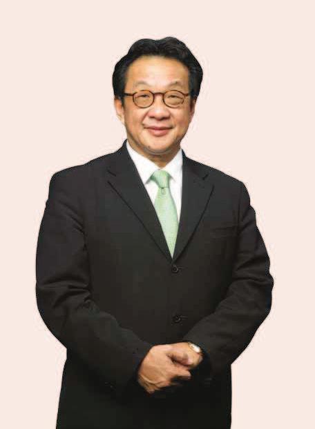
WHEN it comes to home grown successful people who have made their mark internationally, the one name that most often comes to mind is none other than Y.Bhg. Tan Sri Dato’ Engr. Dr Francis Yeoh Sock Ping, Managing Director of YTL Group of Companies. The latter took over the running of YTL in 1988 and nurtured it into a global conglomerate with a combined market capitalisation of over RM30.9 billion and assets of over RM45 billion as of 31 August 2011.
In a recent interview with JURUTERA, the civil engineer attributed the group’s tremendous growth and success to for engineering is God-given. I believe whole-heartedly that engineering is a noble and necessary profession.As such, I feel very strongly that every engineer in the country should commit their skills to make a difference to their community, as well as build something beautiful and everlasting.”
profession and provided some tips for young engineers. Y.Bhg. Tan Sri Dr Yeoh stressed that it is very important for the young to be business savvy and to have a
can learn from. Good mentors can provide guidance on technical and professional issues as well as help one in learning to deal with business challenges and avoid the common pitfalls.
similar to running a business. My engineering training has often helped me make a value judgement based on the available facts and avoid unnecessary speculation and the emotional complexities that come with decision-making.”
Many have wondered if he has ever relied on his ‘gut-feeling’
very much over rated. Everyday, I have to make numerous strategic decisions that will affect my company’s business direction.
Thus, I would rather rely on what I see with my own eyes than something that is intangible.”
BUILDING A SOLID FOUNDATION
Not surprisingly, many have gone to him for advice on how they can replicate his success both locally and overseas.
establishing themselves overseas, local engineers should use their engineering skills and contribute towards the
ensure that they have established a strong foundation in
proud of what they can achieve in Malaysia. For instance, he stated that local engineers were responsible for the major pouring of the Kuala Lumpur Convention Centre and KL Tower. In fact, the concrete shaft of the KL Tower, which stands at 360m,


Do not compromise on your principles and ethics no matter how tempting it is. More importantly, strive to contribute to engineering achievements in your own country.”
inventions help transform human lives for the better.
engineering innovations and inventions, a subject that many young engineers do not take seriously enough and at their loss. Indeed, what good are ground breaking engineering technologies and innovations if they hardly make it to the
The esteemed businessman and engineer also pointed out the complex correlation between engineering and entrepreneurship, arguing that they are intertwined but are by no means easy bedfellows. Contending that engineering carries its true worth only if it could be capitalised upon to help transform and better societies and individuals, the acid test he applies for all engineering is practical application, commercial viability and long-term sustainability.
ground breaking technologies and innovations in history failed to see the light of day, because the engineers who invented them were not entrepreneurial or business opportunity to make a difference.”
Y.Bhg. Tan Sri Dr Yeoh stated that he has always insisted on championing YTL as a force for good, i.e. for advocating environmental conservation and clean become more aware of how urgent it has become for them to deal with pollution and environmental issues, not just for themselves, but also for future generations. Thus, instead of
creating technologies that will pollute, he hopes to see more engineers, both young and old, use their engineering skills to change the world and save the environment.
According to him, the challenge of developing sustainable energy is perhaps one of the most important goals for engineers today. Thus he would like to see
carries its true worth only if it could be capitalised upon to help transform and better societies and individuals. There is no point in creating a destructive technology that eventually that will respect the environment and treasure human life.”
TAKING THE LEAP OF FAITH
Local companies which are ready to make the leap into the global business arena should prepare themselves for the challenges that follow. Y.Bhg. Tan Sri Dr Yeoh pointed out that are doing well in India and the Middle East, especially Abu Dhabi. The advice he gave was that they must be prepared to continuously improve their engineering skillsets
The fastest way for local companies to create an
longer an option to ignore. In fact, the Internet itself is a sign of the next evolution in business communication. It has cut down a tremendous amount of unnecessary paperwork and expedited the speed of business transactions.”
According to him, businesses must establish their online presence and capitalise on what the digital economy has technology to date, that all engineers must capitalise on the Internet and mobile internet technology to advance their engineering businesses.
a global perspective, while Malaysia has been affected here remains resilient. Despite many naysayers claiming otherwise, I believe that there are still many developments in the country that we can look forward to including infrastructure projects such as roads, housing and public transportation.”
engineers in Malaysia who are both capable and excel in their line of work. In Europe as well as South Africa, the demand for engineering skillsets is very high. This is a good opportunity for Malaysian engineers to prove that they are just as good as their foreign counterparts. In fact, those who are in great demand overseas.”


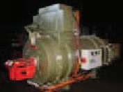
Variable Speed Drive: Is It a Black Box that Saves Electric Energy?

IN Malaysia, at least 80% of the motor systems use induction motors as they are prone to less maintenance problems compared to DC motors. A report in 2010 by the Energy Commission of Malaysia stated that Tenaga Nasional supplied approximately 40,071GWhr (or about 44% of the total 89,621GWhr) of electric energy to the industrial sectors. In any industry, motor systems consume about 60% to 70% of the total amount of electric energy.
That is why the variable speed drive (VSD) system has been introduced to replace electromechanical starters such as direct online (DOL), star-delta and autotransformer to achieve better control and save electric energy. Electric motors controlled using electromechanical starters are very torque (or mechanical power). In addition, motor systems controlled by electromechanical starters do not have operation.
The performance of a motor system is, to a large extent, dependent on the load that determines the torque required to run the shaft of the motor at the expected speed. Mechanical power generated by a motor is simply the product of torque and speed. Hence, unless we control one or both of the parameters, we will not see any savings in electric energy.
Electric energy is a product of electric power (which is the sum of mechanical power and losses) and the duration of operation (see Equation 1)
where eW = electric energy (kWhr), mT = motor torque (Nm), = mechanical speed (rad/sec), lP = losses (W) and t = duration of operation (hr).
Let us take an example of a pump system running with a DOLstarterwherefullvoltagewiththeratedfrequency,50Hz source, is applied to the pump motor when the contactor is energised. If the pump drives an 80% load at all times and the system does not require any change in pressure, then far as electric energy is concerned.
On the other hand, if the pump system runs for many hours at variable or light load with an equivalent load torque of less than 70%, and the system requires changes in
pressure which is currently achieved with the help of valve arrangement, the installation of VSD for the system will possible since VSD applies the required voltage to produce the required torque which reduces iron losses in the motor. Secondly, VSD controls the pressure by varying the motor speed (by changing the supply frequency). Thus mechanical valves are not required, minimising mechanical losses. Thirdly, since speed and torque are controlled, the mechanical power consumed by the motor is the actual power required by the pump system. As such, the same work can be done using the VSD system with lesser mechanical power and losses. This in turn consumes lesser electric energy.
However, it is not a rule of thumb that changing to a VSD system will guarantee electric energy saving. You may end up prolonging your payback period. Surprisingly, they mostly run at 60% or lesser load at all times. This is because the motor is usually oversized to overcome temperature and overloading problems. If this is true, by default, the installation of VSD will allow the motor system to use lesser electric energy to do the same job.
There are many manufacturers producing various brands of VSD, and although each manufacturer boasts of different types of features and performances, the same
source by using an arrangement of diodes and/or insulated gate bipolar transistors (IGBTs). The DC source is then smoothened by a group of capacitors. The smoothened DC source is then converted into a variable voltage, variable frequency AC source using the arrangement of IGBTs.
In general, we can categorise problems associated are problems created due to the nature of the operation of the VSD system itself. For example, current harmonics are time charging DC current produces spike shaped input AC current which contains harmonics. Some other problems in this category include thermal issues on the VSD and motor, bearing current.
Fortunately, most manufacturers have incorporated solutions or can provide proper solutions to minimise these problems. Problems in the second category are more severe and are created by the operators themselves.
(Continued on page 12)


(162039-U)
HYDROCON ENTERPRISE SDN. BHD. NO.8, JALAN MERANTI JAYA 16, TAMAN PERINDUSTRIAN MERANTI JAYA, 47100 PUCHONG, SELANGOR DARUL EHSAN. E-mail : donnyhiew@gmail.com / donnyhiew@hydrocon.com.my
Usually these problems are created when improper parameters are set in the VSD. Improper parameter setting usually happens due to a lack of knowledge on how the VSD works that is when the VSD is assumed to be a black box.
IMPROPER PARAMETER SETTINGS
It is important for any motor system operator to understand that the motor is a mechanical system. Starting with a DOL starter gives a completely different impact on the motor compared to when a VSD system is used to operate the same motor. As explained earlier, the VSD is a high power electronic system or simply an electronic system capable of controlling both high current and high voltage at frequencies in the kilohertz range.
Every setting that one makes on the VSD directly impacts the motor. For example, the VSD can be set to produce an output voltage with a frequency of 200Hz. Can you imagine what will happen to a 4-pole induction motor with a rated speed of 1,470rpm (for 50Hz source) when such a high frequency source is given? The following are several examples of impacts on the motor system when the
Acceleration and deceleration time are two common parameters set at least by every VSD user. Unfortunately, the VSD can simply trip and indicate either over current or short circuit faults whenever the motor starts (upon improper acceleration time setting) and whenever the motor stops (upon improper deceleration time setting). This can be explained based on the motor dynamic equation (see Equation 2)
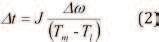
Where t = acceleration/deceleration time (sec.), J = moment of inertia (kgm2), = speed change (rad/sec), T = motor torque (Nm), T = load torque (Nm).
The acceleration or deceleration time is a function of the motor system’s moment of inertia, speed variation and how much motor torque there is compared to the required load torque.
Setting very short acceleration time for a high load torque system [when (Tm -T ) is small] will force the motor to draw a high current which the VSD recognises as over current. In contrast, setting a very long acceleration time for the same system may also trigger the overload alarm as the VSD senses high current being drawn for a longer period of time. Hence, an appropriate acceleration and deceleration time has to be determined by conducting several tests on each motor system by monitoring the starting current every time the motor starts and stops.
Another simple yet serious issue in the industry is the tripping of the VSD due to high temperature. High power semiconductor switches operating at a high
frequency produce a much larger amount of heat than a microprocessor in your laptop. So, placing the VSD at a poorly ventilated and hot environment will trigger the heat sink temperature sensor which trips the VSD. This point is important especially when the system is upgraded from electromechanical starters to the VSD. The motor control environment.
Heating may be also generated due to pulsation current waveforms at the motor. Pulse width modulated (PWM) based generated voltage produces pulsation phase current to the motor which produces a higher ripple in torque and causes mechanical jerking. To smoothen the current, operators are usually advised to increase the switching frequency setting in the VSD which typically can be varied from 4kHz to 20kHz. However, setting a higher switching frequency increases heat across the power semiconductors and heat sink, which can cause the VSD to trip.
There are many more parameters that are incorporated into the VSD, and any improper setting of those parameters will negatively impact on the motor system.
CONCLUSION AND RECOMMENDATION
The VSD may be assumed to be a black box, but when problems associated with the motor system appear, engineers will be left with no choice but to understand the black box. The VSD does wonders for process optimisation and energy savings that electromechanical starters cannot do. However, it is extremely important to know that those wonders are not achieved by simply replacing the electromechanical starter with the VSD. If you operate without understanding the black box, you may mess up the whole motor system.
It is timely to introduce the VSD system with hands-on training at skill-based training institutions. Also, a skilled workforce must be equipped with enough knowledge to face new issues and challenges when dealing with the VSD system. Universities are more focused on the control technologies for the VSD such as vector control and direct torque control. Students should be introduced to the practical problems associated with the VSD system in industry. They should also be exposed to some practical work to understand the importance of the VSD compared to electromechanical starters.As for practising engineers, it is important to understand the VSD system before handling it. Participating in job training and reviewing manufacturer manuals may be a good move at this point of time.
NOTICE
Current and past issues of JURUTERA, the monthly Bulletin of IEM, may now be downloaded from the IEM web portal at www. myiem.org.my
The IEM Editorial Board
YEAFEO, represents the Young Engineers of the national engineering organizations under the umbrella of the Asean Federation of Engineering Organization (AFEO), comprising members engaged in the common professional pursuit of engineering, and aware of the important role of engineering to the advancement of the social, economic and industrial development of the ASEAN region. YEAFEO’s mission is to be a dynamic and progressive organization that leads to the developmentofyoungengineersintheASEANregion.YEAFEO meets every year in conjunction with CAFEO. The last meeting was held in Bandar Seri Begawan, Brunei Darussalam from 27 November to 1 December 2011. This interview was conducted prior to the YEAFEO meeting and illustrates the diversity of opinions held by the representatives.
Q2:
Q3:

Q1.
Q2.
a.
b.
Q3.
Q4. To go beyond education in the dream of becoming attempt projects deemed to be particularly challenging.

Mr. Khin Maung Win – Myanmar Engineering Society (Central Executive Member Joint Treasurer / Chairman of Young Engineers)
Q1. IamKhinMaungWin,jointtreasurerofMESandChairman of the Young Engineers Committee.
Q2. Our young engineers require practical knowledge relevant courses, organise long and short excursions and let them do which are our MES corporate member companies (CMC).
Q3. There is a need to provide more job opportunities, and to support technical development of young engineers. There is also a need to facilitate networking in the ASEAN region and
Q4. Our young engineers should aspire to become capable

Mr. Nazri Tuah – Pertubuhan Ukur, Jurutera dan Arkitek (PUJA), Brunei Darussalam (Chairman of Young Engineers)
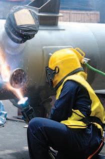
Q1. I am a Mechanical Engineer by training. I work as a Senior Welding and Materials Engineer in the oil and gas ndustry. I am the current Chairman of PUJAYoung Engineers.
Q2. YES are important assets to their home countries and play a vital role in the development of the nation. Dedicated programmes have been set up for YES members to be mentored or coached by senior engineers and leaders so they can one day lead the nation. YESarealsolookeduponaspioneersofnewtechnologies. They are always the ones expected to introduce new technologies into the country. YES are given important roles in projects to give them the exposure and experience that they need early on in their careers. YES are also expected to give guidance and motivation to students to take up engineering as a career especially as Brunei is undergoing rapid development.
Q3. The challenges include looking after ageing facilities together with developing newer facilities in a country that relies heavily on supply of materials from outside the country. There is also the drive to ‘Green Engineering’ as well as ensuring sustainability of any proposed development. Brunei also faces the challenges of lack of resources where there are yet to be enough engineers within the country as compared to other countries inASEAN.
Q4. My hope is for ASEAN YES (YEAFEO) to one day have a strongervoicethanwedonowsowecanmakeabiggerimpact to not just our own country’s development but to ASEAN as a whole. Having more frequent progress meetings will be better than the current practice of meeting only during the mid-term and at CAFEO itself.


of
Q1. Hi! I am Naoyuki Ogawa. Please call me “Yuki”. I have
3 sons, so I have to work to make money now rather than in the future. It’s hard, very hard. I have been working as a civil engineer for 12 years. Compared with when I was a young recruit to now, my interest in my job has increased steadily. Engineering is still developing, and I am also developing myself. My role in IPEJ is a member.
Q2. There was a disaster in Japan this year, but I think it was equivalent to a catastrophe. Now that Japan has recovered engineers in other countries, relate their experiences in giving that extra bit to help the country and the community in critical times.
Q3. novel solutions to overcome technical issues. In Japan, many retired engineers have brought about so much great technology. Young engineers should be aware of this and further exploit the technology from other angles of usage. Also, I think the important factor is to produce novel technology and not to worry about failure. ASEAN is lucky, because the advanced nations have gone through many technical failures. To ensure sustainable and successful development, the young engineers in ASEAN should acknowledge and learn from previous errors.
Q4. I think young engineers should develop themselves not only by using new technology but also learn from former technology which may have better attributes. The Japanese phrase “onko chishin” means that one should learn lessons from the past.

Ms. PRAK Chhay Rotana – Board of Engineering Cambodia
Q1. I am Rotana. My main focus of work is to assist in the registration of engineers in my country and on promoting the role of BEC. Furthermore, I am in charge of international relations during the CAFEO event.
Q2. Young engineers should contribute to the advancement of society and be the role model for the younger generation.
Q3. (No response)
Q4. Young engineers should be the initiators of development within the ASEAN region and the world.

Engr. Shuhairy bin Norhisham – The Institution of Engineers, Malaysia (Chairman of Young Engineers Section)
Q1. My name is Shuhairy Norhisham. Currently, I am Chairman of Young Engineers Section of The Institution of Engineers, Malaysia.
Q2. During the last Young Engineers ASEAN Federation of Engineering Organizations (YEAFEO) meeting, one of the delegates from Brunei had observed, “There are no senior engineers, where there are young engineers”. A simple but a meaningful statement. Everybody agrees on the importance of young engineers in their organisations. In Malaysia, we see young engineers being an important part of the organisations they work in. Some of them are assigned with a group of professionals to be groomed and guided by professional engineers. In other instances, young engineers have even been assigned to take the role of heads of projects. As senior engineers have faith in our universities producing good engineers, most young engineers are given the opportunity to take meaningful roles in projects.
Q3. The challenges that young engineers face today will be different from those in the future. The competitive environment today has encouraged our young engineers to develop their leadership skills. With the rise of new challenges and focus areas such as green technology and even nuclear energy, there will clearly be a need for a different style of management in engineering. With the globalisation of engineers in ASEAN, we shall rise to meet these challenges.
Q4. My dream is for young engineers in ASEAN to come together to think and act as a group to meet the future challenges of globalisation in the engineering sector. respective countries and be able to advise and comment on engineering related issues. Ultimately the voice ofASEAN’s young engineers should be heard throughout the region

- We specialize in design and build with CIDB, Category G7.
- Creative & its collaborative partners are registered with CIDB for on-site & off-site manufacturing of precast component.
RISP programme on selected tender basis.
- We handle both IBS open system and (Simplified Precast Building System).


IN live sound, power interference elimination has become very important as it affects equipment performance. As such, incorporating Electro-magnetic Compatibility (EMC) in Professional Audio-Visual (A/V) system facilities design is a must.
Most of the equipment available today still have very poor immunity to Electro-magnetic Interference (EMI) and related problems; thus it is vital to know what is happening and where to look for problems.
When the equipment or system is closer than about a sixth of a wavelength from the radiation source, it is said to
dominates, and each requires a different kind of treatment to eliminate interference. For example, the twisting of signal
together and are collectively called a wave. Most audio “radio” frequencies; hence the use of the older term RFI (radio-frequency interference). Generally, the newer term EMI also refers exclusively to RFI.
This paper intends to provide a broad outline of some of the practical issues related to ‘clean earth’ or ‘technical earth’ and ‘electrical ground noise’. EMC covers a broad spectrum of electrical engineering issues, including: Electro-magnetic Interference (EMI) Radio-frequency Interference (RFI) Grounding and Bonding, Power Quality.
EMC is the ability of an equipment or system to function satisfactorily without introducing electro-magnetic disturbances to the environment. Professional A/V equipment normally has a ‘CE’ mark. This is essential as it is a statement of conformance by the manufacturer, that the product has been designed and tested to meet the EMC requirements in terms of immunity and electrical emissions.
CHALLENGES FACED BY DESIGNERS
In live sound, the design of an electrical power supply and a good grounding system is very crucial and important. There are many sources of power interference problems

caused by computerised control stage lighting system, stage hoist motor machinery, stage rigging and projector lift. In the design integration of anA/V facilities environment, all these components have the ability to produce a high level of frequency interference with a very wide bandwidth. Processor-controlled circuits are widely used around audio systems. All cables in the systems tend to act as antennas; as such, any interference generated can be distributed to the rest of the system.
As the equipment communications are based on a mix of balanced and unbalanced signalling, it is imperative that resistive or conducted coupling, inductive and capacitive in the case of audio, video feed cables using unbalanced signalling.
A facility such as this would use many single-phase amount of harmonic distortion, including triple harmonics. A triple harmonics, a power quality issue, can cause phase current), which would in turn cause cable voltage drops over the long run, along with the associated elevated temperatures. Besides the harmonics generated by the equipment, lighting dimmers is also another source of harmonics that can be a potential source of EMI.
The next challenge is the ‘clean’ grounding system; electrical ground noise which could cause further EMI to the equipment. An engineering facet in A/V facilities design that at the design from an EMC perspective, one can clearly see that there are other challenges that need to be addressed.
Some of the issues, which will have to be addressed, are described here:
TECHNICAL GROUND SYSTEMS – AVOIDING GROUND LOOPS
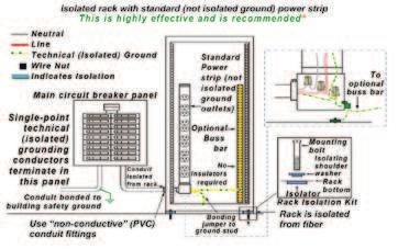
The term ‘technical ground’ or ‘clean earth’ is a network of grounding of the grounding network do not see any potential difference. Avoiding ground loops will minimise noise in audio and video system installations. In a system interconnection for A/V infrastructure, the shields of cables carrying audio frequency signals should not carry current. A noise known as ground loop.
An equipment that is connected to an “isolated ground” system is still grounded, but the bonding point of the ground connection is only at the main conductor must be insulated. It may be spliced when passing through subpanels or junction boxes, but must not be terminated in them.
Since the isolated grounding conductor does not make contact with the this ground circuit is greatly reduced.
“noise-free” signal path. Signal path noise vulnerability depends on whether the interface is balanced or unbalanced. The design and installation of the signal path must include noise interference rejection schemes and effective grounding. Other important aspects of ground systems are discussed below.
Proper grounding reduces only one source of noise. Best practices of good signal path design include good cable management (keeping signal cables more than 2” away from AC wires when running parallel) and twisting signal conductors. It is permissible to strap signal cables to power cables if the conductors of both cables are twisted tightly and evenly. Both the primary electrical system grounds and the signal interconnection system grounds need to be properly designed and installed to achieve a “noise free” system.
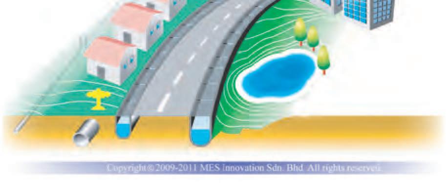
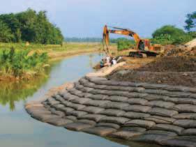
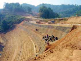
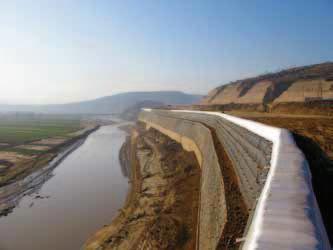
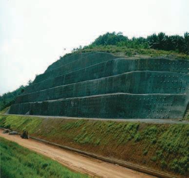
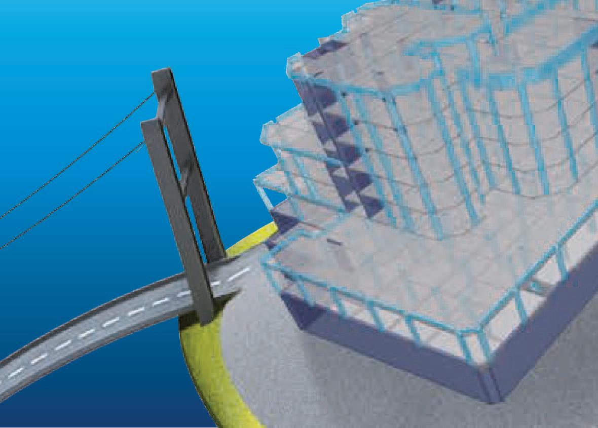
Geosynthetics for Embankment & Basal Reinforcements


Electrical grounding is necessary to limit danger to the user from by equipment failure or conductor insulation failure. Proper electrical grounding assures safety by providing a low impedance path for “tripping” protective devices such as circuit breakers and fuses when a ground fault (short circuit to ground) occurs. This saves lives. Defeating a safety ground to reduce noise is illegal, dangerous and should never be done! There are several meanings for the word “ground” which contribute to confusion and misunderstandings. Most commonly, ground refers to a return path for fault current. In electrical utility power, a ground is an actual connection to soil for the purpose of lightning diversion and dissipation, and for the purpose of keeping the exposed surfaces at the same potential as the soil.Building safety grounds provide a return path electronic systems must work in conjunction with the building (facility) safety ground. Safety ground connections that are loose or corroded
For the optimal performance of A/V systems using a technical (isolated) ground scheme, all safety grounds must terminate at only one point.
(Continued on page 19)

The elements to be considered in EMC design for an A/V infrastructure
installation are as follows:
Grounding of equipment racks
Segregation of classes of cables
Cable layout topology
Bonding Cable shielding.
GROUNDING OF EQUIPMENT RACKS
Isolate the entire equipment rack by connecting the power and signal conductor must be installed and bonded to the rack ground stud.
When the rack is sitting on or bolted to a semi-conductive surface, bolts should be considered. A few miliamps of current will produce a noise bolts should be used.
SEGREGATION OF CLASSES OF CABLES
It is important that different categories or classes of cables be adequately segregated such that they do not affect each other.
For example, low level I/O signal cables should never be mixed together with power cables.Another example is in the case of very noisy cables, such as those feeding the power of variable frequency motor hoist drive, which should be kept away from signal cables to avoid distortion.
Signal integrity is a critical factor in any A/V system design. Signals that when the signal is eventually reproduced. Every electrical signal emits its
interference, or EMI. EMI in the cabling sense is characterised by the induction of noise into a signal. This noise can stay with a signal throughout
This interference can cause a variety of signal issues depending on the type of signal, type cable and level of interference. Certain signals can potentially emit different levels of EMI. Microphone audio, for example, has highly susceptible to interference. In contrast, 240v AC power carries a and is overall less susceptible to other EMI.
installations: (Continued on page 21)
Geosynthetics for Marine & Hydraulics Engineering

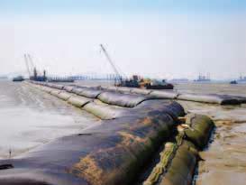
www.tencategeosynthetics.com
One way or another, audio visual signals carry information from their A/V signals are the control signals which allow the system to function either automatically or as desired by the user. These signals are transmitted over a variety of mediums including copper, glass and airwaves. The signals themselves can take the form of electrical pulses (digital); electrical waves (analogue), light beams and even radio waves. The following is a brief description of the most common types of A/V signals.
Critical to the success of A/V signals are the mediums through which they travel. A/V cables come in a variety of types, each having their own unique characteristics.Thesecharacteristicsareimportantwhendesigningasuccessful A/V system, ultimately determining which cable is appropriate for what signal. Below is a brief description of commonly referenced cable characteristics. Shielding

EARTH BONDING OF EQUIPMENT RACK
Bonds between painted or epoxy surfaces should not be accepted. It is essential that all bonds and joints provide electrically conductive low impedance paths across the bond. Theepoxybasedracksdonotprovideproperleakagepaths for the leakage currents of equipment mounted on the racks.A rack with metallic conductive surfaces, such as galvanised or chromed surfaces, is more suitable and practical.
The bonding of an equipment within a rack by looping is a very poor approach to ground and should be avoided. Ideally, an equipment rack should be bonded to the rack by direct mating of the metallic conductive surfaces of the rack. This constitutes a low impedance bond.
The bonding of one rack to another (i.e. looping) before returningtothemaingroundingpointwithintheroomisanother poor approach which should never be used. This causes potential differences within the interconnected equipment on different racks of the same row or on different rows.
ENHANCED EMC RACK BONDING
Routing signal conductors adjacent or close to ground is a very effective and proven method of reducing the undesirable effects of EMC in signal conductors (since between the signal conductor and the grounding network).
The greater the surface area of the ground, the lower the impedance and the more effective the protection, especially at higher frequencies.
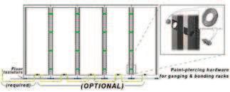
The metal chassis of racks are required by code to be bonded to ground for safety. One of the most effective ways to create a large surface area ground is to bond these grounded equipment racks together in a network. For a multiple rack installation, all racks are bonded together in an isolated rack grounding system, with a single grounding point,toavoidgroundloopandpowerinterferenceproblems.
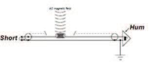
AC MAGNETIC FIELDS AND THEIR EFFECT ON SIGNAL WIRING
When diagnosing signal problems caused by
the signal path. If a signal cable with a shorted source end hums and the hum goes away when the short is lifted, the
There are two effective ways to reduce the effect of AC power conductors inside a rack.
2. Using tightly-twisted signal wire and AC power cables.
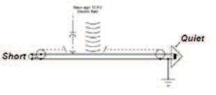
ELECTRIC FIELDS AND THEIR EFFECT ON SIGNAL WIRING
itishelpfultoopenthesourceendofthecable.Cableshields as follows.
There are many effective ways to reduce the effect of
2. Followgoodsignalpathdesignandinstallationpractices.
POWER INTERFERENCE IN PRO-AV DESIGN
Large transformers, stage rigging hoist motors and lighting
No large power transformers or motors should be located within 50 feet of a recording studio console, stages, worship platforms or control rooms.
CONCLUSION
Quite often, the electrical engineer, when designing the electrical systems for this kind of special facilities, does not implementtheprescribedEMCpracticesatall.Unfortunately, mitigation measures are only put into place after the facility is built and problems are encountered. The practices of EMC design requirements should be incorporated in the visual, studio and broadcasting facilities design.


1. INTRODUCTION
Copper is known to possess certain unique qualities that make it the best engineering material for various industrial applications. These qualities include high thermal conductivity, excellent ductility, excellent corrosion resistance in different environments, and toughness over a wide range of temperatures. In this paper, various aspects and engineering applications of different copper alloys are discussed individually. In addition, the possibility of new copper alloys is also highlighted in this paper.
Copper is an important engineering metal that has been in use for over 6000 years. It is the backbone of the electrical industry [1]. It is also the major metal in a number of highly important engineering alloys, namely, the brasses and bronzes. Pure copper in its annealed state has a tensile strength of about 200MPa, with an elongation of nearly 60% [2]. The copper alloys also lend themselves nicely to the whole spectrum of fabrication processes, including casting, machining and welding. Unfortunately, copper is heavier than iron. Although the strengths can be quite high, the strength/weight ratio for copper alloys is usually less than that for the weaker aluminium and magnesium alloys.
Copper and its alloys have been commercially important from ancient times to the present [3, 4]. The properties of these alloys continue to make them useful for the manufacture of coinage, utensils, crucial components of weaponry and jewellery. However, it is the high capability of conducting electrical current and heat that has enabled this family of metals to grow and, indeed, partly enable the accelerated growth of modern high technology products. Therefore, copper is the third most important commercial alloy system following iron and aluminum. The engineering properties of copper are dependent on the type and amount of alloying elements present and the processed condition. Furthermore, while some or many property improvements can be effected through alloying, other properties can be impaired or reduced [4]
2. UNALLOYED COPPER
Unalloyed copper is a metal with high electrical conductivity, hence it is largely used in the electrical industry. Electrolytic tough pitch (ETP) copper is the least expensive of the industrial coppers and is used for the production of wire, rod, plate and strip. ETP copper has a nominal oxygen content of 0.04%. Oxygen-free high conductivity (OFHC) copper is produced by casting ETP copper under a controlled reducing atmosphere, thereby eliminating oxygen and hydrogen embrittlement.

Copper Development Association System (CDAS) has cast alloys. Copper base alloys have a low enough freezing range so that they may be cast in permanent moulds or dies under pressure. These alloys have been found favourable in view of the requirement of resistance to tearing, pressure tightness and good mechanical properties. The rapid cooling of copper alloys in metal moulds favours better properties than slow cooling in sand moulds [4].
3. SALIENT FEATURES OF ALLOYED COPPER
Copper is widely used in its unalloyed condition as well as in alloys with other metals. In the unalloyed form, it has an extraordinary combination of properties, which makes it the basic material in the electrical industry, some of those properties being its high electrical conductivity and corrosion resistance, ease of fabrication, reasonable tensile strength, controllable annealing properties, and general soldering and joining characteristics [2, 3].
4. PHYSICAL CHARACTERISTICS OF COPPER AND COPPER ALLOYS
Copper easily bends, and is usually alloyed with other metals to toughen it. Normally, it is alloyed with tin and zinc, but it may also be mixed with silver and nickel. When mixed with considerable amounts of tin, the alloy is known as bronze, and when mixed with considerable amounts of zinc, the alloy is known as brass. However, no demarcation is drawn between brass and bronze.
silver. Halfbreed usually refers to a natural mixture of copper and silver. Copper is ductile and malleable, and is a very good conductor of electricity, second after silver. It is also used in pigments, insecticides and fungicides, although it has of late been largely replaced by synthetic chemicals [3].
5. CLASSIFICATION OF COPPER AND COPPER ALLOYS
to a designation system administered by the Copper Development Association (CDA). In this system, numbers from C100 through C799 designate wrought alloys while numbers from C800 to C999 designate cast alloys. The common wrought copper alloys are listed in Table 1. Coppers have a minimum copper content of 99.3% or higher. High copper alloys have less than 99.3% copper,
Table 1: Wrought copper alloys
Serial Number Wrought Copper Alloy Type Commercial Name
1Copper-ZincBrasses
2Copper-Zinc-LeadLeadedBrasses
3Copper-Zinc-TinTinBrasses
4Copper-TinPhosphorBronzes
5Copper-AluminiumAluminiumBronzes
6Copper-SiliconSiliconBronzes
7Copper-NickelNickelBrasses
8Copper-Nickel-ZincNickelSilver
their oxygen and impurity contents. They are electrolytic tough-pitch, oxygen-free and phosphorus deoxidised wrought coppers [2].
6. WROUGHT COPPER ALLOYS[3]
Wrought copper alloys are used to produce bus conductors, waveguides, vacuum seals, transistor components, coaxial radioparts,printingrolls,rivets,autoparts,busbars,radiator well as ammunition components. In addition, they are also used to produce pins, brazing rod, condenser plates, heat exchanger tubing, hot forgings, bellows, diaphragms, fuse clips, springs, welding equipment, nuts, bolts, stringers and threaded members, machine parts, marine protective sheathing and fastening, communication relays, ferrules and resistors.
7. CAST COPPER ALLOYS[3]
Cast copper alloys are processed to manufacture electrical and thermal conductors, safety tools, moulds for plastic
and guides, pickling hooks, and elbows used for sea water corrosion resistance. Commonly cast copper alloys are listed in Table 2.
8. ENGINEERING APPLICATIONS[8]
Electrolytic Tough-Pitch Copper
Electrolytic Tough-Pitch Copper Type ETP, CDA 110, has a minimum of 99.9% copper and nominal 0.04% oxygen content. The normal limits of oxygen in ETP copper are between 0.02% and 0.05%. It is the least expensive of the industrial coppers and is used extensively for the production of wire, rod, plate and strip. The oxygen converts some impurity elements into their oxides; on casting, the oxygen forms an even dispersion of blowholes that prevents
Table 2: Cast copper alloys
Serial Number Cast Copper Alloy Type
1CastCoppers
2CastHigh-CopperAlloys
3CastBrasses
4Cast-Manganese-BronzeAlloys
5CastCopper-Zinc-SiliconAlloys
6CastCopper-TinAlloys
7CastCopper-Tin-LeadAlloys
8CastCopper-Tin-NickelAlloys
9CastCopper-Aluminium-IronAlloys
10CastCopper-Nickel-IronAlloys
11CastCopper-Nickel-ZincAlloys
pipe cavities from forming. Upon hot working, these small blowholes are welded together [4].
Oxygen-Free Copper
cathode copper by melting and casting under a reducing atmosphere of carbon monoxide and nitrogen so that oxygen is prevented from entering the copper.The electrical conductivity of oxygen-free 99.95% copper is about the same as ETP copper. If selected cathodes of high purity copper are remelted, 99.99% oxygen-free copper can be produced and is preferred for many electronics applications. Due to the special processing of oxygen-free coppers, they are more expensive than ETP coppers [4].
Deoxidised Copper
oxygen in the copper will be converted into phosphorus pentoxide. Since phosphorised high conductivity coppers contain very little retained phosphorus, normally less than 0.009%, the high conductivity of copper is maintained. Higher levels of phosphorus are used in deoxidised high phosphorus copper CDA 122, so that these alloys may contain as high as 0.04% residual phosphorus, resulting in a lower electrical conductivity of about 85% IACS. The excess phosphorus in the copper prevents the adsorption of oxygen during hot working and annealing and allows this material to be welded [4].
Copper-Zinc Alloys
Copper-zinc alloys are categorised as brasses. Copperzinc brasses consist of a series of copper alloys with up to about 40% zinc. It has additional elements such as tin, aluminium, silicon; manganese, nickel and lead are referred to as alloy brasses. Brasses are also able to be nickel and be used for heat transfer media. The best combination of ductility and strength occurs at 70% copper and 30% zinc, hence this alloy can be used for its excellent deep drawing ability.
(Continued on page 29)
July 2012 JURUTERA | 27


The 70% copper and 30% zinc alloy is descriptively called cartridge brass and is used for other applications
Copper-60% and zinc-40% is otherwise called Muntz metal.
Small amounts of lead from 0.5% to 3% are added to many types of brasses to improve their machinability and are called leaded brasses. The addition of 1% tin to cartridge resistance in seawater. Since the British Admiralty adopted this alloy in the 1920s, it became known as admiralty brass. It was later found that small additions of arsenic, around 0.04%, could almost eliminate a common corrosion
brass was used for a long time for marine condensers.
Still later, it was discovered that replacing the tin with aluminium gave the brass a self-healing protective oxide on alloy more resistant than admiralty brass to the impingement of high velocity water. Today, a 77.5% copper-20.5% zinc-
brass for marine condensers. The addition of 1% tin to Muntz metal improves its corrosion resistance and forms an alloy called naval brass [5].
Brasses
High brasses contain 60% to 80% copper, and 40% to 60% zinc. These brasses, because of their high zinc content, have increased strength. Small additions of alloying elements, such as 1% tin to the brasses, do not greatly affect their mechanical properties. However, multiple additions of manganese, iron and tin, for example, to increase the strength of the Muntz metal. Because of its increased strength, manganese bronze is best worked in a hot condition.The addition of up to about 3% lead to improve the machinability of brasses has practically no effect on the tensile strength and hardness of the leaded brasses [6].
Unalloyed brasses are used to make coins, medals, bullet jackets, primers, plaques, jewellery base for gold plate, screen cloth, weather stripping, lipstick cases, marine hardware, angles, chains, fasteners, heat exchanger tubing and radiator cores. In addition, such brasses are processed to manufacture battery caps, musical instruments, clock brasses are processed to produce distilling tubes, aircraft turnbuckle barrels, propeller shafts, connecting rods, shafts, wear plates, clutch disks and ferrules.
Copper-Tin Alloys and tin are properly called tin bronzes. Since phosphorus is usually added to these alloys as a deoxidising agent during casting, tin bronzes are commercially known as phosphor bronzes. These alloys possess desirable properties such as high strength, wear resistance and good seawater corrosion resistance. Wrought copper tin bronzes containing from 1.25% to 10% tin are termed as phosphor bronzes since they usually contain up to about 0.1% phosphorus, which is added
Copper-Beryllium Alloys
Copper-beryllium alloys contain between 0.6% and 2%
beryllium with additions of cobalt from 0.2% to 2.5%. These alloys are precipitation-hardenable and can be heat-treated to produce tensile strengths as high as 212ksi, which is the highest strength developed in commercial copper alloys.
Copper beryllium alloys are used for tools, which require high hardness and non-sparking characteristics such as may be needed in the chemical industry. The corrosion and fatigue resistance, and strength of these alloys have made them useful for springs, gears, diaphragms and valves [9]. They are also used for electrical contacts and moulds for forming plastics.
Even though these alloys contain only a small amount of beryllium, their cost is relatively high, thus their use is the engineering requirement of an application. Copperberyllium alloys are used to make bellows, diaphragms, fasteners, lock washers, springs, switch parts, roll pins, valves, welding equipment, fuse clips, relay parts, electrical conductors, resistance welding electrodes, seam welding steels, electrode holder jaws, cable connectors, currentcarrying arms and shafts, circuit breaker parts, moulds, thermal conductors requiring strength and switch contacts. Copper-Nickel Alloys
series of solid-solution alloys of approximately 10%, 20% and 30% nickel called cupronickels. The nickel additions increase the strength, oxidation and corrosion resistance of copper. The cupronickels are used for marine condensers and tubing for conducting seawater because of their moderately high to high strength and resistance to the corrosive and erosive effects of high-velocity seawater. Since cupronickels do not work-harden rapidly, they are used for condenser tubes and plates, heat exchangers and a wide variety of chemical process equipment [10].
Copper-nickel alloys are processed to manufacture condensers, condenser plates, evaporator and heat exchanger tubing, ferrules, saltwater piping systems, communication relays, electrical springs, resistors, high strength constructional parts for sea water corrosion resistance, hydrophone cases, mooring cable wire, retainer rings, screws, pins for ocean telephone cable applications, brazing alloy, lead frames, control and sensing bellows.
9. RESEARCH ON NEW COPPER ALLOYS
The number of possible new copper alloys is endless, and superior properties. Some alloying combinations have proven to be impossible to make because of Earth’s gravity. For this reason, experimental work on new alloys has been undertaken during Skylab missions to take advantage of the weightless condition in space. Copper or copper oxide, reduces the evolution of deadly hydrogen cyanide gas when such plastics are burnt.
to improve castability and to act as a deoxidiser. Cast copper-tin bronzes have higher tin contents, about 10%, hence making copper-tin alloys unworkable, but castings containing up to 16% tin are used for high strength bearings and gear blanks. Gear-blank castings are often made by the centrifugal casting process to ensure soundness. Tin levels of about 10% are common for bearings, with variable quantities of lead being added to improve the plasticity and adaptability for bearing surfaces [7].
Bronzes
Aluminium bronzes are processed to make condenser, evaporator and heat exchanger tubes, distiller tubes, ferrules, bolts, pump parts, shafts, tie rods, overlay on steel forwearingsurface,nuts,structuralcomponents,condenser tube and piping systems, mixing troughs and blending chambers, bushings and bearings, worm gears, cams, forming rolls, dies, plunger tips, glass sealing and porcelain enamelling [8]. Silicon bronzes are used to fabricate hydraulic pressure lines, anchor screws, bolts, cable clamps, cap screws, machine screws, marine hardware, nuts, pole-line hardware, rivets, U-bolts, electrical conduits, heat exchanger tubing, welding rod and propeller shafts. Phosphor bronzes are used to manufacture electrical bourdon tubing, cotter pins, lock washers, wire brushes, chemical hardware, textile machinery, bridge bearing plates, locator bars, sleeve bushings, truss wire, perforated sheets, welding rod, heavy bars and plates for severe articles requiring good spring qualities, resiliency, fatigue resistance, good wear and corrosion resistance.
Copper-Aluminium Alloys
Copper-aluminium alloys are called aluminium bronzes, although a better name would be aluminium brasses. These alloys are quite hard, have high tensile strengths and are tough. They resist wear, fatigue and have excellent aluminium oxide.Aluminium bronzes containing up to about 10% aluminium and, with additions of about 5% iron and 5% nickel, are exceptionally strong and tough, and have excellent corrosion and oxidation resistance at elevated temperatures. These alloys are used for high-strength bearings and gear wheels and can be used for dies for deep drawing some types of stainless steels [8].
Copper-Silicon Alloys
Copper-silicon alloys are usually referred to as silicon bronzes or by their trade names such as Everdur or Herculoy. Most silicon bronzes contain between 1% to 3% silicon. Small additions of manganese and iron are sometimes added to improve their properties. Silicon resistance to corrosion and relatively high strength and toughness compared to low carbon steels. For many uses, they are low-cost substitutes for tin bronzes since, except for impingement attack, they have good seawater corrosion resistance. These alloys can be cast or hot- or cold-worked.
Some copper alloys have been developed which display aphenomenonknownasshapememoryeffect.Thesealloys their capacity to change from one shape to another upon an alteration of temperature [11]. New production methods have enabled the development by the International Copper
to a much thinner gauge in modern mills, tubing made from precision strip by either high-frequency or laser welding and the use of new soldering/brazing techniques.
10. CONCLUSION
It is concluded that copper is widely used in its unalloyed condition as well as in alloys with other metals. In the unalloyed form, it has an extraordinary combination of properties, which makes it the basic material in the electrical industry, some of those properties being its high electrical conductivity and corrosion resistance, ease of fabrication, reasonable tensile strength, controllable annealing properties, and general soldering and joining characteristics. The uses of copper and its alloys and compounds will continue to change, as they have over thousands of years, to meet modern challenges. As an essential service material that is environmentally friendly, fully recyclable and fully sustainable, there is no viable alternative to copper, the 21st Century metal.
ACKNOWLEDGEMENT
The author expresses his thanks and gratitude to the Faculty of Engineering and Technology (FET), Multimedia University (MelakaCampus),BukitBeruang,75450Melaka,Malaysia,for allowing him to write and publish this article.
Note: The author is a Principal Lecturer in Mechanical Engineering, Faculty of Engineering and Technology, Multimedia University (Melaka Campus), and may be contacted at thoguluva@mmu.edu.my
REFERENCES
[1] CopperandCopperAlloyCastingsPropertiesandApplicationsPublication TN42, CDA, Copper Development Association, UK, December 1991.
[2] Application Data Sheet, Standard Designations for Wrought and Cast Copper and Copper Alloys. Copper Development Association, New York, USA, 1998.
[3] Brandes E and Brook G (eds.) Smithells Metals Reference Book, 7th Edition dn. Butterworth-Heinemann, Oxford, UK, 1992.
[4] Hutchinson B, Sundberg R and Sundberg M, High Strength and High Conductivity Copper Alloy: A Review of Current Status and Future Potential In: (eds.) Copper ‘90 Re®ning, Fabrication, Markets. Institute of Metals, Vasteras, Sweden, pp. 245-258, 1990.
[5] Mendenhall J, Understanding Copper Alloys. Krieger, Malabar, FL, 1986.
[6] Metals Handbook, Properties and Selection: Nonferrous Alloys and Special-Purpose Materials. ASM International, Materials Park, OH, 10th Edition, Vol. 2, pp. 216-427, 1990.
[7] Pawlek F and Reichel K, The Effect of Impurities on the Electrical Conductivity of Copper. Z. Metallk. 47, 347-356, 1956.
[8] R.A. Flinn, Copper, Brass and Bronze Castings, Non-Ferrous Founders’ Society, Inc., Cleveland, 1961.
[9] R. Hultgren and P.D. Desai, Selected Thermodynamic Values and Phase Diagrams for Copper and Some of Its Binary Alloys, Incra Monograph I, International Copper Research Association, Inc., New York, 1971.
[10] W.A. Glaeser and K.F. Dufrane, The Design of Boundary Lubricated Cast Bronze Bearings, Cast Bronze Bearing Institute, Inc., 1978.

PROFESSIONAL INTERVIEW ESSAY
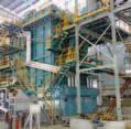
INTEGRATED Operations, commonly known by its acronym IO, is an initiative being pursued by many oil and gas companies globally. IO is also known by its various branding names in various companies such as Smart Field, Intelligent Field, Digital Oil Field, Field of the Future, etc. At PETRONASCarigaliSdnBhd(PCSB),whichistheoperating subsidiary of PETRONAS, its integrated operations initiative is known as PINTAR, which is an acronym for “PETRONAS Integrated and Real-time” Operations.
The objective of this initiative is to capitalise on the advancement of digital Information and Communication Technology (ICT) towards improving the plant or offshore platform operations, i.e. by collecting information pertaining to process and utility systems in real-time and using that information to monitor and control the performance of the plant, and facilitate proactive intervention so as to minimise downtime. This improves cumulative production or productivity which in turn enhances the company’s overall business performance.
The technology itself has been utilised for quite some time,forexample,inthespaceprogrammeofNASA,military operations by NATO and in Formula One racing. With the rapid advancement in telecommunications and computing technology, interest in their applications has expanded to the global oil and gas industry.
IO CONCEPT
There are three equally important main components which make up and support the entire IO environment, namely:
1. Business Process
end to the other, and which has to pass through various parties or individuals for them to review, approve or analyse the situations related to plant operations and performance.
2. People These are subject matter experts and/or various parties who will make the technical and business decisions in accordance with the level of authority assigned to them,
3. Technology
This represents the ICT tools used to facilitate and
data in real-time in the past due to the limitations of

bandwidth and the speed of data transfer available from telecommunication and control systems. Now, with the advancement of ICT systems, faster data transfer rates for real-time information management purposes are now possible, especially with high speed telecommunication
All three components described are inter-related and interdependent, especially when teleconferencing facilities are integrated into the entire IO environment. Again, the availability of a high-speed telecommunication link is vital.
In the Norwegian sector of the North Sea and in the Gulf of Mexico, where IO has successfully been implemented in offshore platforms, the telecommunication network
providing a reliable communication channel linking the
IO is made up of various functionality layers from the point of data collection by means of various sensing devices linked to their respective monitoring and control systems until the point of displaying the results of the analysis and/or plant status to enable the operator or higher management to make operational or business decisions respectively.
of data or information, can be summarised as follows:
1. Data Gathering
data depicting conditions or status of the processes and utilities,normallyprovidedbyDistributedControlSystem (DCS) or Supervisory Control And Data Acquisition (SCADA) system and various utility control panels, with process parameters, status and conditions of the utilities to the control and monitoring system in real-time. The electronic sensor itself has now evolved into a “Smart” sensor with diagnostic capability that helps the operator to monitor its health status. After that, all these data are normally sent and stored in a “Data Historian” server, such as the ‘PI Server’, on the platform or in the plant, This is where the telecommunication link is vital to ensure real-time data transfer at high speeds is possible especially for offshore platforms. In Malaysia, offshore platforms are located within a distance of 80km to 160km from shore.
2. Modelling, Analysis and Optimisation
These activities require special software to undertake checks, so that comparisons can be made between “what is happening now” and “what it should be”. the process or utility systems. Therefore, the affected system can be automatically controlled or manually intervened in order to bring it back to normal operating conditions with the help of experts who, at the same time, are able to access and view the information from anywhere via remote access facilities. Models are developed based on the available historical data and trends, and will help the operator or expert in identifying the symptoms of potential problems. This triggers the effort to mitigate the problem before it occurs. Similarly, the health check or rotating machinery (e.g. generators or pumps).
The maintenance philosophy utilising the concept of monitoring their operating performance and health is known as “predictive maintenance” or is generally also referred to as Condition-based Maintenance (CBM). CBM can minimise or replace the normal “planned preventive maintenance”. In principle, the maintenance is performed on a need basis rather than by routine. For the oil and gas industry, the optimisation capability is very much needed in order to optimise the or for the purpose of reservoir pressure maintenance From the above, the utilisation of resources either in the form of material use or manpower can be optimised (OPEX).
3. Collaborative Work Environment (CWE) for Improved Decision-Making
Having real-time data or information on a 24-hour basis, and the capability for it to be accessed from anywhere in decision-making pertaining to technical or business aspects of the operations. Immediate decisions can be made upon consultation with the relevant experts, who will be able to access and view the same database at the same time as the decision-maker. This mode of working is known as the Collaborative Work Environment (CWE). A collaboration centre which is normally equipped with audio-visual facilities will usually also be provided. This is the place where a group of front of the big screens displaying real-time information on any particular operational or business issue.Again, a computer-based system and telecommunication link is critical in providing this kind of work environment.
IO is very much dependent on the integration capability of the various monitoring and control systems and software usedfordatahandlingordatamanagement.Thisintegration
capability is termed as “interoperability” which overcomes the limitations of traditional proprietary systems. Various international standards to address this interoperability requirement have been developed and published such as ISO-15926 by POSC-Caesar Association (PCA)/ISO, WITSML and ProdML by Energistics, and those of a few other organisations.
IO has changed the way we use to operate and maintain the production facilities and has today created a totally different work environment enabling faster and more informed decision-making. Thus, improved performance of the industry by minimising downtime and increasing the level of safety can be expected.
If the telecommunication infrastructure is reliable and is able to guarantee the continuous availability of real-time data and video surveillance, it will be possible for production facilities to be totally unmanned and operated remotely. This would be quite similar to the concept applied by NASA in their space programme, or in a Formula One race where a collaborative environment enables a pit crew to monitor car performance in real-time and communicate important information to the driver to assist him in making decisions that could improve his chances of winning the race.
In conclusion, IO has brought a new dimension in operating a plant or production facility, by greatly improving its business value. The IO concept can also be applied to various other industries.
MGBC BOARD MEMBERS 2012-2013
We are pleased to announce that the following have been elected into the MGBC Board for 2012-2013 at the 3rd Annual General Meeting of the Malaysia Green Building Confederation held on 26 May 2012.
President Ir. Looi Hip Peu Mektricon Sdn Bhd
Vice President Ar. SarlyAdre Sarkum BDA Architects Sdn
Honorary
Board
(Sourced from BERNAMA)
(Sourced


Objective: To move REDs to GREENs What are the strategies for each group?

pub@iem.org.my


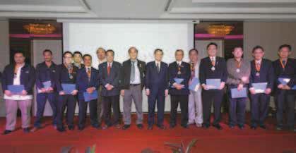
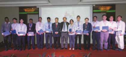
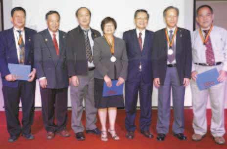
ON 19 March 2012, the ASEAN Engineering Register National Monitoring Committee (AER NMC) and the APEC/EMF International Professional presentation ceremony and networking dinner for the newly-approved entrants to AER and APEC/EMF. The ceremony, held at Armada Hotel, Petaling Jaya, was attended by Ir. Vincent Chen Kim Kieong, President of the Institution of Engineers, Malaysia, Ir. Fong Tian Yong, President of the Technological Association Malaysia (TAM), Ir. Choo Kok Beng, AER Head Commissioner, Ir. Yim Hon Wa, Chairman of AER NMC, Ir. Dr Gue See Sew, Chairman of the APEC/EMF Registration Committee, and fellow IEM Council members. The number of recipients, in accordance to their registration status are as follows:
ASEAN Engineers – 12
ASEAN Engineering Technologists – 3
ASEAN Technician – 1
Associate ASEAN Engineers – 15
APEC/EMF Registrant – 1
During CAFEO 28 held in Hanoi, Vietnam, the AFEO
Engineers to be accorded with the title Associate ASEAN Engineers (AAE). History was once again made in June 2011 when the AER Executive Committee, based at the IEM, and the AFEO Governing Board agreed to expand the ASEANEngineersRegisterintothe ASEAN ENGINEERING REGISTER (AER) to include the registration of the entire engineering fraternity comprising engineers, engineering technologists, technicians and its associates. This new initiative will indeed enhance the objective of promoting engineering mobility within the ASEAN region. The grades of the AER which were approved are as follows:
1. ASEAN Engineer
2. ASEAN Engineering Technologist
3. ASEAN Technician
Associate ASEAN Engineer
5. Associate ASEAN Engineering Technologist
6. Associate ASEAN Technician.
The ceremony also marked the second batch of Associate
Engineering Technologists and ASEAN Technicians from the Technological Association of Malaysia (TAM).
In his speech, the IEM President warmly welcomed and spoke of his appreciation of all professional engineers, engineering technologists and technicians within this region, especially from the IEM and TAM who had joined the register and took action by combining and strengthening the register. He also added that by having an integrated register, the engineering industry could help raise the status and standard of the engineering profession, improve economic growth, and increase the standard of living in the country.


THE IEM Student Section of Universiti Teknologi PETRONAS (UTP) organised a membership drive as well as an introduction to the Young Engineers Section (YES) and the Institution of Engineers, Malaysia (IEM) Student Section since its establishment in August 2011. The event was held Student Section President, Saudara Muhammad Nasrullah Annuar together with his committee members.
The main idea of the event, which started


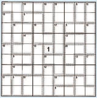
1SUDOKU Centerpiece "1"


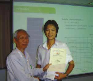
held on 12 May 2012 organised by the EETD. The speaker, Mr. Jonathan Kan, is an entrepreneur with a tertiary engineering honours degree in mechatronics from the University of New South Wales. He obtained accreditation from the ISPQ and Pusat Tenaga Malaysia for the Bosch and SMA to provide technical and warranty support for the numerous inverter installations for off-grid and hybrid solar PV solutions. ERS Energy Sdn Bhd, a company which he founded, has provided consultancy services
The talk commenced with an overview of the energy output of 49 cities worldwide and several major cities in Malaysia from solar PV resources. It continued with the typical components of the building integrated PV (BIPV) system and the difference between grid connected and off-grid connected PV systems. A brief introduction to the related standards on solar PV (e.g. MS 1837, IEC 61215 and IEC 61727) was also given.
The design and installation aspects of solar PV systems were explained through discussions on the different types and performance characteristics of solar PV modules together with some indication of their respective expected warranty periods. The typical capacities of solar PV systems for residential, commercial and solar farms with their respective voltage and other requirements were also provided.
The discussion then moved on to “off-grid” solar PV installations and, in particular, the applicable standards (such as MS IEC 62257 and MS IEC 62124) for such systems, and hybrid components including backup batteries and related charging controllers. Illustrations were provided using schematic diagrams and photographs.
TheconceptoftheFiTwasdiscussedwithsomeindicationoftheaverage cost trends of solar PV installations for economic viability considerations. The talk concluded with the speaker highlighting future technologies and trends in solar PV installations and their components, and some of the incentives offered for solar PV installations.
In the question and answer session that followed, there was active participation and interaction with the audience. The programme ended with the presentation of a token of appreciation to the speaker by the EETD Session Chairman.

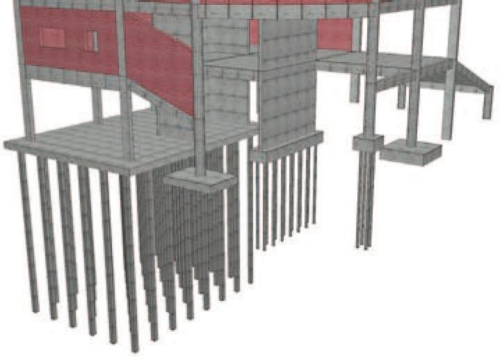
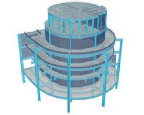
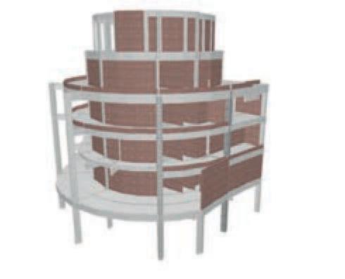
THE one-day seminar on “Underground Construction: Design, Technologies and Recent Findings” was organised by the Geotechnical Engineering Technical Division on 5 January2012attheTanSriProf.ChinFungKeeAuditorium, Wisma IEM. The seminar consisted of six lectures which were delivered by Prof. Lee Fook Hou (three lectures), Ir. Dr Toh Cheng Teik (two lectures) and Ir. Dr Leong Kam Weng (one lecture). A total of 100 participants attended the seminar.
modellingindeepexcavationsandtunnelling,Prof.Leefrom the National University of Singapore shared some insights into the Nicoll Highway collapse using a three-dimensional
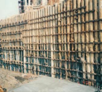
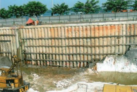
1. Maximum movement of the south diaphragm wall was larger than that of the north diaphragm wall due to the breakup of the south wall inter-panel joints under tension (no continuous walers). The breakup of the south wall inter-panel joints might have led to the twisting of the struts causing the struts to buckle and the transfer of load from the 9th level strut to the 8th level strut. A possible contributory factor to the collapse was the absence of continuous or global walers.
2. Soil arching is not an effective means of redistributing strut loads as it requires a large ground deformation to take place. In such situations, some struts would have failed before the redistribution became effective. This accentuated the likelihood of a progressive buckling of struts.
3. Location of maximum movement coincided with where the marine clay is thickest, suggesting that the 3-D location of the maximum movement.
4. even within the same strut layer, due to non-uniformity in ground conditions and preloading sequence.
5. but many of these might have been quite subtle and would not have been immediately self-evident. The curvilinear wall alignment might not have been in plane strain even for a large radius of the curvature.
In a study to examine the effect of unsupported tunnel length on ground surface settlement during the construction of the
which are conventionally not subjected to structural design, e.g. inter-panel joints in diaphragm wall and the joints between successive lining segments in a tunnel. Engineers may need to be more careful about whether one should analyse these components using an elastic model (without yield and failure) or to assume that they will undergo damage and cracking.
4. Is 3-D analysis useful for most problems? This is the wrong question to ask since all real problems are 3-D. The correct question should be whether a two-
5. 2-D analysis is not always conservative.
6. Most geotechnical analyses are still 2-D. The danger with doing exclusively 2-D analyses is that engineers get used to, not only doing, but also thinking 2-D, which in some situations can be dangerous.
7. It is true that a 3-D analysis takes a long time to perform, but hardware and software improvements have continuously reduced the required durations
In his third lecture entitled “Cement-Soil Treatment in Underground Construction: Some Issues and Recent Findings”, Prof. Lee concluded that:
1. The yield surface of cement-treated clay has a compression cap similar to that of soft clay. The main difference is that the cap is much larger, i.e. the yield stress is much higher, due to cementation.
2. At lower effective stress, cement-treated soil tends compression test.
3. At a higher pressure, undrained specimens show peak strength at yielding followed by strain softening and positive excess pore pressure. On the other hand, drained specimens show strain hardening behaviour with large volumetric compression, until a very large shear strain level, at which point shear banding occurs.
4. Microstructural examination shows progressive loss of structure as shearing continues after yielding.
5. Regardless of cement-water-soil ratio, curing pressure and time, the initial yield locus of cementtreated marine clay can be represented by the same generic curve.
6. Towards the later stages of drained shearing, the shape of the yield locus shows a progressive
7. Two main parameters affecting the uniformity of cement-soil mix are: (a) Unit weight of cement vs unit weight of soil –it should be approximately equal to minimise heterogeneity.
Fort Canning Tunnel using the NATM tunnelling method, that the maximum ground surface settlement had not been reached at the tunnel heading. Instead, it was reached at some point above the bench or towards the tail end of the bench. The reasons are:
1. Ground movement around the tunnel occured over a period of time. As pore pressure dissipated, the load from the ground was gradually transferred to the primary support system, i.e. shotcrete.
2. The shotcrete did not harden instantaneously.
3. The interaction between the steel pipe umbrella arch (also known as “All Ground Fastened” or AGF), shotcrete, partially excavated tunnel and ground was three-dimensional. The AGF behaved like a roof beam spanning between the supports located somewhere in front of the heading and behind the bench.
conclusions and recommendations were made by Prof. Lee:
1. It is important to understand real soil behaviour and which aspect of soil behaviour is critical. For instance, in the case of the Nicoll Highway collapse, strength was important, thus a simple constitutive model, e.g. Mohr-Coulomb soil model with the adoption of accurate undrained shear strengths, could be used. Using a very sophisticated soil model might be unnecessary, unfeasible and possibly risky due to the lack of knowledge of the material parameters.
what is conservative and what is not; this depends on the problem and the variables in question. One set of parameters may be conservative to some variables pile bending moments). Setting hard-and-fast rules for increased risk for errors. The recommended safeguards are to have a thorough consideration of the physics of the problem and to conduct parametric studies.
3. Most structures are designed to behave elastically under loading, and therefore, should often be analysed as such. Modelling the structure as an elastic system also often maximises the load on the structure. However, there are exceptions, for instance, when recreating a collapse or damage scenario, and for components

(b) Blade rotation number, which is a function of the number of mixing blades per meter depth, rotational speed of mixing tool and jack-in/withdrawal rate. An adequate mixing would require a blade rotation number of approximately more than 400. It was found that the unit weight effect is proportionally effect.
The second speaker, Ir. Dr Toh, presented various case “Deep Excavations with Finite Elements”. The case histories presented included circular cantilever diaphragm walls, cantilever contiguous bored pile (CBP) walls, cantilever secant pile wall, top-down construction, preloaded struts, wall with permanent soil nails, etc. Ir. Dr Toh informed
Clough and O’Rourke (1990). For walls associated with the top-down construction method (high support stiffness), the
byCloughandO’Rourke(1990).Ir.DrTohconcludedthatthe comprehension of soil behaviours, mechanics of excavation and soil structure interaction coupled with the practical knowledge of construction methods and excavation logistics would enable an economical and safe design. In his second lecture entitled “Soil Mixing and Jet Grouting as Excavation Support”, Ir. Dr Toh shared his experience in grouting using three case histories.
The case histories presented are:
1. The use of jet grout behind a strutted CBP wall to reduce ground movements (caused by excavation) to a negligible level.
2. Soil-cement mix to form an embedded wall for a relatively low height excavation in very soft marine clay.
3. Jet grout slab with diaphragm wall and top-down construction for a deep excavation in soft clay.
The last lecture entitled “Applications of Deep Soil Mixing (DSM)” was presented by Ir. Dr Leong. He concluded that to ensure reliable and successful applications of the DSM technique, the following aspects of design and operation must be properly considered:
1. Design considerations:
(a) Suitability of soil; (b) Design and analysis of DSM; (c) DSM pattern and treatment depth.
2. Operation considerations:
(a) QA/QC in mixing process; (b) Degree and uniformity of mixing; (c) Sequence of mixing; (d) Coring and testing.
At the end of each of the lectures, the relevant speaker answered questions from the audience. Lastly, a token of appreciation was presented to each of the speakers. The


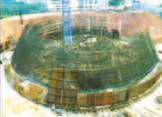
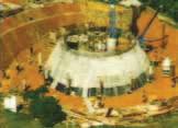
MY wife and I, together with some friends, travelled to Zhangjiajie to tour the UNESCO World Heritage Forest Park of unique towering mountain peak formations. The Zhangjiajie Mountains were also popularised by the movie “Avatar”. We then travelled seven hours eastward by road, running almost parallel to the Yangtze River to Yichang, the World Energy City.
The Three Gorges Project (TGP) was built across the Yangtze at Yichang in Hubei Province, some 1,800km upstream of Shanghai. The TGP is the world’s largest hydroelectric power plant (21,000MW capacity). The annual generated capacity in 2009 was 79.4TWh. However, the Itaipu Dam (by Brazil and Paraguay with a smaller 14,000MW capacity), which opened in 1984, has a larger annual generated capacity of 91.6TWh.
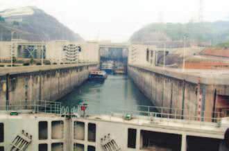
Nevertheless, with 32 turbines, the TGP production output is set to rise when the dam is fully impounded at a maximum of 175m from the current level of about 162m. The power supply coverage radius exceeds 1,000km, hence covering over 50% of the Chinese territory.
The construction of the TGP, from 1994 until the commencement of operation in 2003, culminated a long 90year period of dream, gestation, planning and much human Yat-Sen of the Kuomintang Party in 1919. The construction with full completion in 2009 was carried out during the New Communist Party era, thus transgressing the political divide.
From Yichang, we boarded the President Prime luxury cruise ship, intending to have a leisurely 4-day cruise 660km upstream to Chongqing City, including an initial 4-hour each) designed for 10,000-tonne vessels. The shiplocks would raise each transiting vessel from 62m downstream to a maximum level of 175m upstream.

Unfortunately, due to the heavy river vessel congestion, regular leisure ships were no longer allowed to transit the shiplocks at will. We, therefore, had to be contented with only viewing the dam, the shiplocks and other facilities in the accessible areas of the TGP.
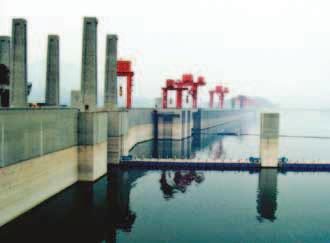
Another transit facility in the form of a 11,800 tonne capacity 113m vertical ship lift has been under construction since 2007. The lift, catering for 3,000 tonne vessels is scheduled for completion in 2014, cutting the transit time to only 45 minutes.
The TGP at 180 billion Renminbi (or about RM90 billion) is China’s pride and touted as an engineering and economic feat. Besides power generation, it also serves the functions increase in shipping operations, allowing 10,000 tonnage
However, its success came with a heavy toll from the social, cultural, environmental and human perspectives. The initial impounding of the dam from 2003 was made resettlement of some 1.3 million of the population and towns, 1,352 villages and 657 factories.
The 350 multinational passengers had a relaxing and WuGorgeandQutangGorgewithdailystopsatvariouslocal jetties. Along the way, we passed under many spectacular long span bridges built across the Yangtze River. We also passed by the entirely new booming Badong township where up to 100,000 of the resettled population now live in two- or three-storey high western style buildings with modern facilities. Surely, the TGP and the Yangtze will become increasingly popular as tourist attractions.
To All Members,
CANDIDATES APPROVED TO SIT FOR YEAR 2012 PROFESSIONAL INTERVIEW
The following candidates have been approved to sit for the Professional Interview for 2012. to passing the year 2012 Professional Interview. A MONTH from the date of
Honorary Secretary, NEW APPLICANTS
Name CHEMICAL ENGINEERING
AKMAL JUNAIDI BIN
HAMZAH BE HONS (USM) (CIVIL, 1999)
CHAU ZHENG HANGBE (NANYANG, SINGAPORE) (CIVIL, 2004) CHONG SAU HONGBSC (ULSTER POLYTECHNIC) (CIVIL, 1984)
JUHAIRI BIN HASHIM BE HONS (USM) (CIVIL, 1998)
KASUMAZAILY BIN HJ KUSSENAN BE HONS (UTM) (CIVIL, 2005
LAI CHUNG HEEBE HONS (NUS) (CIVIL, 2004) MSc(NATIONAL UNI OF SINGAPORE)(CIVIL,2007)
MUSTAFA MAAROF B. JUNID BE HONS (UTM) (CIVIL, 2001)
ROSILAWANI BINTI
SULONG BE HONS (UTM) (CIVIL, 1995)
SALWA BINTI RAMLYBE HONS (USM) (CIVIL, 1999) ME (LUNDS) (WATER RESOURCES, 2008)
ELECTRICAL ENGINEERING
MAT RAHIM BIN ABDUL GHANI BE HONS (UiTM) (ELECTRICAL, 2002) NGU KAT LUNGBE HONS (UMS) (ELECTRICAL & ELECTRONIC, 2007) ME (UM) (ELECTRICAL, 2010)
ELECTRONIC ENGINEERING TAN TIAN SWEEBE HONS (UTM) (ELECTRICALMECHATRONIC, 2001) MSc (UTM) (ELECTRICAL, 2004) PhD (UTM) (ELECTRICAL, 2009)
INSTRUMENTATION & CONTROL ENGINEERING
RIDZUAN IBNIBE HONS (UNITEN) (ELECTRICAL & ELECTRONIC, 2000) YANG SOO SIANG BE HONS (SUNDERLAND) (ELECTRICAL & ELECTRONIC, 1994) MSc (BRADFORD) (CONTROL, 1996) PhD (BRUNEL) (CONTROL & SYSTEM, 2004)
MECHANICAL ENGINEERING AHMAD KAMSAN BIN MUSABE HONS (UTHM) (MECHANICAL, 2008) CHE JEIB BIN CHE SAIDBSc (ALABAMA) (MECHANICAL, 1994) ROSMAWATI BINTI ZAHARI BE HONS (UM) (MECHANICAL, 2003) TRANSFER APPLICANTS Name CHEMICAL ENGINEERING 47607MUHD AIMAN AFIQ BIN ABU BAKAR BE HONS (UTP) (CHEMICAL, 2008)

CHEMICAL ENGINEERING 22447AHMAD KHAIRUL HAKIMIN BIN
(CATHOLIC UNI OF LEUVEN BELGIUM, 1988) 19386WONG TZE CHEONG @ THOMAS BE HONS (HERTFORDSHIRE) (CIVIL, 1998) 22946WONG WOAN JIUANBE HONS (USM) (CIVIL, 2001)
36410YAP MING TZERBE HONS (CURTIN) (CIVIL & CONSTRUCTION, 2008) ELECTRICAL ENGINEERING 24573CHEE WENG PEOWBE HONS (USM) (ELECTRICAL, 2005) MECHANICAL ENGINEERING 37071MOHD FAIZ AMIR BIN MOHD SHITH BE HONS (UTP) (MECHANICAL, 2007)
49612MOHD KHOUSHANI BIN MOHD NAIM BE HONS (MELBOURNE) (MECHANICAL, 2005 )
16587SHAHRUM BIN ABDULLAH BE HONS (UKM) (MECHANICAL, 1995) MSC (LOUGHBOROUGH, UK) (ENGINEERING DESIGN, 1997)

NAME: (please use capital letters for
IEMMEMBERSHIPNO:
P.ENGNO:
GRADE:
DATE:
NOTE: Kindly attach a photocopy of your MEMBERSHIP CARD to this Form
ECPNAME:
ADDRESS:
POSTCODE: STATE:
FIRSTDEGREE/ UNIVERSITY/ DISCIPLINE:
POSTGRADUATEDEGREE/ UNIVERSITY/ DISCIPLINE:
OTHERPROFESSIONALAFFILIATION/REGISTRATION:
TELEPHONE:
Date received:
DATEOFGRADUATION:
DATEOFGRADUATION: