THE MONTHLY BULLETIN OF THE INSTITUTION OF ENGINEERS, MALAYSIA
JANUARY 2015
KDN PP 1050/12/2012 (030192) ISSN 0126-9909
Past, Present Future Past, Present
Sustainability In Concrete Structures
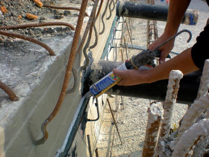
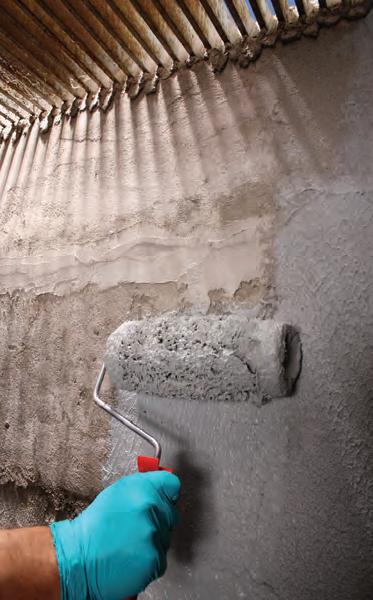
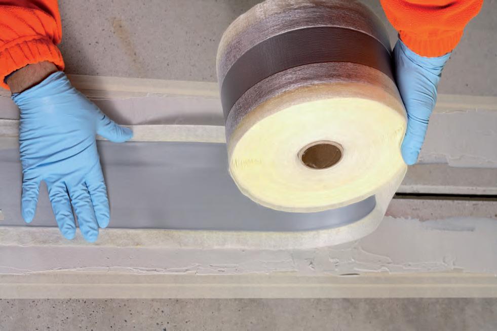
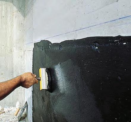
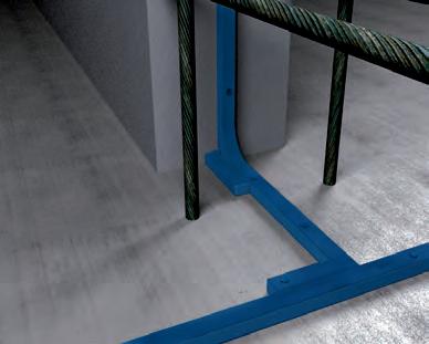
The Solution to Sustainability In Concrete Structures
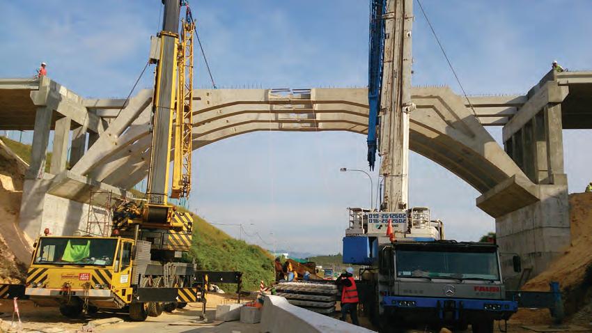
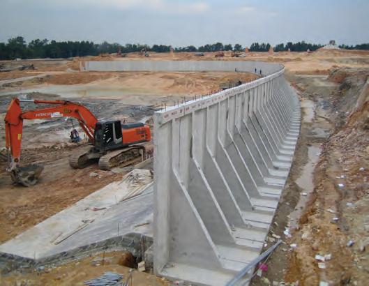
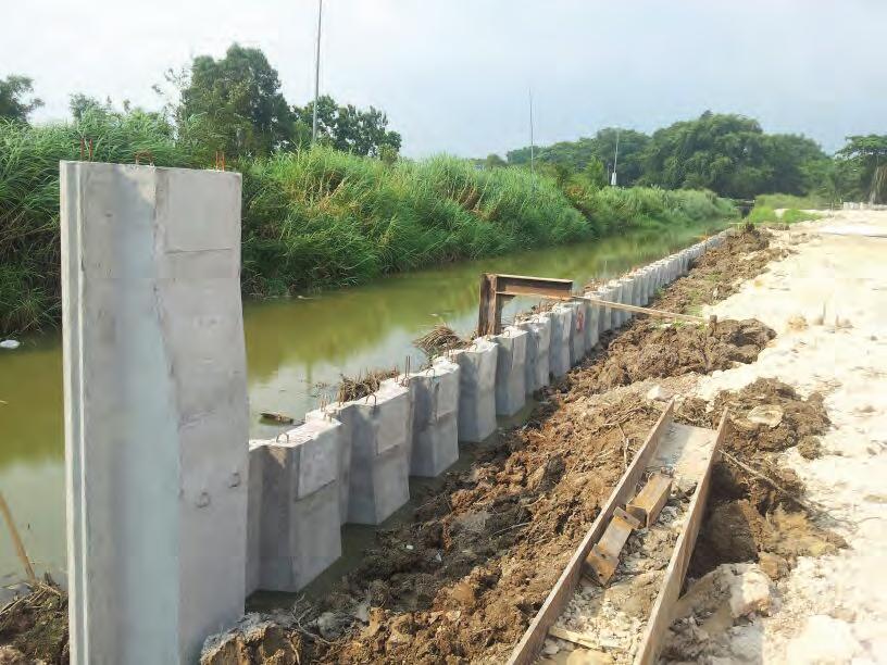
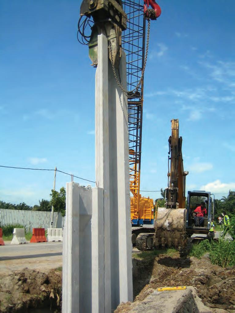
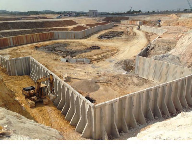
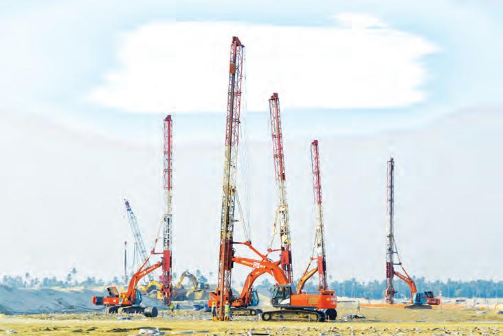
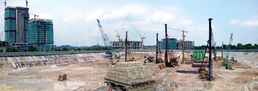
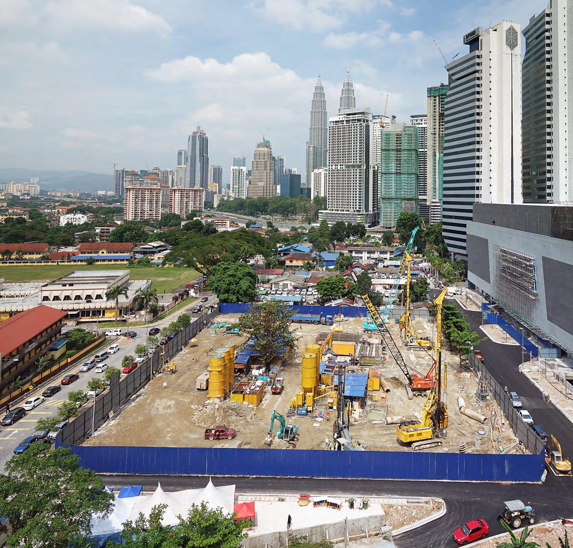
Lakefront Residence at Cyberjaya is a new residential township which personifies modern sophistication and stylish living. Developed on only 17% of 23 acres of freehold land, Lakefront Residence delivers a seamless blend of city living, green landscapes and modern facilities. This luxury condominium project is expected to be completed by year 2018.
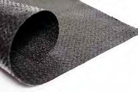
Approximately 17,000m³ of XYPEX Admix C-1000NF will be used to the R.C. Basement Slab at CP2 Raft Slab, Boundary Retaining Wall, R.C. Retaining Wall and Lift Pit. Its ability to selfheal static hairline cracks up to 0.4mm wide, resist extreme hydrostatic pressure, and chemical protection, will contribute to enhance the durability, increase service life and reduce future maintenace costs of this structure very long into the future.
For more information on how our solutions can provide sustainable benefits for your concrete assets, please visit our website at www.xypex.com.au or LinkedIn Page.
The Illustration photos courtesy of MCT Consortium Berhad
THE MONTHLY BULLETIN OF THE INSTITUTION OF ENGINEERS, MALAYSIA
Circulation and Readership Profile
Our esteemed readership consists of certified engineers, decision making corporate leaders, CEOs, government officials, project directors, entrepreneurs, project consultants, engineering consulting firms and companies involved with engineering products and services.
JURUTERA is circulated to more than 30,000 registered members of The Institution of Engineers, Malaysia (IEM), with an estimated readership of 120,000 professionals.
Advertising Benefits
Our business partners can be assured that their products and services will be given the circulation and exposure it deserves, thus maintaining a sustained advertising presence to our core readers of decision-making engineers and technical experts. Our website offers an even wider market reach, with added international presence, aided by our international affiliation with official engineering bodies all over the world. Our online and offline advertising features such as banner advertising, article sponsorship and direct e-mail announcements have proven to be successful marketing strategies that will set the businesses of our partners apart from their competition.
YANG DIPERTUA / PRESIDENT
Y.Bhg. Dato’ Ir. Lim Chow Hock
TIMBALAN YANG DIPERTUA / DEPUTY PRESIDENT
Ir. Tan Yean Chin
NAIB YANG DIPERTUA / VICE PRESIDENTS
IEM Registered on 1 May 1959
Ir. P.E. Chong, Ir. Prof. Dr Wan Mahmood bin Wan Ab. Majid, Ir. Prof. Dr Lee Teang Shui, Ir. David Lai Kong Phooi, Y.Bhg. Dato Ir. Dr Andy Seo Kian Haw, Ir. Lee Weng Onn, Ir. Gopal Narian Kutty
SETIAUSAHA KEHORMAT / HONORARY SECRETARY
Ir. Gunasagaran a/l Kristnan
BENDAHARI KEHORMAT / HONORARY TREASURER
Ir. Prof. Dr Jeffrey Chiang Choong Luin
BEKAS YANG DIPERTUA TERAKHIR / IMMEDIATE PAST PRESIDENT
Ir. Choo Kok Beng
BEKAS YANG DIPERTUA / PAST PRESIDENTS
Y.Bhg. Dato’ Ir. Pang Leong Hoon, Y.Bhg. Academician Tan Sri Dato’ Ir. (Dr) Hj. Ahmad Zaidee bin Laidin, Y.Bhg. Dato’ Ir. Dr Gue See Sew, Y.Bhg. Datuk Ir. Prof. Dr Ow Chee Sheng, Y.Bhg. Academician Dato’ Ir. Prof. Dr Chuah Hean Teik
WAKIL AWAM / CIVIL REPRESENTATIVE
Ir. Prof. Dr Mohd. Zamin bin Jumaat
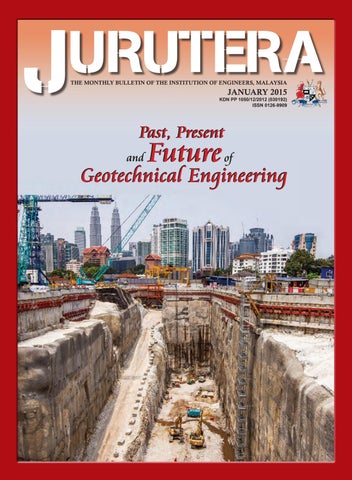
Front Cover : Photo is courtesy of MMC Gamuda KVMRT (T) Sdn. Bhd.
MAJLIS BAGI SESI 2014/2015 (IEM COUNCIL SESSION 2014/2015) FEATURE ARTICLES
Engineering
WAKIL MEKANIKAL / MECHANICAL REPRESENTATIVE
Ir. Dr Kannan M. Munisamy
WAKIL ELEKTRIK / ELECTRICAL REPRESENTATIVE
Ir. Ali Askar bin Sher Mohamad
WAKIL STRUKTUR / STRUCTURAL REPRESENTATIVE
Ir. Hooi Wing Chuen
WAKIL KIMIA / CHEMICAL REPRESENTATIVE
Ir. Prof. Dr Abdul Aziz bin Abdul Raman
WAKIL LAIN-LAIN DISPLIN / REPRESENTATIVE TO OTHER DISCIPLINES
Ir. S. Kumar a/l Subramaniam
WAKIL MULTIMEDIA / MULTIMEDIA REPRESENTATIVE
Engr. Abdul Fattah bin Mohd. Yatim, M.I.E.M.
AHLI MAJLIS / COUNCIL MEMBERS
Ir. Lee Boon Chong, Ir. Tu Yong Eng, Ir. Lai Sze Ching, Ir. Yap Soon Hoe, Ir. Li Thang Fai, Ir. Juares Rizal bin Abd. Hamid, Ir. Norazman bin Mohamad Nor, Ir. Ellias bin Saidin, Ir. Assoc. Prof. Dr Jimmy Mok Vee Hoong, Ir. Dr Tan Chee Fai, Ir. Kok Hee Poh, Ir. Tiong Ngo Pu, Ir. Yau Chau Fong, Ir. Teh Piaw Ngi, Ir. Assoc. Prof. Ahmad Kamil bin Arshad, Ir. Kim Kek Seong, Ir. Chong Chin Meow, Ir. Chin Kuan Hwa, Ir. Assoc. Prof. Dr Vigna Kumaran Ramachandaramurthy, Ir. Lee Cheng Pay, Ir. Ong Ching Loon, Ir. Gary Lim Eng Hwa, Y.Bhg. Dato’ Ir. Noor Azmi bin Jaafar, Ir. Aminuddin bin Mohd. Baki, Ir. Mohd. Radzi bin Salleh, Ir. Ong Sang Woh
PENGERUSI CAWANGAN / BRANCH CHAIRMAN
1. Pulau Pinang: Ir. Dr Mui Kai Yin
2. Selatan: Ir. Assoc. Prof. Hayati binti Abdullah
3. Perak: Ir. Dr Perumal Nallagownden
4. Kedah-Perlis: Ir. Chua Teik Seng
5. Negeri Sembilan: Ir. Shahrin Amri bin Jahari
6. Kelantan: Ir. Hj. Syed Abdul Rahman bin Syed Abdullah
7. Terengganu: Ir. Hj. Abdullah Zawawi bin Mohd. Nor
8. Melaka: Ir. Nur Fazil Noor Mohamed
9. Sarawak: Ir. Haidel Heli
10. Sabah: Ir. Tan Koh Yon
11. Miri: Ir. Steven Chin Hui Seng
12. Pahang: Ir. Tuan Haji Ahmad Kamal bin Kunji
AHLI JAWATANKUASA INFORMASI DAN PENERBITAN / STANDING COMMITTEE ON INFORMATION AND PUBLICATIONS 2014/2015
Pengerusi/Chairman: Ir. Prof. Dr Lee Teang Shui
Naib Pengerusi/Vice Chairman: Ir. Dr Tan Chee Fai
Setiausaha/Secretary: Ir. Lau Tai Onn
Ketua Pengarang/Chief Editor: Ir. Prof. Dr Lee Teang Shui
Pengarang Buletin/Bulletin Editor: Ir. Mohd. Khir Muhammad
Pengarang Prinsipal Jurnal/Principal Journal Editor: Ir. Prof. Dr Dominic Foo Chwan Yee
Ahli-Ahli/Committee Members: Y.Bhg. Datuk Ir. Prof. Dr Ow Chee Sheng, Engr. Abdul Fattah bin Mohamed Yatim, M.I.E.M., Ir. Dr Kannan a/l M. Munisamy, Ir. Siow Yun Tong, Ir. Chin Mee Poon, Ir. Yee Thien Seng, Ir. Tu Yong Eng, Ir. Ong Guan Hock, Engr. Aida Yazrin Mohd. Khairi, Engr. Kok Jing Shun
LEMBAGA PENGARANG/EDITORIAL BOARD 2014/2015
Ketua Pengarang/Chief Editor: Ir. Prof. Dr Lee Teang Shui
Pengarang Buletin/Bulletin Editor: Ir. Mohd. Khir Muhammad Pengarang Jurnal/Journal Editor: Ir. Prof. Dr Dominic Foo Chwan Yee
Ahli-ahli/Committee Members: Ir. Ong Guan Hock, Ir. Lau Tai Onn, Ir. Yee Thien Seng
IEM Secretariat: May Lee
Back-analyses of Slope Failures to Derive Strength Parameters in the Ground .......................................................16
Instrumented Low Embankment on Stone Columns for the Ipoh-Padang Besar Double Tracking Project.............................23
Rationalised Settlement Criteria for Pile Load Test..............................................................27
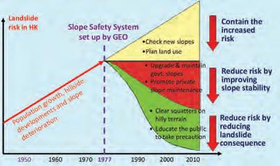
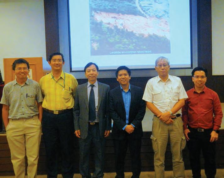
One-Day Short Course on Slope Safety System in Hong Kong..........................................36
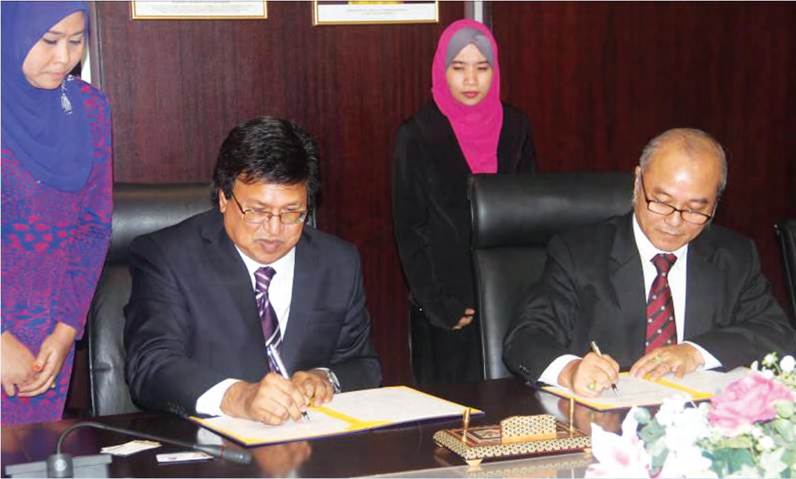
Another Milestone to “Engr” Recognition: IEM Signs MoU with Universiti Teknologi Mara (UiTM).........................................................39
by Ir. Yee Thien Seng Chairman of Geotechnical Engineering Technical Division
Ir. Yee Thien Seng is the Chairman of Geotechnical Engineering Technical Division. He is the principal of Geo.Consult, a practice offering expert and specialist consultancy to the construction industry and in particular, on geotechnical engineering aspects. He has authored and co-authored more than a dozen technical papers in local and international conferences. Ir. Yee is an expert witness and accredited checker for design of geotechnical engineering works registered with the Board of Engineer Malaysia.
State of Geotechnical Engineering
In 1989, the International Symposium on Trial Embankments on Malaysian Marine Clays was held in Kuala Lumpur, followed by the seminar on Geotechnical Aspects of the North-South Expressway the following year.
The first Malaysian Geotechnical Conference was held in 2004. These events covered practically all geotechnical engineering aspects in the country. It was expected that engineering practice would be steered in the right direction, one founded on scientific and rational tenets rather than arbitrariness.
However, the following two commonly heard statements today reflect the position of geotechnical engineering in the building industry:
1. “The soil there is very bad.”
2. “We have carried out a site investigation to confirm our design.”
The first is invariably used whenever a distressed construction or facility surfaces. It suggests that engineers lack the ability to assess ground responses before construction takes place. It runs contrary to the fact that it is a design engineer’s duties to evaluate possible issues that ground response will pose to a proposed facility, as well as to identify and detail measures to mitigate each and every one of these issues.
The second indicates a strange logic to the objectives of conducting a site investigation. It trivialises the purpose of such investigations. Taken literally, it means the design process is completed first and a site investigation is made as a cursory endeavour to confirm that the ground is suitable for the design rather than that the design is being made appropriate to the ground in addressing its potential adverse responses.
Furthermore, a plethora of less than satisfactory performing infrastructures constructed on soft ground as well as some spectacular slope failures have continued to appear. These have severely dented the image of geotechnical engineering and that of civil engineers.
In view of this state of affairs, IEM has, in the last decade, taken great effort to instill a fundamental understanding of soil mechanics through short courses on the subject, presented by academics. But progress on this front has been slow. This will continue to be the case until the senior engineers, those who lead engineering teams, are able to embrace the transformation themselves.
Thank you.
DIMENSION PUBLISHING SDN. BHD. (449732-T)
Level 18-01-03, PJX-HM Shah Tower, No. 16A, Persiaran Barat, 46050 Petaling Jaya, Selangor Darul Ehsan, Malaysia. Tel: +(603) 7493 1049 Fax: +(603) 7493 1047 E-mail: info@dimensionpublishing.com Website: www.dimensionpublishing.com
For advertisement placements and subscriptions, please contact: DIMENSION PUBLISHING SDN. BHD. (449732-T) at +(603) 7493 1049, or E-mail: info@dimensionpublishing.com
Subscription Department E-mail: subscription@dimensionpublishing.com
Printed by
HOFFSET PRINTING SDN. BHD. (667106-V) No. 1, Jalan TPK 1/6, Taman Perindustrian Kinrara, 47180 Puchong, Selangor Darul Ehsan, Malaysia. Tel: +(603) 8075 7222 Fax: +(603) 8075 7333
Mailer
PERFECT MAIL SERVICES (648839-P)
14 Jalan TSB 2, Taman Perindustrian Sungai Buloh, Sungai Buloh, Selangor Darul Ehsan, Malaysia. Tel: +(603) 6156 5288
JURUTERA MONTHLY CIRCULATION : 30,000 COPIES
Submission or placement of articles in JURUTERA could be made to the:Chief Editor
Graphic Designer NABEELA AHMAD beela@dimensionpublishing.com
Advertising Consultants ABDUL AZIM BIN SHAARI & THAM CHOON KIT azim@dimensionpublishing.com ckit@dimensionpublishing.com
Accounts cum Admin Executive YONG YEN YIN yenyin@dimensionpublishing.com
PUBLICATION DISCLAIMER
COPYRIGHT
Future of Geotechnical Engineering in Malaysia
by A. Pfordten
By Ir. Dr Ooi Teik Aun
President of the Southeast Asian Geotechnical Society for 1993-1996, 2010-2013 and 2013-2016. He is also the ICE Country Representative for Malaysia.
Dato’ Ir. Dr Gue See Sew was the President of the Institution of Engineers, Malaysia (IEM) for the 2001 to 2003 term. He also served as the International Chairman of the Coordinating Committee of APEC Engineer from 2001 to 2005 and 2007 to 2011. He was awarded The Construction Professional of the Year Award at the Malaysian Construction Industry Excellence Awards in 2006, the ASEAN outstanding Engineering Award at the Conference of ASEAN Federation of Engineering Organisations in 2007 and Federation of Engineering Institutions of Asia and the Pacific (FEIAP) Engineer of the Year 2010. He is currently the Chief Executive Officer of G&P Professionals Group.
Ir. Kenny Yee Kwong Sing is Honorary Secretary-General of the Association of Geotechnical Societies in Southeast Asia (AGSSEA). He serves as a member in TC-211 “Ground Improvement” and ATC-6 “Urban Geoengineering” of the International Society of Soil Mechanics and Geotechnical Engineering (ISSMGE).
Geotechnical engineering is a relatively new field in Malaysia. With the increase in number of infrastructure projects and mega-projects, there was a shortage of engineers earlier. Today, however, Malaysia has her fair share of experts in the field. JURUTERA speaks to several past Chairmen of IEM-GETD (Geotechnical Engineering Technical Division) Ir. Dr Ting Wen Hui, Ir. Dr Ooi Teik Aun, Dato’ Ir. Dr Gue See Sew, Ir. Kenny Yee Kwong Sing, and Ir. Yee Yew Weng to learn more about the prospects in geotechnical engineering.
QWhat are the changes you have noticed in the practice of geotechnical engineering here in the last 50 years? Are we on the right track?
Ir. Dr Ting Wen Hui: There have been advances such as:
1. The widespread availability of jacked-in piles replacing small bored piles where non-vibration piles support is required
2. Large diameter bored piles up to 3m diameter have been installed for very large superstructure loads
3. Mass ground mixing with stabilisers to improve poor ground has been introduced.
QWhat are the prospects for geotechnical specialists today? Have geotechnical specialist contractors made good progress in developing local construction technology for exporting? If not, what do you suggest the local specialist contractors do?
Ir. Kenny Yee Kwong Sing: Geotechnical engineering has definitely come of age in this country. Of the 40-plus construction companies listed in the Bursa Malaysia, 10% are involved in geotechnical works. A google search shows 9 local institutions offering postgraduate courses (MSc/PhD) in geotechnical engineering. It is clear that geotechnical engineering is firmly founded on a path of continuing development. I believe the prospect for geotechnical specialists is good in this country and the region.
On the subject of geotechnical specialist contractors, I can only draw upon my experience as a specialist contractor in the field of ground improvement. Back in the early 1980s, there were only a few contractors in ground improvement techniques. With the rapid expansion in housing and infrastructure developments, geotechnical engineers and contractors have to deal with less favourable sites such as coastal lowlands and swamps. A number of mega-size projects would be economically non-viable and/or technically non-feasible if they were constructed using conventional methods meant for good ground conditions. In this aspect, contractors have played a major role in the development of new construction methods and advanced construction plant and equipment. With the industry witnessing a strong growth during the 7th and 8th Malaysia Plan (1996 – 2005), it was necessary to adopt fast track implementation processes to meet demands. The design and build method was used. People used to say that contractors were taken out of the fryingpan into the fire for they have taken additional responsibility for design – the paradigm of design-and-built specialist contractors. Fortunately, they stood up to this baptism of fire.
With this rich experience gained, many local contractors have ventured overseas and made good progress. This success story is based on hard work and endurance.
Ir. Dr Ooi Teck Aun has been an active member of IEM since the 1970s. He is the principal interviewer for the IEM and ICE Professional Interview and also the
By Ir. Kenny Yee Kwong Sing
By Dato' Ir. Dr Gue See Sew
"As a young engineer you must start from the bottom. You must work on the ground to understand the issues. The best thing for you is to learn from a good master."
Ir. Dr Ooi Teik Aun
QThe interpretation of soil characterisation is a joint effort between geotechnical engineers and engineering geologists. How can we integrate the responsibility of each individual when it comes to geotechnical design? Should there be a separate geological report and a geotechnical report, with each being responsible for their work?
Ir. Dr Ooi Teik Aun: Geotechnical engineers are different from engineering geologists who study the formation of rock. When geologists talk about the age of soil formation, they talk in time frames of millions of years. They look at things quite differently from an engineer's perspective.
Geologists will determine whether a rock is full of faults or have crack lines. He may say it is a big fault and is active though the last movement was 100,000 years ago.
For an engineer, a structure has a lifespan of perhaps only 120 years. After that it will most likely be demolished. So he thinks: “If there is a fault I can stitch it, do rock bolting or some other thing. It's OK to build because I have already tested it and found the movement to be insignificant.”
The geologist must carefully examine everything and then present his findings to the engineer.
The engineer must take the geological report into consideration. But the geologist cannot say “you cannot build here because it's not safe”. The engineer is the one who determines whether it is safe to build.
It is two separate reports because when you do a borehole, a geologist will dig a hole in the ground to do a physical survey and then make his report. The engineer takes this report and does a geotechnical report in relation to the structure that will be built.
However, clients in private projects want to save money (this doesn't happen with government projects), so they will tell the geologist to write the report, including the so-called engineering report.
Ir. Dr Ting Wen Hui: There need not be conflict between geotechnical engineers and geologists. The former is employed to manage and consult on design and construction. In the interpretation of the mechanics of ground conditions, geological features often have a role to play and a geologist’s advice may be sought where required.
Dato’ Ir. Dr Gue See Sew: Geological input is needed by geotechnical engineers such as mapping of geological features for dams. Engineering geologists need to flag geotechnical engineers on areas that need further investigations for the properties of the sub-surface. Geological studies should be included in geotechnical reports for effective incorporation of the findings in the investigations and analyses.
Ir. Yee Yew Weng: I believe this to be more a political contention rather than a technical argument. An engineer needs to understand geology if, for instance, he is designing foundations in rock. If he is learned in geology, either from training or from experience, he can apply such knowledge to his design. If he does not have the necessary knowledge, he should consult a geologist. This is common sense, so I don’t see why we need legislation.
Ir. Dr Ting Wen Hui was a past President of IEM for the 1995 to 1997 session. He is also a past president of the Southeast Asian Geotechnical Society, serving from 1983 to 1985 and a former lecturer in University of Malaya.
By Ir. Dr Ting Wen Hui
Ir. Yee Yew Weng is the Secretary General of the Malaysian Geotechnical Society. He also serves as a Committee Member of the South East Asian Geotechnical Society and AGSSEA, and Chairman of the Organising Committee Prof Chin Fung Kee Lectures. He is currently the director of Keller ASEAN.
By Ir. Yee Yew Weng
"You must find the right place to work and look for the right mentor."
Ir.
Dr Ooi Teik Aun
QQ"The engineer cannot do what he likes without looking at the geological report."
Ir. Dr Ooi Teik Aun
What are the prospects for geotechnical specialists today? Have geotechnical specialist contractors made good progress in developing local construction technology for exporting? If not, what do you suggest the local specialist contractors do?
Ir. Dr Ooi Teik Aun: Previously, this was because we never really studied it. We thought it would be expensive. However, you must consider factors such as destruction to environment. For example, the construction of the MRT lines in Bangsar. They cut the slope and built structures close to residential houses and other structures.
There is a cost to the house owners. Property prices may drop and during construction, residents have to put up with the noise and perhaps workers who peep into their homes.
The structures could have been replaced by tunnels but of course it is more expensive. However, in the long term, it is better for the environment as everything is underground and looks neat.
We have never put emphasis on tunnelling. IEM actually formed a tunnelling division in 2000 and I was the founding Chairman of the Tunnelling and Underground Space Technical Division.
We have been trying to promote the use of underground space as a sustainable method of development as there are many advantages. Firstly, you don't need to cut down hills so there is no risk of landslides. During construction, the workers are underground, so there is little disturbance.
Elevated structures disturb lives. Even after construction is completed, the huge structures cause traffic congestion and there is always danger from the fast trains. Underground, it is safer. Even if the trains jump the track, they are confined in the tunnels. Underground rail track tunnels are uni-directional, so there will be no such thing as a collision.
R&D is important for advancing the knowledge and practice of geotechnical engineering. Currently this is carried out separately by universities, practitioners (i.e. consultancies) and government agencies. Should we encourage collaborations or should we leave it to the free-market force?
Dato’ Ir. Dr Gue See Sew: Improvements to practice require R&D culture. So practitioners need to collaborate with universities and research agencies. They should gather R&D topics and the areas of practice that need improvements, such as simplified and improved methods of testing to obtain soil properties for slope analyses.
Q
What are the foreseen improvements of roles by the consultants and contractors under the popular contractual setting presently favoured in Malaysia?
Ir. Yee Yew Weng: I have worked in consultancy for 13 years and in contracting, for 12 years. Contractual settings can be fairly diverse, depending on project and organisations. The consultant used to be responsible for all design aspects and if something goes wrong, the lawyers go after him. Nowadays, it is less clear, as the party with the deepest pocket normally cannot escape liability. Construction controls are far less stringent here than say, in Hong Kong and in Singapore. The authorities allow a lot of self-regulation among professional bodies. This should not be abused, especially when it involves public safety.
Q
In view of the lack of knowledge and enthusiasm to pursue a career in geotechnical engineering in local universities, how can IEM Training Centre help?
Ir. Dr Ooi Teik Aun: IEM Training Centre (IEMTC) will play a role together with two bodies – the Geotechnical Engineering Technical Division (GETD) and another society, the Malaysian Geotechnical Society (MGS). The two can identify what is needed in the geotechnical field and then tell IEMTC that they would like to hold certain competency courses. Those who have completed these courses should be proficient geotechnical engineers.
IEMTC was set up to provide training by qualified trainers. The Board of Engineers Malaysia (BEM) requires that engineers study and pass certain subject matters before they can be registered as professional engineers. These mandatory courses are conducted by IEMTC.
Q
Are present geotechnical engineering practices sufficient to cover the risks arising from the design and construction aspects?
Ir. Dr Ting Wen Hui: Broadly speaking, our Geotechnical Practice has reached maturity and should be able to deal with the relevant engineering risks.
How is geotechnical risk management being recognised by the local insurance companies?
Ir. Dr Ting Wen Hui: As far as is known, there is no specific insurance to cover geotechnical risks, only general construction risks.
Should engineering contractor organisations be led by an Ir.?
Ir. Yee Yew Weng: As an engineer, I would like to say “yes” since an Ir. is a technically trained engineer who should be able to lead a company toward engineering innovation and excellence. However, not all engineers make good entrepreneurs. There needs to be teamwork and balance. If the Ir. is poor in entrepreneurial skills, he or she should leave the business side to others.
What lies ahead for geotechnical consulting firms in Malaysia, in view of the increasing specialist geotechnical contractors with strong design capabilities?
Ir. Yee Yew Weng: The term “strong design capabilities” should be used judiciously. Anybody can do back-of-theenvelope calculations to estimate say, pile shaft friction using f=2N. This is not “design” but merely an exercise in estimation. Many can run an FE analysis these days, but this is not “design” either, just merely computing knowhow.
An expert designer will have in his arsenal, a smorgasbord of scientific ingredients such geological survey, neighbouring soil information, test pile data, information on technology advances, research findings, literature data, analytical tools, etc. His mastery of engineering design will be exemplified by how he is able to create a leading edge design that is both practical and commercially astute. I do not believe that there are many contractors with such capabilities. The concern is, of course, whether geotechnical consulting firms are continuing to emphasise the need to develop such master designers in their organisations or if they will compromise to glorify back-of-the-envelope estimators.
"Geotechnical engineering is a very challenging profession. You will never get bored."
Dato’ Ir. Dr Gue See Sew
Despite significant growth over the years, why have local consulting firms not grown in size like those in Australia, UK, etc.?
Dato’ Ir. Dr Gue See Sew: Top consulting firms in Malaysia have actually shrunk in terms of size i.e. the number of employees. The largest consulting firm had 600 employees in the 1980s. Today, our largest consulting firm has only 500 employees. The Netherlands, with a population of 17 million (less than 60% of our population), has consultancy firms with over 20,000 employees. There are two main reasons.
Our engineering consultancy firms face challenges in sustainability. They lack sustainable attributes. Many of them don’t last beyond the founders.
Then there is lack of facilitation from the government and stakeholders. Very often, there is a mismatch in the appointment of engineering consultancy firms for large projects.
What do you think is the key challenge in exporting geotechnical specialist skills to other countries?
Dato’ Ir. Dr Gue See Sew: We have the capability but we lack capacity. Malaysia has lost many geotechnical engineers to other countries, particularly Singapore and Australia. If we don’t have the capacity, how can we export our services?
Ir. Kenny Yee Kwong Sing: Every country has a different story. I first ventured overseas 18 years ago and worked in 9 countries. It is not always smooth sailing. While the business dynamics keep changing, the fundamentals have not. To do well is to reflect on the lessons of past deals to improve the chances of success. Some of those lessons are critical, such as choosing partners that can make tangible business contributions, forms of business organisation, safeguarding intellectual property, ensuring operational control, and managing talent. An in-depth understanding of the taxation system, legal system and dispute resolution, labour laws and immigration policy (for visas and work permits), importing and exporting regulations for plant and equipment, exchange control on importing and exporting investment funds, foreign investment incentives and restrictions are equally important. Political and social stability and an understanding of the cultural mandates of each country must not to be forgotten before you put your money on the table. Also, an in-depth knowledge of design codes used, codes of practice and local by-laws and regulations is a key requirement to technical management.
Last but not least, we need to “sell”. We need to identify specific products or expertise that we can sell profitably. Developed markets are usually matured markets. Potential good markets are new markets with unknown risks. It’s all about controlling risks. This is best described by an old saying: “Two roads diverged in a wood, and I took the one less travelled by, and that has made all the difference”. Q Q Q Q Q
"The person who knows how will always have a job, and the person who knows why will always be the boss."
Ir. Kenny Yee Kwong Sing
QHow can we further develop the relationship with geotechnical engineers in the neighbouring countries?
Ir. Dr Ooi Teik Aun: The Southeast Asian Geotechnical Society (SEAGS) was formed in 1967 with its secretariat in AIT Bangkok. It has held geotechnical conferences in Bangkok, Hong Kong, Singapore, Kuala Lumpur and Taipei. In December 2007 the Association of Geotechnical Societies in Southeast Asia (AGSSEA) was formed after Hong Kong, Singapore and Thailand left SEAGS to be direct members of the International Society for Soil Mechanics and Geotechnical Engineering (ISSMGE). The 17th Southeast Asian Geotechnical Conference was held in Taipei in 2010 and it was decided that the next conference (18SEAGC-1AGSSEAC) was to be held in Singapore.
These conferences help to coordinate the exchange of geotechnical engineering information and advances once in three years. The 19SEAGC-2AGSSEAC will be held in Kuala Lumpur in 2016. This is how the geotechnical communities kept close together.
IEM is the Engineering Secretariat for ASEAN Engineers Register and APEC Engineers Register. The Board of Engineers Malaysia (BEM) also regulates the registration of ASEAN Chartered Professional Engineer (ACPE). All these help to create mobility for engineers in the ASEAN region.
Different countries have different levels of geotechnical development. For example Hong Kong and Singapore are every advanced and they have well developed metro transportation systems. Its Mass Rapid Transit (MRT) is recognised as the benchmark for the level of geotechnical development because these systems have very deep tunnels and big spaces underground. There is no room for failure and very strict control is exercised during construction. In Singapore, one can virtually go anywhere by MRT. Singaporeans have even taken underground work to the next level and developed rock caverns to store ammunitions.
We are learning from Singapore. Malaysia brought in a lot of experienced people who were involved in MRT work in Singapore to work on the MRT.
Cambodia now is very much like Malaysia of 40 years ago. For example, when it comes to piling, the people lack equipment. They don't even have cranes for heavy lifting. So the technology they need is different.
In Malaysia, we want to move away from the old methods of doing things. We want to introduce
mechanised methods. We do off-site casting and then we transport the precast elements to site at night. We go underground so that work would not interfere with surface activities and the public won't see the tunnelling work.
Malaysia is ahead of Cambodia, so we are obliged to help the Cambodians so they won't have to make the same mistakes.
Hong Kong suffered a lot from landslides in the 1970s, so they also set very high standards of geotechnical practice. Its GEO (Geotechnical Engineering Office) is acknowledged as the world best.
By learning from each other together we help to uplift the standard of geotechnical engineering practice in the ASEAN region and transform it into a region of opportunities and growth.
QWhat is the most valuable lesson you have learned, based on your past experiences?
As a young engineer, I started in Public Works.
First, it was to carry out investigations of ground or site...either a new building or an existing building which was having problems.
If it was a new site, my job was to determine the parameters for design.
On the other hand, when a project had failed, I would investigate the cause of failure and provide remedial rehabilitation work design.
The lesson was very simple. In most failed projects, there was not enough risk assessment. For example, if I want to do something, I must ask myself what can happen to the structure once it is completed?
Look at Highland Towers. I was on the committee investigating the collapse. Had the designer ever given thought to the possibility of a landslide?
No. He did not take care of the water flow. He allowed water to flow from one end of the building to the other end, so there were lots of chances for the water to leak into the soil. That was exactly what happened.
Before we proceed, we must think of what may go wrong. If something does go wrong, what will be our measure to mitigate the issue?
If it happens, the building must not collapse. It can crack but not collapse.
Dato’ Ir. Dr Gue See Sew: We must continue to improve the practice by finding better solutions to engineering problems in terms of lower construction costs, shorter time and lower long-term maintenance costs.
In addition, I would like to add that subsurface is not man-made and is often varied across a small site. Limestone formation, for example, can have significant variations within a distance of a few metres. This makes the geotechnical engineering profession very interesting and challenging.
Ir. Dr Ooi Teik Aun:
"There is no short cut as technical knowledge is best learnt through hours of personal experience."
Ir. Yee Yew Weng
"Construction controls are far less stringent here compared to say in Hong Kong and in Singapore."
Ir. Yee Yew Weng
Every project resting on the ground requires geotechnical input and projects are getting larger. The MRT project is an example of a mega project that requires intensive geotechnical input to ensure safety and cost effectiveness.
Ir. Dr Ting Wen Hui: Thirst for knowledge and humility are good qualities required for learning in any study.
Ir. Yee Yew Weng: When I was a young consulting engineer, most of my world was black and white. The white represents the idealistic way of devising a design in strict adherence to codes, drawing up tough specifications and then ensuring that construction controls on site lock down each deviant practice.
The black represents every individual and mind-set that runs contrary to the white world. Closing my mind to ideas and thoughts of others and judging their actions based on my own subjective perception, were the biggest stumbling blocks in my career growth. Each time I was able to break out of such mental blocks, I was transported to another perspective, as the perceived black-white boundary became less important. The opinion of others should never be stifled but instead, should be allowed to be articulated, weighed and considered.
How can we provide conducive career development for young geotechnical engineers?
Ir. Dr Ooi Teik Aun: There is no such thing as creating a conducive environment. You must start from the bottom. You have to work on the ground to understand the issues. Learn from a good senior engineer. If you want to someday design a 100-storey building, join a firm with an expert in the design and construction of a 100-storey building. You must find the right place to work and you must look for the right mentor for the area of expertise you wish to specialise in.
Any advice for young people who want to succeed in this field?
Ir. Dr Ooi Teik Aun: There is plenty of potential in geotechnical engineering because with development, there will be more and more challenging projects ahead.
Buildings are getting taller, foundations more sophisticated and basements deeper. Today, we talk about basements 6-7 levels deep and this is very challenging. When you build a basement, you worry about movement. You also worry about the movement affecting a nearby building. You have to learn instrumentation and a new system known as BIM (building information modelling) which allows everybody, from architect and engineer to quantity surveyor and landscape designer, to use the same software. They don't have to redraw from scratch. Everything is there. You just have to add your own design. You can even run a program to see the interaction between one another and if there is any conflict, for example if a pipe is installed, will it hit a beam? This is the kind of sophistication available today.
Young engineers have to spend more time reading and learning. Write as well and submit papers to journals, seminars and conferences. It's through writing that you will start thinking. When you write, you ask yourself all sorts of questions.
Ir. Kenny Yee Kwong Sing: Get a good mentor and remember the old saying: “Tell me and I forget, teach me and I may remember, involve me and I learn”.
For those who aspire to be the big BOSS, this one is for you: The person who knows how will always have a job, and the person who knows why will always be the boss.
Dato’ Ir. Dr Gue See Sew: Geotechnical engineering is a very challenging profession. You will never get bored. Often, your value-adding to projects is appreciated. As challenges become increasingly more complex, the amount of engineering input becomes more significant. Projects are now getting larger and moving towards soft grounds and hilly terrains.
Ir. Yee Yew Weng: Engineering is a profession that requires detailed application. There is no short cut as technical knowledge is best learnt through experience. One has to practise many times, fail many times but keep getting up and taking a go at it again. These days, the young can work anywhere and do anything (well, almost) that he pleases. However, he needs to put passion into the task and become really skilful.
Ir. Dr Ting Wen Hui: Besides the thirst for knowledge and humility, an inquisitive mind is needed.
"We have the capability but we lack capacity. Malaysia has lost many geotechnical engineers to other countries, particularly Singapore and Australia."
Dato’ Ir. Dr Gue See
Sew
"Besides the thirst for knowledge and humility, an inquisitive mind is needed."
Ir. Dr Ting Wen Hui
WISMA IEM
BACKGROUND
Y.Bhg. Dato’ Ir. Pang Leong Hoon was formerly the DirectorGeneral, Department of Irrigation and Drainage, Malaysia. He was also the Past President of IEM for Sessions 1984/1985 and 1985/1986.
This is a compilation of articles under the Sub-Committee on Documentation and Recording of IEM Historical Events under the chairmanship of Datuk Ir. Prof. Dr Ow Chee Sheng. Committee members comprise Ir. Chiam Teong Tee, Dato’ Ir. Pang Leong Hoon, Ir. Gunasagaran Kristnan and Ir. C.M.M.Aboobucker
The story of the IEM buildings began with the setting up of the IEM Building Committee by the IEM Council some 55 years after the Institution was established.
The idea to have its own building was first mooted in 1963. At the 140th Council Meeting held on 13 July 1970, it was decided that the Institution should have a concrete plan to achieve the said objective.
Over the years and through the effort of many dedicated leaders and members, the idea of having our IEM Building began to take shape. The construction work started after the laying of foundation stone on 1973 by the First IEM President, Tuan Hj Yusoff bin Haji Ibrahim. The building was completed in May 1976 and was officially declared open on 22nd April 1977 by Tun Dr Mahathir Mohamad, the then Deputy Prime Minister. It was named Bangunan Ingenieur. (Details of Bangunan Ingenieur can be found in the 2014 IEM Bulletin No. 2 and 4).
IEM had grown with the nation. Its membership had increased manifold and accordingly, its activities had also expanded. Extracts from IEM Annual Reports clearly showed the increased workload and activities and the need for additional office space.
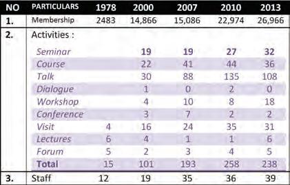
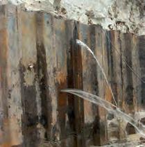
The space constraint became critical from 2000. A solution was needed urgently. This was further compounded by the introduction and implementation of the CPD requirements of Registered Professional Engineers by the Board of Engineers, Malaysia in 2003.
With all these, IEM had to organise professional activities and provide better services to its members. The need for more meeting rooms was a critical issue. Due to pressing needs, the Institution had to make a bold decision to find an office building that could cater to its present
and future needs. So the idea of having another building was conceived and developed.
THE SEARCH
The idea of acquiring a piece of land from the government to build another IEM building was mooted as early as 1984, with the objective to build an IEM complex.
Following this, the Ad-Hoc Committee on Developing Institution Land was formed. At a meeting on 31st December 1992, the committee had proposed a plan for the IEM Complex. Over the years, the committee had considered several locations, without much success.
In order to refocus the search, it was decided, at a meeting in 2002, to change the name of the Ad-Hoc Committee to Ad-Hoc Committee on Acquisition of IEM Land/Building, with the main role of identifying a suitable building/land within the Klang Valley to be acquired by the institution. From 2002, greater effort was made to identify potential sites. Over the years, about 10 locations were considered but found to be unsuitable for our purpose. Among these were:
a) Land in Sri Muda, Selangor
b) Land in Kelana Jaya (Section SS 5D, Petaling Jaya)
c) APMC building at Jalan Tandang 204. Petaling Jaya.
Some of the reasons for rejecting these locations were:
a) The land was too far from Bangunan Ingenieur
b) Poor access, parking facilities and build up area
c) The price of the property.
In early 2007, the idea to buy the building opposite Bangunan Ingenieur, came quite by chance. It was raining one evening in early March 2007 and three members of the Ad-Hoc Committee on Acquisition of IEM Land/Building members – Datuk Prof. Ir. (Dr) Ahmad Zaidee Laidin, Datuk Ir. Prof. Dr Ow Chee Sheng and Dato’ Ir. Hj. Abdul Rashid bin Maidin – were seeking shelter at the entrance to Bangunan Ingenieur. They had earlier visited another potential site.
As they stood there, they noticed a 4-storey building across the road and it struck them that it would be nice if IEM could buy that building. So Dato’ Ir. Hj. Abdul Rashid bin Maidin volunteered to find out more about the building.
By Y.Bhg. Dato’ Ir. Pang Leong Hoon
At the following meeting in mid-March 2007, Dato’ Ir. Hj. Abdul Rashid bin Maidin told the Ad-Hoc Committee that through his friends, he was able to obtain the relevant information about the property. The property was actually not available yet in the market. It could only be purchased through private treaty. The registered owner was Messrs. Tenggara Plaza Sdn Bhd and the land was charged to Malayan Banking Berhad.
The building was considered very suitable for the IEM’s requirements because of the following:
a) Close proximity: It was just across the road from Bangunan Ingenieur
b) There was sufficient floor area
c) The building was in good condition.
The questions that remained to be considered were the purchase price and the conditions of payment.
THE BUILDING
At long last, the search was over and a suitable building had been found. It was also most timely that the property was available. We could not have been more fortunate.
Details of the building as presented to the IEM Council were as below:
• PRIME STAND-ALONE BUILDING WITH LAND MEASURING 28,797 SQUARE FEET AT LOT 190, JALAN SELANGOR , PETALING JAYA FOR SALE
Property type
Location Neighbourhood
Land area
Built up area
Tenure
Asking Price
Remarks
4-storey + Mezzanine floor.
37 parking bays available within the building’s vicinity Directly opposite Bangunan Ingenieur (IEM), Bangunan Juruukur (ISM) and Hotel Newton of Jalan 52/4. The subject building is located at Jalan Selangor and adjacent to a Shell petrol station (Lot 181) and Lot 179 (which belongs to UDA)
Within the vicinity of Menara Choy Fook Onn, MBPJ Tower, amenities such as the Post Office and the National Registration Department.
28,797 sq ft
36,588 sq ft
99 years (expires in the year 2062)
RM16,000,000.00/= (Malaysian Ringgit: Sixteen Million Only)
Tenanted for 2 years, expiring in the year 2008.
Current tenant is paying RM100,000 per month
The premise then housed the ICHS Nursing College and the immediate lot next to this college was a hotel that belonged to UDA. The building had a Net Lettable area of 30,541 square feet.
Generally in a good state of decorative repair, the property had provision for 50 car park lots around and within its premises. The building included two large auditoriums, many small lecture rooms, theatres, library and ground floor which served as administration offices as well as other open spaces. Other facilities suitable for colleges and academic and educational institution were readily available. It had a good office for big institutional use.
With all the details in hand, the Ad-Hoc Committee on Acquisition Land/ Building then made a proposal to the Standing Committee on Finance and to the Excomm for its consideration in April 2004.
..... to be continued
Back-analyses of Slope Failures to Derive Strength Parameters in the Ground
By Ir. Yee Thien Seng
Ir. Yee Thien Seng is the Chairman for Geotechnical Engineering Technical Division. In 1994, he set up his own practice, Geo. Consult, to support the construction industry with both expert and specialist consultancy, in particular on geotechnical engineering aspects. He has authored/co-authored more than a dozen technical papers in local and international conferences. Ir. Yee is an expert witness and accredited checker for design of geotechnical engineering works registered with the Board of Engineers Malaysia.
The current state of knowledge in the engineering fraternity has undoubtedly been developed through destructive testing of engineering elements.
Engineering systems are frequently evaluated in miniaturised dimensions and the outcomes then extrapolated and scaled up to life-sized constructions. Prototype tests to failure have also been undertaken but they tend to be few and far between, owing to time and cost considerations.
So whenever a real-life construction failure occurs, engineers will grasp at the opportunity to treat it as a prototype scale test and subject it to back-analyses (forensic engineering activities) to unravel the governing cause for the distress as well as attempt to push back the frontiers of knowledge. This will include the estimation of material strengths prevailing at the instance of failure.
Earthworks engineering is no exception. It has had its share of such treatment as seen in Bjerrum (1972) and Skempton (1964). These two landmark publications marked the emergence of serious efforts at attempting to understand the likely operational strengths in the ground at the instant of structural failure.
In particular, Skempton (1964) demonstrated, from a very long time back, that mobilisable shear strengths during slope failures were less than peak values obtained from element tests on soil samples in the laboratory. Likewise, Bjerrum (1972) also showed that peak undrained shear strengths were not available in soft ground foundations supporting embankments.
Strengths of materials prevailing in the ground are especially desired when it comes to the design of remedial works following failures of structures that supported the ground.
A deficiency with the evaluation of earthworks structural stability lies with engineering practitioners’ discomfort in reconciling field and laboratory tests with the processes occurring at the instance of a failure. Such deficiencies could not be addressed until
the mechanics of soils founded on effective stress was developed and understood.
Though the considerably more comprehensive framework of critical state soil mechanics was released to the world vide Schofield and Wroth (1968) its acceptance was hesitant at best, even today. This allowed the preservation of a “mystical aura” in geotechnical engineering which sustained the inability to relate elemental tests to field behaviour and encouraged empiricism in geotechnical engineering practice.
This discussion concerns the employment of the back-analyses to derive engineering parameters following failures of earth structures. It is limited to problems of stability owing to gravity forces alone, namely slopes. These may be cut slopes or slopes of embankments built over competent foundations. Such problems involve the least complexities as far as shear strength variation specifications are concerned as opposed to stability evaluations involving soft ground foundations.
A compelling reason to establish reliable strength parameters for use in earthworks engineering analysis and design, lies in the fact that a very low reserve of strength against collapse is targeted. This is despite the rather inexact analysis methods available. The widely adopted guidance GCO (2000) recommends a Factor of Safety (FoS) of only 1.4 in a 10-year return period rainfall for the highest risk-to-life category of earthworks. For slopes deemed to have lesser risk-tolife consequences, the FoS is an even lower 1.2. Such a magnitude of strength reserve against collapse is by far the lowest employed for civil engineering constructions.
When deployed with a set of unrealistic and optimistic shear strength parameters for the ground, the true reserve for stability may be smaller than envisaged or worse, not even in existence. It should be noted that GCO (2000) does not specify what shear strength parameters should be used.
1.0 ANALYSIS METHODS
The Limit Equilibrium Method is the oldest available procedure for the analysis of stability of slopes for design and it is by far the most popular and convenient to use. A second method of greater sophistication and capability is the Finite Element Method. Today, both methods are complemented by very capable preprocessing and post-processing facilities, making them easy to operate. But use of the Finite Element Method is rather limited as it demands a deeper understanding of engineering mechanics and numerical modelling from the user.
1.1 LIMIT EQUILIBRIUM METHOD
The Limit Equilibrium Method (LEM) utilises the principle of static equilibrium and computes the FoS provided by the resisting capacity of the ground against the destabilising gravity forces. The problem geometry is divided into a pre-selected number of slices and the collective static equilibrium evaluated for each pre-defined analysis geometry. A large number of geometries has to be dealt with in order to arrive at the likely FoS for a particular problem, the lowest computed FoS being the one of interest.
There is a large number of LEMs available and most of these have been incorporated into software codes and available commercially. The principal differences between the various methods lie in whether stability is evaluated using moment or force equilibrium or both, as well as in the way the inter-slice forces are addressed. Solutions based on moment equilibrium are less affected by inter-slice forces assumptions. Naturally, varying results will arise from the different LEMs used for an identical problem. The more comprehensive methods satisfy both moment and force equilibrium together with the treatment of inter-slice normal and shear forces included.
But the LEM solution can be fraught with inadmissible physics particularly associated with the treatment of side shear forces on the sides of slices while still providing a seemingly reasonable answer. Whitman & Bailey (1967) discusses this problem in great detail and concedes that ground with multiple soil stratifications will make it very difficult to evaluate the validity of a LEM analysis.
1.2 LEM SUPPLEMENTED WITH STRESS ANALYSIS
A hybrid procedure is promoted in Krahn (2003) where the normal stresses at the base of slices are predetermined from a finite element analysis and then imported for use with the LEM.
This offers the advantage of capturing the relevant kinematic features of a problem along with a more representative distribution of stresses along a shearing surface, thereby allowing the LEM to arrive at the solution with a larger lower bound. As the stresses are obtained from a continuum analysis, it obviates the need to arbitrarily specify inter-slice side force functions and therefore, relieves the need to check for validity of the location of the line of thrust on each slice.
Krahn (2003) suggested that even the use of the simplest linear elastic material model with the gravity turn-on technique applied after the creation of the problem geometry, would be sufficient to allow the LEM to yield a superior analysis. His examples of computations employing stresses imported from finite element analyses, all showed higher FoS than those made solely from LEM analyses, as would be expected.
But it should be cautioned here that there exists the danger of erroneously high lower bound solutions resulting from unrealistic
stress analyses especially where material stratifications with very large stiffness differences are present.
1.3. FINITE ELEMENT METHOD
The forte of the Finite Element Method (FEM) in an engineering analysis lies in its ability to compute deformations. It is able to couple with highly refined constitutive stress-deformation soil models to accomplish this. To arrive at the FoS against failure used in the same context as the LEM, the shear strengths in the modelled ground are reduced progressively until failure is obtained in the analysis. Zienkiewicz et al. (1975) offered the first publication on this procedure. The smallest reduction factor that results in failure is then declared the FoS.
While the FEM offers a number of advantages over the LEM in terms of realism with stress analysis, it does require more input descriptors than the latter and makes the former more formidable to conduct. Griffiths and Lane (1999) gives a good account of the technique. Stress and deformation compatibility is assured throughout the body of the problem being evaluated. Its validity will be greatly dictated by the choice of material stress-strain model(s) used and whether the geological and constructional processes that lead to the formation of the ground geometry being evaluated have been reasonably replicated.
Structural failure in FEM analysis is commonly taken to occur when the analysis is unable to converge to a solution. But as Krahn (2003) pointed out, the FEM analysis may display the inability to converge for reasons other than structural failure, so the method can readily lend itself to spurious outcomes.
In the back-analysis on a slope collapse, the FEM analysis has to start with the problem already with the non-convergence condition so it will not be able to yield a valid set of stress distribution results for use in the hybrid LEM analysis. This leaves the conventional LEM available for back-analysis.
2.0 THE BACK-ANALYSIS
The analysis for determining the structural stability of any earthworks construction is mostly made using the limit equilibrium approach. This would require the following input parameters to be known for a particular ground geometry, namely, 1. cohesion, c’
2. soil friction angle, φ’
3. bulk density, γ
4. pore-water pressure,u w
In a back-analysis of a collapsed slope, this would mean the need for 4 basic variables to be specified for each soil stratification. The strength parameters sought usually are c’ and φ’ though in rare instances, the water pressure regime is sought (MPAJ, 1994). They can exist in many very significant permutations especially when multiple soil stratifications are present.
The back-analysis process is invariably made by invoking the FoS of the failed construction as unity and then iteratively determining the parameters that collectively satisfies this. As previously noted, the back-analysis is not likely to enjoy the availability of a set of stresses from a prior FEM analysis.
In routine design application, being a Lower Bound class of solution, the LEM produces a conservative estimate of stability for the strength parameters used. So a back-analysis employing this procedure will yield a set of higher strength parameters than may actually prevail in the ground at collapse.
Chandler (1977) reported back-computed values of up to 10% higher than laboratory test values in spite of working with the “maximum observed pore water pressures”. His laboratory test strengths were the residual values to reflect observed the landsliding on pre-existing shear surfaces.
3.0 MATHEMATICAL VALIDITY OF BACK-ANALYSIS
Any back-analysis, by whatever means on a single failure geometry, amounts to little more than an attempt at solving a single mathematical equation. This naturally permits no more than just a single unknown quantity to be solved for whenever a back-analysis is conducted.
In most cases, each slope failure involves construction with the same single geometry. This affords just a single back-analysis to be conducted when a failure occurs. The same is likely to prevail with landslides in natural slopes, commonly taking the form of reactivated slides.
(Reg. : 372711-D
(Reg. : 952175-T )
5, Jalan Pemberita U1/49, Temasya Industrial Park, Glenmarie, 40150 Shah Alam, Selangor, Malaysia. Tel: +603-5569 3698 Fax: +603-5569 4099
Leroueil and Tavenas (1981) advocated that failures in the same ground, with as many different geometries as possible, must be analysed in order to arrive at a set of valid strength parameters for the ground. But they still expressed doubts as to the accuracy of the back-analysis since exact pore water pressure conditions at the instant of failure and, in particular, its variation along the failure shear surface, was unknown. They further stated that a back-analysis cannot be reliable when some key input data to the analysis has to be explicitly assumed which invariably is unavoidable for most instances.
Chandler (1977) cautioned that the outcome from a back-analysis can only be validly used when the data is used in the subsequent analysis where the geometry of the landslide being analysed is not radically changed by the ensuing remedial engineering works. Further, considering that different LEMs will give rise to different results, the back-analysed strengths should only be subsequently used with the same LEM that was employed to obtain them. The implication of this assertion is the risk of over-estimation of FoS in remedial designs, an undesired consequence.
In most real life situations, the final state of the collapsed slope usually comprises the aggregation of a number of retrogressive failures and each stage of failure will have a different pore water pressure regime associated with it. This makes it close to impossible to establish the representative slope geometry and pore water pressure regime to be used in the back-analysis for any stage.
4.0 CONCLUSION
The commonly employed LEM of stability analysis, being a lower bound solution, leads to overly-optimistic evaluated shear strength parameters when used in the back-analysis of earthworks failures.
Back-analysis of earthworks structural failures cannot generally claim validity as a procedure to obtain geotechnical engineering parameters for subsequent engineering design work to supplant laboratory tests on soil specimens carried out under appropriate testing parameters.
The use of shear strengths derived from the back-analysis of a failed slope may lead to the design of remedial works appearing more generous than they may really be.
REFERENCES
[1] Bjerrum, L. (1972). “Embankments on soft ground.” Proceedings of the ASCE Specialty Conference on Performance of Earth and Earth-Supported Structures, Lafayette, Indiana, Vol. II, pp. 1-54.
[2] Chandler, R.J. (1977). “Back analysis techniques for slope stabilisation works: a case record.” Geotechnique 27, No. 4, pp. 479-495.
[3] GCO (2000). “Geotechnical manual for slopes.” Geotechnical Control Office, Hong Kong.
[4] Griffiths, D.V. and Lane, P.A. (1999). “Slope stability analysis by finite elements.” Geotechnique 49, No. 3, pp. 387-403.
[5] Krahn, J. (2003). “The 2001 R.M. Hardy Lecture: The limits of limit equilibrium analysis.” Canadian Geotechnical Journal 40, pp. 643-660.
[6] Leroueil, S. and Tavenas, F. (1981). “Pitfalls of back-analyses.” Proceedings of the 10 International Conference on Soil Mechanics and Foundation Engineering, Stockholm, pp. 185190.
[7] MPAJ (1994). “Report of the Inquiry Committee into the collapse of Block 1 and the stability of Blocks 2 and 3 Highland Towers Condominium, Hulu Klang.” Report of the Technical Committee of Investigation.
[8] Krahn, J. (2003). “The 2001 R.M. Hardy Lecture: The limits of limit equilibrium analysis.” Canadian Geotechnical Journal 40, pp. 643-660.
[9] Leroueil, S. and Tavenas, F. (1981). “Pitfalls of back-analyses.” Proceedings of the 10 International Conference on Soil Mechanics and Foundation Engineering, Stockholm, pp. 185-190.
[10] MPAJ (1994). “Report of the Inquiry Committee into the collapse of Block 1 and the stability of Blocks 2 and 3 Highland Towers Condominium, Hulu Klang.” Report of the Technical Committee of Investigation.
[11] Schofield, A.N. and Wroth, C.P. (1968). “Critical state soil mechanics.” McGraw-Hill: London.
[12] Skempton, A.W (1964). “Long term stability of clay slopes.” Geotechnique 14, No. 2, pp. 77-101.
[13] Skempton, A.W (1970). “First time slides in over-consolidated clays.” Geotechnique 20, No. 3, pp. 320-324.
[14] Whitman, R.V. and Bailey, W.A. (1967). “Use of computers for slope stability analysis.” Journal of Soil Mechanics and Foundations Division, ASCE 93, SM4, pp. 475-498.
[15] Zienkiewicz, O.C., Humpheson, C. and Lewis, R.W. (1975). “Associated and non-associated viscoplasticity and plasticity in soil mechanics.” Geotechnique 25, pp. 671-689.
IEM DIARY OF EVENTS
Title: One-Day Workshop on Learn PHP and MySQL - Start Developing Web Sites Like A Pro! 24th January 2015
Organised by : Information and Communications Technology Special Interest Group Time : 9.00 a.m. - 5.00 p.m.
CPD/PDP : 6.5
Title: 2-Day Symposium/ Workshop on Presentation and Reviewing of the Draft Malaysian N.A. for EC8 09th-10th Feb 2015
Organised by : Civil and Structural Technical Division with IEM TC on Earthquake Time : 9.00 a.m. - 5.00 p.m.
CPD/PDP : 16
Kindly note that the scheduled events below are subject to change. Please visit the IEM website at www.myiem.org.my for more information on the upcoming events.
Institusi mengucapkan terima kasih kepada semua yang telah memberikan sumbangan kepada tabung Bangunan Wisma IEM. Ahli-ahli IEM dan pembaca yang ingin memberikan sumbangan boleh berbuat demikian dengan memuat turun borang di laman web IEM http:// www.iem.org.my atau menghubungi secretariat di +603-7968 4001/5518 untuk maklum,at lanjut. Senarai penyumbang untuk bulan Januari 2015 adalah seperti jadual di bawah:
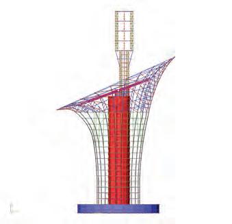
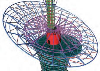
Key features of Scia Engineer: Use your Design Competence and Know-How Worldwide Integrate your Design Process and Reduce your Investments Streamline the Cooperation within the Design Team through BIM Look for New Challenges in your Field Make your Design Environmental and Economical
References: MC Hee & Associates, AC Haimi Jurutera Perunding, Vasco Scaffold Sdn.Bhd. , Perunding ZNA (Asia) Sdn. Bhd., SNA Consult Sdn. Bhd., Ir. Tan K.Y.,Universiti Putra Malaysia. For more information please contact:
W-5-3, Subang Square Business Centre Jalan SS15/4G 47500 Subang Jaya SELANGOR DARUL EHSAN
Tel: +603-5634 7905 / 016-2223685
Fax: +603-5637 9945
Website: www.apptechgroups.net
Email: admin@apptechgroups.net.
www.nemetschek-scia.com
Instrumented Low Embankment on Stone Columns for the Ipoh-Padang Besar Double Tracking Project
of the IEM Geotechnical Engineering Technical Division (2005- 2008).
P.V.S.R. Prasad is currently the Senior Geotechnical Engineer of Keller (M) Sdn. Bhd. He obtained his bachelor degree in Civil Engineering from Andhra University in Visakhapatnam, India and Master of Technology in Geotechnical and Geoenvironmental Engineering from Indian Institute of Technology in Delhi, India.
Ir. Dr Ooi Lean Hock
Ir. Dr Ooi Lean Hock graduated with PhD in geotechnical engineering from the University of Sydney, Australia. He has worked as a geotechnical consultant and as a specialist contractor. He is currently the Head of Geotechnical in the Design & Technical Department of MMC GAMUDA KVMRT (T) Sdn. Bhd. for the Klang Valley Mass Rapid Transit from Sg. Buloh to Kajang Line.
Jonathan Daramalinggam
Jonathan Daramalinggam graduated from the National University of Singapore with Bachelor’s and Master’s degrees in Civil Engineering. His professional interests include ground improvement in soft soils and advanced geotechnical modelling. He is currently Corporate Services Manager with Keller Asia.
In Malaysia, pile load test settlement criteria are normally based on JKR’s Standard Specification for Piling Works. The criteria recommended by JKR are as follows:
The Malaysian Transport Ministry had appointed MMC-Gamuda JV to construct 329km of railway line from Ipoh, Perak to Padang Besar, Perlis. The project, including the installation of double tracks, electrification work, construction of bridges, road-over bridges, stations and tunnels, cost over RM12 billion.
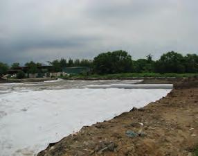
Various ground improvement techniques were employed in the course of the project, including driven piles, installation of prefabricated vertical drains and removal and replacement of soft soils. Among the ground improvement techniques used was Vibro stone columns.
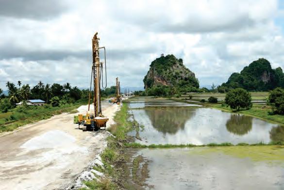
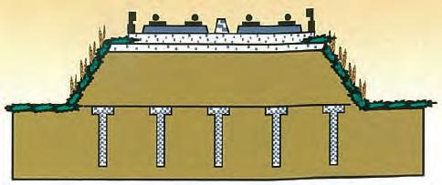
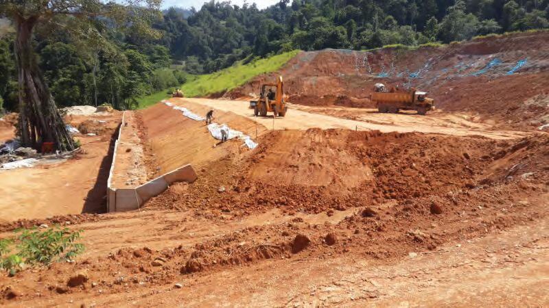
An instrumented low embankment (consisting of two zones, 2m high-5m x 10m and 4m high-25m x 15m, including working platform) was constructed in Kodiang, Kedah, with the following objectives:
a) To see if the use of stone columns for low embankments would result in hard-points (the so-called “mushroom effect”) on the embankment surface.
b) To determine if the design “rest periods” for the surcharge were adequate Confirming the absence of the “mushroom effect” was important because, if it happened, it would require the use of geosynthetics or a thicker load transfer layer.
Determining the correct rest period was important for planning the construction schedule and the amount of earth to be used as a surcharge - both critical factors in a large railway project with stringent performance requirements.
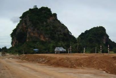
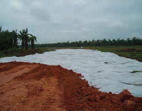
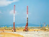
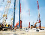
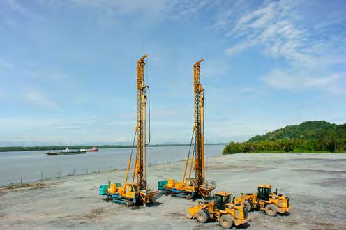
A photograph of the site is shown in Picture 1, while Picture 2 shows the constructed test embankment.
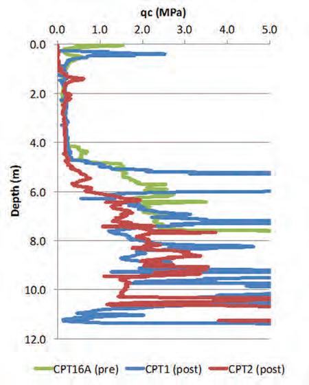
SOIL CONDITIONS
Prior to stone column installation and embankment construction, a dynamic penetration test and a cone penetration test (CPT) were carried out. After the installation of stone columns, two additional CPTs were performed. The CPT plot, shown in Figure 1, was consistent with nearby boreholes.
Based on the CPT and taking into account nearby boreholes, the soil was idealised in Table 1.
The correlations between undrained shear strength and constrained modulus were based on past experience in Malaysia and was consistent with other published data such as Duncan & Buchignani (1976).
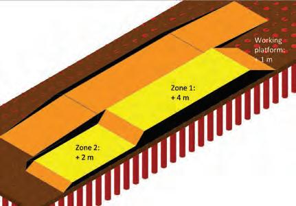
STONE COLUMN LAYOUT AND EMBANKMENT GEOMETRY
For settlement analyses, apart from the design dead load of the embankment (Hgross x 20 kN/m3) and the ballast (Hgross x 22 kN/m3), an additional 12.5 kPa was assumed over the width of the ballast. (Live loads were only assumed for stability analyses, which were beyond the scope of this paper.)
Priebe’s (1995) method was used to estimate total settlements. Based on an embankment height of 4m (1m working platform, 2m permanent fill, 1m surcharge), the total settlements were estimated
P.V.S.R. Prasad
Ir. Yee Yew Weng
Ir. Yee Yew Weng is currently the director of Keller ASEAN. He is the Secretary General of the Malaysian Geotechnical Society. He was past Chairman
Photo 1: Photograph of test location
Photo 2: Photograph of completed test embankment
Settlements assumed negligible. Borehole data indicates SPT N values from 11 to 14, CPT indicates qc values greater than 1.5 MPa
4 > 13.0 Limestone Settlements assumed negligible. SPT hammer rebound. RQD values between 50% and 100%.
at 250mm, with a 2.2m x 2.25m square grid. The design length of the columns was 6m.
The layout of the stone columns and test embankment is shown in Figure 2.
The track was required to have a maximum total settlement of 25mm over six months from start of service. Differential settlement was to be limited to 10mm over a length of 10m. (While the performance criteria also required minimum factors of safety against slope stability, only settlement performance would be discussed in this article.)
STONE COLUMN INSTALLATION, INSTRUMENTATION AND EMBANKMENT CONSTRUCTION
First, a 1m-thick working platform was constructed using sand. The working platform was constructed in mid-May 2008. Then Vibro stone columns were constructed using the dry bottom-
feed method of construction. The columns were installed in a grid below and beyond the embankment. For the 72 columns installed directly under the embankment, the average depth of the columns was 6.0m.
Key events are listed below:
• 10th to 31st May 2008. Construction of 1m working platform
• 1st week June to 1st week July 2008. Installation of Vibro stone columns
• 17th Nov 2008. Start of instrument installation
• Feb 2009. Start of embankment construction
• 2nd Sept 2009. End of embankment construction. Start of rest period.
• 31st March 2010. End of monitoring, removal of trial embankment
A variety of instruments were installed, including rod settlement gauges, surface settlement markers, total stress cell, extensometers, piezometers and ground heave markers. Due to the quantity of data collected, only some of the results from Zones 1 and 2 were presented and discussed.
PREDICTION OF SETTLEMENTS AND CONSOLIDATION RATE FOR 4M EMBANKMENT (ZONE 1)
Initially, using parameters from Table 1, and based on a total fill height of 4.1m, Priebe’s (1995) method was used to estimate total settlements, with a prediction of 250mm. The 4.1m included the 1m-thick working platform. However, as Table 2 indicated, there was a lapse of 7 months (July 2008 to February 2009) between the installation of the stone columns and the start of embankment construction. During this time, no settlement measurements were taken, meaning the settlement resulting from the 1m working platform was not recorded.
The theoretical period for 90% degree of consolidation from the working platform load was 3 months, calculated by Balaam & Booker’s (1981) method. As the elapsed period was 7 months, we were confident that little or no settlement coming from the 1m working platform remained, when the embankment construction and monitoring started in February 2009.
As the embankment fill was placed progressively, the rate of settlement was estimated based on Han & Ye’s (2001) method. Key input parameters include an assumed stress ratio (stress concentration on column) n = 3 and consolidation parameters indicated in Table 1. Settlement magnitudes were taken out of the Priebe analysis.
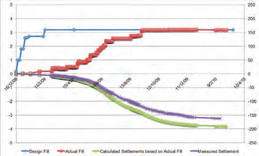
The plot of fill height, settlement (average measurements from rod settlement gauges 1 to 6) and time are shown in Figure 3.
Figure 1: Cone penetration test results
Figure 2: Three-dimensional view of stone column layout under test embankments
Table 1: Idealised soil profile
As can be seen, actual filling took much longer than initially assumed at the design stage. Because of this, the same soil parameters were taken (Table 1), but the actual filling rate was used in a back-analysis. The results are also shown in Figure 3.
Based on the actual loading magnitude (3.2m of fill measured from the top of the working platform) and filling rate, the total long-term settlement was estimated at 197mm. Theoretically, 90% degree of consolidation would be reached 2 months after completion of filling. Observed settlements at the end of the trial was 163 mm (March 2010). 90% of these settlements (i.e. 147mm) were observed at about 2.5 months after completion of filling. Both magnitude of settlements and rate of consolidation were reasonably well predicted by the simple analytical methods employed.
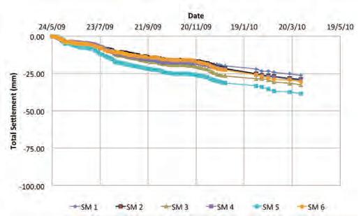
OTHER OBSERVATIONS AT ZONE 2
Figure 4 shows that Zone 2 surface settlement markers (SM1 to SM6) placed directly over the columns and in between the columns, indicated no differential settlement. Visually too, “hard points” were not observed on this test embankment, in spite of Zone 2 being only filled to little over 1m height, over the working platform. In reality, this observation is unsurprising, seeing that stone columns are relatively ductile elements and tend to bulge laterally when loaded.
CONCLUSION
From this test embankment, we were able to conclude the following:
• With appropriately selected input parameters, Priebe’s (1995) method adequately predicted the total settlements resulting from these low embankments.
• Similarly, Han & Ye’s (2001) method adequately predicted the rate of settlements.
• No “hard points” were observed, either from settlement markers or visually
The test embankment was taken down in April 2010. Since then, the actual railway embankments had been completed. In April 2013, MMC-Gamuda handed over the completed embankment and track to the authorities and the track was opened to commercial rail traffic from June 2013. No performance issues have been raised to date.
In addition, data from settlement markers installed in March 2012 indicated that the embankment was performing as expected. In the first 6 months since the track was operational
(June 2013 to December 2013), the surface settlement markers closest to the test area showed a settlement of 4-5mm, below the allowed values, confirming the effectiveness of the stone column solution.
REFERENCES
[1] Balaam, N. P., Booker, J. R. (1981),“Analysis of rigid raft supported by granular piles”, International Journal for Numerical and Analytical Methods in Geomechanics 5, pp. 379-403
[2] Duncan, J.M. & Buchignani, A.L., 1976, “An Engineering Manual for Settlement Studies”, University of California, Berkeley
[3] Han, J. and Ye, S. L. (2001),“A simplified method for computing consolidation rate of stone column reinforced foundations”, Journal of Geotechnical and Geoenvironmental Engineering, ASCE, 127(7), pp. 597-603.
[4] Priebe, H.J. (1995), “The Design of Vibro Replacement,” Ground Engineering, December 1995, pp. 31-37.
IEM DIARY OF EVENTS
Title: International Conference & Exhibition on Tunnelling & Underground Space 2015 (ICETUS 2015) Sustainable Transportation In Underground Space Development
3rd – 5th March 2015
Organised by : IEM Training Centre with Tunnelling and Underground Space Technical Division Time : 9.00 a.m. – 5.00 p.m.
CPD/PDP : For information, please visit the IEM website
Title: Myths & Common Problems in Geotechnical Forensic Engineering
12th Jan 2015
Organised by : Civil and Structural Technical Division with IEM TC on Earthquake Time : 5.30 p.m. – 7.30 p.m.
CPD/PDP : 0
Kindly note that the scheduled events below are subject to change. Please visit the IEM website at www.myiem.org.my for more information on the upcoming events.
Figure 3: Settlement results from rod settlement gauges, measured and calculated (Zone 1)
This course will provide participants with a broad understanding of the LNG industry, the LNG value chain, and an approach to FLNG (Floating Lique ed Natural Gas) eld development planning. This includes a review of the fundamentals of naval architecture, hull design, and LNG containment systems for FLNG facilities. The course will also cover the marine engineering discipline, gas receiving, pre-treatment and liquefaction processes, o oading of LNG and regasi cation processes, operational challenges and technical risks, and nancial and contracting strategies for FLNG and FSRU (Floating Storage & Regasi cation Unit) projects. Aspects of the Shell Prelude FLNG and PETRONAS PFLNG will be shared. The objective is to provide participants with a strategic overview covering both technical and commercial knowledge, which will enable participants to make informed decisions and help them in planning their respective FLNG and FSRU projects.
contract, commercial and procurement | discipline engineering | eld development | health, safety, environment and quality | o shore engineering o shore marine & shipbuilding | onshore plants | project management
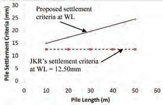
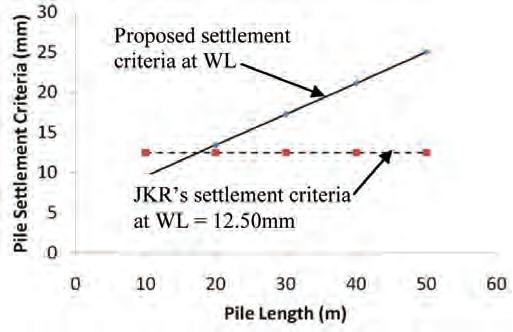
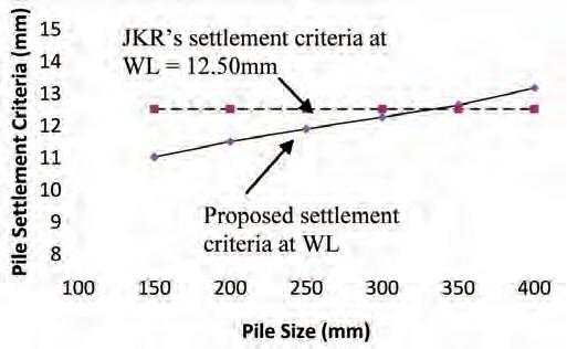
Rationalised Settlement Criteria for Pile Load Test
Ir. Chow Chee Meng is currently the Director of G&P Geotechnics. He was a committee member of the Geotechnical Engineering Technical Division of the IEM from 2008 to 2013.
By Dato’ Ir. Dr Gue See Sew
Dato’ Ir. Dr Gue See Sew was the President of IEM from 2001 to 2003. He is also a Fellow of the Academy of Sciences Malaysia and currently the Chief Executive Officer of G&P Professionals Group.
In Malaysia, pile load test settlement criteria are normally based on JKR’s Standard Specification for Piling Works. The criteria recommended by JKR are as follows:
Apile tested shall be deemed to have failed if (JKR, 1988):
i. The residual settlement after removal of the test load exceeds 6.50mm
ii. The total settlement under the Working Load exceeds 12.50mm
iii. The total settlement under twice the Working Load exceeds 38.0mm, or 10% of pile diameter/width whichever is the lower value.
The criteria given by JKR have served the industry well since its introduction but the settlement criteria may produce difficulties in situations where relatively long or large diameter piles are adopted. This is because the elastic compression of long or large diameter piles is signficant and very often, the elastic compression recorded during pile testing exceeds the recommended criteria specified by JKR. This may result in unrealistic design if the criteria recommended by JKR are strictly imposed.
In addition, strict adherence to the requirements of total settlement under twice the Working Load not exceeding 38.0mm, or 10% of pile diameter/width whichever is the lower value will also result in unduly conservative pile design. This is because pile is traditionally designed to global Factor of Safety (FOS) of 2.0 which means the pile is expected to fail with excessive settlement much larger than 38mm at twice the Working Load.
Therefore, if the pile settlement under twice the Working Load is within JKR’s settlement criteria, it means that the pile FOS is more than 2.0! This also applies similarly to criterion on residual settlement.
In this paper, some comparisons of settlement criteria of other countries and published literatures are made and rationalised settlement criteria for pile testing are proposed based on the on the experiences of the authors and results of recent research.
SETTLEMENT/FAILURE CRITERIA FOR PILE LOAD TESTS
Table 1 summarises some of the settlement/ failure criteria for pile load tests from different countries and published literatures extracted from Ng et al. (2004) and which are further updated in this paper by the Authors.
From the table, it can be observed that recent publications have indicated the importance of including pile elastic compression in determining settlement criteria for pile load tests. Some examples include:
a) Federation of Piling Specialists, FPS, UK (2006)
For insensitive buildings:
Pile settlement at DVL, ∆M < 10mm + PL/AE for piles less than 1000mm diameter.
Where:
P - load on pile
L - pile length
A - cross-sectional area of pile
E - elastic modulus of pile
DVL is the working load plus allowances for soil induced forces such as downdrag or heave, and any particular conditions of the test such as variation of pile head casting level.
For test piles greater than 1000mm diameter a value in excess of 10mm may be appropriate. Maximum settlement at loads greater than DVL should not be specified for insensitive buildings.
b) Housing Authority, Hong Kong Special Administrative Region (HA)
Pile settlement, ∆M < PL/AE + D/30 (in mm) ∆Rf <D/50 or 10mm whichever is smaller ∆Rb < D/100 or 5mm whichever is smaller where ∆Rf is the residual settlement for pile embedded in soil, ∆Rb is the residual settlement for pile bearing on rock.
Furthermore, BS8004: 1986, Clause 7.5.6.5 also highlights that the ultimate bearing capacity of the pile may be taken as the force at which the penetration is equal to 10% of the diameter of the base of the pile but elastic
By Ir. Chow Chee Meng
shortening will need to be taken into account for very long piles. This is because the elastic shortening of the long pile itself may reach 10% of the base diameter.
As such, from a review of current practices worldwide, it is demonstrated that there is a need for Malaysian settlement criteria for pile load tests be updated.
PROPOSED SETTLEMENT CRITERIA FOR PILE LOAD TEST – BORED PILES
The proposed settlement criteria for pile load test for bored piles are based on Ng et al. (2004) where test piles range from 0.6 to 1.8m in diameter and from 12 to 66m in length are used in establishing the proposed criteria.
STUDY OF PILE TOE MOVEMENT FOR BORED PILES
In order to establish suitable settlement criteria for failure load, studies on the toe resistance-movement relationships have been carried out and the results are summarised in Figure 1. From Figure 1, it can be seen that the full mobilisation of toe resistance is difficult to achieve, as it may require extremely large toe movements. However, a moderately conservative movement for the mobilisation of toe resistance has been identified to be 4.5% of pile diameter (d), and this is consistent for both piles founded on residual soils and piles founded on weathered rocks (Ng et al. (2004)).
STUDY OF SHAFT SHORTENING FOR BORED PILES
In some of the settlement criteria summarised in Table 1 (e.g. Davisson criteria and FPS Method), pile shaft shortening equal to PL/AE is included in determining allowable settlement. The assumption made is that no frictional resistance acts along the whole pile length. However, the magnitude of pile shaft elastic shortening is less than PL/AE due to resistance from the soil. Measurement carried out by Ng et al. (2001) – Figure 2 shows
that the elastic compression is less than PL/AE and a moderately conservative estimate of shaft shortening are as follows:
a) For piles founded in soil, Elastic shortening = ½ PL/AE
b) For piles founded on rocks and/or with rock sockets and for piles with slip liners Elastic shortening = ¾ PL/AE
In order to propose appropriate settlement criteria for pile load test of bored piles, the design approach generally adopted in Malaysia for design of bored piles is briefly discussed below.
DESIGN
OF BORED PILES – MALAYSIAN PRACTICE (TAN & CHOW, 2003)
In conventional bored pile design practiced in Malaysia, the Factors of Safety (FoS) normally used in static evaluation of pile geotechnical capacity are partial FoS on shaft (Fs) and base (Fb) respectively; and global FoS (Fg) on total capacity. The lower geotechnical capacity obtained from both methods is adopted as allowable geotechnical capacity
Note: Use the lower of Qag obtained from eq. 1 and eq. 2 above. BS8004:1986, Clause 7.3.8 also states that:
“In general, an appropriate Factor of Safety for a single pile would be between two and three. Low values within this range may be applied where the ultimate bearing capacity has been determined by a sufficient number of loadings tests or where they may be justified by local experience…”
Similarly, American Society of Civil Engineers (ASCE), 1993 also recommends a minimum global factor of safety of 2.0 for compression pile where the pile capacity is verified by a sufficient number of load tests on preliminary piles.
Figure 1: Toe resistance-movement relationships for (a) piles embedded in saprolites; (b) piles socketed in and founded on weak rocks (after Ng et al., 2001).
Figure 2: Pile shaft shortening (after Ng et al., 2001).
(eq.1)
(eq.2)
As such, bored piles are commonly designed to global FOS of 2.0. Therefore, it is acceptable for bored piles to fail when tested to twice the Working Load. Limiting the settlement criteria at twice the Working Load is therefore irrational and leads to unduly conservative design.
CRITERIA ON RESIDUAL SETTLEMENT
Residual settlement criteria as adopted in JKR’s Standard Specification for Piling Works should be reviewed based on the following discussion. Although the residual pile movement may give some indication of soil yield along the shaft and at the pile tip, the magnitude of residual settlement is strongly affected by ‘locked-in movement’ of the pile. This is because the anticipated elastic rebound of the pile may be affected by side shear acting downward against the pile unloading and preventing it from fully recovering the elastic compression.
This locked-in effect cannot be accurately and reliably assessed (Ng et al., 2004). In addition, the residual movement is affected by any creep in the concrete pile. These two phenomena are likely to be more prominent in long and large-diameter bored piles and barrettes than short and smalldiameter driven piles (GEO, 1996; Ng et al., 2001). The residual pile movement criterion is therefore irrational, unreliable and unsuitable for use as an acceptance criterion, especially for long piles and barrettes, and it always leads to unnecessarily conservative design (GEO, 1996).
TEST LOAD FOR WORKING PILES
For working piles, it is adequate to test the pile up to 1.5 times instead of 2.0 times the Working Load. This is to prevent damaging the working piles and is consistent with the recommendations of ICE Specification for Piling and Embedded Retaining Walls (ICE, 2007) where proof test (equivalent to working pile test) is required to be tested up to 100% DVL + 50% SWL which is
equivalent to 1.5 times the Working Load for piles not subjected to downdrag. (Note: Design Verification Load, DVL – working load plus allowances for soil induced forces such as downdrag or heave, and any particular conditions of the test such as variation of pile head casting level, SWL – specified working load). Therefore, the proposed settlement criteria for pile load test for bored piles are as follows:
a) The total settlement at Working Load does not exceed the following magnitude or other suitable magnitude based on structural considerations:
For piles founded in soils:
∆M = 12.50mm + ½ PL/AE
For piles founded on rocks and/or with short rock sockets and for piles with slip liners:
∆M = 12.50mm + ¾ PL/AE
Note: The 12.50mm limit is a conservative limit to ensure that differential settlement between columns of a building will not affect its safety and serviceability. Typically, differential settlement between any two piled foundations is unlikely to be greater than 75% of the maximum settlement (Craig, 1998). As such, for medium-rise to high-rise buildings with column spans ranging from 5.0m to 8.5m where bored piles are typically used, the maximum differential settlement for a 25m long, 1.2m diameter rock-socketed bored pile (Working load = 9800kN) would be approximately equal to 0.75*18.5mm = 14mm.
The distortions due to the differential settlement will range from 1/350 to 1/600 which is within the allowable limits to prevent cracking in walls and partitions of 1/300 and well within the limits for structural damage of 1/150 (Skempton & McDonald, 1956).
In the design of foundations, it is important to control distortions/ differential settlement rather than total settlement. Controlling total settlement in order to reduce distortions/differential settlement will lead to unduly conservative design. Understanding this principle will produce better foundation design and is consistent with international practice where total settlement of high-rise buildings exceeding 100mm has been reported.
Some recorded total settlement of high-rise buildings of more than 40-storey in Germany is shown in Figure 3.
b) The total settlement, at 1.5 times the Working Load, does not exceed the following values:
For piles founded in soils:
∆M = 0.045d + ½ PL/AE
For piles founded on rocks and/or with short rock sockets and for piles with slip liners:
∆M = 0.045d + ¾ PL/AE where d is the pile diameter/size.
Note: The above values were also proposed by Ng et al. (2004) as failure load criterion for large diameter bored piles and barrettes. The 0.045d limit is based on a moderately conservative movement for the mobiliszation of toe resistance (refer to Figure 1).
Criteria on settlement at twice the Working Load and residual settlement are omitted based on the technical justifications discussed earlier. In addition, the test load for pile testing shall be as follows:
a) Working piles – tested up to 1.5 times the Working Load
b) Prel iminary piles – tested up to at least 2.0 times the Working Load or until the test load cannot be sustained.
Figures 4 and 5 illustrate the difference between JKR’s criteria and the proposed criteria for bored piles founded on rock.
Notes:
1. Figure derived using 1200mm diameter bored pile founded on rock
2. Bored pile constructed using Grade 35 concrete.
4. Pile working load = 9800kN.
5. Pile working load is assumed equal to structural capacity of pile.
Notes:
1. Figure derived based on pile length of 25m founded on rock.
2. Bored pile constructed using Grade 35 concrete.
3. Pile working load is assumed equal to structural capacity of pile.
As can be seen from Figures 4 and 5, the proposed criteria are similar to existing JKR criteria for small pile diameter and relatively short pile length. However, with increasing pile length and diameter, the proposed criteria give more rational settlement criteria and will not result in overly conservative design.
PROPOSED SETTLEMENT CRITERIA FOR PILE LOAD TEST – DRIVEN PILES
Based on experience and findings on bored piles, the settlement criteria for pile load test for driven piles is proposed based on similar concept. The difference in load-transfer mechanism between driven piles and bored piles can generally be summarised as follows:
a) Magnitude of shaft friction
The mobilised shaft friction for driven piles is expected to be higher compared to bored piles due to soil displacement during pile installation.
b) Mobilisation of end-bearing resistance
The required pile settlement in order to mobilise end-bearing resistance for driven piles is expected to be smaller compared to bored piles due to compression of soil at pile tip during installation and effect of residual load due to locked-in effect during pile installation. As such, the proposed settlement criteria for pile load test for driven piles are as follows:
a) The total settlement at Working Load does not exceed the following magnitude or other suitable magnitude based on structural considerations:
Figure 3: Observed settlement of buildings in Germany (after Katzenbach et al., 2000 and Franke et al., 2000)
Figure 4: Effect of pile length on pile settlement criteria.
Figure 5: Comparison between JKR’s criteria at 2.0 times the Working Load with proposed criteria at 1.5 times the Working Load.
For piles founded in soils and rocks:
∆M = d/120 + PL/AE + 4.0mm
Notes:
1. The abovecriteria are similar to Davisson (1972) which is widely adopted.
2. The component for elastic compression used is similar to bored piles. However, the actual magnitude of elastic compression is expected to be even smaller compared to bored piles. This is because the shaft friction in driven piles is expected to be higher and so, the elastic compression is reduced due to resistance from shaft friction.
3. The criteria d/120 is consistent with experience in dynamic testing of piles, which is the recommended toe quake, i.e. displacement at which the static soil resistance changes from elastic to plastic behaviour (Goble & Rausche, 1986)).
4. The magnitude of 4.0mm is consistent with the recommendations of Davisson, 1972.
b) The total settlement at 1.5 times the Working Load does not exceed the following values:
For piles founded in soils and rocks:
Notes:
1. The above criteria is based on the assumption that the pile has “failed” when pile top settlement equal to 10% of the pile base diameter which is specified in BS8004 and Eurocode 7.
2. Only half of the elastic shortening component (PL/AE) is conservatively included in the proposed criteria. This is to account for load transfer mechanism which will reduce the elastic shortening of the pile.
Figures 6 and 7 illustrate the difference between JKR’s criteria and the proposed criteria for driven piles in soil.
Notes:
1. Figure derived using 200mm x 200mm RC Square pile with Grade 45 concrete.
2. Pile working load = 450kN
Similar to bored piles, from Figures 6 and 7, it can be seen that the proposed criteria give more realistic settlement criteria especially for long piles exceeding 20m.
SUMMARY
Based on latest international practice, recent research carried out and Malaysian practice in piled foundation design, the following settlement criteria for pile load test are proposed:
a) BORED PILES
The total settlement at Working Load does not exceed the following magnitude or other suitable magnitude based on structural considerations:
For piles founded in soils:
∆M = 12.50mm + ½ PL/AE
For piles founded on rocks and/or with short rock sockets and for piles with slip liners:
∆M = 12.50mm + ¾ PL/AE
The total settlement at 1.5 times the Working Load does not exceed the following values:
For piles founded in soils:
∆M = 0.045d + ½ PL/AE
For piles founded on rocks and/or with short rock sockets and for piles with slip liners:
∆M = 0.045d + ¾ PL/AE
pile settlement
(Note: Figure derived based on RC square pile with pile length of 15m).
b) DRIVEN PILES
The total settlement at Working Load does not exceed the following magnitude or other suitable magnitude based on structural considerations:
For piles founded in soils and rocks:
∆M = d/120 + PL/AE + 4.0mm
The total settlement at 1.5 times the Working Load does not exceed the following values:
For piles founded in soils and rocks:
∆M = 0.1d + ½ PL/AE
The settlement criteria for driven piles can be further refined as there is still some degree of empiricism in the proposed criteria (e.g. 4.0mm value). Further research can be carried out on driven piles to determine more realistic elastic compression of the pile taking into consideration the effect of load transfer to facilitate refinement of the settlement criteria.
Criteria on settlement at twice the Working Load and residual settlement are omitted based on the technical justifications discussed above. In addition, the test load for pile testing shall be as follows:
a) Working piles – tested up to 1.5 times the Working Load
b) Preliminary piles – tested up to at least 2.0 times the Working Load or until the test load cannot be sustained. The proposed settlement criteria are based on technical justifications to prevent unduly conservative design and are consistent with international geotechnical practice.
Figure 6: Effect of pile length on pile settlement criteria.
Figure 7: Effect of pile size on
criteria.
Products
REFERENCES
[1] American Society of Civil Engineers (1993), “Design of pile foundations”, Technical Engineering and Design Guides as Adopted from the US Army Corps of Engineers, No. 1, 97 p.
[2] ASTM D 1143/ D 1143M (2007), “Standard Test Methods for Deep Foundations Under Static Axial Compressive Load”.
[3] British Standard Institution (1986), “BS8004: 1986 British Standard Code of Practice for Foundations”.
[5] Davisson, M.T. (1972), “High capacity piles”, Proc. Soil Mechanics Lecture Series on Innovations in Foundation Construction, American Society of Civil Engineers, ASCE, Illinois Section, Chicago, 22nd March 1972, pp. 81-112.
[6] Federation of Piling Specialists, FPS (2006), “Handbook on Pile Load Testing”.
[7] Franke, E., El-Mossalamy, Y. & Wittman, P. (2000), “Calculation methods for raft foundations in Germany”, In Design Applications of Raft Foundations (ed. J.A. Hemsley), Thomas Telford, London.
[8] Goble, G.G. & Rausche, F. (1986), “Wave Equation Analysis of Pile Foundations WEAP86 Program”, Volume I and II, prepared for the US Department of Transportation, Office of Implementation, Federal Highway Administration (FHWA), McLean, Virginia.
[10] Institution of Civil Engineers, ICE (2007), “ICE Specification for piling and embedded retaining walls”, 2nd Edition, Thomas Telford, London.
[11] Jabatan Kerja Raya Malaysia, JKR (1988), “Standard Specification for Road Works”.
[12] Katzenbach, R., Arslan, U. & Moorman, C. (2000), “Piled raft foundation projects in Germany”, In Design Applications of Raft Foundations (ed. J.A. Hemsley), Thomas Telford, London.
[13] Ng, C.W.W., Simons, N. & Menzies, B. (2004), “Soil-structure Engineering of Deep Foundations, Excavations and Tunnels”, Thomas Telford, London.
[14] Ng, C.W.W., Yau, T.L.Y., Li, J.H.M. and Tang, W.H. (2001), “New failure load criterion for large diameter bored piles in weathered geomaterials”, J. Geotech. & Geoenvir. Engng, ASCE, 127(6), 488-498.
[15] Skempton, A.W. & MacDonald, D.H. (1956). “The allowable settlement of buildings”. Proc. Instn Civ, Engrs, Part 3, No. 5, pp. 727-784.
[16] Tan, Y.C. & Chow, C.M. (2003). “Design & Construction of Bored Pile Foundation”, Proceedings for 2-Days Conference on Geotechnical Engineering, Design & Construction of Pile Foundation: The Malaysian Experience, IEM (Perak Branch) & JKR Perak Darul Ridzuan, Ipoh, Perak, 29-30 September, 2003.
“Wishing All A Happy and Prosperous Chinese New Year”
(1086519-T)
PRESS STATEMENT
SARAWAK COAL MINE EXPLOSION – SAFETY AND PREVENTION MEASURES NECESSARY
The Institution of Engineers, Malaysia (IEM) is concerned over the recent coal mine explosion that occurred at Silantek Quarry, Pantu near Sri Aman, Sarawak on 22 November 2014 where 3 people were killed and 24 injured
The preliminary investigation revealed that the incident was probably caused by a spark from a faulty fan which caused an explosion in the tunnel which is 700 metres long. However at the time of this press statement, the investigation on the incident is still on-going.
Underground mines have a concentration of naturally occurring methane or other flammable gases such as carbon monoxide or hydrogen sulfide. This is especially so for coal mines. These gases accumulate in pockets in the coal and adjacent strata, and will be released when the coal is mined.
The explosions in coal mines are mainly attributed to methane. In modern mines, gas detectors are crucial for such detection and prevention. Combustible gas detectors will give advance warning of a change in concentration that may enter the explosive range. There should be administrative procedures to determine the acceptable limits of gas formation and methods to respond to adverse gas build up such as proper ventilation control or passage way sealing techniques.
IEM feels that a thorough post-incident investigation must be carried out to determine whether the coal mine has implemented the adequate safety and prevention measures such as early gas and fire detection and control system in accordance with standard engineering procedures and the necessary legislative requirements. The investigation shall also include whether the coal mine safety facilities and fire control systems are continuously maintained and records of such maintenance properly documented.
IEM is also concerned whether any safety assessment has been carried out on all electrical equipment especially explosive type fitting. The electrical design standard shall conform to the explosive type fitting requirement under the most hazardous environment. Due to the presence of methane gas in mines, all electrical equipment need to be robust. Such specialized equipment are designed either to contain any explosion within the device, or is designed not to produce sparks with sufficient energy to trigger an explosion. Electrical safety inspection and electrical hazard safety
The Press Statement was published in the following media: (26 Nov 2014)
1) THE STAR (26 Nov 2014) – IEM Calls for Probe Into Mine Blast (Newsprint – Pg 22 and Online Version) Online Version
2) BORNEO POST (26 Nov 2014) – IEM call thorough Investigation http://www.theborneopost.com/2014/11/26/iem-calls-for-thoroughinvestigations/ (25 Nov 2014)
awareness should be carried out regularly by competent personnel.
IEM would like to propose that all contractors and mining operators involved in underground mining activities must adhere to all the requirements of Malaysian Standard MS 2363: 2010 Work in Tunnelling – Code of Practice or its equivalent BS 6164 and the Guidelines on Occupational Safety and Health in Tunnel Construction 1998 published by DOSH. In addition, the relevant authorities should conduct more regular inspection at all coal mines to ensure strict compliance to the safety standards and operational guidelines.
As reported, during the rescue operation, the level of methane was too high and rescue operation was halted. It would seem that the mine ventilation stopped operation and hindered rescue operations. As underground mines are confined and difficult to access, robustness of ventilation system is needed. Alternative measures and contingencies, such as back-up shaft or exhaust ventilation system, should be available for emergency use. The underground ventilation systems should be designed as part of the overall fire response and control protocol. Ventilation should be arranged to be reversible so that emergency responders may approach an underground fire from more than one direction and from the upstream ventilation flow direction.
While it is regretted that the incident has claimed 3 lives, the management of the coal mine concerned must ensure that a proper Emergency Response Plan should be in place and executed immediately upon occurrence of any emergency incident in order to prevent loss of lives and at the same time minimise the damage and injuries.
IEM is of the opinion that a Disaster Prevention Master Plan for Mining Industry should be formulated urgently. IEM with its available resources is willing to assist the Government with the necessary technical advice in the preparation of such master plan and to serve in any safety committee related to mining.
IEM wishes to extend our sympathies and condolences to the families of the victims in the coal mines explosion in Pantu, Sarawak.
Dato’ Ir. Lim Chow Hock President 25
November 2014
3) THE RAKYAT POST (25 Nov 2014) – Probe whether Sarawak Coal Mine Operator Adhered to Safety Measure, says engineering body Online Version
One-Day Short Course on Slope Safety System in Hong Kong
The Geotechnical Engineering Technical Division (GETD) conducted a short-course on slope safety system at Wisma IEM on 8th August 2014. the speaker was Ir. Terence Chan Chun Fai, former deputy Head of the Geotechnical Engineering Office (GEO) of Hong Kong. the workshop session, chaired by Engr. Dr Gue Chang Shin, was attended by 102 participants.
Ir. Chan started the session by saying that landslides had long been a serious problem in Hong Kong which was characterised by hilly terrain, heavy rainfall and dense population. There are many developments built on hillsides. In 1977, the Hong Kong Government set up the Geotechnical Control Office (now called Geotechnical Engineering Office or GEO), to implement a slope safety system. Through the work of the GEO over the years, the landslide risk in Hong Kong has been significantly reduced.
The GEO tackled the problem of slope failures by implementing a comprehensive Slope Safety System in stages. The key strategies in reducing the overall landslide risk in Hong Kong are shown in Figure 1.
Ir. Chan covered the following key areas in the course: Slope Safety System, Landslip Prevention and Mitigation Programme, Landslip Warning System, Landslide Investigation Programme, Geotechnical Control, Emergency System and Public Education.
He said that in implementing a good slope safety system, it is vital to provide input in the early planning stage to identify geotechnical
constraints on land developments. Landslide risk can then be contained by means of geotechnical control and further reduction in risk through stabilisation works and mitigation measures. Furthermore, it is also essential to promote public awareness and response in slope safety through public education, publicity, information services and public warnings.
He also talked about the landslip prevention and mitigation programme (LPMitP) which included the following key areas:
• Improving slope safety standards, technology, and administrative and regulatory frameworks
• Ensuring safety standards of new slopes
• Rectifying substandard Government manmade slopes
• Maintaining all Government man-made slopes and
• Ensuring owners take responsibility for slope safety.
Ir. Chan introduced the concept of a landslip warning system, which incorporated real time rainfall monitoring and forecast, analysis of rainfall and landslide consequences, real time reporting of landslides and emergency services.
The landslide investigative programme consisted of reviews and forensic studies of reported landslides, understanding the causes of landslides and making recommendations. The common contributory factors to slope failures are adverse ground water condition, weak geological materials, inadequate surface drainage provisions, inadequate slope maintenance and leaky water carrying services.
GEO was set up to exercise geotechnical controls over public and private developments to ensure public safety. For private projects, its roles included giving advice on geotechnical constraints, auditing geotechnical design submissions and imposing conditions during development approval. Geotechnical control also included the registration of new slopes and promoting regular maintenance, monitoring
By Engr. Dr Gue Chang Shin
Engr. Dr Gue Chang Shin is a Committee Member of IEM Geotechnical Engineering Technical Division (GETD). Formerly with the Norwegian Geotechnical Institute (NGI) in Norwa, he is now with NGI-G&P in Malaysia.
GEOTECHNICAL ENGINEERING TECHNICAL DIVISION
Key strategies in reducing landslide risk in Hong Kong
the performance of special geotechnical installations as well as serving statutory dangerous hillside orders and statutory drainage orders for leaking services affecting slopes. The geotechnical controls for public projects are relatively similar to those for private projects. To further enhance geotechnical controls, the registration of geotechnical engineers was introduced in 2006. This was to ensure that only qualified and experienced geotechnical engineers undertook geotechnical design and construction supervision.
GEO’s emergency roles include deciding when a landslip warning should be issued or cancelled, maintaining a 24hour service to provide advice to government departments on immediate or potential dangers due to landslides and measures to deal with the situation.
Landslides are classified into different categories based on degree of seriousness, and follow-up works are carried out, including a rescue phase and a restoration phase. Training and drills are conducted to ensure that emergency services personnel are always prepared for any eventuality.
It was highlighted that public education and awareness are vital in maintaining a slope safety system. The strategies of public education include fostering good public understanding of landslide hazards, promoting public response to landslip warnings, enlisting public support in times of serious landslides and reaching out to slope owners. Ir. Chan stressed that public awareness should be nurtured from a very young age. He said public education is far less expensive than engineering works and is effective in combating the landslide threat.
Finally, he said there can never be zero landslide risk and that once risk is detected, prompt response is crucial to minimise the damages.
The course ended with the presentation of an appreciation memento to Ir. Chan by technical division Chairman Ir. Yee Thien Seng.
GETD committee members with the speaker. From left: Ir. Dr Chan Swee Huat, Ir. Liew Shaw Shong, Ir. Terence Chan Chun Fai, Ir. Jack Pan Kok Loong, Ir. Yee Thien Seng and Engr. Dr Gue Chang Shin
Another Milestone to “Engr” Recognition: IEM Signs MoU With Universiti Teknologi Mara (UiTM)
The Institution of Engineers Malaysia (IEM) and Universiti Teknologi MARA (UiTM) signed a memorandum of understanding (MoU) on 18th November 2014 at UiTM Shah Alam.
The MoU was signed between IEM President Y.Bhg. Dato’ Ir. Lim Chow Hock and UiTM Vice Chancellor Y.Bhg. Tan Sri Dato’ Sri Ir. Dr Sahol Hamid Abu Bakar.
Also present were Ir. Prof. Dr Wan Mahmood bin Wan Abdul Majid (IEM Vice President and Chairman of Standing Committee of Admission and Practical Training) Ir. Gunasagaran Kristnan (IEM Honorary Secretary), Ir. Dr Cheong Thiam Fook (Chairman of IEM Membership Drive), Ir. Wong Chee Fui (Executive Director of IEM) and the deans and head of departments of UiTM.
The purpose of the MoU is, among others, to strengthen, promote and develop international
and research co-operation between IEM and UiTM for mutual benefits. It will enhance co-operation that will bring benefits to both engineering students as well as to the academic staff of UiTM.
To date, IEM has already signed MoUs with other eight universities: Universities Curtin University Sarawak Malaysia, Universiti Tun Hussien Onn Malaysia (UTHM), Universiti Teknologi Petronas (UTP), Universiti Teknikal Malaysia Melaka (UTeM), Universiti Tunku Abdul Rahman (UTAR), Monash University Malaysia and Universiti Tenaga Nasional (UNITEN).
IEM is currently in discussion with several other universities to establish similar MoUs.
IEM also hopes to provide opportunities for engineering lecturers and students of UiTM to attend courses and workshops organised by IEM to enhance their technical knowledge
By Ir. Wong Chee Fui
Ir. Wong Chee Fui is the Executive Director of IEM.
MoU Signing Ceremony between IEM President Y.Bhg. Dato’ Ir. Lim Chow Hock and UiTM Vice Chancellor Y.Bhg. Tan Sri Dato’ Sri Ir. Dr Sahol Hamid Abu Bakar
ROUTE TO REGISTERED PROFESSIONAL ENGINEER STATUS
ACADEMIC REQUIREMENT (accredited / recognised engineering degree programme or equivalent)
GRADUATE MEMBERSHIP (with The Institution of Engineers, Malaysia)
WORKING EXPERIENCE (minimum three years relevant working experience)
PROFESSIONAL INTERVIEW/PAE (conducted by The Institution of Engineers, Malaysia)
CORPORATE MEMBERSHIP (with The Institution of Engineers, Malaysia)
REGISTERED PROFESSIONAL ENGINEER (with Board of Engineers, Malaysia)
*Discontinue the use of the pre-nominal “Engr.”
GRADUATE REGISTRATION (with the Board of Engineers, Malaysia)
Use the pre-nominal “Engr.” and past nominal “Grad. IEM”
Continue to use the pre-nominal “Engr.” and upgraded past nominal “MIEM”
Use the pre-nominal “Ir.” and past nominal “PEng” and “MIEM”
in latest engineering aspects. To that end, the lecturers and students of UiTM will be encouraged to become members of IEM.
During the ceremony, Y.Bhg. Tan Sri Dato’ Sri Ir. Dr Sahol Hamid Abu Bakar reiterated his commitment to require all UiTM engineering undergraduates to sign up as student members of IEM. He said those who register with IEM will, upon graduation, be able to use the pre-nominal “Engr” during the convocation ceremony.
He also encouraged UiTM engineering lecturers to become members of IEM and become registered Professional Engineers. The “Route to Registered Professional Engineer Status” flow chart is attached.
The MoU signing event was also covered by Utusan Malaysia on 20th November 2014.
CONGRATULATIONS
IEM would like to congratulate the following members for their achievement in the JCI TOYM (Ten Outstanding Young Malaysian 2014) :
Humanitarian and Voluntary Service Award
Ir. Dr Tan Chee Fai
Academic Leadership and Accomplishment Award
Ir. Dr Goh Hui Hwang
Finalist for Personal Improvement and Accomplishment
Ir. Justin Lai Woon Fatt
Group photo during the MoU Signing Ceremony
IEM DIARY OF EVENTS
Title: Technical Visit to Coca-Cola Bottlers (Malaysia) Sdn. Bhd. (Taman Teknologi Enstek, Nilai, Negeri Sembilan)
13th January 2015
Organised by : Agricultural and Food Engineering Technical Division
Time : 8.30 a.m. – 1.00 p.m.
CPD/PDP : 2.5
Title: Talk on Success Stories of Sustainable Energy Management Programme Implementation - Lesson Learnt
14th January 2015
Organised by : Building Services Technical Division
Time : 5.30 p.m. – 7.30 p.m.
CPD/PDP : 2
Title: Talk on “INTEGRITY - Our Responsibilities and Lessons Learnt”
17th January 2015
Organised by : Project Management Technical Division
Time : 9.00 a.m. – 11.00 a.m.
CPD/PDP : 2
Title: Talk on “Guide To Improve Data Center Cooling Efficiency and Implementing Green Data Center”
20th January 2015
Organised by : Technical Division - Mechanical Engineering Technical Division
Time : 5.30 p.m. – 7.30 p.m.
CPD/PDP : 2
Title: Talk on GST - Potential Disputes
22nd January 2015
Organised by : Sub-Committee on Dispute Resolution Practice
Time : 5.30 p.m. – 7.30 p.m.
CPD/PDP : 2
Title: Talk on Liquidated Damages in Construction Contracts
29th January 2015
Organised by : By Sub-Committee on Dispute Resolution Practice
Time : 5.30 p.m. – 7.30 p.m.
CPD/PDP : 2
Kindly note that the scheduled events below are subject to change. Please visit the IEM website at www.myiem.org.my for more information on the upcoming events.
Engagement Safety
by Ir. Shum Keng Yan
Ir. Shum Keng Yan is a chemical engineer and a certified accident prevention and safety practitioner. He advises on EHS in the chemical, fast moving consumer goods, heavy metal manufacturing and building services industries across Asia Pacific and beyond. He regularly delivers talks at conferences, forums and universities.
In the series on Engagement Safety (March-July 2012), we looked at communication and influence on safety in the organisation.
Let us now look at the second series on Engagement Safety.
In almost all accident reports, these findings are common:
1. Employee did not follow procedure
2. Incorrect decision
3. Wrong priorities
4. Training not effective
5. Hazard not properly identified
At some point just before the accident, the key safety messages for the job did not connect. We usually attribute this to behaviour. However there is more to it than just behaviour. It is about being engaged on the job. It is an extension of behavioural safety. For a more detailed discussion, refer to The Ingenieur Vol 59.
If I am to put it graphically, this is how it looks like smoothened over time.
It is a lot about keeping safety in mind at work. The safety message also struggles against many other messages coming from quality, production, cost, etc. so much so that the share of mind is very quickly eroded.
We need to have a method to retain a share of mind that will highlight itself when it is required. We also need a way to move a person to embrace safety. Tough?
We will explore these in the coming months. Engage with me at: pub@iem.org.my.
Minds are like parachutes – they function well when open. Wishing you a safe and happy New Year!
The safest risk is the one that you did not take. Often it is the gap in the risk perception that leads to a gap in risk control.
GLOBE TREKKING
Alaska Marine Highway
Ir. Chin Mee Poon www.facebook.com/ chinmeepoon
In September 2014, my wife and I went on a backpacking holiday in Alaska for 25 days. It was my 2nd visit to that last frontier of USA but my wife’s first. I had gone there on a cruise with a friend 16 years ago.
Most people say that a cruise is the only practical way to see Alaska. This is true in the sense that many human settlements in Alaska are not connected to the outside world by road and are only accessible by sea or by air. However, even if one does not travel by air, there is still the cheaper option of taking the ferry instead of going for the more luxurious and expensive cruises.
We began our trip by boarding a ferry at Bellingham at the north-western tip of Washington State, USA. The ferry sailed north for two days through Canadian waters to Ketchikan, the first town in south-east Alaska and gateway to the fabulous Inside Passage.
After taking in the sights in Ketchikan, we hopped aboard another ferry and continued north to Wrangell. This way, we voyaged
progressively through the Inside Passage to Petersburg, Juneau and Skagway by taking different ferries and staying overnight in those places to take in the sights.
From Skagway we drove overland to Fairbanks via Whitehorse in Canada, and then south to Anchorage, Seward and Homer. From here we took a ferry to Kodiak and then drove to Whittier to catch another ferry across Prince William Sound to Valdez. We drove from Valdez to Anchorage and ended our trip by catching a flight to Vancouver in Canada.
All these routes are part of the Alaska Marine Highway which stretches 5,600km from Bellingham through south-east and southcentral Alaska to Unalaska on Aleutian Islands in the south-west. The fleet of ferries plying this marine highway, stops at 32 ports and carries about 350,000 passengers and 100,000 vehicles annually. The Alaska Marine Highway System ferry service started officially in 1963 and celebrated 50 years of service in 2013. The Alaska Marine Highway is also used by cruise liners.
Ir. Chin Mee Poon is a retired civil engineer who derives a great deal of joy and satisfaction from travelling to different parts of the globe, capturing fascinating insights of the places and people he encounters and sharing his experiences with others through his photographs and writing.
Tarikh: 8 December 2014
To All Members,
SENARAI CALON-CALON YANG LAYAK
MENDUDUKI TEMUDUGA PROFESIONAL TAHUN 2015
Berikut adalah senarai calon yang layak untuk menduduki Temuduga Profesional bagi tahun 2015.
Mengikut Undang-Undang Kecil IEM, Seksyen 3.9, nama-nama seperti tersenarai berikut diterbitkan sebagai calon-calon yang layak untuk menjadi Ahli Institusi, dengan syarat bahawa mereka lulus Temuduga Profesional tahun 2015.
Sekiranya terdapat Ahli Korporat yang mempunyai bantahan terhadap mana-mana calon yang didapati tidak sesuai untuk menduduki Temuduga Profesional, surat bantahan boleh dikemukakan kepada Setiausaha Kehormat, IEM. Surat bantahan hendaklah dikemukakan sebulan dari tarikh penerbitan dikeluarkan.
22185 AMMAR BIN MOHD RASHID BE HONS (UTM) (CIVIL, 2005)
KEJURUTERAAN INSTRUMENTASI DAN KAWALAN
50738 JANATUL ISLAH BINTI MOHAMMAD BE HONS (YORK) (ELECTRONIC ENGINEERING & MUSIC TECHNOLOGY SYSTEMS, 1999) MSc (SOUTHAMPTON) (2002) PhD (SOUTHAMPTON) (2006)
26800 NORRAZLEE BIN ABD RAZAK BE HONS (UM) (ELECTRICAL, 2003)
KEJURUTERAAN MEKANIKAL
28618 AZROL BIN JAILANI BE HONS (UTHM) (MECHANICAL, 2007)
6273 CHANG LEONG HAO BE HONS (MALAYA) (MECHANICAL, 1983)
52356 CHONG CHENG TUNG BE HONS (UTM) (MECHANICAL-AERONAUTICS, 2007)
26140 JAMILUDDIN BIN JAAFAR BE HONS (UTM) (MECHANICAL, 2005) ME (UPM) (MANUFACTURING SYSTEMS, 2013)
61928 KOH VOON LI BE HONS (UTAR) (MECHANICAL, 2010)
43668 WONG TIEN SOONG BE HONS (UNITEN) (MECHANICAL, 2009)
KEJURUTERAAN TELEKOMUNIKASI
49298 SHARIFAH HAFIZAH BINTI SYED ARIFFIN BE HONS (NORTH LONDON) (ELECTRONIC & COMMUNICATION, 1998)
KEJURUTERAAN PENGANGKUTAN
32741 NOORDINI HARLIYATI BINTI RAMLI BE HONS (KLiUC) (CIVIL, 2009)
KEJURUTERAAN AERONAUTIKAL
57580 RIDZUAN SANI BIN MOHD MUSTAFA BE HONS (UPM) (AEROSPACE, 2003)
KEJURUTERAAN ELEKTRONIK
57036 LAU YEW NEN BE HONS (UNIMAS) (ELECTRONICS & TELECOMMUNICATIONS, 2004)
TOTAL RM 3,170,046.20 (ANOTHER RM 4,377,136.86 IS NEEDED) RM 2,428,544.20 from IEM Members and Committees RM 741,502.00 from Private Organisations CONTRIBUTIONS TO WISMA
The Institution would like to thank all contributors for donating generously towards the IEM Building Fund HELP US TO PROVIDE BETTER SERVICES TO YOU AND TO THE FUTURE GENERATION
(The donation list to the Wisma IEM Building Fund is published on page 21)
Note: This is a continuation of the list which was first published on page 60 of the December 2014 issue.
67005 RUZAINAH BT. AHMAD TAUFIK 1ST YEAR(USM)(CIVIL)
68826 AZIZUL FAHMI B. AZIZ 1ST YEAR(UTHM) (ELECTRONIC)
67037 BASAIER JIALADE 1ST YEAR(USM) (ELECTRONIC)
68268 CHAI ANAK AJOI, TRACY 1ST YEAR(UTHM) (ELECTRONIC)
67038 CHAN YUN HUAN 1ST YEAR(USM) (ELECTRONIC)
68445 CHANG WEI HENG 1ST YEAR(UTAR) (ELECTRONIC)
68269 CHE SITI NOR'AIN BT. BAHAROM 1ST YEAR(UTHM) (ELECTRONIC)
68446 CHIANG KHOON CHI 1ST YEAR(UTAR) (ELECTRONIC)
Note: Remaining list would be published in the February 2015 issue. For the list of approved “ADMISSION TO THE GRADE OF STUDENT”, please refer to IEM web portal at http://www.myiem.org.my.
Subscribe to IEM’s Publications Now!
Yes! I would like to be a subscriber of The Institution of Engineers, Malaysia’s publications
Please commence my subscription from: _________________________(month/year) Signature: _______________________________
To start your subscription of IEM’s publications, complete this form and mail it back to the address below. For faster processing, fax it to: +603 7493 1047. Thank you.
What is your primary job title?
Corporate Management (including chairman, president, proprietor, partner, director, vice president, general manager, division manager, import/export manager, other corporate title)
Management (including project/contract/equipment/service/transport district manager, clerk of works, other technical or operating manager)
Buying/Purchasing (including chief buyer, buyer, purchasing officer, other buying/purchasing title)
Titles allied to the field (architect, consultant, surveyor, research and development professor, lecturer, supervisor, superintendent, inspector or other allied title)
What are the main activities of your organisation? (Tick all that apply)
Constructions of:
Roads/bridges
Manufacturer of:
Construction equipment
Dams/reservoirs/irrigation Cement
Harbours/offshore structures Other construction materials
Foundations/tunnels Distribution Pipelines/refineries Construction equipment
Structures/steel work Construction materials
Building (commercial, industrial) Hire/rental of construction equipment
Housing Design
Construction management Earth-moving/open cast mining
Deep mining Aggregate production
Others (Please specify) __________
Rate (Please tick)
RM324.00 - 12 issues of JURUTERA
RM150.00 - Annual IEM Directory (Hardcopy)
RM75.00 - Annual IEM Directory (CD-ROM)
* Please note that the above prices exclude the 6% GST
Terms and Conditions:
1) The subscription is to be prepaid.
2) Please make cheque payable to Dimension Publishing Sdn Bhd.
3) Subscriptions are not refundable.
4) Magazine/s will be sent to the mailing address given.
5) Students are entitled for a 20% discount from the above subscription rate.
6) Students must submit a photocopy of the student identification card together with the payment.
7) The above rate is inclusive of delivery charges and applicable in Malaysia only.
8) Additional delivery charges will apply to overseas subscribers.
For subscription enquiries, please contact +603-7493 1049 or email to subscription@dimensionpublishing.com
Bored Piles, Anchors, Cement Mixing and Grouting, Kuala Lumpur
Keller provides Ground Engineering Solutions throughout ASEAN with offices in Malaysia, Singapore, Vietnam, Indonesia and Hong Kong. These solutions include our traditional ground improvement techniques, such as vibro stone columns, deep soil mixing, grouting, etc. Together with our local Keller companies, Resource Piling and Ansah, we also offer Bored Piles, Driven Piles, Jacked-in Piles, Ground Anchors, Micropiles, Sub-structure works, etc. Our capability in design enables us to provide efficient and economical, design and construct solutions for our clients.
Under the umbrella of Keller Plc, we have also provided EPC services for industrial plants, mining facilities, dockyards and many other types of infrastructure projects.