Reshaping the World................................................................................................
COVER STORY
Recommended Earthquake Loading Model for Peninsular Malaysia.......................
HISTORY OF IEM
The Inaugural Meeting of IEM ................................................................................
FEATURE ARTICLE
Precast Segmental Box Girder with Dry Joints and External Tendons ..................
PRESS STATEMENTS
Urban Flash Floods – What Could Have Gone Wrong? ........................................ Lifts are Designed to be “Fail-Safe”: Highlighting the Basic Safety Features of Lifts.......................................................................................
ENGINEERING DIGEST
FORUMS
Consideration of Explosions, Fire and Impact Loads in Building Structural Design to Mitigate Disaster ..................................................
Courtesy Visit of the IChemE for Potential Collaboration....................................... IEM-Korean Concrete Institute (KCI) Dialogue Meeting ........................................
EVENT
The 9th International Symposium on Advancement on Cement and Concrete Industries .....................................................................................
FROM THE DESK OF PEMANDU
Government Transformation Programme’s Corporate Integrity Pledge .................
GLOBE TREKKING
The Great Sahara Desert .......................................................................................
PINK PAGE
Professional Interview ............................................................................................
BLUE PAGE
Membership List .....................................................................................................
Building Fund List................................................................................................... IEM Specialist Register Form.................................................................................
At Tenaga Nasional Berhad, we always strive to provide power to the Nation through world-class facilities that meet international environmental standards. We take great care in our operations to ensure that our future generations can continue to enjoy a clean environment. That is why we have built “green” power stations like the clean-coal powered Sultan Azlan Shah Power Station in Perak, Malaysia. We are also building a new power plant, adjacent to this power station, using the latest supercritical boiler technology. The plants feature anti-pollution measures and strict emission controls.
- Powering a “green” nation.
Tenaga Nasional Berhad
JURUTE
Number 4, April 2013
YANG DIPERTUA / PRESIDENT:
Ir. Chen Kim Kieong, Vincent
TIMBALAN YANG DIPERTUA / DEPUTY PRESIDENT:
Ir. Choo Kok Beng
NAIB YANG DIPERTUA / VICE PRESIDENTS:
Yean Chin
SETIAUSAHA KEHORMAT / HONORARY SECRETARY:
BENDAHARI KEHORMAT / HONORARY TREASURER:
WAKIL AWAM / CIVIL REPRESENTATIVE:
Ir. Gunasagaran a/l Kristnan
WAKIL MEKANIKAL / MECHANICAL REPRESENTATIVE:
WAKIL ELEKTRIK / ELECTRICAL REPRESENTATIVE:
WAKIL STRUKTUR / STRUCTURAL REPRESENTATIVE:
Ir. Yam Teong Sian
WAKIL KIMIA / CHEMICAL REPRESENTATIVE:
WAKIL MULTIMEDIA / MULTIMEDIA REPRESENTATIVE:
AHLI MAJLIS / COUNCIL MEMBERS: Vacant
BEKAS YANG DIPERTUA TERAKHIR / IMMEDIATE PAST PRESIDENT:
BEKAS YANG DIPERTUA / PAST PRESIDENTS:
PENGERUSI CAWANGAN / BRANCH CHAIRMAN:
10. Sabah – Ir. Lo Chong Chiun
AHLI JAWATANKUASA INFORMASI DAN PENERBITAN / STANDING COMMITTEE ON INFORMATION AND PUBLICATIONS 2012/2013:
THE INSTITUTION OF ENGINEERS, MALAYSIA Bangunan Ingenieur, Lots 60 & 62, Jalan 52/4, P.O. Box 223, (Jalan Sultan), 46720 Petaling Jaya, Selangor Darul Ehsan. Tel: 603-7968 4001/4002 Fax: 603-7957 7678
Chee Fai
Ir. Ong Sang Woh
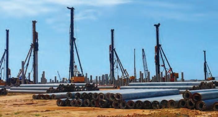
1.1 Background
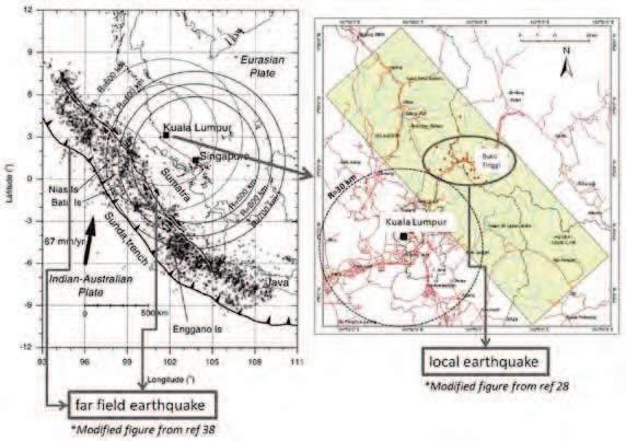
Geographically, Malaysia is located outside the on the stable Sunda plate (a part of the Eurasian plate)andisconventionallyperceivedasanearthquakefree zone. However, in recent years, Malaysia has experienced frequent reports of earthquake tremors generated mainly from the Sumatra fault zone (as shown in Figure 1). The generally increasing rate of earthquake activity in South East Asia in the aftermath of the Sumatra 2004 earthquake has been observed [5], as compiled in the database available from the National Earthquake Information Center (NEIC) of the United States Geological Survey (USGS).
Whilst no structural damage was reported, thousands of people in Malaysia were shaken by the earthquake tremor prompting the inevitable inquiring over the issue of structural safety of buildings in Malaysia [40, 41].To address this potential threat, the Institution of Engineers, Malaysia (IEM), has formed a Technical Committee on Earthquake
and published a position paper in 2007 [12], followed by the publication of a series of articles over the potential implementation of the Eurocodes for structural design [14].
is a need for seismic design in the nation and whether Eurocode 8 (hereafter abbreviated as EC8) is suitable for
Whilst most of the publicity has been on the Sumatra mega-thrust earthquake, a series of small earthquakes (M 0.3 to 4.2) were recorded by the local seismological network [28] within the Peninsula itself in the Bukit Tinggi area, Pahang, in November 2007. In other words, the threat of potential intraplate earthquakes generated by local inactive faults (including the Bukit Tinggi fault zone, refer to Figure 1) has been underrated. Given this combination of potential threats, it is appropriate to categorise Malaysia as a low-tomoderate seismicity region, similar toAustralia, Central and Eastern North America, Northern Europe and South China.
The situation has been evaluated seriously by the IEM Technical Committee. A series of technical meetings and symposia were conducted with the participation of invited international experts. Key events include a oneday workshop in June 2010, a two-day symposium and workshop in December 2011 [13] and the upcoming two-day symposium and workshop in April 2013. This paper aims to summarise the research work that has been undertaken in the past 18 months which shall form the basis of the recommended earthquake loading model for Peninsular Malaysia.
1.2 Seismic Hazard Assessment (SHA)
Since 1979, the Malaysian Meteorological Department (MMD) has installed 19 seismological stations in the Peninsula [25]. In addition, hundreds of years of historical
Sumatra fault zone has become available from the USGS/ NEICdatabase[42].Thishasenabledtheimplementationof the conventional Probabilistic Seismic Hazard Assessment (PSHA) methodology in determining the recurrence rates of various ground motion intensity levels at different locations around the nation. PSHA can be viewed as a statistical method for incorporating the information of seismotectonic features and all historic events in the prediction of a certain
The most commonly adopted algorithm was initially developed by Cornell (1968) [6] and further coded by McGuire (1976) [26] into a computer programme.
On the contrary, only a limited amount of local earthquake data was recorded from within the Peninsula itself. It is noted that the probabilistic approach would not be reliable in modelling the recurrence rates of local seismic events for the future if local (intraplate) earthquakes are being under-represented in the existing database. This lack of data syndrome is a common issue in many low-tomoderate seismicity regions. In this context, it is considered appropriate to adopt Deterministic Seismic Hazard Assessment (DSHA) as a supplementary or alternative approach of modelling [17].
DSHA was the standard approach of seismic hazard modelling during the said period (until the 1980’s) when the amount of recorded data was scarce. With an increasing amount of recorded data around the world, the use of PSHA has become more popular. However, recent destructive earthquakes raised concerns over the full reliance of results from PSHA for determining the required level of protection with the built infrastructure. There has seismology and engineering. Notwithstanding this, PSHA is well recognised in terms of its role in risk management and is undoubtedly an essential tool for assisting policy making by governments and the insurance industry.
From an engineering perspective, the safety of the built infrastructure in countering potential earthquake hazards is the most important consideration in determining the required level of seismic design loadings. It is reasonable
to be conservative and take into account uncertainties and unknowns through international benchmarking of seismic design practices, and with particular references to countries in a similar situation. The approach for determining the earthquake loading model should also be tailor-made to address local constraints as well as consider
It is therefore prudent not to simply adopt a commonly used code of practice for Malaysia.
Ground Motion Prediction Equation (GMPE) (commonly known as attenuation model) is the key component in SHA. GMPE predicts the intensity of ground shaking, based mainly on a given earthquake scenario which is expressed in terms of a Magnitude (M) and Distance (R) combination. Ideally, such a model should be developed based on locally recorded data. References to other generic models can also be made should they be deemed suitable. For far
models, namely that of CAM [31, 4] models by Megawati and co-workers [19], and a (generic) model developed by Atkinson & Boore (2006) [15, 16]. On the other hand, eight GMPEs as summarised in Ref.[22] have been adopted to assess the attenuation characteristics of ground motions in local earthquake events in Peninsular Malaysia.
1.3 National Annex (NA) to EC8
The long existence of British Standards in Malaysia will be replaced by the Eurocode, with the provision of the National Annex (NA) to take into account local conditions. EC8 (BS EN 1998-1:2004) [8] is the document recommended for the design of buildings against seismic actions. A design Acceleration Response Spectrum (RSA) which is scaled in accordance with the notional Peak Ground Acceleration (PGA) value is stipulated. Importantly, EC8 (Part 1
spectral shapes. An appropriate design spectrum model for Malaysia has become a crucial matter that is ought to be considered.
(background) seismicity that is affecting Malaysia, a hybrid approach of modelling (incorporating results from both probabilistic and deterministic assessments) was discussed and proposed in the workshop that was conducted in December 2011. Due consideration was given to international practices when the proposal was made. The recommendation of this hybrid approach was formally endorsed by all the participants of the workshop where representations from various stakeholders, the local professions and the academia have also been included.
Upon the endorsement, the IEM Earthquake Technical Committee has set up a working group (WG1) to elaborate on the recommended hybrid approach. This article provides a summary of the relevant research work that has been undertaken for the determination of the earthquake loading model for rock sites in Malaysia based on the endorsed approach. This involves the probabilistic assessment of
distant seismic hazard as well as the determination of local earthquake scenarios for engineering design purposes. A purposes.
soil sediments (as represented by the S-factor in EC8) is another important element of considerations in the NA to EC8. The incorporation of the site natural period as (along with the use of the conventional SPT and shear wave velocity values) has been considered as a more appropriate approach for regions of low and moderate seismicity. This recommendation has also been endorsed by all the participants of the December 2011 workshop. A by the authors and will be presented and discussed in the upcoming workshop (which is not included in this article as it only considers the ground motions on bedrock).
2.1
Far Field Earthquake Sources
Earthquake hazards from Sumatra have been generated from two major sources (Figure 1): (1) SundaArc subduction fault source off-shore of Sumatra; and (2) Sumatran strikeslip fault source.
(1) Sunda Arc subduction fault source off-shore of Sumatra
The subduction fault source is formed by convergence between the Indian-Australian plate and the Eurasian plate. Megathrust earthquakes including that ofAceh 2004 (M9.3) and Nias 2005 (M8.7) events were generated from this fault source. The distance from this fault source to Peninsular Malaysia is approximately 530 km – 730 km.
(2) Sumatran strike-slip fault source
The distance from the 1,500 km long Sumatran strike-slip fault source to Peninsular Malaysia is some 300 to 400 km and is much closer than the distance from the subduction fault source. The magnitude of recorded historical earthquakes generated from this fault source within the Sumatran island is limited to about M7.8.
2.2
Previous Studies
Numerous research groups have contributed to the affecting Peninsular Malaysia. This section provides a brief
1. Lam, Chandler, Tsang, Balendra and co-workers from the University of Melbourne, the University of Hong Kong and the National University of Singapore
2. Megawati, Pan, Koketsu and co-workers from the Nanyang Technological University Singapore and the University of Tokyo
3. Pappin and co-workers from Arup Hong Kong
4. Adnan, Irsyam and co-workers from the University of Technology Malaysia and Institute of Technology Bandung
5. Petersen and co-workers from the United States Geological Survey.
The literature review (presented in the 2011 workshop) provides coverage of some twenty research articles spanning the period 2002 – 2011 [1-3, 7, 9, 16-21, 23, 24, 27, 32, 35-39]. This database features a combination of PSHA and scenario-based DSHA studies. The research methodology and assumptions adopted in the DSHA studies have been clearly explained in Refs.[32, 19]. Numerous representative GMPEs for predicting ground motion levels as functions of magnitude and distance have been developed in these studies. Meanwhile, investigations adopting the PSHA as reported in eight research articles (e.g. [3, 16]), involved the use of a more extensive list of input parameters and modelling assumptions. The analysis output depends on the historical earthquake catalogue, completeness criteria, de-clustering method, source zoning and the use of the logic tree.
Most of the adopted GMPEs are empirically based and were derived from regression analysis of strong motion accelerogram data (e.g. Joyner and Boore, Campbell, Sadigh). Due to the paucity of recorded data for empirical regression analysis (which is common in low and moderate seismic regions including Malaysia), various researchers proposed GMPEs which were developed from studies involving the use of stochastic simulations of the seismological model (e.g. CAM, Atkinson and Boore), and method (e.g. Ref.[19]). In view of the inconsistencies of the predicted ground motion values from different GMPEs,
observations [4].
Two GMPEs reported in the literature have been validated based on benchmarking against ground motion data instrumentally recorded from a long distance. A brief introduction of the two GMPEs is presented below.
(1) Component Attenuation Model (CAM)
programme GENQKE for generating synthetic earthquake accelerograms based on stochastic simulations of the seismological model [29, 31]. Even though CAM was initially developed for the prediction of ground motions generated by local earthquakes, the modelling framework was found to be capable of predicting ground motions generated by
has successfully demonstrated its capability of modelling distant earthquakes affecting Singapore [32, 36, 37].
The mathematical framework of the seismological
A(f) = CM0S(f) GAA n(f) P(f)Va(f)
where CM0S(f) is the “source” component, GAA n(f) is the “path” component and P(f)Va(f) is the “local” component.
Adetailed review of the seismological model and stochastic simulation methodology can be found in [31].
Reliability
EverGUM by MENNEKES® . Receptacle combinations in
solid rubber enclosures.
„Flexible safety - portable distribution boards, receptacle strips and wall-mounted distribution boards.“
Elektrotechnik GmbH & Co. KG
MENNEKES
(2) Megawati attenuation relationship
Megawati and co-workers developed an attenuation relationship for modelling ground motions generated from the Sumatran fault source [20] and those from the Subduction fault source [21] in 2007 [39], and was revised in 2010 [19]. Synthetic seismograms which were derived
conditions and site-source distance ranging between 200 and 1,500 km. The use of the developed relationship for making predictions outside this distance range should be treated with caution.
where all parameters can be obtained from Table IV in Ref. [19].
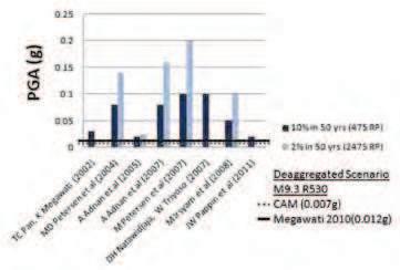
In addition to the deterministic studies as described above, Pappin and co-workers [15, 16] conducted PSHA for Malaysia based on historical earthquake data which has been recorded over the past 40 years since 1972, along with the use of the Megawati (2007) attenuation relationship [39] (i.e. not the most updated one). Based on the earthquake catalogue compiled from the USGS database, the seismic sourcezonewasdividedintofourcategoriesofseismogenic depth ranging between 50 and 500km, and an earthquake database in which small events (<M5) and aftershocks have been removed. Local seismic hazards were analysed using the attenuation relationship of Atkinson & Boore (2006) which was developed for the mostly cratonic crustal conditions of Eastern North America.
A summary of PGA values, corresponding to a return period (RP) of 475 years (10% probability of exceedance in 50 years) and 2475 years (2% probability of exceedance in 50 years), hereafter rounded off to 500 years and 2,500 years respectively, derived from various studies are presented in Figure 2 along with results from deterministic predictions based on the long distance scenario of M9.3 R530 and the use of CAM ( ) and Megawati (2010) (updated) ( ) attenuation relationship.
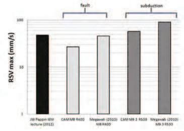
Whilst the PGA parameter is conventionally used for scaling a design response spectrum, the response spectral behaviour in the intermediate to long period range is actually represented by response spectral velocity parameter (RSVmax) which is a more robust and appropriate parameter for representing the effects of hazards on the built infrastructure.
The developed Uniform Hazard Spectra (UHS) have been de-aggregated into contributory earthquake scenarios [27, 3, 15]. For example, the earthquake scenarios of M8
to the mean hazard level for a RP of 2,500 years based on projected events generated from the Sumatran and subduction fault sources respectively. Values of RSVmax obtained from the de-aggregation analysis are presented in Figure 3 along with the predictions from CAM ( ) and from the Megawati (2010) attenuation relationship ( ).
2.3 Recommended Distant Earthquake Model
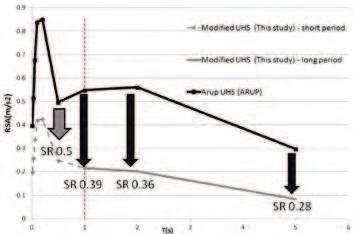
In addition to the deterministic studies that have been conducted to model the behaviour of distant earthquakes, comprehensive probabilistic studies have been undertaken more recently to model the aggregated earthquake hazards. The response spectrum produced by the aggregation analysis is known as the Uniform Hazard Spectrum (UHS) in which contributions from multiple fault sources have been taken into account [15, 16]. The attenuation behaviour of the simulated ground motions in the development of the UHS was based on GMPEs developed by Megawati (2007) for the large magnitude distant earthquake and by Atkinson & Boore (2006) for local earthquakes generated from a stable crustal structure. Different parts of the UHS
scenarios. For example, the short period range of the 2,500-year UHS in Figure 4 is controlled by ground motions generated by moderate magnitude earthquakes whereas the longer period range by the much larger magnitude earthquakes from longer distances.
There is a global trend to benchmark design seismic hazard level to a RP of 2,500 years as opposed to 500 years, in order to achieve a higher level of protection for civil engineering assets. In the low seismicity regions of the United Kingdom a RP of 2500 years has been stipulated in the NA of EC8 for collapse prevention limit state design. Similar design criterion has been adopted in Canada and China. In view of this trend, it is considered that the UHS of Malaysia should be based on a RP of 2,500 years. It is noted that the UHS model as presented in Figure 4
relationships. For example, the original attenuation relationship of Megawati (2007) [39] has been updated to Megawati (2010) [19]. In parallel with improvements made by the Megawati model, CAM has also been shown to be able to simulate ground motions that match the
the Aceh earthquake of 2004 and the Nias earthquake of 2005. To achieve a more robust UHS, the attenuation model has been revised in this study to incorporate both the updated model of Megawati (2010) [19] and the latest development of CAM [32]. A logic tree weighting factor of 0.5 has been allocated to both attenuation relationships in the aggregation analysis.
procedure comprising the following steps (refer to Figure 4):
a) Three earthquake scenarios, namely (1) M9.3 R530, (2)
calibration analyses to be represented by the original UHS. Earthquake ground motions simulated for these calibrated scenarios based on the use of the (original) attenuation model of Megawati (2007) [39] have been checked to ensure that their respective response spectra were consistent with the UHS at the four reference natural periods of 0.5s, 1s, 2s and 5s.
b) For each of the calibrated earthquake scenarios their respective response spectra were then recalculated using the updated attenuation model of Megawati (2010) [19] along with CAM based on equal weightings.
as the geometric mean of results associated with the three calibrated scenarios.
c) Scaling factors at the four reference periods were taken as the ratio of their respective revised and original response spectral values. The period dependent correctionfactoroftheUHSwasdeterminedaccordingly based on interpolation between the four reference periods.
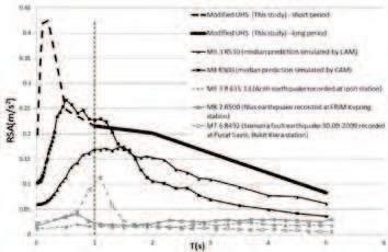
procedure as described is presented in Figure 5 along
events: (1) M9.3 R530 (median prediction simulated by CAM), (2) M8 R300 (median prediction simulated by CAM), (3) M9.3 R635.13 (Aceh earthquake recorded at Ipoh station), (4) M8.7 R500 (Nias earthquake recorded at
FRIM Kepong station) and (5) M7.6 R492 (Sumatra fault earthquake recorded at Pusat Sains, Bukit Kiara station).
3.1 Local Earthquake Activities
In 2007, the Bukit Tinggi area in Pahang had experienced a seriesofearthquaketremors.About24tremorsofmagnitude 0.3-4.2 were recorded by MMD over a period lasting for secondary school buildings and the police headquarter at Bukit Tinggi.
The occurrences of earthquake tremors outside Bukit Tinggihavealsobeendocumented.Tremorswithepicentres located within Peninsular Malaysia were widely felt in the mid 1980’s. These tremors have been interpreted as reservoir in Terengganu. 24 weak tremors were reported to have occurred in the period 27.7.1984 – 15.11.1985. Other isolated events have also been located in Jerantut Pahang, Manjung Perak and Kuala Pilah in 2009 [28].
3.2 Scenario-based Modelling and Recommended Local Earthquake Model
In view of uncertainties associated with local earthquake sources and the scarcity of recorded data, results from PSHA are considered to be unreliable for predicting future recurrence rates of earthquakes. In this context, SHA can be undertaken by the alternative scenario-based modelling methodology which is essentially deterministic in nature. This is referred herein as the DSHA approach.
Suitable M-R combinations will have to be predetermined if DSHA is to be used. The “newly discovered” Bukit Tinggi fault has been recorded to have generated
source from Kuala Lumpur and the Klang Valley is around 15km to 60km (Figure 1). Although the M-R combination of M4.2 R15 may well be considered to be the “critical earthquake scenario” in view of what has been recorded in recent times, it is inappropriate to do so simply because cannot be completely ruled out. It is therefore prudent to make reference to seismicity information on a global scale as opposed to restricting the scope of reference to the very limited database of records that has been collected from within the Peninsula to date.
From the global perspective, reference PGA values for RP of 2,500 years have been compiled from the literature for a number of major cities around the world. The level of
three major zones:
a) Low seismic zones: e.g. London (lower), Melbourne (mid), Hong Kong (upper) – <0.25g
b) Moderate seismic zones: e.g. Wenchuan (Sichuan), Christchurch (New Zealand) – 0.25g-0.50g
c) High seismic zones: e.g. Taiwan, Tokyo, Los Angeles –>0.50g.
A brief introduction of GMPEs has been given in Section 2.2. Eight GMPE models which have been developed independently in different regions around the globe, including two (NGA) model (Abraham and Silva (2008), and Campell and Bozorgnia (2008)) [34] which were originally intended for applications inWesternandEasternNorthAmerica,havebeenreviewed.
Their Response Spectral Displacement (RSD) values have also been collated for comparison in [22]. CAM [30, 31] that has been developed and used by the authors in numerous studies for different countries in the past has also been included as one of the considered GMPEs.
The database of earthquakes used in Lumantarna [22] features events of magnitudes in the range M5.5-M6.9, and much of the data were sourced from the PEER
Engineering Research (PEER) Center. RSD values predicted by the considered GMPEs are shown to be more consistent as the magnitude and distance values increase within the considered range: M5.5 R20 – M6.9 R40. The predicted mean Peak Displacement Demand (PDD) values (i.e. maximum value on displacement response spectrum) associated with an array of considered M-R combinations are listed in Table 1. The range of reference distances in the array is based on information shown in Figure 1. The four M-R combinations for the projected local earthquakes correspond with conditions of “low seismic zones” (PGA benchmarking. Thus, every individual M-R combination listed in Table 1 can be aligned with one of the following lower”, “mid” or “upper”.
response spectra estimated for a range of local earthquake scenarios. The original UHS model (primarily based on the considerations of distant events) has also incorporated local earthquake scenarios of up to M4.2 [15]. A PGA value of less than 0.04g is predicted for a RP of 2,500 years. Clearly, when it comes to international benchmarking the predicted level of seismic hazard by the presented UHS is somewhat too low for any area with a background seismicity. It is
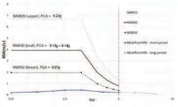
low seismic zone (in the case for London) is 0.1g which is aligned with the projected scenario of M6 R50.
Irrespective of what has been recorded historically in the area it is considered reasonable to adopt the “mid”
notional PGAvalues of around 0.13g on rock sites.This level design local hazards for the metropolitan area surrounding thecapitalcityofKualaLumpurandothermajorcities.These recommendations are based on international benchmarking and are irrespective of what has been recorded to date in the area over a very limited time span.
In Section 2 and 3, two design response spectrum models earthquake hazards respectively forming a hybrid model. Considerations for distant earthquake hazards are based Lumpur as reference (i.e. an epicentral distance of 600km is considered). Considerations for local earthquake hazards are based on international benchmarking as described. A design scenario of M6R30 (consistent with the “mid”
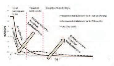
model the response spectrum in the natural period range of up to 1s. In summary, the long period range (> 2s) of the response spectrum is controlled by the considerations of
whereas the short period range (<1s) by the projected local earthquake scenarios.
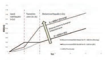
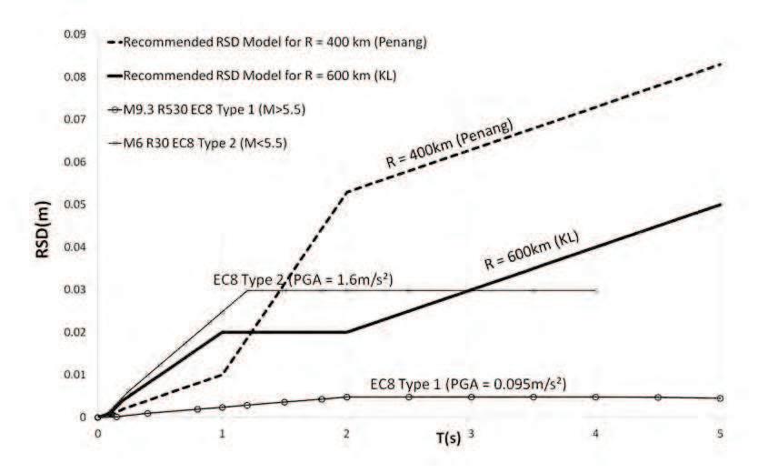
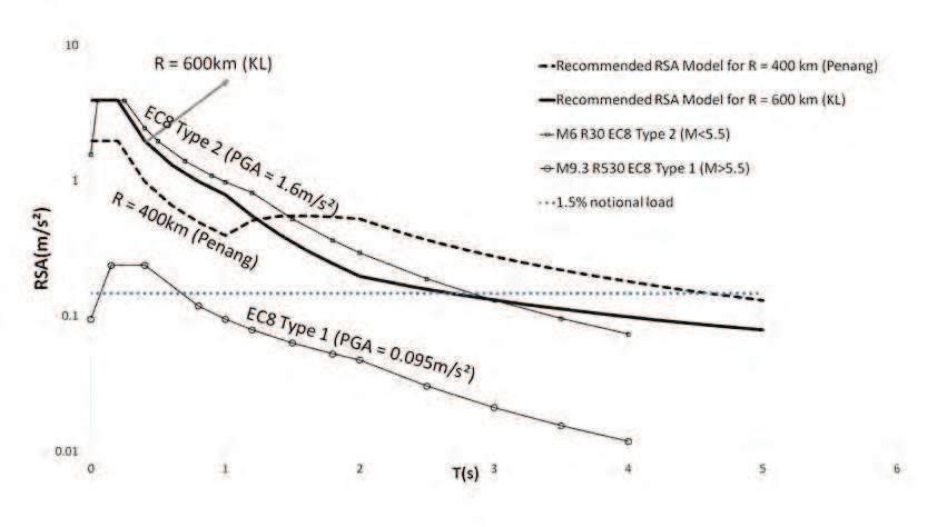
In unifying the two parts of the response spectrum (for distant and local earthquake hazards) there is a transition zone in the period range of 1s-2s. The RSD in the transition zone of this proposed hybrid model features a straight line bridging the two parts of the displacement response spectrum (Figure 7(a)). The same response spectrum is also presented in the conventional acceleration format in Figure 7(b).
4.1 Distance Effects
The general framework of the hybrid model as introduced herein can be extrapolated for use in different cities across Peninsular Malaysia by making use of the “path” component of the seismological model ( ), which is principally a function of distance R [31]. The nearest distance of a city to the Sunda Arc subduction fault source off-shore of Sumatra will control the value of PDD which characterises
Distance Factor (DF) = (600/R)2.4 ; R in unit km
SD(2) = 20 * DF > SD(TD) ; SD in unit mm , along with the parameters summarised in Table 3, whilst the compatible spectralordinatesoftheconventionalaccelerationresponse spectrum can be conveniently calculated using
R = 600 km from the Subduction zone off-shore of Sumatra. The response spectrum for another city such as Penang (R = 400 km) which is closer to the Subduction zone than Kuala Lumpur can be scaled accordingly by the use of the Distance Factor (DF) (refer and Table 2), which was derived in this study. The RSD value at T = 2s can be scaled using . The values of DF and the corresponding RSD value at T = 2s of some selected cities can be found in Table 2.
In effect, the format of the benchmark design response spectrum model for Kuala Lumpur is consistent with that stipulated in EC8 up to T = 2s. Considering the unique distant hazard in Peninsular Malaysia, location-dependent spectral ordinates would result beyond T = 2s.
4.2 A Comparison with Recorded Data
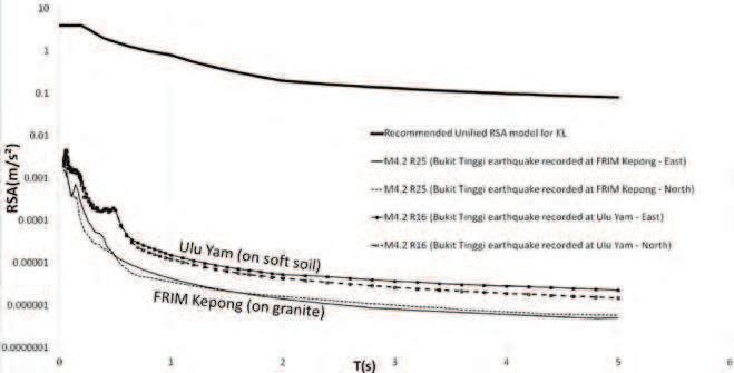
to envelope them. Despite the scarcity of recorded data for local earthquakes (e.g. Bukit Tinggi), the highest recorded
model of Kuala Lumpur. Data from two MMD stations (1) FRIM Kepong (R = 25 km) sitting on granite foundation and (2) Ulu Yam (R = 16 km) sitting on soft soil foundation
RSAmodel is conservative enough for civil protection with a 2,500 year RP.
4.3 A Comparison with EC8
The simulated response spectrum for the large magnitude distant earthquake scenario of M9.3 R530 (which is 2) is used to scale the model response spectrum of EC8 Type 1 (for M>5.5) based on the same PGA value as shown in Figure 9(a). Similarly, the simulated response spectrum for the with notional PGA value of 1.6 m/s2) is used to scale the model response spectrum of EC8 Type 2 (for M<5.5) as
q factor of 1.5 as stipulated by EC8 have been adopted in the comparison. It is shown that the shapes of both Type 1 and 2 model spectra are comparable to the respective
that the spectral values could have been understated by both EC models in the longer period range depending on the location of the city. The same response spectra are also presented in the conventional acceleration format in Figure 9(b).
4.4 The 1.5% Notional Load
As shown in Figure 9(b), the notion of adopting a nominal format of providing coverage for the seismic design
view of the non-conservatism of this simple provision, the importance of incorporating proper seismic design requirement for Peninsular Malaysia is now evident.
The peninsula of Malaysia is subject to a combination of earthquake threats that can be generated from a multitude of seismic sources. The Sunda Arc subduction source off-shore of the Sumatra Island has been attracting most of the publicity following the aftermath of the phenomenal M9.3 Aceh earthquake event of 2004. Although the level of ground shaking experienced that event, a much higher level of hazard is predicted for a much closer epicentral distance which is deemed possible. Another notable distant fault source is from the
Sumatran island itself. Although this second fault source is much closer to the Peninsula, its estimated response spectral level in the high period range is not as critical because of its relatively modest upper magnitude limit. Both elements of distant earthquake hazards have been subject to detailed research investigations based on large quantities of seismological data recorded to date from the
the literature to date have been associated with these two distant earthquake generating mechanisms. The third potential earthquake source is what is known as background seismicity which refers to local earthquakes generated from within the Peninsula.
Local earthquakes that have been documented to date were only generated from the Bukit Tinggi fault which is located some 15 to 60 km away from the metropolitan area surrounding the capital city of Kuala Lumpur. None of these local earthquake events were of engineering given that earthquakes of magnitude 6 are well within the credible limit in regions of low-moderate seismicity (intraplate) areas, the potential hazard that can be generated from local earthquakes can be much higher than what can be inferred from the very limited current historical archives.
The very complex combination of seismic activities affecting the Peninsula means that the generic EC8 (Type 1 and 2) response spectrum models should not be adopted automatically. Thus, the response spectrum principles.
Numerous response spectrum models have been developed from probabilistic, or deterministic, seismic hazard analysis for the region, but most of the data used in these analyses were associated with the two distant fault sources. Because of the infrequent and random nature of local earthquakes, their potential hazard has been underrepresented in (the usual) probabilistic evaluation analysis conducted to date. Applying probabilistic analysis in an area which are so lacking in local seismicity data will only produce hazard maps featuring “bull eyes” which are clearly counter intuitive. The disastrous consequence of paying blind faith to results from probabilistic analysis was well demonstrated in the destructive earthquake events in
the recent past including the Christchurch Earthquake in the South Island of New Zealand in February 2011. Hence, a hybrid modelling approach has been adopted to address this shortcoming. In the hybrid model, the part of the response spectrum in the long period range (>2s) is based on the considerations of distant earthquakes. A mega large magnitude (M9.3) earthquake from some 400 to 600km distance has been considered for design purposes. The original UHS model of ARUP
the latest attenuation models for such distant earthquake scenarios. A logic tree approach was employed to take into account contributions from different research groups. The part of the response spectrum in the shorter period range (<1s) was derived from international benchmarking in which seismicity patterns around the world are resolved into the “High”, “Moderate” and “Low” seismic zones The Peninsula on the whole has been ranked as a “low”
within the “low seismic zone” category. The seismicity of the capital city of Kuala Lumpur and the surrounding metropolitan area has been assigned to the sub-category of “mid”. The earthquake scenario of M6 R30 that is
earthquake scenario can be predicted based on GMPE’s that have been developed around the globe for local earthquakes. A high level of consistencies amongst the models in their predictions of long period spectral properties offers robustness to the predictions and adds
ranges is also featured in the hybrid model to complete the construction.
The authors would like to thank the IEM Earthquake
given to conduct the research. The recorded earthquake data information provided by MMD is acknowledged. The authors are grateful for the continuing assistance given by the post-graduate earthquake engineering research group in Melbourne University.
the upcoming events.
Geotechnical Engineering Technical Division
Water Resources Technical Division
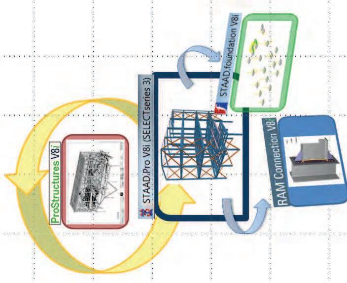
Advanced features
2
Besides conventional analysis, STAADProoffers geometric NL, pushover, buckling and time history analysis with state-of-the art analysis engine.
Interoperability General structural analysis, design of members, connections and foundations, with intelligent steel drafting –all in ONE model through ISM
1
Renowned brand name
3
STAAD serves practicing engineers for almost 30 years, giving reliable results in all types of stru ctural application projects. RAM Connection is widely used in the states and now is available in Asia. Prostee lhas built its name in Australia, widely used for steel project intelligent drafting.
International design codes STAAD has more than 70 international codes. Steel beams, columns, bracing, connection and foundation design can be easily adopted in Malaysia engineering practice since BS8110, BS5950, EC2, EC3 are available for with Malaysia Annex.
4
Navigator Why need messy paper based checking and reviewing? Navigator gives you the digital flexibility to find steel members information in model, CLASH detection and
5
THE INAUGURAL MEETING OF IEM
AS planned, the Inaugural Meeting of IEM was held on 1 August 1958 at 9.00 p.m. at No. 23 Perak Road, Kuala Lumpur, the residence of Mr. Lau Foo San. The meeting was attended by 39 engineers from various government agencies and the private sectors (refer to list of names attached). The participating engineers had elected Encik Yusof bin Hj. Ibrahim as the Chairman and Mr. Lau Foo San as the Hon. Secretary to subsequently, the drafts of the Constitution and By-Laws were deliberated, voted, and accepted in principle.
During the deliberation, an important issue was raised by Mr. Ng Ek Poh (Telecoms) and Mr. M. Tharmalingam (Mech. P.W.D). They feared that represented”. However, Encik Yusof had reassured them that the Committees would see to it that an even representation would be obtained in the future.
(Note: The above concern of the two engineers and the assurance given by the Chairman were again addressed to the late Tan Sri Ir. J.G. Daniel during an interview on 20 March 2011. He recalled that these had resulted in an unwritten rule or understanding. He said that . Thus, the unwritten rule of not having the President and Deputy President from the same engineering discipline has been a practice of the IEM for many years).
Apart from the above, it was proposed by Mr. Chew Kam Pok that . The motion was seconded by Mr. A. Navaratnam and it was put to a vote. The motion was carried out.
IEM Council Members. The elected Council Members were as follows:
President: EncikYusofbinHj.IbrahimP.W.D
Vice President : RajaZainalb.RajaSulaimanC.E.B
Hon. Secretary : Mr.LauFooSanPrivatePractice
Hon. Treasurer : Mr.ChewKitLinP.W.D
General Members : Mr.ChewKamPok
Mr.A.B.Bhatt
Mr.PhilipChow
Mr.Aw-YongHongChiew
Mr.ChanPengKhoon or Mr.DalipSingh
The Inaugural Meeting was adjourned at 10.30 p.m. with a note of thanks to the then President and the Secretary for their unfailing support towards the success of the Institution.
With the formation of IEM, the Joint Overseas Group of U.K. professional bodies was advised to dissolve itself. The Group later donated its entire funds to the IEM and decided not to hold any further activities in the country.
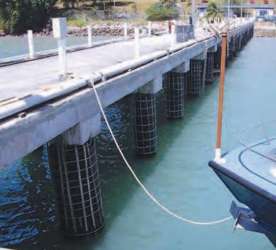
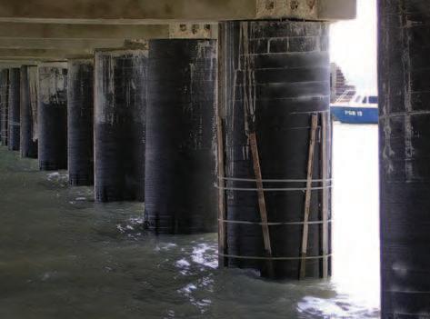
In some early and a few more recent segmental bridges erected through span-by-span erection in Malaysia, especially those associated with metro rail bridges, dry joints between precast segments were primarily utilised to reduce cost and construction time as well as to eliminate potential problems with epoxy applications.
The structures were generally designed with only external post-tensioned tendons protected by High Density Polyethylene ducts. No reinforcing or prestressing steel extended across the joints.
The code of practice to be used in Malaysia for concrete bridge design is BS5400 Part 4. This code does not cover the use of external tendons or dry joints. Reference to the Highways Agency Design Manual for Roads and Bridges (DMRB) documents BD58 and BA58 can be used to supplement BS 5400 Part 4 and to provide design guidance and requirements on the use of external unbonded
of dry joints is given.
It is generally accepted that dry joints give a lower ultimate moment and ultimate shear capacity than glued match-cast joints with precast segmental construction. It is therefore necessary to take this into account by introducing adjustments to the design approach and requirements. This design note compares the commonly available methods used in the design of precast segmental decks and recommends the design approach to be employed where dry joints and external tendons are used.
Design references used in the comparison include: BS5400: Part 4 – 1990 Code of Practice for the Design of Concrete Bridges, BD58/94 The Design of Concrete Highway Bridges and Structures with External and Unbonded Prestressing, BS EN 1992-2: Eurocode 2 Design of Concrete Structures,
of Segmental Concrete Bridges 2nd Edition 1999, by
Nigel Hewson,
Dry Joint Behaviour of Hollow Box Girder Segmental Concrete’ New Delhi, 26-29.11.2004.
Decks with dry joints behave differently in bending with ultimate loads to those using glued joints. The epoxy glue used between the segments creates a bond of greater strength than the concrete between the segments. No such bond is present with dry joints meaning that when ultimate limit state loading is applied the joints decompress and open up. This will lead to a reduction in structural
rotations concentrated at joints. The ultimate limit state failure mechanism with dry joints and external tendons is due to concrete crushing on the compression side due to excessive strains.
As shown on Table 1, of all the design codes investigated, the only design code to recognise the different ultimate bending failure mechanism of dry jointed decks as
for Design of Segmental Bridges.Alower strength reduction factor, , is applied to the ultimate bending resistance for dry joints as compared to glued joints. For glued joints = 0.90 and dry joints now superseded andAASHTO has prohibited the use of dry joints since 2003.
Design Code/ReferenceNotes
BS5400: Part 4 – 1990
(Note: Not applicable to dry jointed decks) for the design of decks using external tendons with dry joints.
BD58/94: The Design of Concrete Highway Bridges and Structures with External and Unbonded Prestressing the design of decks with dry joints.
BS EN 1992-1-1:2004 the design of decks with dry joints.
AASHTO Guide
Construction of Segmental Concrete Bridges 2nd Edition 1999
Lower strength reduction factor, , used for dry joints as compared to glued joints. = 0.90 Glued Joints = 0.85 Dry Joints
It has been successfully shown that there is a good correlation in behaviour of dry jointed segmental bridge
Global British Education since 1821
data. This is described in the paper, “Precast segmental box girder bridges with external prestressing – design and construction by Prof. Dr Ing. G. Rombach”.
Withahistorydatingbackto1821,wehaveestablished a reputation for world-class teaching and practical, leading-edge research, which has made us one of the top UK universities for business and industry.
Heriot-Watt University Malaysia offers you the opportunity to study programmes that help you establish a successful career in areas such as Engineering, Actuarial Science, the Built Environment, Oil and Gas and Business and Management.
Over 94% of Heriot-Watt graduates are in employment or further study within 6 months of graduation.
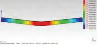
be created to determine the ultimate limit state response can be plotted against increasing applied live load bending moment. The bending moment being increased incrementally until the model shows the deck has failed due to concrete crushing in the extreme compression
verify the ultimate limit state capacity. The Figure 1 from joint behaviour at the ultimate limit state, with the joints opening up over mid-span. This analytical approach can be used to determine the ULS moment capacity of the span and the increase in stress in the tendons at failure.
The design rules for shear of sections between joints described in BS5400: Part 4 are based on test results for bonded tendons. Consequently their use for external unbonded tendons is inappropriate. Designing prestressed concrete bridges with external tendons in the UK requires the BD58/94 standards to be used.
The DMRB document BD58/94 does give a method for designing sections with external unbonded tendons. This is to treat the section as a reinforced concrete column section with an externally applied load. However, in general this approach is generally considered conservative and it also does not make any allowance for the opening that may occur at dry joints. The opening at the joint reduces the depth through which the web shear compression strut can pass.
Segmental Bridges also uses a strut and tie model to determine shear capacity. However, it makes no reference to the design of decks with dry joints or limitations on the size of the compression strut due to the opening of the joints. The strength reduction factors, , for both glued and dry joints is = 0.85.
It is proposed that BS EN 1992-2 to be used for
Joint opening joints
reference is made to the design of segmental structures with precast elements and unbonded prestressing. The code makes allowance for the decompression of joints under ultimate limit state loading and the subsequent reduction in depth through which the compression strut can pass.
Typically, the shear design of dry joints relies on the friction
capacity of the concrete interfaces between shear keys and the shear resistance of the shear key. A comparison between the various codes of practice and methods available for the design of joints in segmental bridges has
design of dry joints. Details of the comparison are provided in Table 2 and an example of typical shear capacities are given in the attached calculations shown in Table 3.
Design Code/ReferenceEquationNotes
BS5400: Part 4 – 1990
(Note: Not applicable to dry jointed decks)
BD58/94 The Design of Concrete Highway Bridges and Structures with External and Unbonded Prestressing
Ak = 744 in2 = 5800 psi f pc = 870 psi A sm = 93 in2
Note: The use of Type B (Dry) Joints was prohibited by AASHTO 2003 Vuj = 5226 kN
BS5400 Part 4 1990 – Code of Practice for Design of Concrete Bridges (Clause 6.3.4.6)
ULS Shear Capacity V = 0.7 x (tan 2) × × Ph
where 2 = 0.942 Rads = 0.87
Ph =15000 kN NOT APPLICABLE TO DRY JOINTS V = 12561 kN
Symposium Segmental Construction in Concrete, New Delhi 26-29/11/2004
Shear Strength V
where j = 0.5
Ajoint = 539750 mm2
fck = 40 N/mm2
n = 6 N/mm2
Ak = 480000 mm2 = 0.65 Vuj = 2397 kN
BS EN 1992-2 – Eurocode 2 Design of Concrete Structures
Design Shear Stress Edi = × VEd / (z x bi )
Design Shear Resistance Rdi
where VEd = 1200 kN
z = 1250 mm = 1.0
bi = 425 mm
c = 0.35
n = 6 N/mm2
fctd = 1.67 N/mm2 = 0.6
Edi = 2.26 N/mm2
Rdi = 4.18 N/mm2 V = 2223 kN
The code of practice to be used in the design, BS 5400: Part 4, does not contain any guidance on the use of dry joints. The clause relating to the shear design of joints in segmental bridges is not applicable for the use of dry joints. The Highways Agency DMRB document BD 58/94 can be used to supplement the code. This document permits the use of dry joints with external unbonded prestressing. However, it does not give any direction on the design of the joints.
Since the shear design of dry joints is not covered in BS 5400: Part 4, alternative design methods have been examined. The use of dry joints is covered by BS EN 1992-2 and guidance is given to enable joint shear capacity to be determined. Reference has also been made to the AASHTO design standards. The use of dry joints has been prohibited in precast segmental bridges by AASHTO since 2003. However, before this date,
Segmental Bridges, 1999, has been used to determine the capacity of a typical dry joint. Finally, reference has been made to the paper, Dry Joint
Segmental Construction in Concrete, New Delhi, 26-29.11.2004.
As shown in the example in Table 3, calculations for a typical box section
AASHTO gives the greatest capacity followed by BS EN 1992-2. The BS EN 1992-2 capacity compares well with the values determined using the paper
Construction by Nigel Hewson.
It is also common to allow for shear keys to be damaged during construction. It is therefore proposed to base the joint design on the area of shear keys reduced by minimum 5%.
Since the current BS 5400: Part 4 does not cover the design of precast segmental box girder with dry joints and external tendons, it is inappropriate for the designer to treat the dry joint design as a wet or epoxy joint design by using the formulae in BS 5400: Part 4, which will give a higher shear and moment capacity as compared to the actual resistance capacity.
5, Jalan Pemberita U1/49, Temasya Industrial Park, Glenmarie, 40150 Shah Alam, Selangor, Malaysia. Tel: +603-5569 3698 Fax: +603-5569 4099 Email: alphamail@alphakl.com
WE
LIFTS ARE DESIGNED TO BE “FAIL-SAFE”: HIGHLIGHTING THE BASIC SAFETY FEATURES OF LIFTS
It is shocking to note that yet another public facility had failed to function and killed a woman passenger. We should be thankful the lift was not fully occupied. The loss of a single life is horrible enough. The question that begs to be asked is why did this incident happen? Could we have taken necessary precaution to ensure such incidents do not occur?
The answer is a resounding ‘yes’ and it hinges on a good and committed maintenance programme. For centuries, lifts have proven to be effective vertical transportation systems and as engineers we can attest to this. We are aware that poor maintenance and even negligence can result in mishaps but we do have preventive measures that can save lives.
cable snaps the remainder four would ensure safe travel in the wire rope must be properly installed, aligned and calibrated by an experienced technician to function effectively. Even with the snapped hoisting ropes the free falling lift car would be stopped by the mechanical brakes on the main guide rails as the last line of defence before it slammed on the buffer in the work.
The mechanical and material specialists will be able to give their professional and analytical views on this impulsive force which was so powerful that all strands of wire rope
speculate that poor maintenance or even no maintenance could be the cause for this incident. The persons assigned to
explanation on the level of maintenance that has been carried out.
Moreimportantly,whetherornotthequalityofmaintenance service provided was below par is the main concern. Were skilled technicians assigned to carry out maintenance works? Were genuine spare parts being used? If the answers are NO, it is only right that the appropriate action in accordance with the relevant regulations be taken against the maintenance supplier.
We also believe that the Department of Occupational Safety and Health (DOSH) should do their part to ensure that only authorised lift vendors are registered as maintenance companies, and only such maintenance companies are allowed to perform maintenance works. We further urge the regulatory agency to oversee all such maintenance companies to ensure
carry out all maintenance work and to certify the work done at the site.
We understand that there is a shortage of competent
maintenance work. Hence, we strongly recommend DOSH to certify more of such persons under the National Occupational Skill Standard (NOSS).
The IEM hopes that proper investigations will be carried out to determine the cause of the mishap. If there is a need, the IEM will be pleased to offer its services. ■
(Sourced from the New Straits Times, 2 March 2013)
(Sourced from The Star, 11 March 2013)
(Sourced from The Sun Daily, 12 March 2013)
(Sourced from The Sun Daily, 7 March 2013)
(Sourced from The Star, 10 March 2013)
LED Lighting Innovation
Promo ng Safer Skies
With the boom of telecommunica ons and the avia on industry, avia on safety should be regarded as one of our foremost priority. DCA Malaysia and ICAO safety standards and regula ons help promote safe skies for all. The challenge is to mark all tall buildings, telecommunica on towers & structures with the appropriate and approved avia on obstruc on light for avia on safety purpose. Buildings, towers, or structures above 45m require the use of Medium Intensity Lights for night marking
AVIALTE is a specialist manufacturer of LED avia on obstruc onbeacons(OB),warninglights,usedforobstacle marking of telecommunica on towers, high buildings, transmission lines for avia on safety purposes.
With our strong founda on and R&D in avia on ligh ng, we con nuously develop avia on lights that ts ICAO requirements and also AVIALITE's core principle: One that is
AVIALITE patented OB lights are herme cally sealed and fully integrated. Inherently built in with ligh ng surge protec on and IP67 (Ingress Protec on) cer ed, our lights are durable, robust and reliable. It is compact and lightweight, providing easier handling and installa on on site. Backed by vast experience and strong R&D capabili es, we are able to design and customize products for our clients.
A short course entitled, “Life Threatening Incidents of Explosions, Fire and Impact in Building Structural Design to Mitigate Disaster” was organised by the Civil & Structural Engineering Technical Division of The Institution of Engineers, Malaysia (IEM) on the 29 and 30 May 2012 at Hotel Armada, Petaling Jaya, Selangor. A total of 89 participants had attended the course
A total of eight technical sessions were conducted by three experts from Monash University and University of Melbourne, Australia:
i. Lessons Learnt from Past Events
ii. Structural Design for Fire Resistance (I)
iii. Structural Design for Fire Resistance (II)
iv. Structural Design for Impact Actions (I)
v. Structural Design for Impact Actions (II)
vi. Blast Actions (I)
vii. Blast Actions (II)
viii.Structural Design for Impact Actions (III).
The subject of Fire Design according to the Eurocodes was delivered by Prof. Bill Wong from the University of Melbourne, Australia. He provided illustrations of
structural failure of buildings and bridges, as well as their consequences. According to Eurocodes, Fire Design is meant to minimise the loss
Approach, a methodology of design that is totally new in structural design philosophy. For example, the column is designed for the ultimate limit state in selection of materials, size and reinforcement to support the ultimate load. In cases where the column will require say about 80% of the capacity for service load, the remaining will be utilised for
Based Approach.
Prof. Bill Wong also illustrated the methods used in Eurocodes for design of structural concrete and steel
a steel section was distributed to the participants without any charge. It was amazing to hear that the Windsor Tower
18 hours. He also illustrated the unfortunate case of the 11 attack’ (911) by terrorists, where an aircraft hit the said building.
The subject of explosion was delivered by Dr Tuan Ngo, a senior from the University of Melbourne, Australia. He introduced the subject by illustrating the effects of explosion created by terrorists all over the world. For example: Ronan Point (1968); St Mary Axe, London (10 April 1992); Bishopgate, London (24 April 1993); Oklohoma City (19
Jakarta (2004).
He also illustrated how blasting propagates and its effects on buildings, especially the façade. Dr Tuan Ngo also provided some methods of design that would help resist blast forces. However, human beings would have no chance of surviving a blast because of the extreme pressures.
The subject of Impact loading was delivered by Prof. Nelson Lam from the University of Melbourne, Australia. He is no stranger to IEM members as he has conducted many short courses pertaining to Earthquake Engineering. He illustrated the effect of impact load on a structure for both horizontal and vertical structural members. Various and cantilever. Impact of objects on slabs was also demonstrated.
The most important aspect of his presentation was his intention to unify the method of design to that of other method used in earthquake resistance design for buildings where the response spectrum is used. This will be a great be required for impact loading. The existing seismic code
FORUM
IEM hosted a courtesy visit by a delegation from the Institution of Chemical Engineers, UK (IChemE) on 3 October 2012 at Wisma IEM. IEM was represented by Deputy President, Ir. Choo Kok Beng, Executive Director, Ir. Cheang Kok-Meng, as well as representatives from the Chemical Engineering Technical Division (CETD), namely the CETD Chairman, Ir. Prof. Dr Dominic Foo Chwan Yee (then Deputy Chairman) and CETD Secretary/Treasurer, Ir. Thayananthan Balakrishnan (then Committee Member). The IChemE was represented by its Deputy CEO, Mr. Justin Blades; Chairman of IChemE Malaysia Branch, Ir. Prof. Dr Abdul Wahab Mohammad, and the Southeast Asia Regional Manager, Mr. Mohan Balasingam. The purpose of the visit was to identify the areas of interest for potential collaboration between these two organisations in the near future
To kick start the discussion, Ir. Cheang Kok-Meng had he gave a more thorough overview about IEM, such as its
current membership which had reached 23,000 throughout Malaysia, with its 18 Technical Divisions and three Special Interest Groups, covering the four major (i.e. civil, mechanical, electrical and chemical) and minor engineering disciplines.
According to Mr. Justin Blades, IChemE is an international body representing chemical engineers worldwide with a total membership of 35,000 across 120 countries. He also explained that the branch in Malaysia had recorded the strongest membership growth in the past few years.
The two organisations have reached an agreement that it was timely
the corporate membership of both parties, which needed to be explored in detail with the formation of a special committee. Ir. Prof. Dr Dominic Foo also suggested that various activities could be jointly organised between CETD and the IChemE. The visit concluded with a proposal to sign a Memorandum of Agreement between IEM and IChemE in the near future.
THE IEM-KoreanConcreteInstitute(KCI)DialogueMeeting hosted by the Civil & Structural Engineering Technical Division of The Institution of Engineers, Malaysia (IEM) was held on 20 July 2012 at Wisma IEM, Petaling Jaya
The IEM delegation which consisted of six members was headed by the Vice President, Dato’ Ir. Lim Chow Hock, together with four secretariat staff. The Korean Concrete Institute (KCI) team was represented by nine delegates led by Prof. Jongsun Sim, the President of KCI. Out of the nine members whom were present, four of them were from KCI itself and the rest were chosen from the concrete-related industries in Korea.
Soon after the arrival of the KCI delegates at 1.30 p.m., the event started by Dato’ Ir. Lim Chow Hock welcoming the KCI delegates to IEM. This was followed by a mutual introduction amongst members from the two institutions
beginning from by Dato’ Ir. Lim, followed by the IEM delegates and secretariat staff, and subsequently, the KCI members led by Prof. Jongsun Sim and the rest of his delegation.
Dato’ Ir. Lim went on to thank the KCI delegation for initiating this dialogue meeting. He mentioned that as an institution in Malaysia that represents and is constantly looking after the interest of engineers in this country, IEM welcomed this commendable move by KCI and believed that it would foster a closer working relationship between the two institutions.
After delivering his short speech, Dato’ Ir. Lim then handed the session over to the Executive Director of IEM, Ir. Cheang Kok Meng for a presentation on IEM. This presentation aimed to instill a clearer picture of IEM as a professional institution in Malaysia to the KCI members.
In return and upon the invitation of Dato’ Ir. Lim, the head of the KCI delegation, Prof. Jongsun Sim, too gave a presentation on KCI and its activities. He then informed the participants that KCI actually consists of professionals
he went on to explain about the structure, activities, membership and other details of his organisation.
On the subject of collaboration and joint activities, both IEM and KCI had signed a Memorandum of Understanding (MoU) on 14 November 2011. This MoU is for three years, with automatic renewal for another three years. Based on this document, the two institutions have agreed to
For example, KCI would conduct evening talks at IEM premises, engage in the mutual exchange of publications and journals with IEM and hold other similar activities.
Before the meeting ended, Dato’ Ir. Lim Chow Hock informedKCImemberofafeweventsofIEMwhichincluded
“Cradle to Cradle Structures in Transport Engineering” (10 September 2012), Engineering Week 2012, and the Engineering Invention and Innovation Expo (EINIX). The latter was to promote the engineering profession to the public via exhibition of creative inventions and innovative products of undergraduates from the local universities in Malaysia. KCI was warmly encouraged to participate in such activities and other future events of IEM.
The meeting ended with a note of thanks to the Chairperson. This was soon followed by a brief group photography session and an exchange of souvenirs before
the meeting was adjourned and later reconvened as the ‘Afternoon Forum’ at Wisma IEM, an event that was open to both IEM members and invited guests.
The ‘Afternoon Forum’ started off with a 15-minute presentation given by a committee member of the Civil and Structural Engineering Technical Division of IEM on “Concrete Engineering Practice and Seismic Design Standards Development in Malaysia”
Judging from the good response as well as the active interaction between the speakers and the participants, especially during the Q&Asession, it was fair to conclude that it had been a meaningful event with most, if not all, of its objectives being achieved.
The dialogue meeting concluded as members from both institutions adjourned for dinner at a nearby restaurant where a more casual and cordial atmosphere prevailed and helped to foster closer friendship among the delegates.
THE ‘Two-Day Course on Analysis and Design to EC8
i. Earthquake Basics and Introduction to Seismic Design
ii. Earthquake Loading Models Proposed for Peninsular Malaysia
iii. Concepts and Computational Principles of Dynamic Analysis
iv. Operating Dynamic Analysis of Buildings for
i. Design of Reinforced Concrete Buildings of
ii. Concepts and Principles of Deformation Modelling of Reinforced Concrete
iii. Concepts and Computational Principles of
IEM SNAPSHOTS
Advanced air nozzle technology
Replacing open pipe installations with Silvent compressed air nozzles normally means:
For more information, please contact:
Ck Wong 012-6695954
Gwen Lee 012-5758277
Kejuruteraan Semangat
Maju Sdn Bhd
9 Jalan USJ 10/1D, Taipan 47620
Subang Jaya, Selangor
AT the 9th International Symposium on Advancement on Cement and Concrete Industries held on 19 November 2012 in Seoul, South Korea, Ir. Prof. Dr Jeffrey Chiang Choong Luin, Hon. Secretary of IEM was invited to deliver a presentation entitled, “Current Practice in Cement and Concrete Industries in Malaysia: From the Perspective of IEM”. The event was organised by the Korea Concrete Institute (KCI)
Reproduced below is a photograph of the event together with an acknowledgement note from KCI.
AS an initiative under the Government Transformation Programme, the Corporate Integrity Pledge (CIP) is a document that allows a company to makeacommitmenttoupholdtheAnti-CorruptionPrinciplesforCorporations in Malaysia.
By signing the pledge, a company is making a unilateral declaration that it will not commit corrupt acts, will work toward creating a business environment that is free from corruption and will uphold the Anti-Corruption Principles for Corporations in Malaysia in the conduct of its business and in its interaction with its business partners and the Government.
The effect of entering into the pledge is two-fold. Firstly, a company can use this Pledge to set itself apart from its peers by demonstrating to its stakeholders that its business operations do not include any hidden risks or costs that are associated with corrupt activities. By signing the pledge, the company can be listed in the register of signatories that is posted on the website of the Malaysian Integrity Institute (IIM). Secondly, a company will be making a clear stand of how it operates, and this will serve as a guidance to the company in its business interactions, should it be faced with the possibility of condoning any payments or other activities that would amount to corruption.
This Pledge is not issued by any regulator or authority but is a result of collaboration between the Malaysian Anti-Corruption Commission (MACC), Bursa Malaysia Berhad, the Companies Commission of Malaysia (SSM), the Malaysian Institute of Integrity (IIM), Securities Commission Malaysia (SC), Transparency International Malaysia and the Performance Management
THE great Sahara Desert was on my list of places to visit before I leave this world, and when my wife and I together with a friend of ours were travelling in Algeria and Tunisia for 1½ months in November and December 2012, we had the good fortune of being able to spend half a month exploring a sizeable part of the great desert that makes up the bulk of Algeria’s territory.
The Sahara has an area of over 9.4 million km², about the size of USA. It covers much of Morocco, Western Sahara, Mauritania, Senegal, Mali, Algeria, Niger, Tunisia, Libya, Egypt, Chad and Sudan. The name given to this vast area, i.e. Sahara, comes from the colloquial Arabic word for desert.
Algeria is a North African country located on the southern shores of the Mediterranean Sea. With an area of 2,381,741 km², it is the largest country in Africa after the secession of South Sudan from Sudan and is more than 7 times the size of Malaysia. However, about 80% of its territory is part of the great Sahara Desert which is understandably very sparsely populated, and so this large country only has a population of 37 million people.
After spending about one week exploring the cities and Roman archaeological sites in the northern part of the country, we left Tlemcen for Taghit which is about 680 km to the south. We soon entered the great desert with vast plains of little vegetation on both sides of the road. Taghit itself is a pretty oasis town set in a broad valley with giant sand dunes to its south.
As we continued our journey to Timimoun and then to Ghardaia, we encountered more and more giant sand dunes and were thoroughly amazed and mesmerized by those spectacular sculptures of sand which are the result of the forces of nature.
Sand dunes are what most people will expect to see in a desert, but in the great Sahara Desert, sand seas constitute less than 20% of the total area and sand dunes make up only a small part of the sand seas. The desert is principally rocky in nature and can take several landforms such as
When we were in Tamanrasset deep in the Sahara and about 300 km north of Algeria’s southern border, we spent 3 days doing the so-called Assekrem Circuit in the surrounding desert, seeing nothing but spectacular rock formations and rock-strewn plains.
in the Tassili n’Ajjer National Park in south-eastAlgeria. This national park is a UNESCO world heritage site and is noted for its prehistoric rock art and other ancient archaeological sites, dating from Neolithic times when the local climate was wetter, with savannah rather than desert. The art depicts herds of cattle, large wild animals like crocodiles, lions and giraffe, and human activities such as hunting and dancing.
We travelled by 4WD in the desert about 120 km from the village of Djanet and got as close as 20 km from the Libyan border. We had a Tuareg guide, Ali, and a Tuareg driver named Hamdani. The Tuareg are a Berber group who live in the Sahara regions of Africa. They followed a traditional lifestyle of camel nomadism until fairly recently. We camped at four different locations in the desert, seeing many rock pictograms and petroglyphs in addition to interesting rock formations and spectacular sand dunes. Hamdani was a good cook andAli, besides being our guidecum-comedian, pitched our tents and boiled tea (of which very sweet) for us after every meal. We had a great time in the great Sahara Desert. I consider my Sahara experience as the best part of this trip.
Date: 11 March 2013
To All Members,
The following candidates have been approved to sit for the Professional Interview for 2013.
to passing the year 2013 Professional Interview. A MONTH from the date of