MAJLIS BAGI SESI 2023/2024 (IEM COUNCIL SESSION 2023/2024)
YANG DIPERTUA / PRESIDENT
Ir. Prof. Dr Norlida bt Buniyamin
TIMBALAN YANG DIPERTUA / DEPUTY PRESIDENT
Ir. Prof. Dr Jeffrey Chiang Choong Luin
NAIB YANG DIPERTUA / VICE PRESIDENTS
Ir. Mohd Khir bin Muhammad, Ir. Prof. Dr Tan Chee Fai, Ir. Abdul Razak bin Yakob, Ir. Yau Chau Fong,
Ir. Dr Siti Hawa binti Hamzah, Ir. Fam Yew Hin, Ir. Chen Harn Shean
SETIAUSAHA KEHORMAT / HONORARY SECRETARY
Ir. Prof. Dr Zuhaina binti Zakaria
BENDAHARI KEHORMAT / HONORARY TREASURER
Ir. Assoc. Prof. Dr David Chuah Joon Huang
BEKAS YANG DIPERTUA TERAKHIR / IMMEDIATE PAST PRESIDENT
Ir. Ong Ching Loon
BEKAS YANG DIPERTUA / PAST PRESIDENTS
Y.Bhg. Academician Tan Sri Datuk Ir. (Dr) Ahmad Zaidee bin Laidin, Y.Bhg. Dato’ Paduka Ir. Hj. (Dr) Keizrul bin Abdullah, Y.Bhg. Academician Emeritus Tan Sri Dato’ Ir. Prof. Dr Chuah Hean Teik, Y.Bhg. Dato’ Ir. Lim Chow Hock, Ir. Dr Tan Yean Chin
WAKIL AWAM / CIVIL REPRESENTATIVE
Ir. Tu Yong Eng
WAKIL MEKANIKAL / MECHANICAL REPRESENTATIVE
Ir. Ng Yong Kong
WAKIL ELEKTRIK / ELECTRICAL REPRESENTATIVE
Ir. Mohd. Aman bin Hj. Idris
WAKIL STRUKTUR / STRUCTURAL REPRESENTATIVE
Ir. Dr Tan Kuang Leong
WAKIL KIMIA / CHEMICAL REPRESENTATIVE
Ir. Dr Chong Chien Hwa
WAKIL LAIN-LAIN DISPLIN / REPRESENTATIVE TO OTHER DISCIPLINES
Ir. Assoc. Prof. Dr Wong Yew Hoong
WAKIL MULTIMEDIA DAN ICT / ICT AND MULTIMEDIA REPRESENTATIVE
Ir. Assoc. Prof. Dr Lai Khin Wee
WAKIL JURUTERA WANITA / WOMEN ENGINEERS REPRESENTATIVE
Ir. Noorfaizah binti Hamzah
WAKIL BAHAGIAN JURUTERA SISWAZAH / YOUNG ENGINEERS SECTION REPRESENTATIVES
Mr. Muhammad Ashiq Marecan bin Hamid Marecan, Grad. IEM, Mr. Lim Yiren, Mr. Darshan a/l Balasubramaniam, Grad. IEM, Mr. Ooi Wei Chien, Grad. IEM, Ms. Ong Ye Shian, Grad. IEM
AHLI - AHLI MAJLIS / COUNCIL MEMBERS
Ir. Dr Vigna Kumaran a/l Ramachandaramurthy (casual vacancy for Ir. Dr Siti Hawa binti Hamzah for 1 session), Ir. Assoc. Prof. Dr Lee Tin Sin, Ir. Mah Way Sheng, Ir. Sreedaran Raman, Ir. Lee Cheng Pay, Ir. Dr Kannan a/l M. Munisamy, Ir. Dr Siow Chun Lim, Ir. Wong Chee Fui, Ir. Ts. Assoc. Prof. Dr Hum Yan Chai, Ir. Tiong Ngo Pu, Ir. Rusnida binti Talib, Ir. Prof. Dr Lau Hieng Ho, Ir. Muhammad Azmi bin Ayub, Ir. Arul Hisham bin Abdul Rahim (casual vacancy for Ir. Fam Yew Hin - for 2 sessions), Ir. Razmahwata bin Mohd Razalli, Ir. Simon Yeong Chin Chow, Ir. Dr Chan Seong Phun, Ir. Yam Teong Sian, Ir. Kwok Yew Hoe, Ir. Dr Lee Choo Yong, Ir. Sharifah Azlina binti Raja Kamal Pasmah, Ir. Ts. Dr Wan Syakirah binti Wan Abdullah, Ir. Dr Mui Kai Yin, Ir. Shamil bin Abu Hassan, Ir. Wan Rizaluddin Abdullah bin Wan Ali, Ir. Prof. Dr Lam Wei Haur (casual vacancy for Ir. Prof. Dr Zuhaina bt Zakaria for 3 sessions) AHLI - AHLI MAJLIS JEMPUTAN / COUNCIL MEMBERS BY INVITATION
Ir. Lai Sze Ching, Ir. Gopal Narian Kutty, Y.Bhg. Dato’ Prof. Ir. Dr Mohd Hamdi bin Abd Shukor PENGERUSI CAWANGAN / BRANCH CHAIRMAN
1. Pulau Pinang: Ir. Chan Wah Cheong
2. Selatan: Ir. Thayala Rajah s/o Selvaduray
3. Perak: Ir. Assoc. Prof. Dr Nursyarizal bin Mohd Nor 4. Pahang: Ir. Ab Rahman bin Hashim
5. Kedah-Perlis: Ir. Roshasmawi bin Abdul Wahab
6. Negeri Sembilan: Ir. Shahrin Amri bin Jahari
7. Kelantan: Ir. Abrizan bin Abdul Kadir
8. Terengganu: Ir. Mazlan bin Che Ku Ahmad
9. Melaka: Ir. Ong Yee Pinn
10. Sarawak: Ir. Sim Hui Kheng, Stephanie
11. Sabah: Ir. Chin Tet Fu, Willy
12. Miri: Ir. Chong Boon Hui
AHLI JAWATANKUASA INFORMASI DAN PENERBITAN/ STANDING COMMITTEE ON INFORMATION AND PUBLICATIONS 2023/2024
Pengerusi/Chairman: Ir. Abdul Razak bin Yakob Naib Pengerusi/Vice Chairman: Ir. Dr Siow Chun Lim Setiausaha/Secretary: Ir. Ts. Assoc. Prof. Dr Hum Yan Chai Ketua Pengarang/Chief Editor: Ir. Abdul Razak bin Yakob Pengarang Prinsipal Buletin/ Principal Bulletin Editor: Ir. Razmahwata bin Mohamad Razalli Pengarang Prinsipal Jurnal/Principal Journal Editor: Ir. Ts. Assoc. Prof. Dr Teo Fang Yenn Pengerusi Aplikasi Mudah Alih IEMGo/IEMGo Mobile Application Chairman: Ir. Dr Bhuvendhraa Rudrusamy Pengerusi Penglibatan Ahli/Members Engagement Chairperson: Ir. Rusnida binti Talib Pengerusi Pusat Sumber/Resource Centre Chairman: Ir. Dr Kannan a/l M. Munisamy
Ahli-Ahli/Committee Members: Ir. Ong Guan Hock, Ir. Lee Chang Quan, Ir. Lau Tai Onn, Ir. Dr Oh Seong Por, Ir. Yee Thien Seng, Ir. Dr Lee Choo Yong, Ir. Ts. Dr Tan Kim Seah, Ir. Assoc. Prof. Dr Lee Tin Sin, Dr Sudharshan N. Raman, Grad. IEM, Ms. Michelle Lau Chui Chui, Grad. IEM, Ir. Tu Yong Eng, Dr Nor Ilia Anisa Aris, Grad. IEM, Mr. Muhd Ashiq Marecan bin Hamid Marecan, Grad. IEM, Mr. Chuah Pei Lim, Grad. IEM
LEMBAGA PENGARANG/EDITORIAL BOARD 2023/2024
Ketua Pengarang/Chief Editor: Ir. Abdul Razak bin Yakob Pengarang Prinsipal Buletin/ Principal Bulletin Editor: Ir. Razmahwata bin Mohamad Razalli Ahli-ahli/Committee Members: Ir. Dr Siow Chun Lim, Ir. Lau Tai Onn, Ir. Ong Guan Hock, Ir. Yee Thien Seng, Ir. Dr Oh Seong Por, Ir. Ts. Assoc. Prof. Dr Teo Fang Yenn, Dr Sudharshan N. Raman, Ir. Tu Yong Eng, Ir. Lee Chang Quan,Ir. Dr Lee Choo Yong, Ir. Ts. Dr Tan Kim Seah, Ms. Michelle Lau Chui Chui, Grad. IEM Secretariat: Janet Lim, Nurul Aida binti Mustafa, Nur Illyarnie binti Rosman
THE INSTITUTION OF ENGINEERS, MALAYSIA Bangunan Ingenieur, Lots 60 & 62, Jalan 52/4, P.O. Box 223, (Jalan Sultan), 46720 Petaling Jaya, Selangor Darul Ehsan. Tel: 603-7968 4001/4002 Fax: 603-7957 7678 E-mail: sec@iem.org.my Homepage: http://www.myiem.org.my
Features
Anchor Design Based on Eurocode 2
Part 4: Design of Fastenings for Use in Concrete
Asbestos: The Silent
Forums
Introduction of MS EN 1991-2, MS EN 1992-2 and Related Eurocodes in Bridge Design & Construction
CIDB Act 520 Amendment 2021, Construction Industry Standard CIS 22:2021 & CIS 23:2021 and Falsework Design and Testing of Falsework Structures
Impactful Engineering Experience! IEM Technical Visit to MRT2 Hospital Kuala Lumpur Station
Campus News
Awards for 215 Malaysian Inventors at IPITEx
On Page 37 of the May 2023 issue of JURUTERA, in the report titled “IEM Penang Branch – 55th Annual Dinner”, the year of the event should read as “2022”. We apologise for the error.
Introductory Rate for New Advertisers
3,200/page RM 3,200/page
Full-Page, Full-Colour Advertisement
This one-time-only special rate o er is for new advertisers.
Space availability is subject to booking on a first-come-first-served basis.
Clients will provide ready-to-print artwork in PDF format with 300dpi.
Full page: 210mm x 285mm, 5mm extra bleed sizes for 4-sided with crop mark.
Advertising space must be utilised before 31 December 2023.
*Please note that the above rate will be subjected to 6% SST. For overseas advertisers, an additional 25% will be charged.
Artwork submission deadline is on (or before) the 1st week of the prior month of publication. After the material deadline, no cancellation or alteration to the advertisement will be entertained.
Any cancellation after signing the advertising order will result in a 50% penalty charge. The publisher reserves the right to edit, revise or reject any advertisement deemed unsuitable or inappropriate.
JURUTERA has an estimated readership of 200,000 professionals. Our esteemed readership consists of certi ed engineers, decision making corporate leaders, CEOs, government o cials, project directors, entrepreneurs, project consultants, engineering consulting rms and companies involved with engineering products and services. Circulation & Readership Pro le
The publication has been compiled by both IEM and Dimension with great care and they disclaim any duty to investigate any products, process, services, designs and the like which may be described in this publication. The appearance of any information in this publication does not necessarily constitute endorsement by IEM and Dimension. There is no guarantee that the information in this publication is free from errors. IEM and Dimension do not necessarily agree with the statement or the opinion expresssed in this publication.
COPYRIGHT
JURUTERA Bulletin of IEM is the official magazine of The Institution of Engineers, Malaysia (IEM) and is published by Dimension Publishing Sdn. Bhd. The Institution and the Publisher retain the copyright over all materials published in the magazine. No part of this magazine may be reproduced and transmitted in any form or stored in any retrieval system of any nature without the prior written permission of IEM and the Publisher.
by Ir. Dr Kwong Kok Zee Chairman of Civil & Structural Engineering Technical Division (CSETD), IEM
NOTE COVER
Concrete: Design for Resilience and Sustainablity
This month, the theme for JURUTERA is based on the 15th International Conference on Concrete Engineering & Technology (CONCET 2022) which was held virtually on 5-7 December 2022. Jointly organised by The Institution of Engineers, Malaysia (IEM), Universiti Malaya (UM), and Universiti Teknologi MARA (UiTM), CONCET is aimed at matching research findings with professional needs in concrete structures, engineering and technology. The theme for CONCET 2022 was Innovation & Resilience in Concrete Construction, which reflected the need for resilience and innovation in the face of challenges.
In a built environment, concrete resilience refers to its long-term durability, low maintenance requirements and resistance to extreme weather events while remaining adaptable. Sustainable design reduces environmental impacts, while resilient design addresses risks associated with an increasingly extreme climate. CONCET 2022 facilitated fruitful interaction and the exchange of ideas on technological advances, research results, design innovations and industry information in concrete engineering and technology.
The cover story features Dr Andrew Minson, the Director of Concrete & Sustainable Construction at Global Cement & Concrete Association (GCCA), UK. Dr Minson talks about practical ways that engineers can help reduce project carbon footprints, such as through material specification and design. We also feature two articles as listed below.
1. Anchor design based on Eurocode 2 Part 4 – Design of fastenings for use in concrete: An overview summary and recommendations.
2. Joints dilemma in concrete floor slab.
NOTE EDITOR’S
by Ir. Razmahwata Mohamad Razalli Principal Bulletin Editor
Opening the Kimono – IEM Secretariat
“I measure the progress of a community by the degree of progress which women have achieved.” – B.R. Ambedkar, Former Minister of Law & Justice, India.
With that, I present to you two ladies in the IEM Secretariat.
In March 2000, Deputy Chief Operations Officer Sarita Kaur joined IEM. At that time, she was the Executive in charge of Examinations & Qualifications. The mild-mannered and goodnatured lady has risen through the ranks and is being groomed to be the next leader of the IEM Secretariat.
Fifteen years later, in March 2015, Senior Manager Puan Shahrul Bahariah binti Sulaiman joined IEM to head the Activities Department which manages all the event organising activities. Prior to this post, Puan Shahrul already had some experience working in an NGO.
Sarita Kaur Shahrul Bahariah binti Sulaiman
Civil and structural engineers deliver design solutions that respond to the client brief, address site constraints and meet criteria of Cost, Time and Quality. But now we are in a new paradigm. To this triumvirate we need to add CARBON – whole life whole project CO2 emissions.
Carbon Reduction in Concrete Projects
– Role of Design Engineers
In the GCCA’s Concrete Future 2050 Net Zero Roadmap, there are 7 categories of how to decarbonise the sector and the role of engineers is highlighted in the Design & Construction Efficiency category. Engineers can contribute to reductions in embodied carbon by actively having carbon reduction as a design criterion and optimising overall project topology, detailed element design and material specification. The Global Net Zero Concrete Roadmap is now being followed by more specific country roadmaps. These roadmaps are explained at a high level before focusing back on the role and contribution of engineers.
Dr Andrew Minson
Concrete & Sustainable Construction Director at Global Cement & Concrete Association (GCCA), United Kingdom. Written and prepared by:
GCCA Global Roadmap
The GCCA Roadmap(1) is the collective commitment of the world’s leading cement and concrete companies to fully contribute to building the sustainable world of tomorrow. It was published in October 2021 and sets out a net zero pathway to help limit global warming to 1.5oC – the first heavy industry to launch such plans.
The Roadmap sets out the levers and milestones needed to achieve net zero across the whole life cycle of concrete. It highlights the actions from the industry already underway and those it will undertake in the months and years ahead, as well as
the important contributions from designers, contractors, developers and clients in the use of concrete in the built environment and the action needed from policymakers.
The industry had already made good progress with proportionate reductions of CO2 emissions in cement production of 20% over the three previous decades. The Roadmap(1), however, sets out the need for a significant acceleration of decarbonisation measures, which will achieve the same reduction again but in only one decade. It outlines a proportionate reduction in CO2 emissions of 20% for cement and
25% for concrete by 2030, compared with 2020 levels, as a key milestone to achieving full decarbonisation by the mid-21st Century.
To support implementation of the global roadmap and achievement of the targets, the GCCA has a range of initiatives underway, including instigation of national roadmaps and Environmental Product Declarations (EPDs). To streamline delivery of net zero and make it more cost effective, extensive innovation work is also underway by GCCA. These initiatives are explained later in this article.
The GCCA and its members account for 80% of global cement production capacity outside of China, as well as some key Chinese manufacturers. Member companies have committed to reducing and ultimately eliminating CO2 emissions in concrete (which currently account for around 7% globally), through implementation of the GCCA’s Concrete
Future 2050 Net Zero Roadmap – the first heavy industry to set out such a detailed plan.
The launch of the GCCA Roadmap was well received, with the United Nations Secretary General welcoming it and calling on all cement companies to join. Eighteen months on, the industry is making considerable progress in delivering on the GCCA Roadmap: The latest verified data shows a 22% CO2 reduction per tonne of cement-based products (a reduction of 2% in the last year) compared with 1990 levels.
National Roadmaps
Following the launch of its Concrete Future 2050 Net Zero Roadmap, the GCCA team and its members recognised the need to complement our net zero global commitment with a clear delivery and accountability programme to ensure implementation of local net zero actions. National roadmaps already existed or were underway in some regions and countries – Europe, USA, Canada and Australia – but to make national roadmaps more widespread, the GCCA Roadmap Net Zero Accelerator initiative (https://gccassociation.org/ netzeroaccelerator/) was launched, at UNFCCC MENA Climate Week in March 2022.
The initiative has 3 focus areas:
1. Roadmap
2. Policy Action Agendas and 3. Lighthouse Projects.
There is a particular focus on key countries in the Global South. The GCCA 2050 Roadmap Net Zero Accelerator programme supports delivery of national roadmaps in line with the global Roadmap, including the target of net zero by 2050, milestones for 2030 and evaluation over the whole value chain. It sets out, for each country, the contribution of every decarbonisation lever, the policy changes needed locally to achieve decarbonisation through collaboration with governments and how to deliver lighthouse projects.
Phase One countries announced in March 2022 were Colombia, Egypt, India and Thailand; the last of these launched her national roadmap at COP27, in November 2022. Phase Two countries have begun work and include Brazil, Chile, Morocco, New Zealand and UAE.
Getting to Net Zero
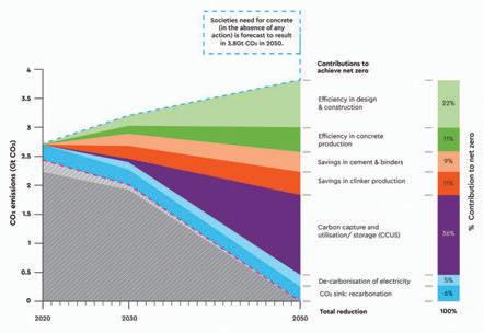
There are multiple levers that will be implemented to reduce CO 2 emissions at different stages of the whole life of cement and concrete. Our roadmap process has evaluated the role that each of these levers will play to reach net zero. The global average is presented in Figure 1.
Across the world, each lever will be implemented in accordance with local factors. For this article, we will focus on the role of design engineers, which is mostly captured in the Efficiency in Design & Construction category in Figure 1.
Role of Design Engineers in Reducing Carbon
As introduced at the beginning of this article, consideration of overall project topology, detailed element design and material specification, when seen through the criteria of minimising embodied carbon, are where design engineers can make positive contributions to decarbonisation. In Figure 1 there is a 22% contribution from efficiency in design and construction. The majority of this comes from design engineering.
At the conceptual stage, the choice of form can be optimised to reduce carbon footprint. For example, the choice of slab construction in recent years had been driven by speed and cost. This had led to solid flat slabs being the widespread solution. However, in previous decades when material costs were higher and labour cheaper, ribbed or waffle slabs were more likely
to be chosen in many countries. These structural solutions also happen to have lower embodied carbon compared with a solid flat slab – not surprisingly they are making a comeback for projects where embodied carbon is a design constraint.
Another example of topology optimisation is column spacing. There is a cost premium for larger column spacings – greater spans of beams and slabs. Clients and architects are often prepared to accept this for the added utility or aesthetics. These longer spans also come with a carbon premium. Reduced column spacings are already becoming a response to the climate agenda. Column spacing is often out of the control of the engineer, but the engineer does have a responsibility to advise and inform their architect and clients about this opportunity for embodied carbon reduction.
At the detailed design stage, element optimisation on cost time and quality has led to rationalisation of elements to facilitate ease of build. Such ease translates to cost reductions, time savings and reduced errors. It also translates to low utilisation factors – elements are larger than they need to be and
Figure 1: CO2 emissions and percentage contribution to net zero from 2020-2050
are over reinforced. At the detailed design stage, engineers need to have less rationalisation. They also need to sharpen the pencil and not include a sleep-at-night factor. The codes and standards already have load, material and safety factors.
At the specification stage, engineers need to provide the material supply chain with flexibility to provide the optimum mix that delivers the required performance with the lowest carbon.
The most significant lever available today is the use of supplementary cementitious materials (SCMs) such as Ground Granulated Blast-furnace Slag (GGBS), fly ash and ground limestone. The first two, waste materials from other industry sectors, have been used in concrete for decades and provide improved performance characteristics as well as reduced carbon footprint. Ground limestone is being included more and more in cement standards, having been used widely in continental Europe. It had, for example, become widespread in the USA in the last few years. SCMs can either be added by cement manufacturers to Ordinary Portland Cement to make blended cements (for example Portland Limestone Cement in the case of ground limestone) or they can be added by the concrete producer. In the case of Readymixed or Precast production, manufacturers may have silos for Ordinary Portland Cement and one or more SCMs.
The role of engineers is to specify what performance is required, for example – strength and durability, and perhaps set out how it is to be placed. The concrete producer can optimise the solution for reduced carbon by, for example, using SCMs, chemical admixtures and optimising aggregate grading.
Guides exist for what engineers can do, for example:
Environmental Product Declaration
• The Concrete Centre in the UK: https://www.concretecentre.com/ Resources/Publications/Specifying-Sustainable-Concrete.aspx
• NRMCA in USA: chrome-extension://efaidnbmnnnibpcajpcglclefindmkaj/https://www.nrmca.org/ wp-content/uploads/2020/09/ SpecifyingSustainableConcreteDecember2019.pdf
• In India, a guide on Blended Cements was published by GCCA India in 2022: chrome-extension:// efaidnbmnnnibpcajpcglclefindmkaj/https://gccassociation.org/ wp-content/uploads/2022/05/ Report_Blended-Cement-GreenDurable-Sustainable_11May2022. pdf
Fundamental to the ability of design engineers to quantify carbon impacts of different design decisions is having reliable comparable and consistent embodied carbon (ECO2E) data for products. This is where EPDs come in.
An Environmental Product Declaration (EPD) is an independently verified report on the environmental impact of a product throughout its life cycle. EPDs are fundamental to emerging low-carbon procurement initiatives and are a key policy for the GCCA’s global and country roadmaps.
An EPD provides objective, transparent and comparable information about a product and serves as an environmental label or declaration. The global warming potential (GWP) indicator provides a numerical value for the Embodied Carbon Dioxide equivalent (ECO2E) across the production stage for cement, and across all whole life stages for concrete.
In an EPD, the impact of the product is calculated via a Life Cycle Assessment (LCA) which conforms to the requirements of the relevant Product Category Rules (PCR). An official EPD typically consists of 2 documents: A public EPD document which summarises the environmental impact of the product (LCA results) and a private background report. Using the private background report, the finished document is verified by
an approved Programme Operator and published on one of the publicly available online platforms.
An EPD will usually remain valid for 5 years, unless there are major changes to production practices, or the environmental impacts of energy and input materials change.
The GCCA has a software EPD tool for clinker, cement and concrete (RMX and precast) which:
• Speeds up the production of the EPD and is externally recognised by EPD International as a preverified tool.
• Is widely used by members in Europe and North America and is increasingly being used in other markets, as demand for EPDs increases.
• Ensures fair and favourable application of the EPD standards (for example recarbonation).
• Enables the industry to have both consistent and cost-effective EPDs.
The Innovandi Open Challenge connects start-ups with industry. The purpose is to identify new technologies and establish agreements between start-ups and consortia of companies. Two of the six chosen start-ups from the first Innovandi Open Challenge (which primarily focused on carbon capture and utilisation) have already gone to pilot stage. The application process for the second Innovandi Open Challenge, which will focus on alternative materials for low carbon concrete, has just closed, with 70 startups applying from across the world.
economic prosperity. At a global level, resilience may even matter to our very survival.
Our built environment – homes, buildings and infrastructure – is exposed to a wide range of natural and human-made hazards and many of these hazards are exacerbated by climate change. A resilient-built environment is also a vital component to attain the UN’s Sustainable Development Goals. Concrete is the most durable of major structural materials and offers inherent resilience against many hazards. It can resist fire, wind and water. It will not rot, warp or be eaten.
The GCCA is encouraging the use of this tool by all members and nonmembers as well as academics, so that comparisons between EPDs can be consistent.
Global Innovation Platforms
GCCA has two innovation platforms which addresses the CO 2 footprint of cement and concrete. The Innovandi Global Cement and Concrete Research Network (GCCRN) undertakes precompetitive research and is made up of a consortium of 75 partners, 33 of which are industrial partners and 42 academic partner institutions from around the globe.
Let’s
Not Forget
Resilience
Resilience against hazards matters because at the individual level it ensures that our basic needs –safety, shelter, food, clean water and sanitation – can be met and that employment and livelihoods are supported. At a community and national level, resilience supports the permanence of security, justice, public health services, communications, mobility and other critical services as well as fosters
REFERENCE
Concrete also offers resilience to society by helping it recover from natural disasters. In a world in which natural disasters are increasingly common, building structures that are resilient to flooding and high wind are key components of economic, societal and environmental sustainability. Often, such buildings are built from concrete, as its durability makes it more able to survive disasters, reducing the need for (and therefore favourably affecting the cost and speed of) postdisaster reconstruction.
The design and construction industry in general as well as the concrete industry specifically, have the skills and products to deliver a more resilient-built environment which will help society resist, absorb and adapt to the many hazards to which it will be subjected.
[1] Global Cement & Concrete Association, Concrete Future: The GCCA 2050 Cement and Concrete Industry Roadmap for Net Zero Concrete. GCCA, London, 2021.
URUTER
JURUTER A
Anchor Design Based on Eurocode 2 Part 4: Design of Fastenings for Use in Concrete
Written and Prepared by:
Ng Lieu Thai
Lecturer in Civil Engineering at Swinburne University of Technology, Sarawak, researching in anchor fastening technologies.
Dr Jessey Lee
Senior lecturer in Civil Engineering at Swinburne University of Technology, Melbourne, and the Training & Development Manager at Australian Engineered Fasteners and Anchors Council (AEFAC).
Anchors, also known as fasteners, are used to connect non-structural or structural elements to buildings or infrastructure. Eurocode 2 Part 4, officially named EN 1992-4:2018, is a European Standard intended for the design of fastenings in safety-critical applications where the failure of fastenings may result in the collapse or partial collapse of a structure, posing a risk to human life and/or significant economic loss. Catastrophic failures have occurred due to various factors, such as design errors, poor installation practices and inadequate product performance.
The Malaysian construction industry is taking a proactive approach to mitigate potential catastrophic failures by adopting EN 1992-4 as the national practice for the design of fastenings in concrete. EN 1992-4 has 11 chapters.
Chapter 1 covers the general scope, including the types of fasteners, their dimensions and material, fastener loading, concrete member loading and the strength and type of the concrete. Chapter 2 lists the normative references. Chapter 3 describes the terms, symbols and abbreviations.
Chapter 4 outlines the basis of fastener design, such as required verifications, design format, partial factors for actions and resistance (ultimate limit state – static, quasistatic, seismic, and fatigue loadings, and serviceability limit state), installation of fasteners, etc. Fasteners and fixtures must have adequate durability by considering the environmental conditions for structures, as given in EN 1992-1-1, and mentioned in Chapter 5.
Dr Daniel Looi Ting Wee
Discipline Leader in Civil Engineering at Swinburne University of Technology, Sarawak. He is Chair of the Working Group for MS EN 1992-4.
Ir. Dr Adeline Ng Ling Ying
Associate Dean (Academic Practice) at Faculty of Engineering, Computing & Science at Swinburne University of Technology, Sarawak.
Chapter 6 illustrates the analysis of the forces (tension and shear loads) acting on fasteners, while Chapters 7-11 cover the verification of anchors (anchor resistance and failure mode) in terms of ultimate limit state, fatigue loading, seismic loading, fire resistance and serviceability limit state, respectively. Informative annexes follow.
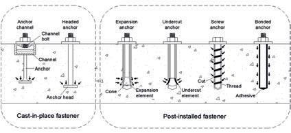
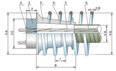
Fasteners are categorised according to their installation method: Cast-in-place or post-installed. Cast-in-place fasteners are pre-fixed in the formwork before concreting and post-installed fasteners are installed in hardened concrete with pre-drilled holes. Figure 1 shows the schematic diagrams of the types of fasteners. Cast-inplace fasteners are categorised into anchor channel and headed anchor, including headed bolt, headed stud, and internal threaded socket with head at the embedded end. The anchor channel consists of a steel profile with rigidly connected anchors and channel bolts.
On the contrary, post-installed fasteners are categorised into post-installed mechanical and bonded anchors. Postinstalled mechanical anchors are further subcategorised into friction type (expansion anchor) and mechanical interlock type (undercut anchor and screw anchor). The expansion anchor transfers the load at the contacted area between the anchor and the side wall of the drilled hole through friction force. These types of mechanical anchors are only efficient if immediate loading is required. For the undercut anchor and screw anchor, the load is transferred through a mechanical interlock cut into the concrete
during installation. The interlock of the undercut anchor occurs at the tip of the anchor. In contrast, the interlock takes place over the threads for the screw anchor. Post-installed bonded anchors transfer the load through adhesives between the anchor and the concrete. Regardless of the anchor types, the anchor-concrete interactions subjected to the external load can be tension, shear or a combination of tension and shear; these are covered in EN 1992-4. All anchors must be installed by competent and suitably experienced installers as per the manufacturer's instructions.
Scope of EN 1992-4:2018
For fastenings to be designed in accordance with EN 1992-4, the fastening product needs to be rigorously tested and independently assessed to be fit for its intended purposes of application. European Assessment Document (EAD) is the technical specification developed by the European Organisation for Technical Assessment (EOTA) that contains the methods and criteria for assessing the performance of a fastening product. Fasteners that have been assessed according to their relevant EADs, are awarded the European Technical Assessment (ETA) document which provides details of the performance characteristics of the product, such as its essential characteristics and specifications.
EN 1992-4 is only valid for anchors prequalified by the EAD (e.g. EAD 330008-03-0601 for anchor channels, EAD 330232 for mechanical anchors and EAD 330499 for bonded anchors) and relies on the characteristics stated in ETA. The design method in EN 1992-4 covers single and groups of fasteners, such as cast-in-place fasteners (i.e. headed anchor and anchor channel) and post-installed fasteners (mechanical and bonded types) installed in cracked and non-cracked concrete. For other types of fasteners, modifications to the design provisions are necessary. The design provisions in EN 1992-4 are shown below:
1. Diameter or thread size of the fastener, d
i. the minimum diameter is 6mm. It can be reduced to 5mm for fasteners used in redundant non-structural systems (See point 3).
ii. the maximum diameter is limited to 60mm for fasteners under shear loading and no limitation for tension loading.
2. Effective embedment depth of the fasteners, hef
i. the effective embedment depth of the fasteners is equal to the overall depth of the anchor embedded into the concrete, hnom. For screw anchors, the effective embedment depth is equal to 0.85(hnom – 0.5 ht – hs) according to EAD 330232. ht denotes the distance of the thread pitch, and hs is the distance between the tip of the anchor and first thread.
ii. the minimum effective embedment depth, hef ≥ 40mm. It can be reduced to 25mm for internal exposure conditions and 30mm for
CHINT SUPERIOR SWITCHES
4099
www.alphasel.com
alphamail@alphasel.com
Figure 1: Types of Fasteners and heir Load Transfer Mechanisms
other conditions for fasteners used in redundant non-structural systems (See point 3).
iii. the maximum effective embedment depth of bonded anchor is limited to 20d. For screw anchors, it is limited to 8d0 according to EAD 330232. d0 denotes the nominal drill hole diameter. There is no limitation for other anchors.
3. The design for fasteners used in redundant nonstructural systems should be designed in accordance with CEN/TR 17079.
4. Material properties of the fasteners
i. carbon steel in accordance with EN ISO 898-1 and EN ISO 898-2, EN 10025-1, and EN 10080.
ii. stainless steel in accordance with EN 10088-2 and EN 10088-3, EN ISO 3506-1, and EN ISO 3506-2.
iii. malleable cast iron in accordance with ISO 5922.
iv. valid for fasteners with a nominal steel tensile strength, fuk ≤ 1000 N/mm2. This limit does not apply to screw anchors.
5. Fasteners must be prequalified for the specific type of loading, as shown in Table 1.
6. Base material
i. only applicable for compacted normal weight concrete without fibres.
ii. the strength classes ranged from C12/15 to C90/105 in accordance with EN 206.
iii. the characteristic concrete strength, fck used in the design of fastenings shall not exceed 60 N/mm2 even if the structure uses a higher strength class. The verifications are based on the characteristic concrete cylinder strength.
Design Philosophy
In EN 1992-4, the design theories involved the calculation of the characteristic resistance of the fastener (i.e., tensile or shear capacity) for each of the potential failure modes that could occur. The failure mode with the lowest resistance will govern the fastener's design. These failure modes are briefly introduced in the following discussions.
i. Failure modes for headed and post-installed anchors
Headed and post-installed anchors under tension load exhibit several failure modes, i.e., steel failure, concrete
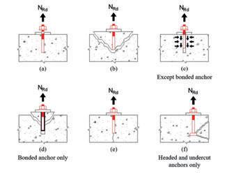
cone failure, pull-out failure, combined pull-out and concrete failure, concrete splitting failure, and concrete blow-out failure. On the other hand, the shear failure modes are steel failure with or without a lever arm, concrete pry-out failure, and concrete edge failure. Figure 2 depicts the schematic diagrams of the failure modes for headed and post-installed anchors under tension and shear loads according to EN 1992-4.
Failure modes under tension load
Failure modes under shear load
Figure 2: The Failure Modes of Headed and Post-Installed Anchors under Tension Load: (a) Steel Failure, (b) Concrete Cone Failure, (c) Pull-Out Failure (Note: Not applicable for bonded anchor), (d) Combined Pull-Out and Concrete Failure
(Note: Only applicable for bonded anchor), (e) Concrete Splitting Failure, (f) Concrete Blow-Out Failure (Note: Only required for the headed anchor and undercut anchor acting as the headed anchor if the edge distance c ≤ 0.5hef ) and Under Shear Load: (g) Steel Failure with a Lever Arm, (h) Steel Failure without a Lever Arm, (i) Concrete Pry-Out Failure, (j) Concrete Edge Failure
(i) Static and quasi-static
(ii) Fatigue loading
(iii) Seismic loading
(iv) Fire exposure
(v) Shear in the direction of the longitudinal axis1) ×
Note:
1) The design should be in accordance with CEN/TR 17080.
Table 1: Type of Loading Covered in EN 1992-4
ii. Failure modes for cast-in channel anchors
The design of anchor channels is more challenging due to their complex failure mode checks compared to headed and post-installed anchors. There are 9 possible tension failure modes and 7 shear failure modes which must be considered. The possible failure modes for anchor channels in tension and shear are shown in Table 7.4 of EN 1992-4. All components of the anchor channel, including the anchor, channel and channel bolt, must be checked for steel failure. Anchor channels also exhibit concrete-related failures similar to those of headed and post-installed anchors, such as concrete cone failure, pull-out failure, concrete splitting failure, and concrete blow-out failure under tension load. The failure modes under shear are concrete pry-out failure and concrete edge failure.
iii. Supplementary reinforcement
In addition, supplementary reinforcement can be provided surrounding the fasteners, but the supplementary reinforcement must be designed to resist the total load. Thus, the verification of concrete cone failure under tension load and concrete edge failure under shear load can be omitted. However, two additional verifications are required: Steel failure and anchorage failure of supplementary reinforcement. Supplementary reinforcement is generally ideal for cast-in-place fasteners, i.e., headed anchor and anchor channel. Although it may be considered for post-installed fasteners, it may not be practical, given that the supplementary reinforcements are embedded in the concrete.
iv. Proposed simplification for the anchor design
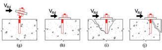
The lack of understanding of the design solutions for anchors based on EN 1992-4 can pose a challenge for practising engineers who are new to anchor design. To address this issue, the authors have recently developed a two-dimensional (2D) design tool that can estimate the design tensile and shear capacities of post-installed mechanical and bonded anchors (Ng et al. 2022a & 2022b). These design tools have been demonstrated for a single anchor in C30/37 cracked concrete with a member thickness of 125mm. These design tools are expected to be useful for quickly estimating anchor tensile and shear capacities, as well as their failure modes.
A design example is described here to facilitate using the 2D design tools. A single 8mm diameter mechanical anchor is designed in a C30/37 cracked concrete with a member thickness of 125mm. The considered anchor embedment depth, hef is 50mm and the edge distance, c is 50mm. From Figure 3, the design tensile capacity is 4.4 kN, governed by concrete cone failure. The design shear capacity is 4.7 kN, governed by concrete pry-out failure.
The design tool is developed for C30/37 concrete grade. For other concrete grades, a modification factor, ∅ f ck (as indicated in Table 2) should be multiplied with the capacity obtained from the graph. The limitation of the concrete thickness will be further discussed in subsequent publications.
Figure 3: Examples of the Design Tool for (a) Design Tensile Capacity and (b) Design Shear Capacity of Post-Installed Mechanical Anchor for 8mm Anchor Diameter
Table 2: Modification Factor, ∅ f ck
builders, academics, code-drafters who had experience in Australia/Singapore and the Department of Standards Malaysia. The authors appreciated the opportunity given by the organising committee of the 15th International Conference on Concrete Engineering & Technology (CONCET2022) to acknowledge the authors’ work as the best paper award.
Conclusion and Future Outlook
In summary, steel-to-concrete connections in structures mainly depend on using fastened anchors. Failure of these anchors may potentially cause collapse failure of structural or non-structural members, which may lead to human casualty. Additionally, it can result in the disruption of facilities, buildings and business losses. Therefore, it is imperative to design fasteners according to international best practices and to use only qualified anchors for safetyrelated applications. The Malaysian version for the design of fastenings in concrete, MS EN 1992-4, and its National Annex, accompanied by a commentary handbook, are targeted to be completed and launched in the 11th International Conference on Advances in Steel Structures (ICASS’2023) in December 2023.
Acknowledgement
The authors would like to thank the technical input provided by the Working Group members drafting the MS EN 19924, which consisted of members representing stakeholders from the anchor fastening suppliers, consulting engineers,
REFERENCES
[1] European Assessment Document 2018, Anchor channels, EAD 33000803-0601, European Organisation for Technical Approvals (EOTA).
[2] European Assessment Document 2018, Bonded Fasteners for Use in Concrete, EAD 330499-01-0601, European Organisation for Technical Approvals (EOTA).
[3] European Assessment Document 2019, Mechanical Fasteners for Use in Concrete, EAD 330232-01-0601, European Organisation for Technical Approvals (EOTA).
[4] European Standard 2018, Design of Concrete Structures – Part 4: Design of Fastenings for Use in Concrete, BS EN 1992-4:2018, British Standard Institution.
[5] Ng, LT, Looi, DTW, Lee, J & Ng, ALY, 2022, 'A Simplified Design Solution for Shear Capacity of Post-Installed Anchors Encompassing All Failure Modes in EC2-4 (2018)', 15th International Conference on Concrete Engineering and Technology (CONCET2022), 6-7 Dec, Kuala Lumpur, Malaysia.
[6] Ng, LT, Wong, ESH & Looi, DTW 2022, 'Feasible Design Tensile Capacity of Post-Installed Anchors Based on the New Eurocode 2: Part 4 (2018)', in S Belayutham, CKI Che Ibrahim, A Alisibramulisi, H Mansor, M Billah (eds), Proc. of the 5th International Conference on Sustainable Civil Engineering Structures & Construction Materials. Lecture Notes in Civil Engineering, Springer, Singapore, vol. 215, pp. 819-836.
Joints Dilemma in Concrete Floor Slabs
Written and Prepared by:
Dr Lim Eng Hock (Zack)
Zacklim Flat Floor Specialist Sdn. Bhd., Group Managing Director of Zacklim Group of Companies.
Ideally, concrete floors and pavements should be constructed without joints to avoid problems such as unevenness, spalling and operational slowdowns which require frequent repairs and cause service interruptions and downtime. However, joints are inevitable and necessary for the following reasons:
1. Concrete needs to have the freedom to shrink, expand and contract as it dries and experiences temperature changes.
2. It is not feasible to complete a flooring project in a single day, therefore making day joints unavoidable.
3. Joints are required to release tensile and compressive stresses when concrete shrinks during the drying process.
4. To isolate different structural elements such as columns and machine foundations.
5. Joints help control cracks. Although they cannot eliminate them, they can minimise their occurrence.
Four types of joints (construction, contraction, expansion and isolation) are necessary to avoid and mitigate unexpected cracking. The challenge is in determining and selecting the appropriate type of joints and the spacing between each joint to eradicate or reduce random cracking within floor panels. However, there is still much uncertainty and confusion with regards implementing the correct type and specification of joints to be designed. Below are common types of joints dilemma.
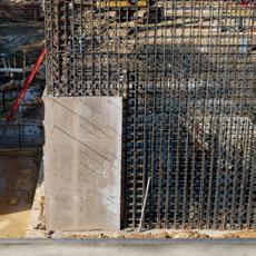
Construction Joints
The points at which slabs are terminated at the end of the day or where two successive panels meet are referred to as construction joints or day joints; these serve the purpose of stress relief. Construction joints are frequently utilised in slabon-grade, where dowels are inserted for transferring loads between panels, whereas keyed joints are suitable for light loading slabs but are not recommended for heavy loading.
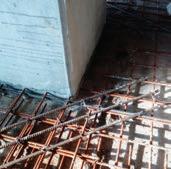
However, continuous reinforcement is employed in slab on piles and elevated slab where reinforcement is used to transfer load and assist to maintain the joints tight.
The size and length of dowel bars to be specified at construction joints depends on slab thickness as extracted from ACI 302.1R: Guide for Concrete Floor & Slab Construction. Refer to Table 1.
Table 1: Dowel size, length and spacing based on slab thickness (ACI 302.1R)
As stated in Table 1, the recommended length for round dowel bars is between 400 and 450mm. Some designers specify dowel sizes that are either too small or excessively long (up to 900mm in length) or wrongly propose both. It is important to note that longer dowels are not necessarily better as, if placed at an angle and not properly aligned horizontally to the edge, longer dowels can hinder free sliding between the 2 slabs. This can lead to cracking as the excessive length locks the slabs together.
Another challenge in protecting construction joints is about potential spalling at the edges due to continuous heavy wheel loads. Traditionally, angle irons are embedded in both sides of the joints to protect the edges from damage. However, this approach is not recommended as improper level installation can negatively impact the smooth passage of wheels over the joints.
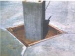
A third method involves designing a lip that uses a single angle iron on one side of the slab to prevent spalling. After casting the adjacent panel, a thin piece of concrete (approximately 50mm x 50mm) is created on top of the angle bar. This thin piece of unreinforced concrete which is weak, will quickly be prone to cracking and spalling (Figure 1).
Hence, it is advisable to substitute the conventional angle iron bars with armoured joints. These consist of flat bars that are 10mm thick, 25-50mm high and 3 meters in length. When installed correctly, armoured joints offer greater efficiency and pose fewer issues. When designing construction joints with armoured joints, it is also crucial that designers consider the size, length and type of steel bar, round not deformed, to be specified. To address this, the recommended approach is to utilise the latest plate dowels.
Contraction Joints
A contraction joint, also known as a control joint or saw-cut joint, is created by cutting the concrete slab using diamond saw blades. This process forms a weakened plane below the saw-cut which helps regulate and control cracking caused by concrete shrinkage, expansion and contraction, thereby preventing random cracks.
For light-duty slabs or pavements, load transfer across contraction joints is not a major concern because aggregate interlock across the resulting crack will bear the load. However, if the joint opening exceeds 1mm, the load transfer may become ineffective and dowels will need to be installed. On the other hand, for heavy vehicles, dowels are placed to ensure vertical alignment and flatness across the two slabs to avoid faulting which can damage wheels by hitting a higher edge and causing the spalling of the concrete edge.
According to the American Concrete Institute (ACI), it is generally recommended that contraction joint depth should be a minimum of one fourth of the concrete depth and the spacing should be between 24 and 36 times the slab thickness. For example, if the slab thickness is 100mm, the suggested expansion joint spacing should be between 2.4m and 3.6m. While this guideline helps mitigate random cracks, applying it strictly may result in an excessive number of contraction joints for large floors. For slabon-grade applications, recommended contraction joint spacing can be 6m x 6m or larger, depending on the type and design of reinforcement used. In some cases, such as car park floor panels with contraction joints of up to 16m x 16m, the use of steel fibres was successfully implemented with proper work practices. Another criterion to consider is that the width-to-length ratio of each panel should not exceed 1:1.25, as a conservative measure.
With regards to suspended or elevated slabs, there is some ambiguity about the necessity of providing contraction joints. It is well-known that suspended slabs are designed to crack and inducing control cracks through saw cuts may be redundant, as the reinforcement is continuous. Accidentally cutting the reinforcement is prohibited and shallow cuts may not be effective. Generally, hairline cracks on elevated slabs are considered normal, as these are typically caused by drying shrinkage and the inherent restraint of the slab, unless there are specific reasons to suggest otherwise.
Expansion Joints
Expansion joints are essential to allow slabs to accommodate movement caused by temperature changes, particularly for extremely large internal panels and normal external pavements. In practical terms, expansion joints are typically unnecessary for slab-on-grades, as any stress or movement that occurs will be relieved via all the contraction joints present.
For large floor slabs, it is recommended to provide an expansion joint approximately every 30m to 50m to relieve stress in continuously reinforced slabs. At the expansion joint, dowels (half its length coated with a debonding agent) are inserted into one side of the slab. The thickness of the filler board at the expansion joint is a consideration. Typically, filler boards of up to 25mm are specified to facilitate the expansion and contraction of the slab. This thickness is commonly recommended in cold countries where temperature variations between seasons can be significant, causing the joints to contract and expand.
However, in tropical climates such as ours, the need for such thick filler boards can be significantly reduced or even eliminated. This is because new concrete shrinks as it dries, resulting in wider joint openings. Depending on the concrete mix design, all the expansion joints may open up to 20mm. If an expansion joint is initially designed with a 25mm filler board, combined with 20mm shrinkage, the final opening will be 45mm wide. Such a wide opening will lead to maintenance and operational issues. Therefore, it is advisable to reduce the thickness of the filler boards or consider alternative approaches to avoid excessive joint openings which can affect the smooth operation and maintenance of the floor and vehicles.
According to information found on the internet, it has been suggested that expansion joints should be spaced no more than 2-3 times the total width of the slab in feet, considering the slab thickness in inches. For example, for a 5-inch-thick slab, the suggested spacing for expansion joints would be 10-15 ft. However, this statement is incorrect, as the recommended spacing is more suitable for contraction joints rather than expansion joints. This speaks for the necessity to ensure industry standards are used for the design rather than random internet search results.
Figure 1: A lip at the edge of joint
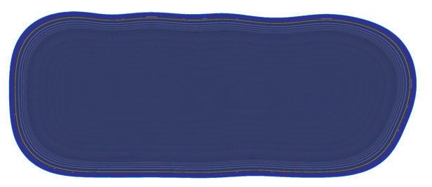
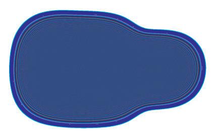
Isolation Joints
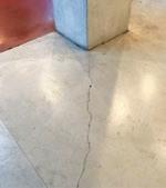
Isolation joints facilitate both vertical and horizontal movement between adjacent structures, enabling them to move independently. Examples of isolation joints include round isolation joints (Figure 2) or square isolation joints (Figure 3), which are commonly used to separate a slab-ongrade from columns.
Hence, when constructing a slab-on-grade, it is important not to connect the floor panels directly to columns, ground beams or machine foundations. Instead, a compressible board should be installed around these
fixed structures to allow for stress relief and to prevent unwanted binding with the slab. Differential settlement between the fixed structures, such as columns and beams in relation to the floor slab due to lack of ground compaction, will promote cracking.
Since it is not possible to isolate the slabs from the columns in the case of elevated slabs, it is common to observe re-entrance corner cracking (Figure 4). To mitigate the occurrence of such cracks, it is recommended to place diagonal bars at all four corners of the column (Figure 5).
Summary
Improperly designed and constructed joints can be more detrimental and problematic than shrinkage cracks. Failed joints can lead to spalling under traffic, impacting the functionality and daily operations of a surface. While shrinkage cracks may primarily affect the aesthetic appearance of the floor, failed joints can significantly disrupt operations as well as prove challenging to repair and maintain and, unless one knows the correct repair method, the problem may continuously reoccur.
Even with careful design, a thorough understanding of concrete behaviour and adherence to good workmanship practices, it is impossible to completely prevent cracks. However we can mitigate their occurrence or reduce larger floor cracks into hairline cracks by implementing appropriate design measures and construction techniques.
This is the joints dilemma.
REFERENCE
[1] ACI 302.1R: Guide for Concrete Floor and Slab Construction. 2015. Reported by ACI Committee 302. American Concrete Institute.
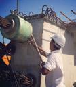
Managing Director of Safe Asbestos Solutions Sdn. Bhd. which specialises in asbestos survey, analysis, consultancy, training, removal and disposal services.
Asbestos, a naturally-occurring mineral fibre, had been used in more than 3,000 construction materials and manufactured products. It was commonly found in heating system insulation, decorative spray-on ceiling treatments, vinyl flooring, cement roofing and ceiling sheets and a variety of other materials such as electrical insulator in older buildings or houses.
Why was asbestos so commonly used in the past? This was because asbestos had one of the best material characteristics and it was cheap; asbestos was durable, resistant to fire, heat, electricity, water and chemical. It could also absorb sound.
Microscopic asbestos fibre cannot be seen, has no smell or taste and it does not cause any immediate symptom when one is exposed to it.
Why is Asbestos Hazardous?
When asbestos-containing materials (ACM) are disturbed, they become health hazards. Commonly known illnesses attributed to prolonged exposure to ACM are asbestosis, mesothelioma and lung cancer.
There is no safe level of exposure to airborne asbestos fibres. This is why medical, environmental health and regulatory organisations stress the need to protect health by minimising exposure to airborne asbestos fibres.
Generally, the worst effects are felt when a person is exposed to high concentrations of asbestos and/or is exposed on a regular basis over a long period of time.
Managing Risks of Asbestos Exposure
To determine the presence of ACM on your premises, you would need to conduct an asbestos survey and develop an asbestos register which must be done by a
competent surveyor. Once identified, it must be labelled and monitored on a regular basis to check for any breakage, cracks or wearing out of the ACM and the potential release of asbestos fibres.
A short-term remedy would be to apply paint over the ACM items, such as ceiling boards, panel boards or roofing sheets in order to suppress any potential release of airborne asbestos fibres.
In Case of Accidental Exposure
The following actions are recommended:
1. Do NOT dust off clothing. Instead, wet or dampen them.
2. Remove clothing with care. Clothing should be removed in an inside-out manner so as to contain the asbestos fibres inside.
3. When possible, quickly take a proper shower. Otherwise, wipe your body clean with a damp towel.
4. Clean the shower area thoroughly after use.
5. Any material and clothing that is contaminated must be collected and packed in a sealed bag for disposal accordingly.
6. Do NOT put contaminated clothing inside a washing machine as this will result in contamination of the washing machine.
7. NOTE: When exposed to material containing asbestos, stay calm and act responsibly. Avoid spreading the asbestos fibres and ensure that any exposure is to be kept to minimum.
ALWAYS REMEMBER: Do not disturb or damage any ACM.
• DOSH Asbestos Removal Guidelines 2017 (**DOSH approval to be obtained for removal work)
• OSH Act 2022 (Act A1648) Section 18(b) – due for implementation mid-2023
Asbestos rock after mining process
Asbestos (chrysotile) fibres under microscope
Introduction of MS EN 1991-2, MS EN 1992-2 and Related Eurocodes in Bridge Design & Construction
Written and Prepared by:
The Civil & Structural Engineering Technical Division (CSETD) of IEM organised a 2-day course titled Introduction of MS EN 1991-2, MS EN 1992-2 and related Eurocodes in Bridge Design & Construction, on 8-9 November 2022, at Dorsett Grand Subang Hotel, Selangor. It was attended by 259 participants.
The speaker was Ir. Teh Tzyy Wooi, who had obtained his BSc from UKM and MSc in Bridge Engineering from Surrey University. In 2009, he was awarded the IEM Young Engineer Award.
With more than 22 years’ experience in design, construction and maintenance of bridgework and
underground structures, he is also an independent checker for major road and railway bridges. He has designed some major long span stayed-cable bridges overseas.
Ir. Teh is the Director of H&T Consulting Engineers Sdn. Bhd. He is actively involved in Malaysian Standard Drafting Committee for MS EN in bridge-related codes. Malaysia developed the MS EN 1991-2 and 1992-2 and the related National Annex (NA) for bridge design after withdrawal of BS5400. The first version of NA was published by the Department of Standards Malaysia (JSM) in 2010.
Ir. Lo Seng Ling
Photo session with the Guest of Honour, Encik Shaharul Sadri Alwi (Director General of Department of Standards Malaysia) and event sponsorship partners
Ir. Teh started Day One by highlighting the important items in National Annex to MS EN 1990:2002 (Rev). There was a need for consistency between the harmonised technical specifications for construction products and technical rules for works. Furthermore, all information accompanying the CE Marking of construction products which referred to Eurocodes, should clearly mention which Nationally Determined Parameters had been taken into account.
The implication of MS EN to concrete bridge design in terms of concrete section dimension, reinforcement and pre-stressing were thoroughly explained. Concrete cover to reinforcement, which was the distance from the outer surface of the reinforcement to the nearest concrete surface, should satisfy the minimum requirements in respect of bond and durability, and followed the deviation to be expected in execution (in Section 4.5). Concrete cover for bond was to transmit bond forces safely and to ensure adequate compaction, the minimum cover could be determined from Table 4.1 in MS EN. Concrete cover required for durability in different environmental conditions were set out in Table 4.3 in MS EN, derived from BS8500.
The compressive stress in the concrete should be limited to avoid longitudinal cracks, micro-cracks or high level of creep, where it could result in acceptable effects on the function of the structure. Tensile stresses in the reinforcement should be limited to avoid inelastic strain, unacceptable cracking or deformation.
On Day Two, Ir. Teh continued his presentation with bridge bearing design in accordance with EN1337 and EN15129 (European Standard). Bearings were elements which allowed rotation between two members of a
structure, transmitted the loads defined in the relevant requirements and prevented displacements (fixed bearings), allowing displacements in only one direction (guided bearings) or in all directions of plane (free bearings) as required.
The common types of bearings were elastomeric bearing, pot/spherical bearing, roller bearing, cylindrical bearing and guide bearing. The designs of the various bearings should be based on serviceability and/or ultimate limit state depending on the safety classification of the limit state in consideration. The design rules for each type of bearing were presented in detail.
Afterwards, the pre-stressing system used in bridge construction was discussed, in which it should comply with the European Assessment Document (EAD) developed by the European Organisation for Technical Assessment (EOTA). The tests for the pre-stressing system should include static load test, fatigue load test, load transfer test, friction test, deviation and deflection, assessment assembly, tendon protection level and other relevant tests.
At the Q&A session which followed, there were several queries and comments from participants which Ir. Teh answered and discussed in detail. A token of appreciation was then presented to the speaker and the course ended at 6.00 p.m.
Ir. Teh with Ir. Dr Anizahyati Alisibramulisi and Dr Chua Yie Sue (the moderators), participants and event secretariat
Presentation session at Dorsett Grand Subang Hotel, Selangor
Seminar on “CIDB Act 520 Amendment 2021, Construction Industry Standard CIS 22:2021 & CIS 23:2021” and “Falsework Design and Testing of Falsework Structures”
Written and Prepared by:
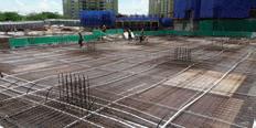
The Civil & Structural Engineering Technical Division (CSETD), IEM, organised a half-day seminar titled CIDB Act 520 Amendment 2021, Construction Industry Standard CIS22:2021 (Safe Use of Scaffolding in Construction) & CIS23:2021 (Safe Use of Falsework in Construction) and Falsework Design & Testing of Falsework Structures on 15 March 2023. There were 61 participants (physical and virtual).
The first speaker was Ir. Lee Kee Bau, the Technical Director of a company dedicated to temporary work for construction. He has more than 25 years’ experience in temporary work for construction. He is an active technical committee member of the Construction Industry Development Board (CIDB) for CIS22 and CIS23 and chairman of the technical committee of Department of Standard Malaysia (DSM) for Malaysia Standard for Steel Product Including Scaffolding & Falsework and a committee member of the working group of Malaysia Standard for Falsework & Scaffolding in DSM too.
The second speaker was Ir. Dr Lim Boon Tiong, Managing Director of Meinhardt Malaysia, who graduated with a PhD in Structural Engineering from University of Glasgow. He has more than 30 years’ experience in civil & structure design, including high-rise buildings, road works, viaducts, geotechnical & earth slope, drainage, sewerage and water supply works.
CIDB Act 520 (Amendment of Fourth Schedule) Order 2021 was enforced on 13 September 2021. It covers scaffolding and falsework materials used in the construction industry and the materials shall be complied with the construction industry standard CIS22:2021 (Scaffolding)
& CIS23:2021 (Falsework). The manufacturers, suppliers, contractors, professional engineers for temporary work (PETW) and consultant engineers shall ensure the compliance of the Act 520, CIS22 & CIS23 for supply, design and use of scaffolding & falsework in construction.
CIS22:2021 covers the use of scaffolding complying with MS1462 series of Malaysia Standards while CIS23:2021 covers the use of falsework complying with British Standard BSBS5975, BSEN12812, BSEN12813, BSEN16031, BSEN1065 and compliance with Malaysian Acts and Regulations. All scaffolding systems shall be tested by an independent third-party certification body (recognised by CIDB). Each scaffolding component shall be marked on the body, either embossed or waterproof sticker, with the name of manufacturer/supplier, year of manufacture, standard referred and CIDB PPS (Perakuan Pemantuhan Standard) number. The contractor shall engage PETW to prepare and endorse the drawings and design calculation of scaffolding and falsework and submit to DOSH. The contractor shall also properly plan and conduct HIRARC to ensure the safety of the falsework before construction starts. After the scaffolding is received at the construction site, visual inspection shall be carried out to identify the damage on the scaffolding. Damaged scaffolding shall be removed from the construction site. The erection, modification, maintenance and dismantling of the scaffolding shall be performed by a competent scaffolder under direct supervision of a designated person (DP). This erected scaffolding shall be inspected and recorded by the DP before use.
Proprietary falsework systems are used in almost every construction site in Malaysia. Workers erecting
Ir. Lo Seng Ling
Ir. Dr Kwong Kok Zee
Nehemiah Prestress
falsework systems may have little or no formal training and engineers often rely on suppliers for technical advice on their design and safe use. The failure of falsework structures has serious consequences and it is therefore essential that the falsework designer understands the basic design checks for structural strength and stiffness of individual members and the overall stability of falsework structures.
Falsework is a temporary structure that supports the permanent structure before the permanent structure is deemed to be self-supporting. It also acts as a temporary working platform, storage area during the construction stage. Design loads for falsework shall include self-weight, impose load from wet concrete, impact due to free flow height of wet concrete, eccentricity due to imperfection of joints, wind load, construction load and notional load from BS5975. The falsework shop drawings shall include the following information:
• Notes on the sizes of all load carrying elements, including soffit bearers, joists, transverse and longitudinal bracing members and connections.
• Specify the assumed soil bearing values for pad or footing support.
• Specify the required welding standard.
• Specify the grade, E-value, type of structural composite timber.
• Specify the trade name and rating if the falsework should be a proprietary shoring system.
• Specify the design controlling dimensions including length and spacing of beams, locations and spacings of posts, overall height of bents, height between connections in diagonal bracing and other dimensions that are critical to the design.
The Strand, Kota Damansara 47810 Petaling Jaya
Selangor Darul Ehsan
Tel : 603 6142 6638
Fax : 603 6142 6693
Email : enquiry-pt@nehemiah-grp.com
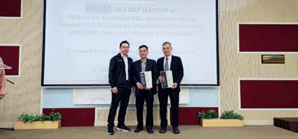
All shop drawings shall be endorsed by a PETW (with a Practicing Certificate). At the end of the seminar was a Q&A session, followed by the presentation of tokens of appreciation to Ir. Lee and Ir. Dr Lim by Ir. Ng Beng Hooi, the Secretary and Treasurer of CSETD. The seminar ended at 1.30 p.m. with a photo session.
Nehemiah-OVM
Nehemiah A member of the Nehemiah Group
No. 45-3, Jalan PJU 5/20
Nehemiah Prestress Sdn Bhd (1140945-A)
Figure 1: Ir. Ng Beng Hooi Presenting Tokens of Appreciation to Ir. Lee Kee Bau and Ir. Dr Lim Boon Tiong
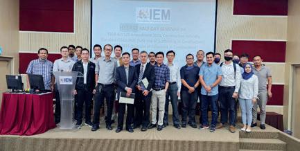
Figure 2: Photo Session with the Moderator, Speakers and Participants
Impactful Engineering Experience! IEM Technical Visit to MRT2 Hospital Kuala Lumpur Station
Written and Prepared by:
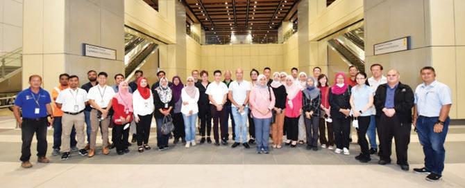
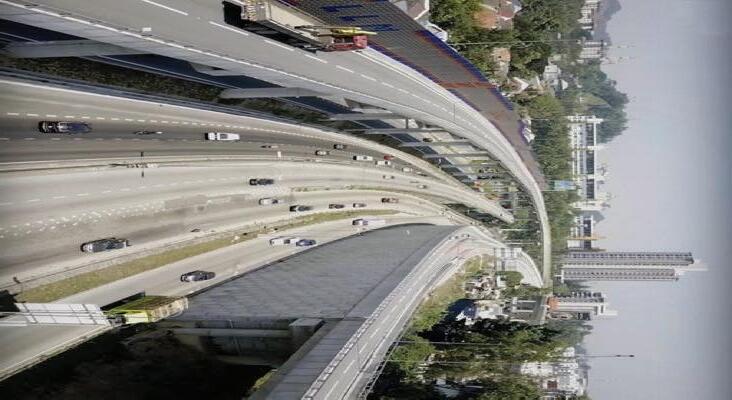
IEM’s Women Engineers Section (WES) and Mechanical Engineering Technical Division (METD) organised a technical visit to MRT2 Hospital Kuala Lumpur Station (HKLS) on 20 December, 2022 in collaboration with MMC GAMUDA KVMRT (T) Sdn. Bhd. The MRT Putrajaya Line or MRT2 is the second Mass Rapid Transit (MRT) line and the fourth fully automated, driverless rail system in the Klang Valley. It is a part of the larger rail transport network in Kuala Lumpur, known as the Klang Valley Integrated Transit System.
With 36 stations (including 9 underground) and measuring 57.7km in length (of which 13.5km is underground), the MRT Putrajaya Line serves a corridor of 3 million people from Sungai Buloh to Putrajaya through the KL city centre. It connects Bandar Sri Damansara, Kepong, Batu, Jalan Sultan Azlan Shah, Jalan Tun Razak, KLCC, the Tun Razak Exchange, Kuchai Lama, Seri Kembangan and Cyberjaya. Phase One, from MRT Kwasa Damansara to MRT Kampung Batu, started operations in June 2022; Phase Two from Kampung Batu Station to Putrajaya Sentral was fully running in March 2023.
The MRT line offers many benefits. First is convenience as Malaysians can experience stress-free travel to the city centre, avoiding traffic congestion and the need to hunt for parking places at their destination. Also, rail travel is considered a lot safer than road travel. The MRT can carry large numbers of passengers, thereby reducing the number of cars on the road and contributing to less traffic congestion. The MRT line can also boost the economy of areas along its route as reliable transportation is a catalyst for development.
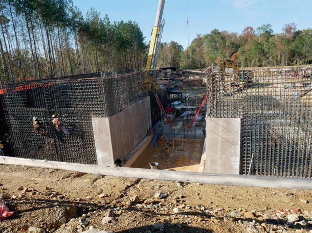
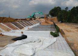
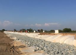
During the technical visit to HKLS, participants were briefed on the various features and technical highlights of the underground station, including unique construction challenges. The station is located between Jalan Kuantan and Jalan Tun Razak. Its strategic location, opposite Hospital KL, Istana Budaya (National Visual Art Gallery) and nearby Taman Tasik Titiwangsa, provides connectivity to Hospital KL via an underpass to Entrance A and Istana Budaya via Entrance B. It was built at a depth of 30 metres from ground level to the base of the station box and has three levels – concourse, plant-room and platform. It is also the widest and simultaneously the shortest in length of all the underground stations.
One of the biggest challenges faced when constructing HKLS was its complex ground geology. Ground Pretreatment works such as rock probing and compaction grouting were done to prevent complications of geological interface and faults. The construction also required extensive utilities and services monitoring to avoid any disruption to the vicinity. All utilities and services were protected to ensure that no disruptions occurred during its construction. The underpass below Jalan Tun Razak, also known as Adit A, is the longest underpass route and is the only station with travellators to provide a seamless connection to the hospital.
Ms. Sakinah Ab Halim
Figure 1: Ms. Sakinah Ab Halim talking about Interface Management Roles in MRT2
Distribution, Telecommunication Systems and Automatic Fare Collection.
The technical visit gave participants exposure to the design and construction of the HKL underground station and the various challenges encountered. It also gave them a first-hand experience of the station prior to the actual line-wide opening in March 2023.
Participants also learnt about Mechanical & Electrical (M&E) services and Interface Management roles throughout the MRT2 project. M&E services included electrical systems, environmental control systems, fire detection/protection systems, plumbing, tunnel ventilation systems, vertical transportation systems (lifts and escalators) as well as building management systems and electronic access control systems to manage and monitor all system equipment serving the building.
Interface Management roles covered capturing railway system requirements and coordination works as per contract requirements between Civil & Structure, Architectural Building Works & Finishes, Mechanical & Electrical and Railway Systems Works Package Contractors in the design, construction, testing and commissioning stages. The Railway Systems Works Package Contractors involved were Signaling and Train Control System, Platform Screen Doors, Integrated Control & Supervisory System and Computerised Maintenance Management System, Electric
and
and
Trains
Depot Equipment, Trackwork
Maintenance Vehicles and Work Trains, Power Supply &
Figure 2: Group photo of IEM representatives from WES, METD and MMC Gamuda as well as other participants
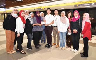
Figure 3: WES Chairperson Ir. Noorfaizah presenting a token of appreciation to HKLS Project Manager Chew Say Hong. With them are IEM participants and HKLS site teams.
Awards for 215 Malaysian Inventors at IPITEx
Written and Prepared by:
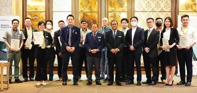
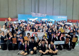
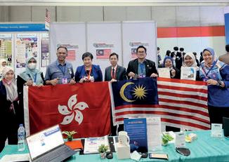
At the Thailand Inventors’ Day 2023, 215 inventors from Malaysia won 10 Gold, 16 Silver, 40 Bronze and more than 10 Special Award medals presented by Poland, Hong Kong, Britain, Singapore, Indonesia, The Philippines, Egypt and Japan, at the Bangkok International Intellectual Property, Invention, Innovation & Technology Exposition (IPITEx) 2023 on 1-6 February 2023.
The inventors were from UniKL, UUM, UKM, UiTM, UTHM, UPSI, Politeknik Sultan Abdul Halim Mu’adzam Shah, Kolej Vokasional Sungai Petani 1, Kolej Vokasional Kulim, Sbp Integrasi Temerloh, Sekolah Jenis Kebangsaan (T) Ladang Mount Austin, SM Sains Bagan Datoh Bagan Datuk Perak, Sekolah Menengah Imtiaz Yayasan Terengganu Kuala Terengganu, SMK Sultan Badlishah, SK Seksyen 19 Shah Alam, SMK Ulu Tiram, SMK Seksyen 7, Sekolah Kebangsaan Jalan U3, SMK Seri Panching Kuantan and Maahad Integrasi Tahfiz Selangor Alam Impian. The youngest team comprised 7-year-old students from SJKC Ying Wah.
According to the head of delegation from MINDS, Prof. Dr Leong Wai Yie, the international judges, visitors and Encik Hairuddin from the Embassy of Malaysia in Bangkok who attended the exhibition, were impressed with the Malaysian inventions. The event saw over 1,000 inventions from more than 24 countries and over 500 presentations. The Malaysian teams also had the opportunity to exchange knowledge and experience with other international inventors.
IPITEx 2023 was hosted by the National Research Agency (NRC), Thailand’s Ministry of Higher Education to promote and support the use of inventions and innovations of international inventors and researchers. The aim was also to motivate and nurture new generations of inventors.
This year’s event featured exhibits on medicine and public health, medical technology, health products, modern agriculture, environment/water/power and electricity/ green technology, building/construction, education, household items, robotics, information, communication and technology (ICT) and manufacturing processes.
Ir. Prof. Dr Leong Wai Yie
Delegates from MINDS
Politeknik Sultan Idris Shah received the International Invention Award from Hong Kong Student Invention Patent Program, HKSIP, Hong Kong
Kepada Semua Ahli,
Tarikh: 19 Jun 2023
SENARAI CALON-CALON YANG LAYAK MENDUDUKI
TEMUDUGA PROFESIONAL TAHUN 2023
Berikut adalah senarai calon yang layak untuk menduduki Temuduga Profesional bagi tahun 2023.
Mengikut Undang-Undang Kecil IEM, Seksyen 3.8, nama-nama seperti tersenarai berikut diterbitkan sebagai calon-calon yang layak untuk menjadi Ahli Institusi, dengan syarat bahawa mereka lulus Temuduga Profesional tahun 2023.
Sekiranya terdapat Ahli Korporat yang mempunyai bantahan terhadap mana-mana calon yang didapati tidak sesuai untuk menduduki Temuduga Profesional, surat bantahan boleh dikemukakan kepada Setiausaha Kehormat, IEM. Surat bantahan hendaklah dikemukakan sebulan dari tarikh penerbitan dikeluarkan.
Ir. Prof. Dr Zuhaina binti Zakaria Setiausaha Kehormat, IEM
PERMOHONAN BARU
Nama Kelayakan
KEJURUTERAAN AWAM
CHANG KUEH CHIN BE HONS (UTM) (CIVIL, 1990)
NOOR IRMAYATI BINTI ISMAIL BE HONS (UTP) (CIVIL, 2007)
NORASIMAH BT MAT NOR BE HONS (UTM) (CIVIL, 2005)
NURFITRI BINTI SENIN BE HONS (UKM) (CIVIL AND ENVIRONMENTAL ENGINEERING, 2005) ME (UKM) (ENVIRONMENTAL, 2014)
WAN ADAWIAH BINTI WAN ASMAN
SHUKOR BE HONS (MALAYA) (CIVIL, 2008)
WASLIMAN BIN SAPON BE (UTM) (CIVIL, 2004)
KEJURUTERAAN PEMBUATAN
MOHD NAZIF BIN MOHD BAHARUDDIN BE (UKM) (MECHANICAL AND MATERIALS ENGINEERING, 2000) ME (UTHM) (MECHANICAL, 2012) PhD (UniKL) (2022)
MOHD NIZAM BIN MOKHRI BE (UKM) (MECHANICS AND MATERIALS, 2000) ME (UniKL) (GREEN AND ENERGY EFFICIENT BUILDING, 2014)
PERMOHONAN MENJADI AHLI KORPORAT
Nama Kelayakan
KEJURUTERAAN AWAM
MOHD REDZUAN BIN AB RAHMAN BE (UTM) (CIVIL, 2005)
TAN YI HONG BSc (STATE UNIVERSITY BUFFALO) (CIVIL,17)
KEJURUTERAAN ELEKTRIKAL
MOHAMAD FADLI ADLIZAM BIN SARMUJI BE HONS (UTM) (ELECTRICAL, 2014)
KEJURUTERAAN PEMBUATAN MOHAMED NAZRIN BIN MD NAZIR BE (UM) (MECHANICAL,2013)
PERPINDAHAN AHLI
No. Ahli Nama Kelayakan
KEJURUTERAAN KIMIA
105251 MOHAMAD FIRDAUS BIN AZIZAN BE HONS (UTM) (CHEMICAL, 2015)
42348 TAN JIUNN KET, FREDERICK BE HONS (UMS) (CIVIL, 2011)
94355 TAN KOK CHIN BE (UMP) (CIVIL, 2009)
41991 TING YING BE HONS (UKM) (CIVIL AND STRUCTURAL ENGINEERING, 2009
KEJURUTERAAN ELEKTRIK
62106 LOOI TINK HUEY, ALEX BE HONS (ASIA PACIFIC UNIVERSITY) (ELECTRICAL AND ELECTRONIC, 2015)
104336 ONG HAN BIN BE HONS (UTP) (ELECTRICAL AND ELECTRONICS, 2019)
81286 PUJAYANTHA KUMAR A/L MANOHER BE HONS (UNITEN) (ELECTRICAL, 2013)
71510 TAN WEI TING BE HONS (MALAYA) (ELECTRICAL, 2015)
79603 YONG KONG WOON BE HONS (UNITEN) (ELECTRICAL POWER, 2018)
KEJURUTERAAN ELEKTRONIK
35605 AHMAD SHAFIQ MIRZA BIN MANSOR BE HONS (MULTIMEDIA UNIVERSITY) (ELECTRONIC MAJORING IN COMPUTER, 2005)
73360 ONG CHONG GENE BE HONS (RMIT) (ELECTRONIC, 2007)
KEJURUTERAAN MEKANIKAL
30788 AZMIL BIN MD IKRAM BE HONS (UNITEN) (MECHANICAL, 2009)
81325 CAROLYNA CYRIL JOSUE BE HONS (UTM) (MECHANICAL, 2017)
111308 CHANG ZHEN VHEI BE HONS (UNSW AUSTRALIA) (MECHANICAL, 2014)
94658 MOHAMAD IDZHAR BIN ANUAR BE HONS (UTHM) (MECHANICAL, 2015)
76088 MOHD AZIZI BIN ABD AZIZ BE HONS (UTeM) (MECHANICAL (STRUCTURE MATERIAL), 2006)
54315 TAN BOON HONG BE (MELBOURNE) (MECHANICAL AND MANUFACTURING, 2011)
PERPINDAHAN MENJADI AHLI KORPORAT No. Ahli Nama Kelayakan
KEJURUTERAAN KIMIA
50755 THIEN SEN FONG BE HONS (UMS) (CHEMICAL, 2007) ME (UMS) (CHEMICAL, 2011)
KEJURUTERAAN AWAM
59970 LIM ZI JEAT BE HONS (MONASH) (CIVIL, 2009)
43141 MOHD NAZLI BIN ZAKARIA BE HONS (UKM) (CIVIL AND ENVIRONMENTAL, 2009)
47827 SIEW SEE YAN BE HONS (USM) (CIVIL, 2012)
KEJURUTERAAN ELEKTRIKAL
93789 NG CHIEN MING BE (NORTHUMBRIA) ELECTRICAL AND ELECTRONIC, 2013) ME (UM) (POWER SYSTEMS, 2016)
70420 TEO HUA PING, JEFFREY BE (SWINBURNE) (ELECTRICAL AND ELECTRONIC, 2012)
KEJURUTERAAN MEKANIKAL
81261 LEE MAN DJUN BE HONS (UMS) (MECHANICAL AND MANUFACTURING, 2013) PhD (UMS) (2017)
121219 MUHAMMAD FAIZ FITRI BIN NORMAN BE HONS (UNITEN) (MECHANICAL, 2017)
GUIDELINE FOR PI UNDER MATERIAL ENGINEERING DISCIPLINE
Material Engineering Technical Division (MaTD)
The guideline was endorsed by Council on 16th January 2023
Material Engineering plays a critical role in shaping the world we live in. Material Engineers are responsible for development, characterization and overall performance of the materials. Given the importance of their work, it is essential that engineers adhere to a set of professional code of conducts to ensure the safety and well being of the public and environment. The engineering fraternity in Malaysia has a long history of establishing and enforcing ethical standards and professional guidelines. The Material Engineering Technical Division (MaTD) has developed an IEM Professional Interview Guideline for Materials Engineers seeking to obtain their Professional Engineering status. These guidelines which is inline with the existing IEM Competency Standard for Professional Interview will provide a framework of integrity, professionalism and accountability for future engineers. The guideline will focus on the general and specialist engineering knowledge and ability for engineers to apply the theoretical knowledge for engineering solutions in Material engineering. The guideline can be request via email to Secretariat at pi-submission@iem.org.my
PERMOHONAN BARU / PEMINDAHAN AHLI
Persidangan Majlis IEM yang ke-430 pada 21 Mac 2022 telah meluluskan sebanyak 777 ahli untuk permohonan baru dan permindahan ahli. Berikut adalah senarai ahli mengikut disiplin kejuruteraan:
Senarai nama ahli dan kelayakan adalah seperti di bawah. Institusi mengucapkan tahniah kepada ahli yang telah berjaya.
Ir. Assoc. Prof. Dr David Chuah Joon Huang
Setiausaha Kehormat, Institusi Jurutera Malaysia, Sesi 2021/2022
PEMINDAHAN KEPADA AHLI 'SENIOR' No. Ahli Nama Kelayakan
83946 MOHAMAD DANIAL BIN YAZID BE HONS (UTM)(ELECTRICALMECHATRONIS, 2017)
94422 MOHAMED MAFAZ MOHAMED AHSAN BE HONS (APU)(ELECTRICAL & ELECTRONIC, 2021) 111271 PUTERI NUR SYAHIRAH BINTI MOHAMED MUSTAFA BE HONS (UiTM)(ELECTRICAL & ELECTRONICS, 2021)
KEJURUTERAAN ELEKTRONIK
98113 HAFIZ EZMAN BIN ZAMBRI BE HONS (UiTM) (ELECTRONICS, 2020)
KEJURUTERAAN KIMIA
97675 ANG ZHI TING ME HONS THE UNI. OF NOTTINGHAM)(CHEMICAL, 2021)
105326 GRACE YEYEN CHIN ME HONS (THE UNI. OF NOTTINGHAM)(CHEMICALENVIRONMENTAL, 2020)
31711 LIM CHEN XI BE HONS (UTM)(CHEMICAL, 2011)
75242 LIM THEAN YEONG ME HONS (THE UNI. OF NOTTINGHAM)(CHEMICAL, 2018) 88647 WEE SIEW PIN, CELIA BE HONS (UCSI UNI.) (CHEMICAL, 2018)
KEJURUTERAAN MEKANIKAL
59458 MOHAMAD AMIN B. MOHD HASHIM BE HONS (UiTM) (MECHANICAL, 2016)
59558 MUHAMAD AZREEN B. ROSLAN BE HONS (UiTM) (MECHANICAL, 2017)
66008 MUHAMMAD ASIFF BIN RAZIF SHAH RANJIT BE HONS (UNISEL) (MECHANICAL, 2016)
95270 NURUL FASTIFA BINTI AB SANI BE HONS (UNIMAS) (MECHANICAL & MANUFACTURING, 2021)
KEJURUTERAAN MEKATRONIK
93640 LIM ENG WEI, CALVIN BE HONS (APU) (MECHATRONIC, 2020)
Note: Continuation would be published in August 2023. For the list of approved “ADMISSION TO THE GRADE OF STUDENT”, please refer to IEM web portal at http://www.myiem.org.my.
Pengumuman yang ke-176
SENARAI PENDERMA KEPADA WISMA DANA BANGUNAN IEM
Institusi mengucapkan terima kasih kepada semua yang telah memberikan sumbangan kepada tabung Bangunan Wisma IEM. Ahliahli IEM dan pembaca yang ingin memberikan sumbangan boleh berbuat demikian dengan memuat turun borang di laman web IEM http:// www.myiem.org.my atau menghubungi secretariat di +603-7968 4001 / 5518 untuk maklumat lanjut. Senarai penyumbang untuk bulan Mei 2023 adalah seperti jadual di bawah:
NO. NO. AHLI NAMA
1 15123 Ir. ZAINOL ARIFEN BIN SAID
2 30431 MR. MOHD NOORHAFIZ BIN SHAHIDIN
3 21314 MR. TSAO KEE JANG
Subscribe to IEM’s Publications Now!
Yes! I would like to be a subscriber of The Institution of Engineers, Malaysia’s publications
Please commence my subscription from: _________________________(month/year) Signature: _______________________________
To start your subscription of IEM’s publications, complete this form and mail it back to the address below. For faster processing, fax it to: +603 7493 1047. Thank you.
What is your primary job title?
Corporate Management (including chairman, president, proprietor, partner, director, vice president, general manager, division manager, import/export manager, other corporate title)
Management (including project/contract/equipment/service/transport district manager, clerk of works, other technical or operating manager)
Buying/Purchasing (including chief buyer, buyer, purchasing other buying/purchasing title)
Titles allied to the (architect, consultant, surveyor, research and development professor, lecturer, supervisor, superintendent, inspector or other allied title)