Basic Water Works Operations

PaRTIcIPanT ManUal EU WWW001 TR 7/17 Infrastructure
& Safety Institute
Training
Training Areas


instagram.com/teexsafety Training Institute Education Centers Texas A&M Engineering Extension Servic e
TEEX Infrastructure Training and Safety Institute provides high quality training and technical assistance to meet the current and future needs of public and private sector professionals in the infrastructure, safety, health and environmental fields. MISSION TEEX Infrastructure Training and Safety Institute will be the national benchmark of excellence for training and technical assistance in the infrastructure, safety, health and environmental fields. VISION Code Enforcement Critical Infrastructure Safety Electric Power Environmental Heavy Equipment Safety & Health / OSHA Transportation & Highway Safety Telecommunications Water / Wastewater twitter.com/teexsafety facebook.com/teexitsi www.teex.org/ITSI ITSI@teex.tamu.edu Scan and Join Our Email List INFRASTRUCTURE TRAINING & SAFETY INSTITUTE
BASIC WATER WORKS OPERATIONS
PARTICIPANT MANUAL
Texas A&M Engineering Extension Service (TEEX)
Infrastructure Training & Safety Institute (ITSI)
Copyright Information
Basic Water Works Operations
©2008, 2017 Texas A&M Engineering Extension Service
All Rights Reserved. First Edition: June 2008
Revised: July 2017
Printed in the United States of America
Without limiting the rights under copyright reserved above, no part of this publication may be reproduced or transmitted in any form or by any means without the prior written approval of the copyright owner (Texas A&M Engineering Extension Service [TEEX]).
The safety statements, procedures, and guidelines contained in this manual are current as of the publication date. Prior to using the safety statements, procedures, and guidelines contained in this manual, it is advised that you confirm the currency of these statements, procedures, and guidelines with the appropriate controlling authorities.
It is the policy of TEEX that no individual will, on the basis of race, color, sex, religion, national origin, age, or disability, be excluded from participation in, or be denied the benefit of, or be subjected to discrimination under any system program or activity. If you feel you are being discriminated against, please contact the TEEX Human Resources Office at 979-458-6801 or email them at HR@teex.tamu.edu. They will be glad to assist you.
Basic Water Works Operations
PARTICIPANT MANUAL
Cover Photo Credit: TEEX
©2017, Texas A&M Engineering Extens ion Service. All rights reserved. Table of Contents Module 0: Introduction and Orientation..........................0-1 Introduction........................................0-3 About this Course...... ..........0-3 Licensing Information. ........0-5 Summary............................................0-6 Module 1: Water Utility Operators.............................1-1 Introduction........................................1-3 Water Utility Personnel... ........1-3 Responsibilities of Water Utility Personnel...... ........1-3 Duties of the Water Utility Employee...... ........1-4 Recordkeeping.......... ........1-5 Operator Licensing.......................1-5 Public Water Systems........................1-6 Community Water Systems..........1-6 Non-Community Water Systems..........................1-7 Regulation of the Water Utility Industry..................................1-7 National......... ........1-7 State............ ........1-8 Regional and Local.......................1-9 Summary............................................1-9 Module 1 Review Questions............1-11 Module 2: Public Relations...2-1 Introduction................ ..........2-3 Building Good Customer Relations....2-3 Definition....... ........2-3 The Keys to Good Public Relations..... ........2-3 Water Utility Jobs Impacting Public Relations......... ........2-3 Meter Readers.......... ........2-4 Maintenance and Repair Crews...2-4 The Plant Operator.......................2-4 Other Employees...... ........2-5 Maintaining a Good Public Image......2-5 Billing............................................2-5 Consumer Confidence Reports....2-5 Employee Relations.. ........2-6 Complaints.............. ........2-8 Grounds and Facilities ..................2-9 Public Relations Summary and Review................................2-9 Summary..........................................2-10 Module 2 Review Questions............2-11 Module 3: Water Quality.........3-1 Introduction........................................3-3 Hydrologic Cycle........ ..........3-3 Uses of Water....................................3-4 Water is Life..................................3-4 Domestic Use...............................3-5 Public Use.............. ........3-5 Business Use................................3-5 Definitions.....................................3-5 Water Supply............... ........3-6 Production................ ........3-6
©2017, Texas A&M Engineering Extens ion Service. All rights reserved. PM iv Treatment............... ........3-6 Storage.........................................3-7 Distribution.............. ........3-7 State Requirements... ........3-7 Records........................................3-7 Reports.........................................3-8 Water Characteristics.......................3-13 Physical Characteristics.............3-13 Chemical Characteristics............3-15 Water Quality Standards..................3-16 Standards.................. ......3-16 Maximum Inorganic Chemical Contaminant Levels.................3-16 Maximum Organic Chemical Contaminant Levels.................3-18 Turbidity................ ........3-19 Trihalomethanes (THM) and Haloacetic Acids (HAA)...........3-19 Secondary Contaminant Levels.................. ......3-20 The Lead and Copper Rule........3-20 Reducing Lead Exposure...........3-23 Summary..........................................3-23 Module 3 Review Questions............3-25 Module 4: Groundwater Production............................4-1 Introduction................ ..........4-3 Sources of Groundwater....................4-3 Aquifers..............................................4-4 Groundwater Withdrawal..............4-5 Well Location............. ........4-6 Groundwater Recharge ................4-7 Well Construction.........................4-7 Types of Wells........ ........4-8 Well Sanitation and Safety...........4-8 Well Supply Operation................4-11 Pumps and Motors.....................4-12 Groundwater Treatment...................4-14 Aeration......................................4-14 Corrosion Control.......................4-14 Softening......... ...........4-14 Special Treatment Processes.....4-15 Surface Water Influence of Wells................ ......4-15 Summary..........................................4-16 Module 4 Review Questions............4-17 Module 5: Surface Water Production............................5-1 Introduction...... ........5-3 Sources of Surface Water............5-4 Protecting Surface Sources..........5-5 State Regulation of Water........................................5-5 Treatment of Surface Water...............5-5 Objectives of Surface Water Treatment........................5-5 Required Treatment..... ......5-6 Pretreatment Processes...............5-6 Chemical Treatment Processes...5-8 Sedimentation.............................5-11 Sludge Disposal........ ......5-11 Filtration...... ......5-12 Disinfection of Surface Water.....5-14 Clear Well Storage.....................5-14 Surface Water Treatment Rules......5-14 Turbidity........ ......5-14
©2017, Texas A&M Engineering Extens ion Service. All rights reserved. PM v Disinfection............. ......5-15 Tracer Studies............................5-15 When Surface Water Influences Well Water..............5-15 Fluoridation.................................5-15 Summary........... ......5-16 Module 5 Review Questions............5-17 Module 6: Disinfection...........6-1 Introduction................ ..........6-3 Microbiological Quality.......................6-3 Revised Total Coliform Rule.........6-3 Waterborne Disease.... .....6-4 Indicator Microorganisms.............6-4 Monitoring Requirements.............6-5 Collecting Bacteriological Samples........ ............6-7 Sampling Steps............................6-7 What to Do When a Sample Is Positive................................6-13 Positive Repeat Samples...........6-13 Invalidation of Positive Samples.....................6-14 Evaluating the Results................6-15 Treatment Technique Triggers and Assessment Requirements for Microbial Contaminants...........6-15 Public Notification.......................6-19 TCEQ Special Precautions.........6-19 Chlorination................ ........6-22 Disinfection Purposes ......6-22 Effectiveness of Disinfection.......6-22 Chlorine Sources........................6-22 Chlorination Techniques.............6-24 Dosage, Demand, and Residual............................6-25 Chlorine Reactions in Water.......6-26 Chlorine Demand Curve (Breakpoint Chlorination).........6-27 Formation of Chloramine............6-28 Chlorine Safety...........................6-28 Alternative Disinfectants.............6-32 Summary.......... ......6-34 Module 6 Review Questions............6-35 Module 7: Distribution............7-1 Introduction........................................7-3 Storage Reservoirs............................7-3 Types of Storage...... ........7-3 Storage Maintenance...................7-6 Sanitary Protection.. ........7-7 The Distribution System .....................7-8 Components of the Distribution System....................7-8 Pipe Installation..........................7-12 Maintenance of Distribution Systems................7-16 Cross-Connection Control..........7-17 Emergency Preparedness..........7-18 Pumps..............................................7-18 Centrifugal Pump........................7-18 Deep-Well Turbine.... ......7-20 Centrifugal Pump Selection........7-20 Pump Operation and Maintenance............................7-22 Motors.........................................7-23 Summary..........................................7-24 Module 7 Review Questions............7-25
©2017, Texas A&M Engineering Extens ion Service. All rights reserved. PM vi Module 8: Safety....................8-1 Introduction........................................8-3 Federal and State Laws.....................8-3 Safety Programs.......... ........8-3 Particular Water Utility Hazards.........8-4 Confined Space Entry...................8-4 Excavation and Trenching............8-7 Chemical Safety......... ........8-10 Traffic Control............ ........8-11 Summary..........................................8-11 Module 8 Review Questions............8-13 Module 9: Calculations..........9-1 Introduction........................................9-3 Area...................................................9-3 Area of a Rectangle or Square.....9-3 Area of a Circle....... ........9-4 Volume...............................................9-7 Volume of a Rectangular Box or Cube...............................9-7 Volume of a Vertical Cylinder.......9-7 Volume of a Horizontal Cylinder...9-8 Conversion Factors..... ........9-12 Dosage.............................................9-17 Detention Time.................................9-20 Summary........... ......9-22 Appendix A: Glossary...........A-1 Appendix B: Chlorine Procedures...........................C-1 Analytical Methods....... .......C-3 Chemistry of DPD Ferrous Titrimetric Analysis.... .......C-3 Definitions............... .......C-3 Theory of Analysis... .......C-3 Sampling......................................C-4 Interferences........... .......C-4 DPD-Ferrous Titration Procedure Summary.................C-4 Chlorine Species Formulas.........C-8 DPD Spectrophotometric..................C-8 Chemistry of DPD Spectrophotometric Analysis....C-8 Sampling......................................C-9 DPD Powder-Pillow Method......C-10 Method Summary......................C-11 Quality Assurance/ Quality Control..... .......C-13 Appendix C: Water Operator Rules and Testing Information..........................B-1 Appendix D: Final Exam.....CD-1
©2017, Texas A&M Engineering Extens ion Service. All rights reserved. Module
Introduction and Orientation
©2017, Texas A&M Engineering Extens ion Service. All rights reserved. PM 0 - 2
Introduction and Orientation
Introduction
Slides
In this module, the instructor will familiarize participants with the facility’s safety and convenience features, the location of the facility’s designated smoking area(s), and any additional resources or equipment available.

Participants will introduce themselves, complete registration procedures and receive course information, including prerequisites and attendance requirements, as well as evaluation and certification information. The instructor will conduct a brief overview of the course, which includes the goals and objectives, required participant equipment, and the class schedule.
About this Course
The Water and Wastewater Training Program is one of the four original programs established in 1940 as part of the Industrial Extension Service, which later became the Texas A&M Engineering Extension Service. Since that time, the program has been providing water and wastewater professionals with the required training for obtaining state required licenses in the water utilities industry.
The Water and Wastewater Program consists of training in water, wastewater, on-site sewage facilities, backflow prevention, and terrorism awareness and preparedness for water utilities. The program currently offers 44 different courses ranging from entry level to advanced level. The program also offers five different correspondence courses that allow participants to obtain required training at their own pace and from any location. The program currently has five “hands-on” mobile trailers that enhance the learning of the participants with real-life situations.
On average, the Water and Wastewater Program delivers over 650 courses per year to approximately 12,000 participants, with a total of 210,000 contact hours. The program provides a professional full-time staff consisting of a Training Manager and 8 instructors. In addition, the program utilizes numerous professional adjunct instructors.
Course Goal
Upon successful completion of this course, the participant will be able to apply proven methods for safety, production, treatment, distribution of potable water, and public relations.
Introduction and Orientation Introduction ©2017, Texas A&M Engineering Extens ion Service. All rights reserved. PM 0 - 3
1–2
Target Audience
This course is designed for public works personnel and new employees of a water system.
Delivery Methods
Course delivery consists of instructor-led discussions, participant activities, and practical application.
Course Prerequisites
There are no prerequisites for this course.
Recommended Training
None
Course Length
20 hours
Certification Information
TEEX has been approved as an Authorized Provider by the International Association for Continuing Education and Training (IACET), 1760 Old Meadow Road, Suite 500, McLean, VA 22102.
In obtaining this approval, TEEX has demonstrated that it complies with the ANSI/IACET 1-2007 Standard which is widely recognized as the Standard of good practice internationally. As a result of their Authorized Provider membership status, TEEX is authorized to offer IACET CEUs for its programs that qualify under the ANSI/IACET 1-2007 Standard.
TEEX is authorized by International Association for Continuing Education and Training (IACET) to offer 2.0 CEUs for this program.
Registration/Attendance
In order to receive full credit for this course, attendance is crucial. All participants must complete a registration form at the beginning of the course, sign the attendance roster on the day of the course, and must complete the evaluation at the end of the course in order to receive a certificate of completion.
©2017, Texas A&M Engineering Extens ion Service. All rights reserved. PM 0 - 4
Introduction and Orientation About this Course
Licensing Information
Participants will be issued 20 hours of water licensing credit by the Texas Commission on Environmental Quality (TCEQ) upon successful completion of this course.
Class Schedule
Day 1
Morning
Module 0: Introduction and Orientation
Module 1: Water Utilities Operators
Module 2: Public Relations
Module 3: Water Quality
Afternoon
Module 3 continued
Module 4: Groundwater Production
Day 2
Morning
Module 5: Surface Water Production
Module 6: Disinfection
Afternoon
Module 6 continued
Module 7: Distribution
Day 3
Morning
Module 8: Safety
Module 9: Calculations
Course Review and Evaluation
Participant Evaluation Strategy
The evaluation plan incorporates strategies for evaluating participants' progress in the classroom. The instructor will use oral and written module review questions and a final exam to assess participants' mastery of the material. Problem areas identified in the classroom will be reviewed in further detail.
Introduction and Orientation About this Course
PM 0 - 5
©2017, Texas A&M Engineering Extens ion Service. All rights reserved.
Summary
Now that the administrative section of the course is complete, you can turn your attention to Module 1, “Water Utility Operators.”
Introduction and Orientation Summary ©2017, Texas A&M Engineering Extens ion Service. All rights reserved. PM 0 - 6
Water Utility Operators
Terminal Objective
Upon the successful completion of this module, participants will be able to explain the responsibilities of a water utility operator.
Enabling Objectives
1.Discuss employment requirements for water utility employees.
2.Discuss the types of public water systems.
3.Discuss regulation of the water utility industry.
©2017, Texas A&M Engineering Extens ion Service. All rights reserved.
Module
©2017, Texas A&M Engineering Extens ion Service. All rights reserved. PM 1 - 2
Water Utility Operators
The water utility field touches everyone because water is essential to life and health. The production and delivery of safe drinking water to consumers is the primary purpose of the water utility industry.
Water Utility Personnel
Responsibilities of Water Utility Personnel
Standards
Those who work in, supervise, or manage a public water supply have a responsibility to meet federal and state standards:
•Water must be disinfected, safe to drink, and suitable for community use.
•Water must be delivered at adequate pressure without interruption.
•The supply must be ample in quantity.
Security
Employees should guard the water supply and facilities from contamination, vandalism, and even terrorism.
Learning Check
1.What are the impacts if you do not secure your water facility?
Some typical vulnerabilities of the water system include the following:
•Water production facilities
•Locked gates and pump rooms
•Storage tank hatchways
•Intruder resistance fencing
•Water distribution system
•Flush valves and fire hydrants
•Backflow prevention devices
•Wastewater collection systems
Water Utility Operators Introduction ©2017, Texas A&M Engineering Extens ion Service. All rights reserved. PM 1 - 3
Introduction
a.
Water Utility Operators
Learning Check
1.What vulnerabilities can you think of at your facility?
2.How might the vulnerability be mitigated?
Some security improvements that could be considered at your facility include the following:
•Check facility security.
•Check system pressure.
•Check system chlorine residual.
•Evaluate chlorine dosage.
•Check remote sewer manhole and cleanout locations.
•Go from condition yellow to condition orange.
Each system should assess its risk of a security breach and coordinate reaction with local police. Report public health risks to the TCEQ, Public Drinking Water Homeland Security at 1-888-777-3186 or 1-512-239-4449.
Cost Control
Operators must provide economical service. They must do the best job they can at the lowest possible cost.
Public Relations
Public relations is another responsibility of the water utility operator. Remember that customers are entitled to courteous treatment and answers to questions about water. Public relations is discussed in greater detail in module 2.
Duties of the Water Utility Employee
•Repairing, flushing, and disinfecting water mains
•Collecting water samples and analyzing water samples for chlorine residuals
•Reading meters
©2017, Texas A&M Engineering Extens ion Service. All rights reserved. PM 1 - 4
Water Utility Personnel
b.
Water Utility Operators
Water Utility Personnel
•Operating and maintaining pumps, motors, and valves
•Operating and maintaining chlorinators and other equipment
•Operating and maintaining utility vehicles and trenching equipment
•Handling traffic control
•Maintaining accurate records
•Billing customers
•Managing the utility office
Recordkeeping
Table1.1 provides a summary of recordkeeping requirements for bacteriological, chemical, and consumer confidence reports.
Action taken to correct violations of primary drinking water regulations
Written reports, summaries, or communications relating to sanitary surveys conducted by system, consultant, or the commission
3 years after last action taken with respect to particular violation involved
10 years after completion of the survey involved
Variance or exemption granted5 years following the expiration of such variance or exemption
Results of tests, measurements, or analysis required by the Drinking Water Standards
Consumer Confidence Reports (EPA required)
Must be reported within 10 days following test, measurement, or analysis
A copy of each for 5 years
* Title 30 Texas Administrative Code 290.46 (30 TAC 290.46)
Operator Licensing
The Texas Commission on Environmental Quality (TCEQ) administers water operator licensing. All public water systems are required to employ licensed operators even if the system only redistributes treated water bought from another source. See licensing requirements in AppendixB.
©2017, Texas A&M Engineering Extens ion Service. All rights reserved. PM 1 - 5
Type of Record Retention/Reporting Time Bacteriological analysis5 years Chemical analysis
Table 1.1: Required Recordkeeping*
10 years
Water Utility Operators
Public Water Systems
Licensing Requirements of Texas Operators
Texas water operators must:
•produce safe water at all times;
•collect and submit monthly bacteriological samples; and
•keep records and compile monthly reports.
Public Water Systems
A public water system:
•provides the public with piped water for human consumption;
•serves at least 15 service connections; and
•regularly serves at least 25 individuals daily for at least 60 days out of the year.
Public water systems include cities, municipal utility districts (MUD), rural water supply corporations, mobile home parks, and campgrounds.
A public water system is either a “community” water system or “non-community” water system.
Community Water Systems
A community water system is described as follows:
A public water system that has a potential to serve at least 15 service connections on a year-round basis or serves at least 25 individuals on a year-round basis. Service connections shall be counted as one for each single-family residential unit or each commercial or industrial establishment to which drinking water is supplied from the system (30 TAC Chapter 290).
Examples of community water systems:
•Municipalities
•Municipal utility districts
•Rural water supply corporations
•Mobile home parks
•Housing development
©2017, Texas A&M Engineering Extens ion Service. All rights reserved. PM 1 - 6
Non-Community Water Systems
A non-community water system is any public water system that is not a community system. There are three types of non-community water systems: Transient, Non-transient, and Seasonal. Examples of non-community water systems:
•Travel trailer spaces
•Hotel and motel rooms
•Service stations
•Restaurants
Transient Non-Community Water System—A public water system that is not a community water system and serves at least 25 persons at least 60 days out of the year, yet by its characteristics, does not meet the definition of a non-transient non-community water system. Examples of transient non-community water systems are RV parks, hotel and motel rooms, service stations/convenience stores and restaurants.
Non-Transient Non-Community Water System—A public water system that is not a community water system and regularly serves at least 25 of the same persons at least six months out of the year. Examples of non-community non-transient water systems are oil and petrochemical plants, and industrial facilities such as paper mills.
Seasonal public water system—A non-community public water system that is not operated as a public water system on a year-round basis and starts up and shuts down at the beginning and end of each operating season.
Regulation of the Water Utility Industry
A number of national, state, and local agencies regulate the water utility industry.
National Federal agencies impacting the water utility industry:
•U.S. Environmental Protection Agency (EPA) – Regulates water quality through the Federal Safe Drinking Water Act and control of underground injection of wastes and solid waste management
•U.S. Army Corps of Engineers – Provides flood protection, dam safety, and planning and construction of reservoirs
•U.S. Department of the Interior – U.S. Geological Survey conducts water studies
Water Utility Operators Regulation of the Water Utility Industry ©2017, Texas A&M Engineering Extens ion Service. All rights reserved. PM 1 - 7
•U.S. Fish and Wildlife Service – Administers programs of conservation, development, and management
•Farmers Home Administration – Makes grants and loans to rural water supply corporations
Following are some federal laws that impact the water utility industry:
•Safe Drinking Water Act of 1974 (PL93-523) – This is the most important federal law and establishes four uniform national safety and quality standards for drinking water, including physical, chemical, bacteriological, and radiological characteristics.
•Federal Water Pollution Control Act of 1972 – Provides for restoring and maintaining the chemical, physical, and biological quality of water sources
State
The state agency that regulates public water supplies in Texas is the Texas Commission on Environmental Quality (TCEQ).
The TCEQ establishes drinking water standards, reviews plans for construction of drinking water projects, administers the federal Safe Drinking Water Act, administers licensing for water utility personnel, conducts annual sanitary surveys on public drinking water systems, and administers the Texas Water Pollution Control program and Air Quality program.
Water system utility personnel are required to notify the TCEQ of any of the following:
•Changes in water source
•Change or alteration of the system
•Alteration or addition to the treatment facility
•A new system or facility to be built
•Changes in water quality
•Water supply health hazards
Before starting construction, the water utility must submit engineering plans to the TCEQ for approval.
To contact the TCEQ about an emergency after hours, call the nearest regional office and follow the after-hour instructions. If after-hour contact is not available, call the following:
The 24-hour emergency response number in Austin is 512-463-7727.
PM 1 - 8
Water Utility Operators Regulation of the Water Utility Industry ©2017, Texas A&M Engineering Extens ion Service. All rights reserved.
Following are some regional and local agencies impacting the water utility industry in Texas:
•Municipal utility districts
•Rural water supply corporations
•Investor-owned public water supply systems
•Drainage districts
•River authorities
•Groundwater conservation districts
•Subsidence districts
Summary
What you do is more than just a job. You are responsible for providing a product to the citizens of Texas that they consume directly. Because of that fact, you must provide water that is safe to drink; anything less could be disastrous.
In this module, you have learned about the responsibilities and duties of water utility personnel, including meeting state and federal standards for a public water supply and maintaining accurate records. You have also learned about the training and licensing requirements for water utility personnel. In addition, you should now be able to describe the difference between community and non-community water systems, and identify the national, state, and local regulations of a water utility industry.
In the next module, you will learn about the role that the water utility system employee plays in establishing good public relations.
Water Utility Operators Summary ©2017, Texas A&M Engineering Extens ion Service. All rights reserved. PM 1 - 9
Regional and Local
©2017, Texas A&M Engineering Extens ion Service. All rights reserved. PM 1 - 10
Water Utility Operators Summary
Module 1 Review Questions
1.Operators have a responsibility to provide drinking water that meets federal and state standards.
a.true
b.false
2.Water must be disinfected, delivered at inadequate pressure, and be ample in quantity.
a.true
b.false
3.Utility employees should guard the water supply and facilities from contamination, public tours, and even terrorism.
a.true
b.false
4.The state requires bacteriological sample results be kept two years.
a.true
b.false
5.The state requires chemical analysis be kept at least 10 years.
a.true
b.false
6.EPA requires a water system to keep a copy of each consumer confidence report at least five years.
a.true
b.false
7.A public water system provides the public with piped water for human consumption, serves at least 15 service connections, and regularly serves at least 25 individuals daily at least 60 days out of the year.
a.true
b.false
Water Utility Operators Module 1 Review Questions ©2017, Texas A&M Engineering Extens ion Service. All rights reserved. PM 1 - 11
8.The water utility field affects everyone because ________.
a.water is used for recreation
b.water is used for agriculture
c.water is used for industry
d.water is essential to life and health
9.The water utility employee should remember customers are entitled to ________.
a.courteous treatment
b.abuse public servants
c.always be right
d.answers to questions about water
e.a and d
10.In Texas, water operator licensing is administered by the ________. a.EPA b.TCEQ c.TEEX d.OSHA
11.All public water systems are required to employ licensed operators even if the system only
________ treated water bought from another source.
a.chlorinates
b.sells
c.redistributes
d.stores
12.Public water systems include cities, municipal utility districts, rural water supply corporations, mobile home parks, and ________.
a.private wells
b.campgrounds
c.public pools
d.public lakes
Water
Module 1 Review Questions ©2017, Texas A&M Engineering Extens ion Service. All rights reserved. PM 1 - 12
Utility Operators
13.Examples of community water systems include ________.
a.municipalities
b.municipal utility districts
c.rural water supply corporations
d.mobile home parks
e.All the above
14.A federal agency impacting the water utility industry is the ________.
a.TCEQ
b.EPA
c.TEEX
d.OSHA
15.The most important federal law impacting the water utility industry is the ________.
a.Water Resources Development Act
b.Federal Water Pollution Control Act
c.Hazard Communication Act
d.Safe Drinking Water Act (PL93-523)
16.The four national safety and quality standards for drinking water covered in the Safe Drinking Water Act are physical, chemical, ________, and radiological.
a.mineral
b.thermal
c.bacteriological
d.mathematical
17.The state agency that regulates drinking water in Texas and administers the federal Safe Drinking Water Act is the ________.
a.TCEQ
b.DPS
c.PUC
d.TDH
Water Utility Operators Module 1 Review Questions ©2017, Texas A&M Engineering Extens ion Service. All rights reserved. PM 1 - 13
18.Water utility system personnel are required to notify the TCEQ of changes or alterations of the system, a new facility to be built, and water supply ________.
a.rate increases
b.health hazards
c.bond elections
d.bid proposals
19.Some regional and local agencies impacting the water utility industry are municipal utility districts, rural water supply corporations, drainage districts, ________, groundwater conservation districts, and subsidence districts.
a.school districts
b.postal districts
c.real estate agencies
d.river authorities
PM 1 - 14
Water Utility Operators Module 1 Review Questions ©2017, Texas A&M Engineering Extens ion Service. All rights reserved.
Public Relations
Terminal Objective
Upon the successful completion of this module, the participant will be able to describe how a water employee can demonstrate good public relations.
Enabling Objectives
1.Explain the importance of public relations.
2.List the water utility jobs impacting public relations.
3.Review ways of maintaining a positive public image.
©2017, Texas A&M Engineering Extens ion Service. All rights reserved. Module
Public Relations ©2017, Texas A&M Engineering Extens ion Service. All rights reserved. PM 2 - 2
Public relations is vital for the growth of all industries. The relationship between the customer and the provider must be a positive one in order to provide the best possible service. In this module we will discuss the components of positive public relations.
Building Good Customer Relations
Definition
Public relations (PR) is the relationship between YOU, the water utility employee, and the customer.
This relationship is based on the quality of service and the degree of consideration the customer receives. Never take your customers for granted!
Learning Check
1.Who are your customers?
The Keys to Good Public Relations
Remember that everything the utility does is a matter of public relations. Customers are entitled to courteous treatment and deserve explanations about their drinking water and service.
Every employee is a PR person. Meter readers, operators, construction people, billing clerks, and all others who work for the water utility meet customers at one time or another. The interaction the public has with utility personnel makes an impression in the public mind, good or bad.
Water Utility Jobs Impacting Public Relations
Each of the following water utility positions involves interaction with the public. The sections that follow describe how to use these interactions to create a positive experience.
Public Relations Introduction ©2017, Texas A&M Engineering Extens ion Service. All rights reserved. PM 2 - 3
Introduction
Meter Readers
Meter readers are the persons with whom customers have the most frequent contact. As far as most people are concerned, meter readers ARE the utility. Meter readers can often remind customers of their water bill. For this reason, they are the employees most likely to hear complaints about water rates, service, and system policies.
Meter readers can be ambassadors of goodwill by practicing the following:
•Wear identifying clothing.
•Be neat and courteous.
•Show customers how to read their meter.
•Explain utility policies such as delinquent notices or disputed readings.
•Do not trample flowerbeds, damage fences, mistreat pets, or create an undue inconvenience for the customer.
Maintenance and Repair Crews
Maintenance crews are the next most visible water system employees. Actions that maintenance crews should take to show positive public relations include the following:
•Observe personal neatness on the job.
•Be courteous drivers.
•Avoid taking naps in the truck.
•Warn customers of service interruptions.
•Provide signs and barriers to protect the public.
•Keep the area clean and replace fences and repair landscaping according to utility policy.
The Plant Operator
The plant operator is responsible for treating the water to assure it is safe to drink and use, thereby protecting customer health and welfare. However, the operator may have little contact with customers. Nevertheless, he or she has a part to play in building good public relations. The operator should be neat and courteous and trained to answer technical questions. For small systems, the operator is likely to be meter reader, repair crew, and pump operator.
Public Relations Water Utility Jobs Impacting Public Relations ©2017, Texas A&M Engineering Extens ion Service. All rights reserved. PM 2 - 4
Other Employees
Other employees have opportunities to build customer goodwill:
•The office clerk should be courteous and helpful to both customers opening new accounts and existing customers.
•Dispatchers should handle complaints tactfully and in a timely manner.
•The custodian should take pride in maintaining clean and attractive facilities.
Learning Check
1. How do you build your customer relations?
Maintaining a Good Public Image
Billing
Billing is an opportunity to address good public relations:
•Assure water bills are accurate, itemized, neat, and legible.
•Mail bills at the same time every month so customers can budget accordingly.
•Enclose “stuffers”—departments to call for utility service, explanations of utility policy, a history of the utility, or tips on water conservation.
•Delinquent notices can be managed in a tactful and tasteful way. They should be mailed in an envelope and the message does not have to be accusing or irritating. The wording should be businesslike and the disconnection/reconnection procedure clear.
Consumer Confidence Reports
By authority of the 1996 Safe Drinking Water Act, EPA requires community water systems to provide customers with a yearly report on the system’s water quality. If these reports are attractive and easy to understand they can build goodwill and trust with the customer.
Public Relations Maintaining a Good Public Image ©2017, Texas A&M Engineering Extens ion Service. All rights reserved. PM 2 - 5
Employee Relations
Employees who receive fair treatment in wages, benefits, and safe working conditions will be public relations assets. It is important that the utility have a sense of pride and professionalism. All employees should be kept informed of utility plans and policies.
Learning Check
1.Fill out the professional scorecard (Figure2.1) and rank yourself.
2. How can you improve your score?
Public Relations Maintaining a Good Public Image
PM 2 - 6
©2017, Texas A&M Engineering Extens ion Service. All rights reserved.
My Professional Scorecard
Rank Yourself:
0 = I do not do this 5 = Sometimes I do this 10 = I do this all the time
____ 1. I am knowledgeable of my company's policies.
____ 2. I maintain a neat appearance throughout the day.
____ 3. I read and study during non-working hours.
____ 4. I train new employees.
____ 5. I plan on upgrading my license.
____ 6. I subscribe to at least one trade publication.
____ 7. I am an active member of a state trade association.
____ 8. I am a member of a national trade association.
____ 9. I visit other utilities to gain another perspective.
____ 10. I have a personal goal for advancement in the water utilities field.
____ Total Add Your Score:
100 = You are a true professional
90 = You are almost there
80 = Only a little further to go
70 = Keep at it – you'll make it
60 = Try harder
50 = You are half way to the top
Public Relations Maintaining a Good Public Image ©2017,
PM 2 - 7
Texas A&M Engineering Extens ion Service. All rights reserved.
Figure 2.1: Professional scorecard Source:TEEX.
Complaints
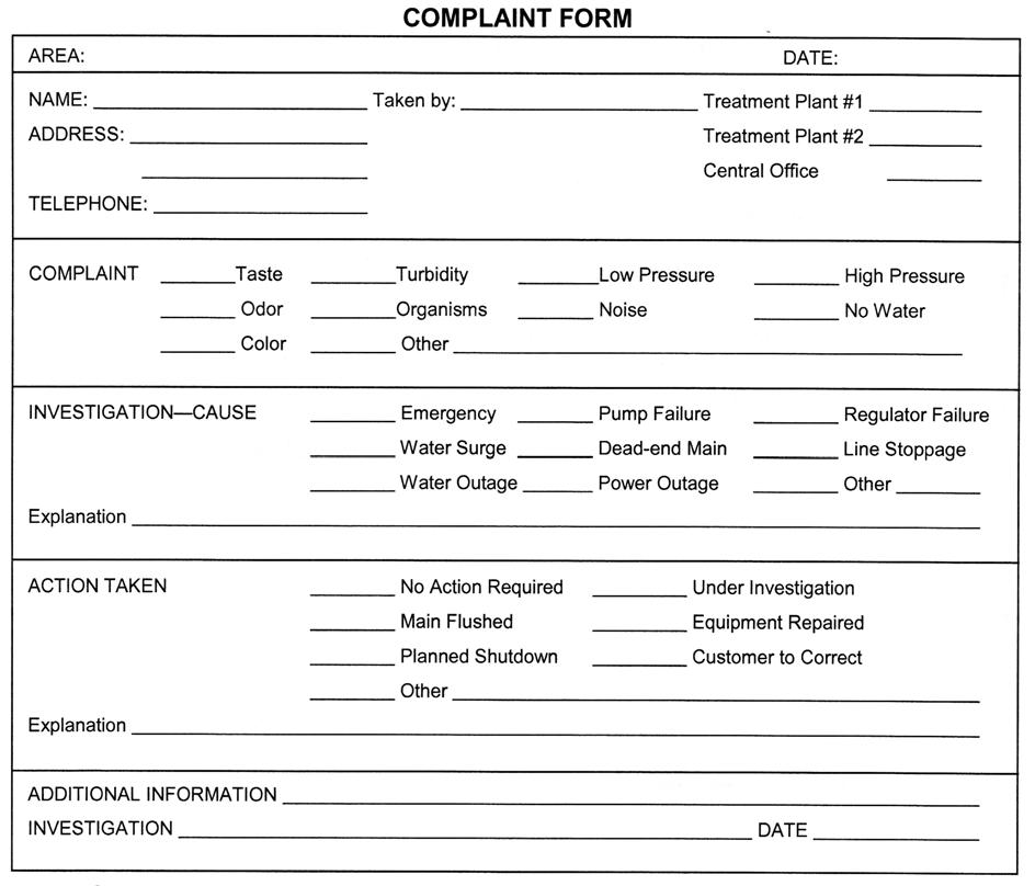
All complaints should be treated as legitimate and investigated as soon as possible. If the person with the complaint is loud and abusive, you should not reply in kind. Instead, show concern, listen carefully and calmly, and offer to look into the complaint.
Assure you understand the problem, then make every effort to give the customer an answer in nontechnical language. If you don't know the answer, refer the customer to the proper person.
Follow up with a phone call, postcard, or an email to make sure everything is satisfactory.
A complaint form ensures each problem is investigated and resolved (Figure2.2).
Public Relations Maintaining a Good Public Image
PM 2 - 8
©2017, Texas A&M Engineering Extens ion Service. All rights reserved.
Figure 2.2: Complaint form. Source:TEEX.
Grounds and Facilities
The proper maintenance and appearance of pump stations, storage tanks, treatment plants, and grounds indicates to the public your professional attitude. If facilities are dirty, run-down, in need of painting, or overgrown with weeds, you will be unable to convince the public you are doing a good job!
If your utility has a poor image, the public may not support bond issues or rate increases. The public can even lose confidence in the quality of their water.
Water utility personnel must do their best to provide quality water and service to the customers who are paying for it.
Public Relations Summary and Review
•Perform preventive maintenance so that service does not go out of order.
•Accept routine requests with enthusiasm, as though they are as important to the utility as they are to the customer.
•Listen willingly to special requests and seek solutions to oblige the customer within utility policy.
•Listen sympathetically to complaints. If the utility is at fault, correct the problem in a timely manner. If the customer is mistaken, handle the situation tactfully.
•Schedule appointments for installation and repair at the convenience of the customer whenever possible.
•Treat customers as though another water utility across the street is competing for your customers.
•Be certain you understand what you are doing. Take pride in your work and appearance, be courteous, and show respect for others and their property.
Public Relations Maintaining a Good Public Image ©2017, Texas A&M Engineering Extens ion Service. All rights reserved. PM 2 - 9
Summary
Whatever you do is seen directly or indirectly by the public and it is your responsibility to be professional. You must strive to maintain a good image with the public. Public relations is something that is not very often thought of as a requirement for water utility operators, but you must exude good public relations constantly.
In this module, you have learned how the interactions of water utility personnel with the public can impact public relations. In addition, you have learned that a neat and professional appearance is equally important to creating a positive public relations experience.
Public Relations Summary ©2017, Texas A&M Engineering Extens ion Service. All rights reserved. PM 2 - 10
Module 2 Review Questions
1.Public relations (PR) is the relationship between YOU, the water utility employee, and the mayor.
a.true
b.false
2.The keys to good customer relations are (1) everything the utility does is PR, (2) customers are entitled to courteous treatment, (3) every employee is a PR person.
a.true
b.false
3.Meter readers are the persons with whom customers have the least contact.
a.true
b.false
4.Meter readers can be ambassadors of goodwill.
a.true
b.false
5.Maintenance crews can warn customers of service interruptions and provide signs and barriers to protect the public.
a.true
b.false
6.The plant operator is responsible for treating the water to assure it is safe to drink and use.
a.true
b.false
7.Water bills should be accurate, itemized, and neat, and payment should be optional.
a.true
b.false
8.It is not important that the utility have a sense of pride and professionalism.
a.true
b.false
Public Relations Module 2 Review Questions ©2017, Texas A&M Engineering Extens ion Service. All rights reserved. PM 2 - 11
9.All employees should be kept informed of utility plans and policies.
a.true
b.false
10.Complaints should be treated as “griping” and investigated as a last priority.
a.true
b.false
11.In small water systems the operator is often ________.
a.meter reader, repair crew, and pump operator
b.the highest paid employee
c.a college graduate
d.all listed
12.“Stuffers” sent to customers in billing statements may contain ________.
a.departments to call for service
b.explanations of utility policy
c.a history of the utility
d.tips on water conservation
e.all the above
13.Delinquent payment notices should be ________.
a.tactful and tasteful
b.mailed in an envelope
c.businesslike
d.all listed
14.EPA requires community water systems to provide customers with a ________ report on the system’s water quality.
a.weekly
b.monthly
c.yearly
d.none listed
Public Relations Module 2 Review Questions ©2017, Texas A&M Engineering Extens ion Service. All rights reserved. PM 2 - 12
15.If these reports are attractive and easy to ________, they can build goodwill and trust with the customer.
a.misinterpret
b.misconstrue
c.misunderstand
d.understand
16.Good treatment of employees includes fair wages, benefits, and ________ working conditions.
a.tense
b.safe
c.hazardous
d.insecure
17.Follow up with a phone call or ________ to make sure everything is satisfactory.
a.postcard
b.email
c.letter
d.a and b
18.Water plant facilities should be kept neat and clean to ________.
a.indicate your professional attitude
b.keep public support
c.keep confidence in the water quality
d.all listed
19.Listen to special requests and seek solutions to oblige the customer within ________.
a.utility policy
b.five working days
c.tradition
d.secrecy
Public Relations Module 2 Review Questions ©2017, Texas A&M Engineering Extens ion Service. All rights reserved. PM 2 - 13
20.Treat customers as though another water utility across the street is competing for your ________.
a.job
b.employees
c.customers
d.revenue
Public Relations Module 2 Review Questions ©2017, Texas A&M Engineering Extens ion Service. All rights reserved. PM 2 - 14
Water Quality
Terminal Objective
Upon the successful completion of this module, the participant will be able to describe the attributes of water from various sources.
Enabling Objectives
1.Explain the hydrologic cycle.
2.List the various uses of water.
3.Describe the preparation of water for public use.
4.Describe the physical characteristics, including the sources, of water.
5.Explain water quality standards.
©2017, Texas A&M Engineering Extens ion Service. All rights reserved.
Module
©2017, Texas A&M Engineering Extens ion Service. All rights reserved. PM 3 - 2
Water Quality
Three-fourths of the earth's surface is water, but only a small portion is available for the public water supply.
Of the earth's fresh water, about 75% is frozen in the polar ice caps. About 25% is under ground, where only a small portion can be tapped by wells. About 1/3 of 1% of fresh water occurs in lakes and rivers and about 20% of that is found in the Great Lakes.
Water is composed of two atoms of hydrogen and one atom of oxygen, represented by the molecular formula H2O.
Water may be found in the following three states:
•Solid (ice). Water freezes at a temperature of 32° Fahrenheit (0° Celsius).
•Liquid (water). One gallon of fresh water weighs 8.34 pounds.
•Water vapor (gas, steam). Water boils at 212° Fahrenheit (100° Celsius), generating steam.
The concept that water is life is supported in the following facts:
•The human body is approximately 70% water.
•Water makes up approximately 83% of the blood.
•Water helps digest food and transport body waste.
•Water lubricates our joints and regulates body temperature.
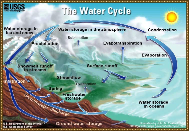
Hydrologic Cycle
Water on the earth has been here since the beginning of time and it moves in a cycle between the earth and the atmosphere. This recycling process is called the hydrologic cycle (Figure3.1).
Water vapor rises from oceans, rivers, lakes, and the ground into the air, a process called evaporation. Sublimation is the process where ice and snow evaporate into the atmosphere without first melting into a liquid form. Water vapor is released from plant life in a process called transpiration.
The water vapor is carried upward by rising currents of warm air to form clouds. When the vapor reaches cooler air high in the atmosphere, it condenses into rain, sleet, snow, or hail, which is called precipitation.
Water Quality Introduction ©2017, Texas A&M Engineering Extens ion Service. All rights reserved. PM 3 - 3
Introduction
Water Quality Uses of Water
Uses of Water
Water is Life
When precipitation reaches the earth, it soaks into the ground, which is called infiltration. The water is then available for plants. If the water continues to infiltrate farther and reaches the water table, recharging the groundwater supply in a process called percolation, it may run off into rivers and streams, then into lakes and oceans.
Pure water is never found in this natural cycle. Impurities in water are caused by materials that dissolve into it.
Next to the air we breathe, water is our most vital need! All living things require water. Humans can live longer without food than without water.
The human body is about 70% water. Water makes up 83% of the blood. Water helps digest food and transports body waste. Water lubricates our joints and regulates body temperature.
©2017, Texas A&M Engineering Extens ion Service. All rights reserved. PM 3 - 4
Figure 3.1: The hydrologic cycle. Source: USGS.
Domestic Use
Domestic use includes drinking, sanitation, and lawn watering. Contaminated water is most dangerous when utilized for drinking. Water quality standards, for all public water supplies, are based on the use of drinking.
Public Use
Public use includes recreation such as swimming, boating, and fishing. One of the most important purposes of a public water supply is fire protection. In Texas, to receive minimum recognition for firefighting capability under rate schedules adopted by the Texas Department of Insurance, a water system must be able to supply, at a fire’s location, at least 250 gallons per minute (gpm) for two hours during peak demand.
Business Use
Business use includes industrial, commercial, and agricultural purposes. Commercial customers may require higher water demands for air conditioning, sanitation, or product processes. Water for agricultural use usually does not come from a public supply, but is obtained near the site where it is used.
Throughout the United States, billions of gallons of water are treated and distributed to the customer daily for domestic purposes alone. In many communities, water and wastewater facilities are the largest investment. Yet, water costs only a few dollars per 1,000 gallons. Because this business is carried on quietly, economically, and dependably, most customers take little notice of it until service is interrupted.
Definitions
Average usage in a community depends on temperature, rainfall, water cost, amount of supply, and the economic level of the community. Customers in a hot, dry climate or wealthy neighborhoods tend to use more water.
System design engineers use a rule of thumb of 130 gallons per person per day when more accurate data is not available. The TCEQ (30 TAC Chapter 290.45) requires community water systems to have a minimum production capacity of 0.6 gpm per connection at peak demand. Increased production capacity is required if a normal operating pressure of 35 pounds per square inch (psi) cannot be maintained throughout the system, or if a minimum of 20 psi cannot be maintained during firefighting, line flushing, etc.
Water Quality Uses of Water ©2017, Texas A&M Engineering Extens ion Service. All rights reserved. PM 3 - 5
Maximum usage is the amount of water used at peak demand or during drought. This amount is important in planning treatment plants, pumping equipment, storage, and distribution systems.
Minimum usage usually occurs during winter months or periods of heavy rainfall. Minimum usage must be considered when establishing water rates and selecting pumping equipment.
Water Supply Production
Water for public use comes from one of two sources: groundwater or surface water. Groundwater is located beneath the earth's surface in water-bearing formations and is tapped by wells. Surface water is found in rivers, lakes, and reservoirs. Both of these natural sources of water are becoming scarce according to the TCEQ and other agencies. Therefore, treated salt water or wastewater is sometimes used for public supply.
Treatment
Prior to treatment, water is called raw water. The quality of water varies greatly. In order for a public water supply to be safe, clear, good tasting, odorless, noncorrosive, and reasonably soft, it must be treated.
Matter found in water may be organic or inorganic. The word “organic” comes from the word “organism.” Before scientists understood how to produce carbon compounds, only organisms (plants, animals, and humans) could produce them. At that time, organic matter was only living or once-living organisms, or matter produced by organisms. Sugar, paper, and leather are examples of organic matter produced by organisms.
Today, organic matter is defined as any compound that is primarily carbon based and contains hydrogen. Organic matter can be natural, such as sugar, or synthetic, such as plastic. Inorganic matter is not primarily carbon based, but may contain hydrogen. Sand, rock, metals, and minerals are examples of inorganic materials.
One of the purposes of water treatment is to reduce or neutralize harmful levels of organic and inorganic matter.
The most important treatment of water is disinfection, which destroys disease-causing microorganisms.
Water must be treated for turbidity—suspended particles in the water. Other treatment processes are used to remove taste, odors, and color.
Water Quality Water Supply ©2017, Texas A&M Engineering Extens ion Service. All rights reserved. PM 3 - 6
Water that is corrosive, scale producing, or staining must be treated. A public water supply must deliver potable water to its customers. Potable means the water is free of disease-causing organisms, has a chlorine residual, and is safe for human consumption.
Storage
Storage of water in a public water supply serves several purposes, which will be discussed in greater detail in module 7. Different types of storage facilities may be required: ground, elevated, and/or standpipe. The water utility employee is required to inspect and maintain these storage facilities.
Distribution
Distribution involves transporting water from its source through a treatment system, into storage, and finally to the customer. The water utility employee is involved in all stages of this process. Distribution will be discussed in greater detail in module 7.
State Requirements
In Texas the water utility operator is required to notify the TCEQ about changes to a public water system including the following:
•Changes in water source
•Changes in water quality
•Health hazards
•Before starting construction, the water utility must submit engineering plans to the TCEQ for approval.
Records
Recordkeeping should be a high priority for the water utility operator. Records can aid the operator in many ways. For example, they can assist in:
•planning future construction,
•keeping material and equipment on hand,
•determining work hours for each job, and
•budgeting.
The operator must keep records of water usage, system pressure, sample results, chlorine use, repairs, and maintenance.
Water Quality Water Supply ©2017, Texas A&M Engineering Extens ion Service. All rights reserved. PM 3 - 7
Texas public water systems (PWS) are required (30 TAC Chapter 290) to compile a monthly report indicating the amount of chemicals used, daily pumpage, dates of dead-end flushing, cleaning of storage tanks, and results of microbiological and chemical tests. Surface water systems also report raw and treated water analyses and daily turbidity analyses.
Water systems shall submit routine reports and any additional documentation that the executive director may require to determine compliance with the requirements of the rules. The reports must be submitted to the Texas Commission on Environmental Quality, Water Supply Division, by the tenth day of the month following the end of the reporting period. The reports must contain all the information required by the drinking water standards and the results of any special monitoring tests that have been required. The reports must be completed in ink, typed, or computer-printed, and must be signed by the licensed operator having the responsibility for the day-to-day operation of the system (generally/usually the chief operator) (Figure3.2, Figure3.3, and Figure3.4).
Water Quality Water Supply ©2017, Texas A&M Engineering Extens ion Service. All rights reserved. PM 3 - 8
Reports
MONTHLY OPERATING REPORT
Any additional information you wish to provide:
I certify that I am familiar with the information contained in this report and that, to the best of my knowledge, the information is true, complete, and accurate.
Water Quality Water Supply
PM 3 - 9
©2017, Texas A&M Engineering Extens ion Service. All rights reserved.
PUBLIC WATER SYSTEM NAME: PWS ID No.: Report for Number of Active Service the Month of: Connections this Month: 1 2 3 4 5 6 7 8 9 10 11 12 13 14 15 16 17 18 19 20 21 22 23 24 25 26 27 28 29 30 31 Total Avg Max Min
Figure 3.2: Monthly Operating Report (TCEQ-0811). Source:TCEQ.
Operator's Signature: Date: Certificate No. and Class: TCEQ - 0811 (DRAFT 7-4-06) GW-PWMOR
FOR PUBLIC WATER SYSTEMS THAT ARE USING GROUNDWATER SOURCES OR ARE PURCHASING TREATED WATER FROM ANOTHER PUBLIC WATER SYSTEM From Wells Directly to Distr. Total Daily Production Pumpage to storage and distribution X 1000 Gals WATER PRODUCTION From Wells to Storage Tanks Purchased Water Directly to Distr. Purchased Water into Storage From SWTP or GWUDI Plant Date
Water Quality Water Supply
©2017, Texas A&M Engineering Extens ion Service. All rights reserved.


PM 3 - 10
SURFACE WATER MONTHLY OPERATING REPORT FOR PUBLIC WATER SYSTEMS THAT ARE USING SURFACE WATER SOURCES OR GROUND WATER SOURCES UNDER THE INFLUENCE OF SURFACE WATER Summary Page PUBLIC WATER PLANT NAME SYSTEM NAME: OR NUMBER: I certify that I am familiar with the information contained in this report and that, PWS ID No.: to the best of my knowledge, the information is true, complete, and accurate. Plant ID No.: Operator's Signature: Report for the Month of: Certificate No. & Grade: Date: TREATMENT PLANT PERFORMANCE Total number of turbidity readings: Number of 4-hour periods when plant was off-line: Number of readings above 0.10 NTU: Number of 4-hour periods when plant was on-line Number of readings above 0.3 NTU: but turbidity data was not collected: Number of readings above 0.5 NTU: Number of days when plant was on-line Number of readings above 1.0 NTU: but individual filter turbidity data was not collected: Maximum allowable turbidity level: 0.3 Number of days with readings above 1.0 NTU: (2) Percentage of readings above this limit: % (1) Number of days with readings above 5.0 NTU: (3) Statistical Maximum turbidity reading: NTU Average turbidity value: NTU Summary Minimum turbidity reading: NTU Standard deviation: NTU CFE 95th percentile value: NTU IFE 95th percentile: NTU Number of days with a low CT Average log inactivation for Giardia: for no more than 4.0 consecutive hours: Average log inactivation for viruses: Number of days with a low CT Number of days when profiling data was not collected: for more than 4.0 consecutive hours: (4) Number of days when CT data was not collected: Minimum disinfectant residual required leaving the plant: mg/L, measured as Total Chlorine Number of days with a low residual for no more than 4.0 consecutive hours: Number of days with a low residual Number of days when disinfectant residual for more than 4.0 consecutive hours: (5) leaving the plant was not properly monitored: DISTRIBUTION SYSTEM Minimum disinfectant residual required in distribution system: mg/L, measured as Total Chlorine Total number of readings this month: Average disinfectant residual value: Percentage of readings with a low residual this month: % (6A) Number of readings with a low residual: Number of readings with no detectable residual: Percentage of readings with a low residual last month: % (6B) ADDITIONAL REPORTS & WORKSHEETS SURFACE WATER MONTHLY OPERATING REPORT TEXAS COMMISSION ON ENVIRONMENTAL QUALITY WATER SUPPLY DIVISION/PUBLIC DRINKING WATER SECTION (MC-155) P.O. BOX 13087, AUSTIN, TEXAS 78711-3087 TCEQ - 0102C-MGD (Rev. 02-15-16) PAGE 1 SWMOR 0.5 No additional IFE Reports are required this month. Additional report(s) for individual filter monitoring required: 0.5 Additional report(s) for individual filter monitoring submitted: NONE Filter Assessment CPE Filter Profile CPE (11) CPE (11 Filter Profile (9) ilter Filter Assessment (10) ONE NONE Fi NO
Figure 3.3: Surface Water Monthly Operating Report—Page 1. Source:TCEQ.
VIOLATION TYPE
SURFACE WATER MONTHLY OPERATING REPORT FOR PUBLIC WATER SYSTEMS THAT ARE USING SURFACE WATER SOURCES OR GROUND WATER SOURCES UNDER THE INFLUENCE OF SURFACE WATER (cont.)
PUBLIC NOTICES
VIOLATION OCCURRED?
TREATMENT TECHNIQUE
Were more than 5.0% of the turbidity readings above the acceptable level?see (1) on the Summary Page
Were there any days with turbidity readings above 1.0 NTU?see (2) on the Summary Page
Were there any days with turbidity readings above 5.0 NTU?see (3) on the Summary Page
Were there any periods when the plant failed to meet the CT requirements for more than 4.0 consecutive hours?see (4) on the Summary Page
Were there any periods when the residuals leaving the plant fell below the acceptable level for more than 4.0 consecutive hours?see (5) on the Summary Page
Were more than 5.0% of the residuals in the distribution system below the acceptable level for two months in a row?see (6A) and (6B) on the Summary Page
Were there any days when the plant failed to report all of the required Combined Filter Effluent (CFE) turbidity readings?see the Turbidity Data Page
Were there any days when the plant failed to report all the CT data needed to evaluate the level of microbial inactivation achieved?see the Disinfection Data Page
Were there any days when the plant failed to report the minimum disinfectant residual entering the distribution system?see the Turbidity Data Page
Did the system fail to collect enough samples in the distribution system to meet the minimum disinfectant monitoring requirements?see (8) on the Summary Page
MONITORING & REPORTING
Were there any days when the plant failed to report the maximum individual filter effluent (IFE) turbidity level produced by each filter?see the Filter Data Page
Were there any days when the plant failed to report the IFE turbidity level 4-hours after beginning a filter run?see the Filter Data Page
Did the plant fail to submit a Filter Profile Report if one was required?see (9) on the Summary page
Did the plant fail to submit a Filter Assessment Report if one was required?see (10) on the Summary Page
Did the plant fail to submit a Comprehensive Performance Evaluation Request if one was required?see (11) on the Summary Page
Did the plant fail to collect at least one Total Organic Carbon sample set? - see TOCMOR Page
Treatment technique violation notices are due no later than the end of the next business day. Please include a copy if possible.
* Copies of each Public Notice must accompany this report if they have already been issued. Certificate No.
SUMITTED BY: and Grade: Date:
TCEQ - 0102C-MGD (Rev. 02-15-16) PAGE 1 - Addendum SWMOR
©2017, Texas A&M Engineering Extens ion Service. All rights reserved.
Water Quality Water Supply
PM 3 - 11
Figure 3.3: Surface Water Monthly Operating Report. (continued)
Page Addendum (Violations
Public Notices) PUBLIC WATER PLANT NAME SYSTEM NAME: OR NUMBER: PWS ID No.: Month: Year: PENDING
Summary
and
VIOLATION DATES DATE OF NOTICE DESCRIPTION OF VIOLATION DATE OF NOTICE
NOTICE TO TCEQ NOTICE TO CUSTOMER *
DISINFECTANT LEVEL QUARTERLY OPERATING REPORT (DLQOR) FOR GROUNDWATER OR PURCHASED-WATER PUBLIC WATER SYSTEMS-ANY SIZE
PWS Name: PWS ID:
Type of Disinfectant Used in Distribution System*:
*If you used chloramines and free chlorine at any time during this quarter, select both.
First Month of Quarter: Monthly Summary
Month: Was the PWS active this month?
Average of all disinfectant residuals for this month
Second Month of Quarter: Monthly Summary
Month: Was the PWS active this month?
Average of all disinfectant residuals for this month
of residuals collected this month for this month for this month
Third Month of Quarter: Monthly Summary
Month: Was the PWS active this month? Average of all disinfectant residuals for this month
Quarterly Summary and Certification
(For your own records)
TCEQ-20067 (Revised 03/29/2011)
Step 2:
data for a different system.
Complete this form for the previous quarter at the beginning of April, July, October, and January; and submit in time for it to be received by the TCEQ by the 10th of the month. Always print and sign form, and keep a copy with your records for TCEQ review. Step 1: Sign and Mail to: TCEQ / PDW MC-155 Attn: DLQOR PO Box 13087 Austin, TX 78711-3087
©2017, Texas A&M Engineering Extens ion Service. All rights reserved. PM 3 - 12
Water Quality Water Supply
Figure 3.4: Disinfectant Level Quarterly Operating. Source:TCEQ.
DLQOR
Number
Number below MIN
Number with NO residual
of residuals collected this month
for this month
for this month
Number
Number
of residuals collected this month for this month for this month
Lowest residual
Highest residual
Average of all disinfectant residuals for this quarter
for this quarter
for this quarter
Name: Today's Date: Title: License #:
Select Quarter: Select Year: YES NO YES NO YES NO mg/L mg/L mg/L mg/Lmg/Lmg/L Enter Name Signature Email address: Number below MIN Number below MIN Number with NO residual Number with NO residual
% % % % % % readings readings readings Phone Number: readings readings readings readings readings readings Click the button below to start over or to reset to enter
I certify that I am familiar with the information contained in this report and that, to the best of my knowledge, the information is true, complete, and accurate. 4/1/11 Clear Form
Print Copy Print to Mail
Water Characteristics
Water is never found pure in nature. When water falls as rain, impurities are picked up from the air. As the water passes over or through the earth's surface, other impurities are dissolved or suspended. Impurities give water characteristics that concern operators.
Physical Characteristics
Learning Check
1.What is a physical characteristic?
The physical characteristics of water include temperature, turbidity, color, taste, and odor.
Temperature
Compared to the seasonal and day-to-night temperature changes of surface water, the temperature of groundwater is constant. Shallow groundwater, approximately 60 feet or less, may change several degrees with the seasons. It averages 2°F–3°F warmer than the average annual air temperature. Below 60 feet, groundwater temperature increases about 8°F for every 500 feet of depth. However, there are exceptions. Dialville in central east Texas has well water of 120°F from 3,000 feet. Falls City, approximately 30 miles southeast of San Antonio, has well water of 130°F–150°F from 3,800 feet. Water in lakes and reservoirs tends to stratify in layers of different temperature. Temperature affects water quality, thus it is important to draw water from temperature levels with the best quality.
Turbidity
Turbidity is the amount of suspended matter, such as clay, silt, organic matter, and microorganisms, in water. Turbidity gives water a murky or turbid look. While most groundwater is relatively free of suspended matter, turbidity can be a major problem in surface water. A system's filtered water must be 0.3 Nephelometric Turbidity Units (NTU) or less in at least 95% of the measurements taken each month, and no sample can exceed one NTU.
Water Quality Water Characteristics ©2017, Texas A&M Engineering Extens ion Service. All rights reserved. PM 3 - 13
Color
Color in water can result from mineral or organic matter. True color is dissolved in water (in solution) and cannot be removed by filtering. Tea in water is an example of true color. Other color, such as the red water caused by oxidized iron, is in suspension and can be filtered out. Suspended color is called apparent color. Color above 15 units is objectionable in a public water supply.
Color is measured by comparison of the sample to known concentrations of colored solutions or against colored glass disks. A color unit is produced by 1 mg/L platinum. Twenty units is almost undetectable and 300 units is the color of weak tea.
Iron and manganese exist in both the dissolved and suspended states. As long as they are dissolved, no staining or color problems occur. When the iron or manganese come out of solution into the suspended state, color and staining occur. When these constituents are in sufficient concentrations to cause problems, removal may be required. Aeration or chlorination at the proper pH will oxidize the iron or manganese, causing precipitates to form. These precipitates can then be removed by settling or filtration.
Taste and Odor
Taste and odors in water result from algae, bacteria, decaying organic matter, gases, and chemicals such as manganese, zinc, copper, iron, magnesium, sodium, and potassium.
A scale called the Threshold Odor Number (TON) measures odor. The scale relates to the number of dilutions required before the sample is odorless. Odor greater than a scale of three is undesirable.
Taste and odor may be controlled by aeration or by using chlorine, chlorine dioxide, activated carbon, potassium permanganate, or lake destratification. Destratification provides dissolved oxygen content at all reservoir levels, uniform temperatures, and a thorough mixing of the strata involved.
Iron and manganese exist in both the dissolved and suspended states. As long as they are dissolved, no staining or color problems occur. When the iron or manganese come out of solution, into the suspended state, color and staining occur. When these constituents are in sufficient concentrations to cause problems, removal may be required. Aeration or chlorination at the proper pH will oxidize the iron or manganese, causing precipitates to form. These precipitates can then be removed by settling or filtration.
Water Quality Water Characteristics ©2017, Texas A&M Engineering Extens ion Service. All rights reserved. PM 3 - 14
Chemical Characteristics
Chemical characteristics include hardness, pH, solids, and gases. Sight, smell, or taste generally cannot detect the presence of dissolved chemicals. Chemical impurities are determined by laboratory analysis. Samples must be taken on treated water as furnished to the customer.
For chemical analysis, surface supplies are sampled once a year and groundwater is normally sampled every three years.
Chemicals in water are expressed in milligrams per liter (mg/L). In water, which weighs 8.34 lbs/gal, 1 mg/L is equal to one part per million (ppm) by weight.
Hardness
Calcium and magnesium and other minerals cause hardness in water. Hard water makes soap difficult to lather and scale forms on plumbing. Hardness is more of a problem in groundwater than surface water. Water is considered hard when it exceeds 100 mg/L of calcium carbonate.
Learning Check
1.What is the level of hardness in your water?
pH
pH is a measure of the hydrogen ion concentration in water, or how acidic or basic a solution is. The pH scale ranges from 0 to 14. From 0 to <7 is acidic and from >7 to 14 is basic or alkaline. A pH of 7 is neutral. If water has a pH of 6.5, it is slightly acidic. If the pH is 7.8, the water is slightly basic. A pH of 8.5 is more basic than a pH of 7.8.
Sulfuric, hydrochloric, and nitric acids will lower the pH below 7. Alkalis such as caustic, lime, or soda ash will raise the pH above 7.
pH is important in coagulation, corrosion control, prevention of scale, and chlorination. Red water caused by oxidized iron is influenced by pH.
Solids
One analysis of chemical water quality is the quantity of solids:
•Suspended solids can be removed by filtration.
•Dissolved solids cannot be removed by filtration. Total dissolved solids should not exceed 1,000 mg/L.
Water Quality Water Characteristics ©2017, Texas A&M Engineering Extens ion Service. All rights reserved. PM 3 - 15
Water Quality
Water Quality Standards
•Total solids are the sum of dissolved and suspended solids. High concentrations of solids cause scale in equipment and taste in drinking water.
Gases
Common gases found in water include hydrogen sulfide (which has a rotten egg odor), carbon dioxide, and methane. Gases come from mineral deposits or are given off by decaying organic matter.
Hydrogen sulfide is heavier than air, colorless, flammable, and toxic. Carbon dioxide is heavier than air, odorless, colorless, does not burn, and is suffocating. Methane is lighter than air, odorless, colorless, and explosive.
Water Quality Standards
Standards
Safe Drinking Water Act—PL-93-523
Maximum Contaminant Levels (MCL)
As prescribed by the United States Environmental Protection Agency
Maximum Inorganic Chemical Contaminant Levels
Maximum Contaminant Levels (MCL) are outlined in the Safe Drinking Water Act. Table3.1 provides the maximum contaminant levels for inorganic chemicals as described in the Safe Drinking Water Act PL-93-523.
©2017, Texas A&M Engineering Extens ion Service. All rights reserved. PM 3 - 16
Table 3.1: Inorganic Chemicals—Maximum Contamination Levels
Arsenic, mercury, and thallium are highly toxic metals.
Nitrate. At the discretion of the state, nitrate levels not to exceed 20mg/L (as nitrogen) may be allowed in a non-community system if the supplier of water demonstrates to the satisfaction of the state that such water will not be available to children under six months of age.
Excess nitrogen causes “blue baby” syndrome (methemoglobinemia), a disease that prevents red blood cells from carrying oxygen, and resulting in suffocation and blue skin color. Baby formula made with water high in nitrogen compounds is the danger. Children older than six months and adults are not at risk.
The major source of nitrogen is fertilizer and animal waste from dairies, hog farms, and feedlots. Rainwater runoff carries nitrogen compounds into drinking water sources such as lakes and rivers, or the runoff percolates into aquifers.
Water Quality Water Quality Standards ©2017, Texas A&M Engineering Extens ion Service. All rights reserved. PM 3 - 17
Contaminant mg/L Applicable System Antimony0.006CN Arsenic 0.010 CN Asbestos 7 million fibers/liter (longer than 10 µm) CN Barium 2 CN Beryllium0.004CN Cadmium 0.005 CN Chromium0.1CN Cyanide 0.2 (as free Cyanide) CN Fluoride4C Mercury 0.002 CN Nitrate10 (as nitrogen)CNT Nitrite 1 (as nitrogen) CNT Nitrate & Nitrite10 (as nitrogen)CNT Selenium (Total) 0.05 CN Thallium0.002CN C = Community N = Non-transient, non-community T = Transient, non-community
The standards are expressed as mg/L of nitrate nitrogen content. 10mg/L of nitrate nitrogen equals 44 mg/L of nitrate compound.
Fluoride. The EPA primary MCL for fluoride is 4.0 mg/L; and at this level, it will causes mottling of teeth, a condition known as fluorosis. The tooth enamel is eaten away by the high fluoride concentrations. The State of Texas secondary standard for fluoride is 2.0 mg/L. Concentrations higher than this may cause staining of the teeth. People routinely drinking water with fluoride levels between 2.0 and 4.0 mg/L will have brown teeth. In low concentrations, fluoride has been shown to reduce dental cavities. Water systems that have chosen to add fluoride maintain a maximum concentration of 0.7 mg/L.
Maximum Organic Chemical Contaminant Levels
Table3.2 defines the maximum contaminant levels for a partial list of man-made organic chemicals, including pesticides and herbicides, in community water systems.
Table 3.2: Organic Chemicals—Maximum Contamination Levels
Water Quality Water Quality Standards ©2017, Texas A&M Engineering Extens ion Service. All rights reserved. PM 3 - 18
Contaminant mg/L Constituent mg/L Alachlor0.002Ethylbenzene Dibromide (EDB)0.00005 Atrazine 0.003 Heptachlor 0.0004 Benzene0.005Heptachlor or Epoxide0.0002 Carbofuran 0.04 Lindane 0.0002 Carbon Tetrachloride0.005Methoxychlor0.04 Chlordane 0.002 Pentachlorophenol 0.001 2,4-D0.07Polychlorinated Biphenyls (PCB)0.005 Dibromochloropropane (DBCP) 0.0002 Styrene 0.1 o-Dichlorobenzene0.6Tetrachloroethylene0.005 p-Dichlorobenzene 0.075 Toluene 1 1,2-Dichloroethane0.005Toxaphene0.003 1,1-Dichloroethylene 0.007 2,4,5-TP (Silvex) 0.05 cis-1,2-Dichloroethylene0.071,1,1-Trichloroethane0.2 trans-1,2-Dichloroethylene 0.1 Trichloroethylene 0.005 1,2-Dichloropropane0.005Vinyl Chloride0.002 Endrin 0.002 Xylenes (total) 10 Ethylbenzene0.7
Turbidity
This standard applies to systems that treat surface water and to any groundwater under the influence of surface water (e.g. shallow wells).
A system's combined filter effluent must be less than or equal to 0.3 NTU in at least 95% of the measurements taken each month and no sample can exceed one NTU.
Trihalomethanes (THM) and Haloacetic Acids (HAA)
Preventing THM and HAA Formation
Trihalomethanes (THM) and Haloacetic Acids (HAA) are byproducts of drinking water chlorination. These byproducts form when chlorine reacts with dissolved natural organic matter, mostly plant life. These byproducts may cause problems with the liver, kidneys, or central nervous systems, and may increase cancer risk. Also, THMs have possible reproductive health risks.
Surface water usually contains natural organics and groundwater usually does not. Therefore, most surface water treatment plants are required to combine chlorine with ammonia (chloramine) before disinfecting the treated water. Combining chlorine with ammonia greatly reduces THM and HAA formation. Systems using groundwater that does not contain natural organics (most do not) are allowed to use uncombined chlorine, called free chlorine.
THMs and HAAs MCLs
The MCL for total trihalomethanes is 0.08 mg/L and the MCL for HAA5 is 0.06 mg/L. These MCLs apply to all community and non-transient, non-community water systems using surface water or groundwater under the direct influence of surface water, and groundwater systems serving at least 10,000 persons.
Public Notification Requirements
A public water system failing to comply with an MCL or treatment technique that poses an acute risk to public health shall notify persons served by the system within 45 days after the violation as follows:
1.Publication in a daily newspaper serving the system. If none exists, the notice shall be issued by hand delivery or by posting in conspicuous places within the area served.
2.Furnish a copy of the notice to radio and television stations serving the area.
Water Quality Water Quality Standards ©2017, Texas A&M Engineering Extens ion Service. All rights reserved. PM 3 - 19
The system telephone number must be included and be multilingual, if necessary. Other rules may apply.
Secondary Contaminant Levels
Table3.3 shows the levels of secondary contamination as adopted by the State of Texas.
The Lead and Copper Rule
To reduce lead and copper in public drinking water, EPA adopted the Lead and Copper Rule in 1991. The rule applies to community and non-transient, non-community water systems.
Water Quality Water Quality Standards ©2017, Texas A&M Engineering Extens ion Service. All rights reserved. PM 3 - 20
Contaminant Level Aluminum0.05 to 0.2 mg/L2 Chloride 300 mg/L Color15 color units Copper 1.0 mg/L Corrosivitynon-corrosive Foaming Agents 0.5 mg/L Fluoride2.0 mg/L Hydrogen Sulfide 0.05 mg/L Iron0.3 mg/L Manganese 0.05 mg.L Odor3 threshold odor number pH >7.0 Silver0.10 mg/L3 Sulfate 300 mg/L Total Dissolved Solids (TDS)1000 mg/L Zinc 5 mg/L
limits cannot be exceeded without written permission from the TCEQ.
Table 3.3: Secondary Contaminant Levels as Adopted by the State
These
Corrosive water leaches lead and copper from plumbing fixtures and service lines. Copper is an essential nutrient, but in excess amounts can cause gastrointestinal distress or liver or kidney damage. Lead can impair physical or mental development in children and cause kidney problems or high blood pressure in adults.
Instead of setting MCLs, EPA set Maximum Contaminant Level Goals (MCLG) at zero for lead and 1.3 mg/L for copper. MCLGs are non-enforceable, optimal health-based targets. However, the Lead and Copper Rule requires Action Steps.
If sampling indicates lead exceeds 0.015 mg/L or copper exceeds 1.3mg/L (action levels) in 10% or more samples, the water system must take prescribed action. Prescribed actions include source water treatment, corrosion control, public education, and possible replacement of lead service lines.
Sampling Requirements
Samples for lead and copper are to be taken at high-risk locations such as homes with lead solder installed after 1982, homes with lead pipes, and homes with lead service lines.
Water in the pipe must not flow for six hours (but no longer than 18 hours) before sample collection. Then a one-liter, first-draw sample is taken from the cold water kitchen or bathroom tap. The samples must not be drawn from the hot water tap because lead dissolves more easily into hot water. Utility personnel or trained residents may take samples, and utility personnel will take the samples to an approved lab.
Water systems that meet the action levels or maintain corrosion control for two consecutive six-month periods may reduce sampling to once per year. Water systems meeting requirements for three consecutive years may reduce sampling to once every three years (Table3.4).
*Systems greater than 100,000 population are required 100 initial sites and 50 reduced sites.
Water Quality Water Quality Standards ©2017, Texas A&M Engineering Extens ion Service. All rights reserved. PM 3 - 21
System Population Size No. of Sampling Sites (Initial Sampling) No. of Sampling Sites (Reduced Monitoring) 10,000 to 100,000*6030 3,301 to 10,000 40 20 501 to 3,3002010 101 to 500 10 5 > 10155
Table 3.4: Sampling Requirements for Lead and Copper
Prescribed Action
If 10% or more samples exceed the action levels of 0.015 mg/L for lead or 1.3 mg/L for copper, the water systems must take prescribed actions, such as sampling the water source for lead or copper.
If treatment is required, the state may specify a treatment such as the following:
•Ion Exchange: This is accomplished by exchanging calcium Ca2+ and magnesium Mg2+ cations against sodium Na+ or hydrogen H+ cations.
•Reverse Osmosis: In simple terms, reverse osmosis is the process of pushing a solution through a filter that traps the solute on one side and allows the pure solvent to be obtained from the other side.
•Lime Softening: In lime softening, hydrated lime (calcium hydroxide, Ca(OH)2) is added to water to precipitate calcium carbonate before the water is used. The amount of lime required will depend on hardness levels. The process requires a settlement period and its effectiveness is governed by the pH of the water.
•Coagulation and Filtration: This process is surface water treatment, which is detailed in module 5.
If the water source does not contain lead or copper, the system must submit to the state a plan for corrosion control such as pH and alkalinity adjustment, or addition of phosphate or silica corrosion inhibitors.
Water systems that maintain parameters with corrosion control over two consecutive six-month periods may reduce sampling during each six-month period. If parameters are maintained for three consecutive years, sampling may be reduced to once per year.
Public Notification
All public water systems exceeding the lead action level must deliver an EPA public education program to their customers within 60 days. This program informs the public of lead and copper health hazards and ways to minimize exposure in drinking water. Additionally, the system must deliver:
•bill stuffers to consumers and brochures to community institutions frequented by women and children;
•public education material to daily newspapers serving the community (every 12 months); and
•public service announcements to community television and radio stations (every six months).
Water Quality Water Quality Standards ©2017, Texas A&M Engineering Extens ion Service. All rights reserved. PM 3 - 22
After treatment, water systems that exceed action levels must replace lead or copper service lines under utility ownership. The utility must offer to replace customer portions of the service line at owner’s expense. The utility is not responsible for private plumbing inside homes.
A system must replace 7% of the service lines each year or demonstrate that the lines not replaced contribute less than the action levels. The system has 15 years to replace the dangerous service lines.
Reducing Lead Exposure
Early in 2011, President Obama signed into law the Reduction of Lead in Drinking Water Act, a measure that defines “lead-free” as not containing more than 0.2% lead when used with respect to solder and flux and not more than a weighted average of 0.25% lead when used with wet surfaces of pipes and pipe and plumbing fittings and fixtures. It also establishes a formula to calculate the weighted average of lead content in a pipe or plumbing fitting or fixture. These new limits went into effect January 4, 2014.
Summary
The diversity and dissection of water and its sources is complex. Regulatory agencies and their requirements are vital to our industry in the protection of general public water supplies. In the next module we will investigate groundwater.
In this module, you have learned about the hydrologic cycle and the physical and chemical characteristics of water. In addition, you should be able to describe the various uses of water, including domestic, public, and business. After reading this module, you should also be able to describe water quality standards and the various processes for preparing water for public use. Now that you have been given an overview of the water supply process from the hydrologic cycle to production, we will narrow our focus to the extraction, treatment, and distribution of groundwater.
Water Quality Summary ©2017, Texas A&M Engineering Extens ion Service. All rights reserved. PM 3 - 23
©2017, Texas A&M Engineering Extens ion Service. All rights reserved. PM 3 - 24
Water Quality Summary
Module 3 Review Questions
1.The molecular formula for water is HO2 a.true
b.false
2.Water occurs in three forms: solid ice, liquid water, and water vapor. a.true
b.false
3.The hydrologic cycle is the natural exchange of water between the earth and the atmosphere. a.true b.false
4.Average water use depends on temperature, rainfall, cost, supply, and economic level. a.true b.false
5.Groundwater is located above the earth’s surface and tapped by wells. a.true b.false
6.Surface water comes from rivers, lakes, and reservoirs.
a.true
b.false
7.Future water supplies will become more plentiful according to the TCEQ.
a.true
b.false
8.Surface water or groundwater prior to treatment is called fresh water.
a.true
b.false
Water Quality Module 3 Review Questions ©2017, Texas A&M Engineering Extens ion Service. All rights reserved. PM 3 - 25
9.Potable water means the water is free of disease-causing organisms, has a chlorine residual, and is safe for human consumption.
a.true
b.false
10.The state must be notified about changes to public water systems involving water source, water quality, and health hazards.
a.true
b.false
11.Before starting construction, the utility must submit engineering plans to the AWWA.
a.true
b.false
12.Operators must keep records of water usage, system pressure, sample results, chlorine use, repairs, and maintenance.
a.true
b.false
13.Surface water systems must mail reports to the TCEQ in Austin by the 5th of the following month.
a.true
b.false
14.Water is always found pure in nature.
a.true
b.false
15.Physical characteristics of water are temperature, turbidity, color, taste, odor, and pH.
a.true
b.false
16.Turbidity is the amount of suspended matter such as clay, silt, organic matter, and microorganisms in the water.
a.true
b.false
Water Quality Module 3 Review Questions ©2017, Texas A&M Engineering Extens ion Service. All rights reserved. PM 3 - 26
17.Color in water can result from mineral or organic matter.
a.true
b.false
18.True color is dissolved in water (in solution) and can be removed by filtration.
a.true
b.false
19.Red water caused by oxidized iron is in suspension (apparent color) and cannot be removed by filtering.
a.true
b.false
20.Taste and odor comes from algae, bacteria, organic matter, gases, and chemicals.
a.true
b.false
21.Surface water supplies should be sampled for chemical analysis every year and groundwater supplies should be sampled three times a year.
a.true
b.false
22.Calcium and magnesium and other minerals cause hardness in water.
a.true
b.false
23.The pH scale ranges from 1 to 14.
a.true
b.false
24.A pH of 7 is neutral.
a.true
b.false
25.Suspended solids can be removed by filtering and dissolved solids cannot.
a.true
b.false
Water Quality Module 3 Review Questions ©2017, Texas A&M Engineering Extens ion Service. All rights reserved. PM 3 - 27
26.Common gases found in water include hydrogen sulfide, carbon dioxide, methane, and sodium chloride.
a.true
b.false
27.Chemically, water is made of ________.
a.one atom of water
b.one atom of hydrogen and one atom of oxygen
c.two atoms of hydrogen and one atom of oxygen
d.one atom of hydrogen and two atoms of oxygen
28.The hydrologic cycle is ________.
a.nature’s way of recycling water
b.equipment used to measure distances
c.the way water filters through the earth
d.the process by which water runs into rivers and lakes
29.The quality standard for public water supplies is based on the use of water for ________.
a.firefighting
b.drinking
c.bathing
d.swimming
30.One of the most important purposes of a public water supply is ________.
a.swimming
b.landscape watering
c.car washing
d.firefighting
31.Organic matter includes ________.
a.sand
b.plants, animals, and humans
c.minerals
d.all listed
Water Quality Module 3 Review Questions ©2017, Texas A&M Engineering Extens ion Service. All rights reserved. PM 3 - 28
32.The most important treatment process is ________, which destroys disease-causing organisms.
a.filtration
b.disinfection
c.softening
d.fluoridation
33.Public water systems are required to compile a monthly report showing ________.
a.rate increases
b.accidents
c.dates of dead-end flushing
d.disciplinary action
34.Most groundwater is relatively free of suspended matter, but ________ can be a major problem in surface water.
a.turbidity
b.gases
c.sand
d.hot water
35.Color in a public water supply should be ________.
a.at least 15 units
b.less than three units
c.less than 15 units
d.red
36.Chemical characteristics include hardness, pH, solids, and ________.
a.gases
b.taste
c.temperature
d.color
Water Quality Module 3 Review Questions ©2017, Texas A&M Engineering Extens ion Service. All rights reserved. PM 3 - 29
37.Water is considered hard when it exceeds ________ mg/L of calcium carbonate.
a.0.1
b.10
c.100
d.1,000
38.A gallon of water weighs 8.34 pounds and 1 mg/L equals one ________.
a.million grams
b.thousand grams
c.part per thousand
d.part per million
39.Hydrogen sulfide is heavier than air, colorless, flammable, toxic, and has a ________ odor.
a.sweet
b.rotten egg
c.rotten fish
d.fragrant
40.Excessive nitrates in drinking water can cause ________ syndrome in infants.
a.bad baby
b.blue body
c.bloody baby
d.blue baby
41.Excessive amounts of fluoride may cause ________ or staining of teeth.
a.mottling
b.molding
c.cracking
d.yellowing
Water Quality Module 3 Review Questions ©2017, Texas A&M Engineering Extens ion Service. All rights reserved. PM 3 - 30
42.Trihalomethanes and haloacetic acids are byproducts of chlorination and may increase ________ risk.
a.mottled teeth
b.red water
c.typhoid
d.cancer
43.The action level for copper is 1.3 mg/L and for lead it is ________ mg/L.
a.15
b.1.5
c.0.015
d.0.15
Water Quality Module 3 Review Questions ©2017, Texas A&M Engineering Extens ion Service. All rights reserved. PM 3 - 31
3 Review Questions ©2017, Texas A&M Engineering Extens ion Service. All rights reserved. PM 3 - 32
Water Quality Module
Groundwater Production
Terminal Objective
Upon the successful completion of this module, the participant will be able to describe how groundwater is made usable.
Enabling Objectives
1.Explain the relationship of aquifers to types of wells.
2.Explain common methods of groundwater treatment.
©2017, Texas A&M Engineering Extens ion Service. All rights reserved.
Module
Groundwater Production ©2017, Texas A&M Engineering Extens ion Service. All rights reserved. PM 4 - 2
Introduction
In this module, we will discuss sources of groundwater for our earth, as well as major sources in the state of Texas. The discussion will include groundwater withdrawal, sanitation, and treatment.
Sources of Groundwater
The source of about 60% of the water supply in Texas, according to the Texas Water Development Board (TWDB), is from underground supplies and it serves about 1/4 of the population (Figure4.1). The protection of the wells against bacterial and chemical contamination is a matter of great concern to operators. While well water is usually clear and sparkling, many conditions may endanger the water.
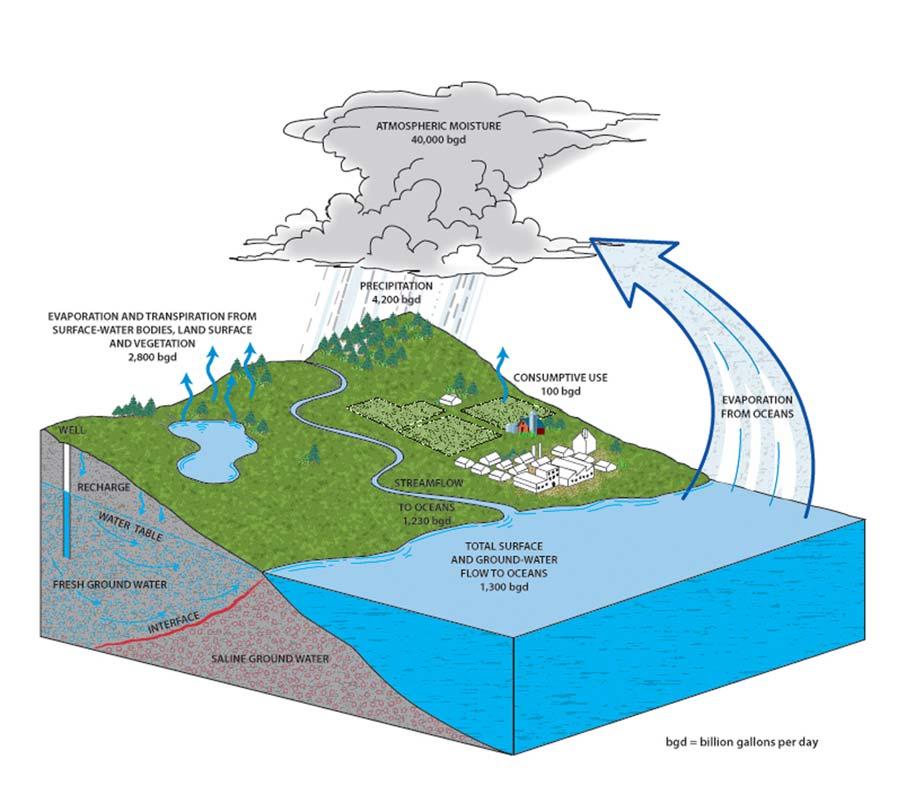
Groundwater Production Introduction ©2017, Texas A&M Engineering Extens ion Service. All rights reserved. PM 4 - 3
Figure 4.1: Sources of groundwater. Source: USGS.
Aquifers
Groundwater occurs below the earth's surface in water-bearing formations called aquifers. An aquifer must yield useful quantities of water to be used as a public water supply. These formations are found at different depths in different parts of the country (Figure4.2 and Figure4.3). Thus, it is much easier to locate and harvest groundwater in some areas than in others. Groundwater usually contains more dissolved minerals and gases than surface water, but fewer microorganisms.
Major Aquifers of Texas

County Boundaries
Pecos Valley Aquifer

Seymour Aquifer
Gulf Coast Aquifer
Carrizo - Wilcox Aquifer (Outcrop)
Carrizo - Wilcox Aquifer (Subcrop)
Hueco Mesilla Bolsons Aquifer
Ogallala Aquifer
Edwards - Trinity (Plateau) Aquifer (Outcrop)
Edwards - Trinity (Plateau) Aquifer (Subcrop) Edwards (Balcones Fault Zone) Aquifer (Outcrop)
(Balcones Fault Zone) Aquifer (Subcrop)
Aquifer (Outcrop)
Aquifer (Subcrop)
©2017,
PM 4 - 4
Groundwater Production Aquifers
Texas A&M Engineering Extens ion Service. All rights reserved.
GILLESPIE COMAL BANDERA GUADALUPE MEDINA WILSON ATASCOSA KARNES FRIO RED LAMAR BOWIE TITUS FRANKLIN HOPKINS MORRIS LEON ROBERTSON MADISON BRAZOS BURLESON WASHINGTON LEE BLANCO BASTROP FAYETTE CALDWELL LIVE OAK BEE MCMULLEN REFUGIO ARANSAS SAN PATRICIO DUVAL NUECES KLEBERG KENEDY BROOKS MILLS CORYELL SAN SABA LAMPASAS BELL MILAM GLASSCOCK GREEN REAGAN IRION CROCKETT SCHLEICHER MASON SUTTON KIMBLE SHELBY NACOGDOCHES SAN AUGUSTINE SABINE HOUSTON ANGELINA NEWTON JASPER POLK TYLER SAN JACINTO WOOD RAINS UPSHUR MARION VAN ZANDT HARRISON HENDERSON PANOLA CHEROKEE ANDERSON GONZALES LAVACA DEWITT VICTORIA GOLIAD WALKER AUSTIN COLORADO CHAMBERS FORT BEND WHARTON BRAZORIA HILL BOSQUE FREESTONE MCLENNAN LIMESTONE FALLS WILLACY CAMERON VERDE EDWARDS KINNEY UVALDE MAVERICK LASALLE WISE COLLIN TARRANT KAUFMAN HOOD JOHNSON ERATH NAVARRO HARDEMAN WILBARGER COTTLE FOARD WICHITA MONTAGUE ARCHER BAYLOR JACK YOUNG DAWSONBORDEN ANDREWSMARTINHOWARD WINKLER ECTOR MIDLAND LOVING WARD CRANE UPTON PECOS TERRELL DALLAM HARTLEY MOORE HEMPHILL OLDHAM CARSON SMITH RANDALLARMSTRONG DONLEY COLLINGSWORTH PARMERCASTROSWISHERBRISCOEHALLCHILDRESS EL PASO HUDSPETH CULBERSON JEFF PRESIDIO JEFFERSON HARDIN ORANGE BAILEYLAMBHALEFLOYD MOTLEY COCHRAN CROSBY DICKENSKING YOAKUM WEBB JIM HOGG ZAPATA STARR GRAYSON COOKE FANNIN KNOX KENT STONEWALL SCURRY JONES SHACKELFORD STEPHENS MITCHELL NOLAN TAYLOR CALLAHAN EASTLAND COMANCHE COLEMAN BURNET WILLIAMSON SMITH KERR GRIMES MCCULLOCH TRINITY PALO PINTO SOMERVELL - Aquifer chronology by geologic age. - Solid colors indicate OUTCROP areas (portion of a water-bearing rock unit exposed at the land surface). - Hatch colored lines indicate SUBCROP areas (portion of a water-bearing rock unit existing below other rock units).
Figure 4.2: Major aquifers. Source:TexasWaterDevelopmentBoard.
DISCLAIMER: This map was generated by the Texas Water Development Board using GIS (Geographical Information System) software. No claims are made to the accuracy or completeness of the information shown herein nor to its suitability for a particular use. The scale and location of all mapped data are approximate. Map date: JAN-2014 ° 050100 25 Miles TEXAS WATER DEVELOPMENT BOARD 1700 North Congress Avenue P.O. Box 13231 Austin, Texas 78711-3231 www.twdb.texas.gov 512-463-7847 MISSION: The Texas Water Development Board's (TWDB) mission is to provide leadership, planning, financial assistance, information, and education for the conservation and responsible development of water for Texas.
Trinity
Trinity
Edwards
Minor Aquifers of Texas
Groundwater Withdrawal


Groundwater is tapped by means of wells and springs. Shallow wells are usually water table wells. Water table aquifers are not confined from above by a layer of clay or rock.
Deep wells are usually artesian wells. Artesian aquifers are overlaid by an impervious layer of rock. Contrary to popular belief, not all artesian wells are flowing wells. Springs are natural outcrops where an aquifer reaches the surface.
The yield of an aquifer depends on the thickness of the formation and its permeability (how readily it gives up the water).
©2017, Texas A&M Engineering Extens ion Service. All rights reserved. PM 4 - 5
Groundwater Production Aquifers
Figure4.4 illustrates water withdrawal from water table wells and artesian wells.
KENDALL COMAL MEDINA RED LAMAR BOWIE DELTA TITUS LEON MADISON BURLESON LLANO BASTROP FAYETTE CALDWELL LIVE OAK MCMULLEN REFUGIO SAN JIM KLEBERG KENEDY HAMILTON SAN SABA LAMPASAS COKE TOM GREEN CONCHO CROCKETT SCHLEICHER SHELBY NACOGDOCHES SABINE HOUSTON NEWTON TYLER WOOD RAINS MARION HARRISON CHEROKEE ANDERSON LAVACA JACKSON CALHOUN WALLER COLORADO CHAMBERS BEND WHARTON BRAZORIA MATAGORDA HILL MCLENNAN WILLACY CAMERON VERDE EDWARDS UVALDE MAVERICK DIMMIT WISE COLLIN HOOD JOHNSON ERATH WICHITA CLAY ARCHER BAYLOR GAINES WINKLER WARD TERRELL SHERMANHANSFORDOCHILTREELIPSCOMB MOORE HUTCHINSONROBERTS HEMPHILL SMITH RANDALLARMSTRONG DONLEY COLLINGSWORTH CULBERSON JEFF PRESIDIO JEFFERSON HARDIN ORANGE MOTLEY COCHRAN LUBBOCK CROSBY DICKENS KING WEBB FANNIN KNOX KENT HASKELL SCURRY MITCHELL COLEMAN BURNET WILLIAMSON TRAVIS SMITH KERR GRIMES TRINITY PALO SOMERVELL
Figure 4.3: Minor aquifers.Source:TexasWaterDevelopmentBoard.
County Boundaries Brazos River Alluvium Aquifer West Texas Bolsons Aquifer Lipan Aquifer (Outcrop) Lipan Aquifer (Subcrop) Yegua Jackson Aquifer Igneous Aquifer Sparta Aquifer (Outcrop) Sparta Aquifer (Subcrop) Queen City Aquifer (Outcrop) Queen City Aquifer (Subcrop) Nacatoch Aquifer (Outcrop) Nacatoch Aquifer (Subcrop) Blossom Aquifer (Outcrop) Blossom Aquifer (Subcrop) Woodbine Aquifer (Outcrop) Woodbine Aquifer (Subcrop) Rita Blanca Aquifer Edwards -Trinity (High Plains) Aquifer Dockum Aquifer (Outcrop) Dockum Aquifer (Subcrop) Rustler Aquifer (Outcrop) Rustler Aquifer
Capitan
Blaine
Blaine
Bone
Marble Falls
Marathon Aquifer Ellenburger -
Saba Aquifer (Outcrop) Ellenburger - San Saba Aquifer (Subcrop) Hickory Aquifer (Outcrop) Hickory Aquifer (Subcrop) - Aquifer chronology by geologic age. -Solid colors indicate OUTCROP areas (portion of a water-bearing rock unit exposed at the land surface). -Hatch colored lines indicate SUBCROP areas (portion of a water-bearing rock unit existing below other rock units). -The Edwards-Trinity (High Plains)Aquifer and the Rita BlancaAquifer are both entirely subsurface. DISCLAIMER: This map was generated by the Texas Water Development Board using GIS (GeographicalInformation System) software.No claims are made to the accuracy or completeness of the informationshown herein nor to its suitability for a particular use. The scale and location of all mapped data are approximate. Map date: JAN-2014 ° 0 50 100 25 Miles TEXAS WATER DEVELOPMENT BOARD 1700 North CongressAvenue P.O. Box 13231 Austin, Texas 78711-3231 www.twdb.texas.gov 512-463-7847 MISSION: The Texas Water Development Board's (TWDB) mission is to provide leadership,planning, financialassistance, information, and education for the conservation and responsible development of water for Texas.
(Subcrop)
Reef Complex Aquifer
Aquifer (outcrop)
Aquifer (Subcrop)
Spring - Victorio Peak Aquifer
Aquifer
San
Well Location
In a water table well, the cone of depression is an area dewatered by pumping. In an artesian well, a similar area exists where water pressure is reduced. This area is called the zone of pressure reduction. In either well, the top of this area is called the radius, or circle of influence (Figure4.5).
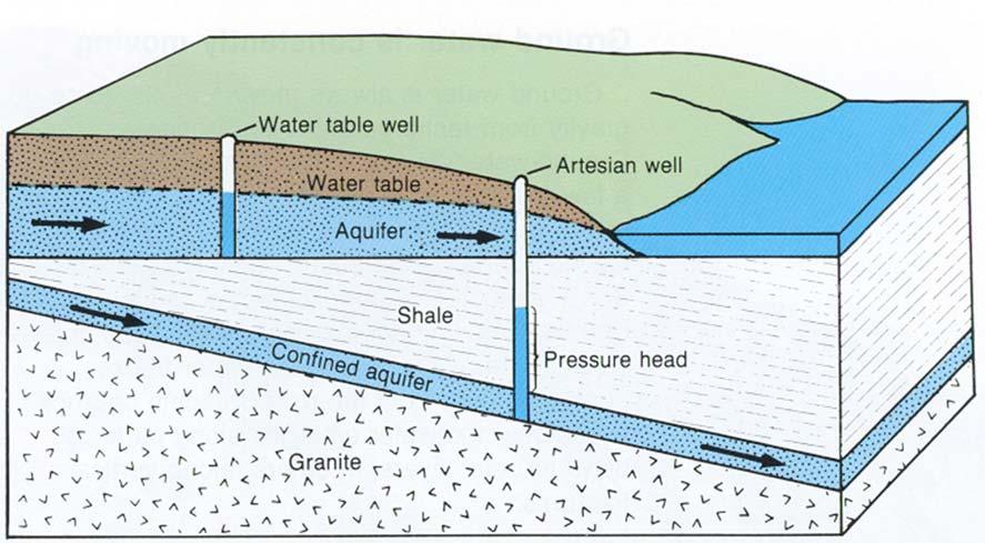
The radius, or circle of influence, of a well is an important factor in deciding the location of a new well. Wells should be located far enough apart that their circles of influence do not overlap. If they do overlap, pumping levels may be reduced in both wells.
Drawdown Profiles
Refer to Figure4.5 below.
1.Drawdown profile when well Number 1 is pumped alone.
2.Drawdown profile when well Number 2 is pumped alone.
3.Drawdown profile resulting from interference when both wells are pumped at the same time.
©2017, Texas A&M Engineering Extens ion Service. All rights reserved. PM 4 - 6
Groundwater Production Aquifers
Figure 4.4: Groundwater withdrawal. Source: USGS.
Groundwater Recharge
Aquifers are recharged by percolation from rain, snow, and seepage from rivers and lakes. Problems are occurring in many parts of the country where groundwater is withdrawn at a faster rate than it is replaced. This overpumping, called mining, results in declining water levels and, in some areas, subsidence, which is the sinking of the land.
Well Construction
Although water utility personnel are seldom involved in the construction of a new well, they are involved in using and maintaining the well. Thus, they should be familiar with the different types of wells and their parts. In addition, water utility personnel should be familiar with the development, testing, disinfection, operation, sanitation, and safety processes involving wells.
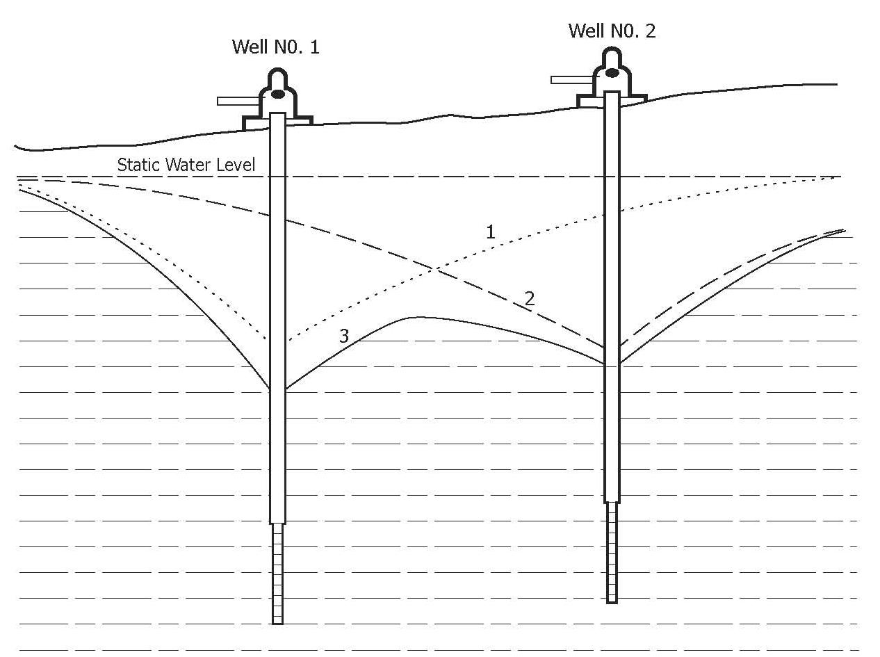
Groundwater Production Aquifers ©2017, Texas A&M Engineering Extens ion Service. All rights reserved. PM 4 - 7
Figure 4.5: Overlapping drawdown profiles. Source: TEEX.
Types of Wells
In the past, wells were dug with a shovel or bucket, bored with an auger, or driven with a drive point. Today, the drilled well is the most common type of well for public water supplies. The drilled well is constructed by the cable tool or rotary drill method.
Parts of a Well
The well casing and cementing protect the well from collapse and surface contamination.The well casing must be made from new carbon steel, high-strength, low-alloy steel, stainless steel, or plastic. It must conform to American Water Works Association (AWWA) standards.
The casing must extend down to the shallowest water-bearing formation. The casing is slipped into the hole and pressure cemented on the outside. Casing and cementing protect the well from collapse and surface contamination. The casing must extend 18 inches above the pump room floor or natural ground elevation (Figure 4.6).
The well screen is a slotted, drilled, or wire-wrapped pipe of corrosion-resistant material such as bronze or stainless steel. The purpose of the well screen is to keep sand out. The mesh size of the well screen opening is determined by the size of the material in the aquifer, the size of the gravel in the gravel pack, and the type of well development. The size of the openings is the most important feature of the well screen.
The gravel pack is made up of fine gravel placed around the well screen to reduce pumping sand. The size varies with the size of the material in the aquifer.
The well vent is a vacuum breaker that allows the casing to breathe as water levels change when the pump cycles and prevents a vacuum from being created. If a vacuum is allowed to form, it could draw contaminants into the well and also restrict the free flow of water to the well pump.
Well Sanitation and Safety
Contamination can come from sewage, industrial wastes, agricultural products, and many other sources.
•Abandoned wells in the area must be sealed.
•Completed wells must be protected by intruder-resistant fences or locked well houses.
•All public water supply wells must be provided with a concrete sealing block, a meter, a screened vent, and a sampling faucet.
Groundwater Production Aquifers ©2017, Texas A&M Engineering Extens ion Service. All rights reserved. PM 4 - 8
•Before a new well is placed in operation, it must be tested for bacteriological quality. Samples taken on three successive days must be free of coliforms.
•A well head must be properly installed (Figure4.6).
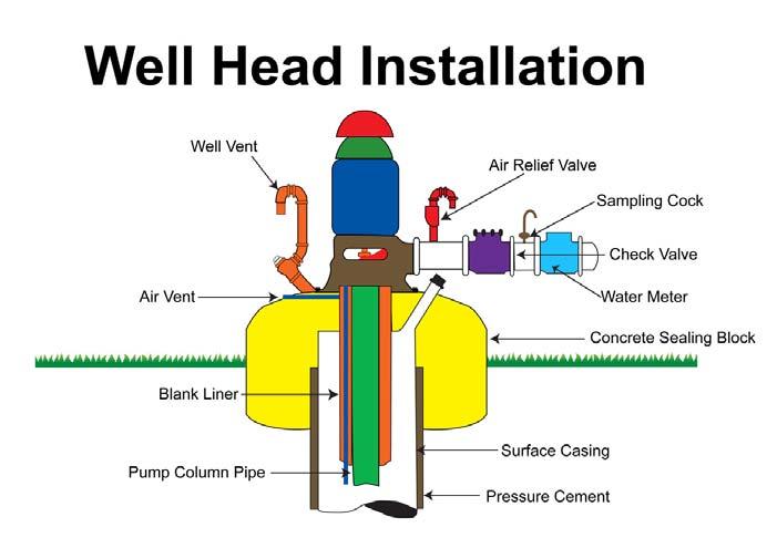
•A sanitary control easement within 150 feet of the well shall be secured from property owners and recorded in the county courthouse deed records.
–Wells must be a safe distance from wastewater lines, livestock, wastewater pumping stations, animal feed lots, and solid waste sites.
–No source of contamination shall be within 50 feet of a public well.
–Call the TCEQ for specific requirements. Figure4.7 illustrates the safe distances for public wells established by the TCEQ.
Groundwater Production Aquifers ©2017, Texas A&M Engineering Extens ion Service. All rights reserved. PM 4 - 9
Figure 4.6: Well head installation. Source: TEEX.
Developing a Well
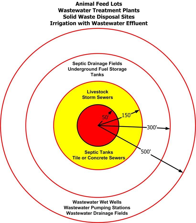
After construction, a well must be flushed out to remove drilling mud and loose sand.
Methods such as surging, overpumping, jetting, and backwashing may be used to develop the well. In any case, the pump used for development should not be the same one for permanent use in the well because it will be damaged by the sand and mud.
Groundwater Production Aquifers ©2017, Texas A&M Engineering Extens ion Service. All rights reserved. PM 4 - 10
Figure 4.7: Required safe distances from a well. Source: TEEX.
Testing
Well contract specifications must include tests and measurements after development. Tests are made over a period of time to provide well and pump efficiency rates and well capacity.
Sand Pumping
Wells can pump considerable amounts of sand. Reasons for sand problems include improper well development, loss of gravel pack, excessively large screen openings or broken screens, corrosion of screen or casing, and overpumping.
Sand pumping can be reduced by the following:
•lowering the gpm pump rate
•cycling the pump less
•installing sand separation devices
•correcting problems such as loss of gravel pack
Disinfecting Wells
After developing and testing, a well must be disinfected with a chlorine dosage of at least 50 mg/L before use. The chlorine must be mixed with the well water and the solution allowed to stand for six hours or more.
The chlorinated water is pumped out and a sample taken for bacteriological analysis. The water cannot be used until samples taken on three successive days show “no coliform organisms found.” A sample for physical and chemical analysis must be collected after 36 hours of continuous pumping.
Remember, disinfection is not for the water in the aquifer. Disinfection is for the pump, gravel, and screen.
Well Supply Operation
The water level with the pump running is called the pumping level. The water level without the pump running is called the static level. The difference between these two measurements is called the drawdown. Water levels can be checked with a tape, an airline, or an electric sounder (most accurate). Changes in water levels or the amount of water produced can alert the operator to a drop in the water table, screen stoppage, or damage to the pump.
Groundwater Production Aquifers ©2017, Texas A&M Engineering Extens ion Service. All rights reserved. PM 4 - 11
Pumps and Motors
The most common types of deep well pumps are the submersible and the vertical turbine (Figure4.8 and Figure4.9). The vertical turbine is a type of line shaft, centrifugal pump that is water or oil lubricated. A water-lubricated pump requires the bearings to be wet and the water line in operation before starting the pump. Otherwise, immediate damage can result. Shallow wells may use jet pumps when the amount of water to be delivered is small.
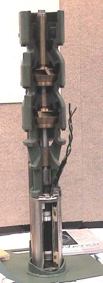
Groundwater Production Aquifers ©2017, Texas A&M Engineering Extens ion Service. All rights reserved. PM 4 - 12
Figure 4.8: Submersible vertical turbine pump. Source: TEEX.
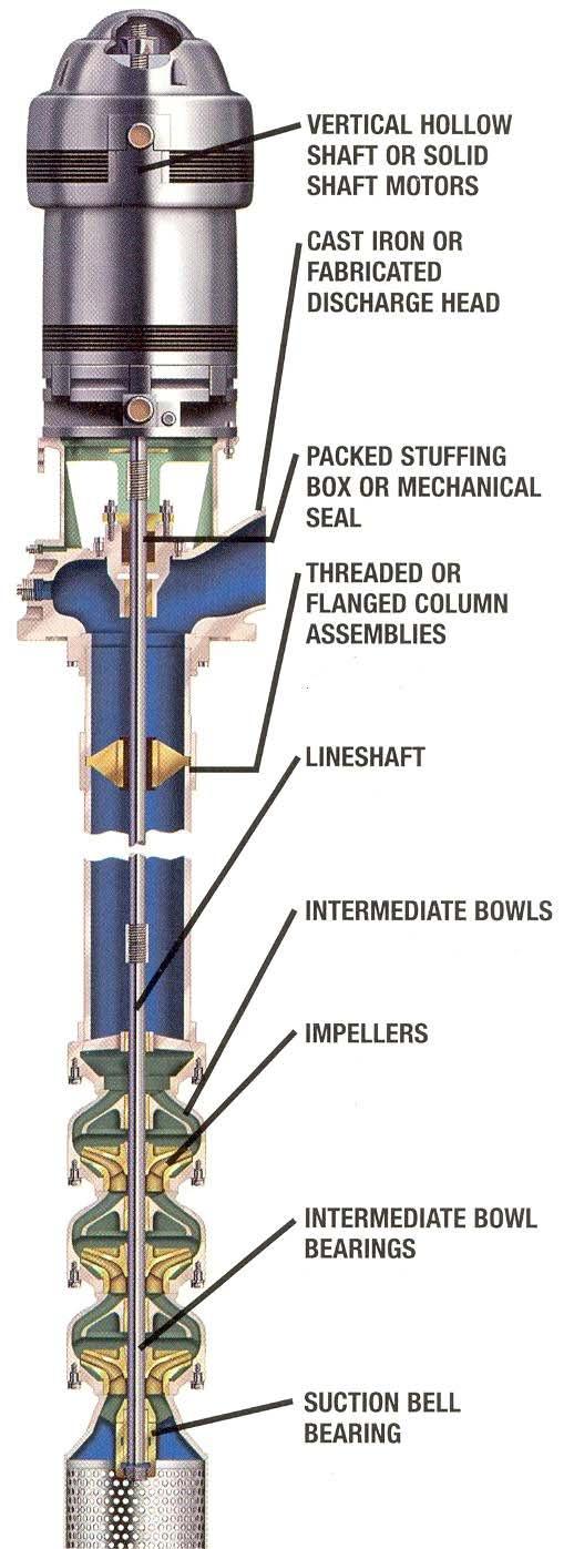
Groundwater Production Aquifers ©2017, Texas A&M Engineering Extens ion Service. All rights reserved. PM 4 - 13
Figure 4.9: Source:LayneChristensen,Inc.and ITT-GouldsPumps.
Groundwater Treatment
Groundwater is generally wellfiltered and free of turbidity, color, and organic contamination. However, groundwater may be high in minerals, gases, or corrosives. Groundwater may require extensive treatment depending on the impurities present.
Aeration
Aeration is a method that can be used to remove or reduce certain contaminants from water. Cascade aerators, packed air-stripping towers, and air diffusers are used to aerate water.
Gases such as methane, carbon dioxide, and hydrogen sulfide can be reduced by aeration. Hydrogen sulfide, which has a rotten egg odor, is oxidized by super-chlorination. Aeration is also effective in reducing water temperature if the groundwater is hot.
Aeration can also be used to remove iron and manganese from the water supply. Iron levels above 0.3 mg/L cause red stains on clothing, colored water, or turbidity. Excess manganese can cause black stains. Water aerated or chlorinated at proper pH levels oxidizes the iron and manganese, turning them into solid particles. Filtration then removes the particles, producing clear water.
Another method of iron control is the use of sequestering agents such as polyphosphates. Sequestering does not remove iron from the water, but prevents it from combining with oxygen and reddening.
Corrosion Control
Well water is sometimes corrosive. Low pH, dissolved gases, high temperatures, and high mineral levels can cause this. Aeration and pH adjustment with sodium hydroxide or soda ash reduces corrosiveness.
Softening
Softening removes calcium and magnesium by adding lime or by exchanging ions (an atom or group of atoms). Ion exchange replaces calcium ions with sodium ions.
Softening is costly, but ion exchange, demineralizers (a form of ion exchange), and reverse osmosis are used for homes, businesses, or industries.
Groundwater Production Groundwater Treatment ©2017, Texas A&M Engineering Extens ion Service. All rights reserved. PM 4 - 14
Special Treatment Processes
Processes are available for removing arsenic, fluoride, lead, mercury, nitrate, and silver. Coagulation followed by sedimentation and filtration is effective. Reverse osmosis, a process that forces water through a membrane (a sheet of synthetic material) under pressure, is also effective. The membrane prevents passage of dissolved minerals and larger particles, and ejects them in a waste stream.
Surface Water Influence of Wells
Surface Water Treatment Rule
The Surface Water Treatment Rule (SWTR) requires community and non-community wells, springs, and infiltration galleries (a subsurface tunnel that collects groundwater) to determine possible direct influence of surface water.
Changes in groundwater quality can indicate influence of surface water. Surface water organisms such as Giardia cysts, algae, or other microorganisms prove direct influence.
How to Evaluate Surface Water Influence
Procedures for evaluating the influence of surface water on a water supply focus on shifts in water quality such as turbidity, temperature, pH, and the presence of surface water organisms. When shifts in water quality correlate with rainfall or surface water conditions, direct influence by surface water is indicated.
Extensive evaluation is not required if well is:
•deeper than 50 feet and more than 200 feet from a nearby surface water body,
•constructed properly,
•screened or perforated below a confining bed, and
•has no water quality shifts, coliform contamination, or indicated disease outbreaks.
Groundwater Production Groundwater Treatment ©2017, Texas A&M Engineering Extens ion Service. All rights reserved. PM 4 - 15
Summary
This module has provided you with a description of the sources of groundwater. After reading this module, you should have a knowledge of the various attributes of aquifers and the methods for extracting the water from this type of underground source. In addition, you should be able to describe how groundwater is treated and made potable for public use.
Groundwater Production Summary ©2017, Texas A&M Engineering Extens ion Service. All rights reserved. PM 4 - 16
Module 4 Review Questions
1.Aquifers are underground, water-bearing formations yielding useful quantities of water.
a.true
b.false
2.The quantity of water a formation yields depends on the thickness and permeability of the formation.
a.true
b.false
3.Problems caused by overpumping are declining water levels and subsidence.
a.true
b.false
4.Well casing and cementing protect the well from collapse and surface contamination.
a.true
b.false
5.The purpose of the well screen is to keep out birds and insects.
a.true
b.false
6.The most important feature of the well screen is the length.
a.true
b.false
7.The mesh size of the screen is determined by the size of the aquifer material, the size of the gravel in the gravel pack, and the type of well development.
a.true
b.false
8.The gravel pack is fine gravel placed around the screen to reduce pumping bacteria.
a.true
b.false
Groundwater Production Module 4 Review Questions ©2017, Texas A&M Engineering Extens ion Service. All rights reserved. PM 4 - 17
9.The well vent is a vacuum breaker allowing the casing to breathe as water levels change when the pump cycles.
a.true
b.false
10.All public wells must be provided with a steel sealing block, a meter, a screened vent, and a sampling faucet.
a.true
b.false
11.No source of contamination is allowed within 500 feet of a public well.
a.true
b.false
12.One way to reduce sand pumping is to increase the pump rate and cycle more.
a.true
b.false
13.Water from a new well must not be used until bacteriological samples on three successive days show coliform found.
a.true
b.false
14.The water level without the pump running is called the static level, the water level with the pump running is called the pumping level, and the difference between the two is called the dropdown.
a.true
b.false
15.Groundwater usually contains more dissolved minerals and gases than surface water, but fewer ________.
a.microorganics
b.microorganisms
c.corrosives
d.dissolved solids
©2017, Texas A&M Engineering Extens ion Service. All rights reserved. PM 4 - 18
Groundwater Production Module 4 Review Questions
16.Water table wells are usually ________ wells.
a.deep wells
b.artesian
c.shallow
d.all listed
17.In a water table well, the cone of depression is a ________ area around the well.
a.dewatered
b.depressed
c.deflated
d.developed
18.A sanitary control easement must cover land within ________ feet of a public well.
a.15,000
b.1,500
c.150 d.15
19.Livestock and septic tanks must be no closer than ________ feet to a public well.
a.5,000
b.500
c.50 d.5
20.Underground fuel tanks and septic drainage fields must be at least ________ feet from a public well.
a.15,000
b.1,500
c.150 d.15
Groundwater Production Module 4 Review Questions ©2017, Texas A&M Engineering Extens ion Service. All rights reserved. PM 4 - 19
21.Feedlots, sewage treatment plants, and landfills must be at least ________ feet from a public well.
a.50
b.500
c.5,000
d.50,000
22.A well may be developed by surging, overpumping, jetting, and ________.
a.backwashing
b.backflushing
c.backflooding
d.backfilling
23.To disinfect a new well, a chlorine dosage of at least ________ mg/L of chlorine is required.
24.A sample for physical and chemical analysis must be taken after ________ hours of pumping.
a.3
d.63
25.Changes in well water levels or the volume of water produced can alert the operator to a drop in the water table, screen stoppage, or damage to the ________.
a.sealing block
b.pump
c.vent
d.sampling faucet
Production Module
Review
©2017, Texas A&M Engineering Extens ion Service. All rights reserved. PM 4 - 20
Groundwater
4
Questions
a.5 a.10 b.25 c.50
b.6 c.36
26.Common deep well pumps include the ________ and the vertical turbine.
a.submarine
b.subsidence
c.submission
d.submersible
27.Gases such as methane, carbon dioxide, and hydrogen sulfide are reduced by ________.
a.backwashing
b.sequestering
c.aeration
d.softening
Groundwater Production Module 4 Review Questions ©2017, Texas A&M Engineering Extens
Service. All rights
PM 4 - 21
ion
reserved.
Groundwater Production Module 4 Review Questions ©2017, Texas A&M Engineering Extens ion Service. All rights reserved. PM 4 - 22
Surface Water Production
Terminal Objective
Upon the successful completion of this module, the participant will be able to describe how surface water is made usable.
Enabling Objectives
1.List the major Texas regulations that govern surface water.
2.Describe the surface water treatment process.
3.Explain surface water treatment rules.
©2017, Texas A&M Engineering Extens ion Service. All rights reserved.
Module
Surface Water Production ©2017, Texas A&M Engineering Extens ion Service. All rights reserved. PM 5 - 2
Introduction
Rivers, lakes, and reservoirs are surface water sources, and are broadly grouped into the following three categories:
•Rivers
•Natural lakes
•Man-made lakes
Texas has 23 major river basins, according to TWDB, with the Rio Grande being the longest, running 1,250 miles along the Mexico border (Figure5.1). The U.S. Geological Survey identifies about 3,700 Texas streams. The combined length of these streams is about 80,000 miles and drain 263,513 square miles within Texas.
This module provides an overview of surface water production. State regulations and the treatment required to change surface water to quality water will be discussed.
Surface Water Production Introduction ©2017, Texas A&M Engineering Extens ion Service. All rights reserved. PM 5 - 3
Sources of Surface Water
Texas has 204 major reservoirs and more are planned. A major reservoir contains at least 5,000 acre-feet. One acre-foot is an acre by one foot deep and equals 325,851 gallons.
All major reservoirs in Texas are man-made except Caddo Lake, which is located on the Texas-Louisiana border 30 miles northeast of Marshall. The largest reservoir within Texas is Sam Rayburn, located about 30 miles east of Lufkin.
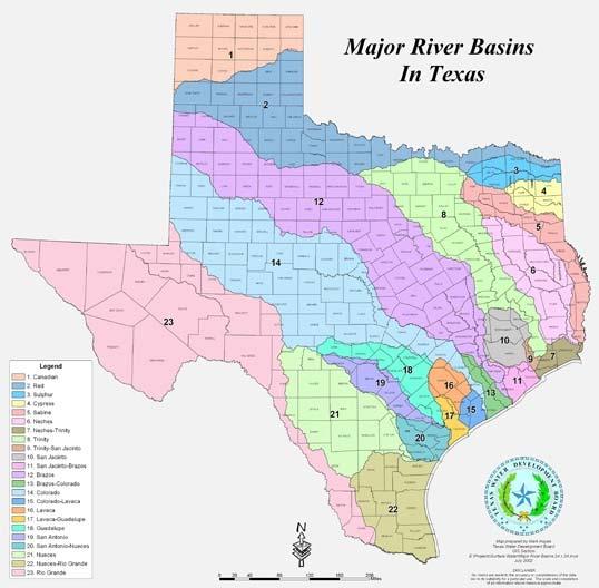
Introduction ©2017, Texas A&M Engineering Extens ion Service. All rights reserved. PM 5 - 4
Surface Water Production
Figure 5.1: Major river basins. Source: Texas WaterDevelopmentBoard.
Only 40% of public water systems use surface water, but they serve 3/4 of the population. Therefore, large cities tend to use surface water. San Antonio, the third largest city in Texas, is an exception. San Antonio uses groundwater from the Edwards aquifer.
Protecting Surface Sources
Bacteria, algae, and chemicals are common contaminants of surface water. Contamination comes from sewage treatment plant effluent, seepage from septic tank drainfields, and runoff from agricultural areas containing pesticides and fertilizers.
Water utility operators can control contamination by inspecting watersheds regularly, controlling erosion to reduce river silt, controlling algae, fencing reservoirs when possible, and marking water treatment plant intakes with buoys.
State Regulation of Surface Water
In Texas, the TCEQ has established the following regulations:
•Shore installations, marinas, boats, and houses on the watershed must have sewage disposal.
•Septic tanks, absorption fields, sewers, manholes, or toilets cannot be within 75 feet of a lake at spillway elevation or the 50-year flood elevation.
•Plant intakes shall have screens and grates to minimize the amount of debris entering the plant.
•No boat ramps, marinas, docks, or fishing piers can be within 1,000 feet of an intake.
•All activities shall be restricted within 200 feet of an intake.
Treatment of Surface Water
Water from large lakes may be low in bacteria and organic matter while river water can be high in bacteria and other contaminants. Most surface water is low in minerals, gases, and dissolved solids, but turbidity and algae are common problems.
Objectives of Surface Water Treatment
To protect the health of the community, treated water must be free of disease-causing organisms and harmful chemicals must be reduced to safe levels.
Surface
©2017, Texas A&M Engineering Extens ion Service. All rights reserved. PM 5 - 5
Water Production Treatment of Surface Water
To supply an aesthetically pleasing product, water must be low in color, turbidity, suspended solids, temperature, and free of taste and odor.
To protect consumer property, water should not be corrosive, deposit scale, or stain plumbing. Colored water can be caused by organics, algae, iron, or manganese.
Because characteristics of water sources may vary greatly, the following are indicated properties of quality water:
•An absence of harmful chemicals
•An absence of disease-causing organisms
•Little or no color, turbidity, solids, odor, or taste
•Noncorrosive, nonstaining, and non-scale forming
Required Treatment
Treatment can include aeration, screening, chemical oxidation, coagulation, flocculation, sedimentation, filtration, and disinfection. Treatment required by the TCEQ (290.42(d)(1) for all surface water includes the following:
•Pretreatment disinfection
•Taste and odor control
•Coagulation
•Sedimentation
•Filtration
•Terminal disinfection
•Covered storage (clear well storage)
Pretreatment Processes
Surface water is pretreated to remove taste and odor or contaminants such as turbidity. Pretreatment removes materials that affect treatment methods. Pretreatment includes:
•reservoir destratification,
•control of algae,
•debris removal,
•presedimentation,
•aeration,
©2017, Texas A&M Engineering Extens ion Service. All rights reserved. PM 5 - 6
Surface Water Production Treatment of Surface Water
•chemical oxidation, and
•activated carbon adsorption.
Reservoir Destratification
Deep reservoirs become stratified by temperature differences where cold water is trapped below warmer water. Stratified reservoirs can have problems with algae, iron and manganese, and hydrogen sulfide. Injection of air at the bottom of the reservoir (from spring to fall) will result in mixing to destratify the lake.
Chemical Control of Algae
With enough sunlight and nutrients, algae can bloom in a reservoir, causing taste and odor problems and affecting chemical and biological changes in water quality. Using copper sulfate at dosages of 0.1 to 0.5mg/L and approved algaecides will assist in controlling algae blooms.
Debris Removal
Screening at the raw water intake prevents debris from damaging pumps or blocking transmission lines. Screens can be manually or mechanically cleaned.
Presedimentation
Rivers or shallow reservoirs can have heavy silt loads during high flows or rainfall. Presedimentation in reservoirs or sedimentation basins are effective in reducing turbidity.
Aeration
Aeration is the incorporation of air into the water by means of spray nozzles, steps or cascades, or trays or diffusers.
Aeration removes tastes, odors, certain organics and gases, and oxidizes iron and manganese.
Chemical Oxidation
Chemical oxidation destroys microorganisms and assists in reducing taste and odor problems. Chemical oxidants commonly used are chlorine, potassium permanganate, chlorine dioxide, and ozone. These oxidants may also kill algae, oxidize iron and manganese, and reduce organic chemicals.
Surface Water Production Treatment of Surface Water ©2017, Texas A&M Engineering Extens ion Service. All rights reserved. PM 5 - 7
Surface Water Production
Treatment of Surface Water
Activated Carbon Adsorption
Bacteria or algae are a major cause of taste and odor problems. The most effective treatment is adsorption utilizing activated carbon. Carbon is applied at the raw water pumping station or in the rapid mix. The surface structure of activated carbon will trap and hold organic material. Sedimentation and filtration remove the carbon and its bonded organics.
Chemical Treatment Processes
Chemical Addition
Chemical feeders meter and add chemicals at a uniform rate (Table5.1). Dry chemicals can be added gravimetrically, volumetrically, or in solution. Temperatures affect the rate of chemical reaction. The higher the temperature, the faster the reaction. Temperature will also affect mixing and flow patterns.
Chemical pump feedrate is determined by measuring the solution withdrawn from a marked cylinder over time. The volume dispensed in one minute can be compared to the desired rate, and the pump adjusted accordingly.
Name
Sodium aluminateCoagulant
Aluminum sulfate (alum) Coagulant
Ferrous sulfateCoagulant
Ferric chloride Coagulant
Purpose
Calcium hydroxide (lime)pH adjustment, softening, aid to coagulation
Sodium carbonate (soda ash) Softening, removal of heavy metals, aid to coagulation, pH and alkalinity adjustment
Polyphosphates (calgon)Stabilization, prevents red water
Copper sulfate (blue stone) Algae control
PolyelectrolytesAid to coagulation
Activated silica Aid to coagulation
Activated carbonRemoval of tastes, odor, organics
Fluorosilic acid, Sodium silicofluoride, Sodium fluoride Fluoride addition, prevents tooth decay
©2017, Texas A&M Engineering Extens ion Service. All rights reserved. PM 5 - 8
Table 5.1: Chemicals Commonly Used in Water Treatment
Coagulation and Flocculation
The processes of chemical mixing, coagulation, flocculation, and sedimentation remove suspended and dissolved materials from water. These processes are commonly used for surface water, but can be used to remove hardness or iron in groundwater.
First, chemicals are mixed with the water in a rapid mix zone. The chemicals cause particles in the water to coagulate and to form floc. Then, the water passes into a tank where mixers slowly agitate the water. This process, known as flocculation, causes the floc to form larger particles that will settle more readily.
Common coagulating chemicals are alum, ferrous sulfate, and ferric chloride. Lime or soda ash raise or lower the pH and polymers are used to enhance the coagulation and flocculation. Jar tests assist the operator in determining which chemical, and how much, to apply. Turbidity, pH, temperature, alkalinity, and chemical dosage affect coagulation.
The amount and characteristics of suspended materials in raw water will influence coagulation. For example, highly turbid waters, where the turbidity is heavy, generally require less coagulant due to the increase in interparticle collisions.
Very low turbidity waters, however, where the turbidity is of a colloidal nature, are difficult to coagulate. Very finely suspended solids (turbidity) will require increased coagulant dosages.
The pH of the water to be coagulated is perhaps the single most important factor in effective coagulation. Each coagulant has an optimum pH range in which the best coagulation takes place. Failure to operate within optimum pH range for given water may waste chemicals and result in a poor quality effluent.
Usually, the colder the water, the slower the chemical reaction of coagulation. As temperature decreases, the viscosity of the water increases and the rate of floc settling is decreased.
The alkalinity of water is its quantitative capacity to neutralize a strong acid to a designated pH. The test provides results used in calculating the chemical dosages needed in coagulation and softening processes. Chemical dosages will be determined by a series of jar tests. The chemical dosage should be such that no concentrations over 10 NTU, preferably as low as 5 NTU, shall go onto the filter (Figure 5.2).
If coagulation and flocculation are conducted properly, the sedimentation and filtration that follow will reduce suspended solids and colloidal materials (turbidity) to very low levels.
Surface Water Production Treatment of Surface Water ©2017, Texas A&M Engineering Extens ion Service. All rights reserved. PM 5 - 9
Jar testing is a device used to determine the effectiveness of chemical coagulation of water that can be experimentally evaluated in the laboratory (Figure5.2). The jar tester usually has six paddles that have the ability to adjust the revolution from 0 to 100 rpms. In making the test, one liter or more is placed in each jar. While stirring at around 80 to 100 rpms a chemical coagulant is added and mixed for approximately one minute, reduced to 25 to 30 rpms for 20 to 30 minutes, and then turned off.
The operator then observes the characteristics of the floc as it settles. A hazy sample indicates poor coagulation, while proper coagulation indicates a well-formed floc that settles, leaving a clear liquid. The lowest dosage that provides a good turbidity removal during the jar test is considered the first trial dosage in plant operation. A full-scale coagulation and flocculation process can be conducted for a wide range of conditions.
Coagulation and flocculation are sensitive to many variables, such as the nature of the turbidity-producing substances, type and dosage of coagulant, pH of the water, temperature and viscosity of the water, alkalinity and hardness, and other variables. The purpose of running variations in mixing, dosages, and settling rates is help produce a floc that is resistant to shear and breakup during flocculation as it moves through the train or stages. The TCEQ considers a maximum turbidity of 10 NTUs as acceptable going onto the filter; 5 NTUs is good and 2 or fewer is optimized, producing a filter effluent of 0.1 NTU.
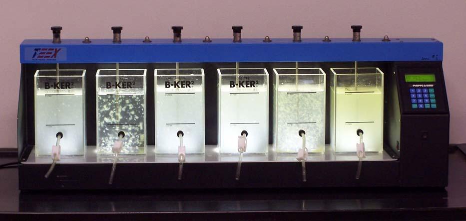
Surface Water Production Treatment of Surface Water ©2017, Texas A&M Engineering Extens ion Service. All rights reserved. PM 5 - 10
Figure 5.2: Jar sequence test. Source: TEEX.
Sedimentation
After the floc forms, the water flows into a sedimentation basin. This basin allows the water to settle to a quiet state. A detention time of at least six hours is required to allow the floc to settle. The settled floc, called sludge, is removed from the basin periodically.
Sedimentation is accomplished in either square, rectangular, or circular tanks. Sludge blanket clarifiers (upflow clarifiers) mix, coagulate, flocculate, and settle in the same unit. The flow rises through the sludge blanket, encouraging filtering and settling. Zones in a settling tank include the inlet, outlet, settling, and sludge zones.
Factors influencing sedimentation include:
•floc size and shape—floc is too large and has poor settling qualities;
•water temperature—the colder the water temperature, the greater the density and the more resistant to floc setting;
•floc-specific gravity—the heavier the floc, the better it settles. Floc that is too heavy may settle too rapidly, leaving colloidal matter in suspension;
•detention time—the basin volume must provide at least six hours detention time;
•velocity—volume and tank shape must maintain velocities of 0.01 to 0.03 feet per second; and
•short-circuiting—short-circuiting shortens detention time and increases water velocity.
Sludge Disposal
Thick sludge blankets must not be allowed to form in sedimentation basins because they could:
•create taste and odor problems;
•reduce the capacity of the settling tank;
•form gas and cause floating solids; or
•change the chemical quality of the water.
Sludge is disposed of in lagoons, discharged into sanitary sewers, or dewatered and hauled to sanitary landfills.
Surface Water Production Treatment of Surface Water ©2017, Texas A&M Engineering Extens ion Service. All rights reserved. PM 5 - 11
Filtration
If coagulation, flocculation, and sedimentation are effective, filtering will remove remaining suspended solids and pathogens such as Giardia and Cryptosporidium, which are chlorine resistant. Filtration is the final step in removing suspended matter and chlorine-resistant microorganisms (Figure5.3).
A filter has 24 to 30 inches of porous material such as sand or anthracite coal, called filter media. The filter bottom and gravel support the filter media. A common filter is the rapid sand filter, which has several layers of differently sized media. These units filter 2 gallons per minute per square foot of filter media.
The parts of a rapid sand filter are as follows:
•Filter box
•Wash water troughs
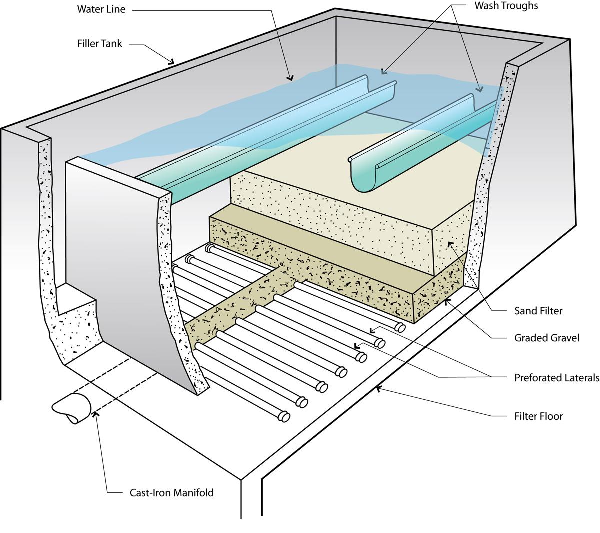
Surface Water Production Treatment of Surface Water ©2017, Texas A&M Engineering Extens ion Service. All rights reserved. PM 5 - 12
Figure 5.3: Sand filter. Source: TEEX.
•Inlets and outlets
•Underdrains
•Valves and piping
•Filter agitators (surface wash)
•Loss-of-head gauge
•Rate-of-flow controllers
As water percolates through the media, the filter will gather solids (Figure5.4). As the solids increase, there will be a loss of head (pressure) through the filter due to increased friction. When this head loss is about 6 to 10 feet, the filter must be backwashed. Operators may use other criteria such as filter effluent turbidity or length of filter time to decide when to backwash.
While the backwash is taking place, the filter bed should expand 30% to 50% to ensure good scouring action. If backwashing is done improperly, mud balls form in the media, causing it to crack and clog up. Pressure sand filters have the media and underdrains enclosed in a steel tank. The media is similar to that in gravity sand filters. Filtration rates range from 2 to 4 gallons per minute per square foot of filter media. The state requires pressure filters to operate at 2 gpm per square foot.
Pressure filters are used in small systems, swimming pools, and industrial plants. Pressure filter media is not easily inspected and problems may go uncorrected.
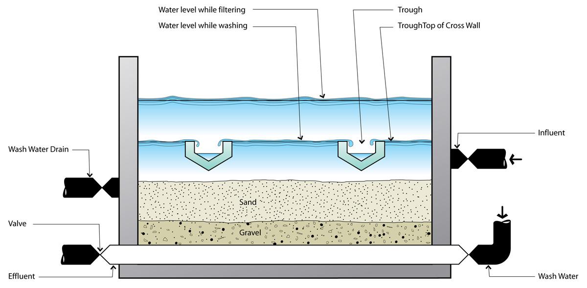
Surface Water Production Treatment of Surface Water ©2017, Texas A&M Engineering Extens ion Service. All rights reserved. PM 5 - 13
Figure 5.4: Sand filter cutaway. Source: TEEX.
Filter problems may involve the following:
•Mud balls, which clog a filter
•Cracks and channeling, which allow bypassing of the filtering action
•Damaged underdrains, causing poor filtering and backwash
•Air collected in the underdrains and media (air-binding) that leads to damage during backwashing
Disinfection of Surface Water
Because surface water is likely to contain pathogens along with turbidity, which can harbor pathogens, adequate disinfection is critical. Disinfection is the process of destroying or inactivating pathogenic agents. The TCEQ requires the following:
•Disinfection of surface water prior to storage
•Facilities for pretreatment disinfection and terminal disinfection
•Standby disinfecting equipment and excess capacity (50% greater than the highest expected dosage)
Chemicals used to disinfect include chloramine, chlorine, chlorine dioxide, and ozone. Chlorination of surface water may lead to the formation of trihalomethanes and haloacetic acids. To avoid these, chloramine, ozone, or chlorine dioxide may be used for pretreatment disinfection and chloramine for post-disinfection.
Clear Well Storage
Treated water is stored at the plant in the clear well. The clear well provides detention time for disinfection and extra storage.
Surface Water Treatment Rules
Turbidity
A system's filtered water must be less than or equal to 0.3 Nephlometric Turbidity Units (NTU) in at least 95% of the measurements taken each month, and no sample can exceed one NTU. Systems serving less than 500 persons may reduce turbidity sampling to once per day (Table5.2).
©2017, Texas A&M Engineering Extens ion Service. All rights reserved. PM 5 - 14
Surface Water Production Surface Water Treatment Rules
Disinfection
The combination of treatment and disinfection must achieve at least 99.9% inactivation/removal of Giardia lamblia cysts and at least 99.99% inactivation/removal of viruses. The filtered water must be continuously monitored for adequate disinfection levels. Inadequate disinfection must be reported to the state the next business day.
The disinfection residual must be measured at the same points and times in the distribution system as total coliform sampling. No more than 5% of the distribution samples can have inadequate residuals for two consecutive months.
Systems serving 3,300 or fewer persons can take grab samples in lieu of continuous disinfection monitoring at the frequencies indicated in Table5.2.
Tracer Studies
To assess the adequacy of disinfection contact time, tracer study data must be submitted to the state.
When Surface Water Influences Well Water
Wells less than 50 feet in depth and wells in limestone formations and springs must be evaluated for surface water organisms and debris. Sources exhibiting surface water contamination are required to install treatment. Minimum treatment is coagulant addition, filtration, clearwell storage, plus surface water disinfection and monitoring requirements already noted.
Fluoridation
Fluoride in drinking water is beneficial or detrimental depending on the amount present. Studies indicate moderate levels of fluoride (0.7 to 1.0 mg/L) reduce cavities and dental care costs. Waters high in natural fluoride (above 2.0 mg/L) cause mottling (a brown stain) of the enamel.
©2017, Texas A&M Engineering Extens ion Service. All rights reserved. PM 5 - 15
Surface Water Production Surface Water Treatment Rules
System Population Chlorine Residual Samples Per Day <5001 501–1,000 2 1,001–2,5003 2,501–3,300 4
Table 5.2: Chlorine Monitoring Frequencies
Sodium fluoride, sodium silicofluoride, and fluorosilic acid are fluoride compounds added to water supplies. These compounds are fed in controlled amounts by chemical pumps as the water goes to storage. Excessive fluoride is reduced by activated alumina contact beds, demineralizers, reverse osmosis, and other methods. These are expensive techniques and are rarely used.
Summary
Treated surface water becomes drinking water after a lengthy process governed by state regulatory agencies. In the next module, we will discuss the disinfection of water.
Production Summary ©2017, Texas A&M Engineering Extens ion Service. All rights reserved. PM 5 - 16
Surface Water
Module 5 Review Questions
1.Water from rivers, lakes, and reservoirs is called groundwater.
a.true
b.false
2.Fifty percent of public water systems use surface water.
a.true
b.false
3.Boat ramps, marinas, and docks should not be located within 1,000 feet of a water intake.
a.true
b.false
4.Surface water contains bacteria, algae, and turbidity, but is low in minerals, gases, and dissolved solids.
a.true
b.false
5.The objectives of water treatment are protecting of public health, supplying an aesthetically pleasing product, and protecting consumer property.
a.true
b.false
6.The TCEQ requires surface water to have pretreatment, pre-disinfection, taste and odor control, coagulation, sedimentation, filtration, covered storage, and terminal disinfection.
a.true
b.false
7.Methods for controlling taste and odor problems are lake destratification, algae control, aeration, chemical oxidation, and activated carbon.
a.true
b.false
8.One of the causes of taste and odor problems is algae and bacteria.
a.true
b.false
Surface Water Production Module 5 Review Questions ©2017, Texas A&M Engineering Extens ion Service. All rights reserved. PM 5 - 17
9.Coagulants are sodium aluminate, aluminum sulfate, ferrous sulfate, and sodium chloride.
a.true
b.false
10.Coagulants cause small particles in water to clot together forming floc, and this process, flocculation, forms larger particles that settle more readily.
a.true
b.false
11.Bucket tests help the operator determine the chemical and dosage to apply.
a.true
b.false
12.Turbidity, pH, temperature, alkalinity, and chemical dosage affect coagulation.
a.true
b.false
13.To remove suspended solids and chlorine-resistant microorganisms, surface water must be disinfected.
a.true
b.false
14.Filtering is the final step in removing suspended matter and chlorine-resistant microorganisms.
a.true
b.false
15.A common filter is the slow sand filter, having several layers of differently sized media.
a.true
b.false
16.A filter must be whitewashed when a head loss of 6 to 10 feet occurs.
a.true
b.false
Water Production Module 5 Review
©2017, Texas A&M Engineering Extens ion Service. All rights reserved. PM 5 - 18
Surface
Questions
17.Most surface water is low in minerals, gases, and ________.
a.algae
b.turbidity
c.dissolved solids
d.bacteria
18.Quality water has low amounts of color, turbidity, solids, and ________.
a.oxygen
b.taste and odor
c.hydrogen
d.all listed
19.Pretreatment includes lake destratification, control of algae, debris removal, presedimentation, aeration, ________, and activated carbon adsorption.
a.chemical oxidation
b.filtration
c.terminal disinfection
d.backwashing
20.Copper sulfate in dosages of ________ and approved algaecides control algae blooms.
a.10 to 50 mg/L
b.1 to 5 mg/L
c.0.1 to 0.5 mg/L
d.0.01 to 0.05 mg/L
21.The most effective treatment for taste and odor is adsorption with ________.
a.activated carbon
b.chlorine
c.ferric chloride
d.copper sulfate
Surface Water Production Module 5 Review Questions ©2017, Texas A&M Engineering Extens ion Service. All rights reserved. PM 5 - 19
22.Lime is applied to water to ________.
a.coat water mains
b.adjust pH or alkalinity
c.prevent tooth decay
d.prevent algae
23.The process of using chemicals to clot particles together is called ________.
a.sedimentation
b.filtration
c.coagulation and flocculation
d.all listed
24.Detention time in sedimentation basins must be at least ________ hours to allow floc to settle.
a.six
b.five
c.four
d.three
25.Factors affecting sedimentation are weight of the floc, ________, detention time, and short-circuiting.
a.water temperature
b.water velocity
c.taste and odor
d.a and b
26.Backwashing should expand the filter bed by ________%.
a.5 to 10
b.15 to 20
c.25 to 30
d.30 to 50
Production
©2017, Texas A&M Engineering Extens ion Service. All rights reserved. PM 5 - 20
Surface Water
Module 5 Review Questions
27.A common filter problem is ________, prevented by proper backwashing.
a.ice
b.mud balls
c.detention time
d.coagulation
28.Chemicals used in disinfection are chloramine, chlorine, chlorine dioxide, and ________.
a.ferrous sulfate
b.copper sulfate
c.activated carbon
d.ozone
Surface Water Production Module 5 Review Questions ©2017, Texas A&M Engineering Extens
Service.
PM 5 - 21
ion
All rights reserved.
©2017, Texas A&M Engineering Extens ion Service. All rights reserved. PM 5 - 22
Surface Water Production Module 5 Review Questions
Disinfection
Terminal Objective
Upon the successful completion of this module, the participant will be able to summarize the process for the disinfection of water.
Enabling Objectives
1.Outline the processes related to the microbiological quality of water.
2.Explain the various facets of chlorination.
3.Give examples of alternative disinfectants.
©2017, Texas A&M Engineering Extens ion Service. All rights reserved.
Module
Disinfection ©2017, Texas A&M Engineering Extens ion Service. All rights reserved. PM 6 - 2
Introduction
Disinfection destroys disease-causing microorganisms called pathogens. Disinfection kills pathogens without sterilization, which kills all microorganisms. Sterilizing drinking water is not necessary because most microorganisms are not pathogens.
The process of disinfection of water includes statistical sampling, comparison with regulatory requirements, and an acceptable application of chemical disinfection. We will examine chlorine application and personal safety precautions in detail.
Microbiological Quality
Revised Total Coliform Rule
The Environmental Protection Agency (EPA) published the Revised Total Coliform Rule (RTCR) in the Federal Register (FR) on February 13, 2013 (78 FR 10269) and minor corrections on February 26, 2014 (79 FR 10665). The RTCR is the revision to the 1989 Total Coliform Rule (TCR) and is intended to improve public health protection.
All public water systems (PWSs) must comply with the RTCR starting April 1, 2016, or an earlier state effective date. Until then, PWSs must continue complying with the 1989 TCR.
Total coliforms are a group of related bacteria that are (with few exceptions) not harmful to humans. A variety of bacteria, parasites, and viruses, known as pathogens, can potentially cause health problems if humans ingest them. EPA considers total coliforms a useful indicator of other pathogens for drinking water. Total coliforms are used to determine the adequacy of water treatment and the integrity of the distribution system.
Key provisions of the RTCR include:
•Setting a maximum contaminant level goal (MCLG) and maximum contaminant level (MCL) for E. coli for protection against potential fecal contamination.
•Setting a total coliform treatment technique (TT) requirement.
•Requirements for monitoring total coliforms and E. coli according to a sample siting plan and schedule specific to the PWS.
•Provisions allowing PWSs to transition to the RTCR using their existing Total Coliform Rule (TCR) monitoring frequency, including PWSs on reduced monitoring under the existing TCR.
Disinfection Introduction ©2017, Texas A&M Engineering Extens ion Service. All rights reserved. PM 6 - 3
•Requirements for seasonal systems (such as, Non-Community Water Systems not operated on a year-round basis) to monitor and certify the completion of a state-approved start-up procedures.
•Requirements for assessments and corrective action when monitoring results show that PWSs may be vulnerable to contamination.
•Public notification (PN) requirements for violations.
•Specific language for CWSs to include in their Consumer Confidence Reports (CCRs) when they must conduct an assessment or if they incur an E. coli MCL violation.
For more information on the Revised Total Coliform Rule, please see the Quick Reference Guide from EPA on the reference CD.
Waterborne Disease
Most bacteria are necessary for life and help digest food. However, some bacteria, called pathogens, cause diseases. Waterborne or water-carried pathogens live and grow in the intestines of infected people. Pathogens are present only if the person is infected! If fecal matter (intestinal waste) of an infected person enters a water supply, pathogens can be transmitted to a healthy person.
Diseases transmitted by unsafe water include typhoid, paratyphoid, bacillary dysentery, amoebic dysentery, hepatitis, gastroenteritis, cholera, Legionnaires’ disease, polio, giardiasis, cryptosporidiosis, and others. These diseases are intestinal disorders.
Indicator Microorganisms
Pathogens are difficult to detect because there are few of them compared to the number of helpful bacteria and it is not practical to test each water sample for all diseases. Therefore, samples are tested for microorganisms that indicate fecal contamination. The coliform group of bacteria is the indicator microorganism.
The term “total coliform” includes non-fecal and fecal coliform organisms. Non-fecal coliform are typically found in the soil. Fecal coliform live in the intestines of humans and warm-blooded animals.
The Escherichia (E.) coli coliform are the most specific indicator of intestinal contamination. Generally, ingesting coliform bacteria does not cause health effects in most people; however, some strains of E.coli can cause severe health effects.
©2017, Texas A&M Engineering Extens ion Service. All rights reserved. PM 6 - 4
Disinfection Microbiological Quality
The presence of fecal coliform or E. coli bacteria in a water sample indicates that intestinal waste is in the sample; therefore, there is a potential risk of waterborne disease. Fecal matter is not dangerous unless the intestine is infected with pathogens. However, because it is not possible to determine if the source of the fecal matter is an infected or healthy person, a positive fecal coliform or E. coli water sample is alarming because it indicates the sample contains fecal waste and possibly pathogens!
The MCL for microbial or bacteriological contaminants applies to public water systems as provided in 30 TAC 290.109 of this title (relating to Microbial Contaminants). The MCL for microbiological contaminants is based on the presence or absence of Escherichia coli (E. coli).
Monitoring Requirements
The following regulations are excerpts taken from §290.109. For more information, see the complete reference. Regulatory guidance on coliform monitoring (RG-421) is available on the TCEQ website and on the reference CD.
Monitoring requirements for microbial contaminants. Public water systems shall collect samples for total coliform, fecal coliform, E. coli (or other approved fecal indicator) at sampling sites and a sample collection schedule, as designated by the public water system, which are subject to review and revision as directed by the executive director. All compliance samples must be collected at sampling sites and a sample collection schedule that are representative of water throughout the distribution system and shall be reflected in the public water system's Sample Siting Plan and included with the public water system's monitoring plan in accordance with §290.121 of this title (relating to Monitoring Plans). All public water systems shall develop a written Sample Siting Plan as described in paragraph (6) of this subsection. [30 TAC 290.109(d)]
Sampling Locations
The Texas Administrative Code states:
Routine microbial sampling locations. Public water systems shall routinely monitor for microbial contaminants at the following locations.
Public water systems must collect routine distribution coliform samples at a customer's premise, dedicated sampling station, or other designated compliance sampling location at active service connections which are representative of water quality
Disinfection Microbiological Quality ©2017, Texas A&M Engineering Extens ion Service. All rights reserved. PM 6 - 5
throughout the distribution system. Other sampling sites may be used if located adjacent to active service connections.
Public water systems shall collect distribution coliform samples at locations specified in the public water system's Sample Siting Plan which shall be included in the public water system's monitoring plan. [30 TAC 290.109(d)(1)(A)–(B)]
Sampling Frequency
Community and non-community PWSs must collect a minimum number of coliform samples based on the residential population served by the system.
A PWS that uses surface water or groundwater under the direct influence of surface water must sample throughout the month. A PWS that uses only purchased water or groundwater not under the influence of surface water, serving more than 4,900 persons, must sample throughout the month. A PWS that uses only purchased water or groundwater not under the influence of surface water, serving 4,900 persons or less, may take all samples on a single day if taken from different sites. All public water systems shall collect at least the minimum number of required routine microbial samples even if the public water system has had an E. coli MCL violation under any of the conditions as described in subsection (b)(1)(A) - (D) of this section or has exceeded the coliform treatment technique triggers as described in subsection (c)(1) and (2) of this section.
[30 TAC 290.109(d)(2)(B)–(F)]
A public water system may conduct more microbial compliance monitoring than is required by this subsection to investigate potential problems in the public water system treatment facilities and distribution system and use monitoring to assist in identifying problems. A public water system may collect more than the minimum number of required routine samples required by this subsection. A public water system that collects more than the minimum number of required routine samples required by this subsection shall include the results of these samples in calculating whether the coliform treatment technique triggers as described in subsection (c)(1) and (2) of this section have been exceeded. The additional routine sample sites shall be included in the public water system's Sample Siting Plan and collected in accordance with the Sample Siting Plan and shall be representative of water throughout the distribution system.
[30 TAC 290.109(d)(2)(G)]
Disinfection Microbiological Quality ©2017, Texas A&M Engineering Extens ion Service. All rights reserved. PM 6 - 6
Collecting Bacteriological Samples
Collecting water samples for bacteriological testing is an important operator responsibility. Samples must be representative of the system, collected in sterile containers, and not contaminated during the sampling process. Test results are reported as positive (coliform found), negative (not found), or unsuitable for analysis.
Sampling Steps
If your system serves this many people...
1.Determine the number of samples required (Table6.1).
Then you must collect at least this many coliform samples each month:
And your sampling events must occur at least this frequently:
Once each month, rotating through five representative sampling sites
Once a month or twice a month at regular intervals rotating through five representative sampling sites
Disinfection Microbiological Quality ©2017, Texas A&M Engineering Extens ion Service. All rights reserved. PM 6 - 7
Required Number of Coliform Samples
Table 6.1: Required Number of Coliform Samples and Sampling Events (Source:TCEQ)
1 to 1,000 1
1,001 to 2,500 2,501 to 3,300 3,301 to 4,100 4,101 to 4,900 2 3 4 5
4,901 to 5,800 5,801 to 6,700 6,701 to 7,600 7,601 to 8,500 8,501 to 12,900 6 7 8 9 10 Twice a month at regular intervals 12,901 to 17,200153 times a month at regular intervals 17,201 to 21,500 21,501 to 25,000 20 25 4 times a month at regular intervals
25,001 to 33,000
33,001 to 41,000
41,001 to 50,000
50,001 to 59,000
59,001 to 70,000
70,001 to 83,000
83,001 to 96,000
96,001 to 130,000
130,001 to 220,000
220,001 to 320,000
320,001 to 450,000
450,001 to 600,000
600,001 to 780,000
780,001 to 970,000
970,001 to 1,230,000
1,230,001 to 1,520,000
1,520,001 to 1,850,000
1,850,001 to 2,270,000
2,270,001 to 3,020,000
If you have questions about the TCEQ interpretation of “daily sampling” call the Drinking Water Quality Team at 512/239-4691.
2.Develop a written sample siting plan.
The required plan assures samples are taken from active, representative services. TCEQ inspectors will review this plan.
A.Community water systems
1.Select representative sites. Consider main sizes, looped areas, dead-end mains. Systems taking five samples/month or less, select at least five sites.
2.Give sites descriptive address. Inspectors locate sites.
3.Make sites easily noted and explainable.
4.Sites must include the following:
a)Designation number or letter
b)Address/location
c)Main size at sampling point
d)Pressure plane or pump station designation
B.Non-community water systems
1.Use maximum daily population for number of samples.
Disinfection Microbiological Quality ©2017, Texas A&M Engineering Extens ion Service. All rights reserved. PM 6 - 8
to 3,960,000 3,960,001 or more 30 40 50 60 70 80 90 100 120 150 180 210 240 270 300 330 360 390 420 450 480 Daily
3,020,001
Number of Coliform Samples
Table 6.1: Required Number of Coliform Samples and Sampling Events (Continued)(Source:TCEQ)
Required
a)Convenience stores and restaurants: Select one point representing plumbing.
b)RV parks, campgrounds, etc.: Develop plans as a community system.
2.Locate sites on distribution map.
3.List sites as you would community systems (Table6.2).
4.Sample Siting Plan Requirements according to 30 TAC 290.109(d)(6):
All public water systems shall develop and complete a written Sample Siting Plan as described in this paragraph that identifies routine and repeat microbial sampling sites and a sample collection schedule as required by this subsection that are representative of water throughout the distribution system. The Sample Siting Plan shall include all groundwater sources and any associated sampling points necessary to meet the requirements of this subsection. The Sample Siting Plan shall be included as a part of the public water system's monitoring plan as described in §290.121 of this title. Sample Siting Plans shall be completed in a format specified by the executive director and are subject to review and revision by the executive director.
All public water systems shall collect routine and repeat samples according to a written Sample Siting Plan. All routine and repeat sample site locations and any sampling point locations necessary to meet the requirements of this subsection shall be reflected in the written Sample Siting Plan.
All public water systems shall include any required SOP for any proposed repeat sampling sites as described in paragraph (3)(C) of this subsection in the Sample Siting Plan. As required by the executive director, the executive director may review, revise, and approve any repeat sampling proposed by public water systems under paragraph (3)(C) of this subsection.
The Sample Siting Plan shall include a distribution system map which identifies distribution system valves and mains as described
Disinfection Microbiological Quality ©2017, Texas A&M Engineering Extens ion Service. All rights reserved. PM 6 - 9
in §290.46(n)(2) of this title. The distribution system map shall also include the location of all routine microbial sample sites, water main sizes, entry point source locations, water storage facilities, and any pressure plane boundaries.
All public water systems shall update their written Sample Siting Plan and map as necessary, or as requested by the executive director, to identify the most current microbial routine and repeat sampling sites and a sample collection schedule that are representative of water throughout the public water system's distribution system.
All public water systems shall maintain a copy of their updated Sample Siting Plan and map on-site at the public water system for inspection purposes and at the request of the executive director, provide a copy of their Sample Siting Plan and/or map to the executive director for review and/or revision purposes.
3.Obtain sample containers.
Collect samples in sterile containers containing sodium thiosulfate, which neutralizes the chlorine residual. Obtain prepared containers from state offices or laboratories in major cities.
Learning Check
1.Why does the container need sodium thiosulfate in it?
Disinfection Microbiological Quality ©2017, Texas A&M Engineering Extens ion Service. All rights reserved. PM 6 - 10
Site Number or Letter Street Address or Exact Location Main Size Pressure Plane/ Pump Station
Table 6.2: Coliform Sample Siting Plan
4.Obtain routine samples from designated sites.
Take samples at representative points within the distribution system. The point must be sanitary—no overhanging plants, insect nests, or leaky faucets. A common sampling point is an outside house faucet.
5.Flush the service line.
Open the faucet fully, flushing the line. The water temperature changes when it comes from the main.
6.Test the chlorine residual.
7.Flame or disinfect the faucet.
Close the faucet and flame it with a propane torch or alcohol burner, or disinfect with alcohol, hydrogen peroxide, or bleach, allowing extra contact time for the bleach to disinfect the faucet prior to sample collection.
8.Fill the sample container.
Open the faucet to a pencil-sized stream and fill the container with at least 100 mL, but not completely full. Do not touch the inside of the container or cap. Do not use a container older than six months.
9.Fill out the form (Figure6.1).
The container form must be completely filled out. Mark the monthly sample “distribution.”
10.Send the sample and form to the laboratory.
Get samples to a lab within 30 hours or they are rejected. Cool the samples in ice prior to and during transport. Keep samples off dashboards! Heat stimulates biological growth!
Disinfection Microbiological Quality ©2017, Texas A&M Engineering Extens ion Service. All rights reserved. PM 6 - 11
For Sample Number Date and Time Received Laboratory Use Only
G-19 Water Bacteriology Form Rev (02/11) http://www.dshs.state.tx.us/lab
Specimen Acquisition: (512) 458-7598
Please indicate the laboratory where the sample was submitted by checking the appropriate box below:
Austin Laboratory Laboratory Services Section, MC-1947
P. O. Box 149347, Austin, Texas 78714-9347
Courier: 1100 W. 49th Street, Austin, Texas 78756
(888) 963-7111 x7318 or (512) 458-7318
South Texas Laboratory 1301 S. Rangerville Road Harlingen, TX 78552

(956) 364-8746
(956) 412-8794 Fax
NELAC Certificate No. T104704315 Sample Collection Data
NELAC Certificate No. T104704297
Date and Time Collected: (** REQUIRED) Sample Site: (Address or other description – do not use sample site number)
MM DD YY (mm/dd/yy)
DISINFECTANT RESIDUAL MANDATORY FOR ALL SAMPLES COLLECTED FOR TCEQ. SAMPLE SHOULD NOT BE COLLECTED IF RESIDUAL IS NOT PRESENT.
THE SUBMITTER WILL BE BILLED FOR ALL TESTING. There is a fee for this analysis. DSHS is not responsible for 3rd party payment arrangements. If you have questions about this fee, please call (512) 458-7111 ext. 6030.
COPIES: LABORATORY (white copy) CUSTOMER (yellow copy)
©2017, Texas A&M Engineering Extens ion Service. All rights reserved.
Disinfection Microbiological Quality
PM 6 - 12
Figure 6.1: Sample form. Source:TexasDept.ofStateHealthServices.
P Plla a c c e e D D S S H H S S B B a a r r C C o o d d e e L L a a b b e ell H H e e r r e
Time:
County: Sampler’s Name: Phone Number: ( with area code)
Date:
HH MM AM PM
Disinfectant Residual _____ mg/L Free Chlorine Chloramine (Total Chlorine) Sample Submitter Public Water System ID: (** REQUIRED for PWS. 7-digits) Public Water System (PWS) Name: Send Sample Results To: (** REQUIRED) Name: Address: City, State, Zip: Phone: (area code) ( ) Owner Operator Other Results to be: Mailed Picked Up Faxed to : ( )
SYSTEM TYPE SAMPLE TYPE WATER SOURCE (Check one) (Public Water Systems Only) (Check one) (Check water source and provide well depth, if appropriate.) Public (PWS) Routine/Distribution Raw : Well ID _______ Ground Water (Well) Well Depth: ________ Private (Individual) Construction Special ____________ Surface Water (Lake, River) Other: Repeat Replacement School Bottled Other: _____________________________ Dairy
What to Do When a Sample Is Positive
If a routine sample is positive, the PWS must collect repeat samples within 24 hours of notification or as soon as possible if the lab is closed.
The executive director may extend the 24-hour limit on a case-by-case basis if the public water system has a logistical problem in collecting the repeat samples within 24 hours that is beyond the public water system's control. All public water systems shall collect no fewer than three repeat samples for each total coliform-positive sample found.
The public water system must collect all repeat samples on the same day, except a public water system with a single service connection may collect daily repeat samples over a three-day period until the required number of repeat samples has been collected.
One repeat sample must be taken at the original positive sample site and at least one repeat sample within five connections upstream and downstream of the original site.
If the positive sample was collected at the end of the distribution system or one service connection away from the end of the distribution system, one repeat sample is taken at that point and all other repeat samples are taken within five connections upstream.
Positive Repeat Samples
If any repeat samples are positive, another set of repeat samples must be collected. The additional samples must be collected within 24 hours of the public water system being notified of the positive result or as soon as possible if the local laboratory is closed. The executive director may extend the 24-hour limit on a case-by-case basis if the public water system has a logistical problem in collecting the repeat samples within 24 hours that is beyond the public water system's control.
The public water system must repeat this process until one of the following occurs:
•Total coliforms are not detected in one complete set of repeat samples; or
•A coliform treatment technique trigger as described in subsection (c)(1) and (2) of this section has been exceeded.
If a treatment technique trigger as described in subsection (c)(1) and (2) of this section is exceeded as a result of a routine sample being total coliform-positive, public water systems are required to conduct only one round of repeat monitoring for each total coliform-positive routine sample.
Disinfection Microbiological Quality ©2017, Texas A&M Engineering Extens ion Service. All rights reserved. PM 6 - 13
Invalidation of Positive Samples
Results of all routine and repeat samples not invalidated are used to determine compliance with the coliform MCL. Samples taken after pipe placement, replacement, or repair, are not used to determine compliance.
The executive director may invalidate a coliform-positive sample if one of the following conditions is met:
•The results of repeat samples collected, as required by this section, determine that the total coliform-positive sample resulted from a domestic or other non-distribution system plumbing problem. The executive director cannot invalidate a sample on the basis of repeat sample results unless all repeat sample(s) collected at the same tap as the original total coliform-positive sample are also total coliform-positive, and all repeat samples collected within five service connections of the original tap are total coliform-negative. Under those circumstances, the system may [cease resampling and] request that the executive director invalidate the sample. The system must provide copies of the routine positive and all repeat samples.
•If there are substantial grounds to believe that the total coliform-positive result is due to a circumstance or condition which does not reflect water quality in the distribution system. In this case, the system must still collect all repeat samples required by this section, and use them to determine compliance with the E. coli MCL as described in subsection (g) of this section and whether a coliform treatment technique trigger has been exceeded as described in subsection (c) of this section. The system must provide written documentation which must state the specific cause of the total coliform written documentation which must state the specific cause of the total coliform-positive sample, and the action the system has taken, or will take, to correct this problem. The executive director may not invalidate a total coliform-positive sample solely on the grounds that all repeat samples are total coliform-negative.
•If the laboratory provides written notice that improper sample analysis caused the total coliform-positive result or that the sample was unsuitable for analysis.
If a sample is invalidated by the laboratory, the public water system must collect another sample from the same location as the original sample within 24 hours of being notified, or as soon as possible if the laboratory is closed, and have it analyzed for the presence of total coliform. The system must continue to resample within 24 hours and have the samples analyzed until it obtains a valid result.
Disinfection Microbiological Quality ©2017, Texas A&M Engineering Extens ion Service. All rights reserved. PM 6 - 14
Evaluating the Results
A public water system is in compliance with the MCL for Escherichia coli (E.coli) unless the public water system does any of the following:
•Fails to submit the required number of routine or repeat samples
•Fails to report positive sample results or post a required public notice
•Has an E.coli-positive repeat sample following a total-coliform-positive routine sample
•Has a total coliform-positive repeat sample following an E.coli-positive routine sample
•Fails to take all required repeat samples following an E.coli-positive routine sample
•Fails to test for E.coli when any repeat sample tests positive for total coliform
Treatment Technique Triggers and Assessment Requirements for Microbial Contaminants
The following section is taken from TCEQ Subchapter F:
All public water systems shall comply with the requirements as described in this subsection. Public water systems shall conduct assessments after exceeding any of the treatment technique triggers as described in paragraphs (1) and (2) of this subsection.
Level 1 treatment technique triggers are:
•For a public water system that collects 40 or more distribution samples per month, the treatment technique trigger is defined as when more than 5.0% of samples collected in a month are total coliform-positive.
•For a public water system that collects fewer than 40 distribution samples per month, the treatment technique trigger is defined as when two or more samples collected in a month are total coliform-positive.
•When a public water system fails to collect all required repeat samples after a total coliform-positive result.
Level 2 treatment technique triggers are:
An E.coli MCL violation as specified in subsection (b)(1)(A)(D) of this section occurs.
Disinfection Microbiological Quality ©2017, Texas A&M Engineering Extens ion Service. All rights reserved. PM 6 - 15
A second Level 1 treatment technique trigger occurs as defined in paragraph (c)(1) of this section, within a rolling 12-month period. If the executive director has determined the reason that the samples that caused the first Level 1 treatment technique trigger were total coliform-positive and has established that the public water system has corrected the problem, a public water system will not be required to conduct and complete a Level 2 assessment. The public water system shall have identified any sanitary defect and provided adequate documentation to the executive director in the initial Level 1 assessment which established the reason that caused the first Level 1 treatment technique trigger and that the public water system corrected the problem. If the executive director has determined that a public water system is not required to conduct a Level 2 assessment based on the occurrence of a second Level 1 treatment technique trigger within a rolling 12-month period, the public water system shall still conduct the required Level 1 assessment.
Treatment technique assessment requirements are:
Level 1 and Level 2 assessments are conducted in order to identify the possible presence of sanitary defects and defects in distribution system coliform monitoring practices. The assessments may also indicate that no sanitary defects were identified. When conducting assessments, systems shall ensure that the assessor evaluates minimum elements that include review and identification of inadequacies in sample sites; sampling protocol; sample processing; atypical events that could affect distributed water quality or indicate that distributed water quality was impaired; changes in distribution system maintenance and operation that could affect distributed water quality (including, but not limited to water storage); source and treatment considerations that bear on distributed water quality; and existing water quality monitoring data. The system shall conduct and complete the assessment in the format as prescribed by the executive director that tailors specific assessment elements with respect to the size and type of the system and the size, type, and characteristics of the distribution system.
Level 1 and Level 2 assessments shall be conducted and completed by the public water system, licensed operators as required under §290.46(e) of this title (relating to Minimum Acceptable Operating Practices for Public Drinking Water Systems), or other parties approved by the executive director. The public water system, licensed operators, as required under
Disinfection Microbiological Quality ©2017, Texas A&M Engineering Extens ion Service. All rights reserved. PM 6 - 16
§290.46(e) of this title, and other parties approved by the executive director shall have also completed any training required by the executive director in writing, upon notice to the public water system, licensed operators, and other parties approved by the executive director.
Other parties approved by the executive director include, but are not limited to:
•backflow prevention assembly testers and customer service inspectors licensed under Chapter 30 of this title (relating to Occupational Licenses and Registrations);
•plumbing inspectors and water supply protection specialists licensed by the Texas State Board of Plumbing Examiners;
•licensed professional engineers licensed by the Texas Board of Professional Engineers;
•circuit riders or technical assistance providers under contract with the executive director or other government agency as approved by the executive director; or
•utility supervisor or manager supported by various utility staff or other individuals that meet the assessment requirements as described in this paragraph.
The Level 1 and Level 2 assessments shall be conducted and completed consistent with all directives set forth by the executive director and with respect to the size, type, and characteristics of the public water system. When conducting assessments, at a minimum, public water systems shall ensure that the following items are evaluated:
•Review and identification of inadequacies in sample sites
•Sampling protocol
•Sample processing
•Atypical events that could affect distributed water quality or indicate that distributed water quality was impaired
•Changes in distribution system maintenance and operation that could affect distributed water quality (including, but not limited to water storage)
•Source and treatment considerations that bear on distributed water quality, where appropriate
•Existing water quality monitoring data
Disinfection Microbiological Quality ©2017, Texas A&M Engineering Extens ion Service. All rights reserved. PM 6 - 17
A public water system shall conduct a Level 1 assessment when the public water system exceeds one of the treatment technique triggers in paragraph (1) of this subsection.
A Level 1 assessment shall be completed and submitted to the executive director as soon as practical, but in no case later than 30 days after the public water system learns that it has exceeded a trigger.
If the executive director determines that the Level 1 assessment is not sufficient, the public water system shall consult with the executive director and submit a revised assessment form to the executive director within 30 days from the date of consultation.
The executive director will determine if the public water system has identified a cause of the trigger and, if so, was the cause corrected, or has an acceptable schedule to correct the problem been included.
A public water system shall ensure that a Level 2 assessment is conducted consistently with all directives set forth by the executive director if the public water system exceeds one of the treatment technique triggers in paragraph (2) of this subsection. The public water system shall comply with any expedited actions or additional actions required by the executive director in the case of an E. coli MCL violation.
The public water system shall ensure that a Level 2 assessment is completed by the public water system, licensed operators as required under §290.46(e) of this title, or by parties approved by the executive director as soon as practical after any trigger in paragraph (2) of this subsection. The public water system shall submit a completed executive director-approved Level 2 assessment form to the executive director within 30 days after the public water system learns that it has exceeded a trigger.
If the executive director determines that the completed Level 2 assessment is not sufficient or the proposed timetable for any corrective actions not completed is not sufficient, the public water system shall consult with the executive director. If any revisions are required after consultation, the public water system shall submit a revised assessment form to the executive director within 30 days.
After the Level 2 assessment is submitted, the executive director will determine if the public water system has identified the cause of the trigger and corrected the cause, or has included an acceptable timetable for correcting the cause.
Disinfection Microbiological Quality ©2017, Texas A&M Engineering Extens ion Service. All rights reserved. PM 6 - 18
Public Notification
Public water systems must correct sanitary defects found through either Level 1 or Level 2 assessments described in this subsection. For corrective actions not completed by the time of submission of the assessment form, the public water system must complete the corrective actions in compliance with a timetable approved by the executive director in consultation with the public water system. The public water system must notify the executive director when scheduled corrective actions have been completed.
At any time during the assessment or corrective action phase, either the public water system or the executive director may request a consultation with the other party to determine the appropriate actions. The public water system shall consult with the executive director on all relevant information that may impact its ability to comply with a requirement of this subsection.
Procedure for public notification is decided by the TCEQ. Always consult the TCEQ before notifying the public of a violation!
Acute Violation: Notify the public within 24 hours by radio and television using the words “Serious Health Concern.”
Non-Acute Violation: A repeat positive total coliform sample following a positive total coliform routine sample is a non-acute risk to public health. Notify the public within 14 days by mail or newspaper using the words “Possible Health Concern.”
TCEQ Special Precautions
According to 30 TAC 290.46:
Special precautions, protective measures, and boil water notices shall be instituted by the public water system in the event of low distribution pressures (below 20 pounds per square inch (psi)), water outages, microbiological samples found to contain Escherichia coli (E. coli) (or other approved fecal indicator) [coliform organisms], failure to maintain adequate disinfectant residuals, elevated finished water turbidity levels, or other conditions which indicate that the potability of the drinking water supply has been compromised. Special precautions, protective measures, and boil water notices are corrective or protective actions which shall be instituted by the public water system to comply with the requirements of this subsection.
Disinfection Microbiological Quality ©2017, Texas A&M Engineering Extens ion Service. All rights reserved. PM 6 - 19
Use the pressure loss response flowchart to determine the necessary action (Figure6.2).
Did distribution pressures drop below 20 psi during the mantenance/ repair/emergency incident?
Was the distribution line fully or partially dewatered?*
Can the affected distribution lines be disinfected in accordance with AWWA standards? Disinfected in accordance with AWWA standards
Immediately issue a Boil Water notification to affected area in accordance with 30 TAC 290.46(q) and TCEQ diretions. Notify TCEQ Regional Office.
Can the affected distribution lines be adequately flushed? (see below)
Flush until the chlorine residual reaches normal operating levels or until a minimum of two volumes of the affected line is flushed, whichever is greater. If the water is not clear after the prescribed flushing, continue to flush until water clears.
Immediately collect bacteriological samples from the affected portion of the distribution system and return the affected portion to service.
Are all samples negative? STOP No further action necessary
Are any samples fecal positive?
Notify TCEQ Regional Office immediately. Additional measures up to and including the issuance of a Boil Water Notification to affected area may be required.
*dewatering occurs when the distribution system is depressurized to perform line repair or replacement.
Effective February 4, 1999 Adopted January 13, 1999
©2017, Texas A&M Engineering Extens ion Service. All rights reserved.
Microbiological
Disinfection
Quality
PM 6 - 20
Figure 6.2: Pressure loss response flowchart. Source: TEEX.
Start
Complete repair and/or restore normal pressure No Yes Yes No No No Yes Yes Yes Yes No No Yes
If the chart indicates that a “boil water notification” is required, make the notification within 24 hours using the TCEQ format found in TAC 30 Chapter 290 rules (Figure6.3).
(Insert Name of Water System)
Due to conditions that have occurred recently in the water system, the Texas Commission on Environmental Quality has required the system to notify all customers to boil their water prior to consumption.
To ensure destruction of all harmful bacteria and other microbes, water for drinking, cooking and ice making should be boiled and cooled prior to consumption . The water should be brought to a vigorous boil and then boiled for two minutes. In lieu of boiling, may purchase bottled water or obtain water from some other suitable source. When it is no longer necessary to boil water, water system officials will notify you .
If you have any questions regarding this matter, you may contact (a) ________________________ at (b) ______________________
Utility Official(s)
INSTRUCTIONS:
Phone Number(s)
List more than one utility official and phone number. Do not list the as the primary contact. If a customer wishes to call the have them call 512 239-
A copy of the notice shall be provided to the executive director within 24 hours or no later than the next business day after issuance by the public water system and shall be accompanied with a signed Certificate of Delivery.
Boil water notices shall remain in effect until water distribution pressure in excess of 20 psi can consistently be maintained, a minimum of 0.2 mg/L free chlorine residual or 0.5 chloramine residual (measured as total chlorine) is present throughout the system, and water samples collected for microbiological analysis are found negative for coliform organisms. Once these conditions are met, the customers must be notified in a manner similar to the original notice.
Disinfection Microbiological Quality ©2017, Texas A&M Engineering Extens ion Service. All rights reserved. PM 6 - 21
Figure 6.3: TCEQ Boil Water Notification. Source: TEEX.
Boil Water Notification
Chlorination
Disinfection Purposes
In the United States, disinfection is usually accomplished with some form of chlorine. In Texas, all public water systems are required to have chlorination facilities. Chlorination is the most important process in the production of potable water.
All water in storage or transported through the distribution system must have a disinfectant residual. A disinfectant residual is the amount of chlorine left over after the demand has been satisfied. This will be discussed later in this module. To be effective, the disinfectant must be present in drinking water at all times.
In addition to disinfection of the water supply, chlorine is used for the following:
•Taste and odor control
•Oxidation of iron and manganese
•Oxidation of hydrogen sulfide
•Disinfection of repairs
Effectiveness of Disinfection
The principal factors that influence disinfection are:
•concentration of the disinfectant,
•contact time of the disinfectant with the water being treated,
•temperature of the water, and
•pH of the water.
Other factors can also affect disinfection such as turbidity, amount and type of demand, and the type of residual being utilized.
Chlorine Sources
Hypochlorites
Sodium hypochlorite is liquid bleach sold under various trade names. It is produced by reacting chlorine with sodium hydroxide and water. It comes in solutions of 5.25% to 15% sodium hypochlorite, the percentage of available chlorine. A gallon of bleach containing 5.25%sodium hypochlorite (5.25% available chlorine) contains about 0.44lbs. of chlorine.
Disinfection Chlorination ©2017, Texas A&M Engineering Extens ion Service. All rights reserved. PM 6 - 22
Bleach is not liquid chlorine. Liquid chlorine is pure, liquefied gas chlorine.
Small water systems use bleach because only a chemical pump and mixing tank are needed, and there is no risk of gas leaks. Higher cost is a disadvantage to bleach.
If used in public drinking water, bleach must be National Sanitation Foundation (NSF) approved.
Calcium hypochlorite comes in granular and powder form under various trade names. Calcium hypochlorite is made by reacting chlorine with lime. Compounds usually contain about 65% available chlorine. A 100-lb. container of calcium hypochlorite (65%) contains 65 lbs. of chlorine and 35 lbs. of lime.
Calcium hypochlorite is not dry chlorine. Dry chlorine is pure chlorine, liquid or gas, containing less than 150 ppm water.
Some small water systems use calcium hypochlorite instead of bleach because it is much stronger and sometimes costs less. The feed equipment is identical to bleach solution feeders, except solutions of calcium hypochlorite must be prepared in a mixing tank, allowed to settle, and the clear supernatant (liquid) transferred to a feed tank. If used in public drinking water, calcium hypochlorite must be NSF approved.
Calcium hypochlorite is a powerful oxidizer and will cause an explosion or fire if it contacts oil or other organic material, or gets too hot. It must be stored in a cool place.
Pure Chlorine
Chlorine is produced by the electrolysis of brine. Common table salt, sodium chloride, NaCl, is used. Sodium hydroxide (caustic) and hydrogen gas are byproducts.
At room temperature, chlorine is a greenish-yellow gas, has a pungent odor, and is 2 1/2 times heavier than air. It is corrosive when wet and is a strong oxidizer, but it does not burn. When cooled and compressed, chlorine gas becomes a liquid that is reddish-yellow (amber) in color. The chemical symbol for chlorine is Cl2. Chlorine gas is toxic.
Commonly, chlorine is shipped in 150-lb. cylinders, ton containers, and 90-ton railroad cars.
The maximum sustained gas withdrawal rate from 150-lb. cylinders (vacuum transmission) is 1 lb./day per degree F. The equivalent rate for ton containers (vacuum transmission) is 8 lbs./day per degree F.
Disinfection Chlorination ©2017, Texas A&M Engineering Extens ion Service. All rights reserved. PM 6 - 23
Pressure transmission rates are 42 lbs./day for 150-lb. cylinders and 336lbs./day for ton containers, based on an air temperature of 70° F.
Chlorination Techniques
Required Capacity
Disinfection capacity for drinking water must be 50% greater than the highest expected dosage.
Hypochlorination
Hypochlorinators use a mixing tank (or mixing tank and feed tank), water, sodium hypochlorite, or calcium hypochlorite fed by a chemical pump. The pump may be manually controlled or meter paced. The solution strength or the pump rate adjusts the amount of chemical applied. Small water systems often use this method.
Gas Chlorination
Gas chlorinators are used in larger plants. Chlorine enters the unit through the inlet valve under vacuum produced by the injector, powered by water. Then, the gas is metered through a rotameter in lbs,/day or grams/hr. The gas passes through a flow controller and is suctioned into the injector. The chlorine mixes with the water and is carried to the point of use (Figure6.4).
For additional information on chlorine procedures, see appendix B.
©2017, Texas A&M Engineering Extens ion Service. All rights reserved. PM 6 - 24
Disinfection Chlorination
Dosage, Demand, and Residual
Dosage is the amount of chemical applied in mg/L or ppm. Demand is the amount of chemical used up by reducing agents. Residual is the amount of chemical remaining after reacting with demand.
DOSAGE = DEMAND + RESIDUAL
Disinfectant dosage is the amount of disinfectant added usually expressed as milligrams per liter (mg/L). Demand is the constituents present in the water that will consume the disinfectant. Demand, which is also referred to as reducing agents, can be inorganics, such as iron, manganese, and hydrogen sulfide, or organics, such as bacteria, viruses, etc. After demand is satisfied, a residual is left over. Residual is usually expressed in mg/L. Chapter 290.46(d) (2) of the TCEQ Rules and Regulations requires a free chlorine residual of 0.2 mg/L or a chloramine residual of 0.5 mg/L throughout the distribution system. Together, free chlorine residual and combined residual equal total residual.
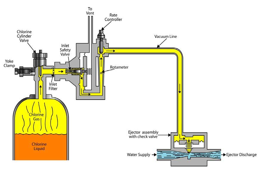
Disinfection Chlorination ©2017, Texas A&M Engineering Extens ion Service. All rights reserved. PM 6 - 25
Figure 6.4: Gas chlorinator. Source: TEEX.
Minimum Residuals Requirements
The following are minimum disinfection residuals in the distribution system:
•Free chlorine residual - 0.2 mg/L
•Chloramine (measured as total residual) - 0.5 mg/L
Ninety-five percent of all distribution residual readings must be above the minimum for every consecutive two-month period. Chlorine residuals are lowest at distribution points farthest from chlorination points.
Maximum Residual Requirements
All community and non-transient, non-community water systems must not exceed a maximum free chlorine or chloramine residual of 4 mg/L based on the running annual average of all distribution samples. Limiting residuals reduces disinfection byproducts such as trihalomethanes and haloacetic acids. These byproducts, consumed over a long time period, may cause cancer.
The maximum contaminant level (MCL) for THMs is 0.080 mg/L, and the MCL for HAA5 is 0.060 mg/L.
Testing for Chlorine Residual
DPD (N,N-diethyl-p-phenylene-diamine) measures the chlorine residual in water in mg/L. The DPD and chlorine reaction turns the water a pink to red color. The DPD and chlorine reaction can be measured with a pocket colorimeter, benchtop spectrophotometer, manual titration, or automated amperometric titration. A review of the various methods is included in AppendixD.
Chlorine Reactions in Water
When chlorine gas (Cl2) is added to water, two acids are formed: hypochlorous (HOCl) and hydrochloric acid (HCl). The disinfectant is HOCl, and since it is an acid, pH affects the degree of disinfection. When using a free chlorine residual, a chlorine odor and or taste can occur. When chlorine demand has been satisfied, the chlorine will combine with organic compounds or ammonia in the water to form chlororganics and chloramines, which can also cause taste and odor. The addition of more chlorine will push the residual beyond breakpoint until only a free available residual remains. The taste and odor should dissipate.
Disinfection Chlorination ©2017, Texas A&M Engineering Extens ion Service. All rights reserved. PM 6 - 26
Inorganic and organic matter react with chlorine, reducing or destroying its disinfecting power. These substances are called reducing agents, or demand. Ammonia, iron, manganese, hydrogen sulfide, bacteria, and organic compounds are some chlorine-reducing agents.
Chlorine Demand Curve (Breakpoint Chlorination)
(1) Chlorine satisfies inorganic demand, forming no residual.
(2-3) Chlorine reacts with organics and ammonia. Chlorine and ammonia produce chloramines, disinfectants weaker than free chlorine, but less reactive and longer lasting. They can cause taste and odor. Chloramine residual increases, then decreases as chlorine concentration increases in the chloramines.
(4) After all reactions, any chlorine added will be free residual (Figure6.5).
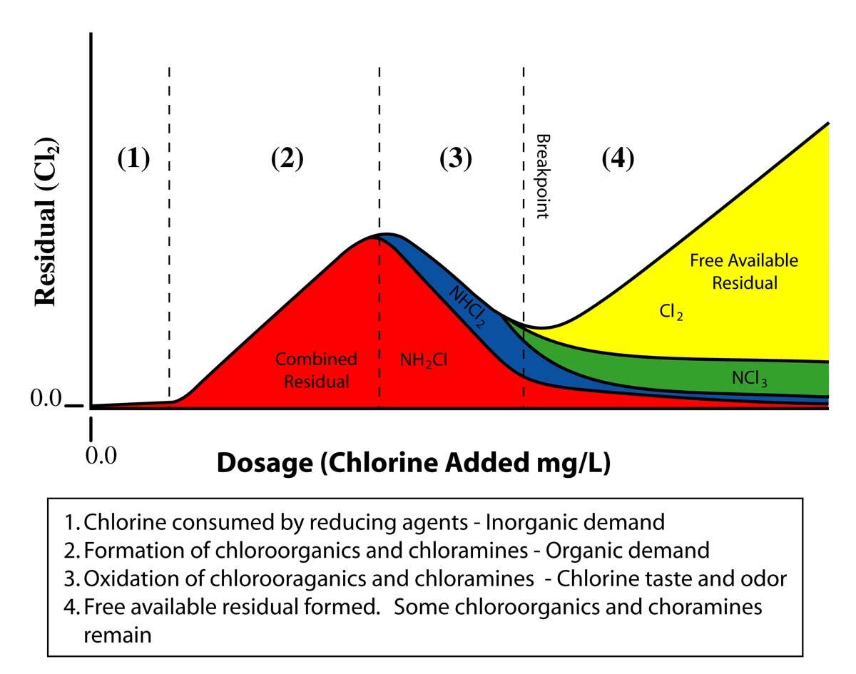
Disinfection Chlorination ©2017, Texas A&M Engineering Extens ion Service. All rights reserved. PM 6 - 27
Figure 6.5: Chlorine demand curve. Source: TEEX.
Formation of Chloramine
Chlorine reacts with ammonia to form chloramine. Unfortunately for the operator, there are three chloramine compounds that can be formed. Monochloramine (NH2Cl) is the desired disinfectant and is formed with Cl:N feed rates of 5:1 or less. This occurs in quadrant 2 of the chart (Figure6.5). In quadrant 3 of the chart, chlorine is overfed and Dichloramine (NHCl2) forms. When this occurs at Cl:N feed rates of 5:1 to 7:1, disinfection is compromised, and the finished water will have a nasty chlorine taste. An even higher Cl:N feed rate of 7:1 to 8:1 will form Trichloramine (NHCl3), which adds a foul odor to the finished water.
Operators, in an effort to feed only monochloramine, will sometimes feed a small amount of free ammonia, which chemically is correct. If a trace of free ammonia is present, only monochloramine can form. However, free ammonia provides nutrition to the biofilm in the distribution system, which can further degrade the disinfectant residual. Bacteria that exist in the biofilm will use free ammonia as food, a process known as nitrification. Nitrification converts the ammonia into nitrite and nitrate. This problem becomes more severe when temperatures are warm and usage low.
Nitrification is minimized by using the following procedures:
•Optimize the chloramination process. Closely monitor free and total chlorine, monochloramine and free ammonia at the treatment plant and in the distribution system.
•Reduce water age in the system by flushing and cycling all water storage tanks.
•Conduct routine system maintenance by high-flow flushing (unidirectional flushing) or pigging.
•Replace aging pipes.
Chlorine Safety
Chlorine is extremely toxic and highly irritating to the nose and throat, causing severe coughing and tissue damage. Heavy exposure can be fatal!
A Self-Contained Breathing Apparatus (SCBA) must be readily available, but stored away from the chlorinator room and inspected regularly.
Chlorinator Rooms and Equipment
Disinfection equipment must have a capacity of at least 50% greater than the highest expected dosage at any time.
Disinfection Chlorination ©2017, Texas A&M Engineering Extens ion Service. All rights reserved. PM 6 - 28
Housing must be aboveground, and chlorinator equipment and chlorine containers must be in separate buildings or separate rooms from mechanical or electrical equipment.
Because chlorine gas is heavier than air, it flows toward the floor. Chlorinator rooms must have high-level and floor-level screened vents. Rooms containing more than one open 150-lb. cylinder must have forced air ventilation, including vents and a fan. The fan switch must be outside the room (Figure6.6 and Figure6.7).
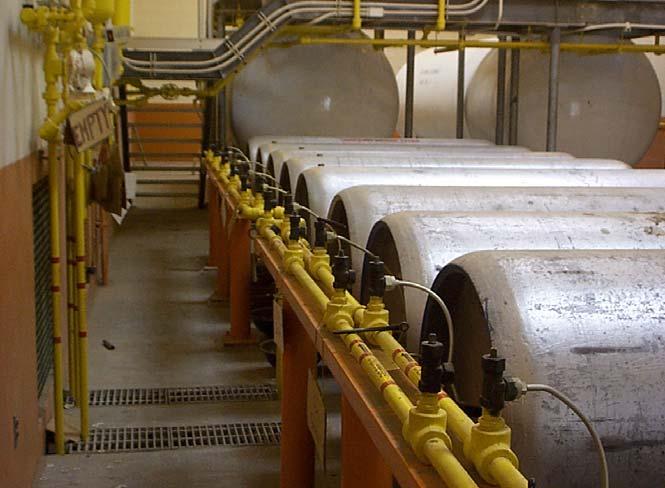
Disinfection Chlorination ©2017, Texas A&M Engineering Extens ion Service. All rights reserved. PM 6 - 29
Figure 6.6: Chlorine one-ton containers.
Source: TEEX.
Store chlorine containers between 50° F and 140° F. Heat-sensitive pressure relief plugs in containers melt at about 160° F.
Scales must be provided to determine the amount of disinfectant used and the amount remaining daily.
Hypochlorination solution containers and pumps must be housed and locked to protect against adverse weather and vandalism. The solution container must be covered to prevent contamination.
Chemical Risk Management
EPA requires any private, municipal, or industrial entity storing or using 2,500 lbs. or more of chlorine to have a chemical risk management program. The TCEQ requires that evacuation procedures be established where one-ton or more chlorine or ammonia container is within 1/4 mile of a residential or other high-density development.
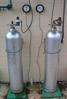
Chlorine Leaks
Detect chlorine leaks by holding an open bottle of 10% ammonium hydroxide (ammonia and water) under the suspected point. If chlorine is escaping, ammonium chloride will appear as a white smoke. The Chlorine Institute does not recommend household ammonia. Repair leaks as soon as possible!
©2017, Texas A&M Engineering Extens ion Service. All rights reserved. PM 6 - 30
Disinfection Chlorination
Figure 6.7: 150-lb. cylinders. Source: TEEX.
Before entering a room that contains chlorine gas, the following are suggested:
•Be trained and prepared.
•Wear a fresh air supply.
•Have standby help.
•Have repair equipment.
•Wear a safety harness and lifeline.
In case of leaks, the best source of help is the supplier!
Tightening the packing gland or closing the cylinder valve stops leaks around the container valve stem. If necessary, apply the Chlorine Institute repair kit “A” for 150-pound cylinders or kit “B” for ton containers, then call the supplier!
•If a leak is extensive, potentially exposed persons should move upwind or to the crosswind.
•If a leak develops while transporting containers, keep the vehicle moving until open country is reached.
•A leaking container must not be immersed in a body of water; the leak will get worse and the container may float, allowing gas to leak at the surface.
The operator is at the greatest risk when changing out cylinders or containers. Before breaking connections loose, make sure the chlorine valve is closed and the gas is bled out of the system. Break connections loose slowly. Once the cylinder or container is changed out and connections are tightened, briefly pressurize the system and turn the gas off. Detect any leaks by holding an open bottle of 10% ammonium hydroxide under each connection. If there is a leak, a white smoke will form as the ammonia combines with the leaking chlorine gas. Repair the leak and then retest using the ammonia bottle. When no leaks are detected, open the chlorine valve one-quarter turn and place the system into service. The valve wrench should remain on the open valve.
First Aid
Chlorine irritates the eyes, nose, and throat. High concentrations cause vomiting and labored breathing that can progress to suffocation.
There should be first aid equipment and trained personnel to aid anyone contacting chlorine gas:
•Take patient to fresh, warm air. Allow them to sit or lie down with head and trunk elevated.
Disinfection Chlorination ©2017, Texas A&M Engineering Extens ion Service. All rights reserved. PM 6 - 31
•Call medical help.
•Wash skin or clothing in a safety shower or with a garden hose.
•Flush eyes with cool water at least 15 minutes.
•If the victim is not choking, give coffee, tea, milk, or peppermint candy to relieve throat irritation, but do not give alcohol.
•If necessary, give artificial respiration or use a mechanical respirator if the attendant is trained.
•If you encounter chlorine, keep your mouth closed, avoid deep breathing, keep your head high, and quickly leave the area.
Alternative Disinfectants
Chlorine Dioxide
Chlorine dioxide is a yellow-green gas with a chlorine-like odor. It is a very powerful oxidizer. It is effective against taste, odor, color, iron, manganese, or organics, and equal to or better than chlorine as a biocide. However, like chlorine, it is not effective against cryptosporidium or giardia at normal doses.
Chlorine dioxide does not produce THMs or HAAs, but does produce chlorites and chlorates, which are thought to be a health risk by EPA. The TCEQ allows no more than 0.8 mg/L of chlorine dioxide in the distribution system. At such low limits, chlorine dioxide is applicable for pretreatment, not as a final disinfectant.
Because it cannot be compressed or stored, chlorine dioxide must be generated on site, at higher cost than purchasing chlorine. Chlorine dioxide residuals are not as stable as chlorine residuals, and are more difficult to measure.
Ozone
Ozone, a faintly blue gas, is a concentrated form of oxygen, made of three oxygen atoms instead of two. Because the third oxygen atom is very unstable, ozone is the most powerful chemical oxidizer and the most powerful chemical biocide. It is the most effective chemical against cryptosporidium or giardia.
Ozone is superior to any other chemical in oxidizing taste, odor, color, iron, manganese, or organics in water. Because of its instability, it must be produced on site (Figure6.8). Passing an electrical current through air or oxygen generates it. This energy intensive process makes ozone the most expensive chemical disinfectant.
Disinfection Chlorination ©2017, Texas A&M Engineering Extens ion Service. All rights reserved. PM 6 - 32
Ozone does not produce THMs or HAAs, but can produce aldehydes, an alcohol without a hydrogen atom and bromates, a form of oxidized bromine. These byproducts are considered health risks by EPA.
The TCEQ does not approve ozone as a final disinfectant; not only because of byproducts, but also because it quickly decomposes, leaving no residual.
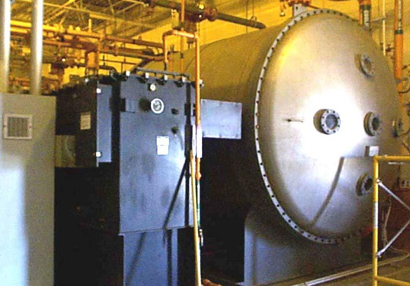
Ultraviolet Light
Ultraviolet light (UV), in certain wavelengths, is effective as a biocide. Low doses kill bacteria, viruses, and cryptosporidium. Advanced designs are having some success against giardia (Figure6.9). UV produces no disinfection byproducts, but turbidity reduces effectiveness and systems are expensive to operate. A critical disadvantage is that UV produces no residuals.
Disinfection Chlorination ©2017, Texas A&M Engineering Extens ion Service. All rights reserved. PM 6 - 33
Figure 6.8: Ozone generator. Source: TEEX.
Summary
The use of chlorine is an acceptable method of disinfection of drinking water. Once this process is completed, the distribution system provides potable water to the public.
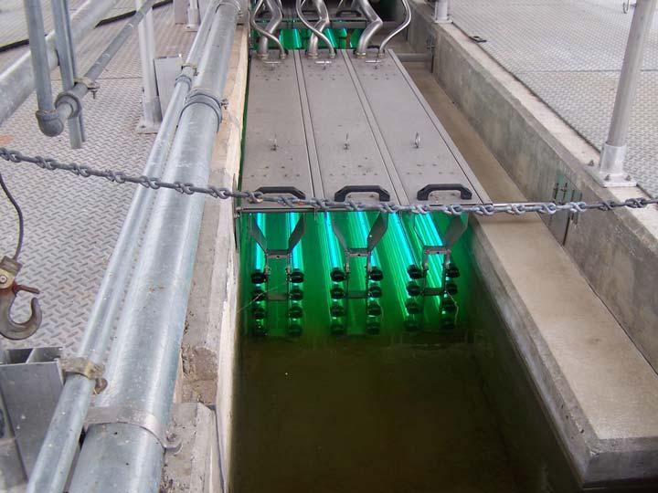
Disinfection Summary ©2017, Texas A&M Engineering Extens ion Service. All rights reserved. PM 6 - 34
Figure 6.9: Ozone generator. Source: TEEX.
Module 6 Review Questions
1.Disinfection destroys disease-causing microorganisms called pathogens.
a.true
b.false
2.Disinfection destroys pathogens without sterilizing the water.
a.true
b.false
3.Waterborne pathogens live and grow in the intestines of infected people.
a.true
b.false
4.Infected fecal matter entering a water supply transmits pathogens to healthy people.
a.true
b.false
5.Some diseases transmitted by unsafe water include typhoid, dysentery, cholera, measles, polio, and cryptosporidiosis.
a.true
b.false
6.Each water sample is tested for all waterborne diseases.
a.true
b.false
7.Water samples are tested for microorganisms that indicate fecal contamination.
a.true
b.false
8.The total coliform group of viruses are the indicators of fecal contamination.
a.true
b.false
Disinfection Module 6 Review Questions ©2017, Texas A&M Engineering Extens ion Service. All rights reserved. PM 6 - 35
9.Fecal coliform live in the intestines of humans and warm-blooded animals.
a.true
b.false
10.The presence of fecal coliform in a water sample indicates intestinal waste is in the sample, but there is no risk of disease.
a.true
b.false
11.The number of water taps served by the system determines the minimum number of bacteriological samples.
a.true
b.false
12.The purpose of the sample siting plan is to assure bacteriological samples are taken from vacant houses.
a.true
b.false
13.Sodium thiosulfate is put into bacteriological sample bottles to sterilize the water.
a.true
b.false
14.Before taking a bacteriological sample, you should flush the service line.
a.true
b.false
15.The sample bottle should be completely filled with sample water.
a.true
b.false
16.The monthly bacteriological sample should be marked “construction.”
a.true
b.false
Disinfection Module 6 Review Questions ©2017, Texas A&M Engineering Extens ion Service. All rights reserved. PM 6 - 36
17.Get samples to the lab within 36 hours or they are rejected.
a.true
b.false
18.It is possible to have positive samples removed from your record.
a.true
b.false
19.It is an acute public health risk if a positive fecal coliform repeat sample or a positive total coliform repeat sample follows a positive fecal coliform routine sample.
a.true
b.false
20.Acute violations require public notification within 72 hours by radio and television using the words “Minor Health Concern.”
a.true
b.false
21.In the event of low distribution pressure (below 20 psi), water outages, repeated unacceptable microbiological samples, or failure to maintain adequate chlorine residuals, special precautions must be instituted by the water system.
a.true
b.false
22.In Texas, all public water systems are required to have ________ facilities.
a.ozonation
b.chlorination
c.softening
d.trihalomethane
23.Chlorination is the most important process in the production of ________ water.
a.public
b.private
c.potable
d.political
Disinfection Module 6 Review Questions ©2017, Texas A&M Engineering Extens ion Service. All rights reserved. PM 6 - 37
24.Besides disinfection, chlorine is used for taste and odor control and ________.
a.oxidation of iron and manganese
b.oxidation of hydrogen sulfide
c.disinfection of repairs
d.all listed
25.Sodium hypochlorite is liquid ________.
a.bleach
b.sodium
c.chlorine
d.hydroxide
26.Bleach used in public water systems must be ________ approved.
a.AWWA
b.TEEX
c.OSHA
d.NSF
27.Calcium hypochlorite is made by reacting chlorine with ________.
a.sodium
b.lime
c.bleach
d.salt
28.Calcium hypochlorite will cause explosions or fires if it contacts ________ material.
a.organic
b.inorganic
c.suspended
d.dissolved
Disinfection Module 6 Review Questions ©2017, Texas A&M Engineering Extens ion Service. All rights reserved. PM 6 - 38
29.At room temperature, chlorine gas is greenish-yellow, has a pungent odor, is ________ times heavier than air.
a.2
30.The maximum sustained gas withdrawal rate from 150-lb. cylinders (vacuum transmission) is ________ lb(s)./day per degree F.
31.Disinfection capacity for drinking water must be ________% greater than the highest expected dosage.
32.Small water systems often use ________ to disinfect their water supply.
a.hydrochlorinators
b.hypochlorinators
c.hyperchlorinators
d.hydrachlorinators
33.Hypochlorinators consist of a mixing tank, water, ________ hypochlorite, or ________ hypochlorite and a chemical pump.
a.sodium/calcium
b.salt/lime
c.hydrogen/oxygen
d.green/yellow
Disinfection Module 6 Review Questions ©2017, Texas A&M Engineering Extens ion Service. All rights reserved. PM 6 - 39
b.1 1/2 c.2 1/2 d.3
a.4 b.3 c.2 d.1
a.30 b.40 c.50 d.60
34.Gas chlorinators use a rotameter to meter chlorine in ________ or grams/hr.
a.lbs./minute
b.lbs./hour
c.lbs./day
d.gal./minute
35.Dosage is the amount of chemical applied, demand is the amount of chemical used up, ________ is the amount of chemical remaining after reacting with demand.
a.breakpoint
b.chloramines
c.residual
d.combined
36.Minimum chlorine residuals of ________ (free) and ________ (combined) are required in the far reaches of the distribution system.
a.0.5/0.2
b.5/2
c.2/5
d.0.2/0.5
37.The DPD and chlorine reaction turns the water a ________ color.
a.green to blue
b.pink to red
c.yellow to red
d.red to brown
38.Chlorine and water make two acids: hydrochloric (HCl) and ________ (HOCl).
a.hypochlorous
b.hypochloric
c.hyperclorous
d.hydrachloric
Disinfection Module 6 Review Questions ©2017, Texas A&M Engineering Extens ion Service. All rights reserved. PM 6 - 40
39.A Self-Contained Breathing Apparatus (________) must be readily available.
a.SCUBA
b.SCBA
c.SCAB
d.CABS
40.Chlorinator rooms must have ________-level and ________-level screened vents.
a.window/ceiling
b.door/floor
c.high/floor
d.low/window
41.In chlorinator rooms, ________ must be provided to determine the amount of disinfectant used and the amount remaining daily.
a.turbidimeters
b.pH meters
c.color comparators
d.scales
42.EPA requires any private, municipal, or industrial entity storing or using ________ pounds or more chlorine to have a chemical risk management program.
43.Heat-sensitive pressure relief plugs in chlorine containers melt at about ________ degrees F.
Disinfection Module 6 Review Questions ©2017, Texas A&M Engineering Extens ion Service. All rights reserved. PM 6 - 41
a.2,000 b.2,500 c.3,000 d.3,500
a.140 b.150 c.160 d.170
44.Hold an open bottle of ________ ammonium hydroxide under a suspected chlorine leak.
a.10%
b.20%
c.30%
d.40%
45.In case of leaks, the best source of help is the ________.
a.TCEQ
b.supplier
c.EPA
d.fire department
46.After contacting chlorine gas, wash in a safety shower or with ________.
a.compressed air
b.an ammonia solution
c.a garden hose
d.tanning oil
Disinfection Module 6 Review Questions ©2017, Texas A&M Engineering Extens ion Service. All rights reserved. PM 6 - 42
Distribution
Terminal Objective
Upon the successful completion of this module, the participant will be able to describe the common methods of water delivery to the public following water treatment.
Enabling Objectives
1.Discuss the different types of storage.
2.List the major components of the distribution system.
3.Explain the different aspects of pump usage for distribution.
4.Discuss the use of motors in distribution system pumps.
©2017, Texas A&M Engineering Extens ion Service. All rights reserved.
Module
Distribution ©2017, Texas A&M Engineering Extens ion Service. All rights reserved. PM 7 - 2
Introduction
Storage facilities equalize demand on the water supply. When demand for water is low, storage will be filling. During peak water demand, storage will begin to empty. Storage:
•allows uniform pumping rates;
•supplies water for firefighting; and
•provides time for disinfection.
Storage Reservoirs
Types of Storage
Ground Storage
Ground storage is generally constructed of reinforced concrete or steel, and placed after production and ahead of distribution (Figure7.1).
Ground storage at a surface water treatment plant receiving the treated water is called a clear well.
The TCEQ requires all storage tanks to have screened vents, locked hatches, a dust-proof cover, overflows with hinged flaps, and entry ports. Screens must be made of corrosion-resistant material 16-mesh or finer. Overflow covers must have no gap greater than 1/16 inch. The rim of the entry port must extend at least four inches above the tank and have a lid with a two-inch overlap to prevent rain from entering. If ground storage is the only storage, capacity must be 200 gallons per connection. Otherwise, total storage capacity (elevated storage included) must be 200 gallons per connection.
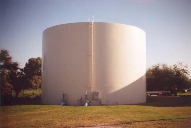
Distribution Introduction ©2017, Texas A&M Engineering Extens ion Service. All rights reserved. PM 7 - 3
Figure 7.1: Ground storage. Source: TEEX.
If a 30-inch diameter access opening is not provided in a storage tank, the primary roof access must not be less than 30 inches. An existing tank without a 30-inch access opening must be provided with one when major maintenance is performed on the tank.
Storage tanks must be painted, disinfected, and maintained according to AWWA standards. No paint, coating, or wax containing lead is allowed. Coatings for contact with potable water must be approved by EPA, National Sanitation Foundation (NSF), or the U.S. Food and Drug Administration.
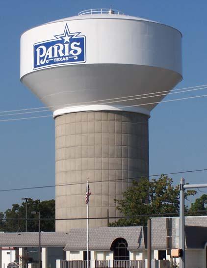
Elevated Storage
An elevated storage tank is usually constructed with steel and supported aboveground on a tower (Figure7.2). Pressure is maintained by the height of the water column. The taller the water column, the more weight and the more pressure. Each foot of a water column produces 0.433 psi.
The TCEQ considers elevated storage as water stored at least 80 feet above the highest service connection. Such elevation provides pressure that meets the state minimum normal operating pressure of 35 psi.
Elevated storage is required for systems with more than 2,500 connections and capacity must be 100 gallons per connection. Elevated storage must meet the same general design criteria as ground storage.
Distribution Storage Reservoirs ©2017, Texas A&M Engineering Extens ion Service. All rights reserved. PM 7 - 4
Figure 7.2: Elevated storage. Source: TEEX.
Standpipes
A standpipe is a tank resting on the ground that is greater in height than diameter. A standpipe is considered ground storage unless it exceeds 80 feet above the highest service connection (Figure7.3).
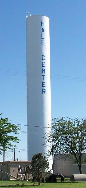
Standpipes are usually built on elevated ground where an 80-foot tower is unnecessary.
Standpipes must meet the same general design criteria as elevated storage.
Pressure Tanks
Pressure tanks (hydropneumatic tanks) are cylindrical and horizontal to the ground. Air mechanically compressed against the water surface provides pressure (Figure7.4).
Distribution Storage Reservoirs ©2017, Texas A&M Engineering Extens ion Service. All rights reserved. PM 7 - 5
Figure 7.3: Standpipe storage. Source: TEEX.
Pressure tanks are used in mobile home parks, subdivisions, resorts, and some rural water systems to maintain pressure in distribution. In some cases, pressure tanks can substitute for elevated storage.
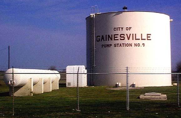
A water system without ground storage (less than 50 connections) must have a pressure tank capacity of 50 gallons per connection. A system with ground storage is allowed pressure tank capacity of 20 gallons per connection, or elevated storage.
Storage Maintenance Annual Inspections Required
The exterior and interior of ground, elevated, standpipe, and pressure tanks must be inspected yearly by water system personnel or a contracted service. Inspection results must be documented and kept at least five years.
Inspections determine if the tanks are watertight, are not accumulating interior sand or chemicals, and have screened vents, locked roof hatches, and flap valves that properly seal.
The exterior and interior coating must be inspected for corrosion protection. The interior coating must meet AWWA specifications.
Protecting Tanks Against Corrosion
Besides coatings, additional means of corrosion protection are:
•cathodic protection,
•water conditioning, and
•galvanizing (not for elevated tanks).
Distribution Storage Reservoirs ©2017, Texas A&M Engineering Extens ion Service. All rights reserved. PM 7 - 6
Figure 7.4: Pressure tank. Source: TEEX.
Cathodic protection is an electrochemical method for preventing corrosion of the interior of metal tanks. Direct current travels through strips or rods of aluminum or other conductive metal. The strips/rods are suspended in the tank, then through the water, thus electroplating the walls below the waterline. Metal above the waterline is not protected.
Water conditioning involves adding chemicals to make the water less corrosive or applying a protective coating on the tank walls.
Ownership Signs
Ownership signs must include the utility name and emergency phone number at each production, treatment, or storage site.
Grounds and Landscaping
The TCEQ requires utilities to have a program to facilitate cleanliness and improve the appearance of plant sites.
The grounds must be sloped away from the tank or tower to prevent collection of surface water that can cause contamination and weaken foundations.
Chain link fence material must be flush with the ground, without a gap.
Sanitary Protection
The state requires stored water to have a disinfectant residual.
If a tank is wholly or partially underground, it cannot be located near potential contaminants such as sewer lines, septic tank drain fields, animal feed lots, or areas prone to flooding.
Cracks and leaks must be repaired as soon as possible.
Sunlight (causes algae growth), dust, birds, insects, and rain are contaminants and must be prevented from entering the tank.
Storage tanks must be disinfected after construction or maintenance. After a tank is disinfected, a sample must be collected for bacteriological analysis. If the sample is negative, the tank may be placed into service. If the sample is positive, more samples must be taken until two consecutive samples are negative. If samples continue to be positive, repeat the disinfection process.
Distribution Storage Reservoirs ©2017, Texas A&M Engineering Extens ion Service. All rights reserved. PM 7 - 7
The Distribution System
The distribution system consists of water mains, service lines, meters, valves, hydrants, and pressure booster pump stations. The system must meet standards for water quality, quantity of water, pressure, and fire protection.
Critical safeguards of a distribution system include a minimum chlorine residual, adequate pressure, monthly bacteriological sampling, and cross-connection control programs.
The TCEQ requires distribution system pressure to never fall below 20 psi, even during emergencies. TCEQ rules and regulations for operating a water distribution are found in 30 TAC Chapter 290.44. These regulations can be downloaded from the TCEQ website in either MS Word or PDF format. Chapter 290.44(d) contains the TCEQ rules for distribution system pressure. Note that distribution system pressure should never fall below 20 psi, even during emergencies. Under normal operating conditions, the distribution pressure must be at least 35 psi. Adequate pressure prevents contaminated water from being drawn into and throughout the system.
Components of the Distribution System
Material used in water line construction must meet the AWWA specifications and should not affect the taste, odor, or quality of the water.
Pipe Material
Pipe can be ductile iron, cast iron, steel, asbestoscement, concrete, Polyvinyl Chloride (PVC), or copper. Asbestos-cement pipe is not allowed in Texas for new construction in potable water systems. Plastic pipe must be NSF (National Sanitation Foundation) approved and have an ASTM (American Society for Testing and Material) pressure rating of at least 150 psi or a standard dimension ratio of 26. No pipe used for any purpose other than drinking water is acceptable in a public supply. Select pipe on the basis of strength, carrying capacity, durability, ease of installation, availability, soil conditions, and cost.
Lead ban: According to the TCEQ and EPA, pipe and fittings containing more than 8.0% lead, or solders and flux containing more than 0.2% lead, are prohibited in a public water supply or in plumbing connected to a public water supply.
Distribution The Distribution System ©2017, Texas A&M Engineering Extens ion Service. All rights reserved. PM 7 - 8
However, the Reduction of Lead in Drinking Water Act was enacted on January 4, 2011 to amend Section 1417 of the Safe Drinking Water Act (SDWA or Act) respecting the use and introduction into commerce of lead pipes, plumbing fittings or fixtures, solder and flux. The Act established a prospective effective date of January 4, 2014, which provided a three-year time frame for affected parties to transition to the new requirements.
The new definition of “lead free” will be:
(A) not containing more than 0.2 percent lead when used with respect to solder and flux; and
(B) not more than a weighted average of 0.25 percent lead when used with respect to the wetted surfaces of pipes, pipe fittings, plumbing fittings, and fixtures.
Pipe Joints
Pipe joints are either flanged, mechanical, push-on, welded, or threaded. Gasket material should prevent bacterial growth.
Valves
The purpose of water valves is to control water flow. The manner in which a valve accomplishes this task depends on the valve type or classification. A valve classified by function is used for isolation or control.
Isolating valves cut off sections of a system. An isolation valve is designed to prohibit or permit the flow of water. An isolation valve can be either closed or open, and is not generally used to throttle water flow. Most distribution valves are isolation valves.
Classification by design includes slide, rotary, globe, diaphragm, and special valves.
Slide valves include gate, sluice gate, and shear gate valves. Sluice gate and shear gate valves are used for flow control in water treatment plants.
Rotary valves used in the distribution system include butterfly, cone, and ball valves.
Globe valves have a flat or tapered disk of resilient material that lowers onto a seat to stop or restrict flow, giving it a wide range of pressure and flow settings. The typical household faucet is a globe valve.
Distribution The Distribution System ©2017, Texas A&M Engineering Extens ion Service. All rights reserved. PM 7 - 9
Inside a diaphragm valve is a piece of flexible material that is attached to the circumference of the valve body. To regulate or stop the flow of water, the flexible material (diaphragm) is pressed onto the valve seat by an operating stem. When the stem is raised, flow is restored.
There are many valves that do not fit the discussed classifications. These are referred to as special valves. Examples of these categories are the swing check valve, the silent check valve, and the air/vacuum relief valve. The most commonly used is the gate valve.
A control valve regulates pressure, volume, or flow direction. Flow pressure and volume may be regulated by throttling the valve. Control valves include globe, altitude, check valves, diaphragm, and rotary valves. One way to control flow direction is by using a swinging flap found in a check valve. Check valves are installed on the discharge side of pumps to prevent backflow when the pump is off. A control valve that is set or adjusted by differential pressure is called an automatic control valve. Pressure-regulating valves are often globe valves that reduce water pressure by restricting the flow through it.
Fire Hydrants
Other than firefighting, an important use of hydrants is flushing. Flushing can assist in solving problems such as taste and odor, red water, dirty water, or bad samples. Hydrants can be used to bleed air from mains after construction or repair (Figure7.5).
Distribution The Distribution System ©2017, Texas A&M Engineering Extens ion Service. All rights reserved. PM 7 - 10
Meters
Meters measure the flow of water into and out of treatment plants, into the distribution system, and to customers. Propeller, compound, and magnetic meters are common designs. The positive displacement meter is the most common design for residential use (Figure7.6). It is very accurate at low flows and cannot over register from external influence or the internal wearing of the meter components.
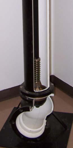
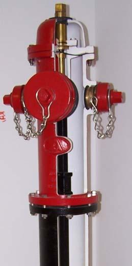
Distribution The Distribution System ©2017, Texas A&M Engineering Extens ion Service. All rights reserved. PM 7 - 11
Figure 7.5: Fire hydrant cutaway. Source: TEEX.
Operating Nut Bonnet or Cap Barrel
Pumper Nozzle
Hose Nozzle
Traffic Coupling
Main Valve
Shoe
Water flowing through the meter chamber (A) causes a disc (B) to nutate or wobble. This motion, in turn, results in the rotation of a spindle (C) and drive magnet (D). Rotation is transmitted through the wall of the meter to a second magnet (E) that operates the register.
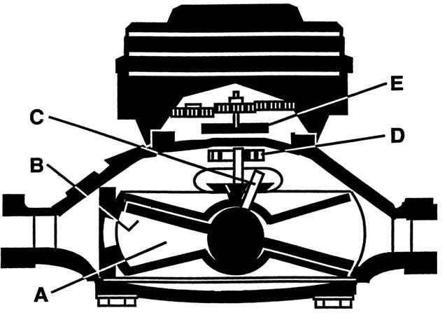
Pipe Installation
Main Installation
Water mains must be no closer than nine feet, in all directions, from sewers or manholes. Distances are measured from the outside surface of each pipe. Parallel water and sewer lines must be laid in separate ditches. When the nine-foot separation cannot be achieved, refer to TCEQ regulation 30 TAC 290.44(e)(5).
The piece of pipe material cut from a main when a tap is made is called a coupon.
Trenches for laying 6-inch or larger pipe must be a minimum of 18 inches wide and 12 inches wider than the pipe diameter. Main depth depends on frost lines, surface load, and obstructions. In Texas, 30 to 60 inches is the rule, but the top of the pipe must have at least 24 inches of cover.
Distribution The Distribution System ©2017, Texas A&M Engineering Extens ion Service. All rights reserved. PM 7 - 12
Figure 7.6: Positive displacement, nutating disk water meter. Source:BadgerMeter,Inc.
Service Line Installation
The valve that connects the service line to the main is called the corporation stop. It is buried when the hole is backfilled and cannot be operated from the ground surface. The valve that connects the service line to the meter is called a curb stop or meter stop. It can be operated from the meter box.
Trench Safety
Do not work in a ditch five feet or deeper unless it is protected from cave-ins. The life you save may be your own!

Cave-ins are likely when:
•the soil is wet,
•spoil banks are too close to the trench, or
•traffic or machinery vibrations loosen the soil. Use of timber, plywood, or commercial devices to support an excavation is known as shoring (Figure7.7).
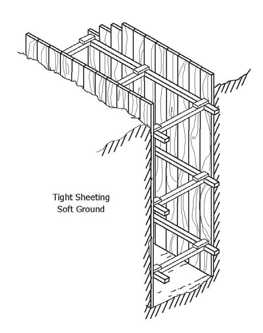
Distribution The Distribution System ©2017, Texas A&M Engineering Extens ion Service. All rights reserved. PM 7 - 13
Figure 7.7: Trench shoring. Source: TEEX.
If shoring is used, it is installed from the top down and removed from the bottom up. Shoring should be inspected daily by a competent person. If problems arise, such as subsidence or soil cracks, stop work immediately and correct the problem.
Shoring is not necessary if the trench walls are sloped to the maximum allowable slope, which is the degree of slope that overcomes collapsing pressure. The slope is determined by soil conditions.
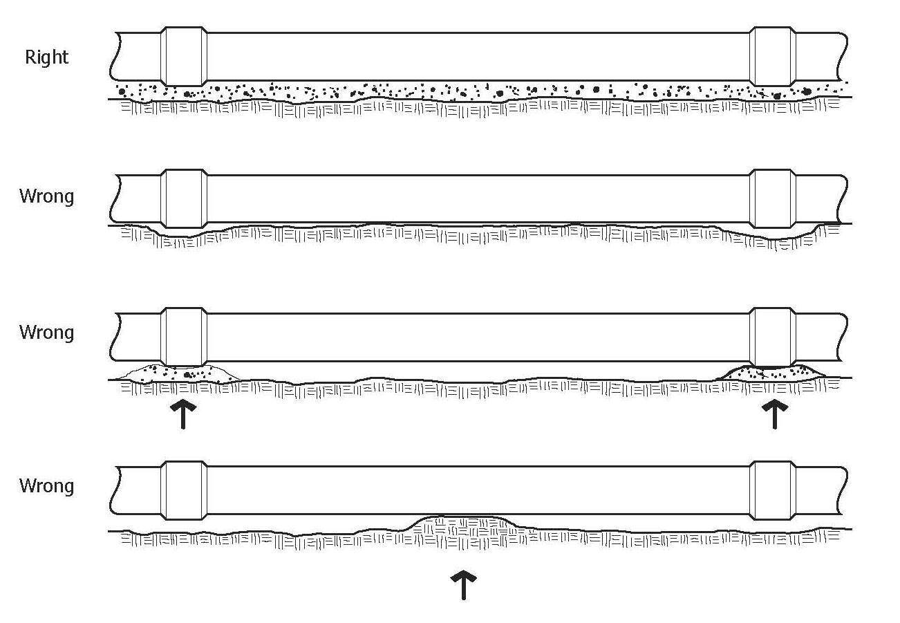
Trench boxes may be used in place of shoring, but workers must stay in the box to be protected. Place spoil banks at least two feet from the excavation.
Pipe Bedding
Pipe must be bedded with a minimum of four inches, or 1/4 of the pipe diameter, of tamped sand or gravel (Figure7.8). When the pipe is in place, backfill the trench carefully.
Pipe Bracing
Wherever the line changes direction, the bend must be braced or blocked against internal thrust. At 60 psi, there is almost 1,700 lbs. of thrust against a closed six-inch valve.
Distribution The Distribution System ©2017, Texas A&M Engineering Extens ion Service. All rights reserved. PM 7 - 14
Figure 7.8:
Sanitation
Trenches should be kept as clean and dry as possible. Ditch water should not be allowed to enter the pipe. Installation crew must never use the trench as a latrine.
To maintain sanitary conditions, swab pipe with a hypochlorite solution as it is laid in the trench. Never leave installed pipe with an open end. Cap it with a watertight plug.
Disinfection
AWWA standard C651-92 provides three methods of chlorination for water mains: tablet, continuous, and “slug.” The chlorine dose and minimum contact time for each AWWA method is summarized in the table below (Table7.1). Recommendations for disinfection of small sections of mains under emergency repair are also included in the table below. Before any disinfection method is utilized, valves must be positioned so that the highly chlorinated water in the main being treated does not flow into water mains in active service. When it is necessary to return repaired mains to service as rapidly as possible, doses may be increased to 500 mg/L and the contact time reduced to 1/2 hour.
After the new or repaired line is disinfected, flush the line to discharge the excess chlorinated water.
Distribution The Distribution System ©2017, Texas A&M Engineering Extens ion Service. All rights reserved. PM 7 - 15
Chlorination Methods for Disinfection of Water Mains Chlorination Method Used Initial Chlorine Dosage (mg/L) Minimum Contact Time (Hours) Minimum Chlorine Residual (mg/L) Nonemergency Procedures Tablet 25 24 10 Continuous252410 Slug 100 3 50 Emergency Procedures Premixed solution or Hydrochlorite injection 300 0.25 100 Swabbing10,000 (1% Solution)N/ASwab thoroughly the interior of pipes and fittings used in repairs
Table 7.1: AWWA Standard C651-92 Chlorination Methods
Do not place a new main into service until a bacteriological sample is analyzed and shows negative results. One sample is required for each 1,000 feet of completed main.
Maintenance of Distribution Systems
Flushing
Dead-end mains must be flushed once a month. Flushing reduces slime and scale buildup, reduces red water complaints, brings fresh chlorinated water to contaminated areas, and reduces chlorine-reducing materials from the distribution system.
Flush carefully! Pressure surges created by rapid flow changes, such as closing a hydrant valve too quickly, cause water hammer and possible extensive damage to mains.
Scale
Tuberculation is a buildup of oxidized iron, calcium carbonate, or other chemicals in mains. High-pressure water, pigs or swabs, and chemicals are methods of removing scale.
Corrosion
Corrosion is the dissolving of metal. Corrosion will damage pipe and storage tanks and affects water quality. Corrosive water may become discolored with rust, resulting in an unpleasant taste. Corrosive water may contain harmful amounts of lead, copper, or other metals.
Factors that make water more corrosive are as follows:
•Low pH
•Dissolved oxygen and carbon dioxide
•Dissolved salts
•Free chlorine
•Low hardness
•High velocity
•High temperature
•Low alkalinity
•Sulfate-reducing bacteria
If the water is red, but not corrosive, the cause could be iron bacteria.
Distribution The Distribution System ©2017, Texas A&M Engineering Extens ion Service. All rights reserved. PM 7 - 16
Corrosion is controlled by using pipe with protective linings or coatings, installing anodes in storage tanks, eliminating different metals (galvanic corrosion) in the distribution system, and treating the water with chemicals.
Galvanic corrosion occurs when different metals, such as copper and steel, are connected. Dielectric (nonconducting) unions should be used to separate metals.
Main Repairs
Main breaks are a challenge to any utility. Crews must be supplied with tools, repair materials, maps of the distribution system, pipe location equipment, safety equipment, traffic control devices, and first aid supplies. Backhoes, pumps, and air compressors should be stored at a service center.
When the leak is found:
•excavate below the pipe on both sides, allowing repair materials to be easily set;
•dig one side deeper to form a pump sump; and
•reduce contamination risk by keeping pooled ditch water out of the pipeline.
When possible, repair the leak “hot”—without turning off the valves. Working the leak under pressure has the following advantages:
•Eliminates interrupted service
•Reduces risk of contamination
•Reduces air in the main
•Ensures the repair holds under service
Proper cleanup is important for good public relations. Paving, sidewalks, and driveways must be replaced. Lawns, trees, and shrubs must be restored. Assure that you do not promise residents what is not a utility policy.
Cross-Connection Control
A cross connection is a physical connection between a public water system and:
•another supply of unknown or questionable quality,
•any source that may contain contamination, or
•any water treated to a lesser degree.
Distribution The Distribution System ©2017, Texas A&M Engineering Extens ion Service. All rights reserved. PM 7 - 17
Typical cross connections are bottom connections to stock tanks, lawn-sprinkling systems, faulty pump installations, piping from a private well connected to a house with city water, and pump priming.
Valves or check valves are not safe between a potable and unknown water supply. The air gap is the preferred method to prevent cross connections and is the only method approved by the TCEQ for protection against sewage contamination.
In certain situations, the TCEQ allows backflow prevention devices if properly located, maintained, and inspected.
AWWA standards list and discuss backflow prevention devices such as atmospheric vacuum breakers, double check valve assemblies, and reduced pressure devices.
Emergency Preparedness
In addition to maintenance, be prepared for emergencies. When an emergency situation arises, repair manuals need to be available and spare parts should be on hand.
When severe storms are expected the water utility should:
•alert personnel;
•check communications;
•fill gasoline tanks;
•check emergency equipment;
•fill storage tanks;
•isolate elevated storage;
•restock repair clamps and calcium hypochlorite; and
•review emergency procedures.
Pumps
Centrifugal Pump
This is the most common pump in the water utility industry, although it is not the best pump for every situation (Figure7.9). To be efficient, the centrifugal pump must be designed for a particular job.
©2017, Texas A&M Engineering Extens ion Service. All rights reserved. PM 7 - 18
Distribution Pumps
The centrifugal pump is first primed by filling the volute with water. The volute is the casing enclosing the impeller (Figure7.10).
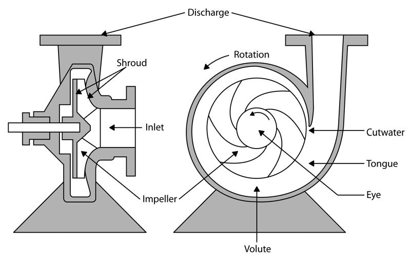
The motor is energized and the impeller spins, throwing water out of the volute by centrifugal force. Water is supplied to the pump by atmospheric pressure (suction lift) or by the weight of the water (suction head).
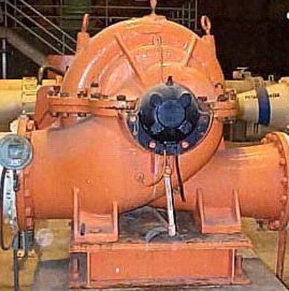
Distribution Pumps ©2017, Texas A&M Engineering Extens ion Service. All rights reserved. PM 7 - 19
Figure 7.9: Centrifugal pump diagram. Source: TEEX.
Figure 7.10: Centrifugal pump. Source: TEEX.
Deep-Well Turbine
A type of centrifugal pump used in water wells is the deep-well turbine. Vertical impellers move the water from one stage to the next. The pumps are either oil or water lubricated. Before starting a water-lubricated pump, the water line must be on.
Centrifugal Pump Selection
Pump selection for a particular system depends on several factors:
•Amount of water to be pumped
•Force (head) the pump works against
•Material to be pumped
•Cost
•Availability
•Pump efficiency
Pump capacity is the output of the pump expressed as gallons per minute (gpm). With a centrifugal pump, the capacity changes as the head (pressure) the pump works against changes. This relationship is inverse. If head pressure goes up, gpm output goes down. When examining the performance of a given pump, its head, output, and efficiency should be calculated.
Pumping Rate
Pumping rate is expressed in gallons per minute or, in very large pumps, million gallons per day.
Head
Head is the force the pump works against. Static head is measured in feet or psi. When there is no flow or pumping, the head is “static.” When there is flow or pumping, the head is “dynamic.”
Suction lift. Vertical distance water is raised from supply to the pump centerline
Suction head. Vertical distance water supply is above the pump centerline
Discharge head. Vertical distance between pump centerline and free discharge
Total static head. Vertical distance between supply and free discharge
Friction head. Force to overcome resistance in pipe and fittings
Distribution Pumps ©2017, Texas A&M Engineering Extens ion Service. All rights reserved. PM 7 - 20
Total dynamic head. Total static head + friction head
Pump Curves
A pump curve assists in selecting a pump (Figure7.11). Three types of curve:
Head capacity curve. Relationship between total head and gallons per minute
Efficiency curve. Relationship between pump efficiency and gallons per minute
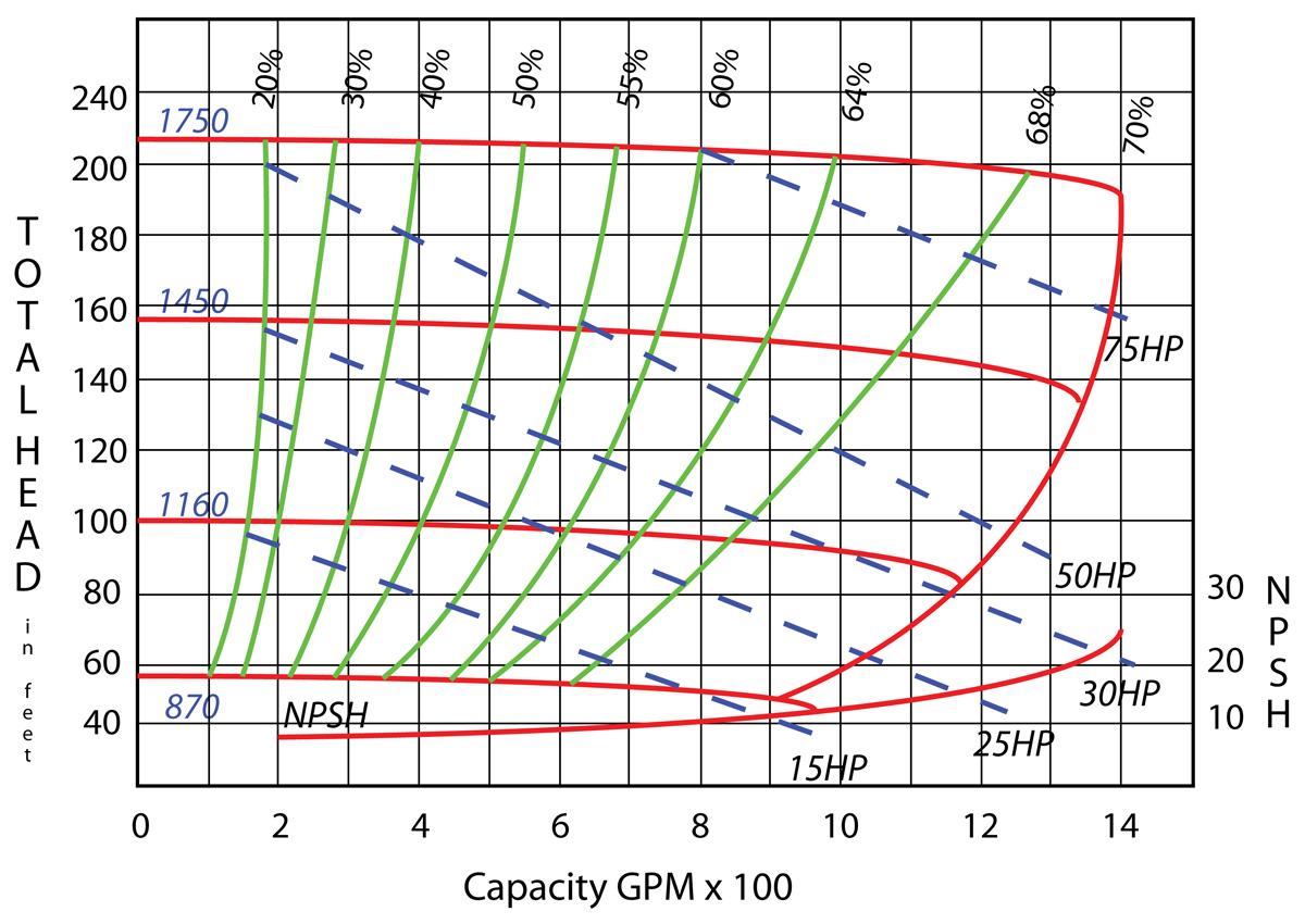
Horsepower curve. Relationship between gallons per minute and horsepower required
Pump Efficiency
Check efficiency periodically by measuring pump performance against manufacturer's specifications.
As head increases, pump capacity and efficiency decrease. Pump efficiency is affected by:
•high suction lift,
Distribution Pumps ©2017, Texas A&M Engineering Extens ion Service. All rights reserved. PM 7 - 21
Figure 7.11: Pump performance curve. Source: TEEX.
•worn impellers,
•clogged impellers, and
•high discharge head.
Pump Operation and Maintenance
Pump Rooms
Keep pump rooms clean. Keep walls, floors, and equipment painted and in good repair. An attractive work environment results in good employee morale and good public image.
Pump Installation
Install a gate valve on the pump discharge and on the pump suction if there is a positive suction head. Install a check valve at the discharge to prevent water from flowing back through the pump when it is not running. Service pumps at storage tanks must have a low level cutoff to prevent pump damage.
Proper lubrication and packing will maintain efficient operation. Water lines for water-lubricated pumps must be operating before start-up.
Before starting a newly installed pump, assure that the pump and motor are aligned, the shaft rotates freely by hand, and the foundation is stable to prevent vibrations from straining pump casings. Check impeller rotation and motor voltage.
Pump Problems
Some common pump problems include the following:
•Misalignment of pump and motor
•Foreign matter in the impeller
•Air leaks in the suction
•Pump rotating backwards. A foot valve, check valve, or ratchet will prevent this. Rotating backwards can unscrew a drive shaft coupling or damage the pump or motor if the motor suddenly starts.
•Cavitation. Cavitation occurs inside the pump volute or casing. It is caused by insufficient pressure on the suction side of the pump to bring water in as fast as it leaves. The vacuum created causes water vapor bubbles to form. During pumping, the bubbles collapse, causing a mechanical shock that chips metal away from the impeller or casing.
Distribution Pumps ©2017, Texas A&M Engineering Extens ion Service. All rights reserved. PM 7 - 22
•Water hammer. A noisy vibration caused by pressure surges when a pump stops. Automatically controlled valves reduce surges.
Pump Sanitation
Protect pumps from contamination. Do not lay suction lines in contaminated areas. When suction is under a vacuum, contaminants can be drawn into the pump. Therefore, maintain a positive suction head whenever possible.
Motors
Motor Design
Most water pumps have electric motors. The most common is the squirrel cage induction motor (Figure7.12). Synchronous motors are used where 100 hp or more is required.
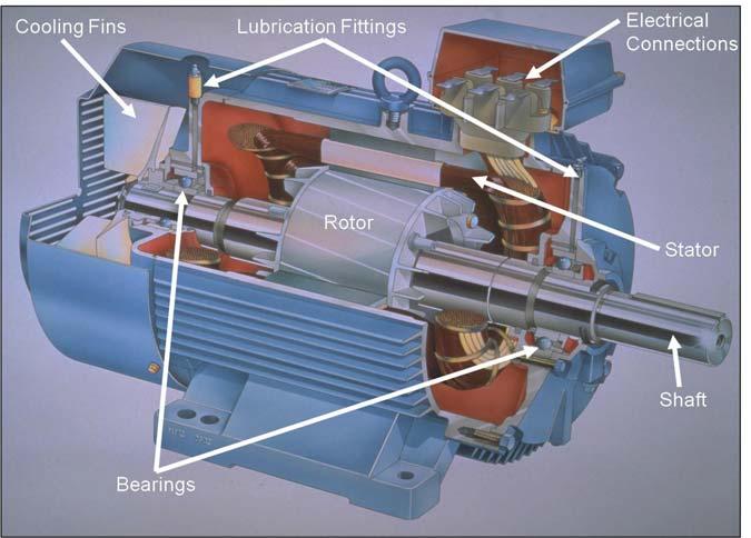
Motor Operation
For best efficiency, follow manufacturer's recommendations for motor maintenance. Proper ventilation prevents overheating and clean motors prevent short circuits. Assessing voltage, connections, bearings, motor ventilation, short-cycling, and overload prevention results in long service.
Keep motor controls free of dust and corrosion. An insulating mat protects operators from shock during operation or maintenance.
Distribution Pumps ©2017, Texas A&M Engineering Extens ion Service. All rights reserved. PM 7 - 23
Figure 7.12: Squirrel cage induction motor. Source:ABB,Inc.
Summary
In this module, we learned about the disinfection, operation, and maintenance of a water distribution system. In the next module, we will overview safety as it pertains to the water utility industry.
Distribution Summary ©2017, Texas A&M Engineering Extens ion Service. All rights reserved. PM 7 - 24
Module 7 Review Questions
1.Storage facilities equalize demand on the water supply.
a.true
b.false
2.Storage allows uniform pump rates, supplies water for firefighting, and provides time for disinfection.
a.true
b.false
3.Ground storage at a surface water treatment plant is called a clean well.
a.true
b.false
4.The TCEQ requires storage tanks to have covered vents, an airtight cover, overruns, and escape hatches.
a.true
b.false
5.If ground storage is the only storage, capacity must be 20 gallons per connection. Otherwise, total storage capacity (elevated storage included) must be 300 gallons per connection.
a.true
b.false
6.If a 30-inch diameter access opening is not provided in a storage tank, the primary roof access must not be less than 30 inches.
a.true
b.false
7.Storage must be painted, disinfected, and maintained according to OSHA standards.
a.true
b.false
8.No paint, coating, or wax containing lead is allowed.
a.true
b.false
Distribution Module 7 Review Questions ©2017, Texas A&M Engineering Extens ion Service. All rights reserved. PM 7 - 25
9.Coatings for contact with potable water must be approved by EPA, the National Sanitation Foundation, or the Food and Drug Administration.
a.true
b.false
10.Elevated storage is a tank, usually steel, supported aboveground on a tower.
a.true
b.false
11.Pressure from an elevated tank is maintained by the height of the water column.
a.true
b.false
12.Each foot of water column produces 0.334 psi.
a.true
b.false
13.Water stored at least 80.85 feet above the highest service connection provides the state’s minimum normal operating pressure of 35 psi.
a.true
b.false
14.A standpipe is a tank resting on the ground that is greater in height than diameter.
a.true
b.false
15.Pressure inside a hydropneumatic tank is provided by air mechanically compressed against the water surface.
a.true
b.false
16.The exterior and interior of ground, elevated, standpipe, and pressure tanks must be inspected monthly.
a.true
b.false
Distribution Module 7 Review Questions ©2017, Texas A&M Engineering Extens ion Service. All rights reserved. PM 7 - 26
17.Storage tank inspection results must be kept at least five years.
a.true
b.false
18.Cathodic protection is an electrochemical method of preventing corrosion of the exterior of metal tanks.
a.true
b.false
19.Ownership signs must include the utility name and emergency phone number at each production, treatment, or storage site.
a.true
b.false
20.Chain link fence material must leave a gap at the ground to trim grass.
a.true
b.false
21.The state requires stored water to have a disinfectant demand.
a.true
b.false
22.After construction or maintenance of a storage tank, a bacteriological sample must be taken after filling the tank.
a.true
b.false
23.If the bacteriological sample is negative, more samples must be taken until two consecutive samples are positive.
a.true
b.false
24.Critical safeguards of a distribution system include a chlorine residual, adequate pressure, bacteriological sampling, and cross-connection control.
a.true
b.false
Distribution Module 7 Review Questions ©2017, Texas A&M Engineering Extens ion Service. All rights reserved. PM 7 - 27
25.The TCEQ requires that distribution pressure never fall below 20 psi, even during emergencies, and normal distribution pressure must be at least 35 psi.
a.true
b.false
26.Material used in water line construction must meet OSHA specifications and should not affect the taste, odor, or quality of the water.
a.true
b.false
27.Plastic pipe must be NSF approved and have an ASTM pressure rating of at least 50 psi or a standard dimension ratio of 62.
a.true
b.false
28.Select pipe on the basis of strength, length, carrying capacity, durability, ease of installation, availability, soil conditions, and cost.
a.true
b.false
29.Prior to January 1, 2014, pipe and fittings containing more than 8.0% lead, or solders and flux containing more than 0.2% lead, are prohibited in a public water supply.
a.true
b.false
30.Isolating valves cut off sections of a system.
a.true
b.false
31.Flushing solves problems of taste, odor, red water, or bad samples.
a.true
b.false
32.The positive displacement meter is the most common design for residential use.
a.true
b.false
Distribution Module 7 Review Questions ©2017, Texas A&M Engineering Extens ion Service. All rights reserved. PM 7 - 28
33.Mains must be no closer than 10 feet, in all directions, from sewers or manholes.
a.true
b.false
34.Trenches for laying six-inch and larger pipe must be at least 18 inches wide and ________ inches wider than the pipe diameter.
35.The top of a pipe in a trench must have at least ________ inches of cover.
36.Do not work in a trench ________ feet or deeper unless it is protected from cave-in.
37.Using timber, plywood, or commercial devices to support an excavation is known as ________.
a.sloping
b.shoring
c.sheeting
d.bracing
38.Shoring is not necessary if the trench walls are sloped to the maximum allowable ________.
a.slant
b.recline
c.dispose
d.slope
Distribution Module 7 Review Questions ©2017, Texas A&M Engineering Extens ion Service. All rights reserved. PM 7 - 29
a.12 b.10 c.8 d.6
a.30 b.24 c.18 d.12
a.7 b.6 c.5 d.4
39.Place spoil banks at least ________ feet from the excavation. a.4 b.3 c.2 d.1
40.Dose new mains with ________ mg/L or more of chlorine at least ________ hours. a.100/3 b.25/24
c.500/24
41.Do not place a main into service until a bacteriological sample is tested with ________ results. a.positive b.no c.negative
d.doubtful
42.One sample is required for each ________ feet of completed main. a.10,000 b.100 c.10
d.1,000
43.Flushing reduces slime and scale buildup, reduces red water complaints, brings chlorinated water to contaminated areas, and removes ________, reducing materials from the system.
a.chlorine
b.iron
c.calcium
d.nitrate
Distribution Module 7 Review Questions ©2017, Texas A&M Engineering Extens ion Service. All rights reserved. PM 7 - 30
b
d.a or
44.Closing a hydrant valve too fast can cause water ________.
a.slammer
b.boomer
c.mallet
d.hammer
45.________ is a buildup of oxidized iron, calcium carbonate, or other chemicals in mains.
a.tuberculosis
b.tuberculation
c.turbidity
d.slime
46.Factors that make water more corrosive are low pH, dissolved oxygen, and ________.
a.free chlorine
b.combined chlorine
c.free iron
d.combined minerals
47.Repairing a leak under some pressure has an advantage of ________.
a.interrupting service
b.reducing contamination risk
c.increasing air in the main
d.ensuring the repair fails under service
48.A cross connection is a physical connection between a public water supply, and 1) another supply of unknown or questionable quality, 2) any source that may contain contamination, 3) any water ________.
a.safe to drink
b.treated to potable quality
c.treated to a greater degree
d.treated to a lesser degree
Distribution Module 7 Review Questions ©2017, Texas A&M Engineering Extens ion Service. All rights reserved. PM 7 - 31
49.The air gap is the only cross-connection control method approved by the TCEQ for protection against ________.
a.water theft
b.air leaks
c.hose sprayers
d.sewage contamination
50.When storms are expected, the water utility should alert personnel, check communications, fill gasoline tanks, check emergency equipment, fill storage tanks, and ________.
a.reduce stock of repair clamps and calcium hypochlorite
b.write emergency procedures
c.isolate elevated storage
d.insulate elevated storage
51.The most common pump in the water utility field is the ________ pump.
a.deep-well turbine
b.centrifugal
c.priming
d.displacement
52.Water is forced out of the volute of a centrifugal pump by ________ force.
a.velocity
b.suction
c.centrifugal
d.turbine
53.Three types of pump curve are head capacity curve, efficiency curve, and ________ curve.
a.gpm
b.psi
c.voltage
d.horsepower
Distribution Module 7 Review Questions ©2017, Texas A&M Engineering Extens ion Service. All rights reserved. PM 7 - 32
54.As the force a pump works against increases, the capacity and efficiency ________.
a.increase
b.decrease
c.equalize
d.stabilize
55.Install a check valve in a pump discharge line to prevent water from flowing ________ during shutdown.
a.back through the pump
b.through a cross connection
c.uphill
d.from supply
56.Common pump problems include ________ and water hammer.
a.proper alignment of pump and motor
b.air-tight suction
c.cavitation
d.unclogged impeller
57.The most common motor is the ________ motor.
a.squirrel cage reduction
b.synchronous
c.squirrel cage deduction
d.squirrel cage induction
Distribution Module 7 Review Questions ©2017, Texas A&M Engineering Extens ion Service. All rights reserved. PM 7 - 33
Distribution Module 7 Review Questions ©2017, Texas A&M Engineering Extens ion Service. All rights reserved. PM 7 - 34
Safety
Terminal Objective
Upon the successful completion of this module, the participant will be able to explain proper safety procedures for water employees.
Enabling Objectives
1.Explain how state and federal laws protect workers.
2.Explain the needed elements for an effective safety program.
3.Describe the main hazards particular to water utility operators.
4.Review chemical safety for water utility employees.
5.Review traffic control for water utility employees.
©2017, Texas A&M Engineering Extens ion Service. All rights reserved.
Module
Safety ©2017, Texas A&M Engineering Extens ion Service. All rights reserved. PM 8 - 2
Introduction
Working in the water and wastewater industry is dangerous! Employees are exposed to chemicals, high voltage, traffic, excavations, deep water, animal bites, confined spaces, and more. However, with the proper attitude and training, accidents can be avoided because they are caused and do not just happen.
We begin this module with a synopsis of hazards applicable to the water utility industry. Various state and federal laws, in addition to utility safety programs, are designed to protect water utility employees.
Federal and State Laws
The federal law regulating workplace safety is the Occupational Safety and Health Act (OSHA). The law applies only to industrial, manufacturing, and private business employers. Although state, municipal, public school, and most federal employers are not required to follow OSHA regulations, they have a moral obligation to provide a safe workplace. Employers not under OSHA may utilize the federal regulations as guidelines for their safety programs.
The “Right-to-Know” Law is a federal law that was adopted by the state as the Texas Hazard Communication Act. This act requires employers not bound by OSHA to provide information about hazardous chemicals in the workplace. This law applies to all state, county, and municipal employees.
One requirement of the Texas Hazard Communication Act is employee access to a Safety Data Sheet (SDS). The SDS is hazardous product information supplied by the manufacturer. An SDS states product hazards and precautions.
Safety Programs
A safety program must start with support from the top official, then extend to all employees. Everyone must participate or the program will fail.
Elements of a safety program include:
•a written policy,
•supportive administration,
•trained employees,
Safety Introduction ©2017, Texas A&M Engineering Extens ion Service. All rights reserved. PM 8 - 3
Safety
Particular Water Utility Hazards
•safety inspections,
•accident review, and
•recordkeeping.
Information for setting up safety programs is available from the Texas Department of State Health Services and the Texas Municipal League. Libraries also have information regarding safety programs.
Particular Water Utility Hazards
Four hazards especially dangerous to water utility operators are:
•confined space entry,
•excavation and trenching,
•chemical handling, and
•traffic.
Confined Space Entry
Confined Space Definition
According to OSHA 29 CFR Part 1910.146, three criteria classify a confined space.
A confined space is 1) large enough and so configured that an employee may enter and do work; 2) has limited or restricted means of entry or exit; and 3) is not designed for continuous occupancy.
Examples of confined spaces are vaults, pits, water tanks, storage tanks, pump rooms, and trenches.
Hazard Categories
The hazards to water utility employees are as follows:
•Hazardous atmospheres—such as a lack of oxygen
•Engulfment—while working in a tank that begins to fill
•Chemical—exposure to hazardous chemicals
•Mechanical—exposure to moving components of machinery
•Electrical—exposure to energized electrical equipment
©2017, Texas A&M Engineering Extens ion Service. All rights reserved. PM 8 - 4
Oxygen (in air)
O2
•Biological—exposure to human waste
•Radiological—exposure to radioactive material
The number one cause of death in a confined space is lack of oxygen.
Gases
Combustible gases include methane, hydrogen sulfide, and carbon monoxide. Hydrogen sulfide and carbon monoxide are monitored with a toxic sensor because they are toxic long before they are combustible.
Do not rely on sense of smell or sight to identify any gas. Cockroaches are not gas detectors! They can adapt to conditions that would kill a human. Use a direct reading instrument to check first for oxygen content, then combustibles, then toxins, in that order.
Refer to Table8.1 for a listing of gases and their characteristics.
Table 8.1: Gases
Colorless, odorless, tasteless, nonpoisonous. Supports combustion.
Normal air contains 20.9% O2. Humans tolerate down to 12%. Less than 5–7% likely to be fatal.
Poor ventilation or chemical consumption of available O2
Oxygen deficiency indicator.
Carbon Monoxide CO
Colorless, odorless, nonirritating, tasteless. Flammable, explosive.
0.2–0.25% causes unconsciousness in 30 minutes. Blood will absorb CO more readily, causing oxygen starvation.
Product of incomplete combustion.
CO ampoules.
Methane CH4
Colorless, odorless, tasteless, nonpoisonous. Flammable, explosive.
Deprives tissues of oxygen, an apshyxiant.
Natural gas, marsh gas, fuel gas, and sewer gas.
Combustion gas indicator. Oxygen deficiency indicator.
Safety Particular Water Utility Hazards ©2017, Texas A&M Engineering Extens ion Service. All rights reserved. PM 8 - 5
on Humans Most Common Sources Method of Testing
Gas and Symbol Properties Effect
Gas and Symbol Properties
Hydrogen Sulfide H2S
Colorless, poisonous. Rotten egg odor in small concentrations, odor not evident at high concentrations. Flammable, explosive.
Effect on Humans
Death in a few minutes at 0.2%. Paralyzes respiratory center.
Most Common Sources Method of Testing
Petroleum fumes, blasting fumes, sewer gas.
H2S analyzer. H2S ampoules.
Carbon Dioxide CO2
Colorless, nonflammable, odorless. Not usually present in dangerous amounts unless oxygen is already deficient.
10% is fatal after a few minutes. Acts on nerves of respiration.
Issues from carbonaceous rock layers. Sewer gas.
Oxygen deficiency indicator.
Chlorine Cl2
Greenish-yellow gas, amber in liquid state. Penetrating odor. Highly corrosive in the presence of moisture.
Highly irritating to eyes and mucous membranes. Causes violent coughing. Heavy exposure is fatal.
Confined Space Program
Leaking connections, overdosage in treatment.
Chlorine detector. Ammonia vapor gives off white fumes. Oxygen deficiency indicator.
The employer must identify all confined spaces and determine their hazards. After evaluation, the spaces are designated “permit required” or “non-permit required.” The employer must train operators to work safely in confined spaces and must provide them with safety equipment.
A non-permit confined space is defined as a confined space that does not contain or, with respect to atmospheric hazards, have the potential to contain any hazard capable of causing death or serious physical harm. If an employer can document that forced air ventilation will eliminate all atmospheric hazards the space may be classified as non-permit required.
Safety Particular Water Utility Hazards ©2017, Texas A&M Engineering Extens ion Service. All rights reserved. PM 8 - 6
Table 8.1: Gases (Continued)
“Permit-required” confined space (permit space) means a confined space that has one or more of the following:
•Contains or has potential to contain a hazardous atmosphere
•Contains a material that has potential for engulfing an entrant
•Has an internal configuration such that an entrant could be trapped/asphyxiated by inwardly converging walls or by a floor that slopes downward and tapers to a smaller cross section
•Contains any other recognized serious safety/health hazard
When entering a “permit required” space, personnel must wear a harness and be attached to a retrieval line. OSHA requires an anti-fall line if a portable ladder or stairs are not used. When a vertical entry of five feet or more is made, the retrieval line must be attached to a mechanical retrieval device. This allows a non-entry rescue.
Rescuers must be trained in confined space rescue and be available before an entry occurs. They do not have to be on site, but must be able to respond in appropriate time.
Excavation and Trenching
For years, Texas had more deaths due to cave-ins than any other state. The legislature passed laws requiring private employers such as contractors to follow OSHA excavation and trenching rules (OSHA 29 CFR Part 1926.650-653). These regulations do not apply to state, county, or municipal employers.
Cave-In Protection
When an excavation is five feet or deeper, a means of cave-in protection is required. This can be shoring, shielding, or sloping. Shoring, shielding, and sloping protect workers from collapsing trench walls.
Shoring uses timbers or hydraulic wedges and sheeting (Figure8.1 and Figure8.2).
Safety Particular Water Utility Hazards ©2017, Texas A&M Engineering Extens ion Service. All rights reserved. PM 8 - 7
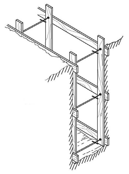
Safety Particular Water Utility Hazards ©2017, Texas A&M Engineering Extens ion Service. All rights reserved. PM 8 - 8
Figure 8.1: Aluminum hydraulic shoring. Source: TEEX.
2’ MAX. VERTICAL SPACING 4’ MAX. WALE HYDRAULIC CYLINDER HORIZONTAL SPACING UPRIGHT SHEETING
Figure 8.2: Trench shoring in hard ground. Source: TEEX.
Shields or trench boxes are movable, and cannot prevent a cave-in. Therefore, workers must stay within the shield or box (Figure8.3).
Benching is a type of sloping done by cutting stair steps in the trench wall while maintaining the maximum allowable slope (Figure8.4).
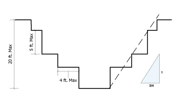
Sloping cuts trench walls to the angle that overcomes collapsing pressure. Soil type determines the maximum allowable slope or angle of repose. OSHA classifies soil into four categories: stable rock, and types A, B, or C. If the soil is previously disturbed, it is type C (Table8.2).
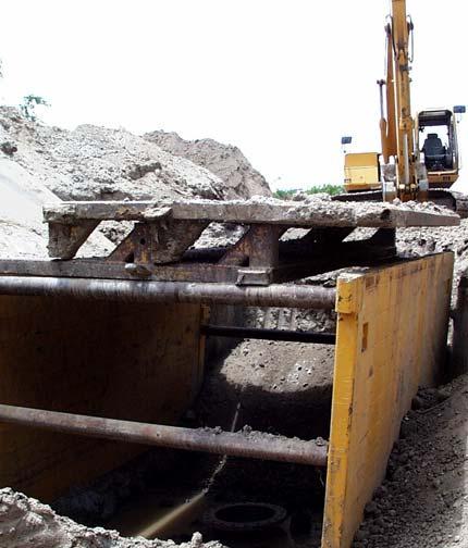
Safety Particular Water Utility Hazards ©2017,
Engineering
PM 8 - 9
Texas A&M
Extens ion Service. All rights reserved.
Figure 8.3: Trench box. Source: TEEX.
Figure 8.4: Benching. Source: TEEX.
The maximum allowable slope is utilized when sloping the trench walls to prevent the trench from caving in. If in doubt about the soil type always consider it a Type C soil, requiring a 34o angle from horizontal. This is done by using the run to rise listed in the chart. For a Type C soil this is 1½ ft. run to 1 ft. rise. The backhoe operator would dig 1½ ft. horizontally while going up only 1 ft. Continuing to excavate in this manner would ensure a 34o slope. It is important to excavate both sides of the trench in this manner.
Trench Exits and Spoil
If the excavation is four feet or deeper, a means of exit must be provided. Ramps or ladders are acceptable. If a ladder is used, it must extend at least three feet above the top of the excavation, be secured, and be within 25 feet laterally of anyone in the excavation.
Excavation spoil must be kept at least two feet from the excavation edge. Spoil is the material excavated from an excavation.
Chemical Safety
Water utility employees may use dangerous chemicals everyday and have a right to product information under the Texas Hazard Communication Act (Right to Know law). The components of the act are as follows:
•A written program
•Posted “Notice to Employees”
•Personal protection equipment
•Hazardous material training
•Safety Data Sheets (SDS)
•Employee rights protection
•State notification of chemical injuries
Safety Chemical Safety ©2017, Texas A&M Engineering Extens ion Service. All rights reserved. PM 8 - 10
Soil Types Maximum Allowable Slope Horizontal Run to Vertical Rise Stable rock90° 0 Type A 53° ¾:1 Type B45° 1:1 Type C 34° 1½:1
Table 8.2: Classification of Soil Types and Angles for Sloping
Traffic Control
Improper warning signs and barricades cause most work area accidents on streets and highways. Traffic control must not confuse motorists. Workers should be trained from the Texas Manual on Uniform Traffic Control Devices (TMUTCD), Texas Department of Transportation, Austin (Figure8.5).


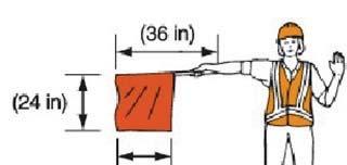
Summary
Safety is a concern for employees in any industry. It is important to understand policies and procedures and their role in the water utility industry because of their importance to the well-being of water utility employees.

Safety Traffic Control ©2017, Texas A&M Engineering Extens ion Service. All rights reserved. PM 8 - 11
Figure 8.5: Traffic control flaggers. Source: TxDOT.
©2017, Texas A&M Engineering Extens ion Service. All rights reserved. PM 8 - 12
Safety Summary
Module 8 Review Questions
1.Nine out of ten accidents result from unsafe acts of the person injured or someone else.
a.true
b.false
2.The federal law regulating workplace safety is the Occupational Safety and Health Act.
a.true
b.false
3.The Texas Hazard Communication Act is known as the “Right to Work” law.
a.true
b.false
4.A safety program must start from the bottom, and then extend to the top official.
a.true
b.false
5.Everyone must participate in a safety program or it will fail.
a.true
b.false
6.A confined space is 1) large enough to enter and do work; 2) has limited or restricted entry or exit; and 3) is not designed for continuous occupancy.
a.true
b.false
7.The number one cause of death in a confined space is lack of oxygen.
a.true
b.false
8.Combustible gases include methane, hydrogen sulfide, and carbon dioxide.
a.true
b.false
Safety Module 8 Review Questions ©2017, Texas A&M Engineering Extens ion Service. All rights reserved. PM 8 - 13
9.Cockroaches can adapt to conditions that would kill a human.
a.true
b.false
10.After evaluation, confined spaces are designated “entry allowed” or “entry denied.”
a.true
b.false
11.When entering a “permit required” space, personnel must wear a harness and be attached to a ________ line.
a.life
b.retrieval
c.tow
d.drag
12.OSHA requires an anti-fall line if a portable ladder or ________ are not used.
a.shoring
b.trench boxes
c.stairs
d.ropes
13.When a vertical entry of ________ feet or more is made, the retrieval line must be attached to a mechanical retrieval device.
a.5
b.4
c.3
d.50
14.Private employers, such as contractors, must follow ________ excavation and trenching rules.
a.OSHA
b.AWWA
c.TCEQ
d.EPA
Safety Module 8 Review Questions ©2017, Texas A&M Engineering Extens ion Service. All rights reserved. PM 8 - 14
15.When an excavation is ________ feet or deeper, a means of cave-in protection is required.
a.2
b.3
c.4
d.5
16.Cave-in protection includes shoring, shielding, and ________.
a.ventilation
b.personal protective equipment
c.sloping
d.flagging
17.Shoring uses timbers or hydraulic wedges and ________.
a.sheeting
b.nails
c.steel cables
d.ropes
18.Benching is a type of sloping done by cutting stair steps in the trench wall while maintaining the maximum allowable ________.
a.spoil
b.slip
c.slide
d.slope
19.Sloping cuts trench walls to the angle that overcomes collapsing ________.
a.soil
b.spoil
c.pressure
d.tension
Safety Module 8 Review Questions ©2017, Texas A&M Engineering Extens ion Service. All rights reserved. PM 8 - 15
20.OSHA classifies soil into four categories: ________ rock, class A, class B, and class C.
a.hard
b.stable
c.soft
d.sharp
21.If the soil is previously disturbed, it is ________.
a.stable rock
b.class A
c.class B
d.class C
22.A maximum allowable slope of 45° and a run to rise of 1:1 is for soil type ________.
a.stable rock
b.class A
c.class B
d.class C
23.If the excavation is ________ feet or deeper, a means of exit must be provided.
24.If a ladder is used, it must extend at least ________ feet above the edge of the excavation and be within ________ feet laterally of anyone in the excavation. a.3/30 b.2.5/25
Safety Module 8 Review Questions ©2017, Texas A&M Engineering Extens ion Service. All rights reserved. PM 8 - 16
a.4
c.3 d.2.5
b.3.5
c.2/20 d.3/2
25.Excavation spoil must be kept at least ________ feet from the excavation.
a.2
b.3
c.4
d.5
26.Water utility employees have a right to product information under the ________.
a.Texas Right to Work Act
b.Texas Hazardous Material Act
c.Texas Hazard Communication Act
d.Texas Hazardous Product Act
27.One of the components of the Texas Hazard Communication Act is employee access to ________.
a.DSS
b.SSD
c.SDS
d.DDS
28.To prevent work area accidents, workers should be trained from the Texas Manual on Uniform Traffic Control Devices, ________, Austin.
a.Texas Department of Streets and Highways
b.Texas Highway Department
c.Texas Department of Transportation
d.Texas Department of Public Safety
Safety Module 8 Review Questions ©2017, Texas A&M Engineering Extens ion Service. All rights reserved. PM 8 - 17
Module 8 Review Questions ©2017, Texas A&M Engineering Extens ion Service. All rights reserved. PM 8 - 18
Safety
Calculations
Terminal Objective
Upon the successful completion of this module, the participant will be able to calculate problems related to basic water works operations.
Enabling Objectives
1.Calculate area of squares, rectangles, and circles.
2.Calculate volume in cubic feet and gallons of rectangular and cylindrical tanks.
3.Solve problems requiring the use of conversion factors.
4.Solve problems involving chemical dosage.
5.Solve problems of detention time in days, hours, and minutes.
©2017, Texas A&M Engineering Extens ion Service. All rights reserved.
Module
Calculations ©2017, Texas A&M Engineering Extens ion Service. All rights reserved. PM 9 - 2
Introduction
An an employee of a water/wastewater utility, you can expect to rely on mathematical equations to solve basic water/wastewater operations problems. In this module, we will solve various problems related to the industry using multiple mathematical formulas.
Area Area of a Rectangle or Square
Formula: Area = Length × Width

Look at the rectangle (Figure9.1) below.
The length is 6 feet and the width is 5 feet.
Total surface area is 6 × 5 = 30 ft2.
The little “2” after “ft” is a symbol for square units. It means there are two dimensions in the formula for area of a rectangle or square. Area is usually expressed in inches, feet, yards, or miles, but may be expressed in other units.
Calculations Introduction ©2017, Texas A&M Engineering Extens ion Service. All rights reserved. PM 9 - 3
Figure 9.1: Rectangle. Source: TEEX.
Area of a Circle
Formula: A = R2 (3.14 × Radius × Radius)
(pi) is the 16th letter of the Greek alphabet and represents the number 3.14, which is the ratio of the circumference to the diameter of a circle. The circumference of a circle is 3.14 times the diameter. The circumference of a circle divided by its diameter is 3.14 ().
Circumference (C) is the distance around a circle. Diameter (D) is the distance through the center of a circle. Radius is half the diameter of a circle (Figure9.2).
Area is usually expressed in square units.
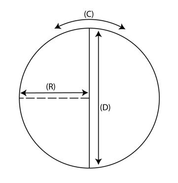
Calculations Area ©2017, Texas A&M Engineering Extens ion Service. All rights reserved. PM 9 - 4
Figure 9.2: Radius of a circle. Source: TEEX.
Activity 9.1: Area Calculations
1.What is the surface area of the bottom of a rectangular storage tank 10 feet long and five feet wide?
2.How many square feet is the roof of a chlorinator room eight feet square?
3.If a trench is 50 feet long and six feet wide, how many square feet will the bottom cover?
4.What is the surface area of the bottom of a circular storage tank 20 feet in diameter?
Calculations Area Calculations ©2017, Texas A&M Engineering Extens ion Service. All rights reserved. PM 9 - 5
5.What is the surface area of a 35-foot diameter circular roof covering a service center?
6.How many square inches and square feet is the end section of a 6-inch pipe?
7.How many square feet is the end section of an 18-inch pipe?
8.How many square feet is the end section of a 24-inch pipe?
9.How many square feet is the end section of a 36-inch pipe?
Calculations Area Calculations ©2017, Texas A&M Engineering Extens ion Service. All rights reserved. PM 9 - 6
Volume
Volume of a Rectangular Box or Cube
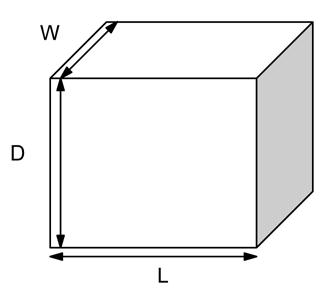
Formula: Volume= Length × Width × Depth
The length of the box (Figure9.3) is 6 feet, the width is 3 feet, and the depth is 4 feet. The volume is 6 × 3 × 4 = 72 ft3.
The little 3 after “ft” is a symbol for cubic units. It means there are three dimensions in the formula.
Volume of a Vertical Cylinder
Formula: V= R2 × Depth
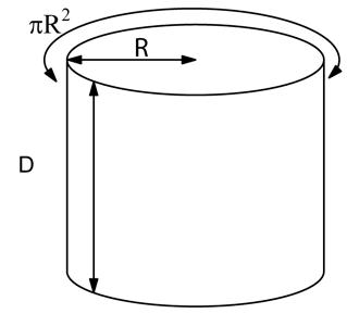
Calculations Volume ©2017, Texas A&M Engineering Extens ion Service. All rights reserved. PM 9 - 7
Figure 9.3: Rectangular box/cube. Source: TEEX.
Figure 9.4: Vertical cylinder. Source: TEEX.
The cylinder diameter is 20 feet (radius 10’) and the depth (D) is 18 feet (Figure9.4). The volume is 3.14 × 10’× 10’ × 18’ = 5,652 ft3
To calculate the capacity in gallons, multiply cubic feet by 7.48 gal/ft3 .
To calculate the volume in cubic yards, divide cubic feet by 27 ft3/yd3
Volume of a Horizontal Cylinder
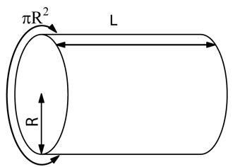
Formula: V= R2 x Length
The cylinder (Figure9.5) is 4 feet in diameter (radius 2’) and the length (L) is 9 feet. The volume is 3.14 × 2’× 2’ × 9’ = 113.04 ft3
Multiply cubic feet by 7.48 to calculate capacity in gallons per ft3.
The following is a shortcut to calculating how many gallons are in a single foot of pipe:
1.Square the diameter of the pipe. (diameter x diameter) or d2
2.Multiply the result by a factor of 0.0408.
3.Finally, multiply that result by the distance of pipe in feet to calculate total gallons for that distance.
Example for a 6" pipe that is 1' in length:
6 x 6 × 0.0408 × Length (1') = gallons in 1' of pipe
36 x 0.048 x 1 = 1.47 total gallons
Example for a 6" pipe that is 45' in length:
(6)2 × 0.0408 × Length (45') = gallons in 45' of pipe
36 x 0.048 x 45 = 66 total gallons
Calculations Volume ©2017, Texas A&M Engineering Extens ion Service. All rights reserved. PM 9 - 8
Figure 9.5: Horizontal cylinder Source: TEEX.
Activity 9.2: Volume Calculations
1.How many gallons of water will a 20,000-cubic foot tank hold?
2.How many cubic yards (yd3) of dirt are removed from a trench that is 60 feet long, 5 feet wide, and 5 feet deep?
3. A rectangular storage tank is 25 feet wide, 40 feet long, and 10 feet deep. What is the volume in cubic feet and capacity in gallons?
4.Calculate the cubic yards of dirt removed from a trench 2,000 feet long, 4 feet wide, and 6 feet deep.
Calculations Volume ©2017, Texas A&M Engineering Extens ion Service. All rights reserved. PM 9 - 9
5.Find the volume in cubic feet (ft3) and capacity in gallons of a clarifier 60feet in diameter and 12 feet deep.
6.A sedimentation tank is 55 feet in diameter and 12 feet deep. What is the capacity in gallons?
7.A chemical mixing tank 15 square feet and 15 feet deep will hold how many gallons of alum?
8.A bleach tank has a radius of 3 feet and is 9 feet deep. How many gallons are in the tank if it is only one-quarter full?
9.How many gallons will 500 feet of 6-inch pipe hold?
Calculations Volume ©2017, Texas A&M Engineering Extens ion Service. All rights reserved. PM 9 - 10
Conversion Factors
Formulas
8.34 pounds per gallon1 acre-foot = 1 acre that is 1 foot deep
7.48 gallons per cubic foot acre - feet = acres x feet of depth
100 gallons/person/day27 cubic feet per cubic yard
0.17 lbs. BOD/person/day 5,280 feet per mile
1 acre = 43,560 square feet1,440 minutes per day
mgd = million gallons per day 1 cubic foot per second (cfs) = 449 gpm
part whole 100 percent = wholepart –whole - 100 percent removal =
.433 psi = foot of water column 1 psi = 2.31 feet of water column
Static level is the water level while the pump is off, measured from ground level. Pumping level is the water level while the pump operates, measured from ground level. Drawdown is the difference between static level and pumping level.
Calculations Conversion Factors ©2017, Texas A&M Engineering Extens ion Service. All rights reserved. PM 9 - 11
Table9.1 provides a list of common conversion factors.
Table 9.1: Conversion Factors
Activity 9.3: Conversion Factor Calculations
1.How many gallons of water will a 1,000-cubic foot tank hold?
2.What is the weight of water in a 14,000-cubic foot storage tank?
3.How many cubic yards of concrete are needed to fill 108 square feet 1 foot deep?
4.How many 20-foot sections of pipe are needed for 1.5 miles of main?
Calculations Conversion Factors ©2017, Texas A&M Engineering Extens ion Service. All rights reserved. PM 9 - 12
5.What is the mgd flow of a treatment plant producing 800,000 gallons per day?
6.Change 300 gpm to gallons per day. What is the number in mgd?
7.How many mgd does a 700-gpm pump produce?
8.Change 0.5 mgd to gallons per minute.
9.The static level in a well is 245 feet and the pumping level 308 feet. What is the drawdown?
Calculations Conversion Factors ©2017, Texas A&M Engineering Extens ion Service. All rights reserved. PM 9 - 13
10.The pumping level of a well is 401 feet. If the drawdown is 19 feet, what is the static level?
11.What does a pressure gauge read at the base of a full elevated tank if the water level is 140 feet above the ground?
12.What is the height of a column of water with a base pressure of 43.3 psi?
13.A business uses 800 gallons of water per day and is charged $2.50 per 1,000 gallons. What is the cost for a 30-day month?
14.A residence has a 1-gallon per minute leak. If the leak is undetected for a 30-day month, what is the cost in wasted water at $3.00 per thousand gallons? Assume the meter reader records only 1,000s of gallons
Calculations Conversion Factors ©2017, Texas A&M Engineering Extens ion Service. All rights reserved. PM 9 - 14
15.If treatment reduces a water hardness of 250 mg/L by 60%, what mg/L remains?
Calculations Conversion Factors ©2017, Texas A&M Engineering Extens ion Service. All rights reserved. PM 9 - 15
Dosage
To calculate dosage for water treatment, use the following formulas:
lbs./day = mgd × 8.34 pounds per gallon × mg/L
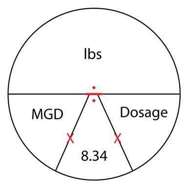
mg/L
lbs./gal mgd x 8.34 pounds per gallon - =
Note: The formulas listed above can be thought of in the relationship below (Figure9.6).
lbs. hypochlorite
lbs. per Cl 2 decimal fraction hypochlorite - =
Dosage = Demand + Residual
Demand = Dosage - Residual
Residual = Dosage - Demand
©2017, Texas A&M Engineering Extens ion Service. All rights reserved. PM 9 - 16
Calculations Dosage
Figure 9.6: Dosage circle. Source: TEEX.
Activity 9.4: Dosage Calculations
1.A sample of treated surface water has a chlorine demand of 3.5mg/L. If the operator wants a residual of 1 mg/L, what dosage must the operator apply?
2.If an operator applies a chlorine dosage of 2.75 mg/L to 5,000 gallons of treated wastewater and the chlorine demand is 1.25 mg/L, what will be the mg/L residual?
3.An operator applies 7 mg/L of chlorine to effluent containing hydrogen sulfide. If the hydrogen sulfide reacts with all but 2.5 mg/L of the chlorine, what is the chlorine demand?
4.After flushing a fire hydrant for 10 minutes at 200 gpm, a water sample shows a chlorine residual of 4.8 mg/L. If the chlorine demand is 2.2, what is the dosage?
Calculations Dosage ©2017, Texas A&M Engineering Extens ion Service. All rights reserved. PM 9 - 17
5.The following alum dosages were applied during surface water treatment:
5 mg/Lmidnight to 6 a.m
30 mg/L6 a.m. to 10 a.m
25 mg/L10 a.m. to 6 p.m.
15 mg/L6 p.m. to midnight
What is the average dosage per hour for that day?
6.A surface water treatment plant produces 1,600,000 gallons per day using alum at 9 mg/L dosage. How many pounds of alum are used per day, per hour, and per 30-day month?
7.An operator is using a 150-pound chlorine cylinder and treating 5,000,000 gallons per day. At a dosage of 1.5 mg/L, is the safe withdrawal rate (vacuum transmission) exceeded if the chlorinator room is 75oF?
8.How many pounds of fluorosilic acid are used daily at a dose of 1mg/L if a well produces 500 gallons per minute?
Calculations Dosage ©2017, Texas A&M Engineering Extens ion Service. All rights reserved. PM 9 - 18
9.Lime is used in a surface water treatment plant at the rate of 480pounds per day. If the plant produces 2,400,000 gallons daily, what is the mg/L dosage?
10.If a well pumps 650 gpm and uses 1.5 pounds of chlorine per hour, what is the mg/L dosage per day?
11.A water system uses 50 pounds of chlorine per day, but runs out a day before a delivery is made. If calcium hypochlorite (65%) is substituted, will 100 pounds last until delivery? Calculate the answer two ways
Calculations Dosage ©2017, Texas A&M Engineering Extens ion Service. All rights reserved. PM 9 - 19
Detention Time
Use the following formulas to calculate detention time:
Tank capacity in gallons
Flow rate - Detention time =
Tank capacity in gallons
Flow rate gpd - Time in days =
Tank capacity in gallons
Flow rate gph - Time in hours =
Tank capacity in gallons
Flow rate gpm - Time in minutes =
Activity 9.5: Detention Time Calculations
1.How many minutes will it take to fill a 4,000-gallon wet well at 400 gpm?
2.How many hours will it take to empty a 20,000-gallon tank at 60gpm?
©2017, Texas A&M Engineering Extens ion Service. All
PM 9 - 20
Calculations Detention Time
rights reserved.
3.How many days will it take to fill a 300,000-gallon wet well at 100 gpm?
Summary
4.A sedimentation tank is 75 feet long, 35 feet wide, and 15 feet deep. What is the detention time in hours at a flow rate of 2 mgd?
5.A ground storage tank is 20 feet in diameter and 10 feet deep. At 11 a.m., an operator begins filling it at 500 gpm. Will the operator be late for lunch at noon?
The formulas and problem calculations reviewed in this module may be applied daily in the water utility industry. It’s important to understand the variables, formulas, and results of these mathematical equations.
Calculations Summary ©2017, Texas A&M Engineering Extens ion Service. All rights reserved. PM 9 - 21
Calculations Summary ©2017, Texas A&M Engineering Extens ion Service. All rights reserved. PM 9 - 22
©2017, Texas A&M Engineering Extens ion Service. All rights reserved. Module
Activities
End-of-Course
End-of-Course Activities
©2017, Texas A&M Engineering Extens ion Service. All rights reserved. PM 10 - 2
Introduction
During this module, participants will review the course, complete the course examination to assess satisfactory completion of the course, and complete closing activities.
Key Points
Review key points from the following topics that were presented in this course:
•The responsibilities of a water utility operator
•How a water employee can demonstrate good public relations.
•The attributes of water from various sources
•How groundwater is made usable
•How surface water is made usable
•The process for the disinfection of water
•The common methods of water delivery to the public following water treatment
•Proper safety procedures for water employees
•How to calculate problems related to basic water works operations
Course Examination
Participants will complete a 30-question, multiple choice exam. The written final exam will be used as part of the instructor’s evaluation for successful completion of the class.
Closing Activities
Complete closing activities.
Participant Evaluation Surveys
Participants will complete the TEEX Participant Evaluation Survey Upon completion, one participant will collect the surveys, place them in an envelope, and seal the envelope.
Please be sure to answer all questions on both front and back pages of the survey.
End-of-Course Activities Introduction ©2017, Texas A&M Engineering Extens ion Service. All rights reserved. PM 10 - 3
End-of-Course Activities
Closing Activities
Certificates
Participants who have successfully completed ALL course requirements will receive a Certificate of Completion at the end of the class if they were preregistered at least two weeks before the start of the class. If an eligible participant does not receive the certificate at the end of the class, or if the certificate needs to be returned for correction, the certificate will be mailed to the participant.
©2017, Texas A&M Engineering Extens ion Service. All rights reserved.
PM 10
4
-
Acid. A substance that disassociates in water-forming hydrogen ions.
Acidity. Capacity of an aqueous solution to react with hydroxyl ions.
Aeration. Bringing water into contact with air.
Air gap. An air space between the end of a supply pipe and unsafe or unknown quality water.
Algae. One of single- or multi-celled plant, mostly aquatic and microscopic.
Alum. A coagulant used in water treatment.
Aquifer. A porous, underground, water-bearing formation yielding a useful supply of water.
Artesian well. Groundwater under sufficient pressure to rise above the aquifer containing it.
Atom. The smallest unit of a chemical element composed of protons, neutrons, and electrons.
AWWA. American Water Works Association.
Backfill. The soil or select material placed in an excavation after the pipe is laid.
Backflow. Flow reversal by back siphonage or back pressure higher than supply pressure.
Back pressure. Increase in downstream pressure above the supply pressure.
Bacteria. Microscopic organisms.
Bacteriological samples. Water samples analyzed for microorganisms present.
Basicity. Capacity of an aqueous solution to react with hydrogen ions or pH above 7.
Carbon dioxide. A gas formed by the combustion or decomposition of organics.
Chloramines. Disinfectants formed by the reaction of ammonia with chlorine.
Chlorinator. Device used to apply chlorine to water.
Chlorine. A heavy, greenish-yellow gas with a pungent odor.
Chlorine demand. Amount of chlorine reacted with reducing agents.
Chlorine dosage. Amount of chlorine applied to water in mg/L or ppm.
Chlorine residual. Amount of chlorine remaining after reaction with demand.
Clay. Plastic, earthy, finely divided soil.
Clear well. A ground storage tank at a water treatment plan containing treated water.
Coagulation. Chemical neutralization of suspended and dissolved solids by molecular charges causing clotting.
©2017, Texas A&M Engineering Extens ion Service. All rights reserved.
Appendix
Glossary
Coliform bacteria. Bacteria found on plants, in soil, and in the intestines of warm-blooded organisms.
Combined chlorine residual. Chlorine combined with ammonia (chloramines).
Compliance. Obedience to a requirement.
Contamination. Toxins in water making it unsafe to drink.
Corporation cock. A valve connecting a water main to a service line.
Corrosive. Tendency to destroy or oxidize metal.
Cross connection. A physical connection between a public water system and either another supply of unknown or questionable quality, any source that may contain contaminating or polluting substances, or any source of water treated to a lesser degree in the treatment process.
Detention time. Time water is contained in a tank at a given flow rate.
Disinfection. Killing or inactivation of pathogenic bacteria.
Dissolved solids. Solids in water that cannot be removed by filtration.
Distribution. Transporting water in pipes. Drain field. Ground receiving septic tank discharge.
Elevated storage. A water tank raised at least 81 feet above the highest service connection.
Employee relations. Relationship between employer and employees.
EPA. Environmental Protection Agency.
Evaporation. The changing of liquid water into vapor.
Fecal. Pertaining to intestinal waste.
Filtration. Removal of suspended material from water by a filter.
Floc. Suspended solids clotted together by chemicals.
Flocculation. The formation of larger floc in water.
Flush. To wash or rinse by water. Free chlorine residual. Uncombined chlorine after all reactions have taken place.
Gravel pack. Gravel placed around well screens to reduce the intake of sand.
Ground storage. Tanks storing water at ground level.
Groundwater. Water contained in aquifers. Hard water. Water in which soap lathers poorly, usually caused by calcium and magnesium.
Hazardous atmospheres. Toxic gases, explosive or flammable conditions, oxygen deficiency.
Hydrogen sulfide. Poisonous gas that smells like rotten eggs.
Hydrologic cycle. Natural movement of water between the earth and atmosphere.
Hypochlorination. The use of calcium hypochlorite or sodium hypochlorite to disinfect water.
Hypochlorite. Calcium hypochlorite or sodium hypochlorite.
Impervious. Incapable of penetration, such as by water.
Impurities. Any matter in water.
Indicator organisms. Fecal coliform, which indicate fecal contamination.
Ion exchange. Treatment process in which ions from two different molecules are exchanged.
©2017, Texas A&M Engineering Extens ion Service. All rights reserved. PM A - 2
Latrine. A ditch or other such receptacle used as a toilet.
Lime. A chemical, calcium oxide, used to increase water alkalinity.
Meter. Measuring device for water flow.
Methane. A gas produced by the anaerobic decay of organic matter.
mg/L. Milligrams per liter equal to parts per million (ppm).
Microorganisms. Microscopic life visible with an optical or electron microscope.
Monitor. To keep track of or record.
Murkiness. Cloudiness caused by suspended particles in water.
Organic. Of human, animal, or vegetable origin, or of carbon structure.
Overpumping. Pumping in excess of recharge.
Percolation. Processed by which water moves downward through soil.
pH. Concentration of the hydrogen ion in gram atoms per liter; neutral water (pH 7) has a hydrogen ion concentration of 10–7.
Positive displacement meter. One of the most common meter designs in the water industry.
Precipitation. Rain, snow, sleet, and hail.
Professionalism. Technical knowledge and ethical standards of a profession.
Public relations. Relationship between the water utility and the public.
PVC. Polyvinyl chloride; a plastic used for pipe.
Reservoir. Body of water stored for public use or a water storage tank for public use.
Respirator. Device worn over the mouth and nose for protection from gases or mists.
Reverse osmosis. Dissolved and suspended solid removal under pressure by membrane filtering.
Runoff. Precipitation that runs off into lakes and streams.
Sanitation. Cleanliness.
Scale. Mineral deposits formed on surfaces. Sedimentation. Settling of floc or suspended matter in a sedimentation basin.
Settled solids. Suspended solids settled to the bottom of a tank.
Silt. Fine soil suspended in water.
Sludge. Settled floc or suspended solids.
Sodium. An element and component of table salt (sodium chloride).
Sodium thiosulfate. A chemical used to neutralize chlorine.
Softening. Removal or counteracting hardness.
Spoil bank. Excavated material piled along the ditch.
Spring. Where an aquifer reaches the surface. Standpipe storage. A tank standing on the ground greater in height than width.
Stuffers. Public information included with the monthly utility bill.
Subsidence. Sinking of land due to groundwater withdrawal; common on the coast.
Surface water. Water in lakes, streams, rivers, and reservoirs.
Suspended solids. Solids that can be removed by filtration.
TDSHS. Texas Department of State Health Services.
©2017, Texas A&M Engineering Extens ion Service. All rights reserved. PM A - 3
Total chlorine residual. Combined chlorine residual plus free chlorine residual.
Total solids. Suspended and dissolved solids combined.
Toxic. Poisonous.
Transpiration. Evaporation of water vapor from plants into the atmosphere.
Transportation. Carried from one point to another.
Trench. A ditch deeper than its width. Turbidity. Suspended particles that scatter light.
Tuberculation. Buildup of calcium carbonate or other deposits.
TCEQ. Texas Commission on Environmental Quality.
Usage. Amount of water used.
Valve. Device used for controlling water. Water table. Top surface of an unconfined aquifer.
Well casing. A pipe cemented into an aquifer, preventing well collapse and contamination.
Well screen. A slotted, drilled, or wire-wrapped pipe of corrosion-resistant material used to block sand.
©2017, Texas A&M Engineering Extens ion Service. All rights reserved. PM A - 4
Chlorine Procedures
©2017, Texas A&M Engineering Extens ion Service. All rights reserved. Appendix
©2017, Texas A&M Engineering Extens ion Service. All rights reserved. PM B - 2
Chlorine Procedures
Analytical Methods
Two methods will be summarized in this manual:
•DPD-FAS Titrimetric: Standard Methods 4500-Cl F
•DPD Spectrophotometric: Standard Methods 4500-Cl G
Refer to each method and follow all procedure steps as written.
Chemistry of DPD Ferrous Titrimetric Analysis
Chlorine and chloramines stoichiometrically liberate iodine from potassium iodide at pH 4.0 or less. The iodine is titrated with ferric ammonium sulfate (FAS) using N,N-diethyl-p-phenylenediamine (DPD) as the indicator. The results are calculated as mg/L Cl even though the actual measurement is of the total oxidizing power because chlorine is the dominant oxidizing agent present.
Stoichiometrically: Calculation of the quantities of reactants and products in a chemical reaction; can be described as the quantitative relationship between reactants and products in a chemical reaction.
Definitions
• Titration—a method of analysis that will allow you to determine the precise endpoint of a reaction and therefore the precise quantity of reactant in the titration flask.
• Oxidation—the addition of oxygen to a compound.
• Reactive—readily susceptible to chemical changes.
• Reagent—substance or solution utilized to produce a characteristic chemical reaction in an analysis.
Theory of Analysis
DPD indicator and phosphate buffer are added to a 100.0 mL sample. When chlorine is present, a red color is formed. Titrate the sample with standard FAS until the red color disappears. When 100.0 mL of sample is analyzed, the total milliliters of FAS titrated will equal the milligram per liter of a chlorine residual that is present. An analytical blank and a known chlorine standard are required QA/QC for this procedure.
Chlorine Procedures Analytical Methods ©2017, Texas A&M Engineering Extens ion Service. All rights reserved. PM B - 3
Sampling
An adequate amount of sample for the analysis is required and a minimum 2 liters should be collected if the pH is to be adjusted. The sample must be analyzed as soon as possible upon collection. Overfill the sample bottle to avoid airspace between the cap and sample.
A pH between 6.20 and 6.50 is essential to produce sharp, colorless end points.
A high pH may cause dissolved oxygen to produce a false color. Too low of a pH in the first step tends to make the monochloramine show in the free-chlorine step. As a result, the dichloramine will appear in the monochloramine step. The chemical buffers contain materials that will adjust to the proper pH in most drinking water samples.
When performing the analysis on waters with high alkalinities, the pH must be adjusted with a diluted solution of sulfuric acid (H2SO4) to near 7.00 before proceeding.
Samples having a low pH can be adjusted to pH 7.00 with a dilute sodium hydroxide (NaOH) solution.
Manganese (Mn)
Oxidized manganese will cause result increase interferences. The procedure will discuss the techniques for Mn removal.
High Chlorine Residuals
High chlorine residuals, in excess of the capacity of the reagents, will produce a temporary red color followed by a yellow color. Repeat the analysis using samples accurately diluted to 100.0 mL. Formulate the required dilutions before proceeding to the analysis.
DPD-Ferrous Titration Procedure Summary
Apparatus
•10 or 25 mL Class “A” buret and ring-stand assembly
•Five 250 mL Pyrex Erlenmeyer flasks
•Three 100 mL graduated cylinders
©2017, Texas A&M Engineering Extens ion Service. All rights reserved. PM B - 4
Chlorine Procedures Chemistry of DPD Ferrous Titrimetric Analysis
Interferences pH
•Stir plates and bars
•5 and 10 mL Class “A” volumetric pipets
Reagents
• DPD indicator (in powder form or solution)
•0.0028N Ferrous Ammonium Sulfate (FAS)
• Potassium iodide (KI) crystals
• Chlorine primary standard (as example: 1.00 mg/L)
• 0.25% Sodium arsenite solution, or Thioacetamide solution
•DI-H2O
• Phosphate buffer solution
•Dilute sulfuric acid (H2SO4) solution
•Dilute sodium hydroxide (NaOH) solution
Analysis and Apparatus Set-Up
Step 1. Label five Erlenmeyer flasks as follows:
•Blank
•Standard
•Sample
•Duplicate
•Mn Correction
Step 2. Prepare sample as follows:
•Adjust pH if necessary.
•Prepare dilutions if chlorine residual is >5.0 mg/L.
Step 3. Prepare titration apparatus and buret as follows:
•Fill buret to just above the “zero” line with FAS solution.
•Drain excess FAS to eye level (“zero” line at the meniscus).
•Center stir-plate under the buret.
Laboratory Wet-Chemistry Technique
Since there is an increased number of procedure “steps” in the usage of liquid reagents in this method, the procedure summarized is for use of such. Proper laboratory technique is imperative when utilizing this procedure. Follow each step as written in Standard Methods
Chlorine
Chemistry of DPD Ferrous Titrimetric Analysis ©2017, Texas A&M Engineering Extens ion Service. All rights reserved. PM B - 5
Procedures
Therefore, when using liquid solutions, they must be dispensed in each flask before the sample. Additionally, when titrating, use proper technique to ensure that when the end point becomes immediately clear, do not exceed one drop. One drop is the equivalent of 0.05 mg/L. Titrate slowly with a gentle mixing of the sample.
Free Chlorine Residual
Step 1. Pipet 5.0 mL of phosphate buffer solution to each of the five flasks.
Step 2. Pipet 0.5 mL of sodium arsenite or thioacetamide solution to the “Mn Correction” flask.
Step 3. Pipet 5.0 ml of DPD indicator solution to each flask except the “Mn Correction” flask.
Analyses
Blank. Accurately measure 100.0 mL of laboratory distilled water to the “Blank” flask.
•If a pink color appears, titrate immediately with FAS to a clear endpoint. Record mL used as “Reading C.”
•If no pink color appears, titration is not necessary. Record 0.0 mL as “Reading C.”
Sample. Accurately measure 100.0 mL of the water sample to the “Sample” flask.
•If a pink color appears, titrate immediately with FAS to a clear endpoint. Record mL used as “Reading A.”
•If no pink color appears, titration is not necessary. Record 0.0 mL as “Reading A.”
Duplicate Sample. Repeat as above for the “Sample.”
Standard. Accurately measure 100.0 mL of the 1.00 mg/L Chlorine Standard to flask marked “Standard.”
•Titrate immediately with FAS to a clear endpoint. Record mL of used as “Reading E.” The milliliter of FAS titrated should be equal to 1.00 mL if the standard was 1.00 mg/L as Cl2
•If no pink color appears, you will need to verify that the standard was properly prepared; if not, remake the standard to ensure your required QA/QC procedures are carefully adhered to.
Manganese Correction. Accurately measure out 100.0 mL of sample to flask marked “Mn Correction.”
Chemistry of DPD Ferrous Titrimetric Analysis ©2017, Texas A&M Engineering Extens ion Service. All rights reserved. PM B - 6
Chlorine Procedures
Titrate immediately with FAS to a clear endpoint. Record mL used as “Reading D.” Subtract “D” from “A.”
Total Chlorine as Combined. Step 1, add to each 100.0 mL of the “Sample” and “Duplicate” flasks one very crystal of potassium iodide (KI). Mix and let stand for three (3) minutes. Step 2, titrate the solution with FAS to a clear endpoint. Record mL used as “Reading B.”
Calculation Formulas
A = mL titrated for sample as free chlorine
B = mL titrated for sample as total chlorine (after KI addition)
C = mL titrated for blank
D = mL titrated for manganese (Mn) correction sample
E = mL titrated for standard
N = Normality of FAS titrant
Blank:
CN 35,450 mL sample -
Samples & Duplicates:
(AD)N 35,450 –mL sample -
Then, multiply by 100 to report result as a percentage (%) deviation.
Manganese Correction:
DN 35,450 mgL results of sample
QA/QC Standard Recovery:
EN 35,450 mgL results of sample
Then, multiply by 100 to report result as a percentage (%) recovery.
Chemistry
DPD Ferrous Titrimetric Analysis ©2017, Texas A&M Engineering Extens ion Service. All rights reserved. PM B - 7
Chlorine Procedures
of
Chlorine Species Formulas
Free Chlorine Residual
mg/L chlorine residual from “A” titration – Mn correction mg/L
Combined Chlorine Residual
mg/L chlorine residual from “B” titration – Mn correction mg/L
Total Chlorine Residual
Free + Combined = Total mg/L
DPD Spectrophotometric
Chemistry of DPD Spectrophotometric Analysis
Chlorine can be present in drinking water as free chlorine and as combined chlorine. Both forms can exist in the same water and be determined together as the total chlorine. Free chlorine is present as hypochlorous acid (HOCl) or hypochlorite ion (OCl-)
Combined chlorine exists as monochloramine, dichloramine, and nitrogen trichloride (trichloramine). The combined chlorine oxidizes iodide in the reagent to iodine. The iodine and free chlorine reacts with N,N-diethyl-p-phenylenediamine (DPD) to form a red color that is proportional to the total chlorine concentration:
Monochloramine and dichloramine are slow to react directly with DPD at a near neutral pH. To quantify these species, the test is carried out in slightly acidic conditions in the presence of the iodide ion
To resolve the concentration of combined chlorine, analyze for free chlorine, then analyze for total chlorine. Subtract the results of the free chlorine assay from the total chlorine assay to calculate the combined chlorine concentration. Test results are measured at 530 nm (nanometer) on a spectrophotometer
Nanometer: Unit of measurement of light wavelength. A nanometer is one-millionth of a millimeter. Expressed as: 10–9.
Chlorine Procedures DPD Spectrophotometric ©2017, Texas A&M Engineering Extens ion Service. All rights reserved. PM B - 8
––3 –4 + 2 –2 3 –4 + 2 –2 + 2 + → 2 + + 3 + + + → + + 3 + I Cl OH NH H O H I NHCl I Cl OH NH H O H I Cl NH
Spectrophotometer: An instrument that measures the photometric intensity of each color or wavelength present in the optical spectrum.
Sampling
Analyze samples for chlorine immediately after collection: Free chlorine is a strong oxidizing agent and it is unstable in natural waters. Chlorine reacts rapidly with a number of inorganic compounds and more slowly oxidizes organic compounds. Various factors, including reactant concentrations, sunlight, pH, temperature, and salinity influence decomposition of free chlorine in water.
Avoid plastic containers:
Plastics produce chlorine demand and can reduce the actual chlorine residual of the sample. Pretreat glass sample containers to remove any chlorine demand by soaking in a dilute bleach solution (1.0 mL commercial NSF bleach to l liter of DI-H2O) for at least one hour. Rinse thoroughly with distilled water. If sample containers are rinsed thoroughly with distilled water after each use, only occasional pretreatment is necessary.
Do not use the same sample cells for free and total chlorine: If trace iodide from the total chlorine reagent is carried over into the free chlorine determination, monochloramine will interfere. It is best to use separate, dedicated sample cells for free and total chlorine determinations.
A common error in testing for chlorine is not obtaining a representative sample:
When sampling from a tap, let the water flow for at least five minutes to ensure a representative sample. Let the container overflow with the sample several times, then cap the sample containers so there is no headspace (air) above the sample. If sampling with a sample cell, rinse the cell several times with the sample, then carefully fill to the 10-mL mark. Perform the chlorine analysis immediately.
Chlorine Procedures DPD Spectrophotometric ©2017, Texas A&M Engineering Extens ion Service. All rights reserved. PM B - 9
DPD Powder-Pillow Method
For this course we will summarize the HACH DPD Powder-Pillow Method. This procedure is accepted by the TCEQ for analyses of both free and total chlorines in potable water. There are several other methods and laboratory manufacturer’s testing kits available on the market for chlorine testing; please refer to Standard Methods or the TCEQ to assure that those procedures or products meet the 30TAC approval criteria before using for permit requirements.
Interfering Substance
Interference Levels and Treatments
AcidityGreater than 150 mg/L CaCO3. May not develop full color or color may fade instantly. Neutralize to pH 6-7 with 1 N sodium hydroxide. Determine amount to be added on separate sample aliquot, then add the same amount to the sample being tested. Correct for volume addition.
Alkalinity
Greater than 300 mg/L CaCO3. May not develop full color or color may fade instantly. Neutralize to pH 6-7 with 1 N sulfuric acid. Determine amount to be added on separate sample aliquot, then add the same amount to the sample being tested. Correct for volume addition.
Bromine, Br2
Chlorine Dioxide
Interferes at all levels
Interferes at all levels
Chloramines, organicMay interfere
Hardness
Iodine, I2
Manganese, Oxidized (Mn4+, Mn7+) or Chromium, Oxidized (Cr6+)
No effect at less than 1,000 mg/L as CaCO3
Interferes at all levels
1.Adjust sample pH to 6-7.
2.Add 3 drops potassium iodide (30 g/L) to a 25 ml sample.
3.Mix and wait one minute.
4.Add 3 drops sodium arsenite (5 g/L) and mix.
5.Analyze 10 mL of the treated sample as described in the procedure.
6.Subtract the result from this test from the original analysis to obtain the correct chlorine concentration.
OzoneInterferes at all levels
Peroxides May interfere
Extreme sample pH or highly buffered samples
Adjust to pH 6-7 using acid (Sulfuric Acid, 1.000 N) or base (Sodium Hydroxide, 1.00 N).
Procedures DPD Spectrophotometric ©2017, Texas A&M Engineering Extens ion Service. All rights reserved. PM B - 10
Chlorine
Table B.1: Interferences (CourtesyofHACHWaterAnalysisHandbook,4th Edition)
Method Summary
Be sure to carefully read and follow all procedure directions that are described in the operating manual and analysis methods.
1.Fill a round sample cell with 10 mL of sample (FigureB.1).
2.Add the contents of one DPD Total Chlorine Powder Pillow to the sample cell. (This is the prepared sample.) Swirl the sample cell for 20 seconds to mix (FigureB.2).
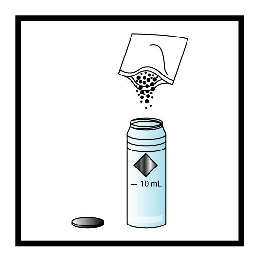
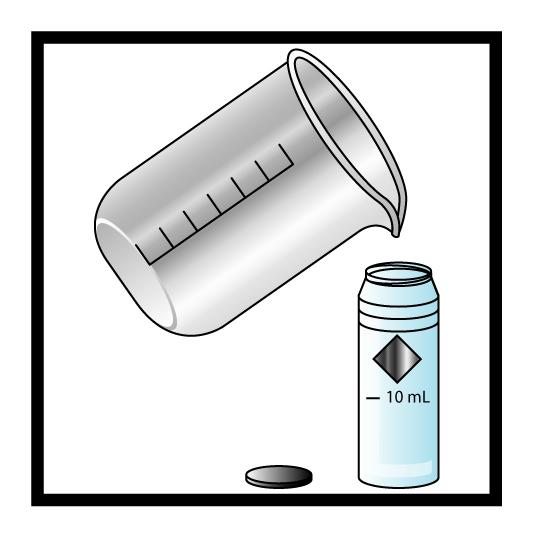
Chlorine Procedures DPD Spectrophotometric ©2017, Texas A&M Engineering Extens ion Service. All rights reserved. PM B - 11
Figure B.1: 10-mL sample cell
Figure B.2: Chlorine powder pillow action
3.Time: A three-minute reaction period will begin. Perform steps 4 and 5 during this time period (FigureB.3).

4.Fill another round sample cell with 10 mL of sample. (This is the blank.) Wipe the sample cell and place it into the cell holder (FigureB.4).
5.Touch Zero. The display will show: 0.00 mg/L Cl2.
Chlorine Procedures DPD Spectrophotometric ©2017, Texas A&M Engineering Extens ion Service. All rights reserved. PM B - 12
Figure B.3: Three-minute reaction period
Figure B.4: 10-mL sample cell
6.Within three minutes after the timer beep, wipe the prepared sample and place it into the cell holder. Results will appear in mg/L Cl2 (FigureB.5).
7.Repeat the above procedures this time utilizing the DPD Free Chlorine Pillow. You will not have to wait the three-minute reaction time for free chlorine, mix as described and place in analyzer and press read.
Quality Assurance/Quality Control
30 TAC §290.46: Minimum Acceptable Operating Practices for Public Drinking Water Systems
(2) Laboratory equipment used for compliance testing shall be properly calibrated.
(C) Disinfectant residual analyzers shall be properly calibrated.
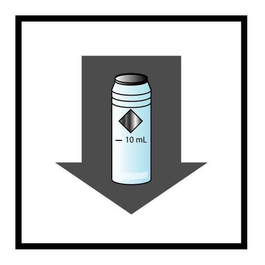
(i)The accuracy of manual disinfectant residual analyzers shall be verified at least once every 30 days using chlorine solutions of known concentrations.
(ii)Continuous disinfectant residual analyzers shall be calibrated at least once every 90 days using chlorine solutions of known concentrations.
Chlorine Procedures DPD Spectrophotometric ©2017, Texas A&M Engineering Extens ion Service. All rights reserved. PM B - 13
Figure B.5: Place sample in cell holder
Chlorine Procedures
DPD Spectrophotometric
(iii)The calibration of continuous disinfectant residual analyzers shall be checked at least once each month with a chlorine solution of known concentration or by comparing the results from the on-line analyzer with the result of approved benchtop amperometric, spectrophotometric, or titration method.
The Pocket-Colorimeter from HACH is classified as a spectrophotometric analyzer.
©2017, Texas A&M Engineering Extens ion Service. All rights reserved.
PM B - 14
©2017, Texas A&M Engineering Extens ion Service. All rights reserved. Appendix
Water Operator Licensing Rules and Testing Information
Water Operator Licensing Rules and Testing Information ©2017, Texas A&M Engineering Extens ion Service. All rights reserved. PM C - 2
Water Operator Licensing Rules
Texas Commission on Environmental Quality Page 1
Chapter 30 - Occupational Licenses and Registrations
SUBCHAPTER K: PUBLIC WATER SYSTEM OPERATORS AND OPERATIONS COMPANIES
§§30.381, 30.387, 30.390, 30.392, 30.396, 30.398, 30.400, 30.402
Effective September 29, 2016
§30.381. Purpose and Applicability.
(a) The purpose of this subchapter is to establish qualifications for issuing and renewing licenses and registrations to:
(1) public water system operators who perform process control duties in production or distribution of drinking water; and
(2) operations companies that operate public water systems on a contractual basis.
(b) A person who performs any of the tasks listed in subsection (a) of this section must meet the qualifications of this subchapter and be licensed or registered according to Subchapter A of this chapter (relating to Administration of Occupational Licenses and Registrations), unless exempt under §30.402 of this title (relating to Exemptions); and must comply with the requirements in Chapter 290 of this title (relating to Public Drinking Water).
(c) Public water system operator licenses, certificates of competency, and registrations issued before January 1, 2002, remain in effect until they expire, or are replaced, or revoked by the commission.
(d) Renewable Class D licenses, previously issued to individuals who did not possess a high school diploma or equivalent certificate may be renewed according to §30.392 of this title (relating to Qualifications for License Renewal).
(e) An individual that is issued a license under this subchapter must perform adequate process control duties as recognized by current best management practices.
(f) An individual who has an honorary license shall not perform process control duties in production or distribution of drinking water for a public water system.
Adopted September 5, 2007
Effective September 27, 2007
Water Operator Licensing Rules and Testing Information Water Operator Licensing Rules
Texas A&M Engineering Extens ion Service. All rights reserved. PM C - 3
©2017,
Water Operator Licensing Rules and Testing Information Water Operator Licensing Rules
Texas Commission on Environmental Quality Page 2
Chapter 30 - Occupational Licenses and Registrations
§30.387. Definitions.
The following words and terms, when used in this subchapter, shall have the following meanings, unless the context clearly indicates otherwise.
(1) Chief operator--An individual who has overall responsibility for the operation of a public water system.
(2) Honorary license--License converted from a perpetual license that has been discontinued by the commission. This honorary license does not award the licensee the authority to perform process control duties in production or distribution of drinking water for public water systems.
(3) Military operator-in-training--An individual who is an active duty member of the military of the United States and has successfully completed the Bioenvironmental Engineering Apprentice (BEA) or equivalent military training, as determined by the executive director, and collects microbiological samples and determines disinfection residuals for military facilities' water distribution systems. This individual may not perform any other process control duties in the water distribution or treatment facilities of a military installation.
(4) Operator-in-charge--An individual who has overall responsibility for the operation of a public water system in the absence of the chief operator.
(5) Operator-in-training--An unlicensed individual entering the field of public water system operation for the first time who has less than one year of experience and is in training to perform process control duties in production or distribution of public drinking water.
(6) Public water system operations company--A person or other nongovernmental entity that provides operations services to one or more public water systems on a contractual basis.
(7) Public water system operator--Licensed operator who performs process control duties in production or distribution of drinking water.
(8) Work experience--The actual performance of job tasks in a public water supply system that are considered essential for the treatment or distribution of drinking water.
Adopted December 5, 2012
Effective December 27, 2012
Texas A&M Engineering Extens ion Service. All rights reserved. PM C - 4
©2017,
Texas Commission on Environmental Quality
Chapter 30 - Occupational Licenses and Registrations
§30.390. Qualifications for Initial License.
(a) To obtain a license, an individual must meet the requirements of Subchapter A of this chapter (relating to Administration of Occupational Licenses and Registrations), and the following requirements for each class of license, and pass an examination.
(b) An individual who applies for a Class C, B, or A license, and relies on a bachelor's or master's degree to meet the educational requirements, must have a bachelor's or master's degree with a major in chemistry, biology, engineering, microbiology, bacteriology, or other similar discipline approved by the executive director.
(c) An individual who applies for a Class C or B license must obtain at least one-half of the total work experience requirement in the specific field for the license that is requested:
Water Operator Licensing Rules and Testing Information Water Operator Licensing Rules ©2017, Texas A&M Engineering Extens ion Service. All rights reserved. PM C - 5
Page 3
License Education Work Experience Training Credits Class D High School Diploma (HSD) or equivalent None 20 hours Class C, Distribution, Groundwater, Surface water HSD or equivalent 2 years 60 hours Class B, Distribution and Groundwater Bachelor's HSD or equivalent 2½ years 5 years 120 hours 120 hours Class B, Surface water Bachelor's HSD or equivalent 2½ years 5 years 144 hours 144 hours Class A Master's Bachelor's HSD or equivalent 4 years 5 years 8 years 184 hours 184 hours 184 hours
Figure: 30 TAC §30.390(a)
Water Operator Licensing Rules and Testing Information Water Operator Licensing Rules
Texas Commission on Environmental Quality Page 4
Chapter 30 - Occupational Licenses and Registrations
(1) for Class C and B surface water licenses, the experience must be obtained through operations activities at the production or treatment facilities for surface water or groundwater under the direct influence of surface water;
(2) for Class C and B groundwater licenses, the experience must be obtained through operations activities at the production or treatment facilities for groundwater source or groundwater under the direct influence of surface water; or
(3) for Class C and B distribution licenses, at least one-half of the required experience must be obtained as a result of operations activities at treated water storage, pumping, or distribution facilities; and
(4) once the work experience has been met from paragraphs (1), (2), or (3) of this subsection, the executive director may count any remaining experience to meet up to 50% of the remaining requirement.
(d) For all classes of licenses, laboratory experience must:
(1) be obtained at a laboratory that is owned and operated by the public water system; and
(2) involve daily consultation with individuals who perform process control duties in production or distribution of drinking water for the water system.
(e) For each license, applicants may substitute either college hours or training credits to meet the experience requirement:
(1) 16 semester hours or an additional 20 hours of training credits are equal to six months of the experience;
(2) Class C applicants may only substitute up to one year of the required work experience; and
(3) Class B and Class A applicants may only substitute up to two years of the required work experience.
(f) Training credits must be in approved courses that include the following or equivalent.
©2017, Texas A&M Engineering Extens ion Service. All rights reserved. PM C - 6
License
Elective Training Courses Class D Basic Waterworks Operation None
Figure: 30 TAC §30.390(f)
Core Training Courses
Texas Commission on Environmental Quality
Chapter 30 - Occupational Licenses and Registrations
Basic Waterworks Operation
Class C
Surface Water
Surface Water Production I
Surface Water Production II
Water Operator Licensing Rules
Page 5
Class C
Groundwater
Basic Waterworks Operation
Groundwater Production
Plus one elective course
None
Water Distribution
Water Laboratory
Water Utility Safety
Water Utility Calculations
Chlorinator Maintenance
Pump and Motor
Maintenance
Valve and Hydrant
Maintenance
Water Laboratory
Water Utility Safety
Water Utility Calculations
Class C
Water Distribution
Basic Waterworks Operation
Water Distribution
Plus one elective course
Chlorinator Maintenance
Pump and Motor
Maintenance
Valve and Hydrant Maintenance.
Class B
Surface Water
Basic Waterworks Operation
Surface Water Production I
Surface Water Production II
Water Distribution
Water Utility Safety
Water Laboratory
Water Utility Management
Basic Waterworks Operation
Groundwater Production
Water Laboratory
Class B
Groundwater
None
Class B
Water Distribution
Water Distribution
Water Utility Safety
Plus one elective course
Basic Waterworks Operation
Water Distribution
Water Utility Safety
Pump and Motor
Maintenance
Valve and Hydrant
Water Utility Management
Water Utility Calculations
Chlorinator Maintenance
Pump and Motor
Maintenance
Valve and Hydrant Maintenance
Water Utility Management
Water Utility Calculations
Chlorinator Maintenance
Water Laboratory
Water Operator Licensing Rules and Testing Information
Texas A&M Engineering Extens ion Service. All rights reserved. PM C - 7
©2017,
Water Operator Licensing Rules and Testing Information
Water Operator Licensing Rules
Texas Commission on Environmental Quality
Chapter 30 - Occupational Licenses and Registrations
Maintenance
Plus one elective course
Basic Waterworks Operation
Surface Water Production I
Surface Water Production II
Groundwater Production
Class A
Water Distribution
Water Laboratory
Water Utility Management
Water Utility Safety
Page 6
Plus additional training to meet the 184 hour requirement
(g) An individual who previously held a Class D license shall not apply for a new Class D license if the individual:
(1) currently operates facilities at groundwater treatment systems of 250 connections or more;
(2) currently operates facilities at groundwater treatment systems serving a population of 750 or more;
(3) currently operates facilities at surface water treatment systems;
(4) currently operates facilities at groundwater systems under the influence of surface water;
(5) performs supervisor, crew chief, or foremen duties for distribution systems that have over 250 connections; or
(6) operates multiple groundwater systems and the cumulative number of connections exceeds 250.
Adopted September 7, 2016
§30.392. Qualifications for License Renewal.
(a) To renew a license, an individual must have:
Effective September 29, 2016
(1) met the requirements of Subchapter A of this chapter (relating to Administration of Occupational Licenses and Registrations) and completed a total amount of approved continuing education equal to that of ten hours per year the license is valid; or
©2017,
A&M Engineering Extens ion Service. All rights reserved. PM C - 8
Texas
Texas Commission on Environmental Quality
Chapter 30 - Occupational Licenses and Registrations
Page 7
(2) met the requirements of Subchapter A of this chapter and passed the examination for the license.
(b) The basic water training course shall not be used to renew a Class B or A license.
(c) Class D licenses are not renewable for licensed operators:
(1) at groundwater treatment systems of 250 connections or more;
(2) at groundwater treatment systems serving a population of 750 or more;
(3) at surface water treatment systems;
(4) at groundwater systems under the influence of surface water;
(5) who are supervisors, crew chiefs, or foremen of distribution systems that have over 250 connections; or
(6) who operate multiple groundwater systems and the cumulative number of connections exceeds 250.
(d) To renew an active converted perpetual license, an individual must have met the requirements of this section, with the exception of the renewal fee.
Adopted September 5, 2007
§30.396.
Qualifications for Initial Registration.
Effective September 27, 2007
To obtain a registration, a person must meet the requirements of Subchapter A of this chapter (relating to Administration of Occupational Licenses and Registrations).
Adopted November 20, 2001
§30.398.
Qualifications for Registration Renewal.
Effective December 17, 2001
To renew a registration a person must meet the requirements of Subchapter A of this chapter (relating to Administration of Occupational Licenses and Registrations).
Adopted November 20, 2001
Effective December 17, 2001
Water Operator Licensing Rules and Testing Information Water Operator Licensing Rules ©2017, Texas A&M Engineering Extens ion Service. All rights reserved. PM C - 9
Water Operator Licensing Rules and Testing Information Water Operator Licensing Rules
Texas Commission on Environmental Quality Page 8
§30.400. Additional Requirements for Public Water System Operations Companies.
(a) When a public water system operating company submits an application to obtain or renew a registration, it must submit a report to the executive director. The report shall include:
(1) the public water system operating company name, registration number, location, and mailing address;
(2) the public water system identification number and name for each system operated;
(3) the dates of operation during the reporting period;
(4) the names and license numbers of all licensed operators employed by the operations company;
(5) the names of the licensed chief operators and licensed supervisors; and
(6) any additional information required by the executive director.
(b) A person that operates a public water system under contract must apply for a new registration and submit an amended report if a company is bought or sold and the name of the company changes.
(c) Public water system operating companies shall submit a registration fee based on the number of public water systems served as indicated in the following table.
©2017, Texas A&M Engineering Extens ion Service. All rights reserved. PM C - 10
Chapter 30 - Occupational Licenses and Registrations
Number of Public Water Systems Served Fee 0 to 4 $122 5 to 9 $240
Figure: 30 TAC §30.400(c)
Texas Commission on Environmental Quality
Chapter 30 - Occupational Licenses and Registrations
10 to 19 $399
20 or more
Adopted September 5, 2007
§30.402. Exemptions.
$636
Page 9
Effective September 27, 2007
(a) An individual who performs process control duties in production or distribution of drinking water for a transient non-community water system as defined in §290.38(77) of this title (relating to Definitions), is exempt from the licensing requirements of this subchapter, if the source water for the water system is purchased treated water or groundwater that is not under the direct influence of surface water.
(b) An operator-in-training under the direct supervision of a licensed public water system operator is exempt from the licensing requirements of this subchapter.
(c) A military operator-in-training under the direct supervision of a licensed public water system operator is exempt from the licensing requirements of this subchapter for the purpose of collecting microbiological samples or determining disinfection residuals at military facilities’ water distribution systems. The military operator-in-training is not exempt from the licensing requirements of this subchapter for the purpose of performing any other process control duties in the distribution or treatment facilities of a public water system.
(d) An individual who holds a groundwater or surface water license may perform duties relating to the operation and maintenance of drinking water production, purchased water, and water distribution systems and is not required to hold a distribution license.
Adopted December 5, 2012
Effective December 27, 2012
Licensing Rules and Testing Information Water Operator Licensing Rules
Texas A&M Engineering Extens ion Service. All rights reserved. PM C - 11
Water Operator
©2017,
Water Operator Licensing Rules and Testing Information
Water Operator Licensing Rules
Engineering Extens ion Service. All
PM C - 12
©2017, Texas A&M
rights reserved.
TCEQ Testing
Beginning September 1, 2016, the TCEQ is planning to initiate a preapproval process for all new license applications. This process will be similar to the process already used for preapproving “A” Water or Wastewater license applications and CBT applications. This means that new license applicants will not be eligible to register for an exam until their application is administratively complete, approved by the TCEQ, and they receive a letter from the TCEQ notifying them they are eligible to register for an exam session.
Water Operator Licensing Rules and Testing Information TCEQ Testing ©2017, Texas A&M Engineering Extens ion Service. All rights reserved. PM C - 13
TCEQ Test Locations and Dates
Texas Commission on Environmental Quality
MC-178 P.O. Box 13087 Austin, Texas 78711-3087
Exam Schedules
https://www.tceq.texas.gov/licensing/exams/registration
Exam Results and Training Records
https://www.tceq.texas.gov/licensing
TCEQ licensing exams are administered at the central and regional offices on a monthly basis. To take an exam, you must register online (see above website) for an available seat and pay your application fee via the TCEQ ePay system.
Exam results should be posted on the website within four weeks of your exam date and mailed to you within six weeks of your exam date. To ensure timely processing, please do not call the TCEQ for exam results unless it has been over six weeks since your exam date.
Exam sessions administered in the TCEQ Regional Offices may be cancelled during holidays and during the months coinciding with regional conferences scheduled in their area.
Please contact your Regional Office to confirm scheduled exam dates and times and please arrive at your designated exam site on time as scheduled.
What to bring to the exam site: No. 2 pencils, your employment history, copies of training course completion certificates or cards, copies of college transcripts, non-programmable calculator, and a photo I.D. card (driver’s license). Note: Cell phone usage is not permitted in the examination room (including the calculator function).
To request special accommodations in compliance with the Americans with Disabilities Act, please contact the Austin Central Office at 512/239-6133.
TCEQ Testing ©2017, Texas A&M Engineering Extens ion Service. All rights reserved. PM C - 14
Water Operator Licensing Rules and Testing Information
Computer-Based Testing for Occupational Licenses

Take your license examination on a computer!
CBT license examinations offer:
• The convenience of numerous CBT exam sites
• Daily access and expanded hours to CBT exam sites
• Immediate exam score with e-mail option
• Immediate printed exam analysis feedback with e-mail option
• License issued to applicants passing CBT exam within one week of exam date
• Immediate retesting, if the exam site has available seating (4 attempts per application)
• User-friendly computer screens
Examinations available for CBT by Licensing Program
Customer Service Inspectors
Landscape Irrigation
Landscape Irrigation Inspector
Landscape Irrigation Technician (English Only)
Municipal Solid Waste Facility Supervisors
Class A
Class B
On-site Sewage Facility (OSSF)
OSSF Maintenance Provider
Wastewater Treatment and Collection System Operators
Class I Wastewater Collection System Operator
Class B
Class C
Wastewater Treatment Facility Operator
Wastewater Treatment Facility Operator
Class D Wastewater Treatment Facility Operator
Water Operator Licensing Rules and Testing Information TCEQ Testing ©2017, Texas A&M Engineering Extens ion Service. All rights reserved. PM C - 15
Water Treatment and Distribution System Operators
Class B Groundwater Operator
Class B Surface Water Operator
Class B Water Distribution
Class C Groundwater Operator
Class C Surface Water Operator
Class C Water Distribution
Class D Water
Water Treatment Specialists
Class III
Class II
Class I
Pre-approval of your licensing application is required. For preapproval, applicants must:
o complete license requirements— education experience training
o submit an application with the $111 processing fee to TCEQ Occupational Licensing, MC-178, PO Box 13087, Austin, TX 78711-3087
o To obtain an application, go to the CBT Application Request Form and submit your request. An application packet will be mailed to you upon receipt of your request.
Upon receiving an approval letter, the applicant will need to:
o make an appointment with a registered Test Center to take the exam
o pay a nominal fee to the Test Center
Retesting by CBT after failing a written test is allowed, so long as your application is in an approved status.
TCEQ Testing ©2017, Texas A&M Engineering Extens ion Service. All rights reserved. PM C - 16
Water Operator Licensing Rules and Testing Information
Registered Computer-Based Testing Centers
Contact each testing location to schedule a CBT exam.
City Test Center Location
Amarillo Amarillo College Student Service Center, 101 2201 South Washington Amarillo, Texas
Arlington North Central Texas Council of Governments
Classroom A 624 Six Flags Drive, Ste 125
Austin Austin Community College Visit the ACC website to view testing locations
Brownsville
The University of Texas at Brownsville
Bryan Texas A & M Engineering Extension Service
Fort Worth Tarrant County College
UTB Office of Testing 1601 E. Price Rd,Ste. E Brownsville, TX 78520
TAMU Riverside Campus, Bldg 8004 3100 State Hwy 47 Bryan, TX 77807
Northwest Campus WCTS-1133 4801 Marine Creek Pkwy Fort Worth, TX 76179
Galveston Galveston College 4015 Avenue Q Galveston, TX 77550
Houston Houston Community College 1300 B Holman St, RM 211 Houston, TX 77004
Houston Texas Southern University
Roderick Paige Building Basement Level, RM 007 3100 Cleburne St Houston, TX 77004
Contact Information
Website: Amarillo Testing Center
Email: acproctor@actx.edu
Phone: 806-371-5445
Website: NCTCOG Testing Center
Email: NCTCOGTraining@nctcog.org
Phone: 817-608-2310
Website: ACC Testing Center
Email: bact@austincc.edu
Phone: 512-223-7395
Website: UTB Testing Center
Email: testing@utb.edu
Phone: 956-882-7084
Website: Email: Phone: 800-723-3811
Website: TCC Testing Center
Email: ProfessionalTesting@tccd.edu
Phone: 817-515-7653
Website: GC Testing Center
Email: mmackey@gc.edu
Phone: 409-944-1290
Website: HCC Testing Center
Email: ce.testing@hccs.edu
Phone: 713-718-6012
Website: TSU Testing Center
Email: testing@tsu.edu
Phone: 713-313-7387
Huntsville Sam Houston State University
Huntsville Campus 1921 Avenue J Academic Building IV, RM 102 Huntsville, TX 77340
Website: SHU Testing Center
Huntsville Testing Center
Email: test.ctr@shsu.edu
Phone: 936-294-1025
©2017, Texas A&M Engineering Extens ion Service. All rights reserved.
Water Operator Licensing Rules and Testing Information TCEQ Testing
PM C - 17
Water Operator Licensing Rules and Testing Information
Killeen Central Texas College
Nacogdoches Stephen F. Austin University
6200 W Central Texas Expressway Killeen, TX 76549
Rusk Bldg, RM 328 1936 North St Nacogdoches, TX 75962
San Antonio Alamo Colleges –San Antonio College
San Antonio College Assessment / Testing Center Fletcher Administrative Center Bldg. #112 (FAC #112) 1819 N. Main Ave San Antonio, TX 78212
Texarkana Texarkana College Palmer Memorial Library 2500 North Robison Rd Texarkana, TX 75599
Texas City College of the Mainland Enrollment Center A-126 1200 Amburn Rd Texas City, TX 77591
The Woodlands Sam Houston State University
The Woodlands Center 3380 College Park Dr. Ste. 303 The Woodlands, TX 77384
Victoria The University of Houston at Victoria 3007 N. Ben Wilson Victoria, TX 77901
Weatherford Weatherford College Jack Knight Building 225 College Park Dr Weatherford, TX 76086
Wichita Falls Midwestern State University Hardin Admin. Bldg. RM 224 3410 Taft Blvd Wichita Falls, TX 76308
Keep
Website: College of Mainland Testing Center
Email: joanna.johnson@ctcd.edu
Phone: 254-526-1520
Website: SFA Testing Center
Email: sfatesting@sfasu.edu
Phone: 936-468-3958
Download Additional Information for Registration (PDF): http://www.alamo.edu/WorkArea/Do wnloadAsset.aspx?id=51227 Contact: Oscar C. San Miguel
Email: osan@alamo.edu
Phone: 210-486-0446
Website: TC Testing Center
Email: texarkanacollege.edu/forms/email/ Phone: 903-823-3278
Website: Central Texas Testing Center
Email: testingcenter@com.edu
Phone: 409-933-8676
Website: SHU Testing Center
The Woodlands Testing Center
Email: test.ctr@shsu.edu
Phone: 936-294-1025
Website: UHV Testing Center
Email: testing@uhv.edu
Phone: 361-570-4285
Website: Weatherford Testing Center
Email: testing@wc.edu
Phone: 817-598-6383
Website: MSU Testing Center
Email: lynn.ducioame@mwsu.edu
Phone: 940-397-4676
©2017, Texas A&M Engineering Extens ion Service. All rights reserved.
TCEQ Testing
PM C - 18
checking this webpage for updates and additions to the list of registered CBT sites.
Course Final Exam
©2017, Texas A&M Engineering Extens ion Service. All rights reserved. Appendix
Course Final Exam ©2017, Texas A&M Engineering Extens ion Service. All rights reserved. PM D - 2
1.In Texas, water operator licensing is administered by the ________.
a.EPA
b.TEEX
c.TCEQ
d.OSHA
2.Which minerals cause hardness in water?
a.calcium and manganese
b.nitrates and phosphates
c.magnesium and calcium
d.iron and magnesium
3.The most important federal law impacting the water utility industry is the ________.
a.Water Resources Development Act
b.Hazard Communication Act
c.Federal Water Pollution Control Act
d.Safe Drinking Water Act
4.The four water quality standards established for drinking water in the Safe Drinking Water Act are chemical, bacteriological, radiological, and ________.
a.mineral
b.physical
c.thermal
d.taste and odor
e.organic/inorganic
5.The minimum allowable pressure in the distribution system under emergency conditions is ________.
a.35 psi
b.20 psi
c.30 psi
d.none listed
Course Final Exam ©2017, Texas A&M Engineering Extens ion Service. All rights reserved. PM D - 3
6.Water vapor given off by plants and trees is known as ________.
a.precipitation
b.transportation
c.evaporation
d.transpiration
7.Organic matter includes ________.
a.leaves, beavers, birds, clay
b.wood, fish, algae, sand
c.wood, dogs, algae, and bacteria
d.plants, animals, humans, minerals
8.The single most important water treatment process is ________:
a.coagulation, sedimentation, and filtration
b.taste and odor removal
c.disinfection
d.fluoridation
9.Excessive nitrates in drinking water can cause ________ syndrome in infants.
a.bad baby
b.bloody baby
c.blue body
d.blue baby
10.A sanitary control easement must cover land within ________ feet of a public water well.
11.A sample for physical and chemical analysis of a new well must be taken after ________ hours of continuous pumping.
Course Final Exam ©2017, Texas A&M Engineering Extens ion Service. All rights reserved. PM D - 4
a.50 b.150 c.500 d.100
c.20 d.30
a.24 b.36
12.Chapter 290 Rules and Regulations requires chemical analysis of surface water supplies every ________.
a.three years
b.six months
c.year
d.both a and c
13.Detention time in sedimentation basins must be at least ________ hours to allow floc to settle. a.6 b.4 c.5
d.3
14.Backwashing should expand the filter media by ________ percent.
a.30 to 60
b.25 to 30
c.15 to 20
d.30 to 50
15.In Texas, all public water systems are required to have ________ facilities.
a.ozonation
b.softening
c.chlorination
d.trihalomethane
16.The MCL for Trihalomethanes in drinking water is ________.
a.0.060 mg/L
b.0.6 mg/L
c.0.080 mg/L
d.0.8 mg/L
Course Final Exam ©2017, Texas A&M Engineering Extens ion Service. All rights reserved. PM D - 5
17.At room temperature chlorine gas is greenish-yellow, has a pungent odor, is ________ times heavier than air.
a.2
b.2 1/2
c.1 1/2
d.3
18.Diseases that may be spread by inadequately disinfected water are ________.
a.typhoid, cholera, dysentery, flu
b.hepatitis A, polio, gastroenteritis, measles
c.typhoid, cholera, infectious hepatitis, legionnaires disease
d.dysentery, cholera, cancer, polio
e.all the above
19.Minimum chlorine residuals of ________ (free) and ________ (combined) are required in the far reaches of the distribution system.
a..5/0.2
b.2/5
c.5/2
d.0.2/0.5
20.Parameters that affect coagulation are ________.
a.turbidity
b.pH and alkalinity
c.coagulant and dosage
d.all the above
e.none of the above
21.Do not work in a trench ________ feet or deeper unless it is protected from cave-in. a.7 b.5 c.6 d.3
Course Final Exam ©2017, Texas A&M Engineering Extens ion Service. All rights reserved. PM D - 6
22.Place spoil banks at least________ feet from the edge of the excavation.
a.4
b.2
c.3
d.1
23.Dose new water mains with a minimum ________mg/L or more of chlorine at least every ________ hours.
a.25/24
b.500/24
c.50/6
d.200/1
24.One bacteriological sample is required for each ________ of new completed main.
a.10,000 feet
b.mile
c.1,000 yards
d.1,000 feet
25.A cross connection is a physical connection between a public water supply and 1) another supply of unknown or questionable quality, 2) any source that may contain contamination,
3)any water ________.
a.safe to drink
b.treated to a greater degree
c.treated to potable quality
d.treated to a lesser degree
26.Maximum spacing between ladders in a trench is ________.
a.25 feet
b.50 feet
c.75 feet
d.there is no such requirement
Course Final Exam ©2017, Texas A&M Engineering Extens ion Service. All rights reserved. PM D - 7
27.When should a rapid sand filter be backwashed?
a.when it gets dirty
b.when water will no longer pass through the filter
c.loss of head of 6 to 10 feet
d.turbidity readings higher than 0.5 NTU
e.all listed
28.A ditch 4 feet wide, 6 feet deep, and 1,000 feet long will be excavated. How many cubic yards of pipe bedding will be needed to bed the trench 7 inches deep?
a.86
b.2,320
c.23,200
d.860
29.How many gallons will 5,000 feet of 18-inch water pipe hold?
a.41,600 gallons
b.58,500 gallons
c.62,000 gallons
d.66,100 gallons
30.A tank that has a capacity of 700,000 gallons must be disinfected with a dosage of 50 mg/L of chlorine. How much 65% HTH will it take to achieve the same goal?
a.292 pounds
b.356 pounds
c.449 pounds
d.552 pounds
Course Final Exam ©2017, Texas A&M Engineering Extens ion Service. All rights reserved. PM D - 8
Your feedback is important to us!
TEEXisdedicatedtoservingtheneedsofitscustomers,andproducingqualitycurriculum, classroommaterials,andpublicationsthatcontainaccurateandup-to-datecontent.Our materialsarereviewedregularlyforaccuracy,editorialquality,andpublicationstandards.
AsaTEEXcustomer,youshouldexpectustomaintainourcommitmenttoexcellence. If youhaveasuggestiontohelpusensurethequalityofourproducts,pleasecompletethe requestedinformationbelow,detachthisformfromthemanual,andsendyourcomments toususingthispageasatri-foldmailer(seereverse).
WWW001
Comments:(Pleasereferencepagenumberandparagraph)
Ifyouwouldlikeustocontactyouregardingyourcomments,pleasecompletethe followinginformation.
Yes,pleasecontactme! ________No,don’tcontactme.
Name: ________________________________________________ PhoneNumber: ____________________________
Email:_______________
MailingAddress:_____________________________________________________________________________________
TrainingManager
Water&EnvironmentalProgram
InfrastructureTraining&SafetyInstitute
P.O.Box40006 CollegeStation,TX77842-4006
Fold here Fold here
Place Stamp Here
Basic Mathematics
Constants, Equivalents, and Conversion Factors
1 cu ft of water = 7.48 gallons
1 cu ft of water = 62.4 lbs
1 gallon = 231 cu in
8.34 lb = one part per million by weight of one million gallons of water
325,851 gal per acre foot
Gal/min ÷ 448.8 = ft3/sec
MGD = million gallons per day (mgd)
SG = specific gravity of a liquid
Formulas
Area of a rectangle = a x b
Area of a triangle = ½ (a x b)
Area of a trapezoid = ½ (a + b) h
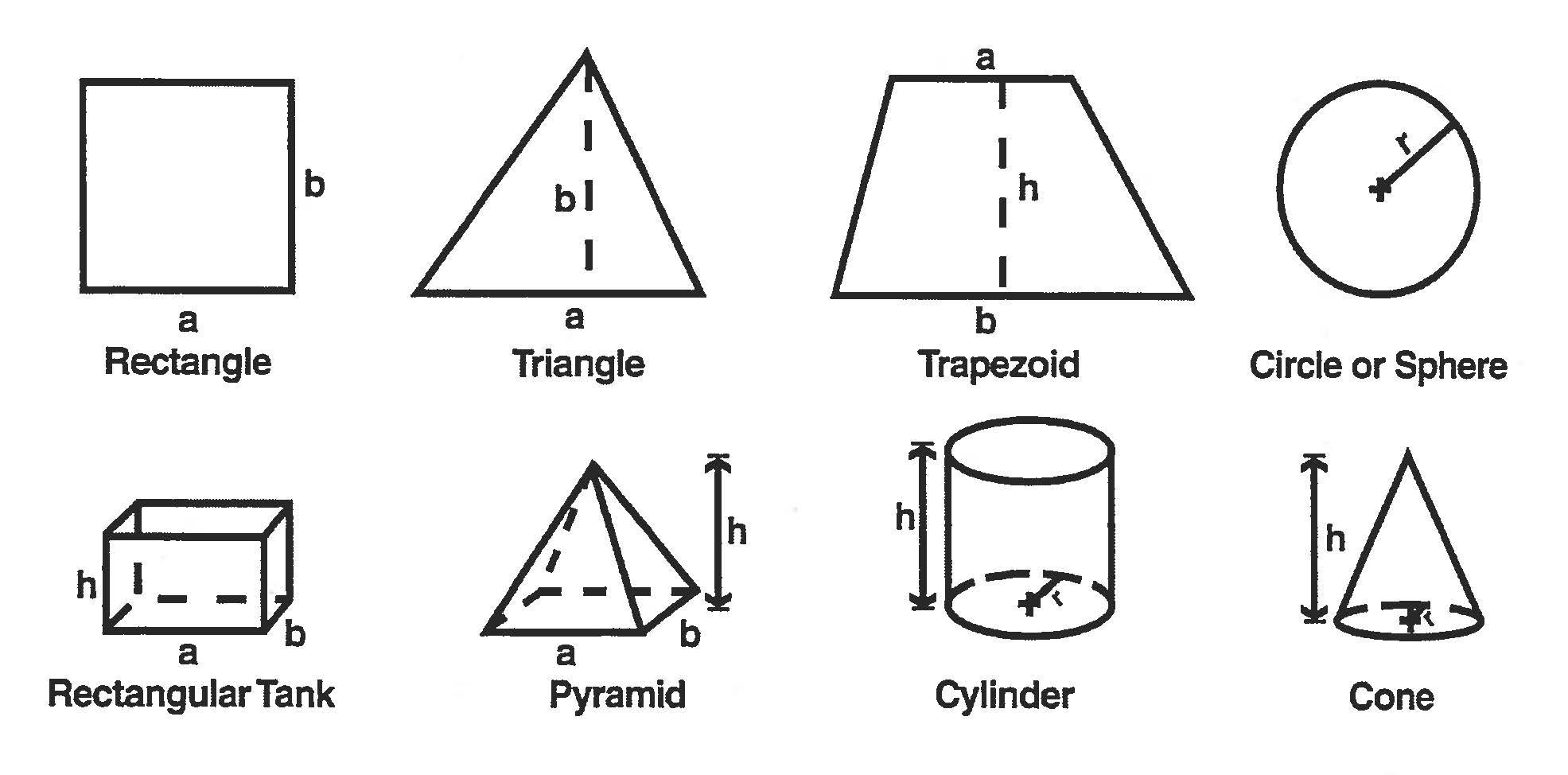
Area of a circle = πr 2
Circumference of a circle = 2πr
Volume of a rectangular tank = a x b x h
Volume of a pyramid = ⅓(a x b x h)
Volume of a cylinder = πr2h
Volume of a cone = ⅓(πr2h)
Volume of a sphere = 4/3(πr3)
Volume of a trapezoidal channel = ½ (a + b) x h x length
Diagrams
Π (pi) use 3.14
1 HP = 0.747 kilowatts = 33,000 ft-lb/minute
1 kilowatt – 1.34 HP
1 psi = 2.31 ft
1 mile = 5,280 ft
43,560 sq ft = 1 acre
1 day = 1,440 minutes
1 gpg = 17.1 mg/L
Flow: Q = AV, V = velocity
Detention time = V/Q, V = volume
Horsepower: HP = . ,
Lbs/day = (MGD)(mg/L)(8.34)
Dosage in mg/L = .
V1N1 = V2N2
CONTACTS Infrastructure & Safety Environmental/Irrigation Water/Wastewater Safety and Health Transportation Electric Power Heavy Equipment Telecommunications Confined Space Operations 800. 723.3811 ITSI@t eex.tamu.edu Law Enforcement & Security Law Enforcement Extension Forensic Science Academy Basic Police Academy Emergency Driving Private Security Explosives Corrections Academy Infrastructure Protection Accident Reconstruction 80 0.423.8433 Law @teex.tamu.edu Fire & Rescue Industrial/Municipal Firefighting Incident Management Hazardous Materials Rescue Training Leadership Technical Assistance Fire Recruit Academy Emergency Medical Services 866.878.8900 E STI@teex.tamu.edu Economic & Workforce Development Product Development and Testing Therapeutics Manufacturing Economic Development Cybersecurity Market Intelligence Manufacturing Assistance Training Software Products 800.541.7149 K E@teex.tamu.edu Mailing Address P.O. Box 40006 College Station, TX 77842-4006 Texas A&M Engineering Extension Service Headquarters 200 Technology Way College Station, TX 77845-3424 Texas A&M Engineering Extension Service Toll-Free 877.833.9638 Phone 979.458.6805 Fax 979.458.6822


I nfrastructure & s afety f I re & r escue L aw e nforcement & s ecur I ty e conom I c & w orkforce D eve L opment
