Chapter 2
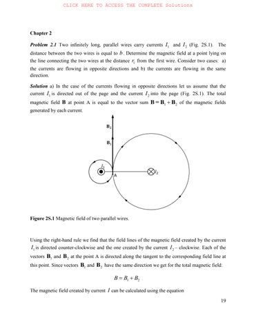
Problem 2.1 Two infinitely long, parallel wires carry currents 1I and 2I (Fig. 2S.1). The distance between the two wires is equal to b. Determine the magnetic field at a point lying on the line connecting the two wires at the distance 1r from the first wire. Consider two cases: a) the currents are flowing in opposite directions and b) the currents are flowing in the same direction.
Solution a) In the case of the currents flowing in opposite directions let us assume that the current 1I is directed out of the page and the current 2I into the page (Fig. 2S.1). The total magnetic field B at point А is equal to the vector sum 12 BBB = of the magnetic fields generated by each current.

Figure 2S.1 Magnetic field of two parallel wires.
Using the right-hand rule we find that the field lines of the magnetic field created by the current 1I is directed counter-clockwise and the one created by the current 2I – clockwise. Each of the vectors 1B and 2B at the point А is directed along the tangent to the corresponding field line at this point. Since vectors 1B and 2B have the same direction we get for the total magnetic field:
The magnetic field created by current I can be calculated using the equation
r
, where 0μ is permeability of free space, m is magnetic permeability of the medium where the wire is immersed, and r is the distance from the wire to the point where the magnetic field is determined. Therefore,
For the magnetic field intensity we get the following expressions:
b) In the case of the currents directed in the same direction we get:
As the magnitude of the magnetic field and the magnetic field intensity are determined by the difference of contributions from each wire, the direction of total vectors В and В in this case must coincide with the direction of the largest iВ and correspondently iH that are determined by the largest magnitude 11 / Ir or 21/()Ibr in the above equations.
Problem 2.2 A long thin conductor is bent as shown in Fig. 2S.2. The coil in the 0 xz plane consists of three quarters of a full circle of radius R . The conductor carries a current I . Find the vector B and its magnitude at the center O of the coil, assume that the coil is in vacuum.
Solution The current in the coil generates the magnetic field whose vector at the center of the coil (point O) is directed along the y -axis and its magnitude is equal to 3/4 of the value of Eq. (2.14) of the text:
Each of the semi-infinite straight wires with current I generates at the point O a magnetic field of magnitude:
Figure 2S.2 Magnetic field of three quarters of a circle of radius R
The upper part of the wire (lies in O xy -plane) will create at the point O a magnetic field directed along the negative z -axis. Therefore, at point O there is a z -component of the magnetic field:
The lower part of the wire (lies in the O yz -plane) generates at point O a magnetic field directed along the negative x -axis. Therefore, at point O there is an x -component of magnetic field:
Thus, the net magnetic field vector is equal to:
where , ij and k are unit vectors
The magnitude of the field is: 2 00 3 4241()14.92.
Problem 2.3 A charged particle moves with constant velocity
62.0010 m/s v in a uniform magnetic field 0.50 T B on a circular orbit whose plane is perpendicular to the magnetic field. The radius of the orbit is equal to 2.00cm R and the kinetic energy of the particle
42.0010 eV W . Determine: a) the charge of the particle, b) the potential difference which accelerates the particle from rest to 62.0010 m/s v before entering into the magnetic field, and c) the magnetic moment m of the cyclotron orbit
Solution a) The magnetic force, which is exerted on the charged particle by the magnetic field, is given by the equation:
where q is the charge of the particle and is the angle between vectors of velocity and magnetic field. Since the trajectory of the particle is a circle, then the particle enters the magnetic field perpendicular to its field lines. Therefore, /2 and sin1
The magnetic force results in a centripetal acceleration directed radially towards the center of the circle:
2 Ln mv F=ma= R ,
where m is the particle’s mass. Let us equate the right-hand parts of these two equations:
2 / qВvmvR
As a result, we find the following expression for the charge of the particle: / q=mvBR .
The moving particle possesses kinetic energy 2 /2 Wmv . Taking into account this expression we get the following equation for the particle’s charge:
2W q BRv .
The kinetic energy of the particle in SI units is equal to:
By substituting numerical values, we get:
b) The work that the electric field has done to accelerate the charged particle is equal to the kinetic energy which the particle has gained, i.e. 2 /2 Wmv .
On the other hand, the work of the electric field done moving the charge q between two points of potential difference V is given by the equation:
where V is the accelerating potential difference. By taking into account these expressions we get:
c) The magnetic moment of a closed plane loop with the current I is given by the expression m IA , where A is the area of the loop. In this problem 2AR , and
where Т is the period of particle’s rotation around its circular path. Taking into account the equations that describe cyclotron motion we get:
Problem 2.4 A long cylindrical uniform solenoid is filled by two magnetic materials as shown in Fig. 2S.3. A current I is flowing in the solenoid’s windings. The number of turns per unit length in the winding is equal to n . The magnetic permeability of the inner magnetic material is equal to 1m and that of the external equal to 2m . The radius of the inner cylinder is equal to 1R and that of the external is equal to 2R . Determine the density of the microscopic surface currents in the magnetic materials (consult Eqs. (2.27) and (2.38) of the text).
Solution The magnetic field intensity inside of the long solenoid does not depend on the material filling the solenoid but depends only on the current:
In contrast, the magnetic field depends on the properties of magnetic material filling of solenoid: 0

Figure 2S.3 Solenoid filled by two different magnetic materials with magnetic permeabilities 1m for the inner material and 2m for the outer shell.
Since the solenoid is filled with materials that have different magnetic permeabilities, then:
From the relationship
we find the magnetization:
Thus, the microscopic current at the interface of the magnetic materials is equal to: 1212()mmm JMMnI at r = R1.
And for 2rR we have: 22(1).mm JMnI
The microscopic currents flow along the curved faces of the cylinders with radii 1rR and 2rR . Please note, surface currents have dimensionality A/m.
Problem 2.5 Can the magnetic field in vacuum depend on coordinates as:
(a) (,,)(24) xyzxyz Bijk or (b) (,,)(23) xyzxyz Bijk ?
Here is a constant with the dimension ( T/m ) and , ij and k are the unit vectors of Cartesian system of coordinates. Find the spatial distribution of the current density.
Solution The magnetic field vector must satisfy the equation:
This is one of the Maxwell’s equations known as “Gauss law for the magnetic field”. In Cartesian coordinates it has the form:
In the first case: (a) (,,)(24) xyzxyz Bijk and (214)0
Thus, the magnetic field cannot have such a dependence on coordinates.
In the second case: (b) (,,)(23) xyzxyz Bijk and (123)0.
Thus, the magnetic field can have such a dependence on coordinates.
Let us find for this case the spatial distribution of current density j:
Problem 2.6. Find the magnetic field generated by an infinitely long (ideal) solenoid with n turns per unit length and current I using Ampere’s law (hint, consult Fig. 2S.4).
Solution. The field of an infinitely long solenoid is composed of the fields created by individual coils. Since the coils are tightly wound and their planes are almost perpendicular to the solenoid axis, the resultant field exhibits axial symmetry and may have only one component that is parallel to the solenoid axis (Fig. 2S.4.). To determine the magnetic field within the solenoid let us calculate the line integral for vector B in the path AE1C1DA that encloses N turns carrying a current I :
Only the first integral (in segment 11EC ) is nonzero, hence
where 11 / ECnNl . From the last equation we can see that the field within the solenoid is independent of coordinates (i.e. it is homogeneous) and its magnitude is equal to:
Figure 2S.4 Calculation of a magnetic field of a solenoid.
If the plane of coils is assumed to be perpendicular to the solenoid axis, there is no field outside the solenoid. If we write the loop integral for the loop AECDA it is easy to see that for each positive current in the lower part of the loop there is an equal current of the opposite sign in the upper part of the loop, so the total current in the right side of such equation is zero. So we can conclude that magnetic field outside of the ideal solenoid is zero.
Problem 2.7 A long thin wire is carrying a current 1I . A loop with current 2I is located in the vicinity of the wire with its plane perpendicular to the wire, as shown in Fig.2S.5. The loop consists of two circular arcs 4 – 1 and 3 – 2 with radii a and b (ab ), connected by straight lines 1 – 2 and 3 – 4. Both arcs have a common center located on the wire. The angle between the straight lines is 2. Find the torque acting on the loop by the wire. Reminder: Torque or moment of force, M , is the tendency of force f to rotate the object to which the force is applied and magnitude of the torque is equal to sin,Mfr where r is the vector from the axis of rotation to the point of force application and is the angle between the force vector and the vector r
Solution Current 1I (see Fig. 2S.5) generates a magnetic field
The net force acting on the loop is equal to zero.
The force acting on an element of the straight section 1-2 of this loop (see Fig. 2S.5) is equal to:
The total force acting on the section 1-2 is equal to:
The force is directed along the axis

Figure 2S.5 Calculation of the torque acting on the frame 1-2-3-4 by the magnetic field generated by current 1I
The force 34f , which is acting on a straight section 3-4 of the loop can be calculated in the same way. The force acting on the element on this section is equal to:
The total force acting on the section 3-4 is equal to:
This force is equal in the magnitude to the force 12f but it is directed against the axis z . Forces 12df and 34df form a pair of forces and create a torque around the x axis. Let us find torque of elementary force 12df :
The net torque is equal to:
Problem 2.8 A ring ABCD consists of two metal half rings of radius a , joined at points A and C . The diameter of the wire’s cross-section of lower half-ring ADC is double that of the diameter of the wire’s cross-section of upper half-ring ABC. The current in the straight sections is equal to I . Find the magnitude of the magnetic field at the center of the ring (point O in the Fig. 2S.6).

Figure 2S.6 calculation of the magnetic field of two semi-rings
Solution The resistance R of a conductor is inversely proportional to its cross-sectional area A , i.e. inversely proportional to the square of the diameter d of the conductor:
, where l is the length of the conductor and is electrical resistivity of the material. Since the diameters of the sections of the two half-rings differ by a factor of 2, the resistances of half-rings differs by a factor of four: 21 4 RR Accordingly, along wires ADC and ABC we will have the following currents:
The magnetic field at the center of a ring with current I is determined by Eq. (2.14) 0 2 (0). 4 I B a
The net magnetic field at the center of the ring is the sum of the contributions from the two semicircles with currents that generate magnetic fields of opposite directions (see Fig. 2S.6):
Problem 2.9 A straight long thin wire carrying a current I is surrounded by a cylinder made of a magnetic material of uniform permeability m . A solenoid that carries a current I is wound on the outer surface of the cylinder (see Fig. 2S.7). The number of turns per unit length of the solenoid is equal to n . Find the magnitude of the net magnetic field inside and outside the solenoid.
Solution We neglect the edge effects and assume that the net magnetic field is a superposition of the fields of the infinitely long straight wire and the solenoid (see Fig. 2S.7). Inside the coil
rR the straight wire generates a magnetic field which is perpendicular to the wire and has magnitude:

Figure 2S.7 Calculation of the magnetic field of the straight wire and solenoid.
The field of the coil is oriented along the axis of the coil and its magnitude is equal to:
Thus, if rR the net magnetic field is equal to:
Outside the coil rR the magnetic field of the wire is:
and that of the coil:
Thus, when rR the net magnetic field is equal to:
Problem 2.10 A rectangular frame with height 65.0 cm l and width a is placed so that its long sides are parallel to an infinitely long, straight wire that carries a current 50.0 A I as shown in Fig. 2S.8. What is the magnetic flux Ф through the frame?
Solution The magnetic flux Ф through a surface of area A is determined by integration of Eq. (2.23) over the area A :
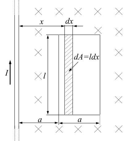
Figure 2S.8 Calculation of the magnetic flux through frame of area Aal .
In this case, the magnetic field vector B is perpendicular to the plane of the frame. Therefore, for all points of the frame we have n ВВ The magnetic field B generated by an infinitely long straight current-carrying conductor is given by the equation:
, 2 I B x
where x is the distance from the wire to the point at which B is determined. In order to calculate the magnetic flux, we note that since B depends on x , the elementary flux dФ will also depend on x :
We divide the area of the frame to narrow elementary areas of height l , width dx, and area dAldx . Within this area the magnetic field can be considered constant, since all the points within dA are at a distance x from the wire. The elementary magnetic flux can be written as:
. 2 I dldx x
By integrating this expression between 1 xa and 2 2 ха we find:
By substituting the limits, we get:
Performing numerical calculations, we obtain 4.50 µWb Ф .
Problem 2.11 An electron of velocity 62.0010 m/s v , enters a uniform magnetic field of 30.0 mT B at an angle 30 to the direction of the magnetic field lines. Determine the radius R and pitch h of the helical path followed by the electron (Fig. 2S.9).

Figure 2S.9 Helical path of an electron in a magnetic field.
Solution The Lorentz force which is perpendicular to the magnetic B and the velocity v of the particle is determined by the equation:
where q is the charge of the particle. If the particle is an electron, the equation for the force may be written as
FevB ,
where e is the electron charge. Since the Lorentz force vector is perpendicular to the velocity vector, the magnitude of the velocity will not change under the influence of this force, but its direction will change. From mechanics we know that a constant force perpendicular to the velocity results in circular motion. Therefore, an electron which enters a uniform magnetic field will move on a circular orbit in a plane perpendicular to the magnetic field, with a speed equal to the transverse velocity component v (see Fig. 2S.9); at the same time it will move along the field with a constant velocity v :
The result of the simultaneous circular motion and this motion along a straight line is that the electron will move along a helical path shown in Fig. 2S.9.
The radius of the circle can be calculated from the condition that the Lorentz force LF is equal to the centripetal force:
the radius of the helix:
By substituting the values of ,,,, тveВ and and performing calculations, we obtain 0.19 mm R . The pitch of the helix is equal to the distance that electron covered along the field with speed v for the time it takes an electron to complete one circle on the orbit, ,h=vT
where 2 T=R/v is the period of the electron rotation. With this in mind, we find the expression for the pitch h :