UNIT 1 Contract Documents and Drawings
REVIEW
Students were asked to write all answers in complete sentences, show calculations in detail, and cite Code references when appropriate.
1. List the drawings that are normally included in an electrical drawing set.
Legend of symbols, site plan, lighting and power electrical floor plans, power riser diagram, elevations, details, sections, schedules, shop drawings. See The Drawing Set.
2. List the steps to be followed when working with a set of drawings.
• Check that the drawing set is complete.
• Review the floor plans and elevations to get a mental picture of the size and shape of the building.
• Orient the building to the site using the plot plan. Be sure that you know which sides are north, south, east, and west. Add this information to your floor plans.
• Verify the scale of all drawings.
• Identify the types of construction materials (combustible or non-combustible) and components shown in the drawings. Nonstandard items should be shown in a legend of symbols.
• Read all notes on the drawings carefully.
• Relate details to larger views.
• Note multiple or identical drawings. Typical means uniform throughout the building.
• Coordinate the electrical layout and installation with other trades.
See Units | Working with the Drawings
3. Measure the length of each line using the metric scale indicated. (Use these numbers as approximations. Variations occur during the printing process and the lines will vary in length between one printing run and the next.)
a. 1:20 1.8 m
b. 1:50 4.0 m
c. 1:100 8.9 m
d. 1:75 4.7 m
e. 1:25 2.2 m
f. 1:125 11.0 m
g. 1:100 7.7 m
h. 1:20 1.8 m
i. 1:50 4.4 m
j. 1:100 7.5 m
See Units.
4. Measure the length of each line using the architectural scale indicated. (Use these numbers as approximations. Variations occur during the printing process and the lines will vary in length between one printing run and the next.)
a. 1/8 in. = 1 ft 21′ 14″
b. 1/4 in. = 1 ft 13′ 4″
c. 1/2 in. = 1 ft 8′ 0″
d. 1-1/2 in. = 1 ft 2′ 1″
e. 3/8 in. = 1 ft 10′ 0″
f. 3/4 in. = 1 ft 5′ 4″
g. 1/4 in. = 1 ft 13′ 3″
h. 1/8 in. = 1 ft 30′ 4″
i. 1/4 in. = 1 ft 13′ 9″
j. 3/8 in. = 1 ft 10′ 9″
See Units.
5. Identify the construction event during which the following electrical activities should take place.
a. Trenching and underground work = Site preparation
b. Feeders = Building enclosure
c. Finishing = Floor finishing
d. Panelboards = Interior walls, partitions, and ceilings
e. Branch circuits and pulling wire = Interior walls, partitions, and ceilings
f. Embedded work = Footings and foundations, superstructure and floors
See Table 1-3.
6. Draw the symbol for each of the following items found on a site plan.
a. Existing contour lines
b. Finished contour lines
c. Benchmark
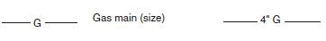
d. Gas line
e. Fence line
f. Property line
See Figure 1-2


7. Give the measurement indicated by each dimension in the diagram below.

They are 1/2″ , 1-1/4″ , 2-3/16″, 3-1/8″ , 4-11/32″, 5-13/16″ See Figure 1-3.
8. Determine the following using the blueprint drawings supplied with this textbook. (Use these numbers as approximations. Variations occur during the printing process and the lines will vary in length between one printing run and the next )
a. What is the distance (in metres) from the south lot line to the southeast corner of the building?
The distance from the south lot line to the southeast corner of the building is 85 × 500 = 42 500 mm = 42.5 m. See Drawing A1 or E2.
b. Where is the new electrical room to be located?
The new electrical room is located at column lines A15 to B14 See Drawing E4.
c. What are the kVA and voltage ratings of the new transformers supplying power to this building?
The kVA and voltage ratings of the two new transformers used to supply this building are 1000 kVA and 27 600V-347/600V. See Drawing E2 or E6.
d. Where is the chiller to be located?
There are two chillers located in the chiller room. See Drawing E4 or M1.
e. Where is lighting panel “D” to be located?
Lighting panel D is between column lines A12 and A13. See Drawing E4.
f. What is the voltage and ampere rating of power panel 102?
The voltage and current rating of PP102 is 120/208V 225A main busses and 200A main breaker. See Electrical Specifications: PP-102 Panel Schedule.
9. Perform the following conversions using the conversion factors in Figure 1-4.
a. 12.5 mm to inches = 12.5 / 25.4 = 0.492″
b. 25.4 mm to inches = 25.4 / 25.4 = 1″
c. 500 mm to inches = 500 / 25.4 = 19.69″
d. 6000 mm to inches = 6000 / 25.4 = 236.22″
e. 3412 mm to feet = 3412 / 304.8 = 11.19′
f. 0.025 mm to feet = 0.025 / 304.8 = 8.2 × 10⁻⁵′
g. 1/8 in. to millimetres = 1/8 × 25.4 = 3.175 mm
h. 1/4 in. to millimetres = ¼ × 25.4 = 6.35 mm
i. 1/2 in. to millimetres = ½ × 25.4 = 12.7 mm
j. 9/64 in. to millimetres = 9/64 × 25.4 = 3.57 mm
10. Which drawings reflect the physical location of materials and equipment where they were installed?
a. Shop drawings
b. As-built drawings
c. Architectural drawings
d. Sectional drawings
See The Drawing Set | As-Built Drawings.