CHAPTER 1
Exercises
E1.1 Charge = Current Time = (2 A) (10 s) = 20 C
E1.2 )()(0t)0.01200cos(200)2cos(200)A tt
E1.3 Because i2 has a positive value, positive charge moves in the same direction as the reference. Thus, positive charge moves downward in element C .
Because i3 has a negative value, positive charge moves in the opposite direction to the reference. Thus positive charge moves upward in element E .
E1.4 Energy = Charge Voltage = (2 C) (20 V) = 40 J
Because vab is positive, the positive terminal is aand the negative terminal is b . Thus the charge moves from the negative terminal to the positive terminal, and energy is removed from the circuit element.
E1.5 iab enters terminal a. Furthermore, vab is positive at terminal a. Thus the current enters the positive reference, and we have the passive reference configuration.
orsaleofanypartofthiswork(includingontheWorldWideWeb) willdestroytheintegrityoftheworkandisnotpermitted.
(b) Notice that the references are opposite to the passive sign convention. Thus we have:
E1.7 (a) Sum of currents leaving = Sum of currents entering ia = 1 + 3 = 4 A
(b) 2 = 1 + 3 + ib ib = -2 A
(c) 0 = 1 + ic + 4 + 3 ic = -8 A
E1.8 Elements Aand Bare in series. Also, elements E , F , and Gare in series.
E1.9 Go clockwise around the loop consisting of elements A, B , and C: -3 - 5 +vc = 0 vc = 8 V
Then go clockwise around the loop composed of elements C , Dand E: - vc - (-10) + ve = 0 ve = -2 V
E1.10 Elements Eand Fare in parallel; elements Aand Bare in series.
E1.11 The resistance of a wire is given by A RL ρ . Using 4/ 2 dA and substituting values, we have:
ThisworkisprotectedbyUnitedStatescopyrightlaws andisprovidedsolelyfortheuseofinstructorsinteaching theircoursesandassessingstudentlearning. Dissemination orsaleofanypartofthiswork(includingontheWorldWideWeb) willdestroytheintegrityoftheworkandisnotpermitted.
E1.14 Using KCL at the top node of the circuit, we have i1 = i2. Then, using KVL going clockwise, we have -v1 - v2 = 0; but v1 = 25 V, so we have v2 = -25 V. Next we have i1 = i2 = v2/R= -1 A. Finally, we have )1()25W (25
ivP R and )1()25W. (25
E1.15 At the top node we have iR = is = 2A. By Ohm’s law we have vR =RiR = 80 V. By KVL we have vs =vR = 80 V. Then ps =-vsis = -160 W (the minus sign is due to the fact that the references for vs and is are opposite to the passive sign configuration). Also we have 160W. RRRivP
Problems
P1.1 Broadly, the two objectives of electrical systems are:
1. To gather, store, process, transport and present information.
2. To distribute, store, and convert energy between various forms.
P1.2 Four reasons that non-electrical engineering majors need to learn the fundamentals of EE are:
1. To pass the Fundamentals of Engineering Exam.
2. To be able to lead in the design of systems that contain electrical/electronic elements.
3. To be able to operate and maintain systems that contain electrical/electronic functional blocks.
P1.3 Eight subdivisions of EE are:
1. Communication systems.
2. Computer systems.
3. Control systems.
4. Electromagnetics.
5. Electronics.
6. Photonics.
7. Power systems.
8. Signal Processing.
ThisworkisprotectedbyUnitedStatescopyrightlaws andisprovidedsolelyfortheuseofinstructorsinteaching theircoursesandassessingstudentlearning.
P1.4 Responses to this question are varied.
Dissemination orsaleofanypartofthiswork(includingontheWorldWideWeb) willdestroytheintegrityoftheworkandisnotpermitted.
4. To be able to communicate effectively with electrical engineers.
P1.5 (a) Electrical current is the time rate of flow of net charge through a conductor or circuit element. Its units are amperes, which are equivalent to coulombs per second.
(b) The voltage between two points in a circuit is the amount of energy transferred per unit of charge moving between the points. Voltage has units of volts, which are equivalent to joules per coulomb.
(c) The current through an open switch is zero. The voltage across the switch can be any value depending on the circuit.
(d) The voltage across a closed switch is zero. The current through the switch can be any value depending of the circuit.
(e) Direct current is constant in magnitude and direction with respect to time.
(f) Alternating current varies either in magnitude or direction with time.
P1.6 (a) A conductor is anagolous to a frictionless pipe.
(b) An open switch is anagolous to a closed valve.
(c) A resistance is anagolous to a constriction in a pipe or to a pipe with friction.
(d) A battery is analogous to a pump.
Electronspersecond1coulomb/s
P1.7 18 19 2510 6010coulomb/electron
P1.8* The reference direction for abi points from ato b. Because abi has a negative value, the current is equivalent to positive charge moving opposite to the reference direction. Finally since electrons have negative charge, they are moving in the reference direction (i.e., from ato b).
For a constant (dc) current, charge equals current times the time interval. Thus, A)(3s)15C.
Q
ThisworkisprotectedbyUnitedStatescopyrightlaws andisprovidedsolelyfortheuseofinstructorsinteaching theircoursesandassessingstudentlearning. Dissemination orsaleofanypartofthiswork(includingontheWorldWideWeb) willdestroytheintegrityoftheworkandisnotpermitted.
P1.9 The positive reference for vis at the head of the arrow, which is terminal a. The positive reference for vbais terminal b . Thus, we have 12V. vv ba Also, i is the current entering terminal a, and iba is the current leaving terminal a. Thus, we have 2A. ba ii Thus, current enters the positive reference and energy is being delivered to the device.
P1.10
To stop current flow, we break contact between the conducting parts of the switch, and we say that the switch is open. The corresponding fluid
analogy is a valve that does not allow fluid to pass through. This corresponds to a closed valve. Thus, a closed valve is analogous to an open switch.
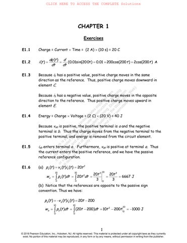
P1.12 (a) The sine function completes one cycle for each 2 radian increase in the angle. Because the angle is , 200 t one cycle is completed for each time interval of 0.01 s. The sketch is:
P1.15 The number of electrons passing through a cross section of the wire per second is
The volume of copper containing this number of electrons is
The cross sectional area of the wire is
Finally, the average velocity of the electrons is volume2840mm/s
P1.16* The charge flowing through the battery is ()amperes360024)seconds43210coulombs 3
and the stored energy is
(a) Equating gravitational potential energy, which is mass times height times the acceleration due to gravity, to the energy stored in the battery and solving for the height, we have
(b) Equating kinetic energy to stored energy and solving for velocity, we have
(c) The energy density of the battery is
which is about 0.384% of the energy density of gasoline.
Because iba is positive, if the current were carried by positive charge it would be entering terminal b . Electrons enter terminal a. The energy is taken from the element.
5
P1.20 If the current is referenced to flow into the positive reference for the voltage, we say that we have the passive reference configuration. Using double subscript notation, if the order of the subscripts are the same for the current and voltage, we have a passive reference configuration.
P1.21* (a) P -vaia = 30 W Energy is being absorbed by the element.
(b) P vbib = 30 W Energy is being absorbed by the element.
(c) P -vDEiED = -60 W Energy is being supplied by the element.
P1.22 The amount of energy is (3C)(10V)30J. WQV Because the reference polarity is positive at terminal aand the voltage value is negative, terminal bis actually the positive terminal. Because the charge moves from the negative terminal to the positive terminal, energy is removed from the device.
P1.23* (12V)50C(600J) VwQ .
To increase the chemical energy stored in the battery, positive charge should move from the positive terminal to the negative terminal, in other words from ato b . Electrons move from bto a.
The element absorbs the energy.
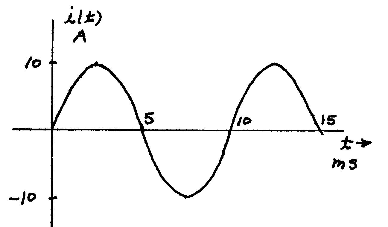
P1.25 (a))(50sin(200)Wivtpt
Reduction60
P1.27 (a) P 60 W delivered to element A. (b) takenfromelementA. 60W P (c) P 60 W delivered to element A .
P1.28* (a) Wtakenfromelement.P60A (b) element. WdeliveredtoP60A
(c) Wtakenfromelement.P60A
P1.29 The power that can be delivered by the cell is 12W. pvi In 75 hours, the energy delivered is 9Whr0.009kWhr.WpT Thus the unit cost of the energy is .0(50)/(009)55.56$/kWhr Cost which is 463 times the typical cost of energy from electric utilities. ThisworkisprotectedbyUnitedStatescopyrightlaws andisprovidedsolelyfortheuseofinstructorsinteaching theircoursesandassessingstudentlearning. Dissemination orsaleofanypartofthiswork(includingontheWorldWideWeb) willdestroytheintegrityoftheworkandisnotpermitted.
P1.30 The current supplied to the electronics is .36.968A./50/12 vpi
iT
The energy delivered by the battery is 1260)2.wh1.26kWh. 50(25 WpT
The ampere-hour rating of the battery is the operating time to discharge the battery multiplied by the current. Thus, the operating time is /10025hours.
Neglecting the cost of recharging, the cost of energy for 300 discharge cycles is 1984.0)$/kWh.75/(30026 Cost
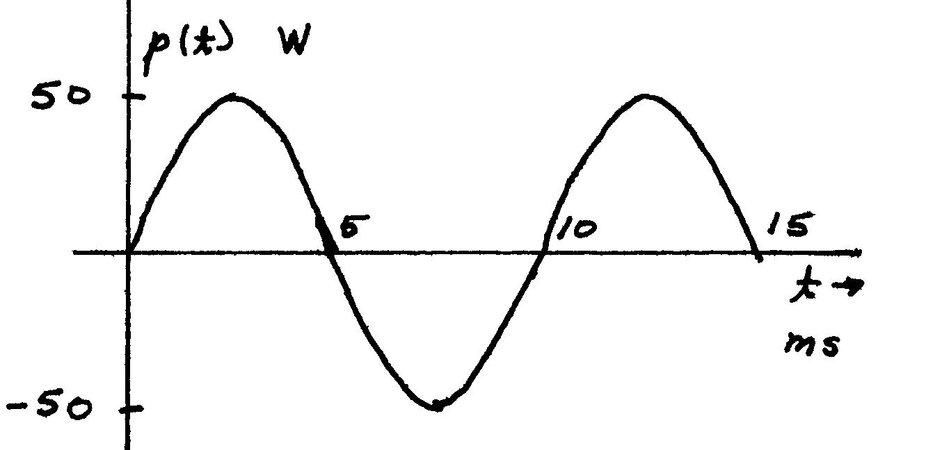
P1.31 A node is a point that joins two or more circuit elements. All points joined by ideal conductors are electrically equivalent. Thus, there are four nodes in the circuit at hand:
P1.32 The sum of the currents entering a node equals the sum of the currents leaving.
P1.33 The currents in series-connected elements are equal.
ThisworkisprotectedbyUnitedStatescopyrightlaws andisprovidedsolelyfortheuseofinstructorsinteaching theircoursesandassessingstudentlearning. Dissemination orsaleofanypartofthiswork(includingontheWorldWideWeb) willdestroytheintegrityoftheworkandisnotpermitted.
P1.34 For a proper fluid analogy to electric circuits, the fluid must be incompressible. Otherwise the fluid flow rate out of an element could be more or less than the inward flow. Similarly the pipes must be inelastic so the flow rate is the same at all points along each pipe.
P1.35* Elements Aand Bare in series. Also, elements Eand Fare in series.
P1.36 (a) Elements Cand Dare in series.
(b) Because elements Cand Dare in series, the currents are equal in magnitude. However, because the reference directions are opposite, the algebraic signs of the current values are opposite. Thus, we have d cii .
c dii
(c) At the node joining elements A, B , and C , we can write the KCL equation 314A bcaiii . Also we found earlier that 1A.
P1.37* At the node joining elements A and B, we have b aii Thus, 2A. ai For the node at the top end of element C, we have 3 c bii . Thus, 1A ci . Finally, at the top right-hand corner node, we have .3 d eii Thus, 4A di . Elements Aand B are in series.
P1.38* ApplyingKCL,wefindand4A.aregiven2A,3A,5A, We
iii
P1.39 and1A.aregiven1A,3A,5A, We h g c a iiii Applying KCL, we find
ThisworkisprotectedbyUnitedStatescopyrightlaws andisprovidedsolelyfortheuseofinstructorsinteaching theircoursesandassessingstudentlearning. Dissemination
P1.40 If one travels around a closed path adding the voltages for which one enters the positive reference and subtracting the voltages for which one enters the negative reference, the total is zero.
P1.41 (a) Elements Aand Bare in parallel.
(b) Because elements Aand Bare in parallel, the voltages are equal in magnitude. However because the reference polarities are opposite, the algebraic signs of the voltage values are opposite. Thus, we have .b a vv
(c) Writing a KVL equation while going clockwise around the loop composed of elements A,Cand D , we obtain
a b vv
c d a vvv Solving for cv and substituting values, we find 7V. cv Also we have 2V.
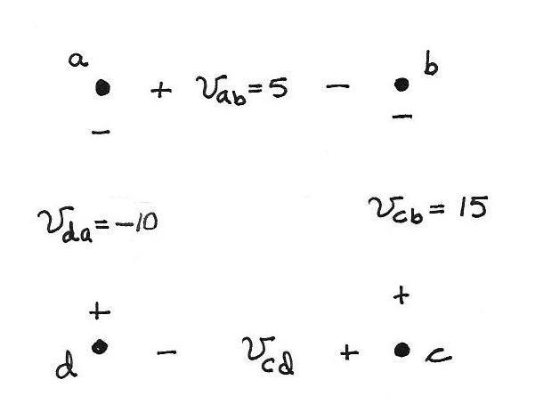
P1.42* Summing voltages for the lower left-hand loop, we have 510 av which yields 5V. av Then for the top-most loop, we have 15,0 a c vv which yields 10V. cv Finally, writing KCL around the outside loop, we have 5 b c vv which yields 5V. bv
P1.43 We are given and6V.5V,7V,10V, h f b a vvvv Applying KVL, we find
P1.44* Applying KCL and KVL, we have 1A
a db vvvV 4 d c vv The power for each element is 20W
P1.45 (a) In Figure P1.28, elements C , D , and Eare in parallel. (b) In Figure P1.33, no element is in parallel with another element. (c) In Figure P1.34, elements Cand Dare in parallel.
ThisworkisprotectedbyUnitedStatescopyrightlaws andisprovidedsolelyfortheuseofinstructorsinteaching theircoursesandassessingstudentlearning.
orsaleofanypartofthiswork(includingontheWorldWideWeb) willdestroytheintegrityoftheworkandisnotpermitted.
P1.46 The points and the voltages specified in the problem statement are:
Applying KVL to the loop abca , substituting values and solving, we obtain:
Similiarly, applying KVL to the loop abcda , substituting values and solving, we obtain:
P1.47 (a) The voltage between any two points of an ideal conductor is zero regardless of the current flowing.
(b) An ideal voltage source maintains a specified voltage across its terminals.
(c) An ideal current source maintains a specified current through itself.
P1.48 Four types of controlled sources and the units for their gain constants are:
1. Voltage-controlled voltage sources. V/V or unitless.
2. Voltage-controlled current sources. A/V or siemens.
3. Current-controlled voltage sources. V/A or ohms.
4. Current-controlled current sources. A/A or unitless.
P1.49 Provided that the current reference points into the positive voltage reference, the voltage across a resistance equals the current through the resistance times the resistance. On the other hand, if the current reference points into the negative voltage reference, the voltage equals the negative of the product of the current and the resistance.
P1.50*
ThisworkisprotectedbyUnitedStatescopyrightlaws andisprovidedsolelyfortheuseofinstructorsinteaching theircoursesandassessingstudentlearning. Dissemination orsaleofanypartofthiswork(includingontheWorldWideWeb) willdestroytheintegrityoftheworkandisnotpermitted.
P1.52 The resistance of the copper wire is given by ALR Cu Cu , and the resistance of the tungsten wire is ALR W W . Taking the ratios of the respective sides of these equations yields Cu W Cu W RR . Solving for WR and substituting values, we have

ThisworkisprotectedbyUnitedStatescopyrightlaws andisprovidedsolelyfortheuseofinstructorsinteaching theircoursesandassessingstudentlearning. Dissemination orsaleofanypartofthiswork(includingontheWorldWideWeb) willdestroytheintegrityoftheworkandisnotpermitted.
P1.56 The power delivered to the resistor is )4exp(5.2/)()( 2 Rtvtpt and the energy delivered is 625J 4 )4exp(5.2 4 )4exp(5.2)(5.2
P1.57 The power delivered to the resistor is )4cos( .1)2(sin5.2/)()(2525 2 2 Rtvtptt
and the energy delivered is
P1.58 Equation 1.10 gives the resistance as
P1.59
(a) Thus, if the length of the wire is doubled, the resistance doubles to . 1
(b) If the diameter of the wire is doubled, the cross sectional area Ais increased by a factor of four. Thus, the resistance is decreased by a factor of four to 0.125
ThisworkisprotectedbyUnitedStatescopyrightlaws andisprovidedsolelyfortheuseofinstructorsinteaching theircoursesandassessingstudentlearning.
Dissemination orsaleofanypartofthiswork(includingontheWorldWideWeb) willdestroytheintegrityoftheworkandisnotpermitted.
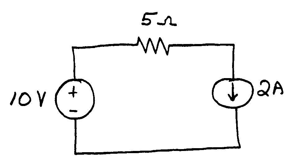
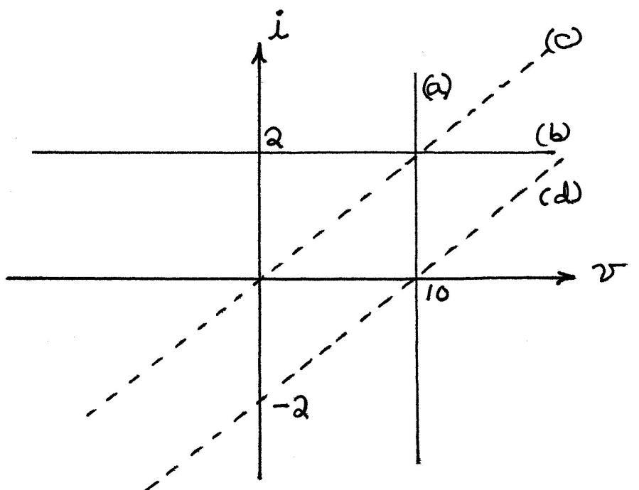
(a) The voltage across the voltage source is 10 V independent of the current. Thus, we have v 10 which plots as a vertical line in the v i plane.
(b) The current source has i 2 independent of v, which plots as a horizontal line in the v iplane.
(c) Ohm's law gives i v/5.
(d) Applying Ohm's law and KVL, we obtain 10 5 iv which is equivalent to22.0vi .
(e) Applying KCL and Ohm's law, we obtain obtain 10 5 iv which is equivalent to22.0vi .
The plots for all five parts are shown. (Parts d and e have the same plot.)
P1.60* (a) Not contradictory.
(b) A 2-A current source in series with a 3-A current source is contradictory because the currents in series elements must be equal.
(c) Not contradictory.
(d) A 2-A current source in series with an open circuit is contradictory because the current through a short circuit is zero by definition and currents in series elements must be equal.
(e) A 5-V voltage source in parallel with a short circuit is contradictory because the voltages across parallel elements must be equal and the voltage across a short circuit is zero by definiton.
P1.61 The power for each element is 20 W. The current source delivers power and the voltage source absorbs it.
P1.62*
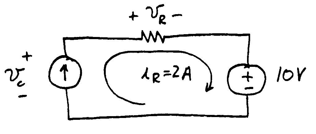
As shown above, the 2 A current circulates clockwise through all three elements in the circuit. Applying KVL, we have
Piv Thus, the current source delivers power.
52)(20W. 2 2 RiPRR The resistor absorbs power.
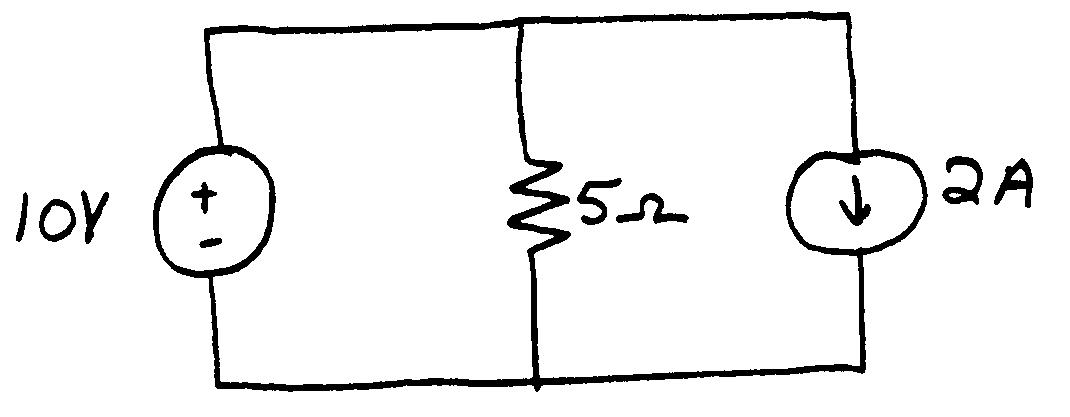
P1.63 This is a parallel circuit and the voltage across each element is 10 V positive at the top end. Thus, the current through the resistor is
Applying KCL, we find that the current through the voltage source is zero. Computing power for each element, we find
Thus, the current source delivers power.
P1.64*
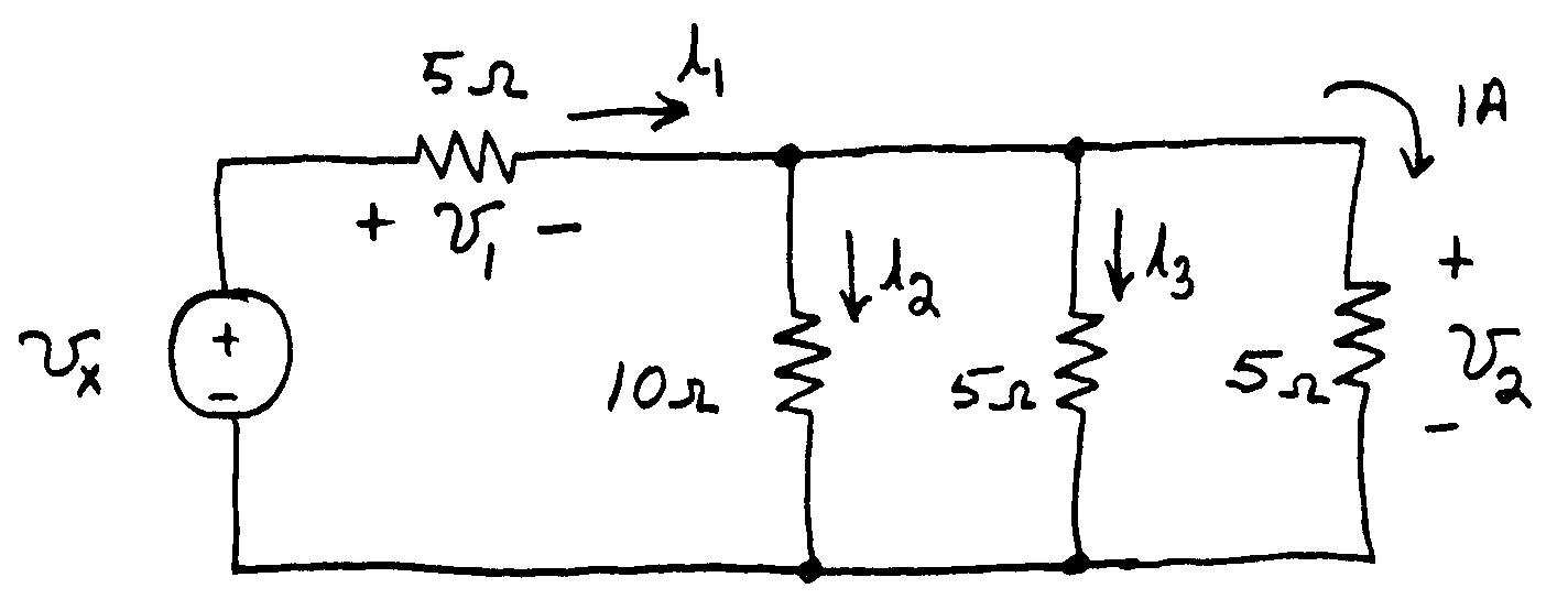
Applying Ohm's law, we have 515AV 2 v . However, 2v allthreeresistorsthatareinparallel.Thus, is 1A 5 2 3 iv , and 5.0A 10 2 2 iv . Applying KCL, we have 5.21A 321 iii . By Ohm's law: 512V 11iv . Finally using KVL, we have 17V 21vvv x .
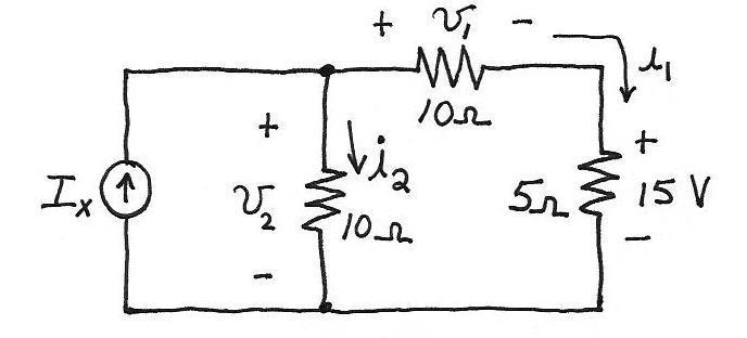
P1.65
ThisworkisprotectedbyUnitedStatescopyrightlaws andisprovidedsolelyfortheuseofinstructorsinteaching theircoursesandassessingstudentlearning.
orsaleofanypartofthiswork(includingontheWorldWideWeb) willdestroytheintegrityoftheworkandisnotpermitted.
Ohm’s law for the 5- resistor yields: 35/A. 15 1 i Then for the 10- resistor, we have 1030V. 11 iv Using KVL, we have 1545V. 12 vv Then applying Ohms law, we obtain /105.4A. 22 vi Finally applying KCL, we have 5.7A. 21iiI x
P1.66 (a) The 3- resistance, the 2- resistance, and the voltage source Vx are in series.
(b) The 6- resistance and the 12- resistance are in parallel.
(c) Refer to the sketch of the circuit. Applying Ohm's law to the 12- resistance, we determine that 6 1 v V. Then, applying Ohm's law to the 6- resistance, we have 1 1 i A. Next, KVL yields 5.1 2 i A. Continuing,
we use Ohm's law to find that 3 2 v V and 5.4 3 v V. Finally, applying KVL, we have 13 213vvvV x

P1.67 First, we have A. 18/ oo Pi
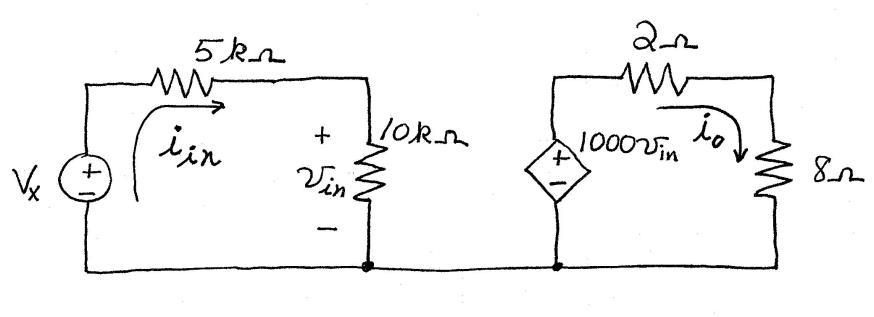
Applying Ohm's law and KVL to the right-hand loop we have inoo 821000iiv from which we determine that 10mV. inv Then, /101A 4 inin vi , and finally we have 50001000015mV. in in x
P1.68 (a) No elements are in series. ThisworkisprotectedbyUnitedStatescopyrightlaws andisprovidedsolelyfortheuseofinstructorsinteaching theircoursesandassessingstudentlearning. Dissemination orsaleofanypartofthiswork(includingontheWorldWideWeb) willdestroytheintegrityoftheworkandisnotpermitted.
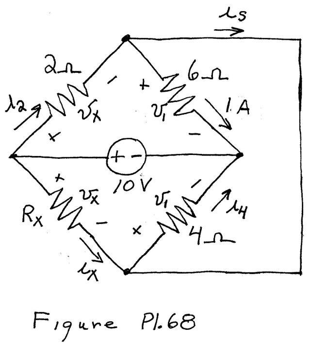
(b) Rx and the 2- resistor are in parallel. Also, the 6- resistor and the the 4- resistor are in parallel. Thus, the voltages across the parallel elements are the same as labeled in the figure.
(c) 6V 1 v 5.14/A 1 4
P1.70* (a) Applying KVL, we have xx vv5 10 , which yields .16/667V 10 xv (b) .03/5556A xx vi
P1.71
(c) W. 556 10 x source voltage i P (This represents power delivered by the voltage source.) .0)(3926W(absorbed) 2
x R iP .4563W(absorbed)
xx source controlled Piv
Applying KVL around the periphery of the circuit, we have ThisworkisprotectedbyUnitedStatescopyrightlaws andisprovidedsolelyfortheuseofinstructorsinteaching
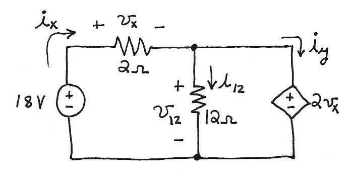
18,02 xxvv which yields 6 xv V. Then we have 212 12 x vv V.
Using Ohm’s law we obtain /121 1212 vi A and 32/ xx vi A. Then KCL applied to the node at the top of the 12- resistor gives y xiii 12 which yields 2 yi A.
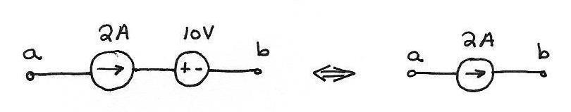
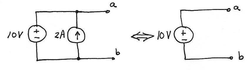
P1.72 Consider the series combination shown below on the left. Because the current for series elements must be the same and the current for the current source is 2 A by definition, the current flowing from ato bis 2 A. Notice that the current is not affected by the 10-V source in series. Thus, the series combination is equivalent to a simple current source as far as anything connected to terminals aand bis concerned.
P1.73 Consider the parallel combination shown below. Because the voltage for parallel elements must be the same, the voltage vab must be 10 V. Notice that vab is not affected by the current source. Thus, the parallel combination is equivalent to a simple voltage source as far as anything connected to terminals aand bis concerned.
P1.75*
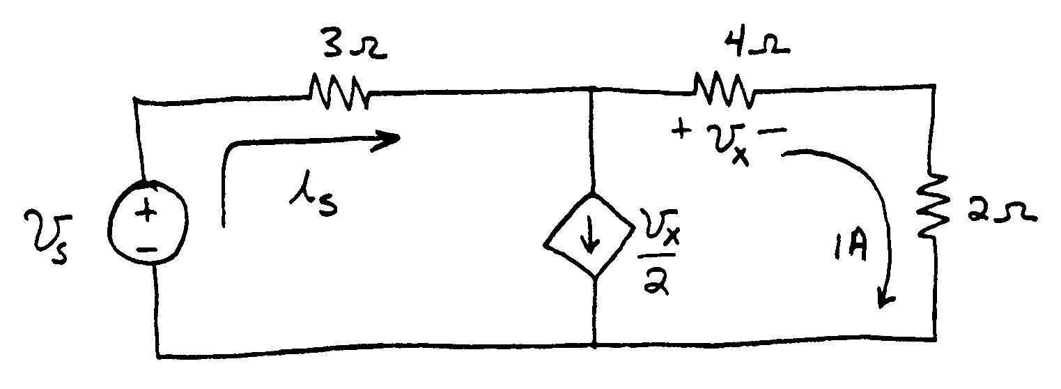
1()4)AV x vA 312/ xs vi
Applying KVL around the outside of the circuit, we have: 24315V ssiv
P1.76V/152A 30 xi
Applying KCL for the node at the top end of the controlled current source: 12/A
The source labled is is an independent current source. The source labeled ix/2 is a current-controlled current source.
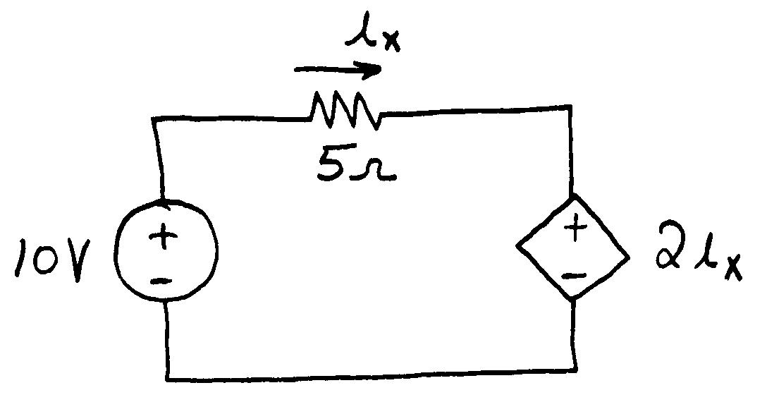
P1.77 Applying Ohm's law and KVL, we have 2010.5 xx ii Solving, we obtain 4A. xi
ThisworkisprotectedbyUnitedStatescopyrightlaws andisprovidedsolelyfortheuseofinstructorsinteaching theircoursesandassessingstudentlearning.
Dissemination orsaleofanypartofthiswork(includingontheWorldWideWeb) willdestroytheintegrityoftheworkandisnotpermitted.
The source labeled 20 V is an independent voltage source. The source labeled 5ix is a current-controlled voltage source.
Practice Test
T1.1 (a) 4; (b) 7; (c) 16; (d) 18; (e) 1; (f) 2; (g) 8; (h) 3; (i) 5; (j) 15; (k) 6; (l) 11; (m) 13; (n) 9; (o) 14.
T1.2 (a) The current Is 3 A circulates clockwise through the elements entering the resistance at the negative reference for vR. Thus, we have vR IsR 6 V.
(b) Because Is enters the negative reference for Vs, we have PV VsIs 30 W. Because the result is negative, the voltage source is delivering energy.
(c) The circuit has three nodes, one on each of the top corners and one along the bottom of the circuit.
(d) First, we must find the voltage vI across the current source. We choose the reference shown:
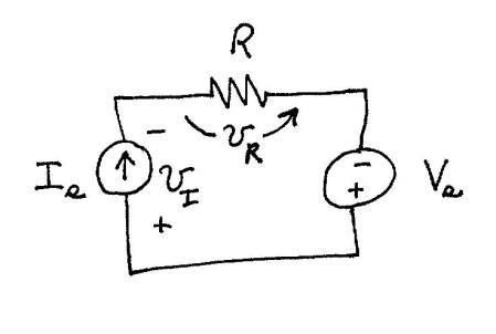
Then, going around the circuit counterclockwise, we have
, which yields
I vVv V. Next, the power for the current source is 12 I s I vIP W. Because the result is positive, the current source is absorbing energy.
Alternatively, we could compute the power delivered to the resistor as 18 2
RIP s R W. Then, because we must have a total power of zero for the entire circuit, we have 301218
T1.3 (a) The currents flowing downward through the resistances are vab/R1 and vab/R2. Then, the KCL equation for node a (or node b) is
Substituting the values given in the question and solving yields vab 8 V. (b) The power for current source I1 is 3824W 1 1
IvP ab I .
Because the result is negative we know that energy is supplied by this current source. The power for current source I2 is 818W 2 2
IvP ab I . Because the result is positive, we know that energy is absorbed by this current source.
(c) The power absorbed by R1 is/)8(/1233W. 2 1 2 1
RvP ab R The power absorbed by R2 is 6/)8(/1067W. 2 2 2 2
T1.4 (a) Applying KVL, we have 21 vvV s Substituting values given in the problem and solving we find 8V. 1 v
(b) Then applying Ohm's law, we have 24/8/A. 11 Rvi (c) Again applying Ohm's law, we have 22/4/. 22 ivR
T1.5 Applying KVL, we have xsvV Thus, 15V. sxVv Next Ohm's law gives /15/105.1A. Rvi xx Finally, KCL yields 3.05.1153A.
x x sc iiav
T1.6 Applying Ohm’s law to the 40-Ω resistance, we have 4080 4 4 iv V Since v4 is also the voltage across the 20-Ω and 16-Ω resistances, we have /1680/165A 4 3 vi and 8020/204A. / 4 2 vi Then applying KCL to the node joining the resistances, we have 11A. 4 321 iiii Then, applying Ohm’s law to the 10-Ω resistance, we have 10110 11 iv V. Finally, applying KVL, we have 190 4 1 vvv s V.
ThisworkisprotectedbyUnitedStatescopyrightlaws andisprovidedsolelyfortheuseofinstructorsinteaching theircoursesandassessingstudentlearning. Dissemination orsaleofanypartofthiswork(includingontheWorldWideWeb) willdestroytheintegrityoftheworkandisnotpermitted.