Solution 2.1
Design a problem, complete with a solution, to help students to better understand Ohm’s Law. Use at least two resistors and one voltage source. Hint, you could use both resistors at once or one at a time, it is up to you. Be creative.
Although there is no correct way to work this problem, this is an example based on the same kind of problem asked in the third edition.
Problem
The voltage across a 5-k Ω resistor is 16 V. Find the current through the resistor.
Solution
v = iR i = v/R = (16/5) mA = 3.2 mA
Copyright © 2017 McGraw-Hill Education. All rights reserved. No reproduction or distribution without the prior written consent of McGraw-Hill Education.
Solution 2.2
p = v2/R → R = v2/p = 14400/60 = 240 ohms
Copyright © 2017 McGraw-Hill Education. All rights reserved. No reproduction or distribution without the prior written consent of McGraw-Hill Education.
Solution 2.3
Copyright © 2017 McGraw-Hill Education. All rights reserved. No reproduction or distribution without the prior written consent of McGraw-Hill Education.
Solution 2.4
(a) i = 40/100 = 400 mA
(b) i = 40/250 = 160 mA
Copyright © 2017 McGraw-Hill Education. All rights reserved. No reproduction or distribution without the prior written consent of McGraw-Hill Education.
Solution 2.5 n = 9; l = 7; b = n + l – 1 = 15
Copyright © 2017 McGraw-Hill Education. All rights reserved. No reproduction or distribution without the prior written consent of McGraw-Hill Education.
Solution 2.6 n = 8; l = 8; b = n + l –1 = 15
Copyright © 2017 McGraw-Hill Education. All rights reserved. No reproduction or distribution without the prior written consent of McGraw-Hill Education.
Solution 2.7
6 branches and 4 nodes
Copyright © 2017 McGraw-Hill Education. All rights reserved. No reproduction or distribution without the prior written consent of McGraw-Hill Education.
Solution 2.8
Design a problem, complete with a solution, to help other students to better understand Kirchhoff’s Current Law. Design the problem by specifying values of i a , i b , and i c , shown in Fig. 2.72, and asking them to solve for values of i 1 , i 2 , and i 3 . Be careful specify realistic currents.
Although there is no correct way to work this problem, this is one of the many possible solutions. Note that the solution process must follow the same basic steps.
Problem
Use KCL to obtain currents i 1, i 2, and i 3 in the circuit shown in Fig. 2.72 given that i a = 2 amps, i b = 3 amps, and i c = 4 amps.
Solution
node c,
We can use node d as a check, i a i 3 i c = 2 + 2 4 = 0 which is as expected.
Copyright © 2017 McGraw-Hill Education. All rights reserved. No reproduction or distribution without the prior written consent of McGraw-Hill Education.
Solution 2.9
Find 123 , i, and i i in Fig. 2.73.
Figure 2.73 For Prob. 2.9.
Solution
Step 1. We can apply Kirchhoff’s current law to solve for the unknown currents.
Summing all of the currents flowing out of nodes A, B, and C we get, at A, 1 + (–6) + i 1 = 0; at B, –(–6) + i 2 + 2 = 0; and at C, (–2) + i 3 – 2 = 0.
Step 2. We now can solve for the unknown currents, i 1 = –1 + 6 = 5 amps; i 2 = –6 – 2 = –8 amps; and i 3 = 2 + 2 = 4 amps
Copyright © 2017 McGraw-Hill Education. All rights reserved. No reproduction or distribution without the prior written consent of McGraw-Hill Education.
Solution 2.10
At node 1, –8–i 1 –6 = 0 or i 1 = –8–6 = –14 A At node 2, –(–8)+i 1
Copyright © 2017 McGraw-Hill Education. All rights reserved. No reproduction or distribution without the prior written consent of McGraw-Hill Education.
Copyright © 2017 McGraw-Hill Education. All rights reserved. No reproduction or distribution without the prior written consent of McGraw-Hill Education.
Solution 2.12
For loop 1, –40 –50 +20 + v 1 = 0 or v 1 = 40+50–20 = 70 V
For loop 2, –20 +30 –v 2 = 0 or v 2 = 30–20 = 10 V
For loop 3, –v1 +v2 +v3 = 0 or v3 = 70–10 = 60 V
Copyright © 2017 McGraw-Hill Education. All rights reserved. No reproduction or distribution without the prior written consent of McGraw-Hill Education.
Copyright © 2017 McGraw-Hill Education. All rights reserved. No reproduction or distribution without the prior written consent of McGraw-Hill Education.
Copyright © 2017 McGraw-Hill Education. All rights reserved. No reproduction or distribution without the prior written consent of McGraw-Hill Education.
Solution 2.15
Calculate v and i x in the circuit of Fig. 2.79.
Figure 2.79 For Prob. 2.15.
Solution
Copyright © 2017 McGraw-Hill Education. All rights reserved. No reproduction or distribution without the prior written consent of McGraw-Hill Education.
Solution 2.16
Determine V o in the circuit in Fig. 2.80.
Figure 2.80 For Prob. 2.16.
Solution Apply KVL, –10 + (16+14)I + 25 = 0 or 30I = 10–25 = – or I = –15/30 = –500 mA Also, –10 + 16I + V o = 0 or V o = 10 – 16(–0.5) = 10+8 = 18 V
Copyright © 2017 McGraw-Hill Education. All rights reserved. No reproduction or distribution without the prior written consent of McGraw-Hill Education.
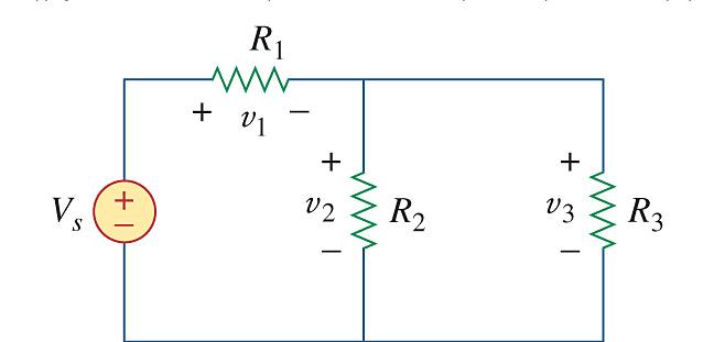
Problem 2.17
Obtain v 1 through v 3 in the circuit in Fig. 2.81
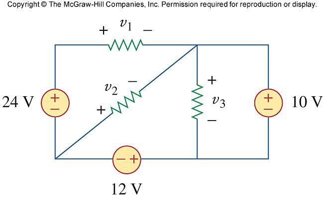
Figure 2.81 For Prob. 2.17.
Copyright © 2017 McGraw-Hill Education. All rights reserved. No reproduction or distribution without the prior written consent of McGraw-Hill Education.
Solution 2.18
Find I and V in the circuit of Fig. 2.82.
–2 amp
Figure 2.82 For Prob. 2.18.
Solution.
Step 1. We can make use of both Kirchhoff’s KVL and KCL. KVL tells us that the voltage across all the elements of this circuit is the same in every case. Ohm’s Law tells us that the current in each resistor is equal to V/R. Finally we can use KCL to find I.
Applying KCL and summing all the current flowing out of the top node and setting it to zero we get, –3 + [V/20] + [V/10] + 4 + [V/20] – [–2] = 0.
Step 2. [0.05+0.1+0.05]V = 0.2V = 3–4–2 = –3 or V = –15 volts. I = 3–V[0.05+0.1] = 3–[–15]0.15 = 5.25 amps. +
Finally at the node to the left of I we can write the following node equation which will give us I, –3 + [V/20] + [V/10] + I = 0.
Copyright © 2017 McGraw-Hill Education. All rights reserved. No reproduction or distribution without the prior written consent of McGraw-Hill Education.
Solution 2.19
Applying KVL around the loop, we obtain
–(–8) – 12 + 10 + 3i = 0 i = –2A
Power dissipated by the resistor:
p Ω 3 = i2R = 4(3) = 12W
Power supplied by the sources:
p 12V = 12 ((–2)) = –24W
p 10V = 10 (–(–2)) = 20W
p 8V = (–8)(–2) = 16W
Copyright © 2017 McGraw-Hill Education. All rights reserved. No reproduction or distribution without the prior written consent of McGraw-Hill Education.
Solution 2.20
Determine i o in the circuit of Fig. 2.84.
Solution Applying KVL around the loop,
+ 22i o + 5i o = 0 i o = 4A
Figure 2.84 For Prob. 2.20
Copyright © 2017 McGraw-Hill Education. All rights reserved. No reproduction or distribution without the prior written consent of McGraw-Hill Education.
Solution 2.21
Applying KVL, -15 + (1+5+2)I + 2 V x = 0
But V x = 5I, -15 +8I + 10I =0, I = 5/6 V x = 5I = 25/6 = 4.167 V
Copyright © 2017 McGraw-Hill Education. All rights reserved. No reproduction or distribution without the prior written consent of McGraw-Hill Education.
Solution 2.22
Find V o in the circuit in Fig. 2.86 and the power absorbed by the dependent source.
Figure 2.86 For Prob. 2.22
Solution
At the node, KCL requires that [–V o /10]+[–25]+[–2V o ] = 0 or 2.1V o = –25 or V o = –11.905 V
The current through the controlled source is i = 2V 0 = –23.81 A and the voltage across it is V 1 = (10+10) i 0 (where i 0 = –V 0 /10) = 20(11.905/10) = 23.81 V.
Hence, p dependent source = V 1 (–i) = 23.81x(–(–23.81)) = 566.9 W
Checking, (25–23.81)2(10+10) + (23.81)(–25) + 566.9 = 28.322 – 595.2 + 566.9 = 0.022 which is equal zero since we are using four places of accuracy!
Copyright © 2017 McGraw-Hill Education. All rights reserved. No reproduction or distribution without the prior written consent of McGraw-Hill Education.
Solution 2.23
In the circuit shown in Fig. 2.87, determine v x and the power absorbed by the 60-Ω resistor.
Figure 2.87 For Prob. 2.23.
Step 1. Although we could directly use Kirchhoff’s current law to solve this, it will be easier if we reduce the circuit first.
The reduced circuit looks like this,
R 1 = 40x60/(40+60)
R 2 = 6 + R 1
R 3 = 15x30/(15+30)
R 4 = 20+R 3
R 5 = R 2 R 4 /(R 2 +R 4 )
Letting V 10 = v x + V R5 and using Kirchhoff’s current law, we get
60 + V 10 /10 + V 10 /(5+R 5 ) = 0
60 + V 10 /10 + V 10 /20 = 0
V 10 = –60x20/3 = –400 volts
Copyright © 2017 McGraw-Hill Education. All rights reserved. No reproduction or distribution without the prior written consent of McGraw-Hill Education.
We could have also used current division to find the current through the 5 Ω resistor, however, i 5 = V 10 /(5+R 5 ) and v x = 5i 5
Calculating the power delivered to the 60-ohm resistor requires that we find the voltage across the resistor. V R5 = V 10 – v x ; using voltage division we get V 60 = [V R5 /(6+R 1 )]R 1 . Finally P 60 = (V 60 )2/60.
Step 2.
R 1 = 40x60/(40+60) = 2400/100 = 24;
R 2 = 6 + R 1 = 6+24 = 30;
R 3 = 15x30/(15+30) 450/45 = 10;
R 4 = 20+R 3 = 20+10 = 30;
R 5 = R 2 R 4 /(R 2 +R 4 ) = 30x30/(30+30) = 15.
Now, we have 60 + (V 10 /10) + (V 10 /(20)) = 0 or V 10 = –60x20/3 = –400 and i 10 = –400/20 = –20 and v x = 5i 5 = 5(–20) = –100 volts
V R5 = V 10 – v x = –400 – (–100) = –300; using voltage division we get V 60 = [V R5 /(6+R 1 )]R 1 . = [–300/30]24 = –240. Finally,
P 60 = (V 60 )2/60 = (–240)2/60 = 960 watts
Copyright © 2017 McGraw-Hill Education. All rights reserved. No reproduction or distribution without the prior written consent of McGraw-Hill Education.
Copyright © 2017 McGraw-Hill Education. All rights reserved. No reproduction or distribution without the prior written consent of McGraw-Hill Education. Solution 2.24
Solution 2.25
V 0 = 5 x 10-3 x 10 x 103 = 50V
Using current division,
I 20 = + = 50) 01 0( 20 5 5 x 0.1 A
V 20 = 20 x 0.1 kV = 2 kV p 20 = I 20 V 20 = 0.2 kW
Copyright © 2017 McGraw-Hill Education. All rights reserved. No reproduction or distribution without the prior written consent of McGraw-Hill Education.
Solution 2.26
For the circuit in Fig. 2.90, i o = 5 A. Calculate i x and the total power absorbed by the entire circuit.
Figure 2.90 For Prob. 2.26.
Solution
Step 1. V 40 = 40i o and we can combine the four resistors in parallel to find the equivalent resistance and we get (1/R eq ) = (1/20) + (1/10) + (1/5) + (1/40).
This leads to i x = V 40 /R eq and P = (i x )2(25+R eq ).
Step 2. V 40 = 40x5 = 200 volts and (1/R eq ) = (1/20) + (1/10) + (1/5) + (1/40) = 0.05 + 0.1 + 0.2 + 0.025 = 0.375 or R eq = 2.667 Ω and i x = 200/R eq = 75 amps. P = (75)2(25+2.667) = 155.62 kW
Copyright © 2017 McGraw-Hill Education. All rights reserved. No reproduction or distribution without the prior written consent of McGraw-Hill Education.
Solution 2.27
Calculate I o in the circuit of Fig. 2.91.
Figure 2.91 For Prob. 2.27.
Solution
The 3-ohm resistor is in parallel with the c-ohm resistor and can be replaced by a [(3x6)/(3+6)] = 2-ohm resistor. Therefore,
Copyright © 2017 McGraw-Hill Education. All rights reserved. No reproduction or distribution without the prior written consent of McGraw-Hill Education.
Solution 2.28
Design a problem, using Fig. 2.92, to help other students better understand series and parallel circuits.
Although there is no correct way to work this problem, this is an example based on the same kind of problem asked in the third edition.
Problem
Find v 1 , v 2 , and v 3 in the circuit in Fig. 2.92
Solution
We first combine the two resistors in parallel = 10 15 6 Ω
We now apply voltage division,
v 1 = = + 40) ( 6 14 14 28 V
v 2 = v 3 = = + 40) ( 6 14 6 12 V
Hence, v 1 = 28 V, v 2 = 12 V, v s = 12 V
Copyright © 2017 McGraw-Hill Education. All rights reserved. No reproduction or distribution without the prior written consent of McGraw-Hill Education.
Solution 2.29
All resistors (R) in Fig. 2.93 are 10 Ω each. Find R eq
Figure 2.93 For Prob. 2.29.
Solution
Step 1. All we need to do is to combine all the resistors in series and in parallel.
R eq = R(R)R(R)R(RR) RRRRRRR R(R)R(R)R(RR)
which can be derived by inspection. We will look at a simpler approach after we get the answer.
Step 2. R eq =
Copyright © 2017 McGraw-Hill Education. All rights reserved. No reproduction or distribution without the prior written consent of McGraw-Hill Education.
Checking we get, R 1 = 10(20)/(10+20) = 6.667 Ω.
We get R 2 = 10(10)/(10+10) = 5 Ω.
Finally we get (noting that 10 in parallel with 10 gives us 5 Ω, R eq = 5(11.667)/(5+11.667) = 3.5 Ω.
Copyright © 2017 McGraw-Hill Education. All rights reserved. No reproduction or distribution without the prior written consent of McGraw-Hill Education.
Solution 2.30
Find R eq for the circuit in Fig. 2.94.
Figure 2.94 For Prob. 2.30.
Solution
We start by combining the 180-ohm resistor with the 60-ohm resistor which in turn is in parallel with the 60-ohm resistor or = [60(180+60)/(60+180+60)] = 48.
Thus,
Copyright © 2017 McGraw-Hill Education. All rights reserved. No reproduction or distribution without the prior written consent of McGraw-Hill Education.
i 1 = 200/3.5714 = 56 A
v 1 = 0.5714xi 1 = 32 V and i 2 = 32/4 = 8 A
i 4 = 32/1 = 32 A; i 5 = 32/2 = 16 A; and i 3 = 32+16 = 48 A
Copyright © 2017 McGraw-Hill Education. All rights reserved. No reproduction or distribution without the prior written consent of McGraw-Hill Education. Solution 2.31
Solution 2.32
Find i 1 through i 4 in the circuit in Fig. 2.96.
Solution
We first combine resistors in parallel.
Figure 2.96 For Prob. 2.32.
Copyright © 2017 McGraw-Hill Education. All rights reserved. No reproduction or distribution without the prior written consent of McGraw-Hill Education.
Solution 2.33
Combining the conductance leads to the equivalent circuit below = S S 3 6 2S 9 3 x 6 = and 2S + 2S = 4S
Using current division,
Copyright © 2017 McGraw-Hill Education. All rights reserved. No reproduction or distribution without the prior written consent of McGraw-Hill Education.
Solution 2.34
Using series/parallel resistance combination, find the equivalent resistance seen by the source in the circuit of Fig. 2.98. Find the overall absorbed power by the resistor network.
Figure 2.98 For Prob. 2.34.
Step 1. Let R 1 = 400(150+200+50)/(400+150+200+50) and R 2 = 400(70+R 1 +130)/(400+70+R 1 +130). Thus, the resistance seen by the source is equal to R eq = 50+R 2 and total power delivered to the circuit = (600)2/R eq .
Step 2. R 1 = 400x400/800 = 200 and R 2 = 400x400/800 = 200 and R eq = 50+200 = 250 Ω.
P = 360,000/250 = 1.44 kW.
Copyright © 2017 McGraw-Hill Education. All rights reserved. No reproduction or distribution without the prior written consent of McGraw-Hill Education.
Solution 2.35
Combining the resistors that are in parallel,
At node a, KCL must be satisfied
Copyright © 2017 McGraw-Hill Education. All rights reserved. No reproduction or distribution without the prior written consent of McGraw-Hill Education.
Solution 2.36
20//(30+50) = 16, 24 + 16 = 40, 60//20 = 15
R eq = 80+(15+25)40 = 80+20 = 100 Ω
i = 20/100 = 0.2 A
If i 1 is the current through the 24-Ω resistor and i o is the current through the 50-Ω resistor, using current division gives
i 1 = [40/(40+40)]0.2 = 0.1 and i o = [20/(20+80)]0.1 = 0.02 A or
v o = 30i o = 30x0.02 = 600 mV.
Copyright © 2017 McGraw-Hill Education. All rights reserved. No reproduction or distribution without the prior written consent of McGraw-Hill Education.
Solution 2.37
Given the circuit in Fig. 2.101 and that the resistance, R eq , looking into the circuit from the left is equal to 100 Ω, determine the value of R 1 .
Figure 2.101 For Prob. 2.37.
Step 1. First we calculate R eq in terms of R 1 . Then we set R eq to 100 ohms and solve for R 1
R eq = R 1 + R 1 (R 1 +R 1 )/(R 1 +R 1 +R 1 ) = R 1 [1+1(2)/3]
Step 2. 100 = R 1 (3+2)/3 or R 1 = 60 Ω
Copyright © 2017 McGraw-Hill Education. All rights reserved. No reproduction or distribution without the prior written consent of McGraw-Hill Education.
Solution 2.38
20//80 = 80x20/100 = 16, 6//12 = 6x12/18 = 4
The circuit is reduced to that shown below.
(4 + 16)//60 = 20x60/80 = 15
R eq = 2.5+15||15 = 2.5+7.5 = 10 Ω and
i o = 35/10 = 3.5 A.
Copyright © 2017 McGraw-Hill Education. All rights reserved. No reproduction or distribution without the prior written consent of McGraw-Hill Education.
Solution 2.39
Evaluate R eq looking into each set of terminals for each of the circuits shown in Fig. 2.103.
Figure 2.103 For Prob. 2.39.
Step 1. We need to remember that two resistors are in parallel if they are connected together at both the top and bottom and two resistors are connected in series if they are connected only at one end with nothing else connected at that point. With that in mind we can calculate each of the equivalent resistances.
Copyright © 2017 McGraw-Hill Education. All rights reserved. No reproduction or distribution without the prior written consent of McGraw-Hill Education.
Copyright © 2017 McGraw-Hill Education. All rights reserved. No reproduction or distribution without the prior written consent of McGraw-Hill Education.
Solution 2.41
Let R 0 = combination of three 12Ω resistors in parallel
Copyright © 2017 McGraw-Hill Education. All rights reserved. No reproduction or distribution without the prior written consent of McGraw-Hill Education.
Copyright © 2017 McGraw-Hill Education. All rights reserved. No reproduction or distribution without the prior written consent of McGraw-Hill Education.
Copyright © 2017 McGraw-Hill Education. All rights reserved. No reproduction or distribution without the prior written consent of McGraw-Hill Education.
Solution 2.44
For the circuits in Fig. 2.108, obtain the equivalent resistance at terminals a-b.
Figure 2.108 For Prob. 2.44
Solution
Step 1. First we note that the 20 Ω and 30 Ω resistors are in parallel and can be replaced by a [(20x30)/(20+30)] resistor which in now in series with the 8 Ω resistor which gives R 1 . Now we R 1 in parallel with the 30 Ω which gives us R ab = [(R 1 x30)/(R 1 +30)].
Step 2. R 1 = (600/50) + 8 = 12 + 8 = 20 Ω and R ab = 20x30/(20+30) = 12 Ω.
Copyright © 2017 McGraw-Hill Education. All rights reserved. No reproduction or distribution without the prior written consent of McGraw-Hill Education.
Solution 2.45
(a) 10//40 = 8, 20//30 = 12, 8//12 = 4.8
Rab = + + = 5 50 4 8 59 8 . . Ω
(b) 12 and 60 ohm resistors are in parallel. Hence, 12//60 = 10 ohm. This 10 ohm and 20 ohm are in series to give 30 ohm. This is in parallel with 30 ohm to give 30//30 = 15 ohm. And 25//(15+10) = 12.5. Thus,
Rab = + + = 5 12 8 15 32 5 Ω
Copyright © 2017 McGraw-Hill Education. All rights reserved. No reproduction or distribution without the prior written consent of McGraw-Hill Education.
Solution 2.46
Find I in the circuit of Fig. 2.110.
Figure 2.110 For Prob. 2.46.
Solution
Step 1. First we need to determine the total resistance that the source sees.
R eq = and I = 140/R eq .

Step 2. R eq = 18+16+10+12+14 = 70 Ω and I = 140/70 = 2 amps.
R eq = 12 + 5||20 + [1/((1/15)+(1/15)+(1/15))] + 5 + 24||8 = 12 + 4 + 5 + 5 + 6 = 32 Ω
I = 80/32 = 2.5 A
Copyright © 2017 McGraw-Hill Education. All rights reserved. No reproduction or distribution without the prior written consent of McGraw-Hill Education.
Copyright © 2017 McGraw-Hill Education. All rights reserved. No reproduction or distribution without the prior written consent of McGraw-Hill Education.
Copyright © 2017 McGraw-Hill Education. All rights reserved. No reproduction or distribution without the prior written consent of McGraw-Hill Education.
Solution 2.49
Transform the circuits in Fig. 2.113 from ∆ to Y.
Figure 2.113 For Prob. 2.49.

Step 1. (a) Ran = = Rbn = Rcn and (b) Ran = ; Rbn = ; Rcn = .


Step 2. (a) Ran = 20 Ω= Rbn = Rcn and (b) R an = 11250/250 = 45 Ω; R bn = 1875/250 = 7.5 Ω; and R cn = 3750/250 = 15 Ω.
Copyright © 2017 McGraw-Hill Education. All rights reserved. No reproduction or distribution without the prior written consent of McGraw-Hill Education.
Solution 2.50
Design a problem to help other students better understand wye-delta transformations using Fig. 2.114.
Although there is no correct way to work this problem, this is an example based on the same kind of problem asked in the third edition.
Problem
What value of R in the circuit of Fig. 2.114 would cause the current source to deliver 800 mW to the resistors.
Solution
Using ∆ R = 3R Y = 3R, we obtain the equivalent circuit shown below:
Copyright © 2017 McGraw-Hill Education. All rights reserved. No reproduction or distribution without the prior written consent of McGraw-Hill Education.
Solution 2.51
(a) Ω = 15 30 30 and Ω = = 12 /(50) 20 x 30 20 30
R ab = = = + /(39) 24 x15 12) (12 15 9.231 Ω
(b) Converting the T-sub network into its equivalent ∆ network gives
R a'b' = 10x20 + 20x5 + 5x10/(5) = 350/(5) = 70 Ω
R b'c' = 350/(10) = 35Ω , Ra'c' = 350/(20) = 17.5 Ω
Also Ω = = 21 /(100) 70 x 30 70 30 and 35/(15) = 35x15/(50) = 10.5 R ab = 25 + 31.5 17.5 25 10.5) 21 ( 17.5 + = + R ab =
Copyright © 2017 McGraw-Hill Education. All rights reserved. No reproduction or distribution without the prior written consent of McGraw-Hill Education.
Solution 2.52
Converting the wye-subnetwork to delta-subnetwork, we obtain the circuit below.
3//1 = 3x1/4 = 0.75, 2//1 =2x1/3 = 0.6667. Combining these resistances leads to the circuit below.
We now convert the wye-subnetwork to the delta-subnetwork.
R a = [(2.25x3+2.25x3+2.25x2.25)/3] = 6.188 Ω
R b = R c = 18.562/2.25 = 8.25 Ω
This leads to the circuit below.
Copyright © 2017 McGraw-Hill Education. All rights reserved. No reproduction or distribution without the prior written consent of McGraw-Hill Education.
R = 9||6.188+8.25||2 = 3.667+1.6098 = 5.277
R eq = 3+3+8.25||5.277 = 9.218 Ω.
Copyright © 2017 McGraw-Hill Education. All rights reserved. No reproduction or distribution without the prior written consent of McGraw-Hill Education.
Solution 2.53
(a) Converting one ∆ to T yields the equivalent circuit below:
(b) We combine the resistor in series and in parallel.
x 30 30) (30 30 We convert the balanced ∆ s to Ts as shown below:
= = + 20 90
Copyright © 2017 McGraw-Hill Education. All rights reserved. No reproduction or distribution without the prior written consent of McGraw-Hill Education.
Solution 2.54
Consider the circuit in Fig. 2.118. Find the equivalent resistance at terminals: (a) a-b, (b) c-d.
Figure 2.118 For Prob. 2.54.
Step 1. R ab = 300(450300450) 10 300450300450 x ++ + +++ nd R cd = 300(450300450) 300450300450 ++ +++ 60.
Step 2. R ab = 10+240 = 250 Ω and R cd = 240+60 = 300 Ω.
Copyright © 2017 McGraw-Hill Education. All rights reserved. No reproduction or distribution without the prior written consent of McGraw-Hill Education.
Solution 2.55
Calculate I o in the circuit of Fig. 2.119.
Figure 2.119 For Prob. 2.55.
Solution
Step 1. First we convert the T to ∆ .
+ Io
Req
Next we let R 1 = 400; R 2 = 800; and R 3 = 200. Now we can calculate the values of the delta circuit. Let R num = 400x800+800x200+200x400 and then we get R ab = R num /R 3 ; R bc = R num /R 1 ; R ac = R num /R 2 Finally R eq = and I o = 100/R eq
Step 2. R num = 400x800+800x200+200x400 = 560,000 and then we get R ab = 560,000/200 = 2,800; R bc =
R ac =
Let R acb = 1190.
Copyright © 2017 McGraw-Hill Education. All rights reserved. No reproduction or distribution without the prior written consent of McGraw-Hill Education.
R eq = = 835.1 Ω and I o = 100/835.1 = 119.75 mA.

Checking with PSpice we get,
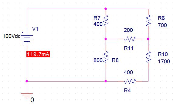
Copyright © 2017 McGraw-Hill Education. All rights reserved. No reproduction or distribution without the prior written consent of McGraw-Hill Education.
Solution 2.56
We need to find R eq and apply voltage division. We first transform the Y network to ∆ .
R ac = 450/(10) = 45Ω , R bc = 450/(15) = 30Ω
Combining the resistors in parallel,
= (600/50) = 12 Ω ,
= (37.5x30/67.5) = 16.667 Ω 35||45 = (35x45/80) = 19.688 Ω
eq = 19.688||(12 + 16.667) = 11.672Ω
Copyright © 2017 McGraw-Hill Education. All rights reserved. No reproduction or distribution without the prior written consent of McGraw-Hill Education.
Solution 2.57
Find R eq and I in the circuit of Fig. 2.121.
Figure 2.121 For Prob. 2.57. Solution
Copyright © 2017 McGraw-Hill Education. All rights reserved. No reproduction or distribution without the prior written consent of McGraw-Hill Education.
Combining resistors in parallel,
Checking with PSpice we get,

Copyright © 2017 McGraw-Hill Education. All rights reserved. No reproduction or distribution without the prior written consent of McGraw-Hill Education.
Solution 2.58
The 150 W light bulb in Fig. 2.122 is rated at 110 volts. Calculate the value of V s to make the light bulb operate at its rated conditions.
Figure 2.112 For Prob. 2.58.
Solution
Step 1. First we need to calculate the value of the resistance of the lightbulb. 150 = (110)2/R or R = (110)2/150. Now we have an equivalent circuit as shown below.
Next we note that V R = 110 volts. The equivalent parallel resistance is equal to 100R/(100+R) = R eq . Now we have a simple voltage divider or 110 = V s [R eq /(R eq +50)] and V s = 110(R eq +50)/R eq .
Step 2. R = 80.667 and R eq = 8066.7/180.667 = 44.65. This leads to, V s = 110(94.65)/44.65 = 233.2 volts
Copyright © 2017 McGraw-Hill Education. All rights reserved. No reproduction or distribution without the prior written consent of McGraw-Hill Education.
Solution 2.59
An enterprising young man travels to Europe carrying three lightbulbs he had purchased in North America. The lightbulbs he has are a 100 watt lightbulb, a 60 watt lightbulb, and a 40 watt lightbulb. Each lightbulb is rated at 110 volts. He wishes to connect these to a 220 volt system that is found in Europe. For reasons we are not sure of, he connects the 40 watt lightbulb in series with a parallel combination of the 60 watt lightbulb and the 100 watt lightbulb as shown Fig. 2.123. How much power is actually being delivered to each lightbulb? What does he see when he first turns on the lightbulbs?
Is there a better way to connect these lightbulbs in order to have them work more effectively?
100 Watt
40 Watt
60 Watt
Figure 2.123 For Prob. 2.59.
Solution
Step 1. Using p = v2/R, we can calculate the resistance of each bulb.
R 40W = (110)2/40
R 60W = (110)2/60
R 100W = (110)2/100
The total resistance of the series parallel combination of the bulbs is
R Tot = R 40W + R 100W R 60W /(R 100W + R 60W ).
We can now calculate the voltage across each bulb and then calculate the power delivered to each. V 40W = (220/R Tot )R 40W and the voltage across the other two, V 60||100 , will equal 220 – V 40W . P 40W = (V 40W )2/R 40W , P 60W = (V 60||100 )2/R 60W , and P 100W = (V 60||100 )2/R 100W .
Step 2.
R 40W = (110)2/40 = 12,100/40 = 302.5 Ω
R 60W = (110)2/60 = 12,100/60 = 201.7 Ω
Copyright © 2017 McGraw-Hill Education. All rights reserved. No reproduction or distribution without the prior written consent of McGraw-Hill Education.
R 100W = (110)2/100 = 12,100/100 = 121 Ω
R Tot = 302.5 + 121x201.7/(121+201.7) = 302.5 + 24,406/322.7 = 302.5+75.63 = 378.1 Ω.
V 40W = (220/R Tot )R 40W = 0.5819x302.5 = 176 volts and the voltage across the other two, V 100||40 , will equal 220 – V 40W = 44 volts. P 40W = (V 40W )2/R 40W = 30976/302.5 = 102.4 watts, P 60W = (V 60||100 )2/R 60W = 1936/201.7 = 9.6 watts, and P 100W = (V 60||100 )2/R 100W = 1936/121 = 16 watts.
Clearly when he flips the switch to light the bulbs the 40 watt bulb will flash bright as it burns out! Not a good thing to do!
Is there a better way to connect them? There are two other possibilities. However what if we place the bulb with the lowest resistance in series with a parallel combination of the other two what happens? Logic would dictate that this might give the best result. So, let us try the 100 watt bulb in series with the parallel combination of the other two as shown below.
40 Watt
100 Watt
60 Watt
Now we get, R Tot = 121 + 302.5x201.7/(302.5+201.7) = 121 + 61,014/504.2 = 121+121.01 = 242 Ω. Without going further we can see that this will work since the resistances are essentially equal which means that each bulb will work as if they were individually connected to a 110 volt system.
V 100W = (220/R Tot )121 = 110 and the voltage across the other two, V 60||40 , will equal 220 – V 100W = 110. P 100W = (V 100W )2/121 = 100 watts, P 60W = (V 60||40 )2/201.7 = 60 watts, and P 40W = (V 60||40 )2/302.5 = 40 watts This will work!
Answer: P 40W = 102.4 W (means that this immediately burns out), P 60W = 9.6 W, P 100W = 16 W. The best way to wire the bulbs is to connect the 100 W bulb in series with a parallel combination of the 60 W bulb and the 40 W bulb.
Copyright © 2017 McGraw-Hill Education. All rights reserved. No reproduction or distribution without the prior written consent of McGraw-Hill Education.
Solution 2.60
If the three bulbs of Prob. 2.59 are connected in parallel to the 120-V source, calculate the current through each bulb.
Solution
Using p = v2/R, we can calculate the resistance of each bulb.
R 30W = (120)2/30 = 14,400/30 = 480 Ω
R 40W = (120)2/40 = 14,400/40 = 360 Ω
R 50W = (120)2/50 = 14,400/50 = 288 Ω
The current flowing through each bulb is 120/R.
i 30 = 120/480 = 250 mA
i 40 = 120/360 = 333.3 mA
i 30 = 120/288 = 416.7 mA
Unlike the light bulbs in 2.59, the lights will glow brightly!
Copyright © 2017 McGraw-Hill Education. All rights reserved. No reproduction or distribution without the prior written consent of McGraw-Hill Education.
Solution 2.61
There are three possibilities, but they must also satisfy the current range of 1.2 + 0.06 = 1.26 and 1.2 – 0.06 = 1.14.
(a) Use R 1 and R 2 :
R = Ω = = 42.35 90 80 R R 2 1
p = i2R = 70W
i2 = 70/42.35 = 1.6529 or i = 1.2857 (which is outside our range)
cost = $0.60 + $0.90 = $1.50
(b) Use R 1 and R 3 :
R = Ω = = 44.44 100 80 R R 3 1 i2 = 70/44.44 = 1.5752 or i = 1.2551 (which is within our range),
cost = $1.35
(c) Use R 2 and R 3 :
R = Ω = = 47.37 100 90 R R 3 2 i2 = 70/47.37 = 1.4777 or i = 1.2156 (which is within our range),
cost = $1.65
Note that cases (b) and (c) satisfy the current range criteria and (b) is the cheaper of the two, hence the correct choice is:
R 1 and R 3
Copyright © 2017 McGraw-Hill Education. All rights reserved. No reproduction or distribution without the prior written consent of McGraw-Hill Education.
Solution 2.62
p A = 110x8 = 880 W, p B = 110x2 = 220 W
Energy cost = $0.06 x 365 x10 x (880 + 220)/1000 = $240.90
Copyright © 2017 McGraw-Hill Education. All rights reserved. No reproduction or distribution without the prior written consent of McGraw-Hill Education.
Solution 2.63
Use eq. (2.61),
Copyright © 2017 McGraw-Hill Education. All rights reserved. No reproduction or distribution without the prior written consent of McGraw-Hill Education.
Solution 2.64
The potentiometer (adjustable resistor) R x in Fig. 2.126 is to be designed to adjust current I x from 10 mA to 1 A. Calculate the values of R and R x to achieve this.
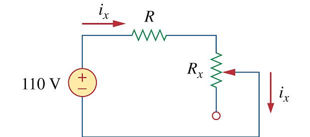
Figure 2.126 For Prob. 2.64.
Solution
Step 1. Even though there are an infinite number of combinations that can meet these requirements, we will focus on making the potentiometer the most sensitive.
First we will determine the value of R by setting the potentiometer equal to zero. i x = 110/R = 1 A. Next we set the potentiometer to its maximum value or 0.01 = 110/(R+R x ) or R x = (110/0.01) – R. We now have enough equations to solve for R and R x .
Step 2. R = 110 Ω and R x = 11,000 – 110 = 10.89 kΩ.
Copyright © 2017 McGraw-Hill Education. All rights reserved. No reproduction or distribution without the prior written consent of McGraw-Hill Education.
Solution 2.65
Design a circuit that uses a d’Arsonval meter (with an internal resistance of 2 kΩ that requires a current of 5 mA to cause the meter to deflect full scale) to build a voltmeter to read values of voltages up to 100 volts.
Solution.
Step 1. Since 100 volts across the meter will cause the current through the meter to be 100/2,000 = 0.05 amps, a way must be found to limit the current to 0.005 amps. Clearly adding a resistance in series with the meter will accomplish that. The value of the resistance can be found by solving for 100/R Tot = 0.005 amps where R Tot = 2,000 + R s
Step 2. R Tot = 100/0.005 = 20 kΩ. R s = 20,000 – 2,000 = 18 kΩ. So, our circuit consists of the meter in series with an 18 kΩ resistor.
Copyright © 2017 McGraw-Hill Education. All rights reserved. No reproduction or distribution without the prior written consent of McGraw-Hill Education.
Solution 2.66 20 kΩ /V = sensitivity = fs I 1
i.e., I fs = A 50 V / k 20 1 µ = Ω
Copyright © 2017 McGraw-Hill Education. All rights reserved. No reproduction or distribution without the prior written consent of McGraw-Hill Education.
Solution 2.67
(a) By current division, i 0 = 5/(5 + 5) (2 mA) = 1 mA V 0 = (4 kΩ ) i 0 = 4 x 103 x 10-3 = 4 V
(b) . k2.4 k6 k4 Ω = By current division,
Copyright © 2017 McGraw-Hill Education. All rights reserved. No reproduction or distribution without the prior written consent of McGraw-Hill Education.
Copyright © 2017 McGraw-Hill Education. All rights reserved. No reproduction or distribution without the prior written consent of McGraw-Hill Education.
Solution 2.69
A voltmeter is used to measure V o in the circuit in Fig. 2.129. The voltmeter model consists of an ideal voltmeter in parallel with a 250-kΩ resistor. Let V s = 95 V, R s = 25 kΩ , and R 1 = 40 kΩ . Calculate V o with and without the voltmeter when
(a) R 2 = 5 kΩ (b) R 2 = 25 kΩ
(c) R 2 = 250 kΩ
Solution
Figure 2.129 For Prob. 2.69
Step 1. V o = and V o =


Step 2. (a) V o = = 95(4.902/69.902) = 6.662 volts and
V o = = 95(5k/70k) = 6.786 volts

(b) V o = = 95(22.727/87.727) = 24.61 volts and V o = = 95(25/90) = 26.39 volts
(c) V o = = 95(125/190) = 62.5 volts and V o = = 95(250/315) = 75.4 volts
Copyright © 2017 McGraw-Hill Education. All rights reserved. No reproduction or distribution without the prior written consent of McGraw-Hill Education.
Solution 2.70
(a) Using voltage division,
v V a = + = 12 12 8 25 15 ( )
v V b = + = 10 10 15 25 10 ( )
v v v V ab a b = = = 15 10 5
(b) c +
v a = 0; v ac = –(8/(8+12))25 = –10V; v cb = (15/(15+10))25 = 15V.
v ab = v ac + v cb = –10 + 15 = 5V.
v b = –v ab = –5V.
Copyright © 2017 McGraw-Hill Education. All rights reserved. No reproduction or distribution without the prior written consent of McGraw-Hill Education.
Solution 2.71
Figure 2.131 represents a model of a solar photovoltaic panel. Given that V s = 95 V, R 1 = 25 Ω , i L = 2 A, find R L .
Figure 2.131 For Prob. 2.71.
Step 1. V s = i L (R 1 +R L ) or R L = (95/2) – 25
Step 2. R L = 47.5 – 25 = 22.5 Ω
Copyright © 2017 McGraw-Hill Education. All rights reserved. No reproduction or distribution without the prior written consent of McGraw-Hill Education.
Solution 2.72
Converting the delta subnetwork into wye gives the circuit below.
Copyright © 2017 McGraw-Hill Education. All rights reserved. No reproduction or distribution without the prior written consent of McGraw-Hill Education.
Solution 2.73
By the current division principle, the current through the ammeter will be one-half its previous value when
R = 20 + R x 65 = 20 + R x R x = 45 Ω
Copyright © 2017 McGraw-Hill Education. All rights reserved. No reproduction or distribution without the prior written consent of McGraw-Hill Education.
Solution 2.74
With the switch in high position,
6 = (0.01 + R 3 + 0.02) x 5 R 3 = 1.17 Ω
At the medium position,
6 = (0.01 + R 2 + R 3 + 0.02) x 3 R 2 + R 3 = 1.97 or R 2 = 1.97 - 1.17 = 0.8 Ω
At the low position,
6 = (0.01 + R 1 + R 2 + R 3 + 0.02) x 1
1 + R 2 + R 3 = 5.97 R 1 = 5.97 - 1.97 = 4 Ω
Copyright © 2017 McGraw-Hill Education. All rights reserved. No reproduction or distribution without the prior written consent of McGraw-Hill Education.
Solution 2.75
Find R ab in the four-way power divider circuit in Fig. 2.135. Assume each R = 4 Ω .
Figure 2.135 For Prob. 2.75.
Step 1. There are two delta circuits that can be converted to a wye connected circuit. This then allows us to combine resistances together in series and in parallel. This will yield a new circuit with one remaining delta connected circuit that can be converted to a wye connected circuit which then can be reduced to R ab .
Copyright © 2017 McGraw-Hill Education. All rights reserved. No reproduction or distribution without the prior written consent of McGraw-Hill Education.
Step 2. Converting delta-subnetworks to wye-subnetworks and combining resistances leads to the circuit below. = R
With this combination, the circuit is further reduced to that shown below.
Again we convert the delta to a wye connected circuit and the values of the wye resistances are all equal to R/3 and combining all the series and parallel resistors gives us R in series with R. Thus,
ab = R+R = 4+4 = 8 Ω
Copyright © 2017 McGraw-Hill Education. All rights reserved. No reproduction or distribution without the prior written consent of McGraw-Hill Education.
Solution 2.76
Z ab = 1 + 1 = 2 Ω
Copyright © 2017 McGraw-Hill Education. All rights reserved. No reproduction or distribution without the prior written consent of McGraw-Hill Education.
Solution 2.77
(a) 5 Ω = 20 20 20 20 10 10 =
i.e., four 20 Ω resistors in parallel.
(b) 311.8 = 300 + 10 + 1.8 = 300 + 1.8 20 20 +
i.e., one 300Ω resistor in series with 1.8Ω resistor and a parallel combination of two 20Ω resistors.
(c) 40kΩ = 12kΩ + 28kΩ = ) 56 (56 ) 24 24 ( k k k +
i.e., Two 24kΩ resistors in parallel connected in series with two 56kΩ resistors in parallel.
(d) 52.32kΩ = 28k+24k+300+20 = 56k||56k+24k+300+20
i.e., A series combination of a 20Ω resistor, 300Ω resistor, 24kΩ resistor, and a parallel combination of two 56kΩ resistors.
Copyright © 2017 McGraw-Hill Education. All rights reserved. No reproduction or distribution without the prior written consent of McGraw-Hill Education.
Solution 2.78
The equivalent circuit is shown below:
Copyright © 2017 McGraw-Hill Education. All rights reserved. No reproduction or distribution without the prior written consent of McGraw-Hill Education.
Solution 2.79
Since p = v2/R, the resistance of the sharpener is
R = v2/(p) = 62/(240 x 10-3) = 150Ω
I = p/(v) = 240 mW/(6V) = 40 mA
Since R and R x are in series, I flows through both.
IR x = V x = 9 - 6 = 3 V
R x = 3/(I) = 3/(40 mA) = 3000/(40) = 75 Ω
Copyright © 2017 McGraw-Hill Education. All rights reserved. No reproduction or distribution without the prior written consent of McGraw-Hill Education.
Solution 2.80
The amplifier can be modeled as a voltage source and the loudspeaker as a resistor:
Copyright © 2017 McGraw-Hill Education. All rights reserved. No reproduction or distribution without the prior written consent of McGraw-Hill Education.
Solution 2.81
For a specific application, the circuit shown in Fig. 2.140 was designed so that I L = 83.33 mA and that R in = 5 kΩ. What are the values of R 1 and R 2 ?
Figure 2.140 For Prob. 2.81.
Solution
Step 1. Calculate R in in terms of R 1 and R 2 . Next calculate the value of I L in terms of R 1 and R 2 .
= 5k and since R in = 5k, the current by current
division entering R in has to equal 500 mA. Again using current division, the current through R 1 = 250 mA. Finally we can use current division to obtain I L
I L = 0.25xR 2 /(R 2 +10k) = 0.08333 A.
Step 2. First we can calculate R 2 . 0.25R 2 = 0.08333(R 2 + 10,000) or (0.25–0.08333)R 2 = 833.3 or R 2 = 833.3/0.16667 = 5,000 = 5 kΩ.
Next 5k =
10kR 5k10k kx
5k(R 1 +13.3333k) = 10k(R 1 +3.3333) or R 1 +13.3333 = 2R 1 + 6.6666 or R 1 = 13.3333k–6.6666k = 6.6667k = 6.667 kΩ.
Copyright © 2017 McGraw-Hill Education. All rights reserved. No reproduction or distribution without the prior written consent of McGraw-Hill Education.
Solution 2.82
The pin diagram of a resistance array is shown in Fig. 2.141. Find the equivalent resistance between the following:
(a) 1 and 2 (b) 1 and 3 (c) 1 and 4
Figure 2.141 For Prob. 2.82.
Solution
Step 1. Each pair of contacts will connect a specific circuit where we can use the variety of wye-delta, series, and paralleling of resistances to obtain the desired results.
Copyright © 2017 McGraw-Hill Education. All rights reserved. No reproduction or distribution without the prior written consent of McGraw-Hill Education.
Step 2. (a) R 12 = 75 + 30x60/(30+60) = 75+20 = 95 Ω
(b) R 13 = 75 + [30x60/(30+60)] + 40 = 135 Ω
(c) R 14 = 40 + 75 = 105 Ω
Copyright © 2017 McGraw-Hill Education. All rights reserved. No reproduction or distribution without the prior written consent of McGraw-Hill Education.
Solution 2.83
Two delicate devices are rated as shown in Fig. 2.142. Find the values of the resistors R 1 and R 2 needed to power the devices using a 36-V battery.

Figure 2.142 For Prob. 2.83.
Solution
The voltage across the fuse should be negligible when compared with 24 V (this can be checked later when we check to see if the fuse rating is exceeded in the final circuit). We can calculate the current through the devices.
Let R 3 represent the resistance of the first device, we can solve for its value from knowing the voltage across it and the current through it. R 3 = 12/0.00625 = 1,920 Ω
Copyright © 2017 McGraw-Hill Education. All rights reserved. No reproduction or distribution without the prior written consent of McGraw-Hill Education.
This is an interesting problem in that it essentially has two unknowns, R 1 and R 2 but only one condition that need to be met and that is that the voltage across R 3 must equal 12 volts. Since the circuit is powered by a battery we could choose the value of R 2 which draws the least current, R 2 = ∞. Thus we can calculate the value of R 1 that gives 12 volts across R 3 .
12 = (36/(R 1 + 1920))1920 or R 1 = (36/12)1920 – 1920 = 3.84 kΩ
This value of R 1 means that we only have a total of 26.25 mA flowing out of the battery through the fuse which means it will not open and produces a voltage drop across it of 0.0525 mV. This is indeed negligible when compared with the 36-volt source.
Copyright © 2017 McGraw-Hill Education. All rights reserved. No reproduction or distribution without the prior written consent of McGraw-Hill Education.
Saturday, December 20, 2014
CHAPTER 2
P.P.2.1 i = V/R = 110/15 = 7.333 A
P.P.2.2
(a) v = iR = 3 mA[10 kohms] = 30 V
(b) G = 1/R = 1/10 kohms = 100 µS
(c) p = vi = 30 volts[3 mA] = 90 mW
P.P.2.3 p = vi which leads to i = p/v = [30 cos2 (t) mW]/[15cos(t) mA] or i = 2cos(t) mA
R = v/i = 15cos(t)V/2cos(t)mA = 7.5 k
P.P.2.4 5 branches and 3 nodes. The 1 ohm and 2 ohm resistors are in parallel. The 4 ohm resistor and the 10 volt source are also in parallel.
P.P.2.5 Applying KVL to the loop we get:
–32 + 4i – (–8) + 2i = 0 which leads to i = 24/6 = 4A v1 = 4i = 16 V and v2 = –2i = –8 V
P.P.2.6 Applying KVL to the loop we get:
–70 + 10i + 2vx + 5i = 0
But, vx = 10i and v0 = –5i. Hence,
–70 + 10i + 20i + 5i = 0 which leads to i = 2 A.
Thus, vx = 20V and v0 = –10 V
Copyright © 2017 McGraw-Hill Education. All rights reserved. No reproduction or distribution without the prior written consent of McGraw-Hill Education.
P.P.2.7
Applying KCL, 0 = –15 + i0 + [i0 /3] + [v0 /12], but i0 = v0/2
Which leads to: 15 = (v0/2) + (v0/6) + (v0/12) = vo((6+2+1)/12) thus, v0 = 20 V and i0 = 10 A
P.P.2.8

At the top node, 0 = –i1 + i2 + i3 or i1 = i2 + i3 (1)
For loop 1 –10 + V1 + V2 = 0 or V1 = 10 – V2 (2) For loop 2 – V2 + V3 – 6 = 0 or V3 = V2 + 6 (3)
Using (1) and Ohm’s law, we get (V
and now using (2) and (3) in the above yields [(10 – V
+ (V2 + 6)/4 or [7/8]V2 = 14/4 or V2 = 4 V


Copyright © 2017 McGraw-Hill Education. All rights reserved. No reproduction or distribution without the prior written consent of McGraw-Hill Education.
Combining the 8-ohm, 10-ohm, and 6-ohm resistors in series gives 8+10+6 = 24.
But, 12 in parallel with 24 produces [12x24]/[12+24] = 288/36 = 8 ohms.
So that the equivalent circuit is shown below.
Thus, Req = 4 + [6x12]/[6+12] + 3 = 11
P.P.2.10

Combining the 9 ohm resistor and the 18 ohm resistor yields [9x18]/[9+18] = 6 ohms.
Copyright © 2017 McGraw-Hill Education. All rights reserved. No reproduction or distribution without the prior written consent of McGraw-Hill Education.
Combining the 5 ohm and the 20 ohm resistors in parallel produces [5x20/(5+20)] = 4 ohms We now have the following circuit:


The 4 ohm and 1 ohm resistors can be combined into a 5 ohm resistor in parallel with a 20 ohm resistor. This will result in [5x20/(5+20)] = 4 ohms and the circuit shown below:
The 4 ohm and 2 ohm resistors are in series and can be replaced by a 6 ohm resistor. This gives a 6 ohm resistor in parallel with a 6 ohm resistor, [6x6/(6+6)] = 3 ohms. We now have a 3 ohm resistor in series with a 16 ohm resistor or 3 + 16 = 19 ohms.
Therefore: P.P. 2.11


12 S in series with 24 S = {12x24/(12+24)] = 8 or:
Copyright © 2017 McGraw-Hill Education. All rights reserved. No reproduction or distribution without the prior written consent of McGraw-Hill Education.
P.P.2.12
6||12 = [6x12/(6+12)] = 4 ohm and 10||40 = [10x40/(10+40)] = 8 ohm.
Using voltage division we get:
v1 = [4/(4+8)] (30) = 10 volts, v2 = [8/12] (30) = 20 volts
i1 = v1/12 = 10/12 = 833.3 mA, i2 = v2/40 = 20/40 = 500 mA P1 = v1 i1 = 10x10/12 = 8.333 watts, P2 = v2 i2 = 20x0.5 = 10 watts
P.P.2.13
Using current division, i1 = i2 = (30 mA)(12 kohm/(12 kohm + 12 kohm)) = 15mA
(a) v1 = (9 kohm)(15 mA) = 135 volts v2 = (12 kohm)(15 mA) = 180 volts
(b) For the 9k ohm resistor, P1 = v1 x i1 = 135x15x10–3 = 2.025 w For the 60k ohm resistor, P2 = (v2)2 /60k = 540 mw
(c) The total power supplied by the current source is equal to: P = v2 x 30 mA = 180x30x10–3 = 5.4 W
Copyright © 2017 McGraw-Hill Education. All rights reserved. No reproduction or distribution without the prior written consent of McGraw-Hill Education.
P.P.2.14
Ra = [R1 R2 + R2 R3 + R3 R1]/ R1 = [10x20 + 20x40 + 40x10]/10 = 140 ohms
Rb = [R1 R2 + R2 R3 + R3 R1]/ R2 = 1400/20 = 70 ohms
Rc = [R1 R2 + R2 R3 + R3 R1]/ R3 = 1400/40 = 35 ohms
P.P.2.15 We first find the equivalent resistance, R. We convert the delta sub-network to a wye connected form as shown below:


Ra’n = 40x60/[40 + 60 + 100] = 12 ohms, Rb’n = 40x100/200 = 20 ohms
Rc’n = 60x100/200 = 30 ohms.
Thus, Rab = 6 + [(48 + 12)||(20 + 20)] + 30 = 6 + 60x40/(60 + 40) + 30
6 + 24 + 30 = 60 ohms.
i = 240/ Rab = 240/60 = 4 amps
P.P.2.16 For the parallel case, v = v0 = 115volts. p = vi i = p/v = 40/115 = 347.8 mA
For the series case, v = v0/N = 115/6 = 19.167 volts i = p/v = 40/19.167 = 2.087 amps
P.P.2.17 We use equation (2.61)
(a) R1 = 50x10-3/ (1-10-3) = 0.05/999 = 50 mΩ (shunt)
(c) R3 = 50x10-3/(10x10-3-10-3) = 50/9 = 5.556 Ω (shunt)+ i
(b) R2 = 50x10-3/(100x10-3 – 10-3) = 50/99 = 505 mΩ (shunt)
Copyright © 2017 McGraw-Hill Education. All rights reserved. No reproduction or distribution without the prior written consent of McGraw-Hill Education.