Chapter 1: Fundamentals of Electrical Circuits – Instructor Notes
Chapter 1 develops the foundations for the first part of the book. Coverage of the entire chapter would be typical in an introductory course. The first four sections provide the basic definitions (Section 1.1) and cover Kirchhoff’s Laws, instantaneous power and the passive sign convention (Sections 1.2, 1.3 and 1.4); A special feature, Focus on Problem Solving: The Passive Sign Convention (p. 22) and ten examples illustrate these important topics. A second feature, that will recur throughout the first six chapters, is presented in the form of sidebars. Make The Connection: Hydraulic Analog of a Voltage Source (p. 28) and Make The Connection: Hydraulic Analog of a Current Source (p. 29) present the concept of analogies between electrical and other physical domains.
Sections 1.5 and 1.6 introduce the i-v characteristic and the resistance element. Tables 1.1 (p. 31) and 1.2 and 1.3 (p. 33) summarize the resistance of copper wire for various gauges, the resistivity of common materials and standard resistor values, respectively. The sidebar Make The Connection: Hydraulic Analog of Electrical Resistance (p. 31) continues the electrichydraulic system analogy.
Sections 1.7 and 1.8 introduce the critically important concepts of elements in series and parallel and the associated analytic methods of voltage and current division. Section 1.8 introduces another special feature of the book, the Focus on Measurements box. The first three of these boxes appear at the end of that section and are focused on practical aspects of a Resistive Throttle Position Sensor, Resistance Strain Gauges, and The Wheatstone Bridge and Force Measurements These three boxes demonstrate the common role of voltage division in the construction of electrical sensors.
Finally, Sections 1.9 and 1.10 introduce basic but important concepts related to ideal and non-ideal models of practical sources, and common measuring instruments.
The Instructor will find that although the material in Chapter 1 is quite basic, it is possible to give an applied flavor to the subject matter by emphasizing a few selected topics in the examples presented in class. In particular, a lecture could be devoted to resistance devices, including the resistive displacement transducer of Focus on Measurements: Resistive Throttle Position Sensor (pp. 46-47), the resistance strain gauge of Focus on Measurements: Resistance Strain Gauges (p. 48), and Focus on Measurements: The Wheatstone Bridge and Force Measurements (pp. 49-50). The instructor wishing to gain a more in-depth understanding of resistance strain gauges can find detailed analyses in many common references.
Early motivation for the application of circuit analysis to problems of practical interest to the non-electrical engineer can be found in these Focus on Measurements boxes. The Wheatstone bridge material can also serve as an introduction to a laboratory experiment on strain gauges and the measurement of force. Finally, Example 1.16 on the Impact of a Practical Voltmeter at the end of Section 1.10 describes a quick but interesting laboratory experiment.
The homework problems include a variety of practical examples, with emphasis on instrumentation. Problem 1.39 illustrates the result of placing two practically equivalent batteries in parallel; problems 1.43 relates to wire gauges; problem 1.44 discusses one common
Copyright 2022 © McGraw Hill LLC. All rights reserved. No reproduction or distribution without the prior written consent of McGraw Hill LLC.
Rizzoni and Kearns, Fundamentals of
method of resistor construction; problem 1.45 illustrates analysis related to fuses; problem 1.53 introduces the thermistor; problem 1.54 discusses circuit design involving a moving coil meter; problem 1.57 describes a procedure for measuring the internal resistance of an ammeter; problem 1.60 illustrates the potential loading effect of a practical voltmeter; and problems 1.62 and 1.63 illustrate calculations related to strain gauge bridges.
It has been the author's experience that providing the students with an early introduction to practical applications of electrical engineering to their own disciplines can increase the interest level in a course significantly.
Learning Objectives for Chapter 1
Students will learn to…
1. Identify the principal features of electric circuits or networks: nodes, loops, meshes, and branches. Section 1.1
2. Apply Kirchhoff’s Laws to simple electrical circuits. Sections 1.2-1.3
3. Apply the passive sign convention to compute the power consumed or supplied by circuit elements. Section 1.4.
4. Identify sources and resistors and their i-υ characteristics. Sections 1.5–1.6
5. Apply Ohm’s law and voltage and current division to calculate unknown voltages and currents in simple series, parallel, and series-parallel circuits. Sections 1.6–1.8
6. Understand the impact of internal resistance in practical models of voltage and current sources as well as of voltmeters, ammeters, and wattmeters. Sections 1.9–1.10
Copyright 2022 © McGraw Hill LLC. All rights reserved. No reproduction or distribution without the prior written consent of McGraw Hill LLC.
Rizzoni and Kearns, Fundamentals of Electrical Engineering, 2nd Edition Problem solutions, Chapter 1
Sections 1.2-1.3: Charge, Current, and Kirchhoff’s Current Law; Voltage and Kirchhoff’s Voltage Law
Problem 1.1
A free electron has an initial potential energy per unit charge (voltage) of 17 kJ/C and a velocity of 93 Mm/s. Later, its potential energy per unit charge is 6 kJ/C. Determine the change in velocity of the electron.
Solution:
Known quantities:
Find:
The change in velocity of the electron.
Initial Coulombic potential energy, Vi =17kJ/C ; initial velocity, Ui = 93M m s ; final Coulombic potential energy, Vf = 6kJ /C
Assumptions:
PEg PEc
Analysis:
Using the first law of thermodynamics, we obtain the final velocity of the electron:
Qheat W = KE + PEc + PEg + Heat is not applicable to a single particle. W=0 since no external forces are applied.
KE = PEc
1 2
Copyright 2022 © McGraw Hill LLC. All rights reserved. No reproduction or distribution without the prior written consent of McGraw Hill LLC.
Rizzoni and Kearns, Fundamentals of Electrical Engineering, 2nd Edition Problem solutions, Chapter 1
Problem 1.2
The units for voltage, current, and resistance are the volt (V), the ampere (A), and the ohm (), respectively. Express each unit in fundamental MKS units.
Solution:
Known quantities: MKSQ units.
Find:
Equivalent units of volt, ampere and ohm.
Analysis:
Voltage = Volt = Joule Coulomb V = J C
Current = Ampere = Coulomb second a = C s
Resistance = Ohm = Volt Ampere = Joule second Coulomb2 = J s C2
Conductance = Siemens or Mho = Ampere Volt = C2 J s
Problem 1.3
A particular fully charged battery can deliver 2.7 x 10⁶ coulombs of charge. a. What is the capacity of the battery in ampere-hours? b. How many electrons can be delivered?
Solution:
Known quantities: qBattery = 2.7 · 106 C.
Find:
The current capacity of the battery in ampere-hours The number of electrons that can be delivered.
Analysis:
There are 3600 seconds in one hour. Amperage is defined as 1 Coulomb per second and is directly proportional to ampere-hours.
a) The charge of a single electron is -1.602·10-19 C. The negative sign is negligible. Simple division gives the solution: 27∙106��
Copyright 2022 © McGraw Hill LLC. All rights reserved. No reproduction or distribution without the prior written consent of McGraw Hill LLC.
Problem 1.4
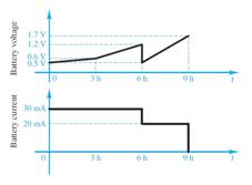
The charge cycle shown in Figure P1.4 is an example of a three-rate charge. The current is held constant at 30 mA for 6 h. Then it is switched to 20 mA for the next 3 h. Find:
a. The total charge transferred to the battery. b. The energy transferred to the battery. Hint: Recall that energy w is the integral of power, or P = dw/dt.
Solution:
Known quantities:
See Figure P1.4
Find:
a) The total charge transferred to the battery.
b) The energy transferred to the battery.
Analysis:
Current is equal to ���������������� ������������ , therefore given the current and a duration of that current, the transferred charge can be calculated by the following equation: ��∙�� =��
The two durations should be calculated independently and then added together.
0.030��∙21600��=648��
0.020��∙10800��=216�� 648��+216�� =��������
P=V·I, therefore, an equation for power can be found by multiplying the two graphs together. First separate the voltage graph into three equations:
0 h → 3 h :�� =9.26·10 6��+0.5
3 h → 6 h :�� =5.55 10 5��
6 h → 9 h :�� =1.11∙10 4�� 1.6
Next, multiply the first two equations by 0.03A and the third by 0.02A.
0 h → 3 h :�� =2.77∙10 7��+0.015
3 h → 6 h :�� =1.66∙10 6��
6 h → 9 h :�� =2.22∙10 6�� 0.032
Finally, since Energy is equal to the integral of power, take the integral of each of the equations for their specified times and add them together.
0 h → 3 h :�� =[27710 7��2 2 +0.015��]|10800 0 = 178.2 J
3 h → 6 h :�� =[1.6610 6��2 2 ]|21600 10800= 290.43 J
6 h → 9 h :�� =[222∙10 6��2 2 +0.032��]|32400 21600 = 992.95 J ������������ =����������
Copyright 2022 © McGraw Hill LLC. All rights reserved. No reproduction or distribution without the prior written consent of McGraw Hill LLC.
Problem 1.5
Batteries (e.g., lead-acid batteries) store chemical energy and convert it to electric energy on demand. Batteries do not store electric charge or charge carriers. Charge carriers (electrons) enter one terminal of the battery, acquire electrical potential energy, and exit from the other terminal at a lower voltage. Remember the electron has a negative charge! It is convenient to think of positive carriers flowing in the opposite direction, that is, conventional current, and exiting at a higher voltage. All currents in this course, unless otherwise stated, are conventional current. (Benjamin Franklin caused this mess!) For a battery with a rated voltage = 12 V and a rated capacity = 350 A-h, determine
a. The rated chemical energy stored in the battery.
b. The total charge that can be supplied at the rated
Solution:
Known quantities:
Rated voltage of the battery; rated capacity of the battery.
Find:
The rated chemical energy stored in the battery
The total charge that can be supplied at the rated voltage.
Analysis:
t ( ) = 12 V 350A hr 3600 s hr = 15 12 MJ
As the battery discharges, the voltage will decrease below the rated voltage. The remaining chemical energy stored in the battery is less useful or not useful. b) Q is the total charge passing through the battery and gaining 12 J/C of electrical energy.
Q = I t = 350 a hr = 350 C s hr 3600 s hr = 1 26 MC
Problem 1.6
What determines:
a. The current through an ideal voltage source?
b. The voltage across an ideal current source?
Copyright 2022 © McGraw Hill LLC. All rights reserved. No reproduction or distribution without the prior written consent of McGraw Hill LLC.
Solution:
Known quantities:
Resistance of external circuit.
Find:
Current supplied by an ideal voltage source
Voltage supplied by an ideal current source.
Assumptions:
Ideal voltage and current sources.
Analysis:
a) An ideal voltage source produces a constant voltage at or below its rated current. Current is determined by the power required by the external circuit (modeled as R).
b) An ideal current source produces a constant current at or below its rated voltage. Voltage is determined by the power demanded by the external circuit (modeled as R).
A real source will overheat and, perhaps, burn up if its rated power is exceeded.
Problem 1.7
An automotive battery is rated at 120 A-h. This means that under certain test conditions it can output 1 A at 12 V for 120 h (under other test conditions, the battery may have other ratings).
a. How much total energy is stored in the battery?
b. If the headlights are left on overnight (8 h), how much energy will still be stored in the battery in the morning? (Assume a 150-W total power rating for both headlights together.)
Solution:
Known quantities:
Rated discharge current of the battery; rated voltage of the battery; rated discharge time of the battery.
Find:
Energy stored in the battery when fully recharging
Energy stored in the battery after discharging
Analysis:
b) Assume that 150 W is the combined power rating of both lights; then,
Copyright 2022 © McGraw Hill LLC. All rights reserved. No reproduction or distribution without the prior written consent of McGraw Hill LLC.
Rizzoni and Kearns, Fundamentals
Problem 1.8
A car battery kept in storage in the basement needs recharging. If the voltage and the current provided bythe charger during a charge cycle are shown in FigureP1.8, a. Find the total charge transferred to the battery.
b. Find the total energy transferred to the battery.
Solution:
Known quantities:
Recharging current and recharging voltage
Find:
Total transferred charge
Total transferred energy
Analysis:

Copyright 2022 © McGraw Hill LLC. All rights reserved. No reproduction or distribution without the prior written consent of McGraw Hill LLC.
Problem 1.9
Suppose the current through a wire is given by the curve shown in Figure P1.9.
a. Find the amount of charge, q, that flows through the wire between t1 = 0 and t2 = 1 s.
b. Repeat part a for t2 = 2, 3, 4, 5, 6, 7, 8, 9, and 10 s.
c. Sketch q(t) for 0 ≤ t ≤ 10 s.
Solution:
Known quantities:
Current-time curve
Find:
Amount of charge during 1st second
Amount of charge for 2 to 10 seconds
Sketch charge-time curve
Analysis:
Q2 = 4 10 3 Coulombs
b) The charge transferred from t = 1 to

t = 2 is the same as from
t = 0 to
t = 1
The charge transferred from t = 2 to t = 3 is the same in magnitude and opposite in direction to that from

Problem 1.10
The charge cycle shown in Figure P2.10 is an example of a two-rate charge. The current is held constant at 70 mA for 1 h. Then it is switched to 60 mA for the next 1 h. Find:
a. The total charge transferred to the battery.
b. The total energy transferred to the battery.
Hint: Recall that energy w is the integral of power, or P = dw/dt. Let: ��
=5+��t/51948 ��
Solution:
Known quantities:
See Figure P1.10
Find:
a) The total charge transferred to the battery.
b) The energy transferred to the battery.
Analysis:

Current is equal to ���������������� ������������ , therefore given the current and a duration of that current, the transferred charge can be calculated by the following equation: ��∙�� =��
The two durations should be calculated independently and then added together.
0.070�� 3600��=252��
0060��∙3600��=216�� 648��+216�� =��������
P=V·I, therefore, an equation for power can be found by multiplying the two graphs together. First separate the voltage graph into three equations:
0 h → 1 h :�� =5+����⁄51948��
Copyright 2022 © McGraw Hill LLC. All rights reserved. No reproduction or distribution without the prior written consent of McGraw Hill LLC.
1 h → 2 h :�� =(6 4 ��1 1)+ 4 ��2 ��1 ∗������
Next, multiply the first equation by 0.07A and the second by 0.06A.
0 h → 1 h :�� =0.35+0.07����⁄51948
1 h → 2 h :�� =0.06(6 4 ��1ℎ 1)+0.06 4 ��2ℎ ��1ℎ ∗������
Finally, since Energy is equal to the integral of power, take the integral of each of the equations for their specified times and add them together.
0 h → 1 h :�� =[0.35��+363.64����⁄51948]|3600 0 = 1623.53 J
1 h → 2 h :�� =[0.36��+2.88∗10 3128 ∗2.72��]|7200 3600= 1296 24 J ������������ =��������.������
Problem 1.11
The charging scheme used in Figure P1.11 is an example of a constant-current charge cycle. The charger voltage is controlled such that the current into the battery is held constant at 40 mA, as shown in Figure P1.11. The battery is charged for 6 h. Find:
a. The total charge delivered to the battery.
b. The energy transferred to the battery during the charging cycle. Hint: Recall that the energy, w, is the integral of power, or P = dw/dt.
Solution:
Known quantities:
Current-time curve and voltage-time curve of battery recharging
Find:
Total transferred charge
Total transferred energy
Analysis:
a) A mA 0.04 40 =
Q = area under the current-time curve= Idt = 004 ( ) 6( ) 3600( ) = 864 C Q=864C
b) P dt dw = so

Copyright 2022 © McGraw Hill LLC. All rights reserved. No reproduction or distribution without the prior written consent of McGraw Hill LLC.
Problem 1.12
The charging scheme used in Figure P1.12 is called a taperedcurrent charge cycle. The current starts at the highest level and then decreases with time for the entire charge cycle, as shown. The battery is charged for 12 h. Find:
a. The total charge delivered to the battery.
b. The energy transferred to the battery during the charging cycle. Hint: Recall that the energy, w, is the integral of power, or P = dw/dt.
Solution:
Known quantities:
Current-time curve and voltage-time curve of battery recharging
Find:
Total transferred charge
Total transferred energy
Analysis:

Rizzoni
Kearns, Fundamentals
Problem 1.13
Use KCL to determine the unknown currents in Figure P1.13.

Solution:
Known quantities: io = 2 A, i2 = -7 A
Find:
Analysis:
a) Use KCL at the node between Ro ,R1, and R2
b) Use KCL at the node between R2 ,R3, and the current source.
Problem 1.14
Use KCL to find the currents i1 and i2 in Figure P1.14.

Copyright 2022 © McGraw Hill LLC. All rights reserved. No reproduction or distribution without the prior written consent of McGraw Hill LLC.
Rizzoni and Kearns, Fundamentals of
Solution:
Known
Find:
Analysis:
a) Use KCL at Node A.
b) Use KCL at Node B.
Problem 1.15
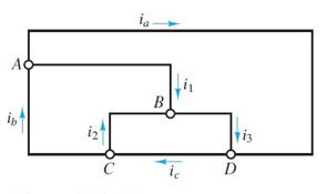
Use KCL to find the current i1, i2, and i3 in the circuit of Figure P1.15.
Solution:
Known quantities:
a = 2 mA, ib = 7 mA, ic = 4 mA
Find:
Copyright 2022 © McGraw Hill LLC. All rights reserved. No reproduction or distribution without the prior written consent of McGraw Hill LLC.
Rizzoni
Analysis:
Kearns, Fundamentals
a) Use KCL at Node A.
b) Use KCL at Node C.
c) Use KCL at Node D.
Problem 1.16
Use KVL to find the voltages v1,v2, and v3 in Figure P1.16.

Solution:
Known quantities:
Find:
Analysis: a) Use KVL at the third loop.
b) Use KVL at the second loop.
Copyright 2022 © McGraw Hill LLC. All rights reserved. No reproduction or distribution without the prior written consent of McGraw Hill LLC.
Rizzoni
Kearns, Fundamentals
c) Use KCL at the first loop.
Problem 1.17
Use KCL to determine the current i1, i2, i3, and i4 in the circuit of Figure P1.17.
Solution:
Known quantities:
Find:
Analysis:
a) Use KCL at Node A.
b) Use KCL at Node B.
c) Use KCL at Node C.
d) Use KCL at Node D.
Copyright 2022 © McGraw Hill LLC. All rights reserved. No reproduction or distribution without the prior written consent of McGraw Hill LLC.
Rizzoni and Kearns, Fundamentals of
Section 1.4 Power and the Passive Sign Convention
Problem 1.18
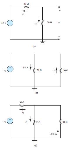
In the circuits of Figure P1.18, the directions of current and polarities of voltage have already been defined. Find the actual values of the indicated currents and voltages.
Solution:
Known quantities: Circuit shown in Figure P1.18.
Find:
Voltages and currents in every figure.
Analysis:
(a) Using I = 15 30+20 (clockwise current) : V A;V A;I I 6 03 03 1 2 1 = = =
(b) The voltage across the 20 resistor is 5V 4 20 = ; since the current flows from top to bottom, the polarity of this voltage is positive on top. Then it follows that V V 5 1 = and -0.167A 30 5 I2 = = (the negative sign follows from the direction of I2 in the drawing).
(c) Since -0.5A pointing upward is the same current as 0.5A pointing downward, the voltage across the 30 resistor is V V 15 30 = (positive on top); and 0.75A 20 15 I2 = = , since 30V is also the voltage across the 20 resistor. Finally,
Copyright 2022 © McGraw Hill LLC. All rights reserved. No reproduction or distribution without the prior written consent of McGraw Hill LLC.
Rizzoni and Kearns, Fundamentals of
Problem 1.19
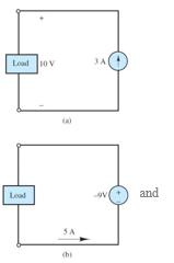
Find the power delivered by each source in Figure P1.19.
Solution:
Known quantities: Circuit shown in Figure P1.19.
a) Power delivered by the 3A Current Source
b) Power delivered by the -9V Voltage Source
Analysis:
a) Follow the counterclockwise current:
supplied
b) Follow the counterclockwise current:
Problem 1.20
=(+5��) ( 9��)
������supplied
Determine whether each element in Figure P2.20 is supplying or dissipating power, and how much.
Solution:
Known quantities: Circuit shown in Figure P1.20.
Find:
Determine power dissipated or supplied for each power source
Analysis:
Element A: W A) V)( -(- -vi P 300 25 12 = = = (dissipating)
Element B: W A) V)( ( vi P 375 25 15 = = = (dissipating)
Element C: W A) V)( ( vi P 675 25 27 = = = (supplying)
Problem 1.21

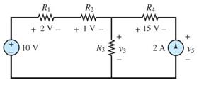
In the circuit of Figure P1.21, find the power absorbed by R4 and the power delivered by the current source.
Copyright 2022 © McGraw Hill LLC. All rights reserved. No reproduction or distribution without the prior written consent of McGraw Hill LLC.
Solution:
Known quantities: Circuit shown in Figure P1.21.
Find:
a) Power absorbed by R4
b) Power delivered by the current source
Analysis:
a) Follow the counterclockwise current in the rightmost loop: �� =(2��) ( 15��)
absorbed ��=+������supplied
b) Use KVL at the leftmost loop to find V3:
Use KVL at the rightmost loop to find V5:
The current source has a -8V drop across it. Use this to calculate the power dissipated using the proper sign convention. (+����) ( ����)= ������supplied
Problem 1.22
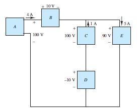
For the circuit shown in Figure P1.22:
a. Determine whether each component is absorbing or delivering power.
b. Is conservation of power satisfied? Explain your answer.
Solution:
Known quantities: Circuit shown in Figure P1.22.
Copyright 2022 © McGraw Hill LLC. All rights reserved. No reproduction or distribution without the prior written consent of McGraw Hill LLC.
Find:
Determine power absorbed or power delivered Testify power conservation
Analysis: By KCL, the current through element B is 5A, to the right. By KVL, 0 5 10 3 = + + av
Therefore, the voltage across element A is v V a = 12 (positive at the top).
A supplies ( )( ) W A V 60 5 12 =
B supplies ( )( ) W A V 15 5 3 =
C absorbs ( )( ) W A V 25 5 5 =
D absorbs ( )( ) W A V 30 3 10 =
E absorbs ( )( ) W A V 20 2 10 =
Total power supplied = W W W 75 15 60 = +
Total power absorbed = W W W W 75 20 30 25 = + + Tot. power supplied = Tot. power absorbed conservation of power is satisfied.
Problem 1.23
For the circuit shown in Figure P1.23, determine the power absorbed by the 5 Ω resistor.
Solution:
Known quantities: Circuit shown in Figure P1.23.
Find:
Power absorbed by the 5 resistance
Analysis:


The current flowing clockwise in the series circuit is A ô V i 1 20 20 = = The voltage across the 5 resistor, positive on the left, is ( )( ) V ô A v ô 5 5 1 5 = =
Therefore, ( )( ) W A V P ô 5 1 5 5 = =
Problem 1.24
For the circuit shown in Figure P1.24, determine which components are supplying power and which are dissipating power. Also determine the amount of power dissipated and supplied.
Copyright 2022 © McGraw Hill LLC. All rights reserved. No reproduction or distribution without the prior written consent of McGraw Hill LLC.
Solution:
Known quantities:
Circuit shown in Figure P1.24.
Find:
Determine power absorbed or power delivered and corresponding amount.
Analysis:
If current direction is out of power source, then power source is supplying, otherwise it is absorbing.
A supplies
100V ( ) 4A ( ) = 400W
B absorbs 10V ( ) 4A ( ) = 40 W
D supplies ( )( ) W A V 10 1 10 = , i.e absorbs W10
E absorbs ( )( ) W A V 450 5 90 =
C supplies 100V ( ) 1A ( ) = 100W
Problem 1.25
For the circuit shown in Figure P1.25.determine which components are supplying power and which are dissipating power. Also determine the amount of power dissipated and supplied.
Solution:
Known quantities:
Circuit shown in Figure P1.25.
Find:
Determine power absorbed or power delivered and corresponding amount.
Analysis:
If current direction is out of power source, then power source is supplying, otherwise it is absorbing.
A absorbs ( )( ) W A V 20 4 5 =
B supplies ( )( ) W A V 12 6 2 =
D supplies ( )( ) W A V 12 4 3 =

Since conservation of power is satisfied, Tot. power supplied = Tot. power absorbed
Total power supplied = 24W 12W 12W = +
Cabsorbs W W W 4 20 24 =
Problem 1.26
If an electric heater requires 23 A at 110 V, determine
a. The power it dissipates as heat or other losses.
b. The energy dissipated by the heater in a 24-hperiod.
Copyright 2022 © McGraw Hill LLC. All rights reserved. No reproduction or distribution without the prior written consent of McGraw Hill LLC.
Rizzoni and Kearns, Fundamentals of
c. The cost of the energy if the power companycharges at the rate 6 cents/kWh.
Solution:
Known quantities:
Current absorbed by the heater; voltage at which the current is supplied; cost of the energy.
Find:
Power consumption
Energy dissipated in 24 hr.
Cost of the Energy
Assumptions:
The heater works for 24 hours continuously.
Analysis:
Sections 1.5-1.6: i-v Characteristics and Sources; Resistance and Ohm’s Law
Problem 1.27
In the circuit shown in Figure P1.27, determine the terminal voltage ���� of the source, the power absorbed by ���� =���� and the efficiency of the circuit. Efficiency is defined as the ratio of load power to source power.
Solution:
Known quantities:

Circuit shown in Figure P1.27 with voltage source, Vs =12V ; internal resistance of the source, Rs = 5k; and resistance of the load, RL = 7k.
Find:
The terminal voltage of the source; the power supplied to the circuit, the efficiency of the circuit.
Assumptions:
Assume that the only loss is due to the internal resistance of the source.
Copyright 2022 © McGraw Hill LLC. All rights reserved. No reproduction or distribution without the prior written consent of McGraw Hill LLC.
Analysis:
Problem 1.28
A 24-V automotive battery is connected to two headlights that are in parallel, similar to that shown in Figure 1.11. Each headlight is intended to be a 75-W load; however, one 100-W headlight is mistakenly installed. What is the resistance of each headlight? What is the total resistance seen by the battery?
Solution:
Known quantities:
Headlights connected in parallel to a 24-V automotive battery; power absorbed by each headlight.
Find:
Resistance of each headlight; total resistance seen by the battery.
Analysis:
Headlight no. 1:
P = v i = 100W = v 2 R or R = v 2
100 = 576 100 = 5 76
Headlight no. 2:
P = v i = 75W = v 2 R or R = v 2
75 = 576 75 = 7 68
The total resistance is given by the parallel combination:
1 RTOTAL = 1 5 76 + 1 7 68 or RTOTAL = 3.29
Copyright 2022 © McGraw Hill LLC. All rights reserved. No reproduction or distribution without the prior written consent of McGraw Hill LLC.
Rizzoni and Kearns, Fundamentals of Electrical Engineering, 2nd Edition
Problem 1.29
What is the equivalent resistance seen by the battery of Problem 1.28 if two 15-W taillights are added (in parallel) to the two 75-W (each) headlights?
Solution:
Known quantities:
Headlights and 24-V automotive battery of problem 2.13 with 2 15-W taillights added in parallel; power absorbed by each headlight; power absorbed by each taillight.
Find:
Equivalent resistance seen by the battery.
Analysis:
The resistance corresponding to a 75-W headlight is:
R75W = v 2 75 = 576 75 = 7.68
For each 15-W tail light we compute the resistance:
R15W = v 2 15 = 576 15 = 38.4
Therefore, the total resistance is computed as:
Problem 1.30
For the circuit shown in Figure P1.30, determine the power absorbed by the variable resistor R, ranging from 0 to 30 . Plot the power absorption as a function of R. Assume that vS = 15 V, RS = 10 .
Solution:
Known quantities:
vs=15V, Rs=10 Ohms, and the circuit in Figure P1.30.
Find: R
Analysis:
Use ohms law to find an equation for P as a function of R:

The voltage across R is equal to the source voltage minus the voltage across Rs:
VRS is determined by the current through the loop which can be found by adding the resistors in series:
Copyright 2022 © McGraw Hill LLC. All rights reserved. No reproduction or distribution without the prior written consent of McGraw Hill LLC.
Rizzoni
Simplify:
Kearns, Fundamentals
Problem 1.31
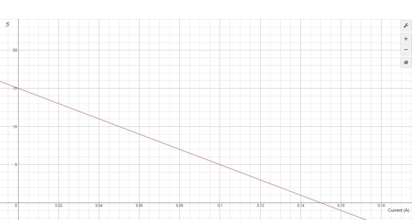
Refer to Figure P1.27 and assume that vS = 15 V and RS = 100 _. For iT = 0, 10, 20, 30, 80, and 100 mA:
a. Find the total power supplied by the ideal source.
b. Find the power dissipated within the non-ideal source.
c. How much power is supplied to the load resistor?
d. Plot the terminal voltage vT and power supplied to the load resistor as a function of terminal current iT
Solution:
Known quantities:
vs=15V, Rs=100 Ohms, iT= 0, 10, 20, 30, 80, 100 mA.
The circuit in Figure P1 27
Find:
a) The total power supplied by the ideal source
b) The power dissipated within the non-ideal source
c) How much power is supplied to the load resistor
d) Plot vT and power supplied to R0 as a function of iT
Analysis:

a) The power supplied by the ideal source is equal to the current through the loop times the 15V of the supply. From current lowest to highest the power supplied would be:
b) The power dissipated within the non-ideal source is the power dissipated by Rs which can be found using P=i2*r. From current lowest to highest the power dissipated would be:
Copyright 2022 © McGraw Hill LLC. All rights reserved. No reproduction or distribution without the prior written consent of McGraw Hill LLC.
Kearns, Fundamentals
c) The power supplied to the load resistor is equal to the total power supplied minus the power dissipated by the non-ideal source. From current lowest to highest the power supplied would be: 0�� 014�� 026�� 036�� 056�� 05��
d) For the vT plot Ohm’s Law can be used to find the voltage drop across Rs which is equal to VT For the power plot, the data from part c can be used directly.

Copyright 2022 © McGraw Hill LLC. All rights reserved. No reproduction or distribution without the prior written consent of McGraw Hill LLC.
Rizzoni and Kearns, Fundamentals of Electrical Engineering, 2nd Edition Problem solutions, Chapter 1
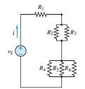
Problem 1.32
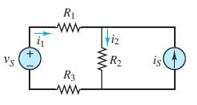
In the circuit in Figure P1.32, assume v2 = vs/6 and the power delivered by the source is 150 mW. Also assume that R1 = 8 k, R2 = 10 k, R3 = 12 k. Find R, vs, v2, and i.
Solution:
Known quantities:
R1=8kΩ, R2=10kΩ, R3=12kΩ and the circuit in Figure P1.32.
Find:
R,vs, v2, and i.
Analysis:
Use ohms law to find vs and i:
Also:
So:

Since we know i, vs can easily be found:
Use Ohm’s law to find Req:
Use Req to find R:
Problem 1.33
A GE SoftWhite Longlife lightbulb is rated as follows:
PR = rated power = 60 W
POR = rated optical power = 820 lumens (lm) (average)
1 lumen = 1/680W
Operating life = 1,500 h (average)
VR = rated operating voltage = 115 V
The resistance of the filament of the bulb, measured with a standard multimeter, is 16.7 Ω Whenthe bulb is connected into a circuit and is operating atthe rated values given above, determine
a. The resistance of the filament.
Copyright 2022 © McGraw Hill LLC. All rights reserved. No reproduction or distribution without the prior written consent of McGraw Hill LLC.
Rizzoni and Kearns, Fundamentals
b. The efficiency of the bulb.
Solution:
Known quantities:
Rated power; rated optical power; operating life; rated operating voltage; open-circuit resistance of the filament.
Find:
The resistance of the filament in operation
The efficiency of the bulb.
Analysis:
Efficiency is defined as the ratio of the useful power dissipated by or supplied by the load to the total power supplied by the source. In this case, the useful power supplied by the load is the optical power. From any handbook containing equivalent units: 680 lumens=1 W
Problem 1.34
An incandescent lightbulb rated at 100 W will dissipate 100 W as heat and light when connected across a 110-V ideal voltage source. If three of these bulbs are connected in series across the same source, determine the power each bulb will dissipate.
Solution:
Known quantities:
Rated power; rated voltage of a light bulb.
Find:
The power dissipated by a series of three light bulbs connected to the nominal voltage.
Assumptions:
The resistance of each bulb doesn’t vary when connected in series.
Analysis:
When connected in series, the voltage of the source will divide equally across the three bulbs. The across each bulb will be 1/3 what it was when the bulbs were connected individually across the source. Power dissipated in a resistance is a function of the voltage squared, so the power dissipated in each bulb when connected in series will be 1/9 what it was when the bulbs were connected individually, or 11.11 W:
Copyright 2022 © McGraw Hill LLC. All rights reserved. No reproduction or distribution without the prior written consent of McGraw Hill LLC.
Ohm’s Law:
Connected in series and assuming the resistance of each bulb remains the same as when connected individually:
Problem 1.35
An incandescent lightbulb rated at 60 W will dissipate 60 W as heat and light when connected across a 100-V ideal voltage source. A 100-W bulb will dissipate 100 W when connected across the same source. If the bulbs are connected in series across the same source, determine the power that either one of the two bulbs will dissipate.
Solution:
Known quantities:
Rated power and rated voltage of the two light bulbs.
Find:
The power dissipated by the series of the two light bulbs.
Assumptions:
The resistance of each bulb doesn’t vary when connected in series.
Analysis:
For the two bulbs in series KVL and KCL require 100V=��100 +��60 and ��100 =��60 The resistance of each bulb when connected individually across a 100V source is
(100��)2
Assume that the resistance of each bulb is the same when operated in series as when operated alone. Then
(167) Plug into the KVL equation to find
The power absorbed by each bulb is
And
Notes: 1. It’s strange but it’s true that a 60 W bulb connected in series with a 100 W bulb will dissipate more power than the 100 W bulb. 2. If the power dissipated by the filament in a bulb decreases, the temperature at which the filament operates and therefore its resistance will decrease. This fact made the assumption about the resistance necessary.
Copyright 2022 © McGraw Hill LLC. All rights reserved. No reproduction or distribution without the prior written consent of McGraw Hill LLC.
Rizzoni and Kearns, Fundamentals
Problem 1.36
Refer to Figure P1.36, and assume that vS = 12 V, R1 = 5 , R2 = 3 , R3 = 4 , and R4 = 5 . Find:
a. The voltage vab.
b. The power dissipated in R2.
Solution:
Known quantities:
Circuit of Figure P2.36. R1=5Ω, R2=3Ω, R3=4Ω, R4=5Ω, vs=12V.
Find:
vab and the power dissipated in R2
Analysis:

Find the current through each resistor pair by combining them in series:
Since there is 12V across both of them Ohm’s law is used to find the currents:
Now find the voltage drop across R1 and R3:
An alternate and more efficient approach is to apply voltage division to find the voltage across R2 and R4, respectively:
It is implied in the calculations that the polarities of v2 and v4 are high (+) to low (-) from above to below each resistor in the figure. Apply KVL to find:
PR2 is equal to Ib times Va:
Copyright 2022 © McGraw Hill LLC. All rights reserved. No reproduction or distribution without the prior written consent of McGraw Hill LLC.
Rizzoni and Kearns, Fundamentals of Electrical Engineering, 2nd Edition Problem solutions, Chapter 1
Problem 1.37
Refer to Figure P1.37, and assume that VS = 7 V, IS = 3A, R1 = 20 , R2 = 12 , and R3 = 10
Find:
a. The currents i1 and i2.
b. The power supplied by the voltage source ����.
Solution:
Known quantities:
Circuit of Figure P2.37. R1=20Ω, R2=12Ω, R3=10Ω, Is=3A, vs=7V.
Find: i1, i2, and Pv.
Analysis:
Use KVL of the rightmost loop:
Use KCL where i1 meets i
Combine the two equations to solve for i
Solve for i2:
Power delivered equals the v
times
Problem 1.38
Refer to Figure P1.38, and assume v1 = 15 V, v2 = 6 V, R1 = 18, R2 = 10. Find:
a. The currents i1 and i2
b. The power delivered by the sources ��1 and ��2

Copyright 2022 © McGraw Hill LLC. All rights reserved. No reproduction or distribution without the prior written consent of McGraw Hill LLC.
Solution:
Known quantities:
Circuit of Figure P2.38. R1=18Ω, R2=10Ω,
Find: i1, i2, Pv1,Pv2
Analysis:
Use KVL of the rightmost loop:
Use KCL where i1 meets is:
The assumption can be made that v1 is equal to the voltage across R
The assumption can be made that the voltage drop across R1 is equal to the difference between v1 and v2
Solve for i:
Power delivered equals the voltage source times the current through it:
Problem 1.39
Consider NiMH hobbyist batteries depicted in Figure P1.39.
a. If V1 = 12.0 V, R1 = 0.15 Ω and Ro = 2.55Ω find the load current Io and the power dissipated by the load.
b. If battery 2 with V2 = 12 V and R2 = 0.28 Ω is placed in parallel with battery 1, will the load current Io increase or decrease? Will the power dissipated by the load increase or decrease? By how much?
Solution:
Known quantities:
Schematic of the circuit in Figure P1.39.
Find:
If
V1 =12.0V,R1 = 0.15,RL = 2.55, the load current and the power dissipated by the load
If a second battery is connected in parallel with battery 1with

V2 =12.0V,R2 = 0.28, determine the variations in the load current and in the power dissipated by the load due to the parallel connection with a second battery.
Copyright 2022 © McGraw Hill LLC. All rights reserved. No reproduction or distribution without the prior written consent of McGraw Hill LLC.
Analysis:
b) with another source in the circuit we must find the new power dissipated by the load. To do so, we write KVL twice using mesh currents to obtain 2 equations in 2 unknowns:
Solving the above equations gives us:
The power dissipated increased by roughly 4%.
Problem 1.40
With no load attached, the voltage at the terminals of a particular power supply is 50.8 V. When a 10-W load is attached, the voltage drops to 49 V.
a. Determine vS and RS for this non-ideal source.
b. What voltage would be measured at the terminals in the presence of a 15-Ω load resistor?
c. How much current could be drawn from this power supply under short-circuit conditions?
Solution:
Known quantities:
Open-circuit voltage at the terminals of the power source is 50.8 V; voltage drop with a 10-W load attached is 49 V.
Find:
The voltage and the internal resistance of the source
The voltage at its terminals with a 15- load resistor attached
The current that can be derived from the source under short-circuit conditions.
Analysis:
(a) ���� =50.8�� is the open-circuit voltage. The power absorbed by the load is
And thus
Apply Ohm’s law to solve for RS
Copyright 2022 © McGraw Hill LLC. All rights reserved. No reproduction or distribution without the prior written consent of McGraw Hill LLC.
Rizzoni and Kearns, Fundamentals
Problem 1.41
A 220-V electric heater has two heating coils that can be switched such that either coil can be used independently or the two can be connected in series or parallel, yielding a total of four possible configurations. If the warmest setting corresponds to 2,000-W power dissipation and the coolest corresponds to 300 W, find
a. The resistance of each of the two coils.
b. The power dissipation for each of the other two possible arrangements.
Solution:
Known quantities:
Voltage of the heater, maximum and minimum power dissipation; number of coils, schematics of the configurations.
Find:
The resistance of each coil
The power dissipation of each of the other two possible arrangements.
Analysis:
(a) For the parallel connection, P = 2000 W. Therefore,
+
or,
1 R1 + 1 R2 = 5 121
For the series connection, P = 300 W. Therefore,
Solving, we find that R1 =1316 and R2 = 297. (b) the power dissipated by R1 alone is:
PR1 = 220( )2 R1 = 368W and the power dissipated by R2 alone is
PR2 = 220( )2 R2 = 1631W
Copyright 2022 © McGraw Hill LLC. All rights reserved. No reproduction or distribution without the prior written consent of McGraw Hill LLC.
Rizzoni and Kearns, Fundamentals of
Section 1.7-1.8: Resistors in Series and Voltage Division; Resistors in Parallel and Current Division
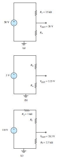
Problem 1.42
For the circuits of Figure P1.42, determine the resistor values (including the power rating) necessary to achieve the indicated voltages. Resistors are available in 1/8-, 1/4-, 1/2-, and 1-W ratings.
Solution:
Known quantities: Circuits of Figure 1.42.
Find:
Values of resistance and power rating
Analysis:
Copyright 2022 © McGraw Hill LLC. All rights reserved. No reproduction or distribution without the prior written consent of McGraw Hill LLC.
Problem 1.43
At an engineering site, a 1-hp motor is placed a distance d from a portable generator, as depicted in Figure P1.43. The generator can be modeled as an ideal DC source VG = 110 V. The nameplate on the motor gives the following rated voltages and full-load currents:
VMmin = 105 V → IMFL = 7.10 A
VMmax = 117 V → IMFL = 6.37 A
If d = 150m and the motor must deliver its full-rated power, determine the minimum AWG conductors that must be used in a rubber-insulated cable. Assume that losses occur only in the wires.

Solution:
Known quantities: Figure P1.43.
Find:
The minimum AWG wire that will meet the specifications.
Assumptions:
Assume an ideal DC source.
Analysis:
The circuit that this setup is describing is essentially a voltage source with a resistor, an inductor, and another resistor all in series.
350m is equal to 1148.29 feet. This will help with the resistance later.
Assume the voltage of the motor is 105V. Use Ohm’s Law to calculate the Current through the first conductor: ���� = 110�� 105�� 2��
IM has to be 7.1 A or greater in order for the motor to draw full power: 7.1��= 25�� �� �� =0352��
Use the value of R along with the chart to find the correct AWG: 0.352�� 1.14829=0.307��@1000����
Copyright 2022 © McGraw Hill LLC. All rights reserved. No reproduction or distribution without the prior written consent of McGraw Hill LLC.
Rizzoni and Kearns, Fundamentals
This means that 4 AWG wire must be used.
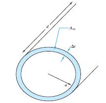
Problem 1.44
Cheap resistors are fabricated by depositing a thin layer of carbon onto a nonconducting cylindrical substrate (see Figure P1.44). If such a cylinder has radius a and length d, determine the thickness of the film required for a resistance R if a = 1 mm R = 33 kΩ σ = 1/ρ= 2.9 MS/m d = 9 mm
Neglect the end surfaces of the cylinder and assume that the thickness is much smaller than the radius.
Solution:
Known quantities: Figure P1.50. Diameter of the cylindrical substrate; length of the substrate; conductivity of the carbon.
Find:
The thickness of the carbon film required for a resistance R of 33 k.
Assumptions:
Assume the thickness of the film to be much smaller than the radius
Neglect the end surface of the cylinder.
Analysis:
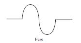
Problem 1.45
The resistive elements of fuses, lightbulbs, heaters, etc., are nonlinear (i.e., the resistance is dependent on the current through the element). Assume the resistance of a fuse (Figure P1.45) is given by R = R0[1 + A(T −T0)] with: T −T0 = kP; T0 = 25◦C; A = 0 7[◦C]−1; k = 0 35◦C/W; R0 = 0 11 Ω; and P is the power dissipated in the resistive element of the fuse. Determine the rated current at which the circuit will melt (that is, “blow”) and thus act as an open-circuit. (Hint: The fuse blows when R becomes infinite.)
Solution:
Known quantities:
Figure P1.45 The constants A and k; the open-circuit resistance.
Find:
The rated current at which the fuse blows, showing that this happens at:
Copyright 2022 © McGraw Hill LLC. All rights reserved. No reproduction or distribution without the prior written consent of McGraw Hill LLC.
Rizzoni and Kearns, Fundamentals of
I = 1
AkR0
Assumptions:
Here the resistance of the fuse is given by:
R = R0 1+ A(T T0) where T0, room temperature, is assumed to be 25°C. We assume that:
T T0 = kP where P is the power dissipated by the resistor (fuse).
Analysis:
R = R0(1+ A T ) = R0(1+ AkP) = R0(1+ AkI 2R)
R R0AkI 2R = R0 R = R0 1 R0AkI2 → when I R0AkI 2 → 0
Problem 1.46
Use KCL and Ohm’s law to determine the current in each of the resistors R4, R5, and R6 in the circuit of Figure P1 46 VS = 10 V, R1 = 20 Ω, R2 = 40 Ω, R3 = 10 Ω, R4 = R5 = R6 = 15 Ω.
Solution:
Known quantities:
Find:
The current in the 15- resistors.
Circuit shown in Figure P1.46 with voltage source, Vs =10V and resistors, R1 = 20,R2 = 40,R3 =10,R4 = R5 = R6 =15
Analysis:
Since the 3 resistors must have equal currents, and, I = VS R1 + R2 || R3 + R4 || R5 || R6 = 10 20+ 8 + 5 = 10 33 = 303 mA
Therefore, I15 = 10 99 = 101 mA I 3 1 I15 =
Copyright 2022 © McGraw Hill LLC. All rights reserved. No reproduction or distribution without the prior written consent of McGraw Hill LLC.
Rizzoni and Kearns, Fundamentals of Electrical Engineering, 2nd Edition Problem solutions, Chapter 1
Problem 1.47
Refer to Figure P1.13. Assume R0 = 1 Ω, R1 = 2 Ω, R2 = 3 Ω, R3 = 4 Ω, and vS = 10 V. Use KCL and Ohm’s law to find the unknown currents.

Solution:
Known quantities:
Circuit shown in Figure P1.13 R0=1, R1=2, R2=3, R3=4, vs=10V
Find: a) i0 b) i1 c) i2 d) i3
Analysis:
Use KVL at mesh A:
10=(��0 1)+(��1 2) Eq. 1
Use KVL at middle + right mesh: (��1 ∙��1)= (��2 ∙��2) (��3 ∙��3) Eq. 2
Use KCL at node A:
��1 =��0 +��2 Eq. 3
Use KCL at node B:
��2 =��3 6�� Eq. 4
Use algebra to solve the four equations with four unknowns:
Copyright 2022 © McGraw Hill LLC. All rights reserved. No reproduction or distribution without the prior written consent of McGraw Hill LLC.
Rizzoni and Kearns, Fundamentals of Electrical Engineering, 2nd Edition Problem solutions, Chapter 1
Problem 1.48
Use KCL and Ohm’s law to find the power delivered by the voltage source in Figure P1.48. Assume k=0.25A/A2 .
Solution:
Known quantities:
Circuit shown in Figure P1.48
k=0.25A/A2
Find:
Power supplied by the voltage source.
Analysis:

The 7 Ohm and 5 Ohm resistor are in series so i can be found by using Ohm’s law: 24�� =12∗��
The dependent current source current can therefore be found using i:
=0.25∗(2��)2
Use KCL to determine the current through the voltage source:
Use P=v*I to determine the power supplied by the voltage source:
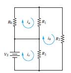
Problem 1.49
Assuming R0 = 2 Ω, R1 = 1Ω, R2 = 4/3 Ω R3 = 6 Ωand VS = 12 V in the circuit of Figure P1 49, use Kirchhoff’s voltage law and Ohm’s law to find ia, ib, and ic.
Solution:
Known quantities:
Schematic of the circuit shown in Figure P1.49 with resistors
R0 = 2,R1 =1,R2 = 4/3,R3 = 6 and voltage source
VS =12V.
Find:
The current through each resistor.
Analysis:
The mesh currents ia , ib , ic
Applying KVL to mesh (a), mesh (b) and mesh (c):
Copyright 2022 © McGraw Hill LLC. All rights reserved. No reproduction or distribution without the prior written consent of McGraw Hill LLC.
Solving the system we obtain:
ia = 2 A
ib = 6 A
ic = 8 A
IR 0 = ia = 2 A (positive in the direction of ia )
IR1 = ib ia = 4 A (positive in the direction ofib ) IR 2 = ib = 6 A (positive in the direction of ib )
IR 3 = ic ib = 2 A (positive in the direction ofic )
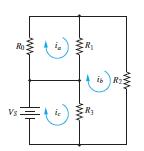
Problem 1.50
Refer to Figure P1.49 and assume R0 = 2Ω, R1 = 2 Ω, R2 = 5 Ω, R3 = 4 A, and VS = 24 V. Use KCL and Ohm’s law to find:
a. ia, ib, and ic b. The voltage across each resistor.
Solution:
Known quantities:
Schematic of the circuit shown in Figure P1.49 with resistors
R0 = 2,R1 = 2,R2 = 5,R3 = 4 and voltage source
Find:
The mesh currents
ib ,
ic The current through each resistor.
Analysis:
Applying KVL to mesh (a), mesh (b) and mesh (c):
iaR0 + ia ib ( )R1 = 0 ia ib ( )R1 ibR2 + ic ib ( )R3 = 0 VS = ic ib ( )R3
Solving the system we obtain:
ia = 2 A ib = 4 A ic = 10 A
ia + 2 ia ib ( )= 0 2 ia ib ( ) 5ib + 4 ic ib ( )= 0
ic ib ( )= 24
VR 0 = R0ia = 4 V ( up) VR1 = R1 ib ia ( ) = 4 V ( down)
VR 2 = R2ib = 20 V ( up)
VR 3 = R3 ic ib ( ) = 24 V ( up)
Copyright 2022 © McGraw Hill LLC. All rights reserved. No reproduction or distribution without the prior written consent of McGraw Hill LLC.
Rizzoni and Kearns, Fundamentals
Problem 1.51
Assume that the voltage source in the circuit of Figure P1.49 is now replaced by a current source IS, and R0 = 1 Ω, R1 = 3 Ω, R2= 2Ω, R3 = 4 Ω, and IS = 12 A, directed positively upward. Use KVL and Ohm’s law to determine the voltage across each resistor.
Solution:
Known quantities:
Find:
The voltage across each resistance.
Schematic of the circuit shown in Figure P1.49 with resistors R0 =1,R1 = 3,R2 = 2,R3 = 4 and of the current source IS =12A.
Analysis:
Applying KVL to mesh (a), mesh (b) and mesh (c):
Solving the system we obtain:
ia = 16 3 A ib = 64 9 A ic = 12 A
R 0 = R0ia = 5.33 V ( up) VR1 = R1 ib ia ( ) = 5.33 V ( down) VR 2 = R2ib = 14 22 V ( up)
Problem 1.52
The voltage divider network of Figure P1.52 is expected to provide �������� =����/2 However, in practice, the resistors may not be perfectly matched; that is, their tolerances are such that the resistances are unlikely to be identical. Assume vS = 10 V and nominal resistance values of R1 = R2 = 5 kΩ.
a. If the resistors have +/-10 percent tolerance, find the expected range of possible output voltages.
b. Find the expected output voltage range for a tolerance of +/-5 percent.
Solution:
Known quantities:
Schematic of voltage divider network shown of Figure P1.52
Find:
Analysis:
The worst-case output voltages for 10percent tolerance The worst-case output voltages for 5percent tolerance
a) 10% worst case: low voltage R2 = 4500 , R1 = 5500

Copyright 2022 © McGraw Hill LLC. All rights reserved. No reproduction or distribution without the prior written consent of McGraw Hill LLC.
vOUT,MIN = 4500 4500+ 5500 5 = 2 25V
10% worst case: high voltage
R2 = 5500 , R1 = 4500
vOUT,MAX = 5500 4500+ 5500 5 = 2.75V
b) 5% worst case: low voltage
R2 = 4750 , R1 = 5250
vOUT,MIN = 4750 4750+ 5250 5 = 2.375V
5% worst case: high voltage
R2 = 5250 , R1 = 4750
vOUT,MAX = 5250 5250+ 4750 5 = 2 625V
Sections 1.9-1.10: Practical Voltage and Current Sources; Measurement Devices
Problem 1.53
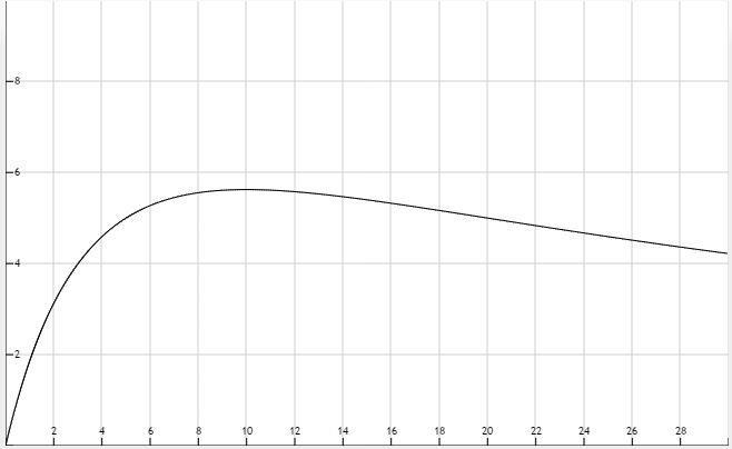
A thermistor is a nonlinear device that changes its terminal resistance value as its surrounding temperature changes. The resistance and temperature generally have a relation in the form of Rth(T ) = R0e β(T−To), where Rth = resistance at temperature T, (Ω), R0 = resistance at temperature T0 = 298 K, (Ω), β = material constant, (K 1), T, T0 = absolute temperature, (K).
a. If R0 = 300Ω and β = −0.01 K 1, plot Rth as a function of the surrounding temperature T for 350 ≤ T ≤ 750.
b. If the thermistor is in parallel with a 250-Ω resistor, find the expression for the equivalent resistance and plot Rth(T ) on the same graph for part a.
Solution:
Known quantities:
Find:
Parameters 0 300 R = (resistance at temperature 0T = 298 K), and = 0 01 K-1, value of the second resistor.
a) Plot Rth(T) versus T in the range 350 T 750[K]
b) The equivalent resistance of the parallel connection with the 250- resistor; plot Req (T ) versus T in the range 350 T 750[K] for this case on the same plot as part a.
Copyright 2022 © McGraw Hill LLC. All rights reserved. No reproduction or distribution without the prior written consent of McGraw Hill LLC.
Rizzoni and Kearns, Fundamentals
Assumptions:
Analysis:
The two plots are shown below.
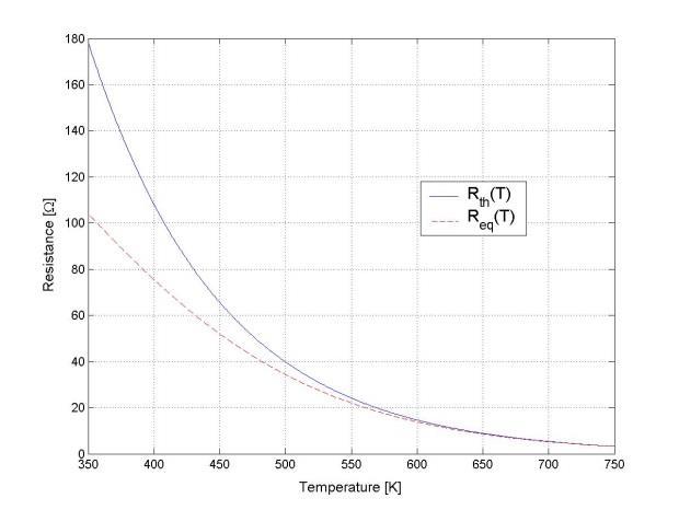
In the above plot, the solid line is for the thermistor alone; the dashed line is for the thermistor-resistor combination.
Problem 1.54
A moving-coil meter movement has a meter resistance rM= 200 Ω, and full-scale deflection is caused by a meter current Im= 10 μA. The meter is to be used to display pressure, as measured by a sensor, up to a maximum of 100 kPa. Models of the meter and pressure sensor are shown in Figure P1.54 along with the relationship between measured pressure and the sensor output vT
a. Devise a circuit that will produce the desired behavior of the meter, showing all appropriate connections between the terminals of the sensor and the meter.
b. Determine the value of each component in the circuit.
c. What is the linear range, that is, the minimum and maximum pressure that can accurately be measured?

Copyright 2022 © McGraw Hill LLC. All rights reserved. No reproduction or distribution without the prior written consent of McGraw Hill LLC.
Solution:
Known quantities:
Meter resistance of the coil; meter current for full scale deflection; max measurable pressure.
Find:
a) The circuit required to indicate the pressure measured by a sensor
b) The value of each component of the circuit; the linear range
c) The maximum pressure that can accurately be measured.
Assumptions:
Sensor characteristics follow what is shown in Figure P2.78
Analysis:
a) A full-scale deflection should occur at a pressure of 100kPa. Thus, at this pressure, the meter current should be 10����. Since the meter coil resistance is 200 the voltage across the coil should be (10����)(200Ω)=2����.
Assume that the sensor data was measured under open-circuit conditions such that ���� = ���� =10���� at 100kPa. Therefore, when the sensor and meter are connected the voltage across and current through ���� should be 8���� and 10����, respectively.
b) Consequently:
c) By observation, ���� ∝���� so the deflection of the meter will be linear with pressure as long as ���� is linear with pressure. From the graph of ���� versus pressure that range appears to be roughly 25kPa to 100kPa.
Problem 1.55
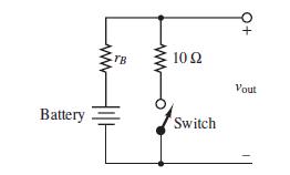
The circuit of Figure P1.55 is used to measure the internal resistance rB of a battery.
a. A fresh battery is being tested, and it is found that the voltage Vout , is 2.28 V with the switch open and 2.27 V with the switch closed. Apply voltage division to find the internal resistance of the battery.
b. The same battery is tested one year later, and Vout is found to be 2.2 V with the switch open but 0.31 V with the switch closed. Apply voltage division to find the internal resistance of the battery.
Solution:
Known quantities:
Schematic of the circuit shown in Figure P1.55; voltage at terminals with switch open and closed for fresh battery; same voltages for the same battery after 1 year.
Copyright 2022 © McGraw Hill LLC. All rights reserved. No reproduction or distribution without the prior written consent of McGraw Hill LLC.
Rizzoni
Find:
Kearns,
The internal resistance of the battery in each case.
Analysis:
a) With the switch open ���� =������ =�������� =228�� is the open-circuit voltage. Apply voltage division to find the internal resistance.
b) Apply voltage division again using the data from 1 year later.
Problem 1.56
Consider the practical ammeter, depicted in Figure P1.56, consisting of an ideal ammeter in series with a 1kΩ resistor. (An ideal ammeter acts like a short-circuit.) The meter sees a fullscale deflection when the current through it is 30 μA. Depending upon the setting of the rotary switch, the ammeter will read full-scale when the current I equals 10mA, 100mA and 1A. Apply current division to determine the appropriate values of R1, R2, and R3.
Solution:
Known quantities:
Ammeter shown in Figure P1.56; Current for full-scale deflection; desired full scale values.
Find:
Value of the resistors required for the given full scale ranges.
Analysis:

Apply current division:
Solve
Copyright 2022 © McGraw Hill LLC. All rights reserved. No reproduction or distribution without the prior written consent of McGraw Hill LLC.
Rizzoni
Kearns, Fundamentals
Problem 1.57
A circuit that measures the internal resistance of a practical ammeter is shown in Figure P1.57, where RS = 50,000 Ω, vS = 12 V, and Rp is a variable resistor that can be adjusted at will.
a. Assume that ra << 50,000 Ω. Estimate the current i.
b. If the meter displays a current of 150 μA when Rp = 15 Ω, find the internal resistance of the meter ra.

Solution:
Known quantities:
Schematic of the circuit shown in Figure P1.57; for part b: value of R p and current displayed on the ammeter.
Find:
The current i; the internal resistance of the meter.
Assumptions:
ra 50 k
Analysis:
a) Assuming that i = 240 A
b) With the same assumption as in part a)
Copyright 2022 © McGraw Hill LLC. All rights reserved. No reproduction or distribution without the prior written consent of McGraw Hill LLC.
meteri = 150 (10)-6 = Rp ra +Rp i or:
150(10)-6= 15 r a +15 (240×10-6 )
Therefore, a r = 9 .
Problem 1.58
A practical voltmeter has an internal resistance rm. What is the value of rm if the meter reads 11.81V when connected as shown in Figure P1.58?

Solution:
Known quantities:
Voltage read at the meter; schematic of the circuit shown in Figure P1.58 with source voltage, and source resistance,
Find: The internal resistance of the voltmeter.
Analysis:
Apply voltage division to find: V = 11.81 =
Therefore, m r = 1.55 M
Copyright 2022 © McGraw Hill LLC. All rights reserved. No reproduction or distribution without the prior written consent of McGraw Hill LLC.
Rizzoni and Kearns, Fundamentals of Electrical Engineering, 2nd Edition Problem solutions, Chapter 1
Problem 1.59
Using the circuit of Figure P1.58, find the voltage that the meter reads if VS = 24 V and RS has the following values: RS = 0.2
, and 10rm. How large (or small) should the internal resistance of the meter be relative to RS?
Solution:
Known quantities:
Circuit shown in Figure P1.58 with source voltage, V s = 24V ; and ratios between and m r .
Find:
The meter reads in the various cases.
Analysis: By voltage division:
For a voltmeter, it is desired that m r >> s R s R
Copyright 2022 © McGraw Hill LLC. All rights reserved. No reproduction or distribution without the prior written consent of McGraw Hill LLC.
Rizzoni and Kearns, Fundamentals of
Problem 1.60
A voltmeter is used to determine the voltage across a resistive element in the circuit of Figure P1.60. The instrument is modeled by an ideal voltmeter in parallel with a 120kΩ resistor, as shown. The meter is placed to measure the voltage across R4. Assume R1 = 8 kΩ, R2 = 22 kΩ, R3 = 50 kΩ, RS = 125 kΩ, and IS = 120 mA. Find the voltage across R4 with and without the voltmeter in the circuit for the following values:
a. R4 = 100 Ω
b. R4 = 1 kΩ
c. R4 = 10 kΩ
d. R4 = 100 kΩ
Solution:
Known quantities:
Schematic of the circuit shown in Figure P1.60, values of the components.
Find:
a)
b)

R4 =100
R4 =1k c)
The voltage across R4 with and without the voltmeter for the following values:
R4 =10k d)
R4 =100k .
Assumptions:
The voltmeter behavior is modeled as that of an ideal voltmeter in parallel with a 120- k resistor.
Analysis:
We develop first an expression for
Copyright 2022 © McGraw Hill LLC. All rights reserved. No reproduction or distribution without the prior written consent of McGraw Hill LLC.
Without the voltmeter: a)
VR4 = 269.9 V d)
VR4 = 1260 V
To find the voltage drop across R4 with a 120-k resistor across R4 simply replace R4 above with R4||120K.
Problem 1.61
An ammeter is used as shown in Figure P1.61. The ammeter model consists of an ideal ammeter in series with a resistance. The ammeter model is placed in the branch as shown in the figure. Find the current through R5 both with and without the ammeter in the circuit for the following values, assuming that RS = 20 Ω, R1 =800 Ω, R2 = 600 Ω, R3 = 1.2 kΩ, R4 = 150 Ω, and VS = 24 V.
a. R5 = 1 kΩ
b. R5 = 100 Ω
c. R5 = 10 Ω
d. R5 = 1 Ω
Solution:
Known quantities:
Schematic of the circuit shown in Figure P1.61 and the values of the components.
Find:
R5 =1k b)
R5 =100

The current through R5 with and without the ammeter, for the following values of R5: a)
c)
R5 =10
Copyright 2022 © McGraw Hill LLC. All rights reserved. No reproduction or distribution without the prior written consent of McGraw Hill LLC.
Analysis:
First, find the Norton equivalent of the network to the left of R3, including R3 The Norton equivalent resistance is
Replace the branch containing the ammeter with a short-circuit (a wire) and solve for that shortcircuit current. R3 plays no part in the calculation since it is in parallel with the short-circuit and with the short-circuit in place R1 and R2 are in parallel. Apply voltage division to find the voltage across R1||R2.
The short-circuit current is the current through R2 so
Attach the ammeter branch to the Norton equivalent network and apply current division to find the current through the ammeter.
The current through that branch without the ammeter in place is
Use the above equations fill in the following table:
Problem 1.62
Figure P1.62 shows an aluminum cantilevered beam loaded by the force F. Strain gauges R1, R2, R3, and R4 are attached to the beam as shown in Figure P1.62 and connected into the circuit shown. The force causes a tension stress on the top of the beam that causes the length (and therefore the resistance) of R1 and R4 to increase and a compression stress on the bottom of the beam that causes the length (and therefore the resistance) of R2 and R3 to decrease. The result is a voltage of 50 mV at node B with respect to node A Determine the force if Ro = 1 kΩ, VS = 12 V, L = 0 3 m, w = 25 mm, h = 100 mm, and Y = 69 GN/m2

Copyright 2022 © McGraw Hill LLC. All rights reserved. No reproduction or distribution without the prior written consent of McGraw Hill LLC.
Rizzoni and Kearns, Fundamentals of
Solution:
Known quantities:
Schematic of the circuit and geometry of the beam shown in Figure P1.62, characteristics of the material, reads on the bridge.
Find:
The force applied on the beam.
Assumptions:
Gage Factor for strain gauge is 2.
Analysis: R 1 and R 2 are in series; R 3 and R 4 are in series.
LF
assuming GF=2 for aluminum.
Copyright 2022 © McGraw Hill LLC. All rights reserved. No reproduction or distribution without the prior written consent of McGraw Hill LLC.
Rizzoni and Kearns, Fundamentals of
Problem 1.63
Refer to Figure P1.62 but assume that the cantilevered beam loaded by a force F is made of steel. Strain gauges R1, R2, R3, and R4 are attached to the beam and connected in the circuit shown. The force causes a tension stress on the top of the beam that causes the length (and therefore the resistance) of R1 and R4 to increase and a compression stress on the bottom of the beam that causes the length (and therefore the resistance) of R2 and R3 to decrease. The result is a voltage ������ across nodes B and A. Determine this voltage if F = 1.3 MN, Ro = 1 kΩ, VS = 24 V L = 1.7 m, w = 3 cm, h = 7 cm, Y = 200 GN/m2
Solution:
Known quantities:
Schematic of the circuit and geometry of the beam shown in Figure P1.62, characteristics of the material, reads on the bridge.
Find:
The force applied on the beam.
Assumptions:
Gage Factor for strain gauge is 2.
Analysis: R 1 and R 2 are in series; R 3 and R 4 are in series.
Assuming GF=2 for aluminum.
Copyright 2022 © McGraw Hill LLC. All rights reserved. No reproduction or distribution without the prior written consent of McGraw Hill LLC.