Electronics Principles and Applications
Ninth Edition
Charles A.Schuler
Published by McGraw-Hill Higher Education, an imprint of The McGraw-Hill Companies, Inc., 1221 Avenue of the Americas, New York, NY 10020. Copyright © 2019, 2013, 2008 by The McGraw-Hill Companies, Inc. All rights reserved. The contents, or parts thereof, may be reproduced in print form solely for classroom use with Electronics: Principles and Applications, provided such reproductions bear copyright notice, but may not be reproduced in any other form or for any other purpose without the prior written consent of The McGraw-Hill Companies, Inc., including, but not limited to, in any network or other electronic storage or transmission, or broadcast for distance learning.
Preface iv
Part 1 Instructor Resources
Section 1 Parts and Equipment List 2
Section 2 Learning Objectives 5
Section 3 Answers to Student Textbook Questions 9
A. Chapter Review Questions and Problems 9
B. Suggested Answers to Critical Thinking Questions 14
Section 4 Answers to Experiments Manual 21
Part 2 Ancillary Material
Section 1 Projects P-1
Section 2 Instrumentation I-1
Preface
The Instructor Manual for Electronics: Principles and Applications, ninth edition, is designed to save you time. Part 1 contains materials related to the student textbook and Experiments Manual. In Section 1, you will find a listing of the off-the-shelf components needed to perform all the lab experiments and most of the design and troubleshooting problems in the Experiments Manual. Section 2 contains a chapter-by-chapter listing of specific learning objectives for the textbook and the Experiments Manual. Section 3 provides answers to the Chapter Review Questions and Problems, as well as the Critical Thinking Questions, found at the end of each chapter in the student textbook. Section 4 supplies the answers to the Experiments Manual exercises. It contains waveforms, graphs, completed tables, and answers to the questions that follow each experiment.
Circuit files for the simulation experiments are on the Online Learning Center. Open the appropriate chapter folder and look for the figure number of interest.
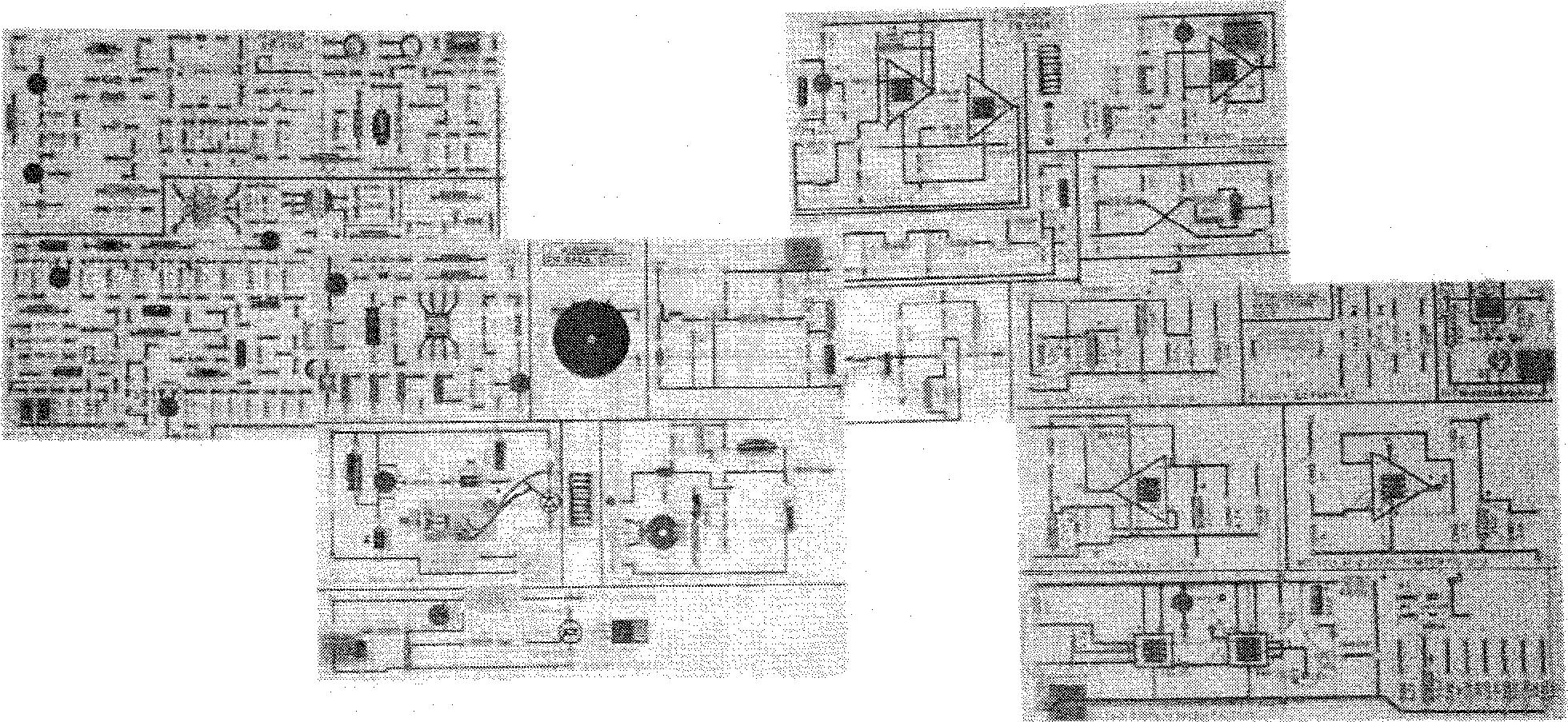
One of the most time-consuming tasks in wiring many of the experiments in the Experiments Manual is to mount and wire the many components. An alternative to loose components is the ETS-900A Electronics Activities System shown on the next page. The ETS-900A consists of four experiment circuit boards: EB-914A, EB-915A, EB-916A, and EB-919. The components are soldered to the boards and divided into circuit areas that are directly correlated to the experiments in the manual. For more information about these products, contact:
Dynalogic Concepts, Inc.
10200 Wales Loop Bonita Springs, Florida 34135
1-800-246-4907
239-949-1326
With the Dynalogic system, students learn to build a circuit from a schematic diagram. Components are connected by using No. 22 AWG solid wire that plugs into miniature spring sockets; this helps students learn basic breadboarding techniques. As students progress through the experiments, the circuits are prewired, allowing more time to study the circuits.
The results of each experiment and problem in the Experiments Manual have been thoroughly tested and verified. I would be interested in hearing about your experiences with these materials.
Part 2 contains ancillary materials. Section 1 contains parts lists and descriptions for construction projects. These projects are suggestions for circuits relevant to the learning of analog electronics.
www.dynalogicconcepts.com
Section 2 of Part 2 contains instrumentation masters for simulated experiments covering key concepts in basic instrumentation. The software files necessary for these experiments are available on the Instructor Side of the Online Learning Center. They are Multisim files for learning the concepts of electronic instrumentation. Again, feel free to copy this material for distribution to your students.
The Online Learning Center contains instructional PowerPoint presentations for each chapter; a Test Bank with questions for each chapter; presentations on breadboarding, soldering, and circuit interrupters; plus many Multisim circuit files. I hope that you find these additional teaching aids helpful.
Charles A. Schuler
SECTION 2
Learning Objectives
FINAL OBJECTIVES
Upon successful completion of the text and Experiments Manual, the student will be able to:
1. Work safely with basic tools, test equipment, and circuitry.
2. Use schematic diagrams to construct basic electronic circuits.
3. Use block diagrams to coordinate electronic system analysis.
4. Use common electronic test equipment to verify and document electronic circuit operation.
5. Troubleshoot basic electronic circuits at both the system level and the component level.
6. Use data sheets, catalogs, substitution guides, and other reference materials to properly choose replacement parts.
7. Analyze and troubleshoot both nonregulated and regulated power supplies, small- and large-signal amplifiers, differential amplifiers, operational amplifiers, oscillators, simple radio circuitry, circuits utilizing ICs, basic electronic control circuits, and DSP systems.
8. Use computer simulations for electronic circuits.
CHAPTER OBJECTIVES
CHAPTER 1 INTRODUCTION
1-1. Identify some major events in the history of electronics.
1-2. Classify circuit operation as digital or analog.
1-3. Name major analog circuit functions.
1-4. Begin developing a system viewpoint for troubleshooting.
1-5. Analyze circuits with both dc and ac sources.
1-6. List the current trends in electronics.
CHAPTER 2 SEMICONDUCTORS
2-1. Identify some common electronic materials as conductors or semiconductors.
2-2. Predict the effect of temperature on conductors.
2-3. Predict the effect of temperature on semiconductors.
2-4. Show the directions of electron and hole currents in semiconductors.
2-5. Identify the majority and minority carriers in N-type semiconductors.
2-6. Identify the majority and minority carriers in P-type semiconductors.
2-7. Explain the term band gap.
CHAPTER 3 DIODES
3-1. Predict the conductivity of diodes under the conditions of forward and reverse bias.
3-2. Interpret volt-ampere characteristic curves for diodes.
3-3. Identify the cathode and anode leads of some diodes by visual inspection.
3-4. Identify the cathode and anode leads of diodes by ohmmeter testing.
3-5. Identify diode schematic symbols.
3-6. List several diode types and applications.
3-7. Describe the structure and characteristics of photovoltaic devices.
CHAPTER 4 POWER SUPPLIES
4-1. View power supplies as systems.
4-2. Identify and explain common rectifier circuits.
4-3. Predict and measure dc output voltage for unfiltered and filtered power supplies.
4-4. Explain how voltage multipliers work.
4-5. Measure and calculate ripple and voltage regulation.
4-6. Explain and make basic calculations for zener voltage regulators.
4-7. Troubleshoot power supplies.
4-8. Select replacement parts.
CHAPTER 5 TRANSISTORS
5-1. Define amplification and power gain.
5-2. Identify transistor schematic symbols and leads.
5-3. Calculate current gain.
5-4. Identify power-supply polarity and current flow for NPN and PNP transistors.
5-5. Interpret characteristic curves and determine current gain and power dissipation.
5-6. Discuss package styles and data sheets.
5-7. Test bipolar junction transistors using an ohmmeter.
5-8. Explain junction field-effect transistors and metal oxide semiconductor field-effect transistors and identify their schematic symbols.
5-9. Compare the types of transistors.
5-10. Explain how power transistors differ from small signal transistors.
5-11. Discuss power packages and the need for heat transfer.
5-12. Explain transistor switching and hard saturation.
5-13. Explain analog switching.
CHAPTER 6 INTRODUCTION TO SMALL-SIGNAL AMPLIFIERS
6-1. Calculate decibel gain and loss.
6-2. Draw a load line for a basic common-emitter amplifier.
6-3. Define clipping in a linear amplifier.
6-4. Find the operating point for a basic common-emitter amplifier.
6-5. Determine common-emitter amplifier voltage gain.
6-6. Identify common-base and common-collector amplifiers.
6-7. Explain the importance of impedance matching.
6-8. Discuss SPICE and explain the importance of models.
6-9. Define THD (total harmonic distortion).
CHAPTER 7 MORE ABOUT SMALL-SIGNAL AMPLIFIERS
7-1. Identify the standard methods of signal coupling and list their characteristics.
7-2. Calculate the input impedance of common-emitter amplifiers.
7-3. Find voltage gain in cascade amplifiers.
7-4. Draw a signal load line for a common-emitter amplifier.
7-5. Solve FET amplifier circuits.
7-6. Identify negative feedback and list its effects.
7-7. Determine the frequency response of a common-emitter amplifier.
7-8. Identify positive feedback and list its effects.
7-9. Define hysteresis.
CHAPTER 8 LARGE-SIGNAL AMPLIFIERS
8-1. Calculate amplifier efficiency.
8-2. Identify the class of amplifier operation.
8-3. Recognize crossover distortion in push-pull amplifiers.
8-4. Explain the operation of complementary symmetry amplifiers.
8-5. Describe tank circuit action in class C amplifiers.
8-6. Explain how class D amplifiers work.
CHAPTER 9 OPERATIONAL AMPLIFIERS
9-1. Predict the phase relationships in differential amplifiers.
9-2. Determine the CMRR for differential amplifiers.
9-3. Calculate the power bandwidth for operational amplifiers.
9-4. Find voltage gain for operational amplifiers.
9-5. Determine the small-signal bandwidth for operational amplifiers.
9-6. Identify various applications for operational amplifiers.
9-7. Discuss the operation and application of comparators.
CHAPTER 10 TROUBLESHOOTING
10-1. Save troubleshooting time by performing preliminary checks.
10-2. Develop and use a system view.
10-3. Use procedures that prevent electrostatic discharge.
10-4. Troubleshoot for the symptom of no output.
10-5. Troubleshoot for reduced output.
10-6. Correct distortion and noise problems.
10-7. Deal with intermittent problems.
10-8. Troubleshoot op-amp circuits.
10-9. Explain how boundary scan can be used to troubleshoot circuits.
10-10. Explain how thermal issues relate to the troubleshooting process.
CHAPTER 11 OSCILLATORS
11-1. Identify oscillator circuits.
11-2. Apply the concepts of gain and feedback to oscillators.
11-3. Predict the frequency of operation for oscillators.
11-4. List causes of undesired oscillations.
11-5. Discuss how op-amp loading can cause instability and ringing.
11-6. Identify techniques used to prevent undesired oscillation.
11-7. Troubleshoot oscillators.
11-8. Explain and troubleshoot direct digital synthesizers.
CHAPTER 12 COMMUNICATIONS
12-1. Define modulation and demodulation.
12-2. List the characteristics of AM, SSB, and FM.
12-3. Explain the operation of basic radio receivers.
12-4. Predict the bandwidth of AM signals.
12-5. Calculate the oscillator frequency for superheterodyne receivers.
12-6. Calculate the image frequency for superheterodyne receivers.
12-7. List some methods of digital modulation and discuss where they are used.
12-8. Describe wireless data systems.
12-9. Troubleshoot receivers.
12-10. Troubleshoot wireless data systems.
CHAPTER 13 INTEGRATED CIRCUITS
13-1. Compare integrated circuit (IC) technology with discrete technology.
13-2. Explain the photolithographic process used to make ICs.
13-3. Make calculations for 555 timer circuits.
13-4. Identify analog, digital, and mixed signal ICs.
13-5. Troubleshoot circuits with ICs.
CHAPTER 14 ELECTRONIC CONTROL DEVICES AND CIRCUITS
14-1. Calculate efficiency in control circuits.
14-2. Identify the schematic symbols for thyristors.
14-3. Explain the operation of thyristors.
14-4. Define conduction angle in thyristor circuits.
14-5. Explain commutation in thyristor circuits.
14-6. Discuss servomechanisms.
14-7. Explain the operation of photovoltaic and LED controllers.
14-8. Troubleshoot control circuits.
CHAPTER 15 REGULATED POWER SUPPLIES
15-1. Perform basic calculations for power-supply regulator circuits.
15-2. Explain the use of feedback in voltage regulator circuits.
15-3. Identify the types of current regulation.
15-4. Identify crowbar circuits.
15-5. Identify switch-mode regulators and their characteristics.
15-6. Troubleshoot regulated power supplies.
CHAPTER 16 DIGITAL SIGNAL PROCESSING
16-1. Explain the popularity of DSP.
16-2. Discuss the conversion of continuous signals to discrete form.
16-3. Sketch the block diagram for a typical DSP system.
16-4. List some advantages of DSP.
16-5. Explain how signals are represented in time and frequency.
16-6. Explain the operation and design of digital filters.
16-7. Discuss other applications.
16-8. List some limitations of DSP.
16-9. Troubleshoot DSP systems.