
portfolio
design
Eclecticism
georgia institute of technology Masters of architecture
2023 2025
Tori Ellis

ARTS SQUARE (BLDG)
INTEGRATED BUILDING SYSTEMS II
DATA DRIVEN PARAMETRIC DESIGN
PORTMAN STUDIO (ADVANCED II)
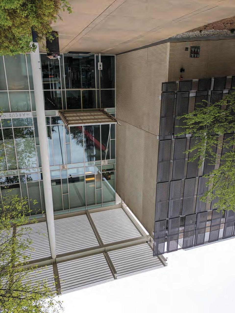
MARCUS NANOTECH BUILDING
MEDIA AND MODELING III
ADVANCED STUDIO I
[BREAK] TOWER PROJECT
SIFTING ECOLOGICAL RESPONSIBILITY
INTEGRATED BUILDING SYSTEMS I
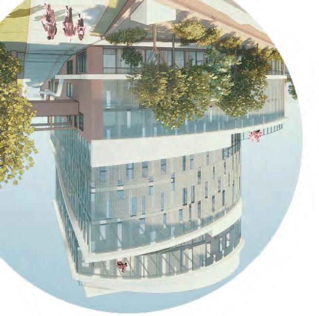
portman studio
ARTS
SQUARE (BLDG) professor; Harris dimitriopolis
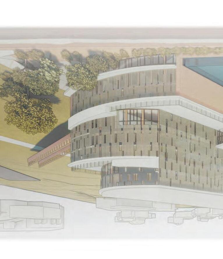
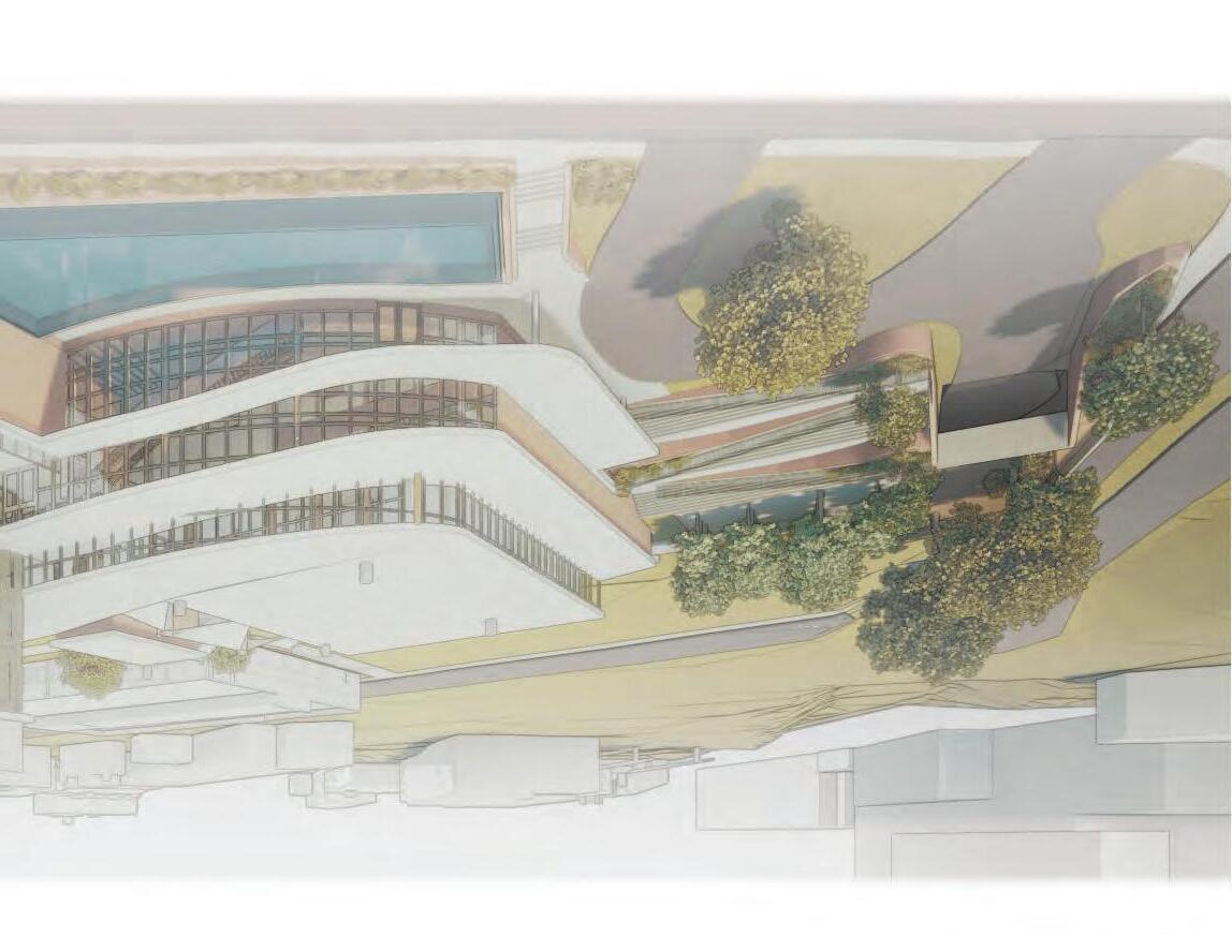
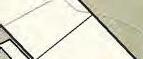
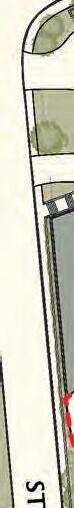
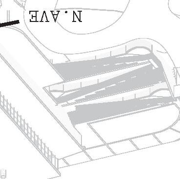
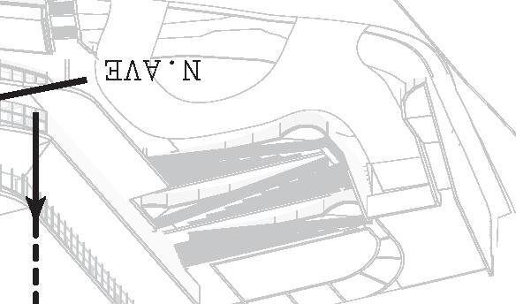
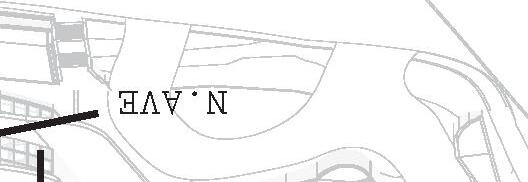
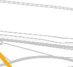
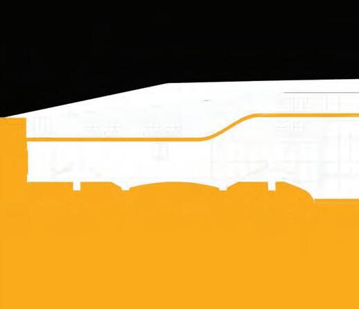
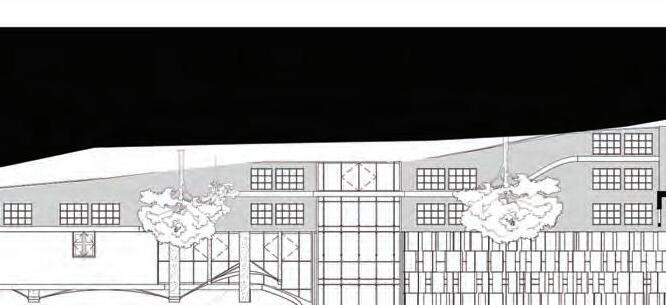
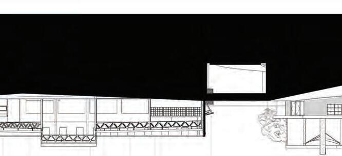
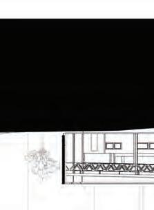
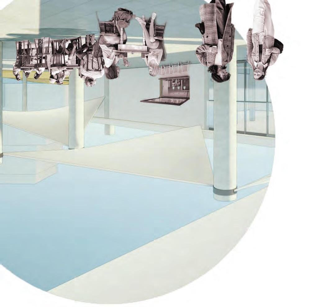
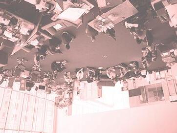
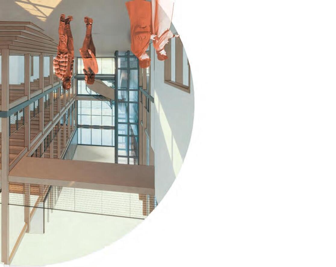
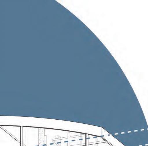
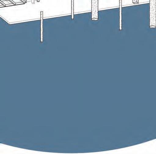
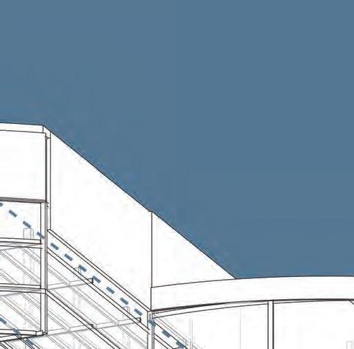
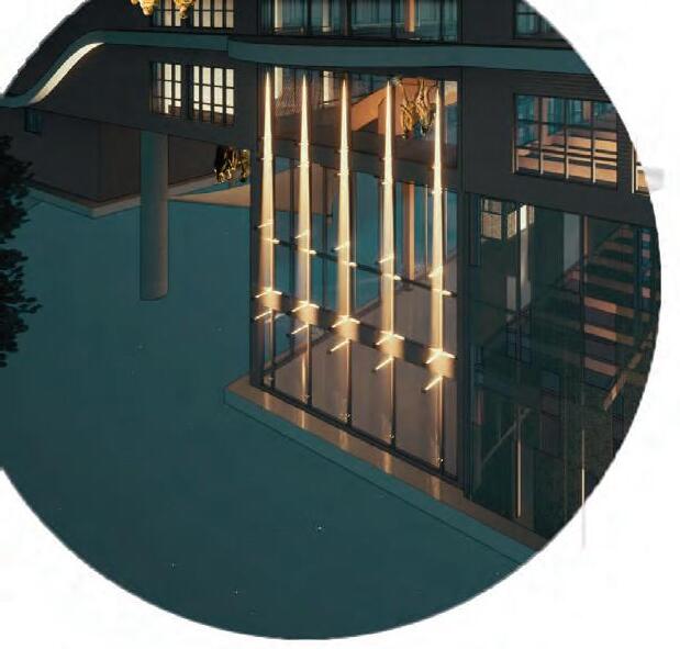
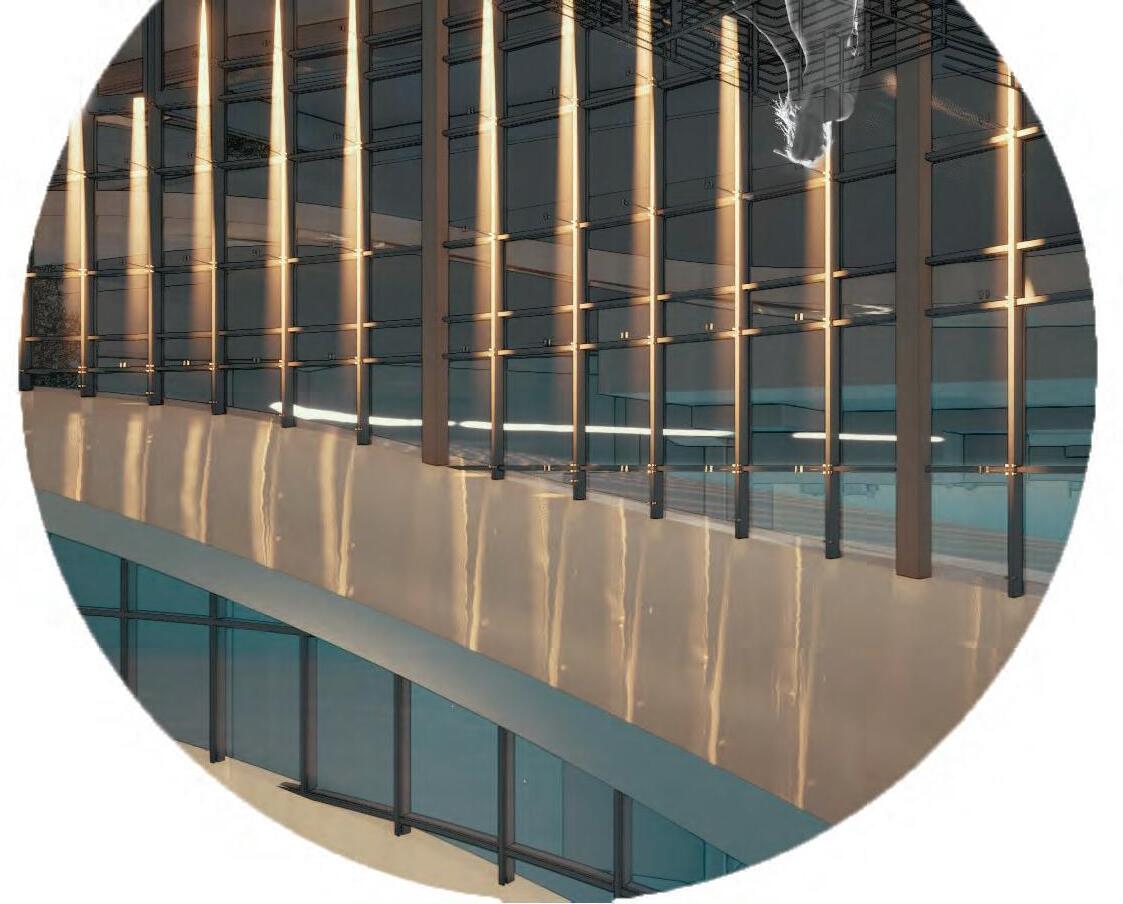
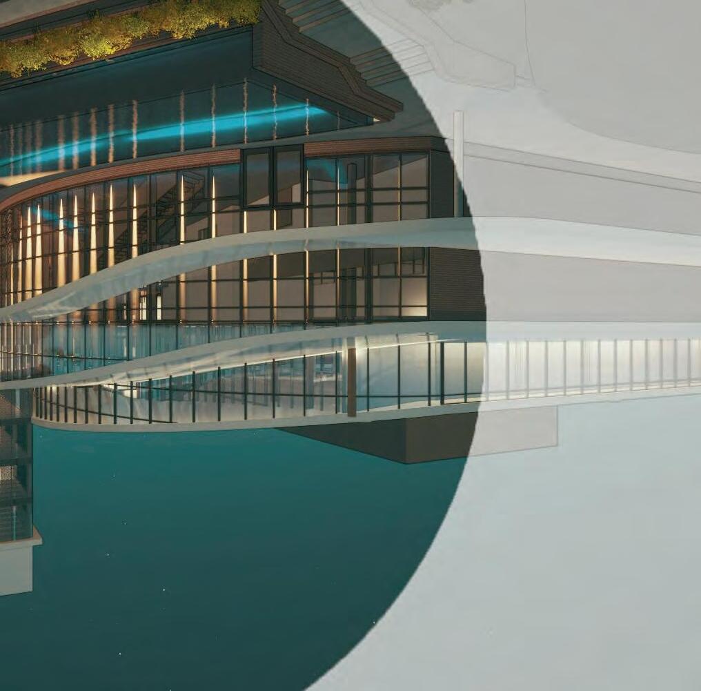
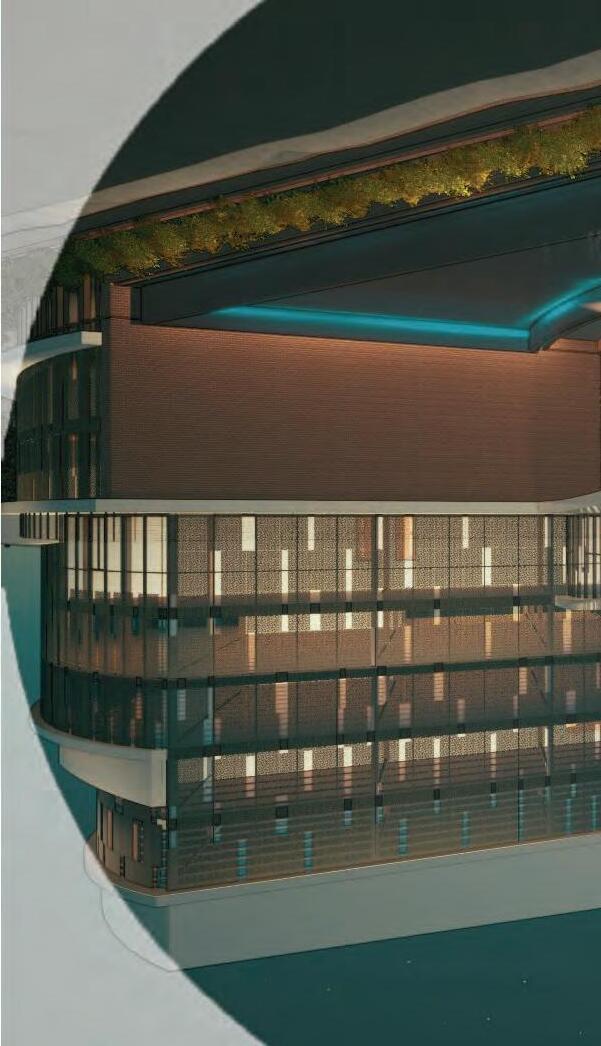
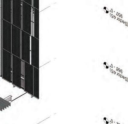
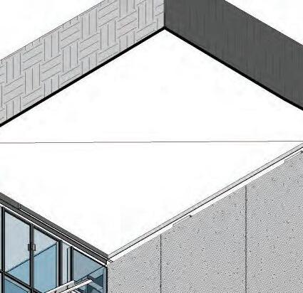
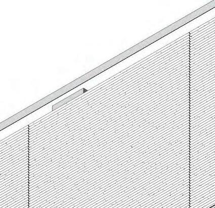
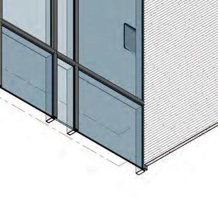
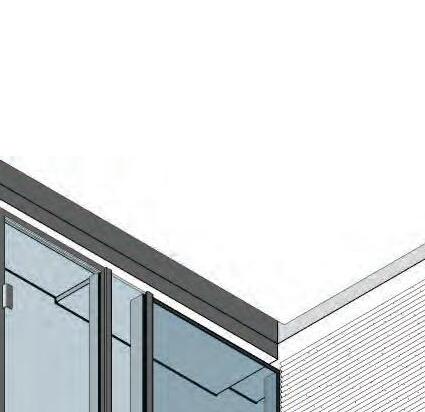
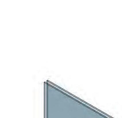
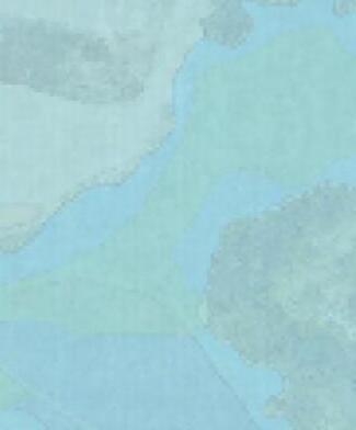
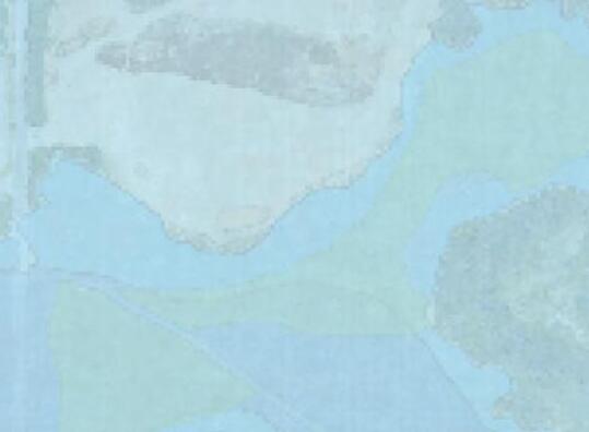
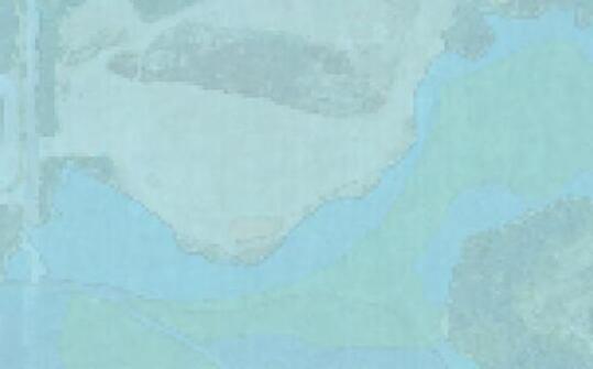
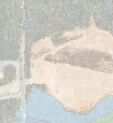
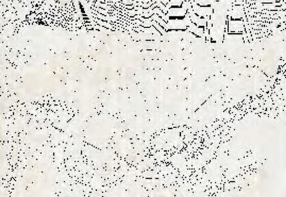
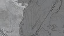
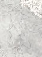
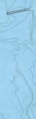
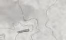
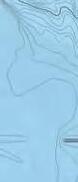
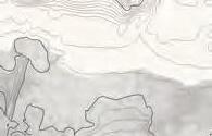
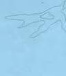
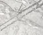
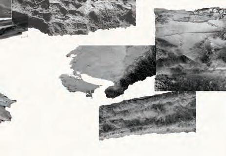
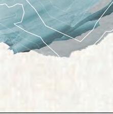
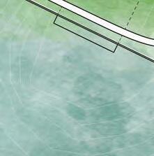
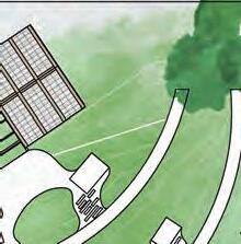
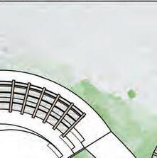
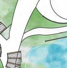
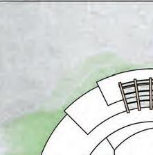
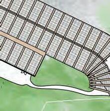
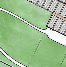
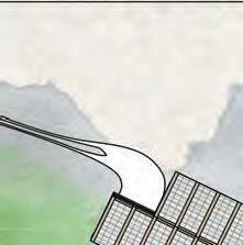
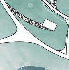
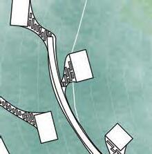
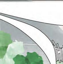
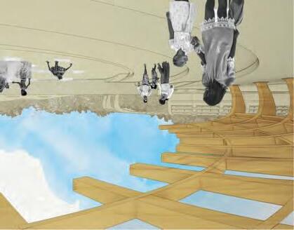
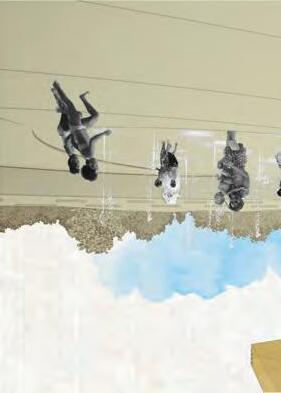
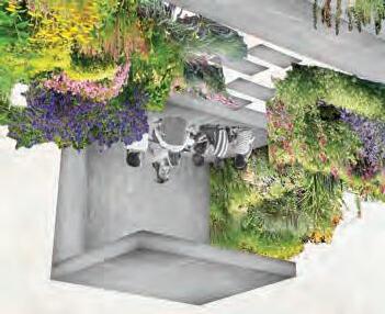
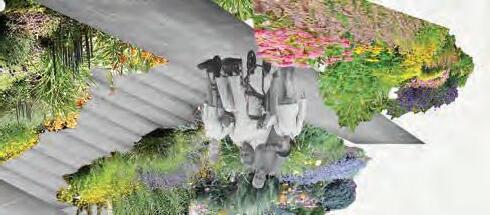
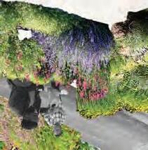
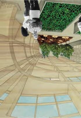
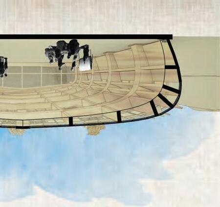
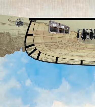
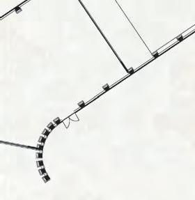
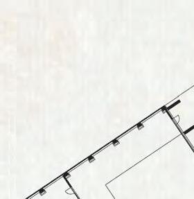
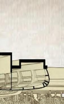
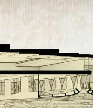
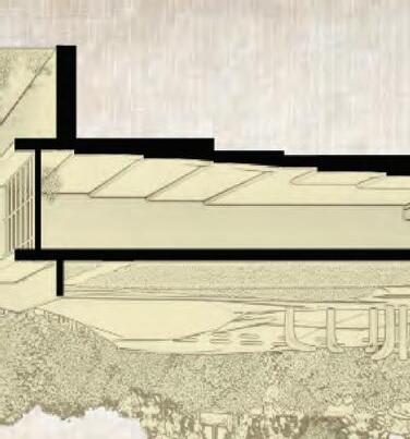
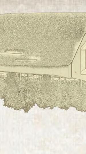
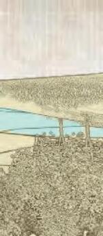
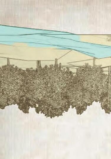
Located on a 7 acre piece of property, the Portman studio development aims to investigate a replacement of and expansion upon the Ferst arts center in both it’s physical capabilities and educational intentions. Perched on the edge of campus and bordering a rapidly growing part of the city, the program is to be diverse, the facilities accessible to the public as well as institutional interests.
Proposed is a building which fronts two prominant causeways of traffic, State St. and North Ave., each a critical vein of the campus and city respectively. This building provides ample stage presence for performances large and small and expounds upon those programs with digital, physical, and intellectual makerspaces to guide the future of the Arts in a way uniquely Tech.
“wallacest.”


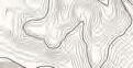
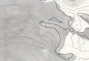
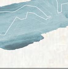
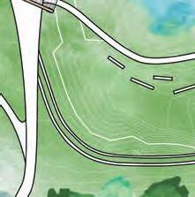
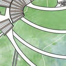
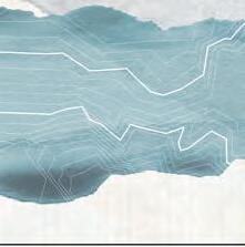
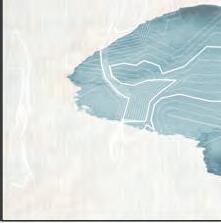
SITE
DEVELOPMENT
CIRCULATION
PARTI
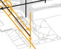
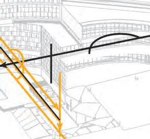
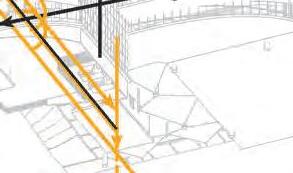
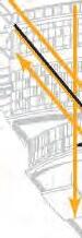


BUILDING


CAMPUS


CONNECTION


PERFORMANCE
DROP-OFF/PICK-UP
010 3050
010 3050
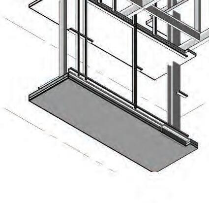
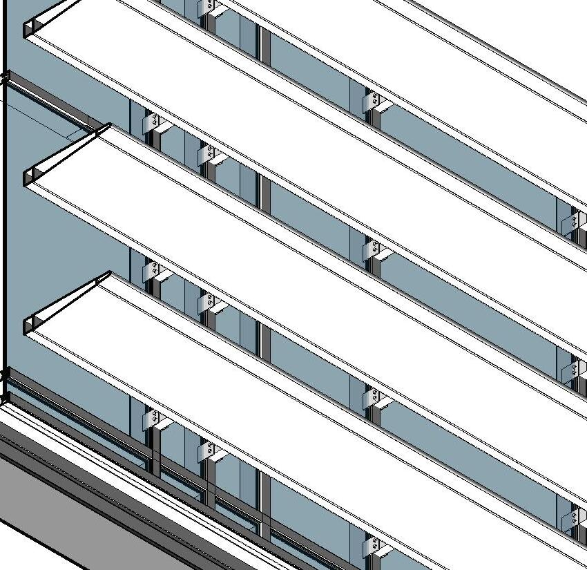
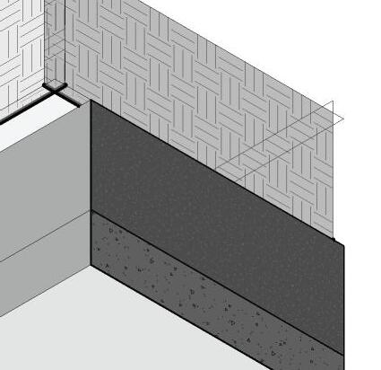
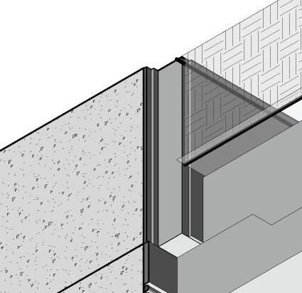
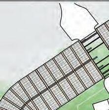
LEVEL(S) 4-8


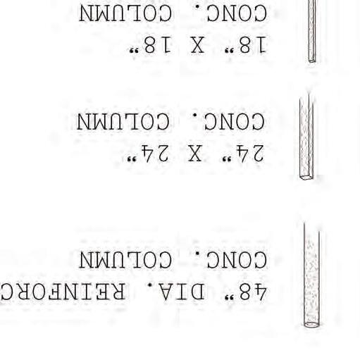

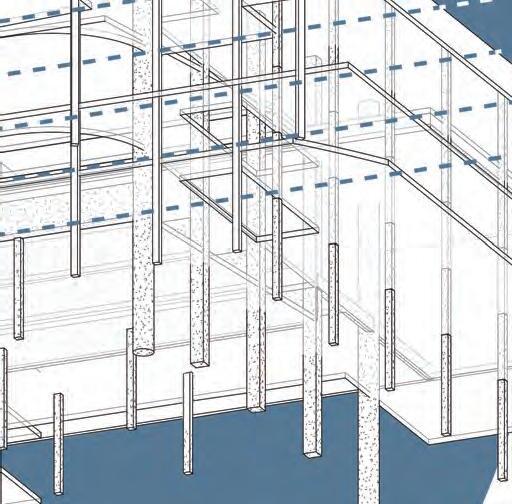
STRUCTURE DIAGRAM
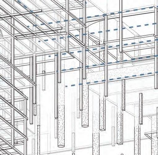
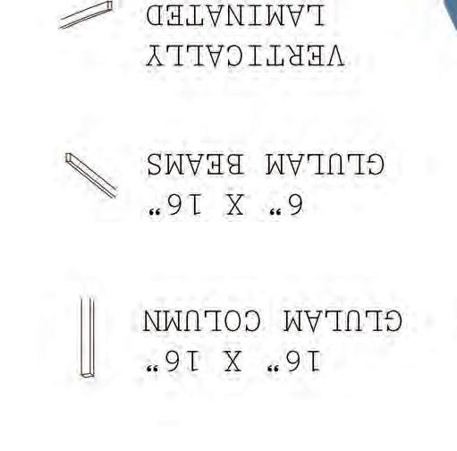
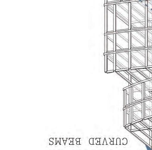

10” + 1’ PER FLOOR
ABOVE PLINTH SLAB
24” x 60”
POST-TENSION BEAM SPANNING 60’
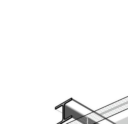
STEEL WF BEAM ELEVATION VARIES


MECH SCREEN AND PARAPET
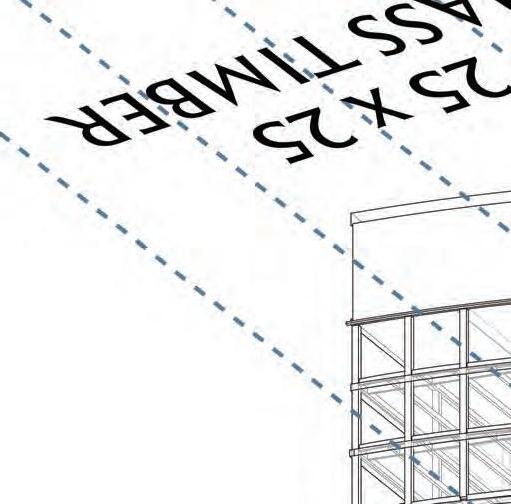
5.125” x 16.5” GLULAM BEAMS @ 5’ O.C.
STEEL TRUSS BEARING ON GLULAM COLUMN SPANNING 50’
DECK PAVERS ON CLT SLAB


LOAD BEARING CURTAIN WALL


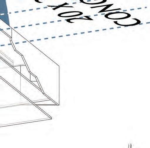
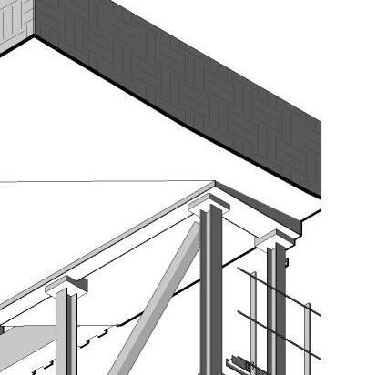
STRUCTURAL SECTIONS


BUILDING
PROFESSORS;
Karen Jenkins
Bryce Truitt
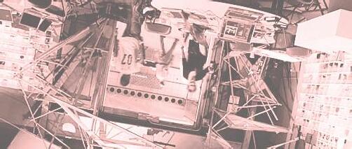
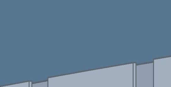
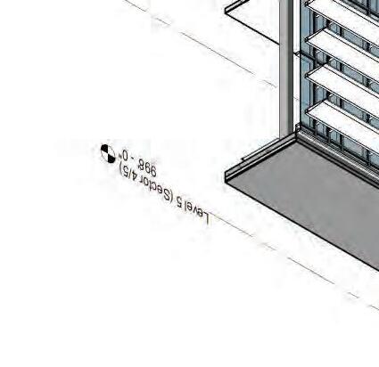
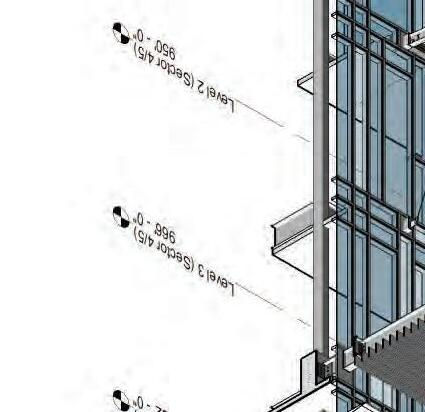
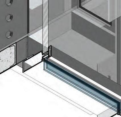
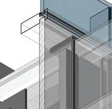
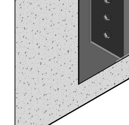
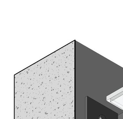
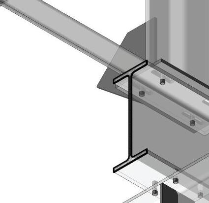
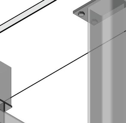
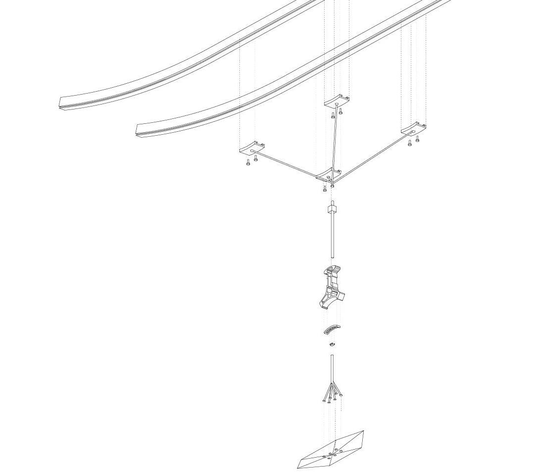
What follows is focused individual work from Phase III built upon a larger group contributed whole. The project is built in revit and was meant as an exercise in construction document comprehension and structural detailing.
Phase I&II Group Members: Ruby Anderson, Harrison Novak, & Carson Harris

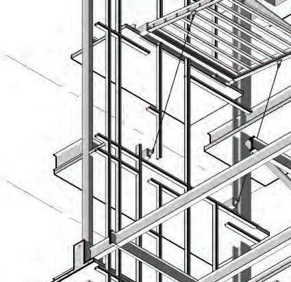
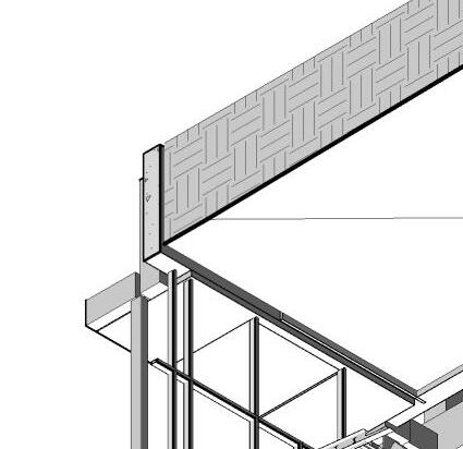

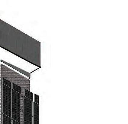

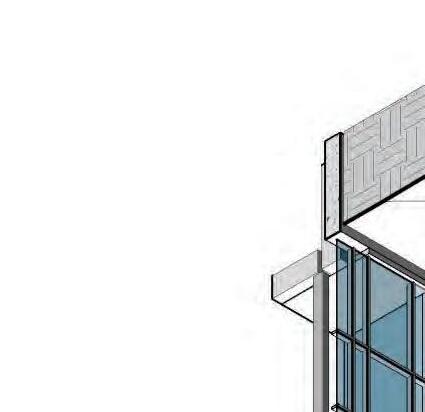

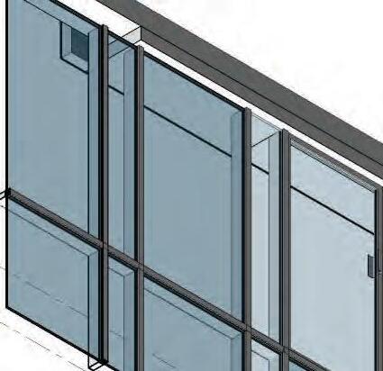

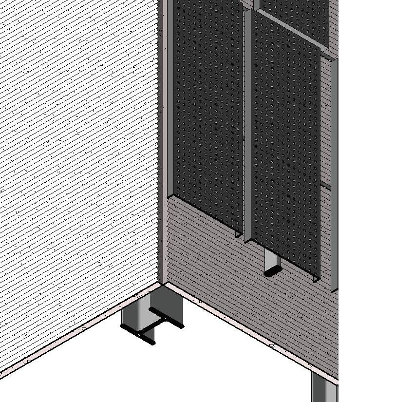

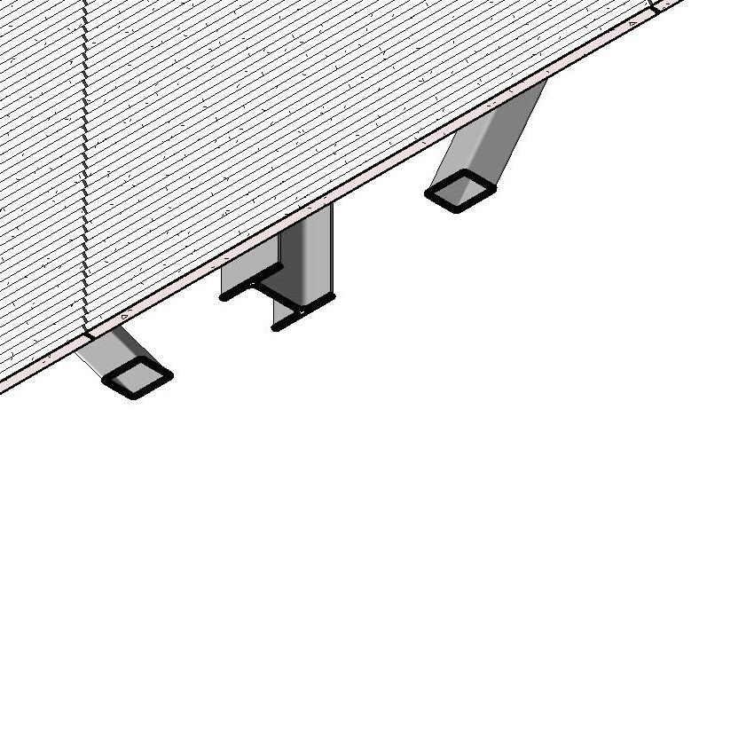
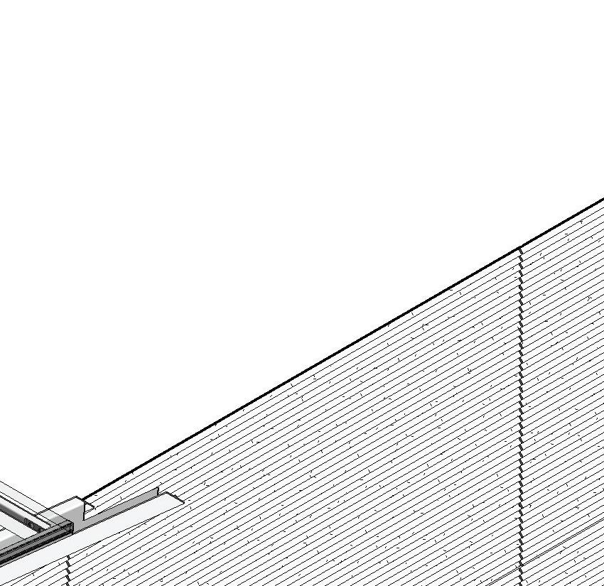

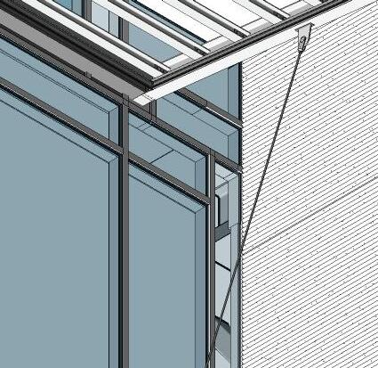
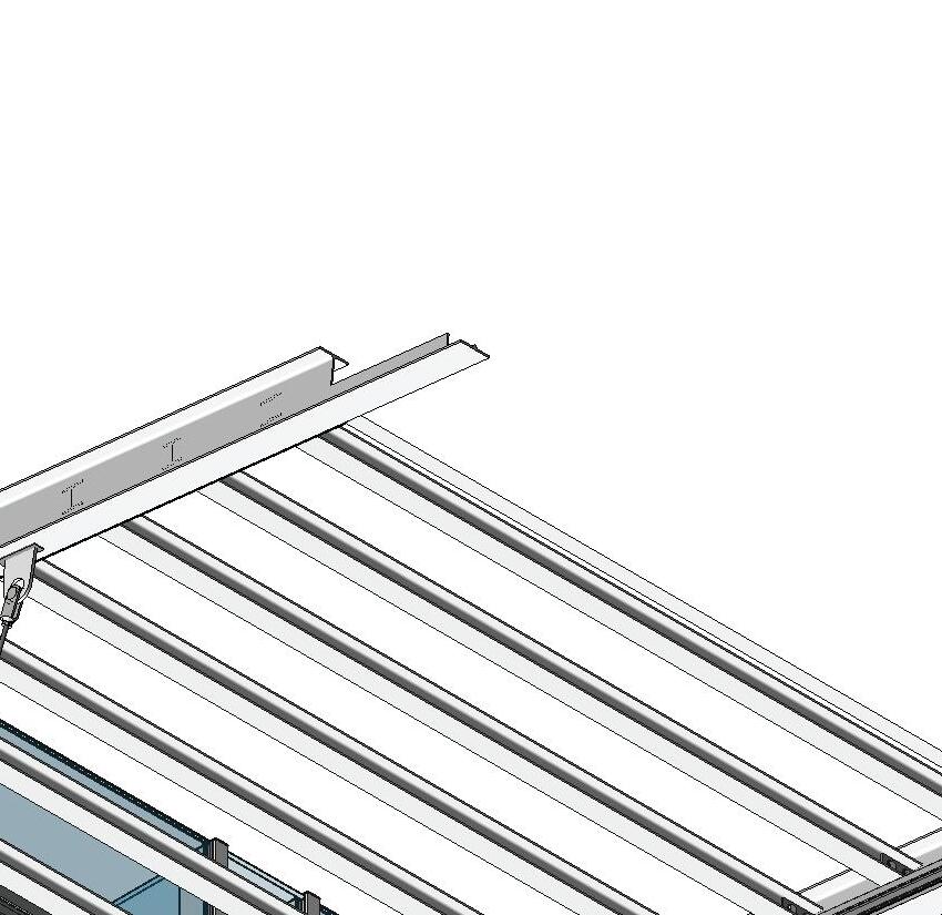
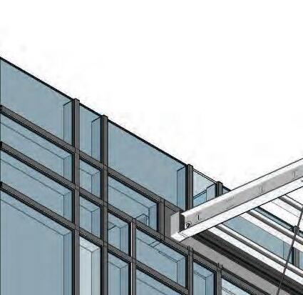


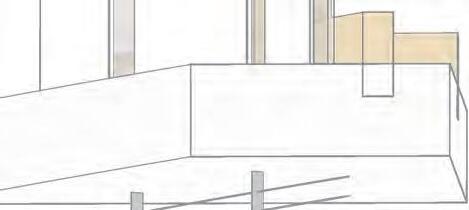
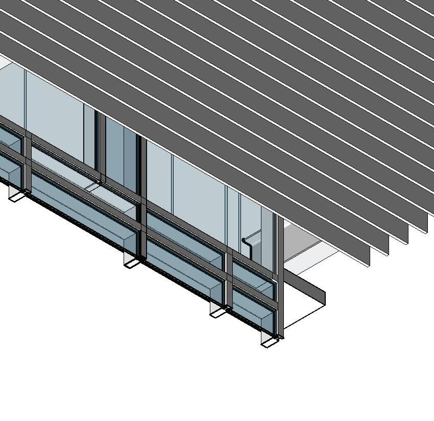
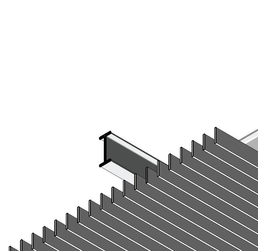
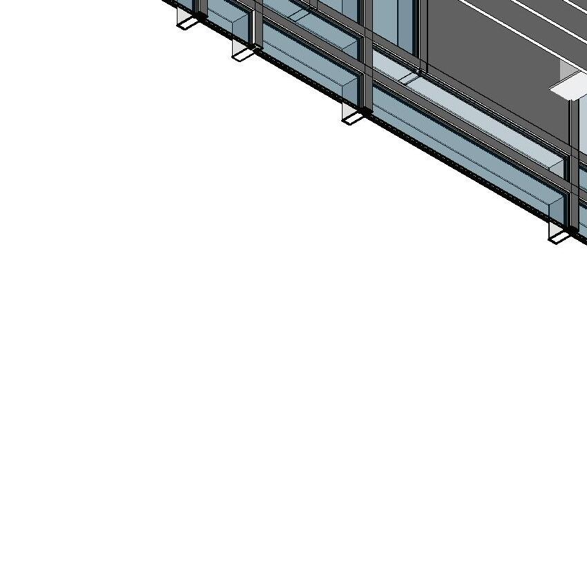
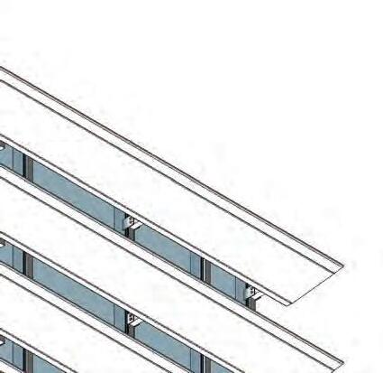
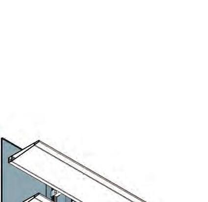
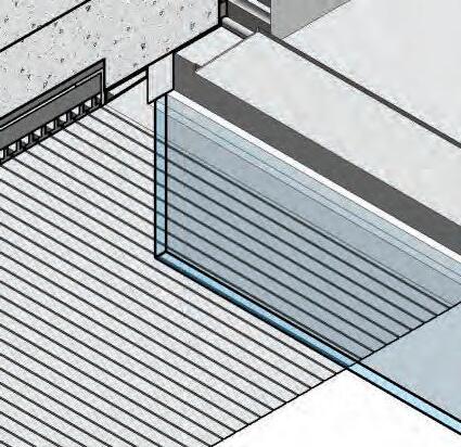
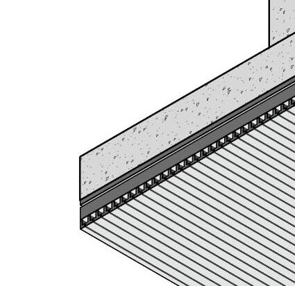
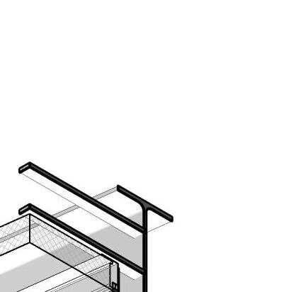
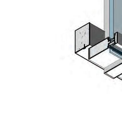
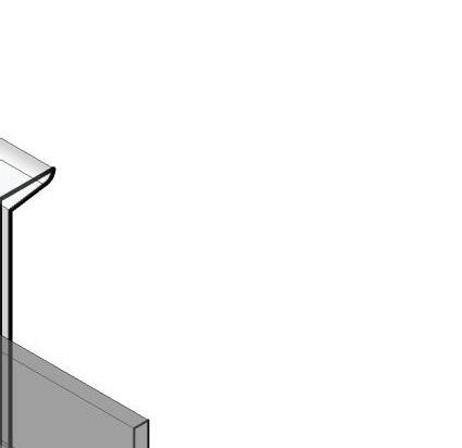
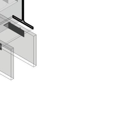
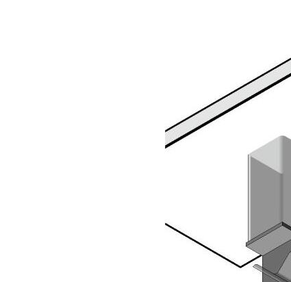
[2] METAL CANOPY STRUT ANCHORED TO BLDG STRUCTURE [1-A-333]
[3] STL WF BEAMS SUPPORTING A TRANSLUSCENT FIBERGLASS CANOPY [13-A-373]
[4] AESS W10 STL CANOPY FRAMING WITH STAGGERED COPING @ END [13-A-373]
[5] PRECAST PROFILED CONCRETE PANELS W/ EXPANSION JOINTS @ 12' O.C. [1-A-323]
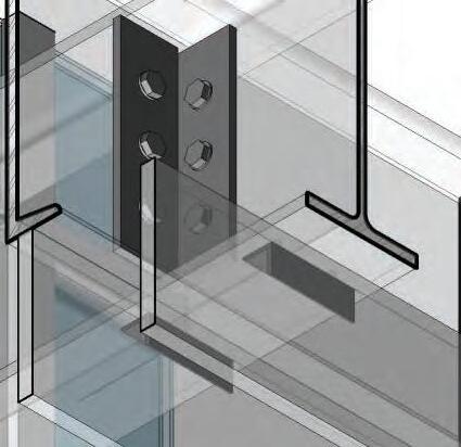
[6] W14x90 STL COLUMN [1-S-213]
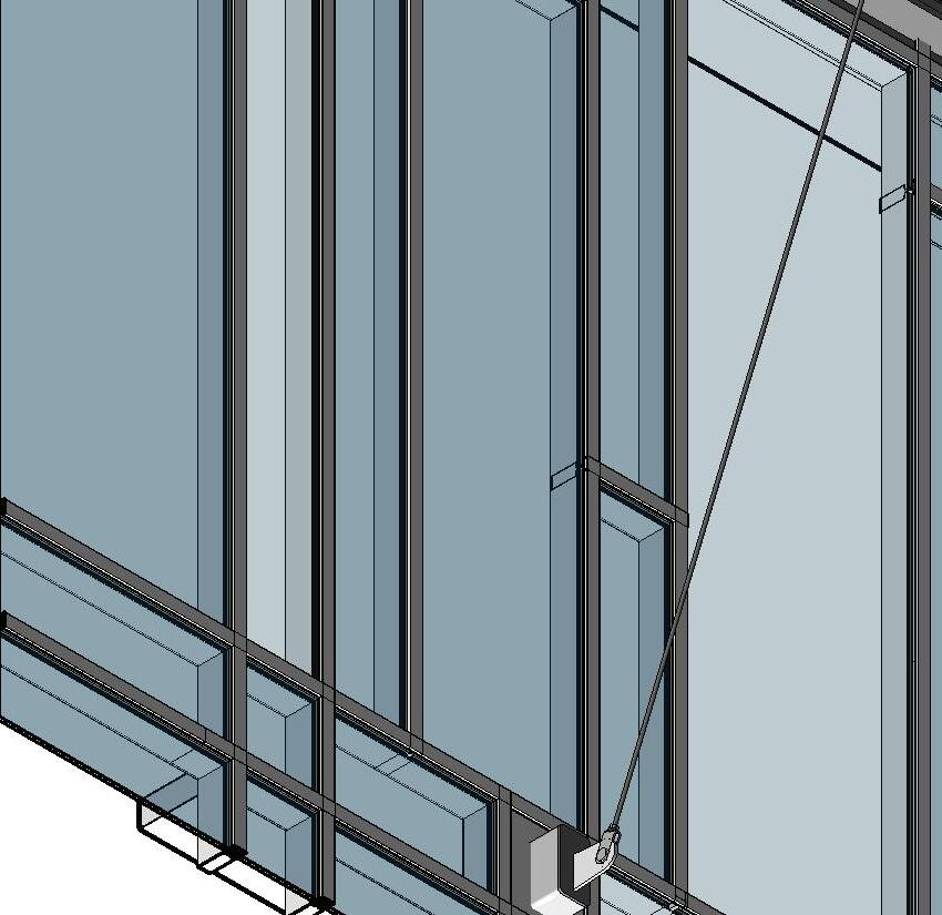
[7] HSS 8x8 BRACED FRAMING [7-S-520]
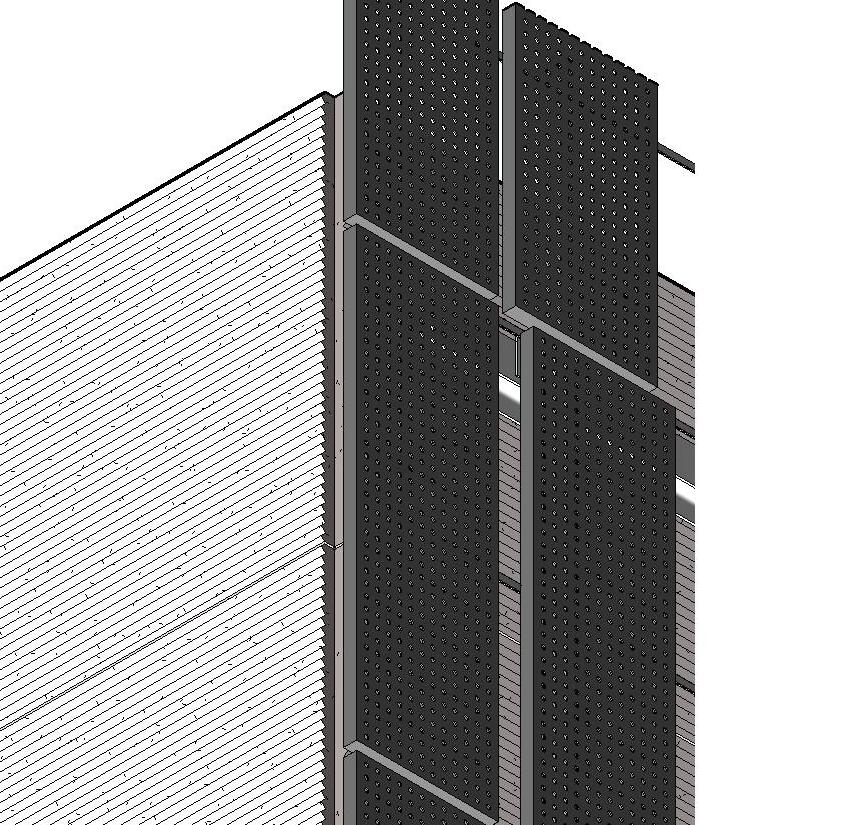
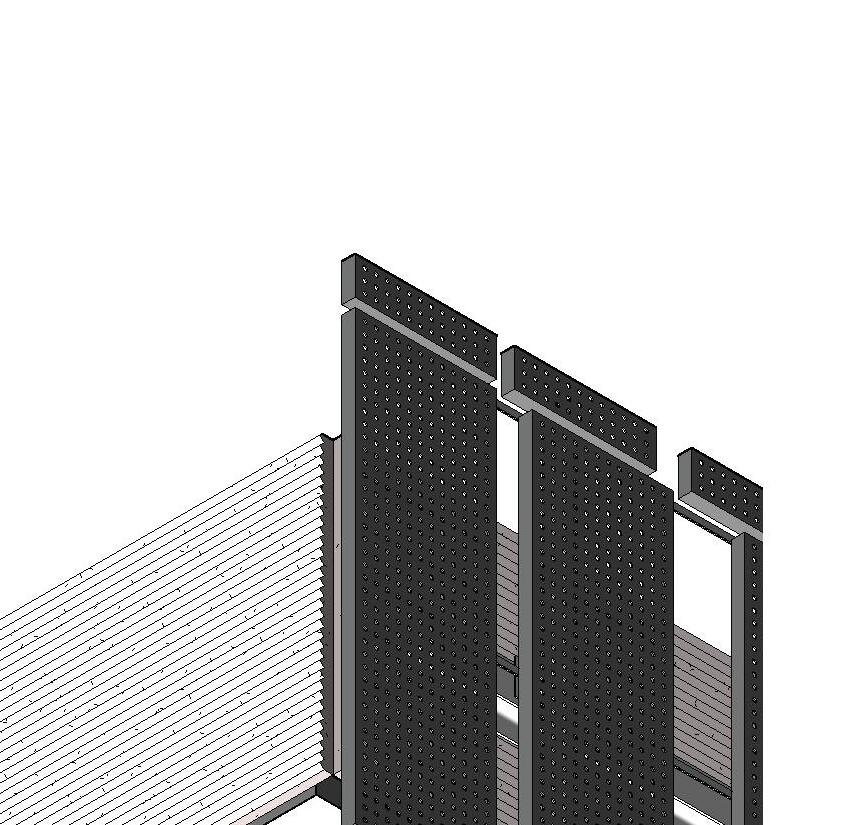
[8] PERFORATED COPPER PANELS MOUNTED ON ALUM SUPPORT FRAMING [3-A-331]
[9] PREFIN ALUM VERTICAL HSS MULLION ON STL GIRTS [3-A-331]


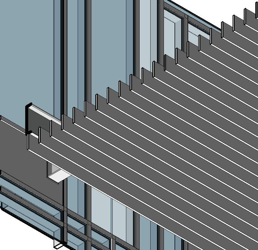
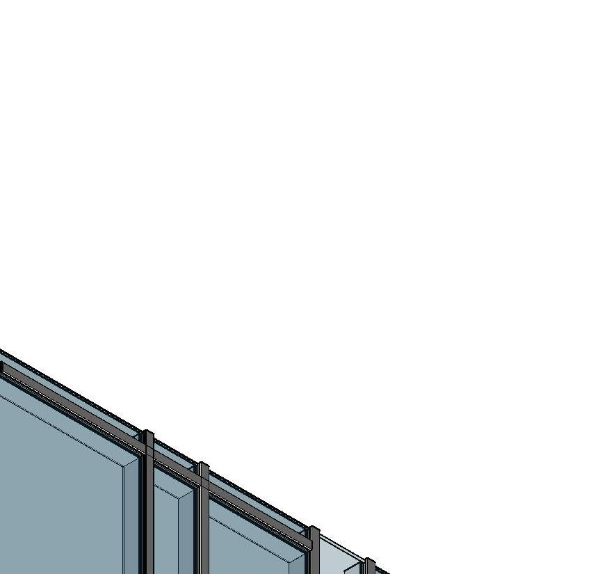


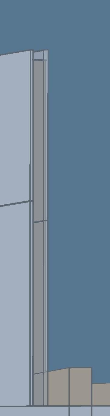
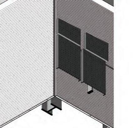
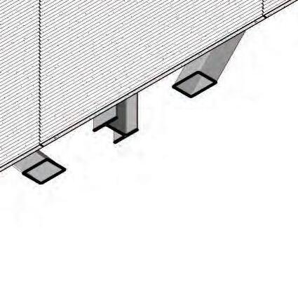
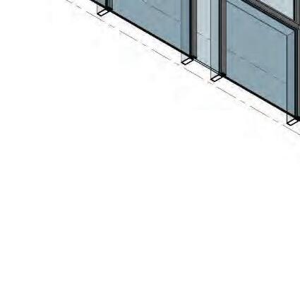
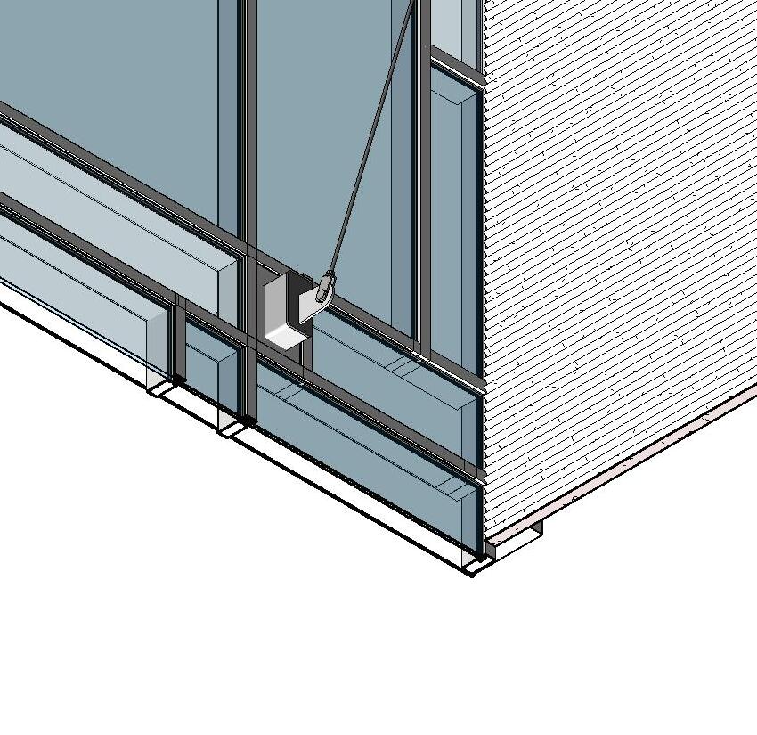
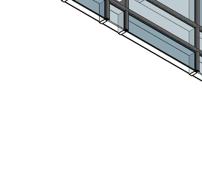
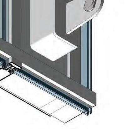
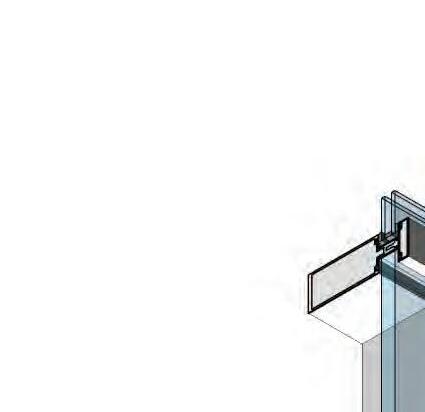
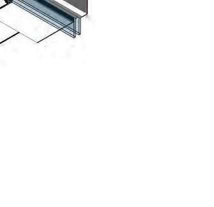
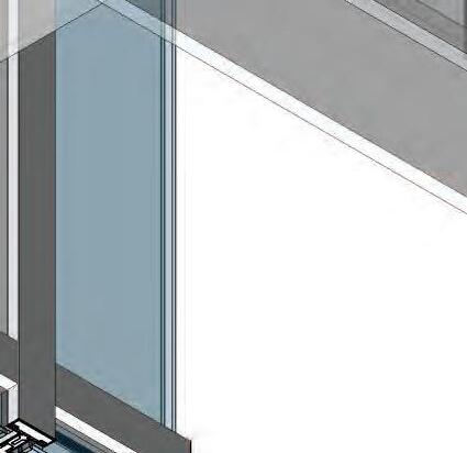
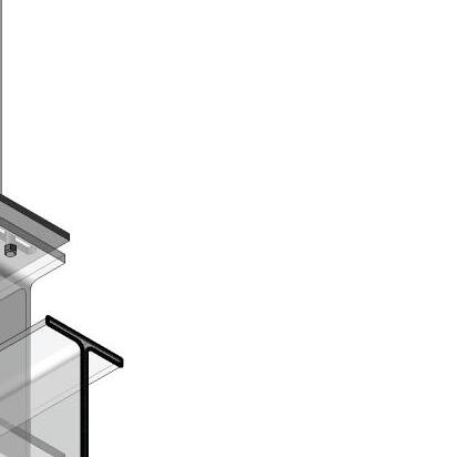
[1] DOUBLE GLAZED CURTAIN WALL W/ ITERMED. MULLION LOCATIONS [2-A-304]
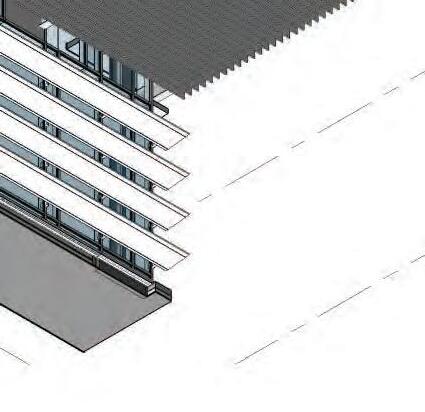
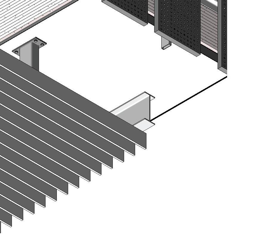
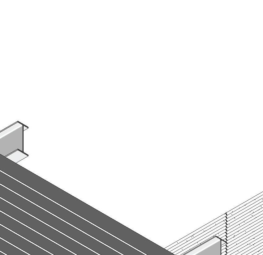
[2] TRELLIS 2x10 PREFIN ALUM TUBES ON STRUCT W18 STL BEAMS [1-A-333]
[3] HSS 10x6 COLUMN MOUNTED TO WF STL ROOF BEAM [6-S-245]
[4] LL 4x4 BRACE [6-S-245]
[5] PRECAST PROFILED CONCRETE PANELS W/ EXPANSION JOINTS @ 12' O.C. [1-A-323]
[6] HSS 6x6 SUPPORT COLUMN WITH CAP AND GUSSET PLATE TO RECIEVE BRACE [6-S-245]
[7] PERFORATED COPPER PANELS MOUNTED ON ALUM SUPPORT FRAMING [3-A-331]
[8] PREFIN ALUM VERTICAL HSS MULLION ON STL GIRTS [3-A-331]
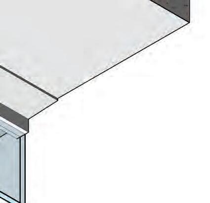
[9] ROOFING MEBRANE AND 4" RIGID INSULATION ON SLOPED CONCRETE SLAB [2-A-323]
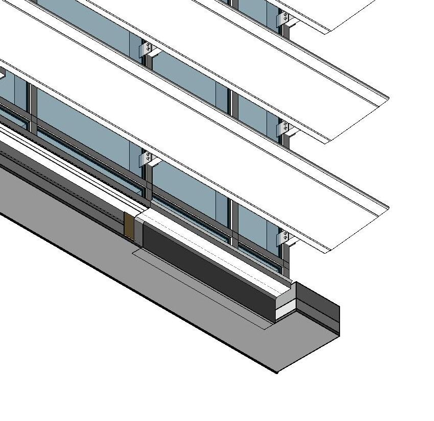
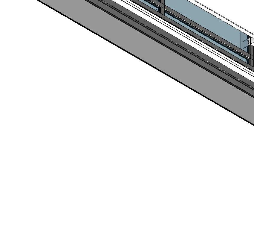
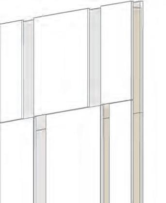
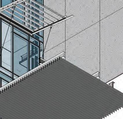
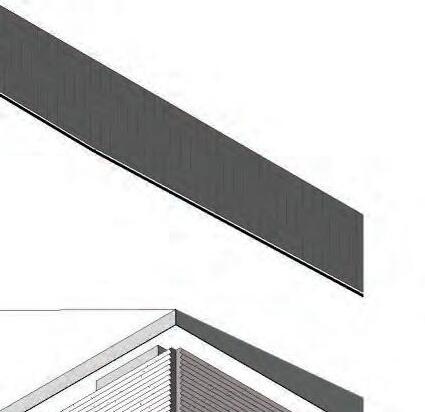
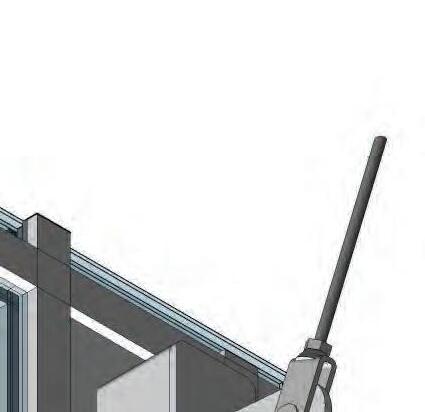
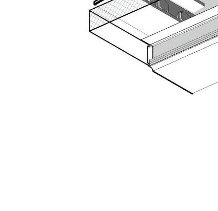
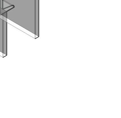
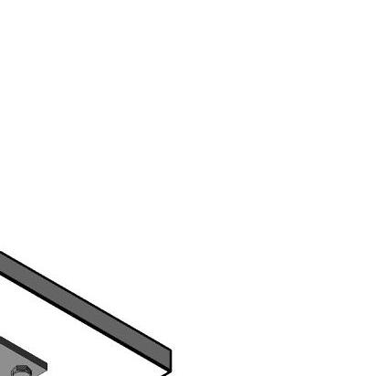
[1] DOUBLE GLAZED CURTAIN WALL W/ ITERMED. MULLION LOCATIONS [2-A-304]
[2] ALUM LOUVERED SUNSCREEN MOUNTED TO CURTAIN WALL MULLIONS [1-A-333]
[3] ROOFING MEBRANE AND 4" RIGID INSULATION ON SLOPED CONCRETE SLAB [2-A-323]
[4] PREFIN MTL GRAVEL STOP/FASCIA TYP. [1-A-333}


Tori Ellis in collaboration with Ruby Anderson & Harrison Novak
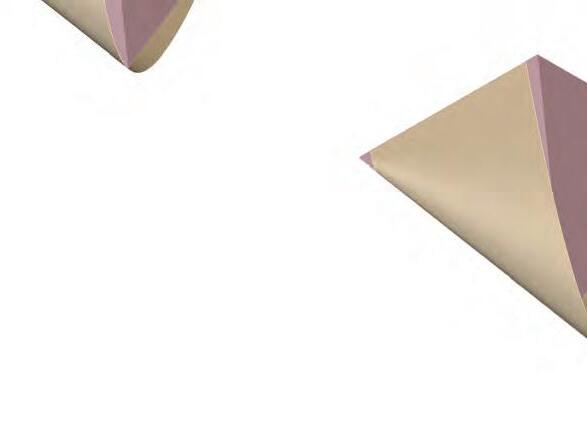
Which base triangle provides the most usable area?

Base area set to 3,000 for all
First Floor Head Height @ 7’-0”
Second Floor Head Height @ 17’-0”
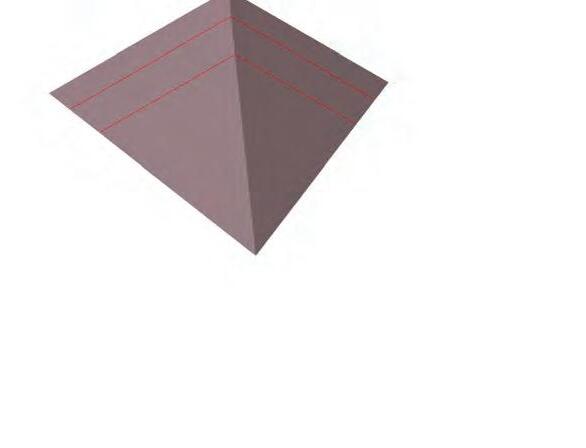
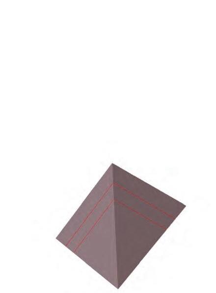
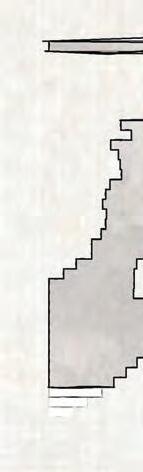
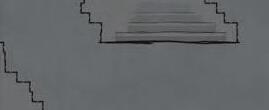
Massing Operation Diagram | Base Shape
First Floor HH; 2429.98
Second Floor HH; 1719.78
First Floor HH; 2430.02
Second Floor HH; 1719.81
First Floor HH; 2430.04
Second Floor HH; 1719.83
CONCLUSION:
Each provides the same usable area, so we decided to proceed with the right triangle for stuctural simplicity in the right angle and to mitigate at least one accute corner. Exploration of top point location would be beneficial next.
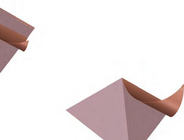
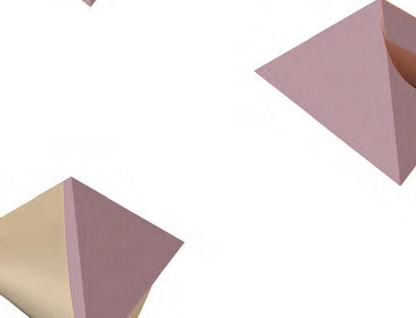
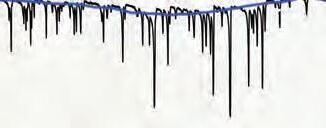
How can a second skin insulate and Passively heat the building?
Massing Operation Diagram | Veil
CONCLUSION:
This veil would be effective at heating a singular room in a greenhouse lab/exhibit. This warmer air coudl then be contained or let out to rise into the rest of the space. Selective thermal mass could also be explored.
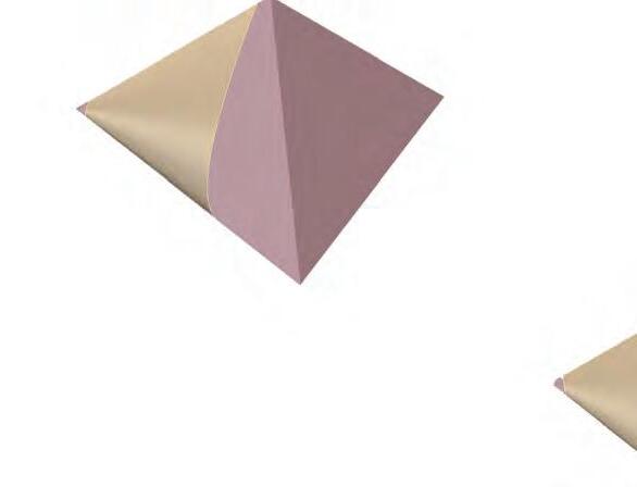
How does the offset of the veil affect the efficiency of the Trombe wall?
What tile configuration offers best coverage and assembly efficiency?
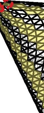
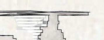
The Trombe wall does not require a large air gap. The smaller gap requires less material. More panels reduces the length of the members creating easier transport. The inherent strength and stability of the triangle form provides for our structural efficiency objective.
Largest Panel Size (Area): 2.6 sqft Longest Member Size (Length): 10 feet


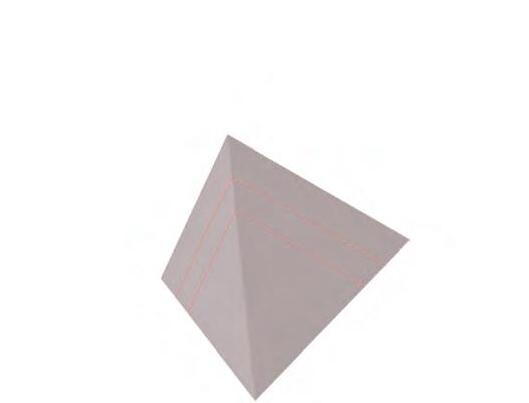
Tessellation Diagram | Mass


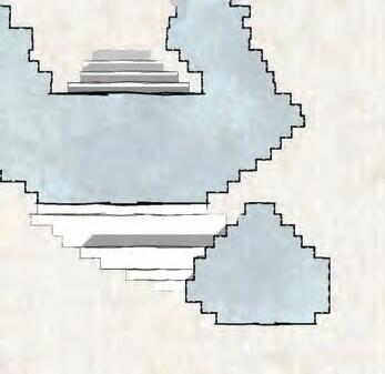
TILE MAPPING
Surface Area: 2185
Total Panel Area: 2535
Unique Panel Areas: 13
CONCLUSION:
Paneling coverage is 100% and only one tile size is needed per side. Due to the uniformity and orientations of the panels in this mapping, substitutions for window or thermal mass material under the veil can be easily accomodated, and will produce less material waste in the factory. A single panel type can also free up funds for more unique texture.
Material Panel - invesigated as local spruce CLT, rammed earth, and fired masonries.
Trombe Wall - Passive heating of the mass below with the veil providing a greenhouse effect. Orientation of the building is explored to confirm maximum gain.


Baseline
Model | Final Framework

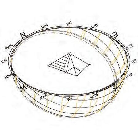
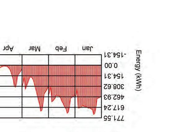
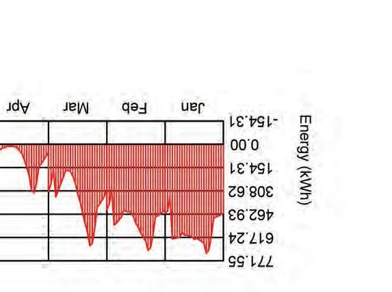
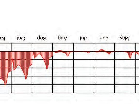
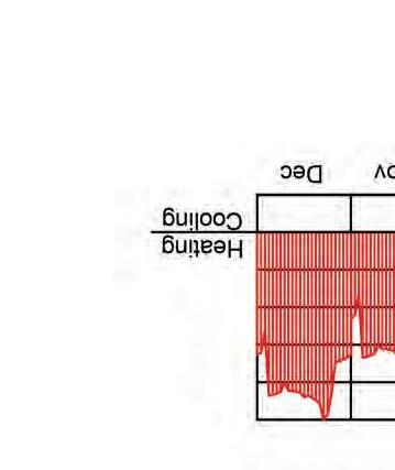
WEST ORIENTATION
Cooling: 0.863891
Heating: 252.635421
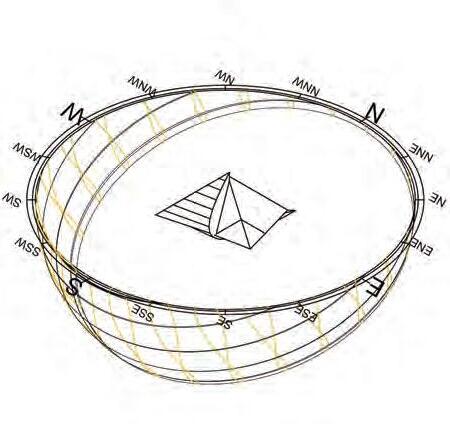
SOUTH ORIENTATION
Cooling: 0.78057
Heating: 221.694436
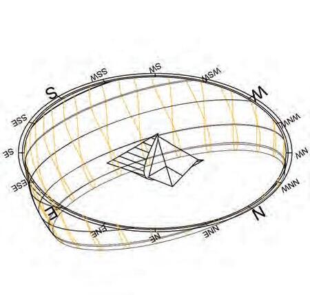
EAST ORIENTATION
Cooling: 0.863891
Heating: 248.792426
CONCLUSION:
For our materials we decided to use aluminum framing instead of steel framing because of its strength to weight ratio. There is a negligible difference in the effect on heating loads in the building.
For our panel material, we discovered that rammed earth is 1% more energy efficient than our original material, CLT. Fired masonry is 1% less energy efficient than the CLT panels.
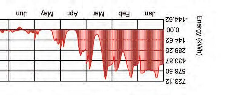
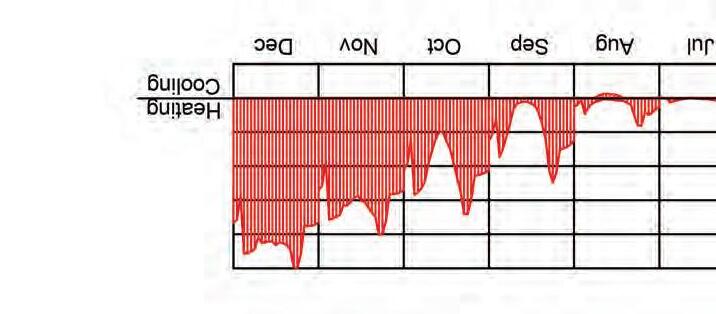
ALUMINUM FRAMING
Cooling: 0.701546
Heating: 218.62058

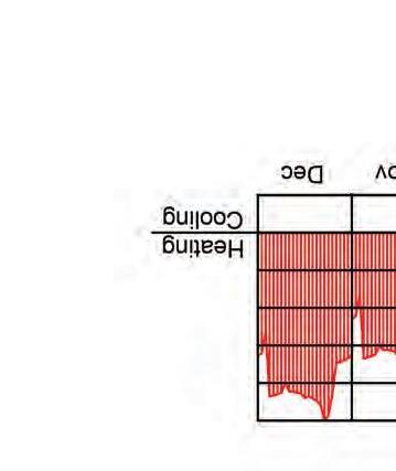
CONCLUSION:
For our materials we decided to use aluminum framing instead of steel framing because of its strength to weight ratio. There is a negligible difference in the effect on heating loads in the building.
For our panel material, we discovered that rammed earth is 11% more energy efficient than our base material of CLT. Fired masonry is 7% less energy efficient than the CLT panels. FIRED MASONRY
Cooling: 0.628228
Heating: 222.935661 Design Analysis Diagram
Cooling: 0.700928
Heating: 218.61058
Panels - higher thermal mass for the panels by using rammed earth makes the builing 11% more enery efficient.
Framing - aluminum framing instead of steel framing because of its strength to weight ratio. There is a negligible difference in the effect on heating loads in the building.
Design Iteration Diagram | Final Analysis
Trombe Wall - Passive heating for the trombe wall is optimized by orienting the building to the east.

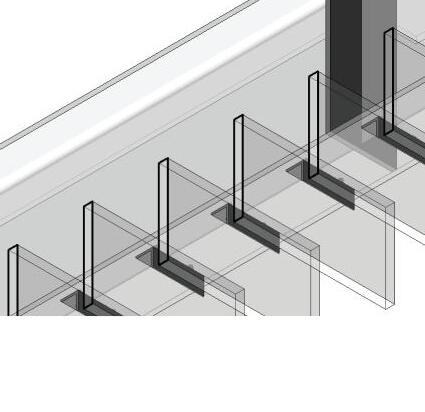
A Panel:
A Panels are scheduled on the intersection of the Upper Letter and Number Grid (dashed grey) at the panel centroid. The panel centroid connects to structural members that connect back to the lower structural grid.
*panel shown above 6_E
B Panel:
B Panels are scheduled on the intersection of the Upper Letter and Number Grid (dashed grey) at the panel corners. These four corners have structural members that connect back to the lower structural grid. There are half panels on the first and last rows (along
*panel shown above 4-5_EF

A Panel: (minimum/maximum)
Panel Material: Low E glass
Structure Material: Aluminum
Area: 3.70 sqft. - 51.59 sqft.
Weight: 0.19 lbs. - 2.59 lbs.
Letter Span: 3.23 ft. - 5.3 ft.
Number Span: 1.44 ft. - 20.86 ft.
*Letter span indicates spans between upper letter grids (DE, EF, etc.). Number span indicates spans between number grids (1, 2, etc.)


B Panel: (minimum/maximum)
Panel Material: Low E glass
Structure Material: Aluminum
Area: 1.28 sqft. - 51.20 sqft.
Weight: 0.06 lbs. - 2.57 lbs.
Letter Span: 3.21 ft. - 4.70 ft. (half panels not included in this dimension)
Number Span: 0.47 ft. - 21.64 ft.
*Letter span indicates spans between letter grids (A, B, etc.). Number span indicates spans between number grids (3-4, 5-6, etc.)
*Red dash on key view indicates half panels that occur on the first and last rows
Assembly
A Panel
Structural Taxonomy Locations
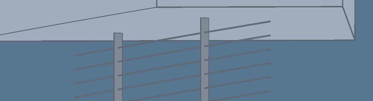
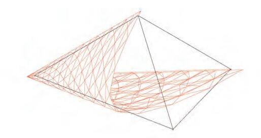
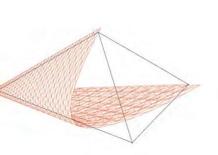
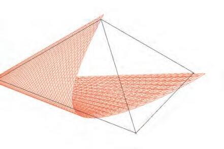
With the symmetry of the equilateral triangle, the structural members are duplicated across the axis. The members tend to increase in size as the veil stretches up and towards the front of the tetrehedron.
Right View
Left View
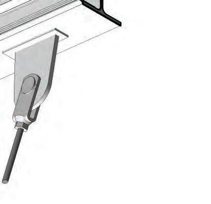
GLASS PANEL CONNECTORS W/ ANGLE REGULATION
Hinged Connection to Extruded Aluminum Rod
SLIDER FOR ALUMINUM SADDLE EXTRUSION
Welded Connection to Extruded Aluminum Rod
ALUMINUM SADDLE EXTRUSION
ALUMINUM Y-MULLION W/ ALUMINUM SADDLE EXTRUSION
ALUMINUM EXTRUSION ROD
Steel Backer With Bimetallic Strip @ Weld To Aluminum
ALUMINUM BRACING
Variable Length Depending On Panel Grid Location
LINEAR STEEL BEARING BLOCK SLIDER W/ HEX BOLTS
TYPICAL STEEL HOOP RAIL
ADV. STUDIO
SIFTING ECOLOGICAL RESPONSIBILITY PROFESSOR;
KIM STEINER

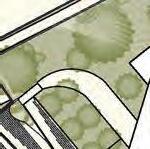
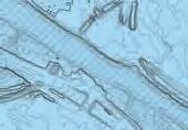
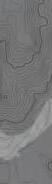
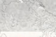
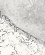
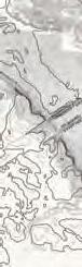
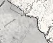
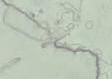
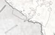
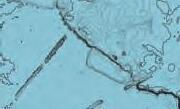
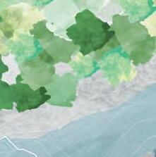
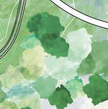
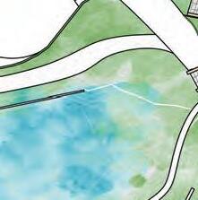
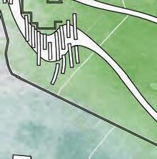
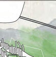
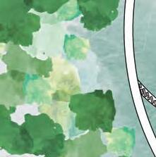
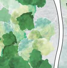
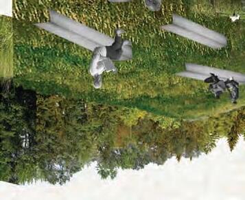
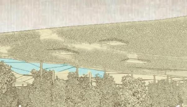
BY SIFTING THROUGH AND REDUCING THE DENSITY OF THE CURRENT ECOLOGY OF THE SOUTH ROVER AT THE POOLE CREEK JUNCTION, FLOODPLANS RISE TO THE SURFACE. INTRODUCING ECOSYSTEM STRATEGIES SEEN FURTHER DOWN THE RIVER TO CONTROL THESE FLOOD PLAINS WILL HELP MAINTAIN THE RIVER’S FORM AND PROTECT THE INDUSSTRY AJACENT TO THE AREA. BY EDUCATING THE COMMUNITY IN HOW THESE ECOSYSTEMS FUNCTION, AS WELL AS PROVIDING THE TRAINING AND TOOLS TO NURTURE IT THEMSELVES, THE RIVER, AND IT’S FLOODING, CAN BE BETTER CARED FOR AND MANAGED LOCALLY. tHROUGH LEADING BY EXAMPLE, AS WELL AS PROVIDING RESOURCES TO OTHER SIMILAR SITES, THS DESIGN WILL ACT AS A CATALYST TO OTHER RIVER RECLAMATION SITES.


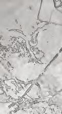
WATER


SOIL TYPOLOGY IS KEY TO SLOWLY SIFT THE WATER AND NUTRIENTS BACK INTO THEIR ENVIRONMENT. COMPOSTING IS AN ACCESSIBLE AND SCALABLE MEANS TO REVITALIZE LAND.


FLORA
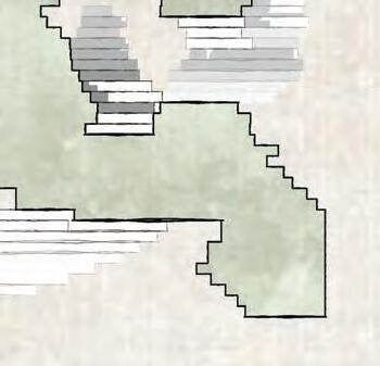

COLLECTING LAND RUNOFF AND RIVER OVERFLOW IN PONDS TO BE SLOWLY REINTRODUCED UNDER SAFER CIRCUMSTANCES. REUSING ALL AVAILABLE GREYWATER TO PROVIDE FOR THE PLANTS.

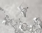
CULTIVATING DIVERSE ECOSYSTEMS THAT SIFT FLOODING THROUGH THEM HELP PROTECT THE NATIVE FOREST FROM UNDERCUTTING AND UPROOTING, AND LOCAL HOMES FROM FLASH FLOODING.


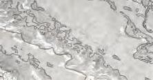
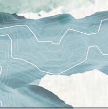
FLOODWATER DIVERSION DIAGRAM


RIVER HEIGHT VARIANCE


RIVER SOUTH RIVER


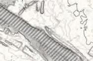


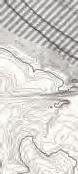


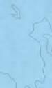


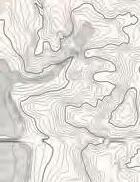


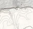


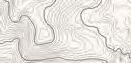
SOUTH-OCMULGEE-ATLAMAHA RIVER FLOODING


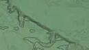


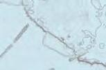


ATLAMAHA RIVER
OCMULGEE


ATLAMAHA RIVER
OCMULGEE RIVER
SOUTH RIVER


POOLECREEK
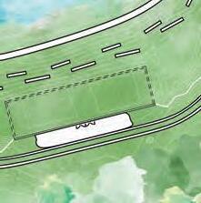


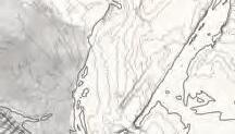
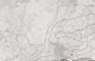
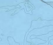
WET MEADOW PLAY FIELD WATER COLLECTION & DISTRIBUTION
COMPOST RECEIVING AND STORAGE
SOUTH RIVER
CONSTRUCTED WETLANDS AMPITHEATER


FUTURE SOUTH RIVER GREENWAY
FUTURE POOLE CREEK GREENWAY


TERRACED GARDENS
PROGRAM RENDERS

PARK ENTRANCE

COMPOSTING EXHIBITION
FOUNTAIN PAVILLION
BENCH HILL
NURSERY

VERMICULTURE PIT
COMPOSTING EXHIBITION
DISTRIBUTION CENTER AERATION AND STORAGE SHED ENTRANCE
MAINTENANCE AND SUPPLIES

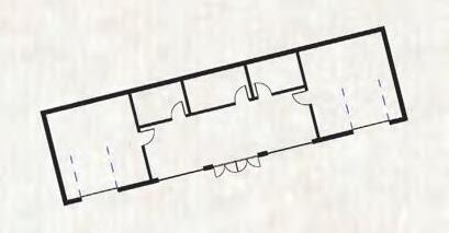
COMPOST FLOOR PLAN
MAINTENANCE GARAGE
“RIVERWALK”
STUDY STEPS CLASSROOM/ EVENT SPACE [BELOW]
VOLUNTEER MEETING ROOM FRONT DESK/ CHECKOUT SHALLOW NURSERY BEDS DEEP NURSERY BEDS
WATER COLLECTION SYSTEM STORAGE AND RESTROOMS
HYDROPONICS LAB
GERMINATION EXHIBIT WETLANDS CLASSROOM
ORDER PROCESSING AND DISTRIBUTION
MATERIALS STORAGE
SHED FLOORPLAN NURSERYFLOOR PLAN
PROGRAM AND SITE ENGAGEMENT


PROFESSOR; Karen Jenkins Group: Tori Ellis, Ruby Anderson, Carson Harris, Harrison Novak, Harshit Verma
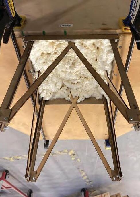
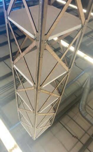
IBS I
[BREAK]
TOWER
PROJECT
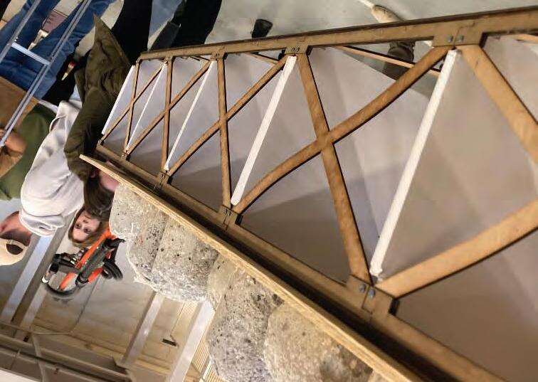
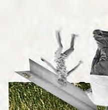
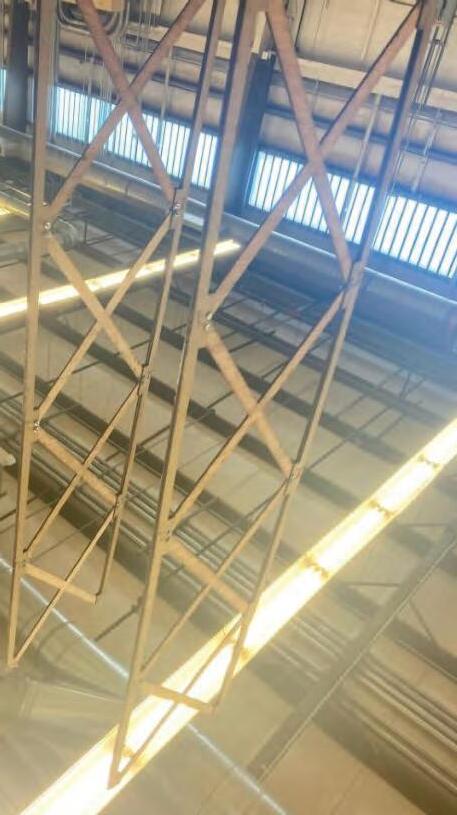
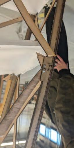
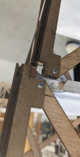
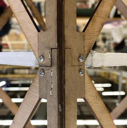
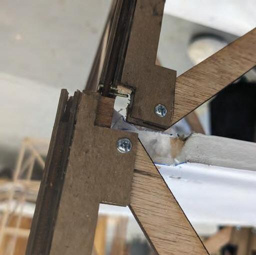
As part of the curriculum of shear forces on buildings, each team was assigned a force resisting system and tasked with withstanding force for as long as possible, until the inevitable... break.
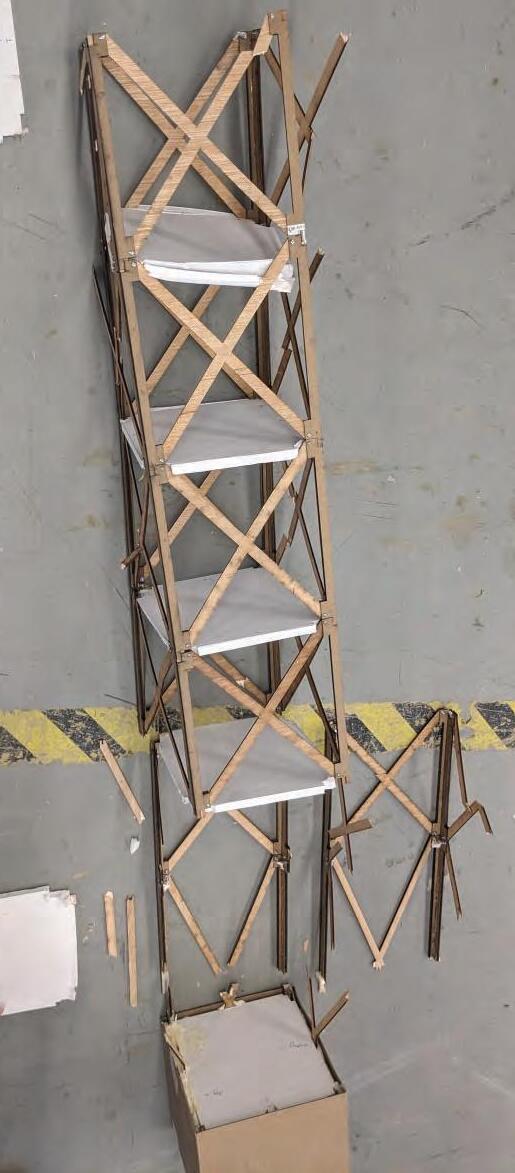
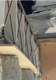
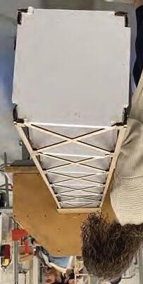
COMPOSITION


BEFORE AFTER
DESIGN STRATEGY; PANEL
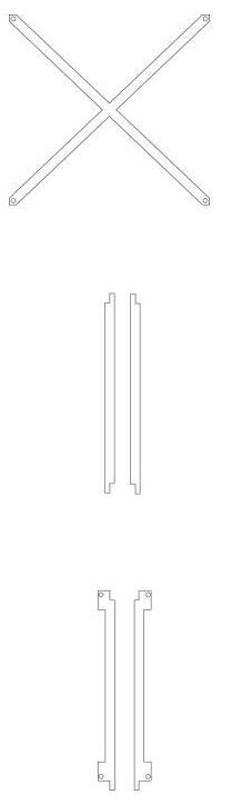
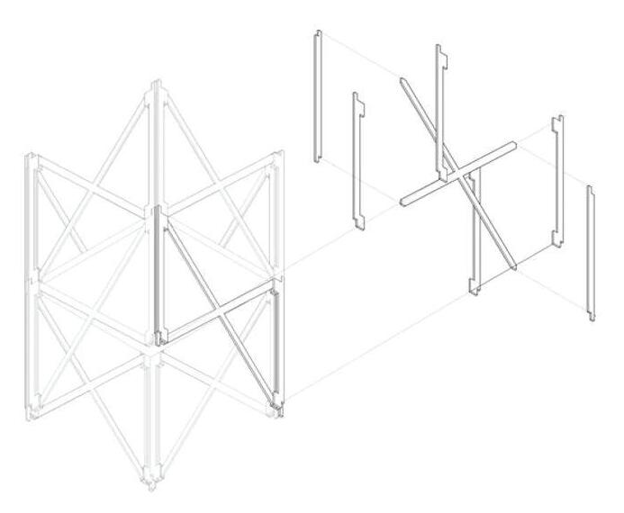
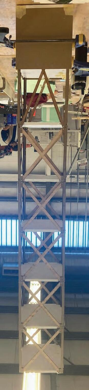
EXT. COLUMN - CHIPBOARD
INT. COLUMN - PLYWOOD
BRACE - PLYWOOD