1. INTRODUCTION
WLANHFSS
Revised Jul 10, 2022
Fractal antenna
Journal homepage: http://telkomnika.uad.ac.id
Vol. 20, No. 5, October 2022, pp. 963 970
ISSN: 1693 6930, DOI: 10.12928/TELKOMNIKA.v20i5 23489
Article Info ABSTRACT
In the past years, many researchers have done many researches on improving the bandwidth of the antenna for different applications. 5.8 GHz frequency is one of the most commonly used frequency and it have
Bandwidth enhanced deltoid leaf fractal antenna for 5.8 GHz WLAN applications
TELKOMNIKA Telecommunication Computing Electronics and Control
1Research Scholar, Department of Electronics and Communication Engineering, JNTU Anantapuram, India
Email: rudrama418.kodali@gmail.com
Article history:
Rani Rudrama Kodali1, Polepalli Siddaiah2, Mahendra Nanjappa Giri Prasad3
JNTU Anantapuram, India
A wideband deltoid leaf fractal antenna is proposed for 5.8 GHz commonly used in industrial scientific and medical (ISM) and wireless local area networks (WLAN) applications. A microstrip patch antennas is designed with leaf shape radiating element. Using a leaf shape, it is possible to increase the perimeter of a design and thus reduce the overall dimensions of the antenna. A circular ring slot is made on the leaf shaped radiator, in a way that a circular disc is loaded at centre. Triangular fractal slots are made inside the circular disc to make it miniaturized. A partial ground is maintained with slot at centre. The antenna is fed by micro strip feed. The locality and measurements of the fractal slots are varied to make the antenna radiate at 5.8 GHz with wider bandwidth (BW) of (2.26 GHz). The complete size of the antenna is 40 mm3 × 40 mm3 × 1.6 mm3. The step by step implementation of the antenna and the effects of its dimensions are compared and presented using the reflection coefficient curve. The measured reflections coefficient |S11|< 10 dB maintained the operational band from (5.36 GHz 7.62 GHz), with gain 4.2 dBi. The proposed antenna is planned and simulated using high frequency structure simulator (HFSS). The simulated and measured comparison showed good agreement, the designed antenna is suitable for 5.8 GHz WLAN applications with wider bandwidth requirements.
Corresponding Author: Rani Rudrama Kodali Research Scholar, Department of Electronics and Communication Engineering
Nowadays, wireless communication systems capable of serving wider band frequency coverage garnered much attention. These wireless communications systems require, antennas that provide enough wider coverage in terms of frequency range, while maintaining the low profile, low weight and compact size. Fractal models and loop models are frequently used to attain the miniaturization of the antenna. Fractal models are introduced to create different kinds of innovative designs to achieve multiple advantages in antenna size and performances [1]. Several kinds of fractal models have been introduced over the years to achieve antenna miniaturization [2] [4]. These fractals can be similarly positioned, could have decremental iterations or similar iterations to achieve the miniaturization of the antenna.
Accepted Jul 18, 2022
Deltoid leaf antenna
Band width enhancement

3JNT University College of Engineering, Anantapur, India
Keywords:
Received Mar 03, 2022
2AN University College of Engineering and Technology, ANU, Gunturu, India
This is an open access article under the CC BY SA license.
963
964good
TELKOMNIKA Telecommun Comput El Control, Vol. 20, No. 5, October 2022: 963 970
ISSN: 1693 6930
Fractal based models also helps in achieving the wideband antennas. In recent times several fractal antennas are designed with wider bandwidth, some ultra wide band antennas width band rejection characteristics or with enhanced ultra wide band (UWB) coverage are designed using fractal geometry designs. While incorporating the fractal models the selection of the radiator play vital role in achieving the wider bandwidth ratio easily [9]. Square shaped fractal model is used as metamaterial loaded antenna to achieve the bandwidth (BW) enhancement in [10]. Fractal antenna model along with meander line transmission line is used to achieve wider bandwidth for L band applications in [11]. Cylindrical shaped DRA’s are used to position them as fractal model to design wideband fractal antenna that covers from 2.6 GHz 4.34 GHz in [12]. In [13], Koch fractals are used as metasurface slots to designed wideband antenna that covers from 1.45 GHz 4.86 GHz. In [14], hexagonal fractal antenna with Koch is used to achieve the UWB coverage. Smiley shaped fractal model is used to design UWB antenna in [15]. Hexagonal shaped fractal geometry is used to design radiator and the defective ground surface is used along with the radiator to develop high gain wideband antenna [16].
2. ANTENNA CONFIGURATION
scope for improving the bandwidth to have wide range of coverage. Different approaches are utilised to enhance the bandwidth of antenna. Some of the commonly used methods are using slots, fractals and metamaterial inspired structures. In [5], sectoral based fractal model is used to develop wideband monopole antenna at 5.8 GHz. In [6] a dielectric resonator antenna (DRA), with two segments DRA model is used to design miniaturized antenna with enhanced bandwidth to operate at 5.8 GHZ wireless local area networks (WLAN) applications. L shaped antenna which operates at 5.8 GHz is designed, the parasitic elements are utilised to upgrade the bandwidth of the antenna [7]. Step impedance resonator (SIR) based periodic structures are etched onradiator and ground plane to achieve the multi band antenna to operate at 2.4 GHz / 5.2 GHz and 5.8 GHz [8].
2.1. Antenna model
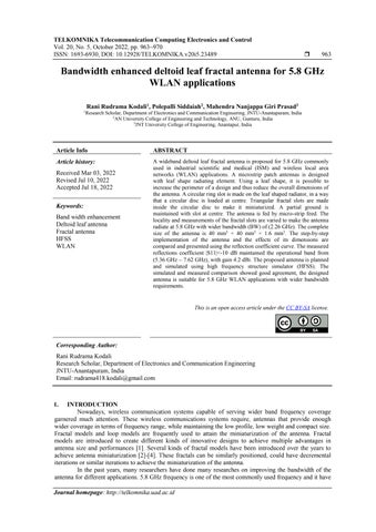
Figure 1 illustrates the proposed fractal antenna architecture. Antenna is designed based on leaf antenna model. It contains a circular ring slot and at centre triangular fractal slots are made. The fractals are followed as first a circular ring slot is made on the leaf radiator where its leaves a circular disc at centre. A triangular slot is made inside the circular disc. Another circular disc with less radius than the first iteration circular disc is made inside the triangular slot. The 2nd iteration circular disc is maintained in a it connects to the 1st iteration circular disc leaving three triangular shaped slots. Similarly, another triangular slot is made inside the 2nd circular disc to realize the ultimate model of the proposed antenna. FR 4 substrate with a relative permittivity of 4.4 and loss tangent of 0.02 of size 40 mm3× 40 mm3 × 1 6 mm3 is used as a substrate. The ultimate dimensions of the antenna shown in Figure1 after the parametric study are listed in the Table 1.
To improve the gain and wide impedance bandwidth properties of the antenna, hexagonal rings and triangular elements have been incorporated to create a fractal nature fed with a triangular slotted symmetrical defective ground structure with a rectangular slit at the center [17]. In [18] a printed monopole antenna with open mouth flower patch followed by a hard surface (HS) array provide an omni directional antenna along with the stability in the radiation pattern over the frequency band from 2.4 GHz to 10 GHz. A reconfigurable meta surface layers enhances the gain of microstrip antennas, PIN diodes are used to reconfigure the antenna structure, and a meta surface pattern of layers suggested to increase its gain [19]. By incorporating geometry of radiating patch dependent on the Sierpinski triangle fractal of a copper triangular layer, it was possible to achieve excellent reduction in mutual coupling among the antenna elements of a monopole antenna array for the multiple input multiple output (MIMO) applications [20]. In [21] an inverted lambda (��) shaped diploe attached to printed reflector and an inverted L ground plane of a microstrip patch anteena is used to realize a bandwidth enhancement. As a result of the reflector structure, a frequency resonance occurs at 1.1 GHz, 2.5 GHz and other band from 3.5 GHz to 6 GHz. The split ring resonators (SRR) array improved the antenna matching and tuned to the frequency range 3 GHz up to 7.45 GHz and a complete boresight gain around 7 dBi over that frequency band. An electromagnatic band gap lens is in corporated into circular truncated slotted square patch antennas to enhance antenna gain, bandwidth, impedance matching, and resonance frequency [22]. In [23] a castor leaf shaped quasi self complementary antenna with double band rejection characteristics is presented for the broadband applications. The fractal based star shaped antenna design with a wide operating bandwidth can be effective for S band applications [24]. In [25] a bio inspired linden leaf shaped antenna between the operating frequency 1.6 GHz and 2.6 GHz for energy harvesting.
In this paper, leaf model antenna is considered due to its capabilities of achieving wider bandwidth. Circular ring along with triangular shaped fractals are etched in patch element to achieve the wideband fractal antenna which operates at 5.8 GHz. The designed antenna covers from 5.36 GHz to 7.62 GHz. Tuning the dimensions of the fractal slots helped in achieving the required frequency of operation and enhanced BW. The fabricated antenna showed good agreement in reflection coefficient comparison with simulated data. It maintained gain 4.2 dBi at operating frequency 5.8 GHz.
enhanced deltoid leaf fractal antenna for 5.8 GHz WLAN applications (Rani


Figure 3. Reflection coefficient comparison of the antenna design steps
965 (a) (b) (c) Figure1 Proposed antenna model: (a) top view, (b) fractal part enhanced view, and (c) back view Table 1 The measurements of the proposed fractal antenna Parameter Value (mm) Parameter Value (mm) Parameter Value (mm) Parameter Value (mm) �� 40 ��1 10 ���� 1 ���� 13.8 ��1 18.455 ��2 7.211 ���� 13.0722 ������ 1 ��2 8.66 ��3 6 ���� 2.4 ������ 2.8 ��3 3.464 ��4 3
Figure 2 Step by Step evolution of wider band fractal antenna
The proposed antenna is fed by the centre positioned microstrip feed line. The antenna performance comparison for the step by step evaluation is presented using the reflection coefficient (��11) vs frequency curve is presented in the following Figure 3. For the step 1 and 2 reflection curve showed poor impedance

TELKOMNIKA Telecommun Comput El Control
The step by step design procedure of the fractal antenna is presented in the Figure 2. In step 1 a leaf model is taken as radiator. In step 2, a circular slot is made at centre. In step 3, another circular disc is placed at centre with less radius than the, circular slot made in step 2. In step 4, a triangular slot is made inside the circular disc positioned at centre in step 3. In step 5 another circular disc with triangular slot is added at centre.

Bandwidth Rudrama Kodali)
2.2. Antenna analysis
966matching
2.4. Simulated analysis
ISSN: 1693 6930
TELKOMNIKA Telecommun Comput El Control, Vol. 20, No. 5, October 2022: 963 970
In order to highlight the usage of the slots to achieve the better performance of the antenna. The antenna performance is compared in the Figure 5 for the original leaf model and the proposed model. From Figure 5 it can be clearly seen that the leaf model at base step with the same dimensions operates at 6 GHz with return loss 20 dB and maintained operation band below 10 dB from 5.5 GHz to 7.5 GHz. For the proposed design after the slots are made it operated at 5.8 GHz with return loss 30 dB and maintained operational band below 10 dB from 5.4 GHz to 7.7 GHz.
2.3. Parameter study
and less operation band and the frequency of operation is away from the intended 5.8 GHz frequency. For steps 3 to 5 the operation bandwidth is almost maintained similar, but when compared for step 5 the operation band is maintained higher and also the operating frequency is at 5.8 GHz. Step 5 is more miniaturized and achieved higher band width with required operating frequency 5.8 GHz.
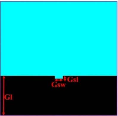
In order to get the optimal antenna measurements and also the parameters of the lead antenna, leaf side triangle edge length (��1), first circular slot radius (��2) are varied, analysed and the comparative analysis is shown in the following Figure 4 using ��11 vs frequency curves. From Figure 4(a) it can be seen that, when ��1 dimension is increasing the reflection coefficient response shifting towards the lower resonance and the impedance matching is getting poorer, after the parametric study at ��1 = 18.45 mm, the proposed antenna is maintaining the intended frequency of operation at 5.8 GHz with good impedance matching. From Figure 4(b) it can be observed that, similar to t1 when ��2 is increased the operating frequency is shifting towards the lower resonance, at ��2 = 7.211 mm it maintained the intended operating frequency 5.8 GHz. Similarly other antenna dimensions are also tuned and the optimal values after the parametric study are listed in the Table1.
Figure 5 Reflection coefficient comparison between the basic leaf model and the proposed fractal model
Figure 4 Parametric study comparison using reflection coeffcient for (a) dimension ��1 and (b) dimension ��2

(a) (b)

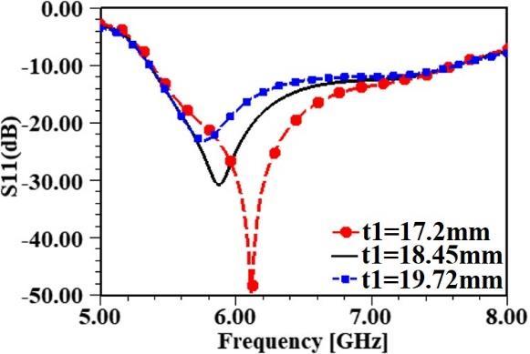
Figure7. 3D radiation plots: (a) basic leaf model and (b) proposed fractal model

3. RESULTS AND DISCUSSION
Telecommun
TELKOMNIKA Comput
El Control
Bandwidth enhanced deltoid leaf fractal antenna for 5.8 GHz WLAN applications (Rani Rudrama Kodali)


Similarly, in Figure 6(a) compares the reflection coefficient of the antenna design steps and Figure 6(b) presents comparision interms of axial ratio. Figure 7(a) and Figure 7(b) represents 3D radiation plots compared and presented for leaf model and the proposed fractal model. From Figure 6(a) it can be observed that, the current distribution is weak at center, where the slots are made as shown in Figure 1. This helped in altering the current distribution and achieving the miniaturized fractal antenna with enhanced bandwidth. From Figure 7 it can be seen that, the leaf antenna maintained utmost gain 5.2 dBi where as for the proposed fractal model the maximum gain is improved to 5.4 dBi.
(a) (b)
967
Figure 6. Surface current distribution: (a) basic leaf model and (b) proposed fractal model
(a) (b)
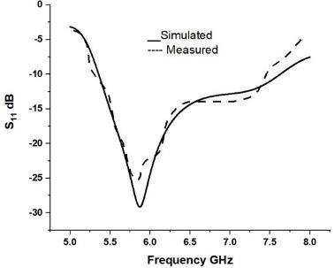
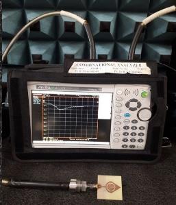
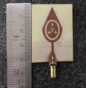
According to the dimensions listed in Table 1, the fractal antenna is successfully designed and measured. The fractal antenna fabricated prototype model is presented in the Figure 8(a). The �� parameters measurement setup inside the anechoic chamber is illustrated in the Figure 8(b). Figure 9(a) shows the simulated and measured comparison for the ��11 and Figure 9(b) shows VSWR comparison. The comparison showed that, the fractal antenna maintained quality agreement between the simulated and the measured analysis. The slight deviation could be caused by the unavoidable fabrication issues.
Figure 8. Proposed fractal antenna: (a) prototype and (b) ��11 measurement setup
Figure 11. 2D radiation patterns: (a) E plane radiation pattern of the fractal antenna at 5.8 GHz and (b) H plane radiation pattern
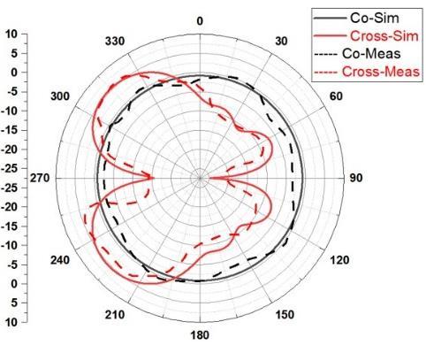
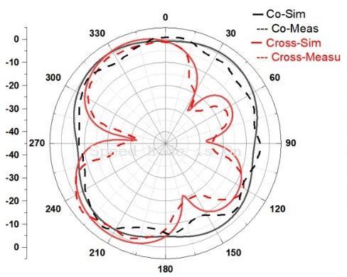
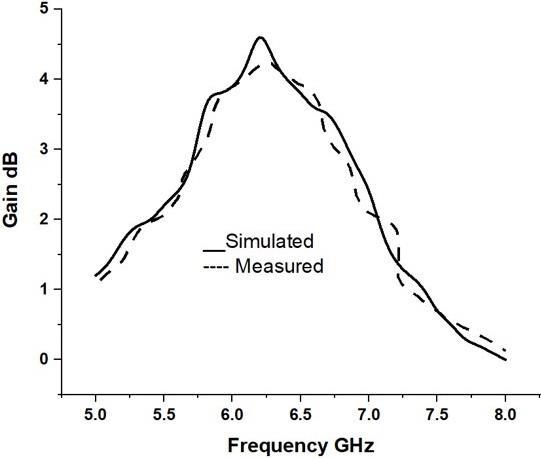
Figure 10. Simulated and measured comparison for gain vs frequency
TELKOMNIKA Telecommun Comput El Control, Vol. 20, No. 5, October 2022: 963 970 968
Figure 9. Simulated and measured comparative analysis: (a) ��11vs Frequency and (b) VSWR
(a) (b)
Similarly, the simulated and measured comparison of the gain vs frequency curve is presented in the following Figure 10. It can be seen that the antenna gain measurement maintained as per expectations in the intended operation band. The proposed antenna radiation pattern comparison for simulated and measured in e plane and h plane for the co and cross polarization are illustrated in the following Figure 11. The patterns maintained mostly omni shape at 5.8 GHz. For the better understanding of working performance of the designed antenna, comparison with previous existing models is listed in the following Table 2.

(a) (b) (a) (b)
ISSN: 1693 6930
[8] C. Feng, Y. Kang, L. Dong, and L. Wong, “High Gain SIR Dual Band Antenna Based on CSRR Enhanced SIW for 2.4/5.2/5.8GHz WLAN,” International Journal of Antennas and Propagation, pp 1 10, 2020, doi: 10.1155/2020/8725192
[1] D. H. Werner, R. L. Haupt, and P. L. Werner, “Fractal antenna engineering: The theory and design of fractalantennas arrays,” IEEE Antennas and Propagation Magazine, vol. 41, no. 5, pp. 37 58, Oct. 1999, doi: 10.1109/74.801513
[2] C. P. Baliarda, J. Romeu, and A. Cardama, “The Koch monopole: A smallfractal antenna,” IEEE Transactions on Antennas and Propagation, vol. 48, no. 11, pp. 1773 1781, Nov. 2020, doi: 10.1109/8.900236
This paper presents, a compact wideband fractal antenna is designed and presented for 5.8 GHz WLAN applications. The design is based on leaf radiator. A circular ring along with triangular fractal slots are made to achieve the wideband with frequency of operation at 5.8 GHz. The ground of this antenna is maintained partial with slot at centre to improve band width further. The antenna maintained the return loss below 10 dB from 5.36 GHz to 7.62 GHz maintaining bandwidth of 2.26 GHz. The fabricated prototypes showed good agreement with simulated data when measured. The designed antenna maintained gain around 4.2 dBi at 5.8 GHz. The proposed wideband antenna is good for 5.8 GHz WLAN applications Leaf designed microstrip patch antenna layout technique is used for the further improvent of the engineered antennas for the wireless communication applications.
Table 2. Performance comparison between the proposed antenna and previous work Antenna design Operating frequency (GHz) Dimensions (mm) Band width (GHz) Gain (dBi) Proposed work 5.8 40×40×1.6 5.36 7.62 4.2
ACKNOWLEDGEMENTS
[6] K. K. Gebril, S K B A Rahim, and A Y Abdulrahman, “Bandwidth Enhancement and Miniaturization of Dielectric Resonator Antenna for 5.8 GHz WLAN,” Progress In Electromagnetics Research C, vol. 19, pp. 179 189, 2011, doi: 10.2528/PIERC10121203.
TELKOMNIKA Telecommun Comput El Control
[10] P. Mishra, S. S. Pattnaik, and B. S. Dhaliwal, “Square Shaped Fractal Antenna Under Metamaterial Loaded Condition for Bandwidth Enhancement,” Progress in Electromagnetics Research C, vol. 78, pp. 183 192, 2017, doi: 10.2528/PIERC17082701
[15] M Susila, T R Rao, and A Gupta, “A Novel Smiley Fractal Antenna (SFA) Design and Development for UWB Wireless Applications,” Progress in Electromagnetics Research C, vol. 54, pp. 171 178, 2014, doi: 10.2528/PIERC14091803
[6] 5.8 30×40×0.8 5.5 6.2
4. CONCLUSION
[17] N. K. Darimireddy, R. R. Reddy and A. M. Prasad, “A Miniaturized Hexagonal Triangular Fractal Antenna for Wide Band Applications [Antenna Applications Corner],” in IEEE Antennas and Propagation Magazine, vol. 60, no. 2, pp. 104 110, 2018, doi: 10.1109/MAP.2018.2796441.
[7] 5.8 50×50×1 5.7 6.08
REFERENCES
[12] K Gangwar, A Sharma, G Das, and R K. Gangwar, “Investigation on novel wideband fractal antenna design based on cylindrical shape dielectric resonator,” International Journal of RF and Microwave Computer Aided Engineering, vol. 29, no. 11, 2019, doi: 10.1002/mmce.21943
969
[9] M. A. Matin, Ultra Wideband Current Status and Future Trends, INTECH, 2012, doi: 10.5772/2588
[14] M. Gupta and V. Mathur, “Hexagonal Fractal Antenna using Koch for Wireless Applications,” Frequenz, vol. 72, no. 9 10, pp. 443 453, 2018, doi: 10.1515/freq 2017 0203.
[3] H. Oraizi, S. Hedayati, “Miniaturized UWB monopole microstrip antenna design by the combination of Giusepe peano and Sierpinski carpet fractals,” IEEE Antennas and Wireless Propagation Letters, vol. 10, pp. 67 70, 2011, doi: 10.1109/LAWP.2011.2109030
[5] 6.15 27×35×1.6 3.22 6.55 4.35
[7] L. Peng, Y. J. Qiu, L Y. Luo, and X. Jiang, “Bandwidth Enhanced L Shaped Patch Antenna with Parasitic Element for 5.8 GHz,” Wireless Personal Communications, vol. 91, pp. 1163 1170 2016, doi: 10.1007/s11277 016 3519 y
[13] G. Liu, J. Gu, Z. Gao, and M. Xu, “Wideband printed slot antenna using Koch fractal metasurface structure,” International Journal of RF and Microwave Computer Aided Engineering, vol. 30, no. 3, 2020, doi: 10.1002/mmce.22058
[16] A. Desai, T. K. Upadhyaya, R. Patel, S. Bhatt, and P. Mankodi, “Wideband High Gain Fractal Antenna for Wireless Applications,” Progress in Electromagnetics Research Letters, vol. 74, pp. 125 130, 2018, doi: 10.2528/PIERL18011504.
[4] F. Wang, F. Bin, Q. Sun, J. Fan, and H. Ye, “A compact UHF antenna based on complementary fractal technique,” IEEE Access, vol. 5, pp. 21118 21125, 2017, doi: 10.1109/ACCESS.2017.2756672
[18] T A. Elwi, O A Tawfeeq, and Y Alnaiemy, H. S. Ahmed, and N. Lajos, “A UWB Monopole Antenna Design based RF Energy Harvesting Technology,” 2018 Third Scientific Conference of Electrical Engineering (SCEE), 2018, pp. 111 115, doi: 10.1109/SCEE.2018.8684112
We would like to thank the Organization of Lakki Reddy Bali Reddy College of Engineering (Autonomous), Acharya Nagarjuna University, Guntur and JNTU University, Anantapuramu for support to use R&D Laboratories.
[5] Y. K. Choukiker and S. K. Behera, “Compact sectoral fractal planar monopole antenna for wideband wireless applications,” Microwave and Optical Technology Letters, vol. 56, no. 5, pp. 1073 1076, 2014, doi: 10.1002/mop.28272
[11] P H Mukti, S H Wibowo, and E. Setijadi, “A Compact Wideband Fractal Based Planar Antenna with Meandered Transmission Line For L Band Applications,” Progress in Electromagnetics Research C, vol. 61, 139 147, 2016, doi: 10.2528/PIERC15102302
Bandwidth enhanced deltoid leaf fractal antenna for 5.8 GHz WLAN applications (Rani Rudrama Kodali)
BIOGRAPHIES OF AUTHORS
Polepalli Siddaiah obtained B.Tech degree in Electronics and communication Engineering from JNTUA College of engineering, Andhra Pradesh, India in 1988. He received his M.Tech degree from SV University Tirupathi, Andhra Pradesh, India. He did his Ph.D program in JNTU Hyderabad, Andhra Pradesh, India. He is the Chief Investigator for several outstanding Projects sponsored by Defence Organizations, AICTE, UGC & ISRO. He is currently working as Professor and Principal, Department of ECE in University College of Engineering and Technology, Acharya Nagarjuna University, Guntur, India. He has taught a wide variety of courses for UG & PG students and guided several projects. Several members successfully completed their Ph.D under his guidance. Several members pursuing their Ph.D degree. He has published several papers in National and International Journals and Conferences. He is the life member of FIETE, IE & MISTE. He can be contacted at email: siddaiah_p@yahoo.com
[19] H Almizan, Z. A. A. Hassain, T A. Elwi, and S. M. Al Sabti, “Controlling Gain Enhancement Using a Reconfigurable Metasurface Layer,” 2021 12th International Symposium on Advanced Topics in Electrical Engineering (ATEE), 2021, pp. 1 6, doi: 10.1109/ATEE52255.2021.9425037.
970
[21] T A. Elwi, L W. Rasheed, M A. K. Anber, and M. Q. Fahad, “Gain Enhancement of a Miniaturized Inverted λ Dipole Antenna,” ICICT '19: Proceedings of the International Conference on Information and Communication Technology, 2019, pp. 7 11, doi: 10.1145/3321289.3321291
[20] Z AL Dulaimi, T A. Elwi, D C Atilla, and C Aydin, “Design of Fractal Based Monopole Antenna Array with Ultra Mutual Coupling Reduction for MIMO Applications,” 2018 18th Mediterranean Microwave Symposium (MMS), 2018, pp. 39 42, doi: 10.1109/MMS.2018.8611858
[25] K Çelik and E. Kurt, “Design and implementation of a dual band bioinspired leaf rectenna for RF energy harvesting Applications,” InternationalJournalofRFand MicrowaveComputer Aided Engineering, vol. 31, no. 11, 2021, doi: 10.1002/mmce.22868

[24] S. Pandav, T. K. Das, K. R. Samyuktha, S. K. Behera, G. Sadhukhan, and M. Mohanty, “Design of Star Shaped Fractal Antenna for Wideband Applications,” 2020 IEEE International Students’ Conference on Electrical, Electronics and Computer Science (SCEECS), 2020, pp. 1 4, doi: 10.1109/SCEECS48394.2020.140
[22] S. R. Patre and S. P. Singh, “Castor leaf shaped quasi self complementary antenna with dual band rejection characteristics,” 2015 IEEE Applied Electromagnetics Conference (AEMC), 2015, pp. 1 2, doi: 10.1109/AEMC.2015.7509204
ISSN: 1693 6930 Telecommun Comput El Control, Vol. 20, No. 5, October 2022: 963 970

Rani Rudrama Kodali obtained her B.Tech degree in Electronics and communication Engineering from Acharya Nagarjuna University, Guntur, India in 1992. She received her M.Tech degree from J N T U Hyderabad, Andhra Pradesh, India in 2007. She is presently pursuing Ph.D degree in Electronics and communication Engineering, in the field Microstrip patch Antennas from JNTU Anantapur,Anantapur, India. Presently she is working as a Asst. professor in Electronics and Communication Engineering Dept, Lakireddy Bali Reddy College of Engineering, Mylavaram, AndhraPradesh, India. She is the life member of IETE, member of ISTE. She can be contacted at email: rudrama418.kodali@gmail.com
Mahendra Nanjappa Giri Prasad received his B.Tech degree from J.N.T University college of Engineering, Anantapur, Andhra Pradesh, India in 1982. M.Tech degree from S.V. University, Tirupati, Andhra Pradesh, India in 1994 and Ph.D degree from J.N.T. University, Hyderabad, Andhra Pradesh, India in 2003. Presently he is working as a professor in Electronics and Communication Engineering Dept. at J.N.T University college of Engineering, Anantapur, Andhra Pradesh, India. His research areas are Digital Signal Processing, Digital Image Processing, Bio Medical Signal Processing, Wireless Communication and VHDL coding. He has more than 50 publications in the standard international/Technical journals and more than 30 National/International Conferences. Several members successfully completed their Ph.D under his guidance. Several members pursuing their Ph.D degree. He is Life member of ISTE, IE and NAFEN He can be contacted at email: Mahendragiri1960@gmail.com


[23] X. P. Li, G. Xu, M. R. Ma, and C. J. Duan, “UWB Dual Band Notched Lanky Leaf Shaped Antenna with Loaded Half Square Like Slots for Communication System,” Electronics, vol. 10, no. 16, 2021, doi: 10.3390/electronics10161991.
TELKOMNIKA