This is an open access article under the CC BY SA license.
PEM fuel cell
Article history:
StationaryPEMFC applications
A proton-exchange membrane fuel cell and ultra-capacitor system model for stand-alone residential applications
Corresponding Author: Ibrahim ElectricalAlhamrouniEngineering
Energy consumption by sector in Malaysia is rising significantly, especially for residential and commercial sectors, and is expected to continue to increase in the upcoming years. The existing power generated from a proton exchange membrane fuel cell (PEMFC) system may be insufficient to sustain peak load demands during peak periods in stationary residential applications. The presence of an ultra capacitor (UC) bank would be beneficial as a support as it can supply a large burst of power. The integration of PEMFC and UC has the potential to provide an effective way to supply power demands, has better energy efficiency, and is also economically friendly. In this research, we demonstrate a proposed combined PEMFC and UC bank that operates in parallel. A novel design methodology and dynamic model for both PEMFC and UC systems as energy sources have been developed for stand alone residential applications. The simulation results are shown in Matlab Simulink. These results are based on mathematical and dynamic models of the system being shown.
Revised Jul 24, 2022
Section, British Malaysian Institute, University Kuala Lumpur (UniKL BMI) Gombak 53100, Kuala Lumpur, Malaysia
Energy consumption per capita has been increasing steadily in Malaysia over the past 40 years (1973 2016), which is from 0.395 1.793 Mtoe/Millions, and it is expected to rise in the upcoming years [1], [2]. The increase in energy consumption is affected by high population growth and is stated based on [3], [4]. Malaysia’s current population is about 32 million. Aside from that, industry uses the most energy in Malaysia, followed by transportation, residential and commercial buildings, non energy uses, and agriculture.
2School of Electrical and Electronic Engineering, Universiti Sains Malaysia, Nibong Tebal, Penang, Malaysia
1Electrical Engineering Section, British Malaysian Institute, University Kuala Lumpur (UniKL BMI), Kuala Lumpur, Malaysia
Article Info ABSTRACT
Keywords: Energy demands

As for residential and commercial, the energy consumed by both sectors is rising, from 721 ktoe in the year 1978 to 8,729 ktoe in the year 2016. Hence, it shows that residential and commercial also consume a lot of energy as before and it will gradually increase as population growth is getting higher and housing areas are being developed rapidly in urban and rural areas, yet various solutions have been taken into consideration to overcome this issue [5], [6]. Due to the rise in demand for electricity, especially in urban areas, it is very important to have transmission networks that have the capability of delivering large amounts of electricity to consumers without encountering any problems [7], [8]. According to [9], [10], the estimation of demand depends on the load consumed by the client, in which case the information for the load profile aspect is owned by Tenaga Nasional Berhad (TNB) for different classes of consumers. The geographical location of Malaysia also affects the scope values of the demand profile to vary [11]. Table 1 shows the typical ranges of
Accepted Aug 01, 2022
1172
Journal homepage: http://telkomnika.uad.ac.id
3School of Electrical Engineering, Universiti Teknologi Malaysia, Skudai, Johor, Malaysia
Email: ibrahim.mohamed@unikl.edu.my
Energy efficiency
Ibrahim Alhamrouni1, Mohamed Salem2, Awang Jusoh3, Tole Sutikno4
TELKOMNIKA Telecommunication Computing Electronics and Control Vol. 20, No. 5, October 2022, pp. 1172~1180
Received Aug 06, 2021
4Department of Electrical Engineering, Faculty of Industrial Technology, Universitas Ahmad Dahlan, Yogyakarta, Indonesia
Ultra capacitor
1. INTRODUCTION
ISSN: 1693 6930, DOI: 10.12928/TELKOMNIKA.v20i5 24292
1 Low cost flats, single storey terrace, studio apartment (600 sq ft) 1.5 2 3
TELKOMNIKA Comput
Table 1. The range of maximum demand (M.D) for domestic consumer sub classes or premises [6] No Type of premise Rural (kW) Suburban (kW) Urban (kW)
3
Single storey bungalow and three room condominium 5 7 10
A parallel combination of polymer electrolyte fuel cells (PEFC) with supercapacitors has been proposed for the use of fuel cell vehicles (FCV) by [33]. This study aimed to facilitate the system of the fuel cell to work under peak power and to provide the brake energy system to recover. Supercapacitors are being used to combine with the PEFC in parallel without power electronic devices. This previous study showed that a parallel combination of the super capacitor (SC) and PEFC without electronic devices is possible and does not affect the consumption of fuel. Though it may seem reliable, the consumption will actually increase due
A proton exchange membrane fuel cell and ultra capacitor system model for… (Ibrahim Alhamrouni)
4
Single storey, semi detached 3 5 7
Telecommun
Double storey bungalow and luxury condominium 8 12 15
1173
El Control
Fuel cells are commonly referred to as electrochemical devices that convert chemical energy into electrical energy [15], [16]. Proton/polymer exchange membrane fuel cell (PEMFC) is considered to be one of the most promising fuel cells that can be applied these days because of its ability to deliver high power, high energy densities, and more efficient and clean energy [17]. Years after years, the demand for energy is getting higher, especially for residential areas. Much research and discovery are being conducted on how to manage this issue and provide solutions that will have a smaller global impact.
According to previous studies, the power generated by this type of fuel cell may not be sufficient to meet the load demand requirements, especially during peak demand periods. Thus, it will lead to an increase in size and also a rising cost of the fuel cell [18], [19]. Besides that, for residential applications, the capacities of gravimetric and volumetric requirements are rigid [20]. Hence, the ultra capacitor is used to be integrated with the fuel cell (FC) in parallel to support the existing stand alone system. Apart from that, the ultra capacitor (UC) bank that consists of several ultra capacitors plays a role in storing energy while producing outstanding outputs compared to other typical capacitors [21], [22]. Besides that, the UC bank is economically practical as the cost of this component is very low matched with its high capabilities compared to other types of cells in the usage for stand alone residential applications that might require a high demand for energy in peak periods.
2 Double storey terrace or apartment 3 4 5
5
6
A variety of techniques used for energy generation will be discussed with the presence of control strategies as they will contribute towards energy efficiency and peak power demands satisfactory for residential applications [23], [24]. For this work, proton exchange membrane fuel cells will be integrated with ultra capacitors (UC) or supercapacitors to supply the stand alone residential applications during non peak periods as well as during peak demand periods. The PEMFC system is a type of fuel cell that can generate electricity by operating reversely with the principle of PEM electrolysis. Fuel cells are energy devices with a fixed charge that convert chemical energy into electrical energy [25], [26]. The main part of the PEMFC is the polymer electrolyte membrane where ions and electron transfers are conducted and inhibited, respectively, from one electrode or catalyst layer to the other. Fuel oxidation will occur at the anode electrode layers while the reduction reaction takes place at the cathode. The electrical energy is created by consolidating oxygen (O2) as well as hydrogen (H2) [27], [28]. In the PEMFC, platinum is known as a metal with immense catalytic activity for both electrode responses [29]. The platinum catalyst acts to split the hydrogen molecule, while the splitting of the oxygen molecule is complicated as it will cause significant electricity losses. Hence, this catalyst (platinum) is considered the best alternative for this process.
An ultra capacitor (UK) or (UC), also described as a supercapacitor, is an electrochemical device that is known to have a high value of capacitance compared to other types of capacitors. It tends to be 100 times more efficient than any capacitor in terms of energy per unit volume as well as the ability to store energy [30]. These fascinating and most commonly used devices usually get the most attention in small application systems. For satisfying peak power requirements, capacitors with higher power capabilities are used [31]. Ultra capacitors have a greater life than the typical capacitor, which usually has only a few thousand cycles [32].
Double storey, semi detached 5 7 10
maximum demand, including the residential areas in Malaysia. One of the reasons that has been considered for using this type of energy source, which is the fuel cell, is the environmental concerns [12]. The current source that is widely used in generating electricity is fossil fuels. This fossil fuel will have negative impacts on the environment and the world. Besides that, the future availability of fossil fuels is getting lower, yet technological developments require a lot of energy demand [13]. Thus, fuel cells become more practical to take over this source in the way that it is eco friendly and assuring to be used to generate energy in the future [14].
1174tothe
Figure 1 Model of PEM fuel cell stack
There are three important elements for hydrogen molar flow, which are hydrogen input flow, hydrogen flow, and hydrogen output flow when the reaction takes place. At the same time, the pressure of the water partial as well as the oxygen partial can be achieved. The PEMFC system utilizes hydrogen as stated to power demand, and the reformer generates hydrogen repeatedly during operation as shown in Figure 1. During operational conditions, proportional integral (PI) control is used to supervise the hydrogen flow rate depending on the output power of the PEMFC system. To accomplish this feedback, the output of the FC current is seized to the input, transforming the hydrogen into molar form. Apart from that, by using a PI controller, the volume of hydrogen available from the reformer can be applied to control the methane flow rate. Meanwhile, PI controllers also have their own drawbacks, which are PI, sliding mode, and artificial neural network (ANN) based unified power flow controller (UPFC) control systems. All these controllers regulate the power perfectly when the power system is operating in a single operating mode. No one has checked to see if these controllers can handle any change in the way the power system works at different operating points.
ISSN: 1693 6930
heavy drivetrain. There are some other methods that have been applied in order to provide electrical power for different stand alone applications done by previous studies.
2.2. UC system model
All the techniques that will be used for the integration or combination of the PEMFC system and UC bank to be applied to stand alone residential appliances will be described and explained in this section. This part of the section will concentrate on designing and integrating both energy sources to supply and satisfy the load demands in a stand alone residential area inhabited by a family that has 3 adults and 4 children. The PEMFC is maintained to be the main source of the system to satisfy the load demands, yet a stand alone source is not enough to supply the power during peak periods. Hence, UC bank is chosen to assist the PEMFC to satisfy the peak loads during peak periods. Different UC banks would have different product specifications and also output. Thus, BMOD0165 P048 C01 UC Bank is being selected to supply the power during the peak demand period. The UC bank also acts as energy storage and can be charged or discharged by itself or even by the main source, which is the PEMFC.
2.1. Dynamic model of PEMFC
2. METHOD
The proposed work utilizes the ultra capacitor or supercapacitor as an alternative energy source to supply and sustain the extra load required during peak periods. This will guarantee continuous supply to consumers and help to reduce the cost of electricity during peak hours and maximum demand. Figure 2 shows the model of the supercapacitor that is being designed using Matlab Simulink with all the expected
TELKOMNIKA Telecommun Comput El Control, Vol. 20, No. 5, October 2022: 1172 1180

Figure 2. Model of supercapacitor
No Parameter Specification
1175
TELKOMNIKA Telecommun Comput El Control
parameters. The model is designed based on parameters that are similar to the ultra capacitor from Maxwell Technologies, which is BMOD0165 P048 C01. This supercapacitor has 18 series capacitors, and the rated capacitance of each capacitor is 165 F. The product specifications details are shown in Table 2.
11
To supply effective specific energy for a prescribed load, diversified configurations of UC banks can be used. In practical applications, the desired amount of terminal voltage, electrical energy, as well as the capacitance of the UC storage system can be constructed using various numbers of UCs in series and parallel connections as shown in Figure 3. The number of capacitors can be driven by the terminal voltage that must be connected in series, which is used to build a bank. Apart from that, the number of capacitors in parallel connection is influenced by the total capacitance. This figure also illustrates the example of how several UC units can be combined to form a UC bank that is sufficient for satisfying the peak load demand. In Matlab Simulink, an example of how the ultra capacitor or supercapacitor bank model can be set up has been made.
8 Capacitance of individual cell 3,000 F 9 Stored energy, individual cell 3 Wh 10 Number of cells 18 Minimum operating temperature 40 12 Maximum operating temperature 65
In this section, the integration between PEMFC and UC Bank will be presented to prove the compatibility of both systems to satisfy the stand alone residential loads. The integration of the UC system can be achieved either with the presence of a power electronic converter or without it through a parallel
2.3. Combined PEMFC and UC system
A proton exchange membrane fuel cell and ultra capacitor system model for… (Ibrahim Alhamrouni)
Table 2 Product specifications for BMOD0165 P048 C01 UC bank
1 Electrical BMOD0165 P048 C01 2 Rated capacitance 165 F
3 Minimum capacitance/maximum capacitance 165 F/200 F 4 Rated voltage 48 V 5 Absolute maximum voltage 51 V 6 Absolute maximum current 1,900 A 7 Leakage current at 25 5.2 mA
This section proves that PEMFC, which is the main source, can satisfy the baseload during non peak periods (7 kW). Despite this successful event, the power that has been generated by the PEMFC does not satisfy the peak load demands during peak periods. This is because, during peak periods, the power demand is
The total resistance between PEMFC and the UC bank will determine the power sharing within both systems. In a nutshell, here is a summary of the main management planning for the integrated system:
ISSN: 1693 6930
1176connection.
During non peak periods (< 8 kW), the PEMFC system supplies its maximum power until it reaches its limit, and the remaining extra power generated is used to charge the UC bank. The terminal voltage of overall load demands determines the state of charging or discharging of the ultra capacitor bank system.
In the PEMFC system, UC bank can supply short term power interruptions. The other benefit of the UC bank is that it keeps the system from charging too much or too little.
Figure 3. Example UCs in series and parallel connection Figure 4. Circuit diagram for overall system
TELKOMNIKA Telecommun Comput El Control, Vol. 20, No. 5, October 2022: 1172 1180
During peak periods (≥ 8 kW), when peak load demands are required, the PEMFC system produces the rated power again and discharges the UC bank to fulfill the remaining power that the PEMFC system cannot satisfy.
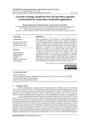
This section highlights the results that have been obtained from the analysis of data to attain and accomplish the objectives of this work. The PEMFC and ultra capacitor models used in this work have been designed and embedded in Matlab Simulink based on specific parameters. Apart from that, the model of the fuel cell is completed using the DC DC boost converter and PI/PID controller as the control strategies mentioned in the previous sections. In preparation for designing and completing the model of PEMFC as well as the ultra capacitor, all the parameters and characteristics of the model itself have been considered to ensure the ideal version of this research will be done successfully. Some of the research has been reviewed and discussed in the previous sections. So, the dynamic behavior of each element must be taken into account and shown to make sure that power flows as efficiently as possible.
UCunitUCunit UCunitUCunitUCunit UCunit UCunitUCunitUCunit UCbankvoltage ns np UCbankcurrent DCBUS PEMFC BMOD0165 P048 C01
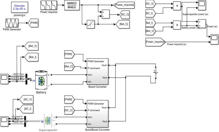
The simulation result obtained in Figure 5 shows the total amount of power that can be delivered to supply the stand alone residential applications during the non peak period. When non peak demands occur, the power required is only 7 kW, and this can be satisfied by using the stand alone PEMFC itself as the main source. This is because the PEMFC can generate power that varies from 7.008 kW and can reach up to a maximum value of power, which is 8.325 kW. Hence, the simulation successfully shows the PEMFC can withstand the load during non peak periods. The remaining extra power generated can be stored in a UC bank if it is not required by the load.
3. RESULTS AND DISCUSSION
Also, using both systems together could work with a DC bus with a voltage of less than 50 V for low voltageFigureapplications.4illustrates the direct integration of the PEMFC system with the UC bank by using a power diode. The reason for using the power diode is to obstruct reverse current flow from getting into the FC system. The stand alone residential applications, which are a state when energy demand is low and only a small amount of energy is needed, and b when energy demand is high and the load needs more energy than what the PEMFC can provide.
TELKOMNIKA
Telecommun Comput El Control
A proton exchange membrane fuel cell and ultra capacitor system model for… (Ibrahim Alhamrouni)
1177
high as it can reach up to 9.5 kW and is expected to increase to 10 kW. Since this is the case, ultra capacitors or supercapacitors can be used as a backup power source to provide the extra power needed during peak times. As illustrated in Figure 6, the supercapacitor is capable of generating additional power of about 2 kW. This power is used to support and also to provide additional energy towards the main source (PEMFC) to satisfy the peak load demands of the stand alone residential applications during the peak period. Since the PEMFC can’t get that energy, the supercapacitor will store the rest of the energy that isn’t being used to meet the demand.
Figure 7. Load profile of stand alone residential applications
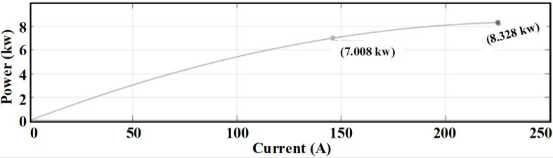
This section explains the load profile of the electrical system for a stand alone residential load that has been collected throughout a 24 hour period as shown in Figure 7. This section also introduces a software or application which has been used to gather all information and data about energy consumption before implementing the design of a combined PEMFC with UC bank to satisfy the load demands, especially during the peak periods, which are in need of extra power to be sustained. Most single family homes have a standard smart meter reader installed, which is used to track how much energy is used.
Figure 8 proves that the power generated by the combined PEMFC and UC bank is higher than the power required by the load during the 24 hour period. Each time the load demands a specific amount of power, the system will generate slightly more power to satisfy the load. When the load demand reaches peak periods, for example, during peak hours, the demand for energy will increase more than the limit of the

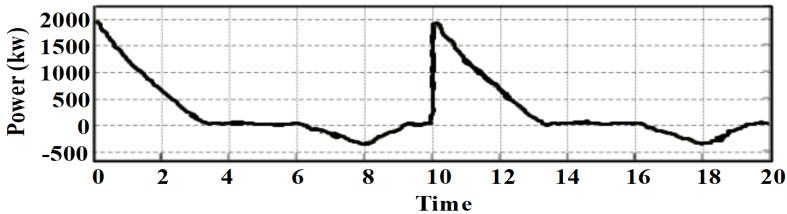
Figure 5. PEMFC power (kW)
Figure 6. Supercapacitor power (kW)
[2] U. Wethal, “Practices, provision and protest: Power outages in rural Norwegian households,” Energy Research and Social Science, vol. 62, 2020, doi: 10.1016/j.erss.2019.101388.
1178PEMFC
ACKNOWLEDGEMENTS
A combined PEMFC and ultra capacitor UC or supercapacitor bank was designed and modeled to meet the load demands of stand alone residential applications measured in kilowatts (kW) during non peak and peak times. The PEMFC and ultracapacitor were combined into parallel connections to ensure that electricity could be successfully delivered to residential load applications while also exhibiting good load performance. Without the availability of a UC bank, the PEMFC system must supply the additional power necessary during peak periods, which causes various issues such as an increase in the size and expense of the PEMFC system itself, as well as a reduction in system efficiency. The benefits of merging both PEMFC and UC bank sources can lengthen the lifespan of a PEMFC system rather than employing a stand alone FC system and lower maintenance costs. However, the proposed model can be applied for a variety of load profiles that include various transients and short term interruptions. It can also be employed in a variety of applications, including portable devices, heavy vehicles, and aerospace.

REFERENCES
profile real power and generated power from integrated PEMFC and UC bank
ISSN: 1693 6930
4. CONCLUSION
TELKOMNIKA Telecommun Comput El Control, Vol. 20, No. 5, October 2022: 1172 1180
[3] M. Amini, A. Khorsandi, B. Vahidi, S. H. Hosseinian, and A. Malakmahmoudi, “Optimal sizing of battery energy storage in a microgrid considering capacity degradation and replacement year,” Electric Power Systems Research, vol. 195, 2021, doi: 10.1016/j.epsr.2021.107170.
recommendations.Figure8.Load
The authors would like to express their gratitude to the following institutions for their support of this joint research project: the University of Kuala Lumpur (UniKL BMI), Universiti Sains Malaysia, Universiti Teknologi Malaysia, and Universitas Ahmad Dahlan.
would generate. This is where the UC bank will function to supply the remaining power required by the load. During this situation, the discharge current of the UC bank is at its peak and the terminal voltage of the system drops extremely. Thus, this system will switch to the UC bank beside the PEMFC when there is a shortage of power. Hence, it is a proof of success that the total power generated by the combined system satisfies the load of stand alone residential applications even during peak load demands. In addition, for improvement, distribution generation (DG) could be used as well in enhancing power transmission for this type of load, but it may not be necessary as DG systems are used for larger applications. DG is not only capable of solving most of the network’s expansion problems but also able to reduce power loss, enhance the reliability of the system, and improve the voltage level. DG also plays a big role in modern power systems since it is capable of reducing the line losses and improving the voltage level, which will significantly improve the power quality and efficiency of power transmitting and distributing from one point to another point. This system can also be implemented for larger stand alone residential areas for future
[1] Y. Zahraoui, I. Alhamrouni, S. Mekhilef, M. R. B Khan, B. P. Hayes, and M. Ahmed, “A novel approach for sizing battery storage system for enhancing resilience ability of a microgrid,” International Transaction Electrical Energy Systems, vol. 31, no. 12, 2021, doi: 10.1002/2050 7038.13142.
[11] W. Torki and M. Derbeli, “Modeling and control of a stand alone PEMFC for AC load PMSM application,” 2017 International ConferenceonGreenEnergyConversionSystems(GECS), 2017, pp. 1 6, doi: 10.1109/GECS.2017.8066208
A proton exchange membrane fuel cell and ultra capacitor system model for… (Ibrahim Alhamrouni)
[17] M. Papra, F. N. Büchi, and R. Kötz, “Investigating the Dynamics of a Direct Parallel Combination of Supercapacitors and Polymer Electrolyte Fuel Cells,” FuelCells, vol. 10, no. 5, pp. 873 878, 2010, doi: 10.1002/fuce.200900197
[21] S. Sharma, S. Bhattacharjee, and A. Bhattacharya, “Grey wolf optimisation for optimal sizing of battery energy storage device to minimise operation cost of microgrid,” IET Generation, Transmission and Distribution, vol. 10, no. 3, pp. 625 637, 2016, doi: 10.1049/iet gtd.2015.0429.
[23] S. Sukumar, H. Mokhlis, S. Mekhilef, K. Naidu, and M. Karimi, “Mix mode energy management strategy and battery sizing for economic operation of grid tied microgrid,” Energy, vol. 118, pp. 1322 1333, 2017, doi: 10.1016/j.energy.2016.11.018.
TELKOMNIKA Telecommun Comput El Control
[5] K. Gong, X. Wang, C. Jiang, M. Shahidehpour, X. Liu, and Z. Zhu, “Security Constrained Optimal Sizing and Siting of BESS in Hybrid AC/DC Microgrid Considering Post Contingency Corrective Rescheduling,” IEEE Transactions on Sustainable Energy, vol. 12, no. 4, pp. 2110 2122, 2021, doi: 10.1109/TSTE.2021.3080707.
[4] U. T. Salman, F. S. Al Ismail, and M. Khalid, “Optimal sizing of battery energy storage for grid connected and isolated wind penetrated microgrid,” IEEEAccess, vol. 8, pp. 91129 91138, 2020, doi: 10.1109/ACCESS.2020.2992654.
[8] K. Scott and A. K. Shukla, “Polymer electrolyte membrane fuel cells: Principles and advances,” Reviews in Environmental Scienceand Biotechnology, vol. 3, pp. 273 280, 2004, doi: 10.1007/s11157 004 6884 z
[13] J. Ramakrishnan and P. P. Vaidya, “Measurement of parameters of ultracapacitor,” 2017 2nd IEEE International Conference on Recent Trends in Electronics, Information & Communication Technology (RTEICT), 2017, pp. 1831 1835, doi: 10.1109/RTEICT.2017.8256915
1179
[33] D. Cerrai, M. Koukoula, P. Watson, and E. N. Anagnostou, “Outage prediction models for snow and ice storms,” Sustainable Energy, Gridsand Networks, vol. 21, 2020, doi: 10.1016/j.segan.2019.100294.
[10] P. J. R. Pinto, V. R. Fernandes, A. M. F. R. Pinto, and C. M. Rangel, “Analysis of a Stand Alone Residential PEMFC Power System with Sodium Borohydride as Hydrogen Source,” in 4th International Seminar on Advances in Hydrogen Energy Technologies: Oportunities and Challenges in a Hydrogen Economy, 2011, pp. 1 7. [Online]. Available: http://repositorio.lneg.pt/bitstream/10400.9/1470/1/AHET_FCM_%2032Pinto.pdf
[18] A. A. Hafez, A. Y. Abdelaziz, M. A. Hendy, and A. F. M. Ali, “Optimal sizing of off line microgrid via hybrid multi objective simulated annealing particle swarm optimizer,” Computers and Electrical Engineering, vol. 94, 2021, doi: 10.1016/j.compeleceng.2021.107294.
[29] C. Zhang, Y. L. Wei, P. F. Cao, and M. C. Lin, “Energy storage system: Current studies on batteries and power condition system,” RenewableandSustainableEnergyReviews, vol. 82, pp. 3091 3106, 2018, doi: 10.1016/j.rser.2017.10.030.
[30] B. K. Tan, N. M. L. Tan, and A. K. Ramasamy, “Design of a battery ultracapacitor hybrid energy storage system with power flow control for an electric vehicle,” International Journal of Power Electronics and Drive Systems, vol. 9, no. 1, pp. 286 296, 2018, doi: 10.11591/ijpeds.v9.i1.pp286 296
[32] I Alhamrouni, A Khairuddin, M. Salem, and A. Alnajjar, “Review on Transmission Expansion Planning Models,” Applied Mechanicsand Materials, vol 818, pp. 129 133, 2016, doi: 10.4028/www.scientific.net/AMM.818.129.
[19] S. A. P. Kani, P. Wild, and T. K. Saha, “Improving Predictability of Renewable Generation Through Optimal Battery Sizing,” in IEEE TransactionsonSustainable Energy, vol. 11, no. 1, pp. 37 47, 2020, doi: 10.1109/TSTE.2018.2883424
[20] I Alhamrouni, N. Zainuddin, M. Salem, N. H. A. Rahman, and L. Awalin, “Design of single phase inverter for photovoltaic application controlled with sinusoidal pulse width modulation,” Indonesian Journal of Electrical Engineering and Computer Science(IJEECS), vol. 15, no. 2, pp. 620 630, 2019, doi: 10.11591/ijeecs.v15.i2.pp620 630.
[9] L. Gao, Z. Jiang, R. A. Dougal, “An actively controlled fuel cell/battery hybrid to meet pulsed power demands,” JournalofPower Sources, vol. 130, no. 1 2, pp. 202 207, 2004, doi: 10.1016/j.jpowsour.2003.12.052
[24] P. Harsha and M. Dahleh, “Optimal management and sizing of energy storage under dynamic pricing for the efficient integration of renewable energy,” IEEE Transactions on Power Systems, vol. 30, no. 3, pp. 1164 1181, 2015, doi: 10.1109/TPWRS.2014.2344859.
[31] I. N. Moghaddam, B. H. Chowdhury, and S. Mohajeryami, “Predictive Operation and Optimal Sizing of Battery Energy Storage with High Wind Energy Penetration,” IEEE Transactions on Industrial Electronics, vol. 65, no. 8, pp. 6686 6695, 2018, doi: 10.1109/TIE.2017.2774732.
[16] S. D. L. Torre, J. M. G González, J. A. Aguado, and S. Martín, “Optimal battery sizing considering degradation for renewable energy integration,” IETRenewablePowerGeneration, vol. 13, no. 4, pp. 572 577, 2019, doi: 10.1049/iet rpg.2018.5489.
[15] A. Fathy, K. Kaaniche, and T. M. Alanazi, “Recent Approach Based Social Spider Optimizer for Optimal Sizing of Hybrid PV/Wind/Battery/Diesel Integrated Microgrid in Aljouf Region,” in IEEE Access, vol. 8, pp. 57630 57645, 2020, doi: 10.1109/ACCESS.2020.2982805
[14] Y. Ohki, “Commencement of operation of the world's largest storage battery facility [News from Japan],” in IEEE Electrical Insulation Magazine, vol. 33, no. 1, pp. 59 61, 2017, doi: 10.1109/MEI.2017.7804322
[7] H. R. Esmaeilian, R. Fadaeinedjad and G. Moschopoulos, “Dynamic operation and control of a stand alone PEM fuel cell system,” 2014 IEEE Applied Power Electronics Conference and Exposition APEC 2014, 2014, pp. 3378 3384, doi: 10.1109/APEC.2014.6803792
[12] I. Alhamrouni, M. Iskander, M. Salem, L. J. Awalin, A. Jusoh, and T. Sutikno, “Application of inductive coupling for wireless power transfer,” International Journal of Power Electronics and Drive Systems, vol. 11, no. 3, pp. 1109 1116, 2020, doi: 10.11591/ijpeds.v11.i3.pp1109 1116.
[25] M. Zolfaghari, N. Ghaffarzadeh, and A. J. Ardakani, “Optimal sizing of battery energy storage systems in off grid micro grids using convex optimization,” JournalEnergyStorage, vol. 23, pp. 44 56, 2019, doi: 10.1016/j.est.2019.02.027.
[22] Y. Zahraoui et al., “Energy Management System in Microgrids: A Comprehensive Review,” Sustainability, vol. 13, no. 19, 2021, doi: 10.3390/su131910492.
[27] B. Ismail, M. M. Naain, N. I. A. Wahab, L. J. Awalin, I. Alhamrouni, and M. F. A. Rahim, “Optimal placement of DSTATCOM in distribution network based on load flow and voltage stability indices studies,” 2017 International Conference on Engineering TechnologyandTechnopreneurship (ICE2T), 2017, pp. 1 6, doi: 10.1109/ICE2T.2017.8215973
[28] N. Mehmood and N. Arshad, “Towards Developing a Large Distributed Energy Storage using a Weighted Batteries Scheduling Scheme,” IEEEAccess, vol. 8, pp. 210733 210749, 2020, doi: 10.1109/access.2020.3039924.
[6] Tenaga Nasional Berhad, Electricity Supply Application Handbook, Third (3rd) Edition, Malaysia: Tenaga Nasional, 1949. [Online]. Available: https://www.tnb.com.my/assets/files/2022_ESAH_3.1.pdf
[26] L. Xu, X. Ruan, C. Mao, B. Zhang, and Y. Luo, “An improved optimal sizing method for wind solar battery hybrid power system,” IEEE TransactionsonSustainable Energy, vol. 4, no. 3, pp. 774 785, 2013, doi: 10.1109/TSTE.2012.2228509.
BIOGRAPHIES OF AUTHORS

Awang Jusoh was born in Terengganu, Malaysia in 1964. He received his B.Eng. degree from Brighton Poly technic, U.K., in 1988. He obtained his M.Sc. and Ph.D. degrees from the University of Birmingham, U.K., in 1995 and 2004, respectively. He is currently an Associate Professor in the Department of Power Engineering, Faculty of Electrical Engineering, Universiti Teknologi Malaysia (UTM), Johor, Malaysia. His research interests are in DC DC converters, renewable energy, and control of power electronics systems. He can be contacted at email: awang@fke.utm.my.
TELKOMNIKA Telecommun Comput El Control, Vol. 20, No. 5, October 2022: 1172 1180 1180
Tole Sutikno is a Lecturer in the Electrical Engineering Department at the Universitad Ahmad Dahlan (UAD), Yogyakarta, Indonesia. He received his B.Eng., M.Eng., and Ph.D. degrees in Electrical Engineering from Universitas Diponegoro, Universitas Gadjah Mada, and Universiti Teknologi Malaysia, in 1999, 2004, and 2016, respectively. He has been an Associate Professor at UAD, Yogyakarta, Indonesia since 2008. Since 2016, he has led the Embedded Systems and Power Electronics Research Group. His research interests include the fields of industrial applications, industrial electronics, industrial informatics, power electronics, motor drives, renewable energy, FPGA applications, embedded systems, image processing, artificial intelligence, intelligent control, digital design, and digital library. He can be contacted at email: tole@te.uad.ac.id.
Mohamed Salem received his B.Eng. in electrical and power engineering from Elmergib University, Libya, in 2008. In 2011, he received his M.Sc. in electrical engineering from (UTHM), Malaysia. In August 2017, he was awarded his Ph.D. degree by the Department of Power Engineering, Faculty of Electrical Engineering, Universiti Teknologi Malaysia. He is a member of IEEE and a registered graduate engineer (BEM) in the electrical track. Currently, he has been a senior lecturer at the School of Electrical and Electronic Engineering, Universiti Sains Malaysia, Penang, Malaysia since July 2018. He has authored and co authored a number of well recognized journals and conference papers. His research interests are in DC DC converters, renewable energy applications, and control of power electronic systems. He can be contacted at email: salemm@usm.my.
Ibrahim Alhamrouni received his B.Eng. degree in electrical engineering from Elmergib University, Al Khums, Libya, in 2008. I received my M.Sc. degree in electrical power engineering from Universiti Tun Hussein Onn Malaysia (UTHM), Batu Pahat, Johor, Malaysia, in 2011. In 2015, he was awarded his Ph.D. degree by the Faculty of Electrical Engineering, Universiti Teknologi Malaysia (UTM), Malaysia. Currently, he is a senior lecturer and researcher at the British Malaysian Institute, University of Kuala Lumpur, Malaysia. His research interests include power system planning and operation; deregulation and restructuring of power systems; and power line maintenance. He’s currently working on micro grid technologies and the application of power electronics in power systems. He can be contacted at email: ibrahim.mohamed@unikl.edu.my.

ISSN: 1693 6930

