TELKOMNIKA Telecommunication Computing Electronics and Control
Vol. 21, No. 4, August 2023, pp. 935~948
ISSN: 1693-6930, DOI: 10.12928/TELKOMNIKA.v21i4.24210
TELKOMNIKA Telecommunication Computing Electronics and Control
Vol. 21, No. 4, August 2023, pp. 935~948
ISSN: 1693-6930, DOI: 10.12928/TELKOMNIKA.v21i4.24210
Mhamed El Mrabet, Zineb Mekrini, Abdelilah El Mesbahi, Mohammed Boulaala
Industrial Systems Engineering and Energy Conversion Team, FSTT, Abdelmalek Essaadi University, Tétouan, Morocco
Article Info
Article history:
Received Jun 25, 2022
Revised Dec 07, 2022
Accepted Feb 16, 2023
Keywords:

3D printing
Brushless DC motor
PMSM
Stepper motor
3D printing is a process in which material is joined layer by layer under computer control to make a 3D object easy to get almost any shape. This technology finds applications in various fields and it is attracting considerable interest from industry and academia. There are many different brands and models of motors used in 3D printers, and they all vary in quality and effectiveness. In this article we present the principal of the 3D printer, types of motors used in 3D printer and mathematical modelling of this motors like brushless direct current (DC) motor, permanent magnet synchronous motor (PMSM), and stepper motor. The models of analytical equations describing the three systems of motors are evaluated and developed by Matlab/Simunlink. In this paper, we have conducted a comparison of the series of results from simulation between the performance of PMSM, brushless DC and stepper motor. Among several criteria, this simulation study allows to select the criterion of response time to reach the desired speed and the precision of the rotor position to choose the most performant motor for 3D printers.
This is an open access article under the CC BY-SA license.
Corresponding Author:
Mhamed El Mrabet
Industrial Systems Engineering and Energy Conversion Team, FSTT
Abdelmalek Essaadi University, Avenue Khenifra, Tétouan 93000, Morocco
Email: m.elmrabet@gmail.com
3D printing is a manufacturing process that uses the information from a PC and constructs the pieces layer by layer. This technique has caught much attention of the engineering and sciences [1]. It is a suitable method to meet the increasing demand by manufacturing complex parts with good quality [2]. There are different types of 3D printing classes. However, fused deposition modeling (FDM) is the dominant process. Used technology because of its simplicity and the very low cost of its materials [3]. Most of 3D printers use an open-loop stepper motor [4]. There are several types of electric motors that can provide the same displacement function in the direction of the three axes. That’s why we want to compare the performance of three types of motors, that are permanent synchronous magnet motor (PMSM), direct current (DC) brushless motor and stepper motor, to improve the quality of 3D printers However, in low-power applications such as 3D printers, electric induction motors (IMs) cannot be used due to their high weight-to-power ratio compared to the motors chosen for our study. Indeed, at equal power, the power density (kW/kg) of the induction machine is lower than that of the PMSM machine [5]. IMs are frequently not taken en consideration due to their limited power density and their lower efficiency [6]. Another disadvantage of IM is the losses in the rotor [5]. Indeed, the implementation of the induction motor in 3D printers is not adequate.
Most people are familiar with the various technologies related to these motors. PMSM have grown considerably in recent years [7]. These machines are perfectly designed for precise positioning, as they have
Journal homepage: http://telkomnika.uad.ac.id
feedback on the position, but they remain the most expensive solution [8]. The brushless DC (BLDC) machines are commonly used for high-speed applications [8], while stepper motors have the particularity that they can be moved at a desired interval and maintain this position [9]. Since they are an excellent motor for moving an object to a repetitive position, they are commonly used in the printers and robotics [10].
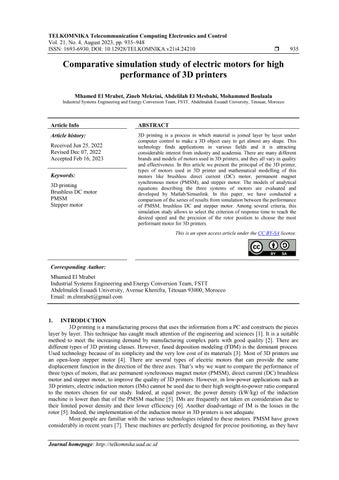
The operation of a PMSM is based on the attraction between the rotor and the stator. In the case of a PMSM, there is an attraction between the stator and the rotor. The main characteristic of the PMSM is the existence of a permanent magnet on the rotor, which makes the use of brushes unnecessary. The operation of the PMSM is based on the fixed magnetic field of the rotor and the rotating magnetic field of the stator [11]. Permanent magnets are employed as the rotor to generate a constant magnetic flux, to work and to be locked at the synchronous speed. In PMSMs, the torque ripple is due to the stator slot air gap and the non-sinusoidal flux density distribution around the air gap, which provides a variable magnetic reluctance function [12]. These kinds of motors are analogous to brushless DC motors.
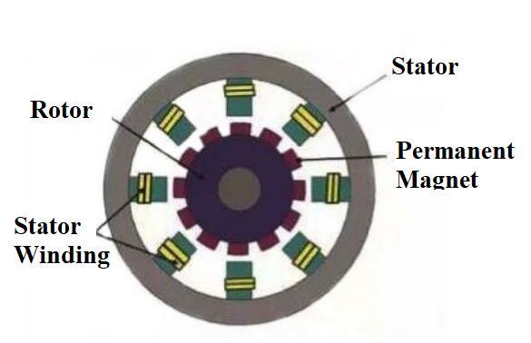
The design of the BLDC motor is given into two parts: a) the stator and b) the rotor. This kind of motor is made with different concepts such as the inner rotor and the outer rotor [13]. The BLDC motor is a brushless DC motor, without the need for a brush and collector for commutation, which has three-phase windings and is powered by a trapezoidal current wave to generate precise and powerful torque. The BLDC motor is defined as an internal and external DC motor becauseits magnets is located in the rotor and its armature in the stator [14].
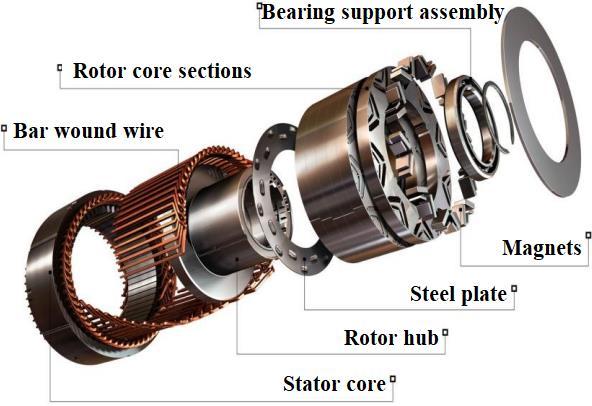
A stepper motor is an electrical motor that can be considered as an electric motor without a commutator. Its main characteristic is that its axis rotates in steps, which it moves by a defined number of degrees. In general, all motor windings are part of the stator, and the rotor is a permanent magnet. This characteristic also gives it a large variety of applications [15].
The stepper motor used in the 3D printer has a step loss problem. To solve this problem, the researchers replaced the stepper motor with a PMSM motor. The simulation performances of PMSM under closed-loop situation with stepper motor under both closed-loop and open-loop situation along are compared and analysed. Therefore, PMSM motor has the best performance for improving 3D printer [4].
This article discusses the differents type of motor such as the permanent magnet motor, BLDC and stepper motor to improve the characteristics of the 3D printer. The basic principles of the 3D printer and model of this machines will be presented as well as basic operation of each type of these machines and simulations result between the efficiency of PMSM, BLDC motor and stepper motor operate in 3D printing system. We will find that the PMSM have a great performance for improving 3D printer motor.
Performance of 3D printer can be expressed by 3 main criteria which do not have the same priority for everyone: a) the speed of printing, b) the aesthetic quality of the parts, and c) their dimensional quality. The purpose of this article is to test speed and acceleration. There are 4 main factors that are interesting for the choice of the electric motor: a) the parameters registered in the motor with the capacities of the printer, b) the mechanical limits, c) the power of the motors, and d) the available flow of the head for a given material. The accelerations of the motor, their speed, as well as the temperature of the nozzles are the important parameters for the high performance of the 3D printer.
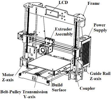
3D printing can easily manufacture complex geometry objects. Its flexibility is ensured by rapid design adjustments, which puts it in higher demand than subtractive manufacturing processes. Figure 1 presentes a typical design of FDM 3D printer. Principaly, this machine consists of a chassis that holds all the parts of the printer together and a build surface that moves along the linear �� axis and on which the object is printed. The print head (extruder) extrudes the filament and by moving along the linear �� and ��-axes. The three motors allow the movement in the three directions ��, ��, and ��. The role of motherboard is to control the motors according to the instructions sent by the computer and the signals from the sensors. Some time, a secure digital (SD) card, an universal serial bus (USB) port and/or an LCD user interface are present in the printer to allow input file of the part directly without using computer. The power supply unit is necessary to provide power for the operation of the 3D printer.
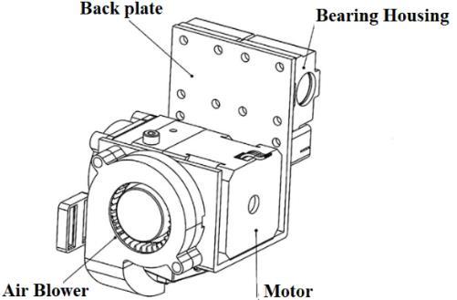
The main component of 3D printer is the extruder element. It is composed by a feeding mechanism (Figure 2) driven by electrical motor (Figure 3). The feeding system serves to supply plastic filament to the fusion chamber and to forced to pass through the extrusion orifice to guarantee the continuity of material flow at the end of extruder. The motor is assiciated with a gear mechanism to supply sufficient force to move the filament from the cold end to the hot end. The rotation of the motor is converted into linear movement of the filament with the help of a screw and nut mechanism. This mechanism is designed to be very precise, for this purpose, the choice of driving motor coupled to the driving-toothed wheel is essential.
3.1. Principal of the PMSM
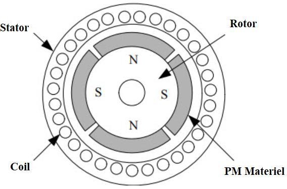
The permanent magnet synchronous motor is composed of a rotor and a stator. The rotor is usually located in the interior of the stator of the motor. Figure 4 shows an example of the PMSM motor construction [17]. The rotor is designed to create a number of magnetic poles equal or integral multiple of the number of stator poles. When the motor is energized, the rotor’s magnetic field clings to the stator’s magnetic field, and it turns at the same speed as the stator’s field. The slip value of the synchronous motor is zero. The speed of the motor depends on the number of stator poles and the supply frequency. The PMSM is composed of a coiled stator and a permanent magnet rotor, as shown in Figure 5. The magnetic field created by the permanent magnets of the rotor is constant. The principal of the permanent magnet synchronous motor is characterized by the reaction between the constant magnetic field of the rotor and the rotating magnetic field of the stator [12]. The creation of the rotating magnetic field of the PMSM is based on the same principle as that of the induction motor. The torque is given by the interaction between the magnetic fields of the stator and the rotor. The torque becomes maximum when the stator magnetic vector is perpendicular to the rotor magnetic vector.
This section will present the most used model of a PMSM, it is beneficial to write the equations to be solved in another way [18]. Therefore, the two-axis mathematical representation is used. The stator supply voltage consists of two essential parts: a) the voltage drop across the stator winding resistance and b) the fem induced by the flux variation.
Where ���� represents stator voltage in ����-coordinates, ����(��,��) represents stator flux linkage in ����-coordinates and ���� represents stator resistance. The resulting flux in the stator windings composed of two parts, the flux generated by the stator currents and the mutual flux created by the rotor field. So the total flux in the stator is expressed by (3), (4).
Comparative simulation study of electric motors for high performance of 3D printers (Mhamed El Mrabet)
Where ���� and ���� are the stator inductance, ���� is the magnitude of the flux from the rotor magnets and ����(��,��) is the stator current in (��,��)-coordinates [19]. The flux vector of the rotor rotates with the electrical speed and is displaced with the electrical angle from the ��-axis. Where ���� is the flux produced by permanent magnet. The mechanical modelling of PMSM motor (5), (6).
Where ���� is the electromagnetic torque, �� is the motor inertia and Ω is the mechanical speed. The coefficient of friction is �� and ���� is the resistant torque. ꙍ is the electric rotation speed and �� is number of pairs of poles.
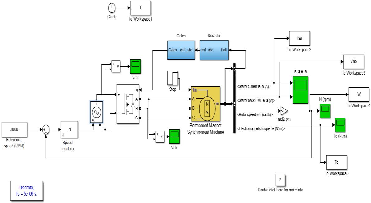
In Matlab/Simulink environment, using the module library in SimPowerSystem, we build a simulation model based on PMSM motor, which is shown in Figure 6 The PMSM block designs a permanent magnet synchronous motor with a three-phase star-wound stator. The current and speed loops are equipped with a PI controller to reduce the static error. The PMSM system principally consists of: PMSM model, pulse width modulation (PWM) converter model, ����2������ coordinate transformation model. We have chosen one of the most common type of electric motor used in 3D printer, with the following characteristics:
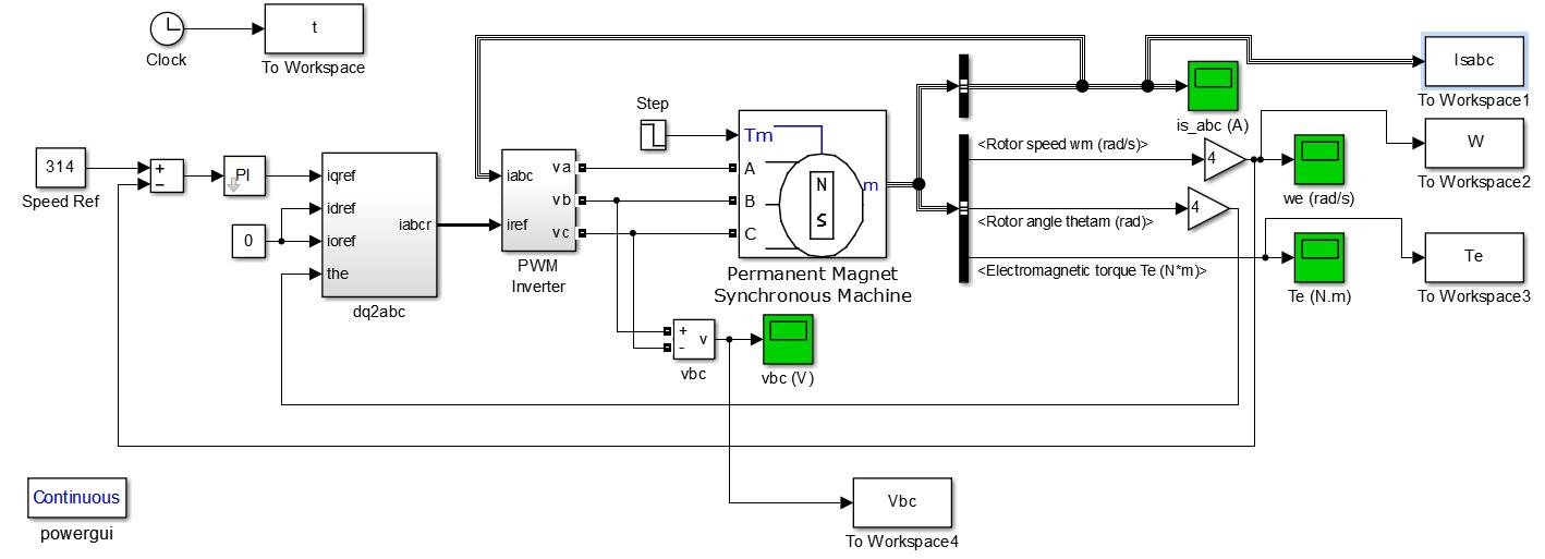
= 24 V, �� = 0.34 Ω, �� = 0.08 mH, �� = 8 10 6 kgm2 , �� = 0.18 Nm
3.4.
Figure 7 shows the shape of the three-phase current, when the motor is supplied with a constant torque. We adopted the transformation of park to simulate the current result, we have noticed that the current only becomes sinusoidal after a starting time. The torque generated by the motor is determined in Figure 8. At start-up the torque is too high, after which it becomes stable at a value of 0.2 Nm, which is adequate for moving the extruder and the build surface of 3D printer
The speed of the PMSM motor is given by Figure 9. We notice that the speed increases linearly at 6000 rpm after 0.8 ms, which improves the speed of 3D printing. The PMSM simulation model shows that the produced rotor angle will be used to have a sinusoidal current waveform to reduce the torque ripple. Figure 10 presents the form of the phase currents, voltages and the estimated rotor position using a reference model. The rotor angle initially at 0 increases to 1.8° in 0.3 ms, which improve the accuracy of 3D printing.
BLDC motors are built in different configurations. They can be single phase, two phase or three phase depending on the number and configuration of stator windings [20], [21]. This motor has a lot of similarity with the induction motor as well as with the classical DC motor. This motor consists of a stator and a rotor, as shown in Figure 11.
The stator of a BLDC motor resembles that of an asynchronous machine apart from the windings being distributed differently. It consists of three star-connected stator windings. The rotor consists of a permanent magnet.
Comparative simulation study of electric motors for high performance of 3D printers (Mhamed El Mrabet)
BLDC motor is a brushless DC motor, it has the same elements as DC motor but the location of coils and permanet magnets are reversed. The stator structure of a BLDC motor is the same as that of a PMSM. It is composed of stacked steel sheets with slots cut axially for the winding; the rotor is made up of permanent magnets. BLDC motors are provided in three types of designs: a) single-phase, b) two-phase, and c) three-phase. The three-phase BLDC is the most common of these, with the coils being powered sequentially, and this mode of operation creates a rotating magnetic field at the same frequency as the supply voltages. Thus, the permanent magnet of the rotor seeks to orient itself in the direction of the rotating field. BLDC motors do not experience “slip” , they are like a synchronous motor. It works as: the two magnetic fields produced by the stator and the rotor at the identical frequency. We can find BLDC motors in single-phase, biphase and 3-phase [8].
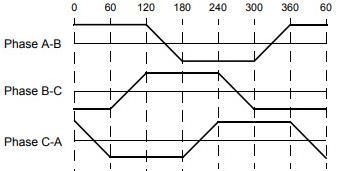
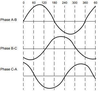
There are different types of back electromotive force (EMF) depending on the type of stator windings which are trapezoidal and sinusoidal. The Figure 12 and Figure 13 show the type of the sinusoidal motor which gives a back EMF sinusoidal and the trapezoidal back EMF of the motor is trapezoidally. Current variations are also trapezoidal and sinusoidal. The torque in a sinusoidal type motor is smoother. Motors rated at forty-eight volts or less are used in 3D printers [15].
Modeling the BLDC motor is essential for its identification and control. The rotor of the BLDC motor consists of a permanent magnet, so it will be modeled as a synchronous motor, however some characteristics are different. The flux linkage of the rotor depends on the material of the magnet [23]. The motor power supply is of the three-phase type, either sinusoidal or another waveform. (7), (8), (9) presents the model for the BLDC motor [24]
Where, ����, ����, ���� are phase voltage (��), �� is armature resistance (Ω), �� is a self-inductance (��), and ����, ����, ���� are motor input current (��). The (10), (11), (12) presents the expression for the back-EMF which is a function of rotor position.
��a =����.��(����)ω (10)
��b =���� ��(����2�� 3 )ω (11)
��c =���� ��(����+ 2�� 3 )ω (12)
Where, ���� is electrical rotor angle, ���� is the back EMF constant of one phase (��/������.�� 1) and ꙍ is an electric speed (������.�� 1). We represent the electrical angle ���� of the rotor in function by the mechanical angle of the rotor ���� multiplied by the number of pairs of poles �� as shown in (13).
����= ������ (13)
The (14) shows that the total output torque ���� is the sum of the torque for each phase. Therefore, the (15) presents the mechanical part which depends on the load torque ���� (����), the moment of inertia of the rotor and the coupled shaft ��(������2) and the frictionconstant ��(������ ������ 1)
The implementation of the brushless motor model is given in Figure 14. The chosen EMF is of trapezoidal type which allows to modify the value of the electrical angle. The stator is powered by an insulated gate bipolar transistor (IGBT) inverter whose control is a function of the rotor position provided by the encoder. This stator is fed in sequence to determine the rotor position and to know which winding will be fed. The speed loop is equipped with a proportional integral (PI) controller to reduce the static error
The Figure 15, Figure 16, Figure 17, and Figure 18 show results of simulations of a BLDC motor with the following parameters wich has the same carachteristics used in 3D printer: �� = 24 V, �� = 1.5 Ω, �� = 1.8 mH, �� = 1.123 10 5 kgm2 , �� = 0.71 Nm. Theoretically, the trapezoidal back EMF shape is driven by rectangular stator currents as shown in Figure 15, which causes a constant torque. However, in practice, the torque exhibits ripple as shown in Figure 16 as well as counter EMF.
Comparative simulation study of electric motors for high performance of 3D printers (Mhamed El Mrabet)
942
Figure 17 shows an example of speed characteristics The motor can run up to maximum speed, but the torque starts to drop. The speed increases linearly at 6000 rpm after 25 ms. The selection of the powered windings depends on the position of the rotor, and can be defined in different ways, the rotor angle increases at 0.6 ms as shown in Figure 18, the rotor angle increases at 0.6 ms as shown in Figure 18.
5.1.
A stepper motor converts electrical energy in the form of current pulses into rotational movement of the rotor. There are 3 types of stepper motor [25]: a) permanent, b) hybrid, and c) variable reluctance. In the case of 3D printers, there is a wide variety of desired features and characteristics. The rotor teeth are attracted by the excited phase of the stator. The excitation of a phase is given by a stepping pulse. We can increase the number of steps of the rotor when we excite two phases at the same time [26].
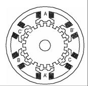
The stator and rotor of hybrid stepper motors consist of salient poles. The stator poles support the coils through which the motor is supplied. The rotor is composed of a permanent magnet with several pairs of poles [27]. The Figure 19 shows the two-phase hybrid stepper motor. This motor consists of a stator which is made up of windings and the rotor which is made up of permanent magnets.
The variable reluctance stepper motor is an energy conversion device with good energy efficiency
It works on the principle of reluctance. Figure 20 shows that the stator and rotor of variable reluctance stepper motors consist of salient poles. The phase number represents the number of poles of the stator [28]. The stator poles are excited with three-phase or single-phase supply and the rotor is either made of permanent magnets or excited with single-phase supply to obtain the rotor magnetic field.
The stator of permanent magnet stepper motors consists of poles that carry coils. The number of poles in the stator determines the number of phases of the motor. The number of pole pairs in the rotor are produced from permanent magnets [29].

The stepper motor is modeled by an electrical and a mechanical part. The single-phase electrical part of hybrid stepper motor is represented by an equivalent circuit ���� and ����() which depends on its position. As shown in Figure 21 reluctance stepper motor wich is used in the 3D printer. We represent also the electrical and mechanical mathematical model of the Hybrid stepper motor.
Where ���� and ���� are the resistance and the inductance of the phase a winding [26]. In this case the inductance ���� approaches a sinusoid and it depends on rotor position as shown in the (16).
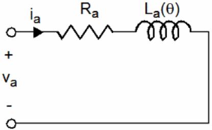
��(��)=��0 +��1cos(������) (16)
��1 is the inductance variation, ��0 is the average inductance and ���� is the number of rotor teeth. The (17) presents a total electromagnetic torque ���� created by the stepper motor:
We have, ���� is the current per phase, �� is the phase number and ���� presents the inductance per phase. The (18) presents the mechanical torque.
���� is load torque, �� is inertia of motor and load, and �� is total friction of motor and load.
The implementation of the stepper motor on Matlab Simulink is given by Figure 22. The stepper motor studied is of hybrid type which is composed of several blocks. The hybrid stepper motor model is established by entering the motor parameters in the simulation. We have chosen a motor with the following characteristics for using in 3D printer: �� = 24 V, �� = 0.63 Ω, �� = 1.03 mH, Step: 1.8°, �� = 82 10-9 kgm2 , �� = 0.15 Nm.
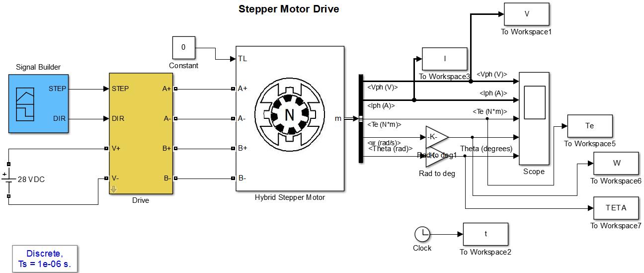
At first the stepper motor is simulated with no load, Figure 23 shows the square waveform of the obtained current using the current amplitude and step specified in the parameters. The motor is supplied with a voltage of 24V. We find that the speed of the stepper motor reaches 3000 tr/min as shown in Figure 24
The Figure 25 presents the variation of the torque with no load and when the load is applied. The rotor position of of stepper motor is determineted directly from the flux, which can be all so calculated form phase current and stator voltage. The initial position of the rotor is determined from four impulses. This parameter is essential for the high performance of the 3D printer. When the phases are supplied, the current reaches a peak. Figure 26 represents the real rotor position estimed from incremental encoder is represented in Figure 26. The rotor position increase at 5 ms.
Comparative simulation study of electric motors for high performance of 3D printers (Mhamed El Mrabet)
The new in this article is the full comparison between PMSM, BLCD, and stepper motor for a great performance of 3D printers.This comparison is established on the modelling of each type of motor and also based on the simulation results found for the nominal torque, the current, the maximum speed, acceleration and rotor position. For a good choice of motor, different comparisons are summarized in the Table 1. The simulations result show the guarantees the start-up of each motors in the desired direction when they used in 3D printer. The obtained results are good in PMSM motor, because it is precise and has a quick response then stepper motor and BLDC motor.
Comparison criteria PMSM BLDC Steeper motor
Currents
Speed/ acceleration
The starting current is seven times the nominal value
PMSM machine offer the best and high dynamic performance Short acceleration response
Rotor position Rotation angle of the motor varies linearly with the input pulse Rotor position response is good and fast
Electromagnetic torque PMSM motor effectively reduces the torque ripple Up to the rated speed, the motor is characterized by a constant torque
BLDC does not require any special starting circuit
The starting current is not so high compared to the rated current
Acceleration isn’t ideal for high-speed applications as 3D printer
In higher power ratings, is interesting in terms of dynamics
Rotation angle of the motor varies linearly with the input pulse Rotor position is not fast
The starting current is higher then the nominal value
Stepper motors aren’t great for dynamic applications
Precise positioning and repeatability of movement
BLDC present high torque ripple Stepper motor gives better torque
The 3D printer has led to increased usage in different fields, and its low cost makes it more affordable to use. One of the most critical components for building a 3D printer is the electric motor. This article has studied the technologies of electric motors used for 3D printers. Their characteristics, the modelling procedure are represented, and simulations results are discussed. A comparison between motors technologies is shown. The BLDC motors are particularly attractive for high-speed applications. However, using them to position oneself would be uninteresting. Stepper motors are great for open loop positioning. However, use them to drive loads with limited maximum speed. The PMSM have an important role in high performance drive systems, they are perfectly suited for precise positioning. The objective of this article is to offer a clear roadmap for the applications of electric motors in 3D printers.
Authors thanks the Abdelmalek-Essaadi University, Tetouan, Morocco.
[1] J. E. Mesbahi, I. B. -Corral, and A. E. Mesbahi, “Use of the QFD method to redesign a new extrusion system for a printing machine for ceramics,” The International Journal of Advanced Manufacturing Technology, vol. 111, pp. 227
242, 2020, doi: 10.1007/s00170-020-05874-x.
[2] J. E. Mesbahi, I. B. -Corral, and A. E. Mesbahi, “Ceramic Paste Extruder of 3D Printing: Status, Types, and Prospects,” International Conference on Integrated Design and Production, CPI 2019: Advances in Integrated Design and Production, 2019, pp 220-229, doi: 10.1007/978-3-030-62199-5_19
[3] M. Boulaala et al. “Towards design of mechanical part and electronic control of multi-material/multicolor fused deposition modeling 3D printing,” The International Journal of Advanced Manufacturing Technology, vol. 110, pp. 45–55, 2020, doi: 10.1007/s00170-020-05847-0
[4] J. Lyu, H. Shen, R. Wang, and N. Rudolph, “Feasible solutions for precise 3D printing: The simulation and proposal,” Proceedings of the 2017 5th International Conference on Mechatronics, Materials, Chemistry and Computer Engineering (ICMMCCE 2017), 2017, doi: 10.2991/icmmcce-17.2017.122
[5] M. Yilmaz, “Limitations/capabilities of electric machine technologies and modeling approaches for electric motor design and analysis in plug-in electric vehicle applications,” Renewable and Sustainable Energy Reviews, 2015, vol. 52, pp. 80-99, doi: 10.1016/j.rser.2015.07.033.
[6] M. Torrent, J. I. Perat, and J. A. Jiménez, “Permanent magnet synchronous motor with different rotor structures for traction motor in high speed trains,” Energies, vol. 11, no 6, 2018, doi: 10.3390/en11061549
[7] M. Mazighe, M. E. Mrabet, and A. Astito, “Hardware in Loop Application DSP F28379D Based Modeling and Implementation of Vector Control for Permanent Magnet Synchronous Motor,” International Conference on Advanced Intelligent Systems for Sustainable Development, AI2SD 2019: Advanced Intelligent Systems for Sustainable Development (AI2SD’2019), 2019, vol. 624, doi: 10.1007/978-3-030-36475-5_13
[8] S. Derammelaere, M. Haemers, J. D Viaene, F. Verbelen, and K. Stockman, “A quantitative comparison between BLDC, PMSM, brushed DC and stepping motor technologies,” 2016 19th International Conference on Electrical Machines and Systems (ICEMS), 2016, pp. 1-5 [Online] Available: https://ieeexplore.ieee.org/document/7837471
[9] M. Bendjedia, Y. A -Amirat, B. Walther, and A. Berthon, “Position Control of a Sensorless Stepper Motor,” in IEEE Transactions on Power Electronics, vol. 27, no. 2, pp. 578-587, 2012, doi: 10.1109/TPEL.2011.2161774.
[10] A. Gundogdu and R. Celikel, “NARMA-L2 controller for stepper motor used in single link manipulator with low-speed-resonance damping,” Engineering Science and Technology, an International Journal, vol. 24, no 2, pp. 360-371, 2021, doi: 10.1016/j.jestch.2020.09.008.
[11] T. -T. Liu, Y. Tan, G. Wu, and S. -M. Wang, “Simulation of PMSM Vector Control System Based on Matlab/Simulink,” 2009 International Conference on MeasuringTechnology and Mechatronics Automation,2009,pp.343-346,doi:10.1109/ICMTMA.2009.117.
[12] D. Mohanraj, J. Gopalakrishnan, B. Chokkalingam, and L. M -Popa, “Critical Aspects of Electric Motor Drive Controllers and Mitigation of Torque Ripple Review,” in IEEE Access, vol. 10, pp. 73635-73674, 2022, doi: 10.1109/ACCESS.2022.3187515.
[13] D. Mohanraj et al., “A Review of BLDC Motor: State of Art, Advanced Control Techniques, and Applications,” in IEEE Access, vol. 10, pp. 54833-54869, 2022, doi: 10.1109/ACCESS.2022.3175011.
[14] A. Bello, I. M. Kilishi, M. M. Bari, and U. Abubakar, “Comparative Review of PMSM and BLDCM Based on Direct Torque Control Method,” International Journal of Scientific & Technology Research, vol. 3, no. 3, pp. 195-199, 2014 [Online]
Available: https://www.ijstr.org/final-print/mar2014/Comparative-Review-Of-Pmsm-And-Bldcm-Based-On-Direct-TorqueControl-Method-.pdf
[15] B. Aranjo, P. K. Soori, and P. Talukder, “Stepper motor drives for robotic applications,” 2012 IEEE International Power Engineering and Optimization Conference Melaka, Malaysia, 2012, pp. 361-366, doi: 10.1109/PEOCO.2012.6230890.
[16] Krishnanand, S. Soni, and M. Taufik, “Design and assembly of fused filament fabrication (FFF) 3D printers,” Materials Today: Proceedings, 2021, vol. 46, pp. 5233-5241, doi: 10.1016/j.matpr.2020.08.627
[17] H. Ali, W. Xuping, M. H. Khan, H. Y. Hiraj, and M. Z. Adil, “Digital proportional amplifier of linear DC electromagnet,” International Journal of Scientific & Engineering Research, vol. 10, no. 10, pp. 257-264, 2019 [Online] Available: https://www.ijser.org/onlineResearchPaperViewer.aspx?Digital-proportional-amplifier-of-linear-DC-electromagnet.pdf
[18] H. Ding, H. Fu, Y. Fan, and X. Shen, “Initial rotor position estimation of SPMSM based on voltage vector injection method,” The International Journal of Advanced Manufacturing Technology, vol. 105, pp.4929–4939, 2019, doi: 10.1007/s00170-019-04201-3
[19] M. L. Mekha and Manju G., “Speed Control of BLDC Motors Using MRAC,” in International Research Journal of Engineering and Technology (IRJET), vol. 3, no. 6, pp. 2329-2334, 2016 [Online] Available: https://www.irjet.net/archives/V3/i6/IRJETV3I6426.pdf
[20] M. Poovizhi, M. S. Kumaran, P. Ragul, L. I. Priyadarshini, and R. Logambal, “Investigation of mathematical modelling of brushless dc motor (BLDC) drives by using MATLAB-SIMULINK,” 2017 International Conference on Power and Embedded Drive Control (ICPEDC), 2017, pp. 178-183, doi: 10.1109/ICPEDC.2017.8081083.
[21] R. Gambhir, A. K. Jha, “Brushless DC motor: Construction and applications,” The International Journal Of Engineering And Science (IJES), vol. 2, no 5, pp. 72-77, 2013. [Online] Available: https://www.theijes.com/papers/v2-i5/Part.3/K0253072077.pdf
[22] S. K. Shanmugam and M. Ramachandran, “Design and implementation of embedded processor based brushless motor drive using lead acid battery as source with lithium ion capacitor,” The Indonesian Journal of Electrical Engineering and Computer Science (IJEECS), vol. 14, no 3, pp. 455-469, 2015 [Online]. Available: https://ijeecs.iaescore.com/index.php/IJEECS/article/view/1498/1139
[23] B. Tibor, V. Fedák, and F. Durovský, “Modeling and simulation of the BLDC motor in MATLAB GUI,” 2011 IEEE International Symposium on Industrial Electronics, 2011, pp. 1403-1407, doi: 10.1109/ISIE.2011.5984365.
[24] W. Liu, J. Cheng, Y. Ma, and C. Jing, “High-precision position control of belt drive system based on OPC communication,” The International Journal of Advanced Manufacturing Technology, vol. 122, pp. 1-10, 2022, doi: 10.1007/s00170-021-07859-w
[25] M. Hojati and A. Baktash, “Design and fabrication of a new hybrid stepper motor with significant improvements in torque density,” Engineering Science and Technology, an International Journal, vol. 24, no. 5, pp. 1116-1122, doi: 10.1016/j.jestch.2021.01.016
[26] H. L. Oo, S. Anatolii, Y. Naung, K. Z. Ye, and Z. M. Khaing, “Modelling and control of an open-loop stepper motor in Matlab/Simulink,” 2017 IEEE Conference of Russian Young Researchers in Electrical and Electronic Engineering (EIConRus), St. Petersburg and Moscow, 2017, pp. 869-872, doi: 10.1109/EIConRus.2017.7910693.
[27] B. Henke, O. Sawodny, S. Schmidt, and R. Neumann, “Modeling of hybrid stepper motors for closed loop operation,” IFAC Proceedings Volumes, 2013, vol. 46, no 5, pp. 177-183, doi: 10.3182/20130410-3-CN-2034.00042
[28] H. Melkote, F. Khorrami, S. Jain, and M. S. Mattice, “Robust adaptive control of variable reluctance stepper motors,” in IEEE Transactions on Control Systems Technology, vol. 7, no. 2, pp. 212-221, 1999, doi: 10.1109/87.748147.
[29] A. M. Harb and A. A. Zaher, “Nonlinear control of permanent magnet stepper motors,” Communications in Nonlinear Science and Numerical Simulation, vol. 9, no 4, pp. 443-458, 2004, doi: 10.1016/S1007-5704(02)00133-8
Mhamed El Mrabet received his Electrical Engineering degree at the National School of Electricity and Mechanics, Casablanca, Morocco, in 1990. He is currently an associate professor attached to Electrical Engineering Department at the Faculty of Science and Techniques of Tangier, Abdelmalek-Essaadi University, Morocco and a member of the Laboratory of Informatics, Systems, and Communications. His current research includes Power Electronics, Control of Power Converters and Electrical Machines. He can be contacted at email: m.elmrabet@gmail.com
Comparative simulation study of electric motors for high performance of 3D printers (Mhamed El Mrabet)

ISSN: 1693-6930
Zineb Mekrini received her Ph.D. degree in Electrical Engineering from Moulay Ismail University, Meknes, Morocco, in 2018. She is now a professor at Electrical Engineering Department in the Faculty of Sciences and Techniques of Tangier, Abdelmalek-Essaadi University, Morocco and a member of the Laboratory of Informatics, Systems, and Communications. Her current research includes the control of power converters, renewable energy, and Fuzzy Logic Control. She can be contacted at email: zineb.mekrini@gmail.com

Abdelilah El Mesbahi received his Degree of Higher Normal School on Technical Education in Mechanical Design, obtained on 1994, ENSET of Mohamedia, Morocco, and his Ph.D. degree in Materials sciences from, defended on 23/09/2006, Faculty of Sciences DharMahraz, Fez and Habilitation to conduct research, Digital Manufacturing: contribution to development of computer product planning (CAPP) in mechanical manufacturing (machining & additive manufacturing), defended on 05/16/2017, FST of Tangier, Morocco. He is currently an associate professor attached to Department of Mechanical Engineering at the Faculty of Science and Techniques of Tangier, AbdelmalekEssaadi University, Morocco and a member of the Team of Industrial Systems Engineering and Energy Conversion. His current research includes 3D printing, robotics and maritime image processing. He can be contacted at email: a.mesbahi@uae.ac.ma

Mohammed Boulaala received his Ph.D. degree in technical sciences from Tula State University, Russia, in 2001. He is currently an associate professor attached to Electrical Engineering Department at the Faculty of Science and Techniques of Tangier, AbdelmalekEssaadi University, Morocco and a member of the Team of Industrial Systems Engineering and Energy Conversion. His current research includes 3D printing, robotics and maritime image processing. He can be contacted at email: m.boulaala@gmail.com