TELKOMNIKA Telecommunication Computing Electronics and Control
Vol. 21, No. 4, August 2023, pp. 917 925
ISSN: 1693-6930, DOI: 10.12928/TELKOMNIKA.v21i4 24432

TELKOMNIKA Telecommunication Computing Electronics and Control
Vol. 21, No. 4, August 2023, pp. 917 925
ISSN: 1693-6930, DOI: 10.12928/TELKOMNIKA.v21i4 24432
Vo Thanh Ha1, Pham Thi Giang2
917
1Department of Cyberntics, Faculty of Electrical and Electronic Engineering, University of Transport and Communications, Hanoi City, Vietnam
2Department of Control and Automation, Faculty of Electrical Engineering, University of Economics-Technology for Industries, Hanoi City, Vietnam
Article Info
Article history:
Received Aug 25, 2022
Revised Nov 29, 2022
Accepted Feb 16, 2023
Keywords:

LQR
PMSM
SVM
T-type inverter
ABSTRACT
This paper presents research on a permanent magnet synchronous motor (PMSM) by a 5-level T-type inverter using linear quadratic regulator (LQR) control for speed control. The space vector modulation (SVM) structure for the 5-level T-type inverter to improve the control quality of the PMSM drive system is presented. This paper aims to successfully design a state feedback controller to control motor speed in a permanent magnet synchronous motor drive system. Simulink results are performed with different speed ranges and the same torque load. These results will focus on evaluating quality when the PMSM drive operates at all speeds. MATLAB/Simulink proves the results.
This is an open access article under the CC BY-SA license.
Corresponding Author:
Vo Thanh Ha
Department of Cyberntics, Faculty of Electrical and Electronic Engineering
University of Transport and Communications, No 3 Cau Giay, Hanoi City, Vietnam
Email: vothanhha.ktd@utc.edu.vn
Nowadays, the permanent magnet synchronous motor (PMSM) transmission system is mainly used in electric vehicle transmission [1], [2]. This drive system requires an electric motor with a lightweight, compact size, large power density, and comprehensive speed control range [3]-[5]. Moreover, the generated torque must be significant if the electric car starts and runs at a low speed. Meanwhile, if the vehicle runs at high speed, it only needs a small torque and can work in the area of flux weakening [6], [7]. In particular, the interior permanent magnet motor (IPM) is most suitable for an electric vehicle transmission. This IPM motor typically has a magnet mounted on the rotor surface which already has excellent control properties. Furthermore, this motor has an interest embedded inside the rotor. Thus, it has a difference between axial inductance and transverse inductance, thereby making it possible to generate reluctance and torque inherent to the magnet [8]. This feature makes this motor capable of generating very high torque, especially suitable for electric vehicles [9]. On the other hand, the IPM motor has a strong armature response, leading to a substantial flux reduction, allowing the speed control area to be raised above the rated speed [10]-[12].
Electric drive systems are implemented with control structures such as scalar control (��/��), direct torque control (DTC), and rotor flux-like (FOC) [13]. In addition, this electric drive structure combines linear, and intelligent control methods for torque control, speed, and position to ensure and improve the quality of electric transmission in terms of speed, precisely as required [14]-[16]. Over more, these electrical drive
Journal homepage: http://telkomnika.uad.ac.id
ISSN: 1693-6930
systems combined multi-level inverters to improve efficiency and reduce the influence on the mains voltage. Based on the research of [17]-[19], multi-level inverters such as neutral point clamped (NPC), cascaded H-bridge (CHB), and T-type have been used for traction drives. These multi-level inverters have many advantages over 2-level inverters for reduced power loss, switching frequency, and sine-like voltage and current shape. Other hand the study, the T-type multi-level inverter has the characteristics of improving voltage quality, torque response, and low total harmonic distortion total harmonic distortion (THD) with low cost. Thus, it is suitable for electric vehicle drive systems [20]-[23]. In this paper, the control system a PMSM motor fed by a 5-level T-type inverter using an linear quadratic regulator (LQR) state feedback control for electric car applications. The LQR algorithm is an automated method of selecting a suitable state-feedback controller. By using this approach, the control systems design to optimize the controller is reduced. In addition, the LQR controller must calculator the cost function parameters following requirements [24]-[26].
The paper is divided into six main parts. Part 1 presents a general overview of the PMSM drive system for electrical vehicle applications. Therefore, the aim study is presented. Next, part 2 shows a mathematical model of a PMSM motor and electric cars to design a speed and torque controller for this system. Then, based on the math model for the drive system design, the article states feedback control for the speed controller. The space vector modulation (SVM) structure for the 5-level T-type inverter to improve the control quality of the PMSM drive system is presented in section 4. Finally, Simulink results from evaluations with different speed ranges and the same load with the same torque to prove the LQR controller’s advantages.
The PMSM motor is controlled by the oriented control (FOC). This FOC method has the advantage of cascade control, and the PMSM motor is handled like a direct current (DC) motor. Thus, the mathematical model of the PMSM motor at the ���� coordinate is expressed as (1)
Where: ������,������ are ���� components of the stator current; ������,������ are ���� components of the stator voltage; ������,������ are ���� components of stator inductance, �� is mechanical speed; ���� is rotor flux; ���� is number of poles. The following equation can be used to determine a permanently excited synchronous motor’s torque:
Because when building a rotor flux-like control system, we will have to control the current vector ����, so that the vertical current vector is perpendicular to the polar flux and thus there is no flux-generating component but only a torque-generating component. So ������ =0, from which the moment equation is obtained:
The modeling task is to determine the relationship between the input and output of the electric vehicle powertrain. First is the motor torque relationship between torque acting on the wheel. The wheel has an interactive relationship with the motor angular speed. The mathematical model of electric cars is shown:
In there: �� is the motor torque; ����ℎ torque acting on the wheel; ����������: gear ratio; ����ℎ,���� are wheel, and motor angular speed. ���� =����ℎ is the load torque; �� is the moment of inertia of the motor, we have the equation of newton’s second law in the rotation of the motor:
Drive wheel model:
Where ����ℎ is wheel radius; ���� is drag force
Based on equations of the PMSM motor and the motor’s rotational torque as (7). The mathematical model of the PMSM motor will transit through the state space model to design LQR control for the speed controller
Transitioning through the state space with:
Design the optimal LQR controller [10] according to the objective function:
Where ��, and �� are two symmetric matrices, �� is positively definite and �� is positive:
Where �� =[��1 ��2 ��3] is the optimal state feedback controller, then �� is calculated by:
Where �� is the solution of the Riccati equation:
1������+�� =0 (14)
Then the control signal is calculated by:
�� = ���� (15)
Choose the value of the matrix �� and �� [11]
�� =1; �� =��′���� (16)
Calculate instead:
�� =[89 0 0 0 38 08] (17)
The traditional 3-phase 2-level voltage source inverter structure is the foundation for the T-type 5-level inverter construction. Six typical semiconductor valves of the same type and six parallel valves producing three T-branches make up the structure (Figure 1). The converter works based on two DC capacitors that divide the input voltage into two components, Vdc/2. This T-type convert establishes a virtual neutral point.
As a result, the output voltage level will be presented as five levels such as 1/2 Vdc, Vdc, 0, +1/2 Vc, and +Vdc, with reasonable adjustment of the transistor valves.
A study on PMSM drive systems fed by multi-level inverter using … (Vo Thanh Ha)
Let
be the switching function:
open and
open
From that, the output phase voltage matrix is built:

result is obtained by simple calculations:
This section expressed MATLAB simulation structure and results evaluation. The control structure of the electric car PMSM drive system fed by a T-type inverter is shown in Figure 2. The speed controller used the LQR method, while the current controller by proportional integral (PI) control.
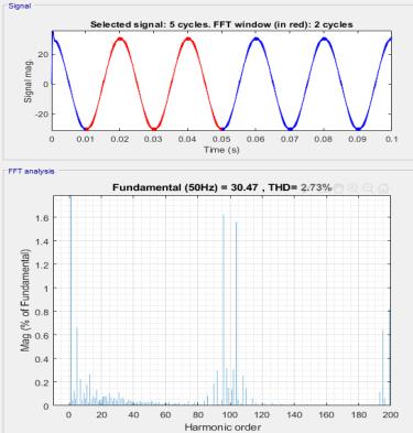
Results of 3-phase 5-level T-type inverter is shown at Figure 3 and Figure 4. Meanwhile, Figure 3 depicts the inverter output voltage response. Figure 4 depicts the current harmonic distortion. It is discovered by simulation results of Figure 3 and Figure 4 that. The inverter output voltage has the form of 5 levels, with an amplitude of 750 V Sine wave output current with low harmonic distortion ������ =2.73% DC voltage on two unbalanced capacitors, with maximum difference up to ������������ =15�� (4.5%).
The MATLAB Simulink results followPMSM parameters, as shown inTable 1. Inthis study, the PMSM motor has four pole pairs, with a max speed is 3000 rpm. The load with inertia moment is 0.00324 kg. ��2
Simulink results are performed with different speed ranges and the same load with the same torque. First, the PMSM motor operates at a very low-speed range at 0 rpm. In addition, this motor operates at a rated speed range at 1500 rpm. Lastly, the PMSM motor reverses repeats at 1500 rpm. These results will focus on evaluating quality when the PMSM drive operates at all speeds.
a) Case 1: a very low-speed range at 0 rpm
In this case, a PMSM can develop torque at zero speed. The PMSM drive was assessed by running the PMSM motor at 0 rpm with a switching torque load and a short duration repeated 1.5 s. Speed responses, motor torque responses, and stator current responses of a PMSM motor are shown in Figure 5 to Figure 8.
A study on PMSM drive systems fed by multi-level inverter using … (Vo Thanh Ha)


Figure 5 shows that speed responses can be seen in the overshoot at 250 rpm with a setting time of 0.05 s. In addition, Figure 6 shows that motor torque output has an overshoot when the motor switches to a working state with an overshoots torque of 40%. Meanwhile, Figure 7 and Figure 8 are expressed with a load with variable torque repeatedly equal to the motor’s rated torque. The motor’s speed response at 0 rpm is fast. The motor has kept the shaft stationary after 0.05 s.


b) Case 2: a rated speed range at 1500 rpm
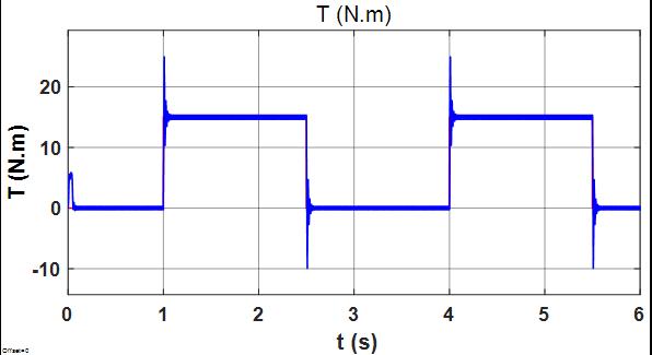
In this case, the PMSM operates at the rated speed by running the motor at 1500 rpm. In addition, the PMSM drive will work the transmission system by continuously changing load mode within a short time of 1.5 s. As a result, the load moment is constant (15 Nm, and 0 Nm).
Figure 9 is the speed response of the motor. From the picture, it can be seen that the overshoot at 250 rpm and the setting time at 0.05 s. Figure 10 is the motor torque, Figure 11 is ������ and ������ voltage, and Figure 12 is the stator current of the motor. With a variable torque load repeatedly equal to the rated torque of the motor, the speed response at 1500 rpmof the motor is fast, after 0.05 s, the motor has reached the set speed.
c) Case 3: reversing a repeat at rated speed of 1500 rpm
In this case, the motor accelerates and decelerates rapidly in 1.5 s, and reverses the motor with a constant load equal to the rated torque. Figure 13 shows the speed response of the motor. From the picture, it can be seen that the overshoot and the setting time are slight. Figure 14 is the motor torque, and Figure 15 is ������ and ������ voltage, and Figure16 is the stator current of the motor.

Based on the response results, when the PMSM motor is completely working at the range at a fast reversing, increasing, and decreasing speed. This speed LQR controller can work with short-term loads, and continuous changing is excellent. The rate responds with a slight overshoot and a fast-setting time. The stator currents have a sine wave.


This paper presents the LQR control is designed to speed control a PMSM motor fed by a 5-level T-type inverter with fast speed response and lower over-throttling. Therefore, the quality of the PMSM electric drive will be improved. However, to enhance the quality of PMSM electric drive so that the speed adjustment is faster and more accurate by using linear, predictive, and intelligent cost control methods. Also, extend the operating speed range ofa PMSM inthe flux attenuationregion using the maximum torque per ampere (MTPA) method.

[1] X. Zhang, L. Zeng, and R. Pei, “Designing and comparison of permanent magnet synchronous reluctance motors and conventional motors in electric vehicles,” in 2018 21st International Conference on Electrical Machines and Systems (ICEMS), 2018, pp. 202-205, doi: 10.23919/ICEMS.2018.8549102.
[2] Z. An, “Design of permanent magnet synchronous motor for electric vehicle,” Journal of Physics: Conference Series, 2021, vol. 1881, doi: 10.1088/1742-6596/1881/2/022071
[3] C. Gong, Y. Hu, G. Chen, H. Wen, Z. Wang, and K. Ni, “A DC-bus capacitor discharge stratagy for PMSM drive system with large inertia and small system safe current in EVs,” IEEE Transactions on Industrial Informatics, vol. 15, no. 8, pp. 4709-4718, 2019, doi: 10.1109/TII.2019.2895317.
[4] A. Loganayaki and R. B. Kumar, “Permanent magnet synchronous motor for electric vehicle applications,” in 2019 5th International Conference on Advanced Computing & Communication Systems (ICACCS),2019,pp.1064-1069,doi:10.1109/ICACCS.2019.8728442
[5] Y. Miyama, H. Hijikata, Y. Sakai, K. Akatsu, H. Arita, and A. Daikoku, “Variable characteristics technique on permanent magnet motor for electric vehicles traction system,” in 2015 IEEE International Electric Machines & Drives Conference (IEMDC), 2015, pp. 596-599, doi: 10.1109/IEMDC.2015.7409119
[6] R. Wang, X. Jia, S. Dong, and Q. Zhang, “PMSM driving system design for electric vehicle application based on bidirectional quasi z-source inverter,” 2018 13 th IEEE Conference On Industrial Electronics and Applications (ICIEA), 2018, pp. 1733-1738, doi: 10.1109/ICIEA.2018.8397989.
[7] P. B. Reddy, A. M. El-Eirafie, K. -K. Huh, J. K. Tangudu, and T. M. Jahns, “Comparision of interior and surface PM machines equipped with fractional-slot concentrated windings for hybrid traction applications,” IEEE Transactions on Energy Conversion, vol. 27, no. 3, pp. 593-602, 2012, doi: 10.1109/TEC.2012.2195316
[8] Z. E. Idrissi, H. E. Fadil, and F. Giri, “Nonlinear control of salient pole-PMSM for electric vehicle traction,” in 2018 19th IEEE Mediterranean Electrotechnical Conference (MELECON), 2018, pp. 231-236, doi: 10.1109/MELCON.2018.8379099
[9] Y. Zhang, W. P. Cao, and J. Morrow, “Interior permanent magnet motor parameter torque ripple analysis for EV traction,” in 2015 IEEE International Conference on Applied Superconductivity And Electromagnetic Devices (ASEMD), 2015, pp. 386-387, doi: 10.1109/ASEMD.2015.7453625.

[10] H Ying, S Huang, and D Xu, “An high speed low-noise rotor topology for EV/HEV PMSM,” CES Transactions on Electrical Machines and Systems, vol. 1, no. 4, pp. 354-359, 2017, doi: 10.23919/TEMS.2017.8241356.
[11] S. P. Emami, E. Roshandel, A. Mahmoudi, and S. Khaourzade, “IPM motor optimization for electric vehicles considering driving cycles,” in 2021 31st Australasian Universities Power Engineering Conference (AUPEC), 2021, pp. 1-5, doi: 10.1109/AUPEC52110.2021.9597815.
[12] M. A. Rahman, “IPM motor drives for hybrid electric vehicles,” in 2007 International Aegean Conference on Electrical Machines and Power Electronics, 2007, pp. 109-115, doi: 10.1109/ACEMP.2007.4510492
[13] C. -B. Park and G. Jeong, “Design and analysis of magnetic geared peranent magnet synchronous motor for driving electric vehicles,” 2017 20th International Conference on Electrical Machines and Systems (ICEMS),2017,pp.1-5,doi:10.1109/ICEMS.2017.8056127.
[14] W. Yi and Z. Kaiqi, “Field-oriented vector control of induction motor for electric vehicles,” in 31st Annual Conference of IEEE Industrial Electronics Society, 2005, doi: 10.1109/IECON.2005.1569145.
[15] V. T. Ha, T. T. Minh, N. T. Lam, and N. H. Quang, “Experiment based comparative analysis of stator current controllers using predictive current control and proportional integral control for induction motors,” Bulletin of Electrical Engineering and Informatics, vol. 9, no. 4, pp. 1662-1669, 2020, doi: 10.11591/eei.v9i4.2084.
[16] V. T. Ha, N. T. Lam, P. V. Tuan, N. H. Quang, “Experiment-based comparative analysis of nonlinear speed control methods for induction
motors,” Journal of Engineering and Technological Sciences,vol.53,no.2,2021,doi:10.5614/j.eng.technol.sci.2021.53.2.12.
[17] W. Qinglong, Y. Changzhou, and Y. Shuying, “Indirect field oriented control technology for asynchronous motor of electric vehicle,” in 2020 IEEE International Conference on Power, Intelligent Computing and Systems (ICPICS), 2020, pp. 673-677, doi: 10.1109/ICPICS50287.2020.9201983.
[18] V. T. Ha, P. T. Giang, and P. Vu, “Multilevel inverter application for railway traction motor control,” Bulletin of Electrical Engineering and Informatics, vol. 11, no. 4, pp. 1855-1866, 2022, doi: 10.11591/eei.v11i4.3964
[19] C. M. Van, T. N. Xuan, P. V. Hoang, M. T. Trong, S. P. Cong, and L. N. Van, “A generalized space vector modulation for cascaded H-bridge multi-level inverter,” in 2019 International Conference on System Science and Engineering (ICSSE), 2019, pp. 18-24, doi: 10.1109/ICSSE.2019.8823465
[20] P. T. Giang, V. T. Ha, V. H. Phuong, “Drive control of a permanent magnet synchronous motor fed by a multi-level inverter for electric vehicle application,” Engineering, Technology & Applied Science Research, vol. 12, no. 3, pp. 8658-8666, 2022, doi: 10.48084/etasr.4935.
[21] V. T. Ha, P. T. Giang, V. H. Phuong, “T-type multi-inverter application for traction motor control,” Engineering, Technology & Applied Science Research, vol. 12, no. 2, pp. 8321-8327, 2022, doi: 10.48084/etasr.4776.

[22] P. Vu, D. T. Anh, and H. D. Chinh, “A novel modeling and control design of the current-fed dual active bridge converter under DPDPS modulation,” Engineering, Technology & Applied Science Research, vol. 11, no. 2, pp. 7054–7059, 2021, doi: 10.48084/etasr.4067.
[23] A. Sheir, M. Z. Youssef, and M. Orabi, “A novel bidirectional T-type multilevel inverter for electric vehicle applications,” IEEE Transactions on Power Electronics, vol. 34, no. 7, pp. 6648-6658, 2019, doi: 10.1109/TPEL.2018.2871624
[24] H. Purnawan, Mardlijah, and E. B. Purwanto, “Design of linear quadratic regulator (LQR) control system for flight stability of LSU-05,” Journal of Physics: Conference Series, 2017, vol. 890, doi: 10.1088/1742-6596/890/1/012056.
[25] T. Shi, Y. Yan, Z. Zhou, M. Xiao, and C. Xia, “Linear quadratic regulator control for PMSM drive systems using nonlinear disturbance observer,” IEEE Transactions on Power Electronics,vol.35,no.5,pp.5093-5101,2020,doi:10.1109/TPEL.2019.2947259.
[26] O. A. Dhewa, A. Dharmawan, and T. K. Priyambodo, “Model of linear quadratic regulator (LQR) Control method in hovering state of quadrotor,” Journal of Telecommunication, Electronic and Computer Engineering, vol. 9, no. 3, pp. 135-143, 2017. [Online]. Available: https://jtec.utem.edu.my/jtec/article/view/1589/1891
Vo Thanh Ha is a lecturer in the Faculty of Electrical and Electrical Engineering, University of Transport and Communications. She received her B.S degree in Control, and Automation Engineering from the Thai Nguyen University of Technology, Vietnam, in 2002. She received her Master’s degree from the Hanoi University of Science and Technology, Vietnam, in 2004. She received a Ph.D. degree from the Hanoi University of Science and Technology, Viet Nam, in 2020, both in Control and Automation Engineering. Her research interests include the field of electrical drive systems, power electronics, and electric vehicles. She can be contacted at email: vothanhha.ktd@utc.edu.vn.
Pham Thi Giang received her B.S. She graduated with a master’s degree in automation and control engineering from Hanoi University of Science and Technology, Hanoi, Vietnam in 2022. She is currently working at University of Economics - Industrial Technology, Hanoi, Vietnam. Her research interests include power electronic and electrical powertrain systems. She can be contacted at email: ptgiang@uneti.edu.vn.
A study on PMSM drive systems fed by multi-level inverter using … (Vo Thanh Ha)
