Email: le.px@vlu.edu.vn
ABSTRACT
Faculty of Mechanical Electrical and Computer Engineering, School of Engineering and Technology Van Lang University, Ho Chi Minh City, Vietnam
1Faculty of Fundamental Science, Industrial University of Ho Chi Minh City, Ho Chi Minh City, Vietnam
Revised Jun 17, 2022
Dual layer phosphor
TELKOMNIKA Telecommunication Computing Electronics and Control
ISSN: 1693 6930, DOI: 10.12928/TELKOMNIKA.v20i5 24080 homepage: http://telkomnika.uad.ac.id
Luminous efficacy
Corresponding Author: Phan Xuan Le
1. INTRODUCTION
The development of solid state electronics (SSE), pieces of electronic equipment using semiconductors, has created a revolution in technology and portable electronic devices. In lighting technology, one of the most popular SSE semiconductor devices is light emitting diodes (LEDs). Producing white light using LED chips that emit light in the blue wavelength and coating layers made of light converted materials can be a potential method. The improvements for white light color and lumen adequacies have been introduced to various studies as the main objective. By succeeding in utilizing fine tuning the yttrium alum garnet (YAG) phosphor structure, the luminescent power of white LEDs (W LEDs) can be greatly improved [1] [3]. However, since these devices are lack of red portion in their spectra, they could not fulfill lighting applications that demand low correlated color temperatures (CCTs) with high color rendering index’s (CRIs) [4], [5]. One of the practical alternatives to the conventional yellow phosphor is the quantum dot (QD) because it presents a strong quantum yield (QY), and a tunable emission spectrum. Industrial CdSe/ZnS QDs with red emissions,
Article history:
Article Info
Accepted Jun 27, 2022
Vol. 20, No. 5, October 2022, pp. 1125~1131
Received May 18, 2021
Phuc Dang Huu1 , Phan Xuan Le2
Keywords:

Mie scattering theory
1125 Journal
Chroma consistency and luminous efficacy for a WLED using remote phosphor configuration with a tri-layer design
Triple layer phosphor
This is an open access article under the CC BY SA license.
2Faculty of Mechanical Electrical and Computer Engineering, School of Engineering and Technology, Van Lang University, Ho Chi Minh City, Vietnam
The light quality of white light emitting diodes (WLEDs), an essential element for the improvement of WLEDs performance, can now be estimated by the angular color uniformity (ACU). In this study, a single micro patterned layer is used to compare the variations between the traditional remote phosphor (RP) layer and the remote phosphor layer (single remote micro patterned phosphor film (RMPP) layer). Furthermore, we investigate the application of a novel triple remote phosphor layer to improve the ACU in RP down light lamps. Besides, the optical efficiency of the layers as well as the distribution for the angular correlated color temperature (ACCT) were also measured experimentally. According to the findings, the dual RMPP layer structure can achieve better chromatic uniformity with just 441 K of correlated color temperature (CCT) variance. Meanwhile, the single RMPP layer shows an ACCT deviation of 556 K and RP film structure of 1390 K. The simulation incorporating e finite difference time domain (FDTD) as well as the approach of ray tracing ensures an increase in ACU. Furthermore, compare to the traditional RP layer, the single and dual RMPP layers configuration result in respective luminous efficiency ameliorations of 6.68% and 4.69%. The scattering principle and combining influence from the micro molded layer may explain the enhancement in ACU as well as lumen
Color rendering index
Table 2. Constituents for CnS:In Ingredients Mole % By weight (g)
were commonly used for stimulating the strength of red spectral energy in the white LEDs [6] [8]. However, compared to the typical white LEDs with the rare earth base, the W LEDs with QDs exhibit inferior performance stability, which considerably put a limit on their practical utilities. The primary issue emerging when applying QDs is the poor stability in their thermal reaction feature that even rapidly degrades under high temperature conditions. Furthermore, despite a high QY of more than 90%, the QDs suffer from high reabsorption loss in white LEDs, initiating an increasing thermal production. To address this problem, introducing the QD film with a sphere shell structure functioning as a blue anti reflection layer can be potential. It did reduce the absorption loss by limiting the total light reflection in the package and eventually increase the capability to stabilize the thermal generation of QD W LEDs. Furthermore, from a liquid substance to a solid polymer matrix converting process the QY of QDs, and the thermal stability can be improved by liquid type packing methods using the minimizing thermal power generation [9], [10]. Nevertheless, the issues related to high thermal production when using the QD are still challenging since the surrounding polymer matrix provides inefficient thermal conductivity. Besides, it is difficult to manage to obtain the thermal reduction and stability for the QD sheet by just introducing materials offering strong thermal conductivity, like the hexagonal boron nitride (h BN). Furthermore, the QD layer usually plays a role as a coating layer on the LED chip cluster, which produces a lot of heat during operation, reducing QD heat distribution even more [11], [12].
Table 1. Constituents for YasO4:Eu3+ Ingredients Mole % By weight (g)
2. PREPARATION
CdS 100 145
TELKOMNIKA Telecommun Comput El Control, Vol. 20, No. 5, October 2022: 1125 1131
In2O3 0.1 (of In) 0.139
In this research, we suggest a metal based inverted design (MID) that boosts the thermal efficiency of QD W LEDs by reducing thermal shift between the LED chip and the QD layer. First, based on the laser driven experimental platform, we figure the thermal impacts of a LED chip as a heating resource of the light conversion film on its surface. Then, by changing the QD and phosphor concentrations, the modification on MID QD W LEDs can be introduced to obtain higher optical efficiency. Finally, the optimized MID QD white LED’s thermal efficiency and stability are discussed. We successfully obtained CCT as well as CRI deviations of 57.3 K and 0.29, owing to effectively dissipating the heat of the QD layer by the metal based inverted packaging (MIP) structure at injection power values ranging from 0.08 W 1.3 W. Moreover, after aging for 10 hours under extreme conditions, the system shows only a minor reduction in optical and color output.
Y2O3 95 (of Y) 107
For the green emitting CnS:In phosphor preparation, In2O3 is initially dissolved in nitric acid, and CdS is subsequently introduced, forming a slurry in methanol. The substance is left desiccated, then pulverized. Approximately 2 g 3 g of sulfur is added to the mixture before it is burned within closed quartz pipes accompanied by H2S under 900 °C within an hour. When the mixture is cool, inspect it under UV light to see if it exhibits red luminescence. Get rid of every portion if it looks disparate and then pulverize. For the next burning process, the powder is heated at 500 °C within open quartz boats filled with H2. Then examine it through UV light again, the substance will be in uniform green. The green YasO4:Eu3+ phosphor’s emission peak is at 2.39 eV, emission width (FWHM) is at 0.08 eV. The excitation efficacy by UV is +(4.88 eV), +(3.40 eV). The structure appears to be hexagonal or wurtzite.
Preparing stages of both red and green phosphors, YasO4:Eu3+ and CnS:In, are individually demonstrated this section. Table 1 and Table 2 detail the essential information of YasO4:Eu3+ and CnS:In compositions, respectively. To acquire the red emitting phosphor YasO4:Eu3+, a complete slurry comprised of all chemical components is made with 30% H2O2. The slurry is then heated up gently, accompanied by stirring to the point of reactivity or seething, which designates that the H3AsO4 has been formed. After that, the mixture is dried in air and powdered. Next, the open quartz boat that contains the powder is burnt at approximately 500 °C. When the burning time is over, take this mixture out and powderize it. The next firing is carried out at 1200 °C, with the powder in an open quartz boat, and lasts one hour. The emission peaks of the red YasO4:Eu3+ phosphor are within 1.76 eV 2.09 eV. The ultraviolet (UV) excitation efficacy is (4.88 eV), (3.40 eV). The structure is tetragonal or xenotime [13], [14]
As2O3 100 (of As) 75
1126forexample,
Eu2O3 5 (of Eu) 8.8
ISSN: 1693 6930
TELKOMNIKA Telecommun Comput El Control
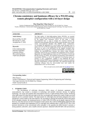
Figure 1. The cross section illustrations: (a) double sheet RP (DRP) and (b) three sheet RP (TRP)
Our study examined the performances of lighting features of two W LEDs using remote phosphor (RP) packages: the dual layer RP (DRP) with yellow, red phosphor sheets and three sheet RP (TRP) containing green as well as red phosphor sheets aside from the yellow one. Both packages utilize flat phosphor films that cover the cluster of nine LED chips. The cross section illustrations of DRP are described in Figures 1(a) and the cross section illustrations of TRP are described in Figure 1(b), respectively. The red layer is placed highest while the yellow layer is placed closest to the LED chip surfaces, in both W LED packages. Meanwhile, the green phosphor layer of the TRP is the middle layer; in other words, this phosphor film is placed above the yellow and below the red phosphor films, see Figure 1(b). In addition, the LED chips are represented by the blue zones, the phosphor layer by the yellow zones, and the silicone matrix lenses by the blank zones. Aluminum nitride is thought to be the substrate, whereas YAG:Ce3+ is thought to be the phosphor. When observing along the z axis, all of the CCTs in each structure are set to 6500 K [15], [16]. The thickness of these phosphor sheets would be 0.08 mm. Furthermore, the YAG:Ce3+ content varies in response to shifts in the concentrations of red, green, or red phosphor in order to preserve the median CCTs (ACCTs). Furthermore, the YAG:Ce3+ concentrations vary depending on the angular correlated color temperature (ACCT) of each phosphor structure, resulting in a wide range of scattering characteristics within WLEDs. Furthermore, variations in optical properties result from this discrepancy.
Figure 3 Discharge spectra in DRP as well as TRP packages
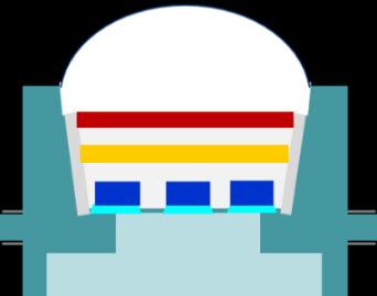
Figure 2. The YAG:Ce3+ content in DRP and TRP structures
(a) (b)

1127
Chroma consistency and luminous efficacy for a WLED using … (Phuc Dang Huu)
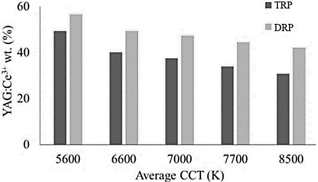
Yellow YAG:Ce3+ phosphor concentrations with the red and green phosphor films introduced to the DRP and TRP are demonstrated in Figure 2. The DRP obviously shows the more significant yellow phosphor concentration than the TRP, in all ACCTs. Greater concentrations of yellow phosphor YAG:Ce3+ can lead to a higher probability of back scattering events occurring. In other words, unless the reduction in YAG:Ce3+ is acquired, the light scattering in the backward direction will increase in amount, reducing the emitted luminous flux. When the concentration of YAG:Ce3+ is increased, however, a disparity among the key hues generating white, yellow, red, as well as green illumination, resulting in decreased color quality. As a result, back scattering must be minimized by increasing the red light portion to yield greater lumen as well as chromatic output in WLED devices. Furthermore, the green light can regulate chromatic uniformity and luminous flux. Would the TRP become the best in terms of handling light attributes based on this information? the spectral emission computation and demonstration of DRP and TRP in the next section could provide the answer, see Figure 3.
ISSN: 1693 6930 Telecommun Comput El Control, Vol. 20, No. 5, October 2022: 1125 1131
The (1) and (2) are applied for computing the propagated blue illumination along with the transmuted yellow illumination of the SRP, while the (3) and (4) are used for those of the DRP. The phosphor film’s thickness is 2ℎ in the SRP and ℎ in the DRP [17] [21]
1128
Though multi layer RP structures could promote chroma adequacy, their luminous intensity (LI) may get declined. This is unavoidable as the stimulated scattering factor can cause the LI to decrease. Yet, the question is if multi layer RP can give better LI than single layer RP (SRP). The lighting intensity computation could give a proper demonstration. The expressions for propagated blue illumination as well as transmuted yellow illumination of the DRP as well as SRP are shown to serve this purpose.
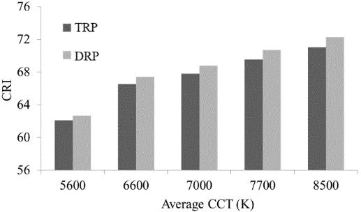
Figure 4. CRIs in TRP and DRP settings Figure 5. CQS in TRP and DRP configurations
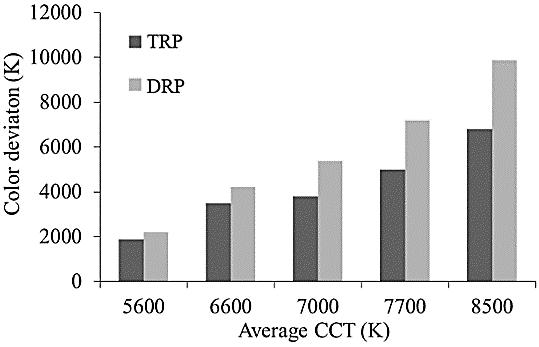
CH, additionally, is another critical aspect of chroma adequacy. Various approaches are available for augmenting CH, such as employing phosphor granules to increase scatterings (SiO2 and CaCO3) or using a conformal phosphor structure. Despite the fact that these two methods can increase CH, the luminous flux appears to be decreasing. The application of these RP structures in this article could lead to noticeable improvements in CH. When the green CnS:In and red YasO4:Eu3+ phosphors are applied, the dispersion, along with the green as well as red illumination components within the WLED device are increased, resulting in a better white light generation. Additionally, the backscattering degradation, provided by the RP structures, will boost the emitted luminous flux. To further demonstrate this point, the hue aberration of the DRP as well as TRP is shown in Figure 6. The DRP apparently gives a greater correlated color temperature deviation (D CCT) value than the TRP; however, the lower the variance, the better the color uniformity. In other words, the TRP is more efficient in CH performance. This argument is shown via the inner dispersion within the WLED device, as additional sheets of phosphor can result in more occurring scattering events for enhancing color balance; as a result, CH improves. However, an increase in scattering events may result in a decrease in luminous output (LO) but this might be accepted since acquiring the back scattering reduction is more critical to the RP structures.
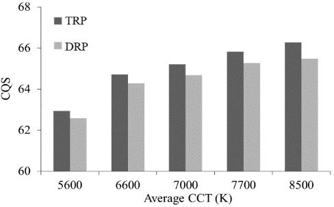
The CRI comparison between the remote phosphor configurations is shown in Figure 4. As can be noticed, regardless of ACCT, the DRP gets the better CRI. The CRI of this structure, in particular, rises with each ACCT, reaching its sharp peak at an ACCT of 8500 K. This finding contributes greatly to the improvement of chromatic adequacy of the white light LED devices, notably for models with high pre set ACCTs (7000 K 8500 K, for example). Controlling the CRI at a greater ACCT has been regarded as a challenging task, it is possibly addressed by using the DRP consisting red phosphor layer of YasO4:Eu3+ As a result of YasO4:Eu3+ film deposition, the stimulation of red spectra is acquired, leading to improving CRI figures. The TRP also displays the potential to enhance the CRI but somehow is not as significant as the DRP. CRI, on the other hand, can just evaluate a single factor in white light color adequacy. There is also a drawback in CRI assessment, the projected light with a large amount of red or blue elements is possible to give significant CRI values. This implies that the light with high CRI may not exhibit great color homogeneity (CH). In fact, CRI is included in color quality scale (CQS), color quality scale a color rendering score introduced by National Institute of Standards and Technology (NIST). Apart from CRI, CQS comprises viewer preference and chromaticity coordinate, making it a more interesting metric for researchers and a more effective approach to color assessment. Figure 5 compares the CQS of TRP and DRP structures. A notably greater CQS figure can be reported in TRP structures, regardless of ACCT numbers. The balance between generated red, yellow, and green spectra could amplify the CH of the TRP structure, resulting in a significant enhancement of CQS. These findings possibly concrete the foundation of using multi layer RPs for optical enhancements, especially the color adequacy of the W LEDs. Particularly, the DRP using red YasO4:Eu3+ may be ideal for CRI encouragement, while TRP with both red YasO4:Eu3+ and green CnS:In is more appropriate for CQS efficiency.
3. RESULTS AND DISCUSSION
TELKOMNIKA
6. D
µ����. µ������ =���� ��������
TELKOMNIKA Telecommun Comput El Control Chroma consistency and luminous efficacy for a WLED using … (Phuc Dang Huu) 1129 ����1 =����0 ×�� 2����1ℎ (1) ����1 = 1 2 ��1×����0 ����1 ����1 (�� 2����1ℎ �� 2����1ℎ) (2) ����2 =����0 ×�� 2����2ℎ (3) ����2 = 1 2 ��2×����0 ����2 ����2 (�� 2����2ℎ �� 2����2ℎ) (4)
(����2+����2) (����1+����1) ����1+����1 >0
In which, ��0, ��, and µ������ denote the power of incident lights, the phosphor film’s breadth (mm), and the extinction coefficient, respectively. The (7) will determine (7)
Where ℎ denotes the phosphor sheet’s breadth within the RPpackage. The SRPand DRPare indicated by numbers 1 and 2 in subscript, respectively. The coefficients of blue illumination conversion and yellow illumination reflection will be denoted by �� and ��, respectively. The blue illumination (PB) as well as yellow illumination (PY) intensities will be presented by PB0. B shows the energy loss ratio of the blue light, and �� presents that of the yellow light during the illumination propagating process in the RP packages. As compared to the SRP, the DRP could get the pc LED’s perforamnce greatly improved [22], [23]. (5)
The Mie hypothesis will be employed for studying phosphor particle scattering, from which it is possible to acquire the dispersing cross section �������� in the case of phosphor spheres [24] [26]. The use of the Lambert Beer law can also help measure the power of the transmitted (6)
�� =��0 ������( µ��������)
Figure CCT of TRP and DRP settings
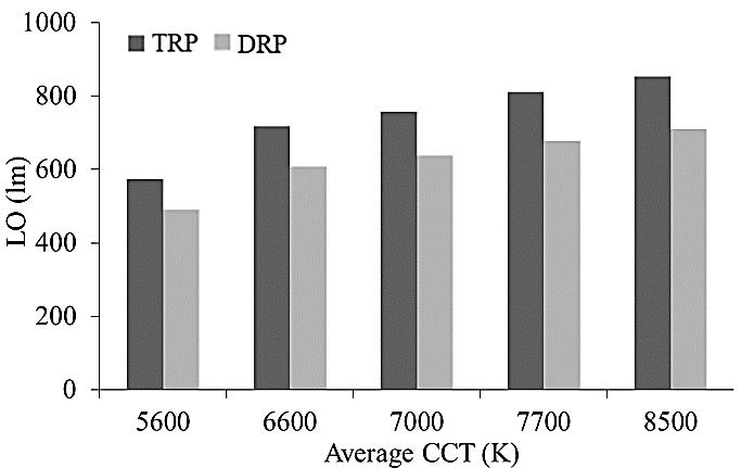
���� (mm 3) denotes the particle number density allocation. �������� (mm2) defines the particle extinction cross section.The(5) demonstrated that applying several phosphor layers improves the luminous flux more than applying only one. Moreover, the Lambert Beer law in (6) notes that when using multi layer RP, the phosphor concentration must be changed to a sufficient level to obtain the maximum power transmission. Figure 7 clearly demonstrates this finding. Specifically, the TRP shows stronger LI than the DRP does, removing any doubts about the advantages of TRP in terms of luminous flux. The green phosphor layer CnS:In in the TRP improves the portion of green coloration owing to the notably broadened 500 nm 600 nm emission spectrum. Besides, contributing to the greater emission intensity of TRP is the significant reduction in YAG:Ce3+ phosphor concentration as a function to maintain the ACCT. Notably, this yellow concentration reduction is more remarkable than that of the DRP, leading to that the TRP is superior in minimizing internal back scattering lights. When the backscattering is minimized, the LED chip emitted blue light is allowed to pass through YAG:Ce3+ layer more easily, enhancing the chances for these lights to interact with the other phosphor layers and get converted. In other words, the TRP manages to perform an efficient blue light conversion to boost the blue light power from LED chips, which eventually benefits the emission strength of the white light region for the greatest enhancement in luminous flux. Hence, when the manufacturer aims at superior CQS, CH, and LI for WLEDs, the TRP structure can be selected.
[6] X. Wang, Y Wang, J Yu, Y Bu, and X Yan, "Modifying phase, shape and optical thermometry of NaGdF4:2%Er3+ phosphors through Ca2+ doping," Optics Express, vol. 26, no. 17, pp. 21950 21959, 2018, doi: 10.1364/OE.26.021950.
ACKNOWLEDGEMENTS
REFERENCES
[9] D. Durmus and W Davis, "Blur perception and visual clarity in light projection systems," Optics Express, vol. 27, no. 4, pp. A216 A223, 2019, doi: 10.1364/OE.27.00A216.
[11] J. Zhou and K Qian, "Low voltage wide field of view lidar scanning system based on a MEMS mirror," Applied Optics, vol. 58, no. 5, pp. A283 A290, 2019, doi: 10.1364/AO.58.00A283.
TELKOMNIKA Telecommun Comput El Control, Vol. 20, No. 5, October 2022: 1125 1131
1130
Figure 7. Correlation between luminous output of phosphor settings and ACCTs
[7] X. Fu et al., "Micromachined extrinsic Fabry Pérot cavity for low frequency acoustic wave sensing," Optics Express, vol. 27, no. 17, pp. 24300 24310, 2019, doi: 10.1364/OE.27.024300.
[8] A. Ullah et al., "Household light source for potent photo dynamic antimicrobial effect and wound healing in an infective animal model," Biomedical Optics Express, vol. 9, no. 3, pp. 1006 1019, 2018, doi: 10.1364/BOE.9.001006.
ISSN: 1693 6930
[2] X. Kong, M. Wei, M J. Murdoch, I Vogels, and I Heynderickx, "Assessing the temporal uniformity of CIELAB hue angle," Journal of the Optical Society of America A, vol. 37, no. 4, pp. 521 528, 2020, doi: 10.1364/JOSAA.384393.
[12] J. S. Li, Y. Tang, Z. T. Li, L. S. Rao, X. R. Ding, and B. H. Yu, "High efficiency solid liquid hybrid state quantum dot light emitting diodes," Photonics Research, vol. 6, no. 12, pp. 1107 1115, 2018, doi: 10.1364/PRJ.6.001107.
[4] S. Pan, B Yang, X Xie, and Z Yun, "Image restoration and color fusion of digital microscopes," Applied Optics, vol. 58, no. 9, pp. 2183 2189, 2019, doi: 10.1364/AO.58.002183.
[13] S. Lee et al., "Printed cylindrical lens pair for application to the seam concealment in tiled displays," Optics Express, vol. 26, no. 2, pp. 824 834, 2018, doi: 10.1364/OE.26.000824.
[14] H. Yuce, T Guner, S Balci, and M M. Demir, "Phosphor based white LED by various glassy particles: control over luminous efficiency," Optics Letters, vol. 44, no. 3, pp. 479 482, 2019, doi: 10.1364/OL.44.000479.
The performances offered by DRP and TRP layouts in WLEDs with five pre set ACCTs are compared in this paper. During the simulation, the green CnS:In and red YasO4:Eu3+ phosphors are used. The Mie hypothesis, along with the law of Lambert Beer, validates the study findings. According to the findings, the addition of a green CnS:In phosphor layer improves the green light portion, resulting in improved color uniformity and luminous performance. As a consequence, the TRP layout yields more luminous flux and chromatic consistency, surpassing the DRP layout. Furthermore, increasing the red light portion by using a red YasO4:Eu3+ phosphor layer will enhance the CRI and CQS. The TRP structure has a higher CRI and CQS than the DRP structure, as shown in the result. It’s clear that chromaticity is determined by the balance control over red , yellow , green , and blue color proportions, which is achievable with TRP. Furthermore, the TRP structure’s luminous flux increases noticeably as the occurring backscattered lights are reduced. In addition, from the figures, that TRP has a stronger LI than the DRP is obvious evidence. The manufacturer can consider the priority of the optical properties for their products while referencing the findings in our work to get a proper RP structure for WLED production.
[1] S. Sadeghi, B. G. Kumar, R. Melikov, M. M. Aria, H. B. Jalali, and S. Nizamoglu, "Quantum dot white LEDs with high luminous efficiency," Optica, vol. 5, No. 7, pp. 793 802, 2018, doi: 10.1364/OPTICA.5.000793.
[5] B. K. Tsai, C C. Cooksey, D W. Allen, C C. White, E Byrd, and D Jacobs, "Exposure study on UV induced degradation of PTFE and ceramic optical diffusers," Applied Optics, vol. 58, no. 5, pp. 1215 1222, 2019, doi: 10.1364/AO.58.001215.
[10] A. Lihachev, I Lihacova, E V. Plorina, M Lange, A Derjabo, and J Spigulis, "Differentiation of seborrheic keratosis from basal cell carcinoma, nevi and melanoma by RGB autofluorescence imaging," Biomedical Optics Express, vol. 9, no. 4, pp. 1852 1858, 2018, doi: 10.1364/BOE.9.001852.
[3] X. Li, J A. Greenberg, and M E. Gehm, "Single shot multispectral imaging through a thin scatterer," Optica, vol. 6, no. 7, pp. 864 871, 2019, doi: 10.1364/OPTICA.6.000864.
4. CONCLUSION
This study was financially supported by Van Lang University, Vietnam.
[21] H. Liu, Y Shi, and T Wang, "Design of a six gas NDIR gas sensor using an integrated optical gas chamber," Optics Express, vol. 28, no. 8, pp. 11451 11462, 2020, doi: 10.1364/OE.388713.

Phuc Dang Huu received a Physics Ph.D degree from the University of Science, Ho Chi Minh City, in 2018. Currently, he is a lecturer at the Faculty of Fundamental Science, Industrial University of Ho Chi Minh City, Ho Chi Minh City, Vietnam. His research interests include simulation LEDs material, renewable energy. He can be contacted at email: danghuuphuc@iuh.edu.vn


[23] L. Wu et al., "Hybrid warm white organic light emitting device based on tandem structure," Optics Express, vol. 26, no. 26, pp. A996 A1006, 2018, doi: 10.1364/OE.26.00A996.
1131
TELKOMNIKA Telecommun Comput El Control
[22] D. Lu et al.,, "Synthesis and photoluminescence characteristics of the LiGd3, MoO4.5:Eu3+ red phosphor with high color purity and brightness," Optical Materials Express, vol. 8, no. 2, pp. 259 269, 2018, doi: 10.1364/OME.8.000259.
[19] H. L. Ke et al , "Lumen degradation analysis of LED lamps based on the subsystem isolation method," Applied Optics, vol. 57, no. 4, pp. 849 854, 2018, doi: 10.1364/AO.57.000849.
BIOGRAPHIES OF AUTHORS
[24] S. Elmalem, R Giryes, and E Marom, "Learned phase coded aperture for the benefit of depth of field extension," Optics Express, vol. 26, no. 12, pp. 15316 15331, 2018, doi: 10.1364/OE.26.015316.


[17] X. Huang, S Wang, B Li, Q Sun, and H Guo, "High brightness and high color purity red emitting Ca3Lu , AlO.3 , BO3.4:Eu3+ phosphors with internal quantum efficiency close to unity for near ultraviolet based white light emitting diodes," Optics Letters, vol. 43, no. 6, pp. 1307 1310, 2018, doi: 10.1364/OL.43.001307.
[25] J. H. Kim, B Y Kim, and H Yang, "Synthesis of Mn doped CuGaS2 quantum dots and their application as single downconverters for high color rendering solid state lighting devices," Optical Materials Express, vol. 8, no. 2, pp. 221 230, 2018, doi: 10.1364/OME.8.000221.
[18] W. Gao, K Ding, G He, and P Zhong, "Color temperature tunable phosphor coated white LEDs with excellent photometric and colorimetric performances," Applied Optics, vol. 57, no. 31, pp. 9322 9327, 2018, doi: 10.1364/AO.57.009322.
Phan Xuan Le received a Ph.D. in Mechanical and Electrical Engineering from Kunming University of Science and Technology, Kunming city, Yunnan province, China. Currently, He is a lecturer at the Faculty of Engineering, Van Lang University, Ho Chi Minh City, Viet Nam. His research interests are Optoelectronics (LED), Power transmission and Automation equipment. He can be contacted at email: le.px@vlu.edu.vn
[15] Q. Zhang, R. Zheng, J. Ding, and W. Wei, "Excellent luminous efficiency and high thermal stability of glass in LuAG ceramic for laser diode pumped green emitting phosphor," Optics Letters, vol. 43, no. 15, pp. 3566 3569, 2018, doi: 10.1364/OL.43.003566.
[16] V. Fuertes, J. F. Fernández, and E. Enríquez, "Enhanced luminescence in rare earth free fast sintering glass ceramic," Optica, vol. 6, no. 5, pp. 668 679, 2019, doi: 10.1364/OPTICA.6.000668.
[20] S. Beldi et al., "High Q factor near infrared and visible Al2O3 based parallel plate capacitor kinetic inductance detectors," Optics Express, vol. 27, no. 9, pp. 13319 13328, 2019, doi: 10.1364/OE.27.013319.
[26] C. Tian et al., "Mn4+ activated Al2O3 red emitting ceramic phosphor with excellent thermal conductivity," Optics Express, vol. 27, no. 22, pp. 32666 32678, 2019, doi: 10.1364/OE.27.032666.
Chroma consistency and luminous efficacy for a WLED using … (Phuc Dang Huu)