TELKOMNIKA Telecommunication Computing Electronics and Control
Vol. 21, No. 2, April 2023, pp. 253 263
ISSN: 1693-6930, DOI: 10.12928/TELKOMNIKA.v21i2 23773

TELKOMNIKA Telecommunication Computing Electronics and Control
Vol. 21, No. 2, April 2023, pp. 253 263
ISSN: 1693-6930, DOI: 10.12928/TELKOMNIKA.v21i2 23773
1Department of Electronics and Communication Engineering, ITER, Siksha ‘O’ Anusandhan (Deemed to be University), Bhubaneswar, 751030, Odisha, India
2Department of Electronics and Electrical Communication Engineering, IIT, Kharagpur, 721302, India
Article Info
Article history:
Received Apr 04, 2022
Revised Sep 10, 2022
Accepted Oct 26, 2022
Keywords:

Few-mode fiber
Inverse design
Machine learning
Mode-division multiplexing
Ring-core
Weak coupling
ABSTRACT
Few-mode fibers have been used in contemporary communication with mode multiplexing and space-division-multiplexing techniques to enhance the capacity crunch in recent communication links. The design parameters of the proposed fiber are predicted through machine learning-based inverse design approach, using regression model. The proposed few-mode fibre profile parameters are predicted with an accuracy of 99.95% to guide five to ten modes with weak coupling among the guided modes. In second phase of this work, the authors used a finite difference method-based solver to obtain the modal characteristics of the proposed fibre with predicted parameters for six guided modes, namely, LP01, LP11, LP21, LP31, LP41, and LP51 The numerical simulation results show that the predicted profile parameter maximizes effective mode-area and minimizes the inter-channel crosstalk for mode division multiplexing transmission over C-band. Besides this, the proposed ring-core few-mode fiber also exhibits nearly zero-dispersion for LP01 mode at 1550 nm along with low dispersion for other higher-order modes. Finally, an intensity-modulation and direct-detection mode multiplexed transmission link without erbium-doped fiber amplifier is established with six-spatial channels over 50 km and an attenuation of 0.18 dB/km to achieve minimum bit-error-rate of 4.45×10 9
This is an open access article under the CC BY-SA license.
Corresponding Author:
Mihir Narayan Mohanty
Department of Electronics and Communication Engineering, ITER
Siksha ‘O’ Anusandhan (Deemed to be University), Bhubaneswar, 751030, Odisha, India
Email: mihir.n.mohanty@gmail.com
In the recent decade, data traffic in optical communication networks has expanded dramatically [1], [2] Traditional single-mode fiber (SMF) is hitting serious roadblocks in terms of increasing its data transmission capacity due to the onset of intensity-dependent nonlinearities [3]. As per the newest cisco visual networking index estimate, the internet data traffic globally triples from 2017 to 2022. In 2022, a high transmission capacity of up to 400 exabytes per month will be required to deal with worldwide internet traffic, and by 2023 the number of internet users increases to 5.3 billion, i.e. 66% of the global population [4] To cope with bandwidth-hungry applications, the telecommunications industry must surely develop the next-generation optical communications technology. To this purpose, various multiplexing technologies have been investigated to accommodate the tremendous increase in data traffic. Space may be the most recent physical dimension of an optical carrier to be investigated, and space division multiplexing has received considerable attention in recent years [5]. The spatial domain of optical fibre has been extensively explored over the last decade in order to support the critical growth of next-generation internet traffic [6]. These novel multiplexing systems are
Journal homepage: http://telkomnika.uad.ac.id
generally referred to as spatial division multiplexing (SDM) [7] and include mode division multiplexing (MDM) schemes that use multimode or few-mode fibers (FMFs) [8]-[10], as well as core-multiplexing schemes that use multicore fibers (MCFs) [11]
Miyamoto et al. in [12] reviews the challenges in recent MDM links for high-capacity optical networks and mentioned the transmission capacity increases dramatically to some Pbit/s with core multiplexing and mode-multiplexing. The spectral efficiency of MDM channels is improved by increasing the number of guided modes via FMFs and MCFs at the expense of multi-input multi-output (MIMO) processing. The MIMO difficulty is nearly proportional to the square of the number of coupling modes in transverse direction, whereas proportional to the the differential mode delay (DMD) among the modes in time dimension [13] To reduce the MIMO signal processing for both long and short-haul MDM transmission two different techniques are adapted namely, strongly-coupled and weakly-coupled mode-multiplexing. Strong mode-coupling reduces the DMD amongst the guided modes and decreases the time related MIMO complexity for long-haul communication [14]. However, to avoid the transeverse MIMO complexity the short-reach (e.g. acess networks, metro networks, within or inside data-centers) weakly coupled MDM links are established by maintaining large effective index difeerence (������∆�������� ≥1×10 3) between the nearby modes and by maintaining mode degeneracy and polarization for the higher-order mode groups [15]
This motivates the researcher to work further in the direction of designing FMFs for weakly coupled MDM systems. To date, various few-mode fibers are proposed by different authors, like FMF with Bragg structure to guide 7-linearly polarized (LP) modes with a minimum separation of 2×10 3 [16], ring-core fiber with cross-arranged holes filled with air, and GeO2 to guide 2 non-degenerate and 3 degenerate LP modes (or 8-spatial modes) with weak coupling [17], elliptical core with trench to support 5 spatial modes with minimum separation between the modes [18], octagonal polarization-maintaining weakly coupled FMF to guide 22-spatial (6-LP) modes [19], and lastly ring-core FMF with a minimum separation of 1.49×10⁻³ between 6-LP modes proposed by Ge et al. [20]. Out of all the fiber profiles, the ring-core FMF is the most promising candidate for short-haul and high-capacity MDM links. As the azimuthal mode order of ring-core fiber mode-groups increases, coupling between adjacent mode-groups decreases, potentially making ring-core fibers more scalable in the higher-order mode space [21].
The ring-core FMFs (RC-FMF) experience larger effective mode area (��������) than the standard circular-core FMF, allowing for low transmission loss, minimal nonlinearity, and negligible micro-bend loss [22]. Ring-core fiber structure is similar to that of step-index fiber (SIF) with a limited number of design parameters. These parameters can be adjusted easily to control the number of modes through the fiber for a few-mode operation. To date, various ring-core FMFs have been proposed and fabricated for the establishment of high-speed MDM links. Ge et al [23] evaluated two different ring-core structures and used the plasma chemical vapor deposition (PCVD) technology to fabricate the proposed fibers. For MDM transmission across 10 km, the design enables 6-LP modes. They used a direct-detection technique to enable simultaneous transmission and receipt of 10-Gbit/s per channel optical on-off-keying (OOK) signals. Behera et al [24] have demonstrated the design of an ultra dispersion flattened ��-type ring-core FMF to guide ten-LP modes with
3 and effective mode-area of ��������~385����2 across the C-band for MDM transmission. The ring-core profile is optimized in [25] to guide 5-spatial or 3-LP modes while operating as a radially single-mode and azimuthally multimode (RSMAM). The proposed fiber is used for weakly coupled MDM transmission, with a normalized spatial density of 8.05. Shen et al. [26] have proposed and fabricated a ring-core fiber profile by using the PCVD technique to support MDM transmission over 20 km weakly-coupled 10-Gb/s channels using 4-LP modes through direct detection and OOK modulation. Jung et al. [27] have claimed MIMO less MDM transmission using a ring-core FMF, fabricated with PCVD technique to support seven-spatial modes and shows an attenuation of 0.32 dB/km at 1550 nm.
It appears that the proposed ring-core FMFs are designed systematically to guide a specific number of modes through the parametric sweep. The constraint in growing the number of guided modes through FMFs is to minimize the mode coupling among the adjacent guided modes. Inadequate work has been done in this specific area and that further can be extended. This encourages us to examine and conduct an additional study in the inverse modeling of ring-core FMF for weakly coupled MDM transmission. For a complex structure, the traditional method of constructing FMFs by a parametric sweep is time-consuming. Obtaining many parameters in an acceptable range for manufacturing via simulation is also time-consuming. The profile characteristics ofan FMF structure change when the number of modes and ���������� change in forwardingdesign.
As a result, the design specifications are set in stone and cannot be reused. Chang et al. [28] have proven particle swarm optimization (PSO) and genetic algorithm (GA) [29] in the area of optical fiber design to date. However, for complicated fiber configurations, these optimization strategies yield less accuracy. Recently, He et al. [30] demonstrated machine learning (ML) based inverse design of FMF using a neural network (NN). He et al [30] demonstrated inverse design for weak coupling optimization in step-index few-mode fiber with
4-rings to guide 4, 6, and 10 modes, as well as optimizing the profile parameters for 6-ring to achieve 20 modes with weak coupling. He et al. [30] claim that the design of FMF through inverse modeling is a promising candidate for weakly coupled MDM transmission, but have not established the link. Inverse modeling based on machine learning is a very precise, quick, and reusable approach to designing few-mode fibers. This encourages us to continue working on inverse modeling to predict the profile parameters of a ring-core FMF for a certain number of LP modes while optimizing the mode coupling (������∆�������� ≥1×10 3) between nearby modes. We employed ML-based decision trees for multi-output regression models to predict the profile characteristics of weakly coupled ring-core FMF in this work. This is the first time, to the best of our knowledge, that decision trees for multi-output regression models have been used to predict several design parameters of complex FMF structures. This work can be expanded to include various FMF architectures and will demonstrate potential uses in the fiber modeling sector.
The suggested FMF’s complete design process is split into two parts: forward design and inverse modeling. The forward design method is used to build a data set for the ML models. The entire design methodology is depicted in Figure 1. The ML models are used to build a link between the intended outputs and the structural parameters that are required to attain weak coupling among adjacent modes. The proposed ring-core FMF geometry in this work is an outgrowth of our previous work [31]. The proposed design’s modal characteristics have been debated in this piece of work, and the following steps are used to construct the weakly coupled MDM link for six modes. The Optiwave platform, which is commercially accessible, is used to carry out this research. The products like OptiFiber and OptiSystem of Optiwave are used for simulation works. The versions of OptiFiber [32] and OptiSystem [33] used for simulation of the proposed work are as: OptiFiber 2 and OptiSystem 17. The OptiFiber software package is used in the first phase of this work to model and design the ring-core FMF, as well as to build the data set for the ML process. OptiSystem is used in second phase to determine the feasibility of the proposed fiber for the MDM transmission link.
a) The geometry of the proposed FMF with a ring-core profile is shown in Figure 2.
b) The profile is designed and optimized by using the finite-difference method solution to select the range of profile parameters listed in Table 1.
c) Training data set is created to train the decision trees for the multi-output regression model. Training data set is created for guiding five and ten modes.

d) To guide six modes, the profile parameters of the proposed ring-core fiber are predicted using the trained model with large mode separation between close modes
e) The actual modal characteristics of the proposed fiber with the predicted profile parameters are obtained and compared with the target values to evaluate the relative error, which is shown in sub-section 2.2.
f) The designed fiber with the predicted profile is imported as a component to OptiSystem from OptiFiber to verify the transmission link.
g) Finally, the link is established by incorporating the proposed ring-core fiber with the available components as optical-spatial-transmitter, mode-multiplexers, spatial-demultiplexers, optical-receiver. The detailed analysis of the transmission link was discussed in section 4.
Figure 2 shows the suggested FMF’s refractive index profile. The index profile of the ring-core is described in (1). The core is segregated into two index regions inner and outer core. The inner core extends from the center of the fiber to the boundary specified by ��2 Whereas the outer core lies in between the boundary of ��2 and ��3. The cladding index is noted as ��2 and assumed as pure silica with a diameter of 125 µm as that of standard fiber. The refractive indices of the ring-core are being calculated concerning the cladding index. The index variance between the core and cladding is measured with the relative index difference parameter ��. The relative index difference between the cladding and the high-index ring of the inner-core is noted as
is the index difference among the cladding and low-index ring of the inner-core.
is the difference in indices between the high-index ring of inner-core and outer-core. This type of fiber profile is used to attain a large effective mode-area and to manage the chromatic dispersion (CD) parameters. The low index region of the inner-core with radius ��1 is introduced to maintain a large index difference between the guided mode groups. The dispersion parameter of this design is being adjusted by altering the radius (��1,��2,��3) of the rings in the core, and �� among adjacent rings in the core and the cladding.

The initial step in inverse modeling is to create an appropriate data set. The size of the training data set is essential. A big amount of data increases training time, but a small amount of data is insufficient for reliable parameter prediction. Thus, the range of design parameters for data set generation is very important. The profile parameters ��1,��2,��3, ��1,��2, and ��3 of the proposed ring-core FMF in Figure 2 are adjusted to get a certain number of modes with poor coupling between a few nearby modes. The first phase of our work is to find out the weakly-coupled ring-core FMF supporting more than five-mode groups. Figure 3(a) to Figure 3(c) depicts the variation of the number of LP modes as a function of ring core radius and index differences. Figure 3(a) shows the number of LP modes by varying a1 and Δ2 and fixing the width of ��2 = ��1 +1µ��, ��3 = ��2 +1µ�� whereas and ��1 is fixed at 1% and ��3 is at 0.5%. Similarly Figure 3(b) states the variation of number of LP modes by varying ��2 and ��1, and fixing ��1 =7µ��, ��3 =��2 + 1µ��, ��2 =01%, ��3 =05% whereas Figure 3(c) shows the number of LP modes by varying ��3 and ��3 and fixing ��1 =7µ��, ��2 =��1 +1µ��, ��2 =01%, ��1 =1% As observed in Figure 3(a) to Figure 3(c) the number of modes increased by increasing ��1 or ��2 or ��3, and index difference between clad and high-index inner core. With this, the range of design parameters is fixed and listed in Table 1 to vary the number of guided modes within five to ten. The parameters [��1, ��2,��3,��1,��2,��3] are given as input to commercially available software Optifiber to obtain the mode solutions (��������) for each of the guiding modes. These mode solutions are arranged in a 2000×17 matrix for training and testing. The data set is created by varying the range of profile parameters listed in Table 1. The range of the design parameters is varied to achieve a maximum 10 number of modes over an extensive range of ��������. and more than 50% of the mode solutions satisfy the criteria of weak mode coupling. After creating the appropriate data set, it is normalized using min-max and then fed into a machine learning model for training.
The model is validated by assuming that 80% of the data will be used for training and 20% for testing. We produced the best-predicted results with this ratio. We employed decision tree-based regression models in this study because they make it simple to relate the secondary target (���������� �� =�������� ��–�������� (��+1)) to the structural parameters of the proposed FMF. Rather than providing improved accuracy with fewer training samples, these models have no fitting issues. Supervised learning is used in the decision tree (DT) technique. Both prediction and classification issues are solved using this method. It predicts the target from a succession of binary splits using a binary tree structure [34] The root node of the decision tree is at the top, while the decision leaves are at the bottom. There are three sorts of nodes in each DT: root nodes, decision nodes, and leaf nodes as shown in Figure 4. Along with DT we have also predict the profile parameters of the 3-ring core FMF by using linear regression (LR) and K-nearest nearest neighbors (KNN) of multi-output regression. As that of LR, the DT model accommodates non-linearity and manages co-linearity more effectively. DT is supervised, whereas KNN is unsupervised. The work is done in Python, which is an open-source programming language.


Through ten-fold cross-validation (CV) score, R2-score, and correlation coefficients, the accuracy and robustness of all the three models are examined. In Table 2, the results are collated for each of the three regression types and contrasted. The results in Table 2, depicts the DT is the best model for predicting the profile parameters of the proposed fiber with low CV score and high R2-score and high correlation coefficients. Because it is an inverse design, DT algorithm is appropriate because it works in a top-down manner. The negative mean absolute error is used to calculate the CV score. The error functions like mean square error (MSE), root mean squared error (RMSE), and mean absolute error (MAE) are used to assess the models’ performance and are listed in Table 3. Figure 5 shows the actual and predicted outputs of DT model over the data index for all the six profile parameters to validate the accuracy of the trained model. For ��-number of modes the training data set

The trained model has then predicted the design parameters, and these are assigned to OptiFiber to obtain the first-order parameters ��������. The actual second-order parameters [���������� �� =�������� ��–�������� (��+1)] are computed from the first order parameters and compared with the target data set to evaluate the relative error and is shown in Figure 6. We discovered that the multi-output regression decision tree is the most accurate model for predicting structural parameters for the proposed 3 ring-core FMF’s inverse design. With the predicted values for guiding five modes, the suggested FMF design yields ������∆�������� =1×10 3 and ������∆�������� =25×10 3 In the same way, the range of actual ���������� is obtained within 12×10 3 to 37×10 3 �������� for ten modes. After inverse modeling of the proposed ring-core FMF, the percentage of error between actual and target ����������ranges from 1×10 4 (for 10-modes) to 8×10 3 (for 5-modes) as shown in Figure 6. The multi-output regression model-based decision tree accurately maps the inputs and outputs, making the design process quick.


Effective index difference, DMD, bending-loss, and effective mode-area, and dispersion are the modal parameters that characterize FMF. Some of these factors are examined in this section for the proposed fiber over the C-band. The planned ring-core FMF profile is simulated with a finite difference-based solver under weakly guiding approximation. The predicted parameters to guide 6-LP modes with weak coupling optimization are: ��1 = 8 µm, ��2 = 8.5 µm, ��3 = 9.5 µm, values of ∆1, ∆2,and ∆3 are 1.09%, 0.2%, 0.5%, respectively.
The suggested ring-core FMF profile efficiently supports six-LP mode groups (LP01, LP11, LP21, LP31, LP41, and LP51) with mode degeneracies using these optimized predicted profile parameters. The modal properties (namely effective index difference, macrobending loss, dispersion, and effective mode-area) of all the 6-mode groups are computed as in [35] at 1550 nm and are shown in Table 4. The macrobending loss coefficient (��) is calculated by using the 1st model in OptiFiber. This model calculates the loss coefficient interms of bending radius ����. The loss coefficient �� interms of normalized frequency number (��), propagation parameter (��), decay parameter (��), and �� [36] is given in (2). The proposed design exhibits low bending loss and large separation among the nearby modes. As mentioned below, the six-LP weakly linked modes were chosen as unique spatial channels for MDM transmission with wide effective mode-area, moderate DMD, and weak mode coupling. The high index difference among the inner and outer regions of the inner-core allows the normalized electric field distribution of the guided modes to confine in high index region. It is observed that the ������∆�������� =15×10 3 between LP01 and LP11 mode and ������∆�������� =25×10 3 , between LP31 and LP21 mode at 1550 nm. With this, we can demonstrate weak mode coupling between spatial channels, and the proposed ring-core fibre is ideal for weakly coupled MDM transmission accross the C-band. The proposed fiber is highly bend insensitive with large mode-area at a bending radius (����) of 20 mm. The maximum mode-area is of 275 µm2 with a bending loss of 1.34×10 22 dB/km. The notations are used for the set of equations to compute the macrobending loss in (2a) to (2e) are such as ���� = core radius, �������� = maximum refractive index, ���������� = cladding index, �� =2ᴨ�������� = propagation constant, ��0 = free space propagation ���������������� =2ᴨ/��,�� = azimuthal mode number (�� =2 if �� =0 and �� =1 if �� ≠0), and ���� = modified Bessel’s functionof2nd kind.
Inverse modeling of few-mode fiber for high-speed optical communication networks (Bhagyalaxmi Behera)

The ring-core FMFs can set the radial mode index to 1, limiting the number of modes in each high-order mode-group to four, thus reducing MIMO complexity and simplifying reception of higher-order mode-groups. As the azimuthal mode order of ring-core FMFs increases, coupling between nearby mode-groups decreases [21], potentially making ring-core FMF accessible in the higher-order mode space. The link set-up for the proposed FMF with six unique data channels is shown in Figure 7. The simulation link is set up and its performance is demonstrated using commercially available OptiSystem software. The link is established by suitably selecting the components as in [35] This transmission link is built with the intensity-modulation and direct-detection concepts, which allows MIMO-free signal processing at the receiver end. The basic components of the links are as depicted in Figure 7 are optical transmitter, mode multiplexer (MUX), a spatial demultiplexer (De-MUX), and an optical receiver. Each spatial transmitter is made up of three components: a spatial laser, a pseudo random bit sequence (PRBS) generator, and an intensity modulator. The modulation is done at a rate of 10 Gbit/s at 193.4 THz and generates six-unique OOK optical signals for each data channel. The input power is varied between 0 dBm at each of the transmitter ends. Both the MUX and De-MUX are assumed to be ideal with 0 dB insertion loss.
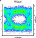


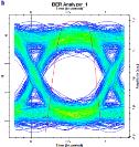
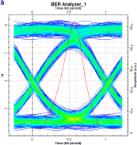
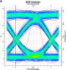
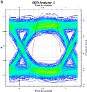
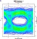
The link length is varied with a propagation loss of 0.18 dB/km at 1550 nm to observe the performance of the MDM system across the C-band. Before demultiplexing, the optical signal is selected using a sample selector. The demultiplexed outputs are detected directly with six-pin photodetectors with -18 dBm receiver sensitivity of. A low pass filter (LPF) is applied to each of the photodetector outputs. The cut-off frequency of the LPFs is set to 0.75 x (symbol rate). The performance of the link is analyzed by obtaining the bit-error-rate (BER), received power, and maximum Q-factor at 1550 nm over a length of 50 km as shown in Table 5. Figure 8 depicts the variation of BER interms of link length. The range of BER over a length of 10 to 50 km is in the range of 10 39 (LP21 at 10 km) to 10 9 (LP01 and LP51 at 50 km) at 1550 nm. The modes with less coupling exhibit good BER performance. As the link length increases due to accumulated attenuation in the direction of propagation the BER performance is reduced with that of the received power. All the spatial channels exhibit acceptable BER performance over the link length of 50 km without the use of EDFA. As demonstrated in the eye diagram of each spatial channel in Table 5, the ring-core FMF may broadcast six modes with an acceptable minimum BER of 10 9 for telecommunication applications. Table 6 compares the suggested ring-core FMF with the literature.


Inverse modeling of few-mode fiber for high-speed optical communication networks (Bhagyalaxmi


For the first time to our knowledge, we have proven the inverse modeling of ring-core FMFs using ML-based regression models in this work. For inverse modeling, the decision tree for multi-output regression shows great accuracy with a correlation coefficient of 99.5%, minimum relative error in the range of 10 3 to 10 4 The profile parameters of the desired ring-core FMF to guide six modes with large mode separation are demonstrated for the establishment of a 50 km weakly coupled MDM system. The design parameters of the proposed fiber are predicted for guiding 5, 6, 10 modes with min (����eff) in the range of 1.5×10 3 to 3.5×10 3 . The predicted parameters for guiding six-LP modes with mode degeneracy exhibit large-mode-area, low bending loss, zero dispersion slope for LP01 mode, whereas for the higher-order modes it ranges from 3 to 3ps/nm km As the azimuthal mode order of ring-core FMFs increases, coupling between adjacent mode groups decreases and makes the proposed ring-core FMF the best candidate for weakly coupled next-generation optical networks using mode-multiplexing. It can send 10 Gbit/s OOK signals per channel and receive them via direct detection with a minimum BER of 10 9 over a 50 km C-band link. The data rate may be enhanced by choosing suitable design parameters and can be verified in the future.
[1] E. B. Desurvire, “Capacity demand and technology challenges for lightwave systems in the next two decades,” Journal of Lightwave Technology, vol. 24, no. 12, pp. 4697-4710, 2006, doi: 10.1109/JLT.2006.885772.
[2] R. -J. Essiambre, G. Kramer, P. J. Winzer, G. J. Foschini, and B. Goebel, “Capacity limits of optical fiber networks,” Journal of Lightwave Technology, vol. 28, no. 4, pp. 662-701, 2010, doi: 10.1109/JLT.2009.2039464.
[3] R. Ramaswami, K. N. Sivarajan, and G. H. Sasaki, Optical networks: a practical perspective, Burlington, USA: Morgan Kaufmann, 3rd Edition, 2009 [Online] Available: http://www.cesarkallas.net/arquivos/faculdade-pos/TP319-redesopticas/Optical-Networks-3nd.pdf
[4] L. Jiang et al., “Trading off security and practicability to explore high-speed and long-haul chaotic optical communication,” Optics Express, vol. 29, no. 8, pp. 12750-12762, 2021, doi: 10.1364/OE.423098.
[5] Y. Awaji, “Review of space-division multiplexing technologies in optical communications,” IEICE Transactions on Communications, vol. 102, pp. 1-16, 2019, doi: 10.1587/transcom.2017EBI0002.
[6] G. Li, N. Bai, N. Zhao, and C. Xia, “Space-division multiplexing: the next frontier in optical communication,” Advances in Optics and Photonics, vol. 6, no. 4, pp. 413-487, 2014, doi: 10.1364/AOP.6.000413.
[7] D. J. Richardson, J. M. Fini, and L. E. Nelson, “Space-division multiplexing in optical fibres,” Nature Photonics, vol. 7, pp. 354-362, 2013, doi: 10.1038/nphoton.2013.94.
[8] Z. Yang, W. Yu, G. Peng, Y. Liu, and L. Zhang, “Recent Progress on Novel DSP Techniques for Mode Division Multiplexing Systems: A Review,” Applied Sciences, vol. 11, no. 4, 2021, doi: 10.3390/app11041363.
[9] A. K. Memon and K. X. Chen, “Recent advances in mode converters for a mode division multiplex transmission system,” OptoElectronics Review, vol. 29, pp. 13-32, 2021, doi: 10.24425/opelre.2021.135825.
[10] Y. Su, Y. He, H. Chen, X. Li, and G. Li, “Perspective on mode-division multiplexing,” Applied Physics Letters, vol. 118, no. 20, 2021, doi: 10.1063/5.0046071.
[11] J. Lataoui, A. Rjeb, N. Jaba, H. Fathallah, and M. Machhout, “Multicore raised cosine fibers for next generation space division multiplexing systems,” Optical Fiber Technology, vol. 68, 2022, doi: 10.1016/j.yofte.2021.102777.
[12] Y. Miyamoto, K. Shibahara, T. Mizuno and T. Kobayashi, “Mode-Division Multiplexing Systems for High-Capacity Optical Transport Network,” 2019 Optical Fiber Communications Conference and Exhibition (OFC), 2019, pp. 1-3 [Online] Available: https://ieeexplore.ieee.org/document/8696375
[13] S. Ö. Arik, D. Askarov, and J. M. Kahn, “Effect of Mode Coupling on Signal Processing Complexity in Mode-Division Multiplexing,” in Journal of Lightwave Technology, vol. 31, no. 3, pp. 423-431, 2013, doi: 10.1109/JLT.2012.2234083.
[14] K. -P. Ho and J. M. Kahn, “Statistics of Group Delays in Multimode Fiber With Strong Mode Coupling,” in Journal of Lightwave Technology, vol. 29, no. 21, pp. 3119-3128, 2011, doi: 10.1109/JLT.2011.2165316.
[15] G. Milione et al., “MIMO-less space division multiplexing with elliptical core optical fibers,” in Optical Fiber Communication Conference, 2017, doi: 10.1364/OFC.2017.Tu2J.1.
[16] Y. Su et al., “Design of solid-core Bragg few-mode fiber for short-reach MDM networks in O+ C+ L band,” Optics Communications, vol. 461, 2020, doi: 10.1016/j.optcom.2020.125245.
[17] S. Chen, Y. Tong, and H. Tian, “Eight-mode ring-core few-mode fiber using cross-arranged different-material-filling side holes,” Applied Optics, vol. 59, no. 15, pp. 4634-4641, 2020, doi: 10.1364/AO.392666
[18] A. Corsi, J. H. Chang, R. Wang, L. Wang, L. A. Rusch, and S. LaRochelle, “Highly elliptical core fiber with stress-induced birefringence for mode multiplexing,” Optics Letters, vol. 45, no. 10, pp. 2822-2825, 2020, doi: 10.1364/OL.387751.
[19] H. Chen, Y. Chen, J. Wang, H. Lu, L. Feng, and W. Song, “Octagonal polarization-maintaining supermode fiber for mode division multiplexing system,” Optics Communications,vol. 510, 2022, doi: 10.1016/j.optcom.2021.127897.
[20] D. Ge et al., “A 6-LP-mode ultralow-modal-crosstalk double-ring-core FMF for weakly-coupled MDM transmission,” Optics Communications, vol. 451, pp. 97-103, 2019, doi: 10.1016/j.optcom.2019.06.015.
[21] J. Liu et al., “Mode division multiplexing based on ring core optical fibers,” IEEE Journal of Quantum Electronics, vol. 54, no. 5, pp. 1-18, 2018, doi: 10.1109/JQE.2018.2864561.
[22] F. Feng et al., “All-optical mode-group multiplexed transmission over a graded-index ring-core fiber with single radial mode,” Optics Express, vol. 25, no. 12, pp. 13773-13781, 2017, doi: 10.1364/OE.25.013773.
[23] D. Ge et al., “Design of a Weakly-Coupled Ring-Core FMF and Demonstration of 6-mode 10-km IM/DD Transmission,” 2018 Optical Fiber Communications Conference and Exposition (OFC), 2018, pp. 1-3 [Online] Available: https://ieeexplore.ieee.org/document/8386197
[24] B. Behera, S. K. Varshney, and M. N. Mohanty, “Design of ultra-dispersion flattened M-type few-mode fiber for weakly-coupled mode division multiplexing transmission,” Optik, vol. 260, 2022, doi: 10.1016/j.ijleo.2022.169040.
[25] J. Han, Y. Li and J. Zhang, “Design of An Improved Radially Single-Mode and Azimuthally Multimode Ring-Core Fiber for Mode-Division Multiplexing Systems,” 2018 Asia Communications and Photonics Conference (ACP), 2018, pp. 1-3, doi: 10.1109/ACP.2018.8595836.
[26] L. Shen et al., “Design, Fabrication and Measurement of a Novel Ultra Low Loss 6-LP-Mode Fiber,” 2018 IEEE 3rd Optoelectronics Global Conference (OGC), 2018, pp. 90-93, doi: 10.1109/OGC.2018.8529882.
[27] Y. Jung et al., “Low-Loss 25.3 km Few-Mode Ring-Core Fiber for Mode-Division Multiplexed Transmission,” Journal of Lightwave Technology, vol. 35, no. 8, pp. 1363-1368, 2017, doi: 10.1109/JLT.2017.2658343.
[28] J. H. Chang, A. Corsi, L. A. Rusch and S. LaRochelle, “Design Analysis of OAM Fibers Using Particle Swarm Optimization Algorithm,” in Journal of Lightwave Technology, vol. 38, no. 4, pp. 846-856, 2020, doi: 10.1109/JLT.2019.2945870.
[29] L. Rosa and K. Saitoh, “Optimization of large-mode-area tapered-index multi-core fibers with high differential mode bending loss for Ytterbium-doped fiber applications,” 36th European Conference and Exhibition on Optical Communication, 2010, pp. 1-3, doi: 10.1109/ECOC.2010.5621181.
[30] Z. He et al., “Machine learning aided inverse design for few-mode fiber weak-coupling optimization,” Optics Express, vol. 28, no. 15, pp. 21668-21681, 2020, doi: 10.1364/OE.398157.
[31] B. Behera and M. N. Mohanty, “Design of Bend-Limited Large-Mode Area Dispersion Shifted Few-Mode Fiber for Fast Communication,” 2019 International Conference on Applied Machine Learning (ICAML), 2019, pp. 277-281, doi: 10.1109/ICAML48257.2019.00058.
[32] R. I. Sabitu, N. Dong-Nhat, and A. Malekmohammadi, “High dispersion four-mode fiber for mode-division multiplexing systems,” Optik, vol. 181, pp. 1-12, 2019, doi: 10.1016/j.ijleo.2018.12.008.
[33] M. S. Ab-Rahman, F. M. Shaltami, I. -S. Hwang, and A. A. Swedan, “Analysis of 10 Gbps SOA-based optical network unit with low seeding power that uses feedback seeding scheme,” Optik, vol. 183, pp. 602-611, 2019, doi: 10.1016/j.ijleo.2019.02.071.
[34] Y. -Y. Song and L. Ying, “Decision tree methods: applications for classification and prediction,” Shanghaiarchivesofpsychiatry, vol. 27, no.2,pp.130-135,2015.[Online]. Available:https://www.ncbi.nlm.nih.gov/pmc/articles/PMC4466856/pdf/sap-27-02-130.pdf
[35] B. Behera, S. K. Varshney, and M. N. Mohanty, “Structure for fast photonic medium on application of SDM communication using SiO2 doped with GeO2, and F Materials,” IET Nanodielectrics, vol. 4, no. 3, pp. 107-120, 2021, doi: 10.1049/nde2.12009.
[36] M. S. A. Bhuiyan and H. M. M. R. Mondal, “Profile optimization of dispersion shifted fiber based on optifiber design, simulation and performance analysis,” in 2013 International Conference on Informatics, Electronics and Vision (ICIEV), 2013. [Online]. Available: https://www.researchgate.net/publication/261268225_Profile_optimization_of_dispersion_shifted_fiber_based_on_optifiber_design_s imulation_and_performance_analysis

Bhagyalaxmi Behera is presently working as a Assistant Professor in the Department of Electronics and Communication Engineering (along with pusuing her Ph.D.), Institute of Technical Education and Research, Siksha ‘O’ Anusandhan (Deemed to be University), Bhubaneswar, Odisha, India. Her areas of research interest include optical communication, fiber optics and photonics, optical devices for next generation communication, machine learning based design approaches for fibers. She can be contacted at email: bhagyaiter@gmail.com.

Shailendra Kumar Varshney is presently working as a Associate Professor in the Department of Electronics and Electrical Communication Engineering, IIT, Khargpur, India. He has approximately 15 years of teaching experience. He holds a Ph.D. in Applied Physics, from University of Delhi. His areas of research interest include fiber optics and photonics, micro photonics, nonlinear photonics, quantum photonics, optical wireless communication, and quantum photonic. He can be contacted at email: skvarshney.iitkgp@gmail.com.
Mihir Narayan Mohanty is presently working as a Professor at the Department of Electronics and Communication Engineering, Institute of Technical Education and Research, Siksha ‘O’ Anusandhan (Deemed to be University), Bhubaneswar, Odisha, India. He has published over 400 papers in international/national journals and conferences along with approximately 25 years of teaching experience. He holds a Ph.D. in Applied Signal Processing. His areas of research interest include applied signal and image processing, digital signal/image processing, biomedical signal processing, microwave communication engineering, and speech processing. He can be contacted at email: mihir.n.mohanty@gmail.com.
