


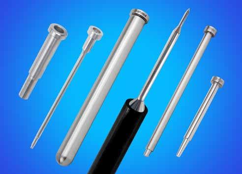
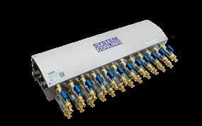
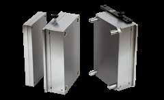
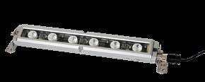
SOLUTIONS FOR BETTER PERFORMING TOOLS CATALOG VERSION 15 RECENTLY ADDED PRODUCTS Customer Service 1-800-269-6653 | 1-847-487-1000 www.procomps.com ProFile Asset Tracking and Monitoring Section F Toolroom Innovations Section M Black Nitride Greaseless Components Sections A & B Side Action Components Section G Jumper Baffles Reverse Flow Baffles Section E Bar Locks Top Machine Style Section C
ABOUT PROGRESSIVE
Progressive’s roots are in mold building and mold design, so rather than function simply as a reseller, our team engineers, develops, and supports every item and service within our product range:

PRECISION STANDARDS
Tight Tolerances Maintained. Proven Performance Achieved

TECHNOLOGY AND SUPPORT
Invented Mold Monitoring. Advancing for Growing Needs.
PROGRESSIVE’S COMMITMENT
With a foundation in the mold business, we feel a responsibility to provide every customer with best-in-class products and service levels:
• Products that meet expectations for quality, value, and performance.
• Knowledgeable and helpful Customer Service and Technical Support staff.
• Prompt resolution to order issues and billing questions. If there is any way in which we can serve your needs better, contact us or any Progressive Team Member.
SERVICE CAPABILITY
MOLD-READY™ COMPONENTS
Made-To-Order Components. Proprietary Treatments Available.
Wherever your tooling is built or run, Progressive Components is positioned nearby:

• Stocking locations in Illinois, California, and South Carolina.
• Tech and service support in Singapore, Portugal, England, Germany, Mexico, and the USA.


We serve a global industry with borderless Account Management that operates as one integrated network.
 Don Starkey, Chairman don.starkey@procomps.com
Glenn Starkey, President glenn.starkey@procomps.com
Don Starkey, Chairman don.starkey@procomps.com
Glenn Starkey, President glenn.starkey@procomps.com
Regional Headquarters Stocking Locations Distribution Partners
1 electrical components Cables Hot Sprue Bushings KO Switches Recessed Connectors Plate Position Switches Thermocouples Wire Channels alignment locks Bar Locks & Guides Black Nitride Side Locks Cavity Interlocks Guide Locks Needle Bearing Locks Shuttle Mold Locks Side Locks Taper Locks Taper Bar Locks Top Locks X-Series Locks lifters undercut release C-Series Lifters FlexiCores Guides & Keys ModuLifters Spherical Bushings UniLifters Versa-Lifters rapid tooling inserts Clamps Frames Inserts RTI Pins & Bushings RTI Support Pillars T-Handles toolroom innovations Mold Light Bar Fin Tip Nozzles Nozzle Caddie Mold Finish Guide Rhino Foot Rhino Toes Status Tags Synthetic Mold Grease Toolroom Bench slide components camactions Angle Pins Angle Pin Holders CamActions CamAction Pins/Inserts Center Guides L-Gibs Square Gibs SRT Slide Retainers Urethane Retainers Wear Strips Wear Plates mold monitoring Asset Tags & Plates CounterView CV/CVe Cover Plates CVe Monitor CVe OnDemand Insulator Block/Bracket MoldTrax ProFile Real-Time ProFile Asset Mgt. System Cooling System Cooling Test Rig collapsible cores expandable cavities DT Series C-Cores Expandable Cavities Grinding Rings MiniCores Retention Sleeves RT Series C-Cores plate sequence control Friction Pullers Plate Latch Locks Plate Accelerators Plate Retainers Roller Pullers StacKit date marking air valves Air Poppets Air Valves Date Stamps Date Plugs Recycle Inserts Retro/Indexable Plugs mold base components Black Nitride Leader Pins & Bushings Extended Sprues Front Loading Pins Guided Ej Bushings Guided Ejector Pins Guided Support Pillars Leader Pins Locating Rings/Shims PKO Extensions Puller Pins & Bushings Shoulder Bushings Spacers Springs Sprue Bushings Straight Bushings Stripper Bolts & Bushings Support Columns Support Pillars Stop Discs & Pins Tubular Dowels ejector pins core pins sleeves Black Nitride Ej Pins Blade Ejectors Core Pins & Retainers Ejector Pins Ejector Sleeves Metric Pins/Sleeves/ Blades Mold-Ready Pins Return Pins Sleeve Extensions Thin Wall Sleeves TI Pins UltraPins cooling products Baffles (NPT/BSPT) Bubbler Base Cascades Clamps & Tape Connector Plugs Diverting Rods & Plugs Elbows Extension Plugs Hex & Piston Tubes Hose Hose Barbs Inlet Cascade Fittings Misc Brass Fittings O-Rings Safety Clips Threadless Plugs Tubes Water Blockers Water Jumpers
2 Adjustable Hex Nipples E-28 Air Valves & Poppets D-13 Angle Pins G-23 Angle Pin Holders G-24 Asset Tags & Plates F-7 Baffles E-2 Baffles: Jumper E-4 Baffles: Reverse Flow E-5 Bar Locks: Inserted C-9 Bar Locks: Side Machine C-4 Bar Locks: Side Machine Guides C-5 Bar Locks: Top Machine Bars & Guides C-6 Bar Locks: X-Style C-7 Black Nitride Ejector Pins A-1 Black Nitride Leader Pins B-10 Black Nitride Bushings B-11 Black Nitride Side Lock C-22 Blade Ejectors: DIN A-11 Blade Ejectors: Inch A-10 Bubbler Base E-12 Bushings: Guided Ejector B-14 Bushings: Shoulder B-12 Bushings: Straight B-13 CamActions® G-2 Cascade: Hex Key, Compact E-10 Cascade: High Flow E-7 Cascade: Nipple Type E-6 Cascade: Quick Coupler E-11 Cascade: Rear Load Quick Coupler E-9 Cascade: Rear Loading Nipple E-8 Cavity Interlocks: Flat Series C-16 Cavity Interlocks: Round Series C-17 Center Guides G-19 Collapsible Cores: DT Series I-1 Collapsible Cores: RT Series I-9 Combination Hose Inserts E-38 Connector Plugs E-24 Connector Plugs: Keyed E-26 Core Pin Retainers A-18 Core Pins A-12 CounterView: Attachment Block F-10 CounterView: R-Series F-9 CounterView: S-Series F-8 Cover Plugs, Clamps & Tape E-39 CounterView/CVe Cover Plates F-12 CVe Monitor® F-1 CVe OnDemand® F-3 Date Plugs: Replacements D-9 Date Stamps: 20 Series D-5 Date Stamps: CH Series D-6 Date Stamps: Compact Locking D-2 Date Stamps: D (Deep) Series D-5 Date Stamps: FD Series D-7 Date Stamps: LG Series D-11 Date Stamps: Locking Series D-1 Date Stamps: MicroDaters D-10 Date Stamps: Multi-Daters D-8 Date Stamps: RF Series D-4 Date Stamps: Tapered Series D-3 Diverting Rods & Plugs E-33 Ejector Accelerators J-12 Ejector Pins: Metric DIN A-4 Ejector Pins: Inch A-2 Ejector Pins: Metric JIS A-6 Ejector Sleeves: Inch A-14 Ejector Sleeves: Metric DIN A-15 Ejector Sleeves: Thin Wall (Inch) A-16 Elbows: Hex Key E-29 Expandable Cavities I-12 Extended Sprue Bushings B-4 Extension Elbows E-36 Extension Plugs E-21 Extension Plugs: Keyed Connect E-23 FlexiCore® System H-18 Friction Pullers J-14 Front Load Pins & Bushings B-16 Front Loading LP/B Guide Blocks B-17 Grease: Synthetic M-8 Guide Locks: Z-Series C-14 Guided Ejector Pins B-8 Hex Elbows: Female & Male E-36 Hex Key Extension Pipes E-28 Hose Barbs & Splicers E-37 Hose: Push-Lok® E-30 Hot Sprue Bushings K-8 Inlet Cascades E-13 Insulator Block: External Mount F-10 Insulator Block: Retrofit Bracket F-11 Leader Pins: Inch B-6 Leader Pins: Metric DIN B-7 Leader Pins: Shoulder Style B-9 L-Gibs G-22 Lifter Guides H-10 Lifter Head Key H-11 Locating Rings B-2 Locating Ring Shims B-3 MiniLifter® Series H-2 ModuLifter® System H-12 Mold Finish Guide M-7 Mold Light Bar M-8 MoldTrax F-13 Nozzle Caddie & Wrench M-3 Nozzles: Fin Tip M-2 O-Rings: Core Diameter Seal E-18 O-Rings: Core Face Seal E-19 O-Rings: Face Seal E-17 Patch Cables K-6 Pipe Check E-1 Pipe Nipples E-30 PKO Extensions & Pucks B-30 Plate Accelerators J-13 Plate Latch Locks: Cam Sequencing J-1 Plate Latch Locks: Can Block J-5 Plate Retainers J-8 Plugs: Pipe E-20 Plugs: Threadless E-32 Plugs: Water Blocker™ E-31 ProFile® Asset Management System F-6 ProFile® : Real-Time Monitoring F-4 Puller Pins & Bushings B-5 Recessed Connectors K-6 Rectangular Taper Bar Locks C-15 Recycle Inserts D-12 Reducers & Couplings E-41 Remote Validation Kit F-4 Return Pins A-19 RhinoFoot™ M-1 RhinoToes M-1 Roller Pullers J-7 RTI® 08/09 Series L-2 RTI® 08/10 Series L-5 RTI® 10/14 Series L-11 RTI® 84/90 Series L-8 RTI® Complete L-14 RTI® Complete Cavity & Core Inserts L-15 RTI® Frame Clamps L-22 RTI® Frame Sprue Bushings L-21 RTI® Frames L-16 RTI® Pins & Bushings L-20 RTI® Straps L-22 RTI® Support Pillars L-21 RTI® T-Handles L-22 Shuttle Mold Sets C-11 Side Locks: Graphite Plugged C-24 Side Locks: Needle Bearing C-20 Side Locks: Steel C-23 Side Locks: Z-Series C-10 Side Locks: X-Style, Z-Series C-11 Sleeve Extensions / Blanks A-17 Socket Connectors E-25 Socket Connectors: Keyed Connect E-27 Socket Connector Safety Clips E-27 Spacers B-29 Spanner Wrench B-15 Spherical Bushings H-9 Springs B-23 Springs: Urethane B-22 Sprue Bushings B-1 SRT Bases & Bushings G-16 SRT Slide Retainers & Cleats G-14 StacKit System J-15 Status Tags M-6 Stop Discs & Pins B-29 Stripper Bolt Bushings B-27 Stripper Bolts B-26 Square Gibs G-18 Support Columns B-20 Support Pillars: Counterbored B-18 Support Pillars: Guided B-21 Support Pillars: Stainless B-19 Support Pillars: Threaded B-18 Switch: Extension Block Assembly K-6 Switch: External Mount K-5 Switch: KO™ K-1 Switch: KO™ Single/Dual Ejector K-2 Switch: Plate Position K-4 Switch: Side Action K-4 System Cooling™ F-14 System Cooling™ Test Rig F-17 Taper Locks: Counterbored C-18 Taper Locks & Plates C-15 Tees & Elbows E-40 Thermocouples K-7 TI™ Pins A-13 Toolroom Bench M-4 Top Locks: Internal C-12 Top Locks: Needle Bearing C-20 Top Locks: Z-Series C-13 Tubes: High Flow & Hex Series E-14 Tubes: Piston & Brass E-16 Tubular Dowels B-28 Two-Stage Ejectors J-10 UltraPins® A-8 UniLifter® System H-1 Versa-Lifter™ System H-7 Water Jumpers: Push-Lok® Series E-34 Water Jumpers: Swivel Type E-35 Wear Plates: Bronze G-22 Wear Strips G-20 Wear Plates G-21 Wire Channel Inserts K-7 Product Description Page Product Description Page Product Description Page
MOLD


3
CORE PINS SLEEVES Black Nitride Ejector Pins Ejector Pins: Straight Inch Ejector Pins: Shoulder Ejector Pins: Straight DIN Catalog # Prefix Prefix: EP Prefix: EP Prefix: EP Prefix: EPD Catalog Page Page: A-1 Page: A-2 Page: A-3 Page: A-4 Ejector Pins: Shld. DIN Ejector Pins: Straight JIS Ejector Pins: Shoulder JIS UltraPins: Straight UltraPins: Shoulder Prefix: EPD Prefix: EPJ Prefix: EPJ Prefix: EPL Prefix: EPL Page: A-5 Page: A-6 Page: A-7 Page: A-8 Page: A-9 Blade Ejectors: Inch Blade Ejectors: DIN Core Pins TI Pins Ejector Sleeves: Inch Prefix: BE Prefix: CP Prefix: TI Prefix: ES Page: A-10 Page: A-12 Page: A-13 Page: A-14 Ejector Sleeves: DIN Thin Wall Sleeves Sleeve Extensions Core Pin Retainers Return Pins Prefix: ESD Prefix: ESTW Prefix: SXT Prefix: CPR Prefix: RP Page: A-15 Page: A-16 Page: A-17 Page: A-19
EJECTOR PINS
Sprue Bushings Locating Rings & Shims Extended Sprues Catalog # Prefix Prefix: SPR Prefix: LR Prefix: ESB, RX Catalog Page Page: B-1 Page: B-2 Leader Pins: Inch Leader Pins: DIN Leader Pins: Shoulder Black Nitride Leader Pins Prefix: LP Prefix: SLP Prefix: LP Page: B-6 Page: B-10 Black Nitride
Bushings:
Bushings:
Guided Ejector Bushings Front Load Pins/Bushings Prefix: STL, GEB Prefix: SAB, SHB, SGP, STL Prefix: STB, STGP Prefix: GEB, GGP, GQC Prefix: FLPB Page: B-11 Page: B-12 & B-13 Page: B-13 Page: B-14 & B-15 Page: B-16
BASE COMPONENTS
Bushings
Shoulder
Straight
Guide Blocks Support Pillars/Columns Guided Support Pillars
GBK Prefix: SP, SPH
GESP
Urethane Springs Springs

MS, HS
B-23 - B-25 Stripper Bolts Stripper Bolt Bushings Tubular Dowels Stop Discs/Pins/Spacers PKO Extensions & Pucks

B-17
SBLT
ALIGNMENT LOCKS
SBB
TD Prefix: SD, STP, SPC
PH, PKP
Locks: Side Machine Bar Locks: Top Machine Bar Locks: X-Style Bar Locks: Inserted


# Prefix Prefix: BLB, BLG
BLBT, BLGT
BLBX
BLN, BLS
C-9
Locks Side Locks: X-Style Top Locks: Internal Top Locks Guide Locks
SL, SLC, SLM
Rect. Taper Bar Locks
TL, TLM
GL, GLM
4
Prefix:
Prefix:
Prefix:
Page:
Page:
Page:
Prefix:
Prefix:
Prefix:
Page:
Page:
Page: B-28 Page:
Page: B-30
Prefix: US
B-21
Prefix:
B-26
B-27
B-29
Bar
Catalog
Prefix:
Prefix:
Prefix:
Catalog
Page:
Page:
Page:
Page:
Prefix:
Prefix:
Prefix:
Page:
Page:
Page:
Page:
Page
C-4 & C-5
C-6
C-7
Side
Prefix: SLX
C-10
C-11
C-12
C-14
Cavity Interlocks: Flat Cavity Interlocks: Round Taper Locks: C’Bored Taper Locks & Plates Prefix: MTBL, FTBL Prefix: CF, CFM Prefix: CRS, CRSM Prefix: TLC Prefix: MTL, FTL, TLP Page: C-15 Page: C-16 Page: C-19 Needle Bearing Locks Black Nitride Side Lock Side Locks: Steel Side Locks: Graphite Prefix: SLR, SLRM, TLR Prefix: SL Prefix: SLS, SLMS Prefix: SLPM Page: C-20 & C-21 Page: C-22 Page: C-23 Page: C-24 DATE MARKING, AIR VALVES Locking Detent Series Tapered Series RF Series 20 Series Catalog # Prefix Prefix: DN, DTN Prefix: DTPR Prefix: DF Prefix: DL Catalog Page Page: D-1 & D-2 Page: D-3 Page: D-4 Page: D-5 D Series CH Series FD Series Multi-Daters Retro & Indexable Plugs Prefix: DC, Suffix: -D Prefix: DC Prefix: DFD Prefix: DMD Prefix: DP, DXP Page: D-5 Page: D-6 Page: D-7 Page: D-8 Page: D-9
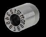
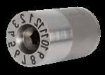
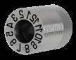
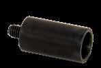
MicroDaters LG Series Recycle Inserts Air Valves Air Poppets
Prefix: MD Prefix: DLB, DLS Prefix: RI, RIS Prefix: AV Prefix: APV
D-10
COOLING PRODUCTS
D-11 Page: D-12
D-14
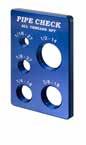
Pipe Check Baffles Jumper Baffles Reverse Flow Baffles Catalog # Prefix Prefix: PC Prefix: SB, TB Prefix: JBA Prefix: RFB Page: E-2 & E-3
Cascade: Nipple Type Cascade: High Flow Cascade: Rear Load Cascade: RL Quick Cplr Cascade: Hex Key/Comp. Prefix: NC Prefix: HFC Prefix: RLN Prefix: RLQC Prefix: HKC, CC
E-8
Cascade: Quick Coupler Bubbler Base Inlet Cascade Metric Tubes: High Flow Tubes: High Flow, Hex Prefix: QC Prefix: BBL Prefix: CF Prefix: HFTM, HEXM Prefix: HFT, HEXT

E-15
Tubes: Piston, Brass O-Rings Pipe Plugs Extension Plugs Connector Plugs
Prefix: PT, T Prefix: OR Prefix: BR, ST, SS Prefix: Numeral Prefix: Numeral
E-16 Page: E-17 Page: E-21 - E-23 Page: E-24
Socket Connectors Connector Plugs: Keyed Socket Conn: Keyed Safety Clips Adjustable Hex Nipples


Prefix: SC Prefix: Numeral, Suffix: -K Prefix: SC, Suffix: -K Prefix: SC Prefix: APN Page: E-25 Page: E-26 Page: E-27 Page: E-28
Hex Key Ext Pipes Elbows: Hex Key


Pipe Nipples Push-Lok Hose Plugs: Water Blockers

Prefix: HKEPN Prefix: HK, HKEE, HKL Prefix: BPN, GPN Prefix: WJH Prefix: WB Page: E-28 Page: E-29 Page: E-30
Page: E-30
Plugs: Threadless Diverting Rods & Plugs Water Jumpers
Water Jumpers: Swivel Elbows: Hex, Extension
Prefix: TWP, TAP, TDP Prefix: D, DR Prefix: WJ Prefix: WJ Prefix: HELS, HELB Page: E-32 Page: E-33 Page: E-34 Page: E-35 Page: E-36
5
Page:
Page:
Page:
Page: E-5
Page:
E-6 Page: E-7 Page:
Page: E-9 Page: E-10
Page:
Page:
Page:
Page:
E-11
E-12
E-14
Page:


6 Hose Barbs & Splicers Comb. Hose Inserts Clamps & Tape Tees & Elbows Reducers & Couplings Prefix: MB, FB, HS Prefix: Numeral Prefix: CP, HC, TT Prefix: T, MT, ELS, EL, ELA Prefix: RB, MR, C, HN Page: E-37 Page: E-38 Page: E-39 Page: E-40 Page: E-41 MOLD MONITORING CVe Monitor CVe OnDemand ProFile: Real-Time Monitoring Remote Validation Kit Catalog # Prefix Prefix: CVE Prefix: RVK Catalog Page Page: F-1 Page: F-3 Page: F-4 Page: F-4 AST000000456 CVeMonitor.com AST123456789 Custom Text 1 Custom Text 2 Custom Text 3 Custom Text 4 AST000001234 ProFile-System.com AST00006789 CVeMonitor.com 000001 AST000000123 ProFile-System.com Button Head Cap Screws ProFile: Asset Mgt Asset Tags & Plates CounterView: S-Series CounterView: R-Series Insulator Blocks Prefix: AMTG Prefix: CVPL, CVPLHT Prefix: CVR-A, CVR-B Prefix: CV, CVMM, CVRA Page: F-6 Page: F-7 Page: F-9 Page: F-10 & F-11 CV/CVe Cover Plates Mold Trax System Cooling System Cooling Portable Cart System Cooling Test Rig Prefix: CV Prefix: SCM Prefix: SCP Prefix: SCTR Page: F-12 Page: F-13 Page: F-14 Page: F-16 Page: F-17 SLIDE COMPONENTS CAM ACTIONS CamAction 100 Series CamAction 200 Series CamAction 250 Series CamAction 300/350 Catalog # Prefix Prefix: CA, CAMM Prefix: CA, CAMM Prefix: CA, CAMM Prefix: CA, CAMM Page: G-2 Page: G-3 Page: G-4 Page: G-5 - G-8 CamAction 400 Series Slide Retainers SRT Bases & Bushings Square Gibs Center Guides Prefix: CA Prefix: SRTBA, SRTBU Prefix: SG Prefix: CG Page: G-9 Page: G-16 Page: G-18 Page: G-19 Wear Strips Wear Plates Bronze Plates & L-Gibs Angle Pins Angle Pin Holders Prefix: WS Prefix: WP Prefix: WP, LGIB Prefix: AP Prefix: APH Page: G-20 Page: G-21 Page: G-22 Page: G-23 Page: G-24 & G-25
LIFTERS
ELECTRICAL


7
UNDERCUT RELEASE UniLifters: UL-Series UniLifters: C-Series Versa-Lifter System Spherical Bushings Catalog # Prefix Prefix: CB, UC, TG Prefix: UGV, SGV, CBV Prefix: LSB Catalog Page Page: H-1 - H-4 Page: H-9 Lifter Guides Lifter Head Key ModuLifter System FlexiCore System Prefix: LG, SGV Prefix: LHK Prefix: MLB, MLC, MLR, MLH Prefix: FCA, FCR, FCDA Page: H-10 Page: H-11 Page: H-12 - H-17 Page: H-18 - H-23
CORES EXPANDABLE CAVITIES C-Cores: DT Series DT Core Sub-10mm C-Cores: RT Series Expandable Cavities Catalog # Prefix Prefix: EXCAV Prefix: S10 Prefix: CC, CCM Prefix: EXCAV Catalog Page Page: I-1 Page: I-7 Page: I-9 Page: I-12 PLATE SEQUENCE CONTROL Latch Locks: Cam Seq. Latch Locks: Cam Block Roller Pullers Plate Retainers Catalog # Prefix Prefix: PLC, PLCM Prefix: PLC, PLCM Prefix: RPL Prefix: PRT Catalog Page Page: J-1 Page: J-5 Page: J-7 Page: J-8 Two-Stage Ejectors Ejector Accelerators Plate Accelerators Friction Pullers StacKit System Prefix: PLN Prefix: EJA Prefix: ACCPM Prefix: FP Prefix: SK Page: J-10 Page: J-12 Page: J-14 Page: J-15 - J-18
COLLAPSIBLE
COMPONENTS KO Switches Plate Position Switch Side Action Switch Catalog # Prefix Prefix: SWKO Prefix: SWPPS Prefix: SWSA Catalog Page Page: K-1 & K-2 Page: K-4 Patch Cables Recessed Connectors Thermocouples Wire Channel Inserts Hot Sprue Bushings Prefix: ECCA Prefix: ECRC Prefix: TC Prefix: WC Prefix: BX Page: K-6 Page: K-6 Page: K-7 Page: K-7 Page: K-8 & K-9
RAPID TOOLING INSERTS


TOOLROOM INNOVATIONS
Progressive Components International Corporation has products that are protected by numerous patents, design patents, international patents and other patents pending. Contact Progressive Components with any inquiries regarding potential Intellectual Property concerns or violations.
Progressive Components®, ////®, ////Pro®, CADalog®, CamAction®, CounterView®, CVe®, CVe Monitor®, CVe OnDemand®, CVe Live®, KO®, PC/Mold®, ProFile®, ProComps®, ProSpec®, Rapid Tooling Insert®, RTI®, SRT®, StacKit®, ToolingDocs®, UltraPin®, UniLifter®, and ModuLifter® and are registered U.S. trademarks. Bubbler Base™, FlexiCore™, Inlet Cascades™, MicroDater™, MiniLifter™, PKO™, Puller Pins™, QC™, Roller Pullers™, TI™, Z-Series™, System Cooling™, Versa-Lifter™, Water Blocker™, Mold-Ready Components™, and the Progressive Components logo are U.S. trademarks and numerous registered and pending international trademarks are the property of Progressive Components International Corporation.
AutoCAD® and Mechanical Desktop® are registered trademarks and DXF™ is a trademark of AutoDesk, Inc.; Windows® is a trademark of Microsoft Corp.; Push-Lok® is a trademark of Parker Hannifin Corp.; PCS® is a trademark of PCS Company; CUMSA® is a trademark of CUMSA of Spain; DME® is a trademark of D-M-E Company; MoldTrax™ and MTWEB™ are trademarks of MoldTrax LLC; SolidWorks® is a registered trademark of Dassault Systèmes SolidWorks Corp and MiniCore®, C-Core®, and Ex-Cav® are registered trademarks of Roehr Tool Solutions. Rhino Foot™ and Rhino Toes™ are trademarks of Rhino Products LLC. Viton® is a registered trademark of The Chemours Company FC, LLC/DuPont and related parties. Mastip™ nozzle systems are protected by numerous registered designs, patents, and international patents pending.
©2023 Progressive Components International Corporation


Unauthorized reproduction, distribution, or display of any portion of this printed or online catalog is prohibited. Printed in USA.
8
Rapid Tooling Inserts RTI: Complete Cavity & Core Inserts Frames Catalog # Prefix Prefix: RTS, RTL, RTT Prefix: RTLP Prefix: RCI, RCIA Prefix: RTF Catalog Page Page: L-1 - L-13 Page: L-14 Page: L-16 - L-19 Pins & Bushings Frame Sprue Bushing Support Pillars Straps & T-Handle Frame Clamp Prefix: RLP, RSB. RGEB Prefix: RFS Prefix: RSP Prefix: MS, T Prefix: RFC Page: L-20 Page: L-21 Page: L-21 Page: L-22
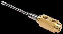
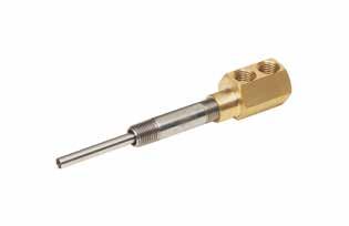
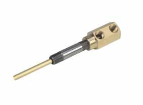
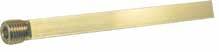
Rhino Foot™ Rhino Toes Fin Tip Nozzles Nozzle Caddie/Wrench Catalog # Prefix Prefix: RHF Prefix: RHT Prefix: NZFT Prefix: NZLCAD, NZLWR Catalog Page Page: M-1 Page: M-1 Page: M-2 Page: M-3 Toolroom Bench Status Tags Mold Finish Guide Mold Light Bar Synthetic Grease Prefix: TRB Prefix: ST Prefix: LIT Prefix: MLB Prefix: SYN Page: M-4 Page: M-6 Page: M-7 Page: M-8 Page: M-8
ORDERING INFORMATION
HOURS: Monday-Friday 7:00am-7:00pm (Central Time)
PHONE ORDERS: North America (Canada, Mexico, USA) toll-free: 1-800-269-6653 | International: 1-847-487-1000
FAX ORDERS: North America (Canada, Mexico, USA) toll-free: 1-800-462-6653 | International: 1-847-487-1027
INTERNET ORDERS: Orders may be placed via our website: www.procomps.com or via e-mail to customerservice@procomps.com.
PICK-UP ORDERS: Orders may be picked up at Regional Service Centers, subject to product availability.
WALK-IN ORDERS: Walk-in orders are accepted and processed immediately, subject to product availability.
DELIVERY
ROUTING/SHIP METHODS
• Parcel shipments will be routed via Progressive’s carrier of choice, by default. An alternate carrier may be used at the customer’s request if a valid account number is provided.
• In lieu of special instructions, packages will be routed best way per Progressive’s past experience.
• Shipments are F.O.B. shipping point for orders within the continental United States.
• Package tracking is performed at no extra charge, though carrier is responsible for delays or damage.
QUOTED DELIVERY TIME FRAME
• All quoted ship dates are based upon the date the package is anticipated to leave the specified Service Center.
CREDIT AND PAYMENT
CREDIT
• A completed credit application will be processed within 3 business days upon receipt.
• Credit levels and payment terms may be adjusted periodically based upon actual payment history and purchasing requirements.
• Orders over $10,000 may be subject to down payment requirements.
PAYMENT TERMS
Terms shall be granted in accordance with credit history and financial stability.
• Net 30 days: These terms are available only for customers whose credit/account is in good standing.
• Prepayment: Order ships upon receipt of funds.
• Special: Particular products (e.g. CVe Live/ProFile System, System Cooling, Customs and Specials, etc.) or types of orders (e.g. blanket POs) may warrant special payment terms to be specified and agreed to in writing.
PAYMENT METHODS
Payment is accepted in U.S. dollars in any form below, though actual payment history and/or financial status may limit options:
• Company Check: The cancelled check shall serve as receipt when made out and sent to: Progressive Components Intl. Corp., P.O. Box 734434, Chicago, IL 60673-4434
• Cash: Receipt will be issued to pick-up customers.
• EFT/ACH Payment: Contact Finance at billing@procomps.com for EFT/ACH routing instructions.
• Certified Funds: Money order, cashier’s check, etc.
• Wired Funds: International customers are required to make payment via wired funds. Contact the Finance Department at billing@procomps.com for routing instructions.
• Credit Cards: VISA, MasterCard, and American Express accepted.
Notes:
1. If particular payment methods are utilized due to poor credit rating, buyer is responsible for associated fees.
2. International customers: Contact Customer Service for possible foreign currency and alternate payment methods. Customers will be responsible for wire transaction fees.
3. Any reasonable costs incurred to collect past due accounts will be invoiced and due upon receipt, which may include legal expenses, collection fees and NSF charges.
WARRANTIES AND RETURNS
WARRANTIES
All products are warranted to the specifications listed in this catalog and will be accepted for full credit or replacement should any significant deviations exist. In no event will Progressive Components be liable for anticipated profits or for incidental or consequential damages. Liability is limited to the price of the item sold, and no credit for any additional charges will apply unless previously agreed to in writing by appropriate Progressive personnel.
RETURNED GOODS PROCESS
Mold Components: Standard-sized components of current specifications are eligible for return with prior approval and an issued RMA number. All items are subject to inspection before issuance of a credit for the original or replacement product. Custom items, special order items, Daters after June of the indicated year, software, and all items at or beyond 60 days from the invoice date are not eligible for return.
System Cooling: Visible damage and defects must be reported within 14 days of receipt. For any warranty claim, customer must be able to demonstrate installation and use conforms with the User and Assembly Guide provided with delivery of the system and available online. Warranty claims must be received within 12 months of invoice date.
RESTOCKING FEES
A 10% restocking fee will be applied to all approved returned goods.
CLAIMS
Notification of shipping errors within 15 days upon receipt of goods will be promptly corrected. THE FOREGOING WARRANTY IS EXCLUSIVE AND IN LIEU OF ALL OTHER WARRANTIES EXPRESSED OR IMPLIED, AS TO MERCHANTABILITY, FITNESS FOR A PARTICULAR PURPOSE, DESCRIPTION, QUALITY, PRODUCTIVENESS, OR OTHERWISE.
• Progressive Components reserves the right to make product improvements, changes, modifications or deletions to all products sold without incurring any liability.
• While every effort is made to ensure the listed dimensions and specifications in this catalog are accurate, Progressive Components does not guarantee their accuracy.
• The design guidelines and drawings are believed to be reliable, yet are provided for reference only.
• Information contained in this catalog supersedes all prior catalogs and printed sales/product information.
• Prices may be subject to change without notice. Visit www.procomps.com for all current pricing and product specifications.
9
Account Number:
Webstore User Name:
NOTES
10
EJECTOR PINS CORE PINS, SLEEVES


SECTION A
Ejector Pins: Straight Inch Ejector Pins: Shoulder Inch Ejector Pins: Straight DIN Prefix: EP Prefix: EP Prefix: EP Prefix: EPD Page: A-1 Page: A-2 Page: A-3 Page: A-4 Ejector Pins:
DIN Ejector Pins:
JIS Ejector Pins: Shoulder JIS UltraPins: Straight Prefix: EPD Prefix: EPJ Prefix: EPJ Prefix: EPL Page: A-5 Page: A-6 Page: A-7 Page: A-8 UltraPins: Shoulder Blade Ejectors: Inch Blade Ejectors: DIN Core Pins Prefix: EPL Prefix: BE Prefix: BE Prefix: CP Page: A-9 Page: A-10 Page: A-11 Page: A-12 TI Pins Ejector Sleeves: Inch Ejector Sleeves: DIN Thin Wall Sleeves Prefix: TI Prefix: ES Prefix: ESD Prefix: ESTW Page: A-13 Page: A-15 Page: A-15 Page: A-16 Sleeve Extensions Core Pin Retainers Return Pins Prefix: SXT Prefix: CPR Prefix: RP Page: A-17 Page: A-18 Page: A-19
Shoulder
Straight
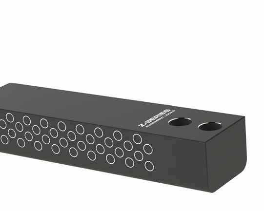
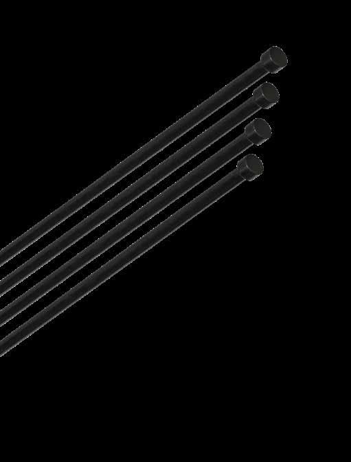
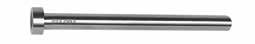
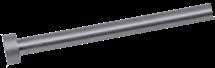
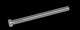
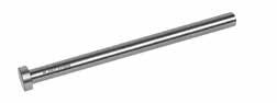
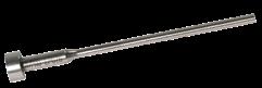
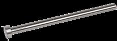
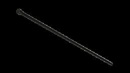
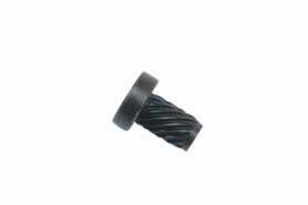
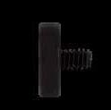
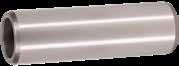
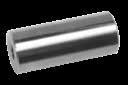
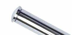
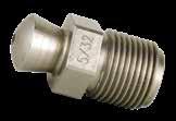
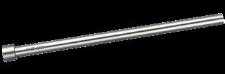
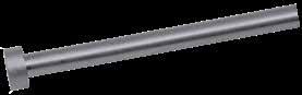
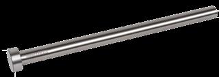
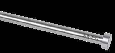
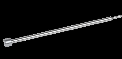
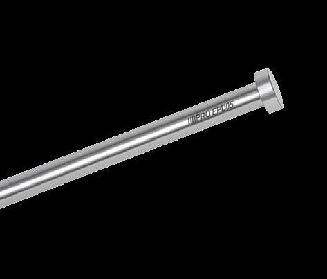
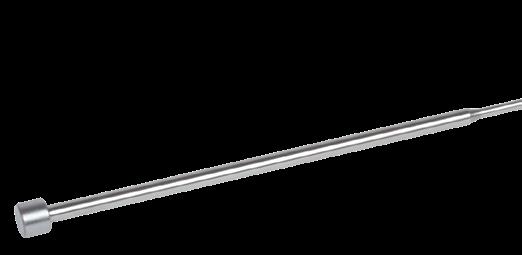
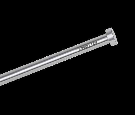
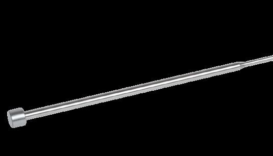
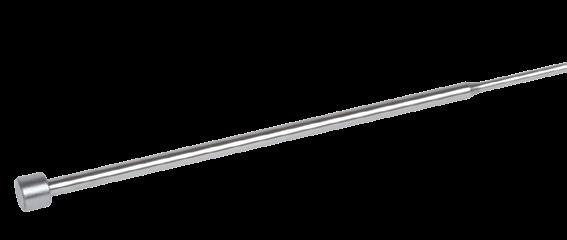
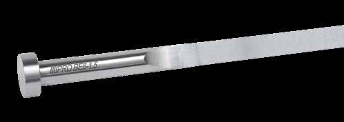
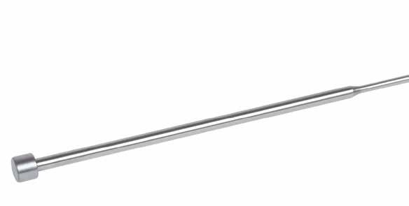
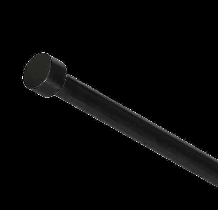
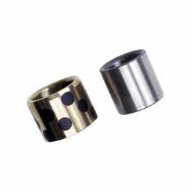
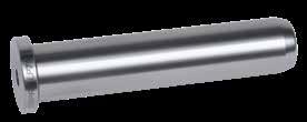
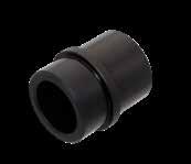
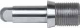
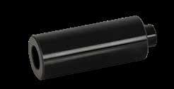
Progressive’s Black Nitride Ejector Pins are proven to provide improved performance in greaseless, medical, and die cast environments.
ALTERNATIVE CONFIGURATIONS AVAILABLE
• Any standard Ejector Pin (Inch/DIN/JIS, straight and shoulder) can be ordered with the Black Nitride treatment for better performance. To order, specify "-BN" at the end of the catalog number. Ex.
• Mold-Ready Ejector Pins can be supplied cut-to-length, keyed, and/or engraved at a standard price and delivery. Refer to page A-20 and procomps.com/mold-ready for more information.
• Made-to-order Pins can be quoted using the templates at procomps.com.
EJECTOR PINS, CORE PINS, SLEEVES A-1 H +.00 -.01 D T +.000 -.002 R .03 L+.06 -.00 68 ±2 HRC 32 ± 2 HRC 49 ± 1 HRC Ra 4 -.0003 -.0006
D H T L=10” L=14” L=18” L=25” NOMINAL DIAMETER D STANDARD D .005 OVERSIZE D STANDARD D .005 OVERSIZE D STANDARD D .005 OVERSIZE D STANDARD D .005 OVERSIZE 7/64 .25 .125 EP109L10-BN EP114L10-BN 1/8 .25 .125 EP125L10-BN EP130L10-BN 9/64 .25 .125 EP141L10-BN — EP141L14-BN EP146L14-BN 5/32 .28 .156 EP156L10-BN EP161L10-BN EP156L14-BN EP161L14-BN 3/16 .37 .187 EP187L10-BN EP192L10-BN EP187L14-BN EP192L14-BN 7/32 .40 .187 EP219L10-BN EP224L10-BN EP219L14-BN EP224L14-BN 1/4 .43 .187 EP250L10-BN EP255L10-BN EP250L18-BN EP255L18-BN EP250L25-BN 9/32 .43 .250 EP281L10-BN EP286L10-BN EP281L18-BN EP286L18-BN EP281L25-BN 5/16 .50 .250 EP312L10-BN EP317L10-BN EP312L18-BN EP317L18-BN EP312L25-BN EP317L25-BN 3/8 .62 .250 EP375L10-BN EP380L10-BN EP375L18-BN EP380L18-BN EP375L25-BN EP380L25-BN 7/16 .68 .250 EP437L10-BN EP442L10-BN EP437L18-BN EP442L18-BN EP437L25-BN EP442L25-BN 1/2 .75 .250 EP500L10-BN EP505L10-BN EP500L18-BN EP500L25-BN EP505L25-BN 9/16 .81 .250 EP562L10-BN EP562L18-BN EP562L25-BN 5/8 .87 .250 EP625L10-BN EP625L18-BN EP625L25-BN 3/4 1.00 .250 EP750L18-BN EP750L25-BN 1 1.25 .250 EP1000L18-BN EP1000L25-BN CAD insertion point M H-13 H
Surface:
Core: 48-50 HRC,
66-70 HRC S Black Nitride
EP250L10-BN.
EJECTOR PINS, CORE PINS, SLEEVES
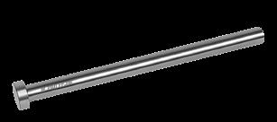
EJECTOR PINS
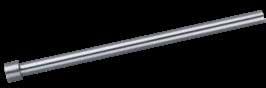
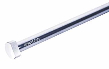
THROUGH-HARD PINS: STRAIGHT-INCH STANDARD
• To order pins with the keys tangent to the diameter, add “-K” to the end of the catalog number. Ex. EP250L10-K.
• Mold-Ready Ejector Pins can be supplied cut-to-length, keyed, and/or engraved at a standard price and delivery. Refer to page A-20 and procomps.com/mold-ready for more information.
A-2
H +.00 -.01 D T +.000 -.002 R .03 L+.06 -.00 68 ±2 HRC 32 ± 2 HRC 49 ± 1 HRC Ra 4 CAD insertion point M H-13 H Core: 48-50 HRC, Surface: 66-70 HRC D H T L=6” L=10” L=14” L=18” L=25” L=39” L=50” NOMINAL DIAMETER D STANDARD D STANDARD D .005 OVERSIZE D STANDARD D .005 OVERSIZE D STANDARD D .005 OVERSIZE D STANDARD D .005 OVERSIZE D STANDARD D STANDARD 1/32 .25 .125 EP031L6 3/64 .25 .125 EP047L6 1/16 .25 .125 EP062L6 EP062L10 5/64 .25 .125 EP078L6 EP078L10 3/32 .25 .125 EP094L6 EP094L10 7/64 .25 .125 EP109L6 EP109L10 EP114L10 1/8 .25 .125 EP125L6 EP125L10 EP130L10 EP125L14 EP130L14 EP125L18 EP125L25 9/64 .25 .125 — EP141L10 — EP141L14 EP146L14 5/32 .28 .156 EP156L6 EP156L10 EP161L10 EP156L14 EP161L14 EP156L18 EP156L25 11/64 .34 .187 EP172L10 EP172L14 EP177L14 3/16 .37 .187 EP187L6 EP187L10 EP192L10 EP187L14 EP192L14 EP187L18 EP187L25 EP187L39 EP187L50 13/64 .37 .187 EP203L10 EP203L14 EP208L14 7/32 .40 .187 EP219L6 EP219L10 EP224L10 EP219L14 EP224L14 EP219L25 15/64 .40 .187 EP234L10 — EP234L14 EP239L14 — 1/4 .43 .187 EP250L6 EP250L10 EP255L10 EP250L14 EP255L14 EP250L18 EP255L18 EP250L25 EP250L39 EP250L50 17/64 .43 .250 EP266L10 EP266L14 EP271L14 EP266L25 9/32 .43 .250 EP281L6 EP281L10 EP286L10 EP281L14 EP286L14 EP281L18 EP286L18 EP281L25 19/64 .50 .250 EP297L10 EP297L14 EP302L14 5/16 .50 .250 EP312L6 EP312L10 EP317L10 EP312L14 EP317L14 EP312L18 EP317L18 EP312L25 EP317L25 EP312L39 EP312L50 21/64 .56 .250 EP328L10 EP328L14 EP333L14 EP328L25 11/32 .56 .250 EP344L6 EP344L10 EP349L10 EP344L14 EP349L14 EP344L25 23/64 .62 .250 EP359L10 EP359L14 EP364L14 3/8 .62 .250 EP375L6 EP375L10 EP380L10 EP375L14 EP380L14 EP375L18 EP380L18 EP375L25 EP380L25 EP375L39 EP375L50 25/64 .62 .250 EP390L14 EP395L14 EP390L18 EP395L25 13/32 .68 .250 EP406L6 EP406L10 EP411L10 EP406 L14 EP411L14 EP406L18 EP406L25 27/64 .68 .250 EP422L14 EP427L14 7/16 .68 .250 EP437L6 EP437L10 EP442L10 EP437L14 EP442L14 EP437L18 EP437L25 EP437L39 EP437L50 29/64 .68 .250 EP453L14 EP458L14 15/32 .75 .250 EP469L10 EP474L10 — EP474L14 EP469L18 EP469L25 31/64 .75 .250 EP484L14 EP489L14 1/2 .75 .250 EP500L6 EP500L10 EP505L10 EP500L14 EP505L14 EP500L18 EP500L25 EP505L25 EP500L39 EP500L50 17/32 .75 .250 EP531L14 EP536L14 EP531L25 9/16 .81 .250 EP562L6 EP562L10 EP562L14 EP562L18 EP562L25 EP562L39 EP562L50 5/8 .87 .250 EP625L6 EP625L10 EP625L14 EP625L18 EP625L25 EP625L39 EP625L50 11/16 .93 .250 EP687L10 EP687L18 EP687L25 3/4 1.00 .250 EP750L6 EP750L10 EP750L14 EP750L18 EP750L25 EP750L39 EP750L50 7/8 1.12 .250 EP875L10 EP875L14 EP875L18 EP875L25 EP875L39 EP875L50 1 1.25 .250 EP1000L6 EP1000L10 EP1000L14 EP1000L18 EP1000L25 EP1000L39 EP1000L50
AVAILABLE
ALTERNATIVE CONFIGURATIONS
Ø3/64 - Ø7/16 -.0004 -.0007 Ø15/32 and Larger -.0004 -.0009 D Tolerances:
ALTERNATIVE CONFIGURATIONS AVAILABLE
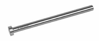
EJECTOR PINS
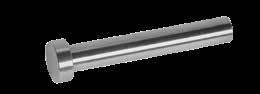
THROUGH-HARD PINS: SHOULDER-INCH STANDARD
• To order pins with the keys tangent to the diameter, add “-K” to the end of the catalog number. Ex. EP094L6-05-K.
• Mold-Ready Ejector Pins can be supplied cut-to-length, keyed, and/or engraved at a standard price and delivery. Refer to page A-20 and procomps.com/mold-ready for more information.
• Made-to-order Pins can be quoted using the templates at procomps.com.
EJECTOR PINS, CORE PINS, SLEEVES A-3
D S L=6” L=10” L=14” NOMINAL DIAMETER SHOULDER LENGTH D STANDARD D .005 OVERSIZE D STANDARD D .005 OVERSIZE D STANDARD D .005 OVERSIZE 1/32 1/2 EP031L6-05 EP036L6-05 2 EP031L6-20 EP031L10-20 EP036L10-20 3 EP031L6-30 4 EP031L6-40 3/64 1/2 EP047L6-05 EP047L10-05 EP052L10-05 2 EP047L6-20 EP047L10-20 EP052L10-20 EP047L14-20 3 EP047L10-30 4 EP047L10-40 EP052L10-40 EP047L14-40 EP052L14-40 1/16 1/2 EP062L6-05 EP062L10-05 EP067L10-05 2 EP062L6-20 EP062L10-20 EP067L10-20 EP062L14-20 3 EP062L10-30 4 EP062L10-40 EP067L10-40 EP062L14-40 EP067L14-40 5/64 1/2 EP078L6-05 EP078L10-05 EP083L10-05 2 EP078L6-20 EP078L10-20 EP083L10-20 EP078L14-20 3 EP078L10-30 4 EP078L10-40 EP083L10-40 EP078L14-40 EP083L14-40 3/32 1/2 EP094L6-05 EP094L10-05 EP099L10-05 2 EP094L6-20 EP094L10-20 EP099L10-20 EP094L14-20 3 EP094L10-30 4 EP094L10-40 EP099L10-40 EP094L14-40 EP099L14-40 7/64 1/2 EP109L6-05 EP109L10-05 EP114L10-05 2 EP109L6-20 EP109L10-20 EP114L10-20 EP109L14-20 3 EP109L10-30 4 EP109L10-40 EP114L10-40 EP109L14-40 EP114L14-40 .25 +.00 -.01 .125 D -.0004 -.0007 R .03 +.000 -.002 R .25 S L +.06 -.00 .125 +.000 -.001 68 ± 2 HRC 32 ± 2 HRC 49 ±1 HRC Ra 4 CAD insertion point M H-13 H Core: 48-50 HRC, Surface: 66-70 HRC
EJECTOR PINS, CORE PINS, SLEEVES
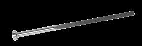
THROUGH-HARD PINS: STRAIGHT-METRIC DIN STANDARD
ALTERNATIVE CONFIGURATIONS
AVAILABLE
• To order pins with the keys tangent to the diameter, add “-K” to the end of the catalog number. Ex. EPD06L250-K.
• Mold-Ready Ejector Pins can be supplied cut-to-length, keyed, and/or engraved at a standard price and delivery. Refer to page A-20 and procomps.com/mold-ready for more information.
A-4
+0.0 -0.2 D T +0.00 -0.05 L+2.0 -0.0 g6 68 ±2 HRC 32 ±2 HRC 49 ±1 HRC R0.3 max H +0.0 -0.2 D T +0.00 -0.05 L+2.0 -0.0 g6 Stiack version R 4 z 70 ± 2 HRC 32 ± 2 HRC 42 ± 2 HRC R0.3 max Ra 4 L=160MM L=200MM L=250MM L=400MM L=630MM L=1000MM 1.2 3 1.5 EPD012L125 EPD012L160 1.5 3 1.5 EPD015L125 EPD015L160 EPD015L200 EPD015L250 1.6 3 1.5 EPD016L125 EPD016L200 EPD016L250 1.7 3 1.5 EPD017L125 EPD017L200 EPD017L250 1.8 3 1.5 EPD018L125 EPD018L200 EPD018L250 2 4 2 EPD02L125 EPD02L160 EPD02L200 EPD02L250 EPD02L400 2.2 4 2 EPD022L125 EPD022L160 EPD022L200 EPD022L250 EPD022L400 2.5 5 2 EPD025L125 EPD025L160 EPD025L200 EPD025L250 EPD025L400 2.7 5 2 EPD027L160 EPD027L250 EPD027L400 3 6 3 EPD03L125 EPD03L160 EPD03L200 EPD03L250 EPD03L400 EPD03L630 3.2 6 3 EPD032L125 EPD032L160 EPD032L200 EPD032L250 EPD032L400 3.5 7 3 EPD035L125 EPD035L160 EPD035L200 EPD035L250 EPD035L400 3.7 7 3 EPD037L160 EPD037L250 EPD037L400 4 8 3 EPD04L125 EPD04L160 EPD04L200 EPD04L250 EPD04L400 EPD04L630 4.1 8 3 EPD041L160 EPD041L250 EPD041L400 4.2 8 3 EPD042L125 EPD042L160 EPD042L200 EPD042L250 EPD042L400 4.5 8 3 EPD045L125 EPD045L160 EPD045L200 EPD045L250 EPD045L400 4.7 8 3 EPD047L125 EPD047L160 EPD047L200 EPD047L250 EPD047L400 5 10 3 EPD05L125 EPD05L160 EPD05L200 EPD05L250 EPD05L400 EPD05L630 EPD05L1000 5.2 10 3 EPD052L125 EPD052L160 EPD052L200 EPD052L250 EPD052L400 EPD052L630 5.5 10 3 EPD055L125 EPD055L160 EPD055L200 EPD055L250 EPD055L400 6 12 5 EPD06L125 EPD06L160 EPD06L200 EPD06L250 EPD06L400 EPD06L630 EPD06L1000 6.1 12 5 EPD061L160 EPD061L250 EPD061L400 6.2 12 5 EPD062L125 EPD062L160 EPD062L200 EPD062L250 EPD062L400 EPD062L630 6.5 12 5 EPD065L125 EPD065L160 EPD065L200 EPD065L250 EPD065L400 7 12 5 EPD07L125 EPD07L160 EPD07L200 EPD07L250 EPD07L400 EPD07L630 EPD07L1000 7.5 12 5 EPD075L160 EPD075L250 EPD075L400 8 14 5 EPD08L125 EPD08L160 EPD08L200 EPD08L250 EPD08L400 EPD08L630 EPD08L1000 8.2 14 5 EPD082L125 EPD082L160 EPD082L200 EPD082L250 EPD082L400 EPD082L630 8.5 14 5 EPD085L125 EPD085L160 EPD085L200 EPD085L250 EPD085L400 9 14 5 EPD09L125 EPD09L160 EPD09L200 EPD09L250 EPD09L400 9.5 14 5 EPD095L160 EPD095L250 EPD095L400 10 16 5 EPD10L125 EPD10L160 EPD10L200 EPD10L250 EPD10L400 EPD10L630 EPD10L1000 10.2 16 5 EPD102L125 EPD102L160 EPD102L200 EPD102L250 EPD102L400 10.5 16 5 EPD105L125 EPD105L160 EPD105L200 EPD105L250 EPD105L400 11 16 5 EPD11L125 EPD11L160 EPD11L200 EPD11L250 EPD11L400 12 18 7 EPD12L125 EPD12L160 EPD12L200 EPD12L250 EPD12L400 EPD12L630 EPD12L1000 12.2 18 7 EPD122L125 EPD122L160 EPD122L200 EPD122L250 EPD122L400 12.5 18 7 EPD125L125 EPD125L160 EPD125L200 EPD125L250 EPD125L400 14 22 7 EPD14L125 EPD14L160 EPD14L200 EPD14L250 EPD14L400 EPD14L630 16 22 7 EPD16L125 EPD16L160 EPD16L200 EPD16L250 EPD16L400 EPD16L630 16.2 22 7 EPD162L250 EPD162L400 EPD162L630 18 24 7 EPD18L160 EPD18L200 EPD18L250 EPD18L400 EPD18L630 20 26 8 EPD20L160 EPD20L200 EPD20L250 EPD20L400 EPD20L630 EPD20L1000 25 32 10 EPD25L160 EPD25L200 EPD25L250 EPD25L400 EPD25L630 EPD25L1000 32 40 10 EPD32L160 EPD32L200 EPD32L250 EPD32L400 EPD32L630 EPD32L1000 CAD insertion point M 1.2344 (H-13) H Core: 48-50 HRC, Surface: 66-70 HRC
ALTERNATIVE CONFIGURATIONS AVAILABLE
EJECTOR PINS
THROUGH-HARD PINS: SHOULDER-METRIC DIN STANDARD
STANDARD DIN TOLERANCES
• To order pins with the keys tangent to the diameter, add “-K” to the end of the catalog number. Ex. EPD018X3L125-50-K.
• Mold-Ready Ejector Pins can be supplied cut-to-length, keyed, and/or engraved at a standard price and delivery. Refer to page A-20 and procomps.com/mold-ready for more information.
• Made-to-order Pins can be quoted using the templates at procomps.com.
EJECTOR PINS, CORE PINS, SLEEVES A-5
H +0.0 -0.2 T S L Dg6 +0.00 -0.05 +2.0 -0.0 B +0.0 -0.1 R 10 32 ±2 HRC 49 ±1 HRC 68 ±2 HRC R 0.3 max Ra 4 NOMINAL DIAMETER (MM) SHAFT TOLERANCE Over To g6 0 3 -.002 -.008 3 6 -.004 -.012 6 10 -.005 -.014 10 18 -.006 -.017 18 30 -.007 -.020 30 50 -.009 -.025
CAD insertion point M 1.2344 (H-13) H Core: 48-50 HRC, Surface: 66-70 HRC D NOMINAL DIAMETER B H T L=125MM S=50MM L=160MM S=75MM L=200MM S=75MM 0.8 2 4 2 EPD008X2L125-50 EPD008X2L160-75 0.9 2 4 2 EPD009X2L125-50 EPD009X2L160-75 1 2 4 2 EPD01X2L125-50 EPD01X2L160-75 EPD01X2L200-75 1.1 2 4 2 EPD011X2L125-50 EPD011X2L160-75 1.2 2 4 2 EPD012X2L125-50 EPD012X2L160-75 1.3 2 4 2 EPD013X2L125-50 EPD013X2L160-75 EPD013X2L200-75 1.4 2 4 2 EPD014X2L125-50 EPD014X2L160-75 1.5 3 6 3 EPD015X3L125-50 EPD015X3L160-75 EPD015X3L200-75 1.6 3 6 3 EPD016X3L125-50 EPD016X3L160-75 EPD016X3L200-75 1.7 3 6 3 EPD017X3L160-75 EPD017X3L200-75 1.8 3 6 3 EPD018X3L125-50 EPD018X3L160-75 EPD018X3L200-75 2 3 6 3 EPD02X3L125-50 EPD02X3L160-75 EPD02X3L200-75 2.2 3 6 3 EPD022X3L160-75 EPD022X3L200-75 2.5 3 6 3 EPD025X3L125-50 EPD025X3L160-75 EPD025X3L200-75
EJECTOR PINS
THROUGH-HARD PINS: STRAIGHT-METRIC JIS STANDARD
M SKD61 (H-13) H Core: 48-50 HRC, Surface: 66-70 HRC
ALTERNATIVE CONFIGURATIONS AVAILABLE
• To order pins with the keys tangent to the diameter, add “-K” to the end of the catalog number. Ex. EPJ06L250-K.
• Mold-Ready Ejector Pins can be supplied cut-to-length, keyed, and/or engraved at a standard price and delivery. Refer to page A-20 and procomps.com/mold-ready for more information.
• Made-to-order Pins can be quoted using the templates at procomps.com.
A-6 -0.01 -0.02 D T +0.00 -0.05 L+2.0 -0.0 32 ±2 HRC 49 ±1 HRC 68 ±2 HRC R0.3 max Ra 4 D NOMINAL DIAMETER H T L= 100MM L= 150MM L= 200MM L= 250MM L= 300MM L= 400MM L= 500MM L= 600MM L= 650MM 1 4 4 EPJ01L100 EPJ01L150 EPJ01L200 1.5 4 4 EPJ015L100 EPJ015L150 EPJ015L200 EPJ015L250 2 5 4 EPJ02L100 EPJ02L150 EPJ02L200 EPJ02L250 2.5 6 4 EPJ025L100 EPJ025L150 EPJ025L200 EPJ025L250 3 6 4 EPJ03L100 EPJ03L150 EPJ03L200 EPJ03L250 3.5 7 4 EPJ035L100 EPJ035L150 EPJ035L200 EPJ035L250 4 8 6 EPJ04L200 EPJ04L250 EPJ04L300 EPJ04L400 4.5 8 6 EPJ045L200 EPJ045L250 EPJ045L300 EPJ045L400 5 9 6 EPJ05L200 EPJ05L250 EPJ05L300 EPJ05L400 5.5 10 6 EPJ055L200 EPJ055L250 EPJ055L300 EPJ055L400 6 10 6 EPJ06L200 EPJ06L250 EPJ06L300 EPJ06L400 EPJ06L500 7 11 6 EPJ07L250 EPJ07L300 EPJ07L400 EPJ07L500 8 13 8 EPJ08L400 EPJ08L500 EPJ08L600 10 15 8 EPJ10L400 EPJ10L500 EPJ10L600 12 17 8 EPJ12L500 EPJ12L600 EPJ12L650 14
EPJ14L500 15 19
EPJ15L500 16
EPJ16L500 18
EPJ18L500
EPJ20L500 CAD insertion point
EJECTOR PINS, CORE PINS, SLEEVES
19 8
8
21 8
23 8
20 25 8
ALTERNATIVE CONFIGURATIONS
AVAILABLE
EJECTOR PINS
THROUGH-HARD PINS: SHOULDER-METRIC JIS STANDARD
• To order pins with the keys tangent to the diameter, add “-K” to the end of the catalog number. Ex. EPJ02X3L150-50-K.
• Mold-Ready Ejector Pins can be supplied cut-to-length, keyed, and/or engraved at a standard price and delivery. Refer to page A-20 and procomps.com/mold-ready for more information.
• Made-to-order Pins can be quoted using the templates at procomps.com.
A-7
EJECTOR PINS, CORE PINS, SLEEVES
D NOMINAL DIAMETER B H T L=150MM L=200MM S=50MM S=70MM S=70MM S=100MM 1 2.5 5 4 EPJ01X25L150-50 EPJ01X25L200-100 3 6 4 EPJ01X3L150-50 EPJ01X3L200-70 EPJ01X3L200-100 1.2 2.5 5 4 EPJ012X25L150-50 EPJ012X25L200-100 3 6 4 EPJ012X3L150-50 EPJ012X3L200-70 EPJ012X3L200-100 1.5 2.5 5 4 EPJ015X25L150-50 EPJ015X25L200-100 3 6 4 EPJ015X3L150-50 EPJ015X3L200-70 EPJ015X3L200-100 4 8 6 EPJ015X4L150-50 EPJ015X4L200-100 2 3 6 4 EPJ02X3L150-50 EPJ02X3L200-70 EPJ02X3L200-100 4 8 6 EPJ02X4L150-70 EPJ02X4L200-100 2.5 3 6 4 EPJ025X3L150-50 EPJ025X3L200-70 EPJ025X3L200-100 4 8 6 EPJ025X4L150-70 EPJ025X4L200-100 3 4 8 6 EPJ03X4L150-70 EPJ03X4L200-100 5 9 6 EPJ03X5L200-100 H +0.0 -0.1 T S L D +0.00 -0.05 +2.0 -0.0 B +0.00 -0.02 -0.01 -0.02 R 0.3 max R 10 32 ±2 HRC 49 ±1 HRC 68 ±2 HRC Ra 4 CAD insertion point M SKD61 (H-13) H Core: 48-50 HRC, Surface: 66-70 HRC
EJECTOR PINS, CORE PINS, SLEEVES
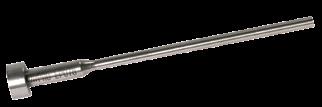
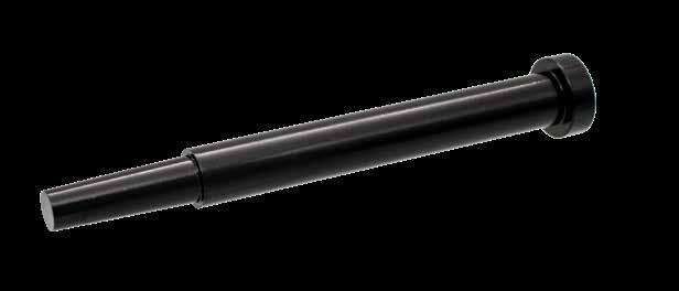
ULTRAPINS ® TREATED STRAIGHT PINS
ALTERNATIVE CONFIGURATIONS AVAILABLE
• To order pins with the keys tangent to the diameter, add “-K” to the end of the catalog number. Ex. EPL250L6-K.
• Mold-Ready UltraPins can be supplied cut-to-length, keyed, and/or engraved at a standard price and delivery. Refer to page A-20 and procomps.com/mold-ready for more information.
• Made-to-order UltraPins can be quoted using the templates at procomps.com.
APPLICATION GUIDELINES
• Maximum operating temperature: 660˚F (350˚C).
• Not recommended for Die Cast or PVC molding. Consider Black Nitrided pins shown on page A-1.
A-8
NOMINAL DIAMETER D ACTUAL PIN DIAMETER H T L=6” D STANDARD L=10” D STANDARD L=14” D STANDARD D ACTUAL OVERSIZED PIN DIAMETER L=10” D .005 OVERSIZE 1/16 .0622 .0619 .25 .125 EPL062L10 5/64 .0778 .0775 .25 .125 EPL078L10 3/32 .0934 .0931 .25 .125 EPL094L10 1/8 .1247 .1244 .25 .125 EPL125L6 EPL125L10 EPL125L14 .1297 .1294 EPL130L10 5/32 .1560 .1557 .28 .156 EPL156L6 EPL156L10 .1610 .1607 EPL161L10 3/16 .1872 .1869 .37 .187 EPL187L6 EPL187L10 EPL187L14 .1922 .1919 EPL192L10 7/32 .2185 .2182 .40 .187 EPL219L6 EPL219L10 .2235 .2232 EPL224L10 1/4 .2497 .2494 .43 .187 EPL250L6 EPL250L10 EPL250L14 .2547 .2544 EPL255L10 5/16 .3122 .3119 .50 .250 EPL312L6 EPL312L10 EPL312L14 3/8 .3747 .3744 .62 .250 EPL375L6 EPL375L10 EPL375L14 7/16 .4372 .4369 .69 .250 EPL437L6 EPL437L10 EPL437L14 1/2 .4997 .4994 .75 .250 EPL500L10 EPL500L14 H +.00 -.01 D T +.000 -.002 -.0003 -.0006 R .03 68 ±2 HRC L+.06 -.00 32 ±2 HRC 49 ±1 HRC R a 4 CAD insertion point M H-13 H Core: 48-50 HRC, Surface: 66-70 HRC M Chrome Plated: .00005-.00007” Thick
ALTERNATIVE CONFIGURATIONS AVAILABLE
ULTRAPINS ® TREATED SHOULDER PINS
• To order pins with the keys tangent to the diameter, add “-K” to the end of the catalog number. Ex. EPL094L6-05-K.
• Mold-Ready UltraPins can be supplied cut-to-length, keyed, and/or engraved at a standard price and delivery. Refer to page A-20 and procomps.com/mold-ready for more information.
• Made-to-order UltraPins can be quoted using the templates at procomps.com.
APPLICATION GUIDELINES
• Maximum operating temperature: 660˚F (350˚C).
• Not recommended for Die Cast or PVC molding. Consider Black Nitrided pins shown on page A-1.
EJECTOR PINS, CORE PINS, SLEEVES A-9
NOMINAL DIAMETER D ACTUAL PIN DIAMETER S SHOULDER LENGTH L=6” D STANDARD L=10” D STANDARD D ACTUAL OVERSIZED PIN DIAMETER L=10” D .005 OVERSIZE 1/32 .0310 .0307 1/2 EPL031L6-05 2 EPL031L6-20 3/64 .0466 .0463 1/2 EPL047L6-05 .0516 .0513 EPL052L10-05 2 EPL047L6-20 EPL047L10-20 EPL052L10-20 3 EPL047L10-30 4 EPL047L10-40 1/16 .0622 .0619 1/2 EPL062L6-05 .0672 .0669 EPL067L10-05 2 EPL062L6-20 EPL062L10-20 EPL067L10-20 3 EPL062L10-30 4 EPL062L10-40 5/64 .0778 .0775 1/2 EPL078L6-05 .0828 .0825 EPL083L10-05 2 EPL078L6-20 EPL078L10-20 EPL083L10-20 3 EPL078L10-30 4 EPL078L10-40 3/32 .0934 .0931 1/2 EPL094L6-05 .0985 .0982 EPL099L10-05 2 EPL094L6-20 EPL094L10-20 EPL099L10-20 3 EPL094L10-30 4 EPL094L10-40 7/64 .1091 .1088 1/2 EPL109L6-05 .1141 .1138 EPL114L10-05 2 EPL109L6-20 EPL109L10-20 EPL114L10-20 .25 +.00 -.01 .125 D -.0003 -.0006 R .03 +.000 -.002 R .25 S L +.06 -.00 .125 +.000 -.001 68 ±2 HRC 32 ±2 HRC 49 ±1 HRC Ra 4 M H-13 H Core: 48-50 HRC, Surface: 66-70 HRC M Chrome Plated: .00005-.00007” Thick CAD insertion point
EJECTOR PINS, CORE PINS, SLEEVES
BLADE EJECTORS INCH STANDARD
• To order Blade Ejectors with the keys tangent to the diameter, add “-K” to the end of the catalog number. Ex. BE500-094L7.5-K.
• Mold-Ready Blades can be supplied cut-to-length, keyed, and/or engraved at a standard price and delivery. Refer to page A-20 and procomps.com/mold-ready for more information.
A-10
X Y D H T L=6.5” L=7.5” L=10.5” .0150 .0460 .062 .250 .125 BE062-015L6.5 BE062-015L7.5 .0150 .1000 .125 .250 .125 BE125-015L6.5 BE125-015L7.5 .0200 .0460 .062 .250 .125 BE062-020L6.5 BE062-020L7.5 .0200 .1000 .125 .250 .125 BE125-020L6.5 BE125-020L7.5 .0240 .1000 .125 .250 .125 BE125-024L6.5 BE125-024L7.5 .0240 .1400 .156 .281 .156 BE156-024L6.5 BE156-024L7.5 .0240 .1720 .187 .375 .187 BE187-024L6.5 BE187-024L7.5 .0320 .1000 .125 .250 .125 BE125-032L6.5 BE125-032L7.5 .0320 .1400 .156 .281 .156 BE156-032L6.5 BE156-032L7.5 .0320 .1720 .187 .375 .187 BE187-032L6.5 BE187-032L7.5 BE187-032L10.5 .0320 .2340 .250 .437 .187 BE250-032L6.5 BE250-032L7.5 BE250-032L10.5 .0320 .2960 .312 .500 .250 BE312-032L7.5 BE312-032L10.5 .0320 .3590 .375 .625 .250 BE375-032L7.5 BE375-032L10.5 .0460 .1000 .125 .250 .125 BE125-046L6.5 BE125-046L7.5 .0460 .1400 .156 .281 .156 BE156-046L6.5 BE156-046L7.5 .0460 .1720 .187 .375 .187 BE187-046L6.5 BE187-046L7.5 BE187-046L10.5 .0460 .2340 .250 .437 .187 BE250-046L6.5 BE250-046L7.5 BE250-046L10.5 .0460 .2960 .312 .500 .250 BE312-046L7.5 BE312-046L10.5 .0460 .3590 .375 .625 .250 BE375-046L7.5 BE375-046L10.5 .0620 .1720 .187 .375 .187 BE187-062L6.5 BE187-062L7.5 BE187-062L10.5 .0620 .2340 .250 .437 .187 BE250-062L6.5 BE250-062L7.5 BE250-062L10.5 .0620 .2960 .312 .500 .250 BE312-062L7.5 BE312-062L10.5 .0620 .3590 .375 .625 .250 BE375-062L7.5 BE375-062L10.5 .0780 .2960 .312 .500 .250 BE312-078L7.5 BE312-078L10.5 .0780 .3590 .375 .625 .250 BE375-078L7.5 BE375-078L10.5 .0780 .4840 .500 .750 .250 BE500-078L7.5 BE500-078L10.5 .0780 .5470 .562 .812 .250 BE562-078L7.5 BE562-078L10.5 .0780 .6090 .625 .875 .250 BE625-078L7.5 BE625-078L10.5 .0940 .4220 .437 .687 .250 BE437-094L7.5 BE437-094L10.5 .0940 .4840 .500 .750 .250 BE500-094L7.5 BE500-094L10.5 .0940 .5470 .562 .812 .250 BE562-094L7.5 BE562-094L10.5 .0940 .6090 .625 .875 .250 BE625-094L7.5 BE625-094L10.5 Blade Length M M=5” M=5” M=6” 59 ±1 HRC 43 ±2 HRC T +.000 -.002 D +.000 -.001 L+.06 -.00 H +.00 -.01 R .03 R 3.5 M +.02 +.06 X +.0000 -.0003 Y +.0000 -.0003 Length Flat Length Flat Thickness Flat Width Blade Ø Head Ø Head Thickness Ra 4 CAD insertion point M O-1 H 58-60 HRC
CONFIGURATIONS AVAILABLE
ALTERNATIVE
ALTERNATIVE CONFIGURATIONS AVAILABLE
BLADE EJECTORS METRIC DIN STANDARD
• To order Blade Ejectors with the keys tangent to the diameter, add “-K” to the end of the catalog number. Ex. BE4-1.2L80-K.
• Mold-Ready Blades can be supplied cut-to-length, keyed, and/or engraved at a standard price and delivery. Refer to page A-20 and procomps.com/mold-ready for more information.
• Made-to-order Blade Ejectors can be quoted using the templates at procomps.com.
EJECTOR PINS, CORE PINS, SLEEVES A-11
X Y D H T R L= 60MM L= 80MM L= 100MM L= 125MM L= 160MM L= 200MM L= 250MM L= 315MM L= 400MM 1.0 3.5 4 8 3 0.3 BE4-1.0L60 BE4-1.0L80 BE4-1.0L100 BE4-1.0L125 BE4-1.0L160 1.2 3.5 4 8 3 0.3 BE4-1.2L80 BE4-1.2L100 BE4-1.2L125 BE4-1.2L160 1.5 4.5 5 10 3 0.3 BE5-1.5L80 BE5-1.5L100 BE5-1.5L125 BE5-1.5L160 1.2 5.5 6 12 5 0.5 BE6-1.2L80 BE6-1.2L100 BE6-1.2L125 BE6-1.2L160 BE6-1.2L200 1.5 5.5 6 12 5 0.5 BE6-1.5L80 BE6-1.5L100 BE6-1.5L125 BE6-1.5L160 BE6-1.5L200 2.0 5.5 6 12 5 0.5 BE6-2.0L80 BE6-2.0L100 BE6-2.0L125 BE6-2.0L160 BE6-2.0L200 1.2 7.5 8 14 5 0.5 BE8-1.2L100 BE8-1.2L125 BE8-1.2L160 BE8-1.2L200 BE8-1.2L250 1.5 7.5 8 14 5 0.5 BE8-1.5L100 BE8-1.5L125 BE8-1.5L160 BE8-1.5L200 BE8-1.5L250 2.0 7.5 8 14 5 0.5 BE8-2.0L100 BE8-2.0L125 BE8-2.0L160 BE8-2.0L200 BE8-2.0L250 BE8-2.0L315 — 1.5 9.5 10 16 5 0.5 BE10-1.5L160 BE10-1.5L200 BE10-1.5L250 BE10-1.5L315 2.0 9.5 10 16 5 0.5 BE10-2.0L160 BE10-2.0L200 BE10-2.0L250 BE10-2.0L315 BE10-2.0L400 2.0 11.5 12 20 7 0.8 BE12-2.0L200 BE12-2.0L250 BE12-2.0L315 BE12-2.0L400 2.5 11.5 12 20 7 0.8 BE12-2.5L200 BE12-2.5L250 BE12-2.5L315 BE12-2.5L400 2.0 15.5 16 22 7 0.8 BE16-2.0L200 BE16-2.0L250 BE16-2.0L315 BE16-2.0L400 2.5 15.5 16 22 7 0.8 BE16-2.5L200 BE16-2.5L250 BE16-2.5L315 BE16-2.5L400 Blade Length M M= 30MM M= 40MM M= 50MM M= 60MM M= 80MM M= 100MM M= 125MM M= 160MM M= 200MM 59 ±1 HRC 43 ±2 HRC T +.00 -.05 D +.00 -.02 L +1.0 -0.0 H +.0 -.2 R R 10 M +1.0 +2.0 X +.000 -.015 Y +.000 -.015 Length Flat Length Flat Thickness Flat Width Blade Ø Head Ø Head Thickness Ra 4 CAD insertion point M 1.2510 (O-1) H 58-60 HRC
EJECTOR PINS, CORE PINS, SLEEVES
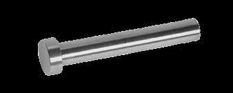
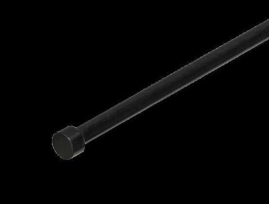
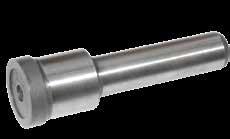
CORE PINS
APPLICATION GUIDELINES
• Core Pin diameter tolerance is +.000/-.001 for a 1" distance from the head.
• Made-to-order
Pins can be quoted using the templates at procomps.com.
A-12
D NOMINAL DIA. H T L=3” L=6” L=10” L=14” 3/32 .25 .125 CPS094L3 CPS094L6 CPS094L10 7/64 .25 .125 CPS109L3 CPS109L6 CPS109L10 1/8 .25 .125 CPS125L3 CPS125L6 CPS125L10 CPS125L14 9/64 .25 .125 CPS141L3 CPS141L6 CPS141L10 CPS141L14 5/32 .28 .156 CPS156L3 CPS156L6 CPS156L10 CPS156L14 11/64 .34 .187 CPS172L3 CPS172L6 CPS172L10 CPS172L14 3/16 .37 .187 CPS187L3 CPS187L6 CPS187L10 CPS187L14 13/64 .37 .187 CPS203L3 CPS203L6 CPS203L10 CPS203L14 7/32 .40 .187 CPS219L3 CPS219L6 CPS219L10 CPS219L14 15/64 .40 .187 CPS234L6 CPS234L10 1/4 .43 .187 CPS250L3 CPS250L6 CPS250L10 CPS250L14 9/32 .43 .250 CPS281L3 CPS281L6 CPS281L10 CPS281L14 5/16 .50 .250 CPS312L3 CPS312L6 CPS312L10 CPS312L14 11/32 .56 .250 CPS344L3 CPS344L6 CPS344L10 CPS344L14 3/8 .62 .250 CPS375L3 CPS375L6 CPS375L10 CPS375L14 13/32 .68 .250 CPS406L3 CPS406L6 CPS406L10 CPS406L14 7/16 .68 .250 CPS437L3 CPS437L6 CPS437L10 CPS437L14 15/32 .75 .250 CPS469L3 CPS469L6 CPS469L10 CPS469L14 1/2 .75 .250 CPS500L3 CPS500L6 CPS500L10 CPS500L14 17/32 .75 .250 CPS531L6 CPS531L10 9/16 .81 .250 CPS562L6 CPS562L10 CPS562L14 5/8 .87 .250 CPS625L6 CPS625L10 CPS625L14 11/16 .93 .250 CPS687L6 CPS687L10 CPS687L14 3/4 1.00 .250 CPS750L6 CPS750L10 CPS750L14 13/16 1.125 .250 CPS812L6 CPS812L10 CPS812L14 7/8 1.125 .250 CPS875L6 CPS875L10 CPS875L14 1 1.25 .250 CPS1000L6 CPS1000L10 CPS1000L14 D NOMINAL DIA. H T L=3” L=6” L=10” L=14” 3/32 .25 .125 CPH094L3 CPH094L6 CPH094L10 7/64 .25 .125 CPH109L3 CPH109L6 CPH109L10 1/8 .25 .125 CPH125L3 CPH125L6 CPH125L10 CPH125L14 9/64 .25 .125 CPH141L3 CPH141L6 CPH141L10 CPH141L14 5/32 .28 .156 CPH156L3 CPH156L6 CPH156L10 CPH156L14 11/64 .34 .187 CPH172L3 CPH172L6 CPH172L10 CPH172L14 3/16 .37 .187 CPH187L3 CPH187L6 CPH187L10 CPH187L14 13/64 .37 .187 CPH203L3 CPH203L6 CPH203L10 CPH203L14 7/32 .40 .187 CPH219L3 CPH219L6 CPH219L10 CPH219L14 15/64 .40 .187 CPH234L6 CPH234L10 1/4 .43 .187 CPH250L3 CPH250L6 CPH250L10 CPH250L14 9/32 .43 .250 CPH281L3 CPH281L6 CPH281L10 CPH281L14 5/16 .50 .250 CPH312L3 CPH312L6 CPH312L10 CPH312L14 11/32 .56 .250 CPH344L3 CPH344L6 CPH344L10 CPH344L14 3/8 .62 .250 CPH375L3 CPH375L6 CPH375L10 CPH375L14 13/32 .68 .250 CPH406L3 CPH406L6 CPH406L10 CPH406L14 7/16 .68 .250 CPH437L3 CPH437L6 CPH437L10 CPH437L14 15/32 .75 .250 CPH469L3 CPH469L6 CPH469L10 CPH469L14 1/2 .75 .250 CPH500L3 CPH500L6 CPH500L10 CPH500L14 17/32 .75 .250 CPH531L6 CPH531L10 9/16 .81 .250 CPH562L6 CPH562L10 CPH562L14 5/8 .87 .250 CPH625L6 CPH625L10 CPH625L14 11/16 .93 .250 CPH687L6 CPH687L10 CPH687L14 3/4 1.00 .250 CPH750L6 CPH750L10 CPH750L14 13/16 1.125 .250 CPH812L6 CPH812L10 CPH812L14 7/8 1.125 .250 CPH875L6 CPH875L10 CPH875L14 1 1.25 .250 CPH1000L6 CPH1000L10 CPH1000L14 H +.00 -.01 D T +.000 -.002 +.0005 +.0010 R .03 L +.3 -.0 Ra 4 CAD insertion point M H-13 H 30-35 HRC M H-13 H 50-55 HRC
ALTERNATIVE CONFIGURATIONS AVAILABLE Core
• Heads are annealed on 6”, 10”, and 14” lengths on the high hardness (CPH) pins.
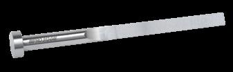
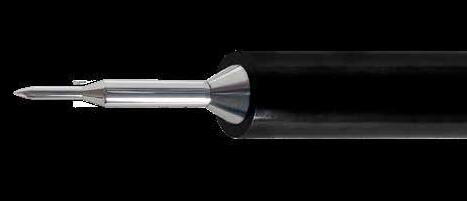
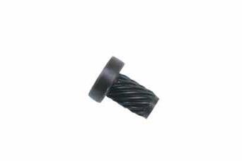
APPLICATION GUIDELINES
• TI Pins allow for the use of wire EDM to the finish diameter, with no step machining required for the core pin.
• Unlike punches, TI Pin heads are precision ground to standard mold tolerances.
ALTERNATIVE CONFIGURATIONS AVAILABLE
• Made-to-order TI Pins can be quoted using the templates at procomps.com.
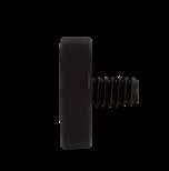
THOUSANDTH INCREMENT PINS
To Order:
Specify the prefix TI- and the three place decimal of the pin required, followed by a “0” if not nominal:
Ex. .090ø = TI-0900 or .252ø = TI-2520
If a nominal size, carry to a four place decimal as listed in the chart at left:
Ex. 5/32ø nominal = TI-1562 or 3/32ø = TI-0937
EJECTOR PINS, CORE PINS, SLEEVES A-13 TI ™ PINS
D DECIMAL PIN DIAMETER H HEAD DIAMETER T HEAD THICKNESS .060 - .062 .093 .125 .0625 .093 .125 .063 - .093 .156 .125 .0937 .156 .125 .094 - .124 .187 .125 .1250 .187 .125 .126 - .156 .218 .125 .1562 .218 .125 .157 - .187 .250 .125 .1875 .250 .125 .188 - .218 .281 .125 .2187 .281 .125 .219 - .249 .312 .125 .2500 .312 .125 .251 - .312 .437 .187 .3125 .437 .187 .313 - .320 .500 .187 D +.03 -.00 +.000 -.002 +.0003 -.0000 2.500 +.00 -.01 H T 62 ±2 HRC R .02 Max Ra 10 CAD insertion point M M2 H 60-64 HRC
EJECTOR PINS, CORE PINS, SLEEVES
EJECTOR SLEEVES
General Dimensions:
N=1-7/8” for ES094 & ES125
N=2-3/8” for ES156 and larger
T=.187” for ES094 thru ES156
T=.250” for ES187 and larger
INCH STANDARD-EXTRA LENGTH SERIES
M H-13 H Core: 40-44 HRC, Surface: 65-75 HRC
General Dimensions:
N=2-3/8” for ES156
N=2-3/4” for ES187 thru ES219
N=3-1/4” for ES250 and larger

T=.187” for ES156
T=.250” for ES187 and larger
ALTERNATIVE CONFIGURATIONS AVAILABLE
• For sleeves that are .005” oversized on the outer diameter (B), add "-OS" to the end of the part number. Ex. ES250L12-OS.
• Sleeves can be ordered with the Black Nitride treatment for better performance. To order, specify "-BN" at the end of the catalog number. Ex. ES437L7-BN.
• To achieve longer lengths, use Sleeve Extensions shown on page A-17.
1/2 .6875 .93 ES500L15 ES500L16 ES500L17 ES500L18
9/16 .7500 1.00 ES562L15 ES562L16 ES562L17 ES562L18
5/8 .8750 1.12 ES625L15 ES625L16 ES625L17 ES625L18 3/4 1.0000 1.25 ES750L15 ES750L16 ES750L17 ES750L18
• Mold-Ready Sleeves can be supplied cut-to-length, keyed, and/or engraved at a standard price and delivery. Refer to page A-20 and procomps.com/mold-ready for more information.
• Made-to-order Sleeves can be quoted using the templates at procomps.com.
A-14
D NOM. I.D. B O.D. H L=3” L=4” L=5” L=6” L=7” L=8” L=9” L=10” L=11” L=12” L=13” L=14” 3/32 .1875 .37 ES094L3 ES094L4 ES094L5 ES094L6 ES094L7 ES094L8 ES094L9 ES094L10 ES094L11 1/8 .2187 .40 ES125L3 ES125L4 ES125L5 ES125L6 ES125L7 ES125L8 ES125L9 ES125L10 ES125L11 5/32 .2500 .43 ES156L4 ES156L5 ES156L6 ES156L7 ES156L8 ES156L9 ES156L10 ES156L11 ES156L12 ES156L13 ES156L14 3/16 .3125 .50 ES187L4 ES187L5 ES187L6 ES187L7 ES187L8 ES187L9 ES187L10 ES187L11 ES187L12 ES187L13 ES187L14 7/32 .3437 .56 ES219L4 ES219L5 ES219L6 ES219L7 ES219L8 ES219L9 ES219L10 ES219L11 ES219L12 ES219L13 ES219L14 1/4 .3750 .62 ES250L4 ES250L5 ES250L6 ES250L7 ES250L8 ES250L9 ES250L10 ES250L11 ES250L12 ES250L13 ES250L14 5/16 .4375 .68 ES312L4 ES312L5 ES312L6 ES312L7 ES312L8 ES312L9 ES312L10 ES312L11 ES312L12 ES312L13 ES312L14 3/8 .5000 .75 ES375L4 ES375L5 ES375L6 ES375L7 ES375L8 ES375L9 ES375L10 ES375L11 ES375L12 ES375L13 ES375L14 7/16 .6250 .87 ES437L4 ES437L5 ES437L6 ES437L7 ES437L8 ES437L9 ES437L10 ES437L11 ES437L12 ES437L13 ES437L14 1/2 .6875 .93 ES500L4 ES500L5 ES500L6 ES500L7 ES500L8 ES500L9 ES500L10 ES500L11 ES500L12 ES500L13 ES500L14 9/16 .7500 1.00 ES562L4 ES562L5 ES562L6 ES562L7 ES562L8 ES562L9 ES562L10 ES562L11 ES562L12 ES562L13 ES562L14 5/8 .8750 1.12 ES625L4 ES625L5 ES625L6 ES625L7 ES625L8 ES625L9 ES625L10 ES625L11 ES625L12 ES625L13 ES625L14 3/4 1.0000 1.25 ES750L4 ES750L5 ES750L6 ES750L7 ES750L8 ES750L9 ES750L10 ES750L11 ES750L12 ES750L13 ES750L14 H +.00 -.01 T +.000 -.002 D +.0003 -.0000 R .03 L +.125 -.000 D+ 1/64 N B -.0004 -.0007 42 ±2 HRC 32 ±2 HRC 70 ±5 HRC (ID & OD) Length OD ID Head Ø Head Thickness Ra 4 CAD insertion point M H-13 H Core: 40-44 HRC, Surface: 65-75 HRC
D NOM. I.D. B O.D. H L=15” L=16” L=17” L=18” 5/32 .2500 .43 ES156L15 ES156L16 ES156L17 ES156L18 3/16 .3125 .50 ES187L15 ES187L16 ES187L17 ES187L18 7/32 .3437 .56 ES219L15 ES219L16 ES219L17 ES219L18 1/4 .3750 .62 ES250L15 ES250L16 ES250L17 ES250L18 5/16 .4375 .68 ES312L15 ES312L16 ES312L17 ES312L18 3/8 .5000 .75 ES375L15 ES375L16 ES375L17 ES375L18 7/16 .6250 .87 ES437L15 ES437L16 ES437L17 ES437L18
General Dimensions:
N=35mm for ESD015 thru ESD025
N=45mm for ESD027 thru ESD10
N=55mm for ESD102 and larger
M H-13 H Core: 40-44 HRC, Surface: 65-75 HRC
EJECTOR PINS, CORE PINS, SLEEVES
EJECTOR SLEEVES METRIC DIN STANDARD
T=3mm for ESD015 thru ESD032
T=5mm for ESD035 thru ESD062
T=7mm for ESD08 thru ESD125
T=9mm for ESD14 and larger
To Order: Specify the ESD prefix with the inner diameter (D), and length. Ex. ESD035L175.
• Sleeves can be ordered with the Black Nitride treatment for better performance. To order, specify "-BN" at the end of the catalog number. Ex. ESD08L250-BN.
ALTERNATIVE CONFIGURATIONS AVAILABLE
• To achieve longer lengths, use Sleeve Extensions on page A-17.
• Mold-Ready Sleeves can be supplied cut-to-length, keyed, and/or engraved at a standard price and delivery. Refer to page A-20 and procomps.com/mold-ready for more information.
• Made-to-order Sleeves can be quoted using the templates at procomps.com.
A-15
CATALOG NUMBER D B H LENGTHS (L) 75MM 100MM 125MM 150MM 175MM 200MM 225MM 250MM 275MM 300MM 325MM 350MM 400MM 450MM ESD015 1.5 3 6 • • • ESD016 1.6 3 6 • • • ESD02 2 4 8 • • • • • ESD022 2.2 4 8 • • • • • ESD025 2.5 5 10 • • • • • • • ESD027 2.7 5 10 • • • • • • • ESD03 3 5 10 • • • • • • • • • • • • • • ESD032 3.2 5 10 • • • • • • • ESD035 3.5 6 12 • • • • • • • ESD037 3.7 6 12 • • • • • • • • • ESD04 4 6 12 • • • • • • • • • • ESD042 4.2 8 14 • • • • • • • ESD05 5 8 14 • • • • • • • • • • • • • • ESD052 5.2 8 14 • • • • • • • • • • • • • • ESD055 5.5 8 14 • • • • • • • • • ESD06 6 10 16 • • • • • • • • • • • • • • ESD062 6.2 10 16 • • • • • • • • • • • • • • ESD08 8 12 20 • • • • • • • • • • • • • • ESD082 8.2 12 20 • • • • • • • • • • • • • • ESD10 10 14 22 • • • • • • • • • • ESD102 10.2 14 22 • • • • • • • • • ESD105 10.5 14 22 • • • • • • ESD12 12 16 22 • • • • • • • • • ESD125 12.5 16 22 • • • • • • • ESD14 14 18 24 • • • • • • • • • • • • • ESD16 16 20 26 • • • • • • • • • • • • • ESD18 18 22 28 • • • • • • • • • • • • • H +.0 –.2 DH5 R 0.8 N B 42 ±2 HRC 67 ±2 HRC (ID & OD) Ra 4 T +.00 –.05 D +.5 g6 L +2.0 –0.0 H +.0 –.2 DH5 R 0.8 N B 42 ±2 HRC 70 ±5 HRC (ID & OD) Ra 4 T +.00 –.05 D +.5 g6 L +2.0 –0.0 CAD insertion point
EJECTOR PINS, CORE PINS, SLEEVES
EJECTOR SLEEVES
THIN WALL SERIES
ALTERNATIVE CONFIGURATIONS AVAILABLE
• To achieve longer lengths, use Sleeve Extensions on page A-17.
• Mold-Ready Sleeves can be supplied cut-to-length, keyed, and/or engraved at a standard price and delivery. Refer to page A-20 and procomps.com/mold-ready for more information.
• Made-to-order Sleeves can be quoted using the templates at procomps.com.
A-16
60° Transition Angle +.05 -.00 L +.000 -.002 +.000 -.001 T +.00 -.01 H D +.0003 -.0000 D -.0003 -.0007 B G S N ±.01 59 ±1 HRC Length OD ID Head Ø Head Thickness Shoulder Ø Shoulder Length +.01 R a 4 CAD insertion point M A-2 H 58-60 HRC M Electroless Nickel PTFE Coated D NOMINAL I.D. D DECIMAL I.D. B O.D. G S H T N L=4” L=6” L=8” L=10” 3/32 .0937 .1563 .188 .500 .37 .187 1.75 ESTW094L4 ESTW094L6 1/8 .1250 .1875 .219 .500 .40 .187 1.75 ESTW125L4 ESTW125L6 ESTW125L8 5/32 .1562 .2187 .250 .500 .43 .187 2.50 ESTW156L4 ESTW156L6 ESTW156L8 ESTW156L10 3/16 .1875 .2500 .312 .625 .50 .250 2.50 ESTW187L4 ESTW187L6 ESTW187L8 ESTW187L10 7/32 .2187 .2813 .344 .625 .56 .250 2.50 ESTW219L4 ESTW219L6 ESTW219L8 ESTW219L10 1/4 .2500 .3125 .375 .625 .62 .250 2.50 ESTW250L4 ESTW250L6 ESTW250L8 ESTW250L10 5/16 .3125 .3750 .438 .625 .68 .250 2.50 ESTW312L4 ESTW312L6 ESTW312L8 ESTW312L10 3/8 .3750 .4375 .500 .625 .75 .250 2.50 ESTW375L4 ESTW375L6 ESTW375L8 ESTW375L10
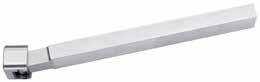
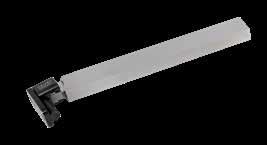
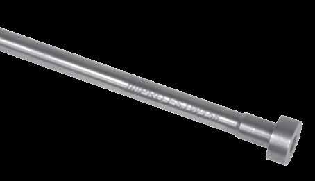
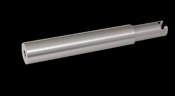
SLEEVE EXTENSIONS: BLANKS
• For extending a Sleeve, begin with a Sleeve Extension Blank and lathe turn the “H” dimension to a standard Ejector Pin head size.
EJECTOR PINS, CORE PINS, SLEEVES A-17
7.0 ±.02 [200mm ±.5] F D J G K H 9.0 ±.02 [238mm ±.5] Metric Standard .250 .50 L ± .02 K +.002 - .000 F +.005 - .000 G +.00 -.01 H +.000 -.002 D +.002 -.000 +.000 -.002 J +.005 -.000 170 B NOMINAL SLEEVE I.D. D O.D. F G H J K L=2” L=3” L=4” 3/32 .625 .193 .385 .875 .188 .18 SXT094L2 SXT094L3 1/8 .625 .224 .416 .875 .188 .18 SXT125L2 SXT125L3 SXT125L4 5/32 .625 .255 .448 .875 .188 .18 SXT156L2 SXT156L3 SXT156L4 3/16 .875 .318 .520 1.125 .251 .21 SXT187L2 SXT187L3 SXT187L4 7/32 .875 .349 .570 1.125 .251 .25 SXT219L2 SXT219L3 SXT219L4 1/4 .875 .380 .630 1.125 .251 .28 SXT250L2 SXT250L3 SXT250L4 5/16 1.000 .443 .698 1.250 .251 .34 SXT312L2 SXT312L3 SXT312L4 3/8 1.000 .505 .760 1.250 .251 .41 SXT375L2 SXT375L3 SXT375L4
CATALOG NUMBER NOMINAL SLEEVE I.D. D O.D. F + .002 - .000 G + .005 - .000 H +.00 - .01 J + .002 - .000 K ± .02 SXT094-B 3/32 .625 .193 .385 .875 .188 .18 SXT125-B 1/8 .625 .224 .416 .875 .188 .18 SXT156-B 5/32 .625 .255 .448 .875 .188 .18 SXT187-B 3/16 .875 .318 .520 1.125 .251 .21 SXT219-B 7/32 .875 .349 .570 1.125 .251 .25 SXT250-B 1/4 .875 .380 .630 1.125 .251 .28 SXT312-B 5/16 1.000 .443 .698 1.250 .251 .34 SXT375-B 3/8 1.000 .505 .760 1.250 .251 .41 M AISI 1215 H 170 Brinell M AISI 1215 H 170 Brinell CAD insertion point Inch Standard CATALOG NUMBER NOMINAL SLEEVE I.D. D O.D. F +.05 - .00 G +.0 1 - .00 H +.0 - .2 J +.05 - .00 K ± .2 SXTD02-B 2 - 2.2 14 4.15 8.3 22 3.03 4 SXTD03-B 2.5 - 3.2 16 5.15 10.3 22 3.03 4 SXTD05-B 3.5 - 5.5 20 8.15 14.3 26 5.03 6 SXTD06-B 6 - 6.2 22 10.15 16.3 28 5.03 7 SXTD08-B 8 - 8.2 25 12.15 20.3 32 7.03 9 SXTD10-B 10 - 12.5 32 16.15 22.3 40 7.03 13
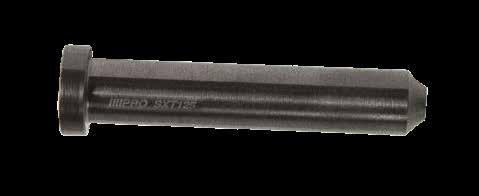
SLEEVE EXTENSIONS
CAD insertion point M AISI 1215 H 170 Brinell S Black Oxide
APPLICATION GUIDELINES
Machining Specifications:
A-18
Ø14 Ø17.5 Ø H T +.001 - .000 +.001 - .000 .125 Ø.76 .03 x 45˚ Ø.453 Clearance for Ejector Pin Tap Drill Size .002 Suggested Clearance H T +.001 - .000 +.001 - .000 .125 Ø1.07 .03 x 45˚ Ø.812 Clearance for Ejector Pin Tap Drill Size .002 Suggested Clearance CPR-50 Inch Standard CATALOG NUMBER A B + .001 - .000 C + .000 - .002 D +.00 - .01 H T CPR-50 .437 .312 .125 .750 .25 1/2-20 CPR-87 .437 .312 .125 1.060 .37 7/8-14 Metric Standard CATALOG NUMBER A B +.02 - .00 C +.00 - .05 D +.0 - .2 H T CPRM-16 11 7 4 20 8 M16-1.5 CPRM-20 11 7 4 26 10 M20-2.5 CPR-50 CORE PIN DIAMETER H 3/32 - 9/64 .563 5/32 .594 11/64 - 1/4 .625 9/32 .688 CPR-87 CORE PIN DIAMETER H 5/16 - 1/2 .688 D T A (Ref) B C H Hex 165 B CAD insertion point M AISI 12L14 H 165 Brinell S Black Oxide M AISI 12L14 H 165 Brinell S Black Oxide CPR-87 14 Ø17.5 Ø H T +.001 - .000 Ø.76 .03 x 45˚ for Size H T +.001 - .000 +.001 - .000 .125 Ø1.07 .03 x 45˚ Ø.812 Clearance for Ejector Pin Tap Drill Size .002 Suggested Clearance CPRM-16 H T +.025 -.000 +.025 -.000 4 Ø20 2 1 x 45˚ Ø14 Clearance for Ejector Pin Tap Drill Size .05 Suggested Clearance +.025 -.000 4 Ø26.2 Ø17.5 (Ø18 for EPD12) Clearance for Ejector Pin Tap/Drill size .05 Suggested Clearance For CPRM-20 H T +.001 - .000 +.001 - .000 .125 Ø.76 .03 x 45˚ Ø.453 Clearance for Ejector Pin Tap Drill Size .002 Suggested Clearance H T +.001 - .000 +.001 - .000 .125 Ø1.07 .03 x 45˚ Ø.812 Clearance for Ejector Pin Tap Drill Size .002 Suggested Clearance CPRM-16 CORE PIN DIAMETER (DIN) H 1.2 - 2.7mm 13.02mm 3 - 5.5mm 14.02mm 6 - 7.5mm 16.02mm CPRM-20 CORE PIN DIAMETER (DIN) H 8 - 11mm 16.02mm 12 - 12.5mm 18.02mm CPRM-20 H T +.025 -.000 +.025 -.000 4 Ø20 2 1 x 45˚ Ø14 Clearance for Ejector Pin Tap Drill Size .05 Suggested Clearance T H +.025 -.000 +.025 -.000 4 Ø26.2 1 x 45˚ Ø17.5 (Ø18 for EPD12) Clearance for Ejector Pin Tap/Drill size .05 Suggested Clearance For CPRM-20 H T +.001 - .000 +.001 - .000 .125 Ø.76 .03 x 45˚ Ø.453 Clearance for Ejector Pin Tap Drill Size .002 Suggested Clearance H T +.001 - .000 +.001 - .000 .125 Ø1.07 .03 x 45˚ Ø.812 Clearance for Ejector Pin Tap Drill Size .002 Suggested Clearance
EJECTOR PINS, CORE PINS, SLEEVES
CORE PIN RETAINERS
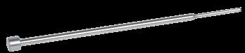
ALTERNATIVE CONFIGURATIONS AVAILABLE
• Made-to-order Return Pins can be quoted using the templates at procomps.com.
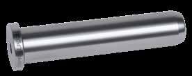
APPLICATION GUIDELINES
• Return Pins are designed to be drilled and tapped on either end.
EJECTOR PINS, CORE PINS, SLEEVES A-19
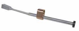
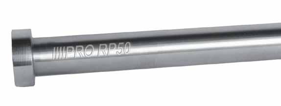
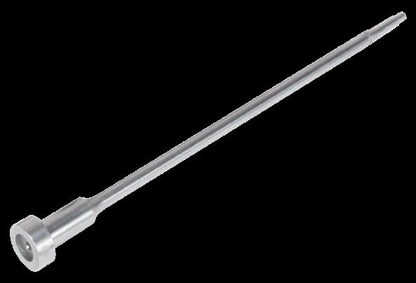
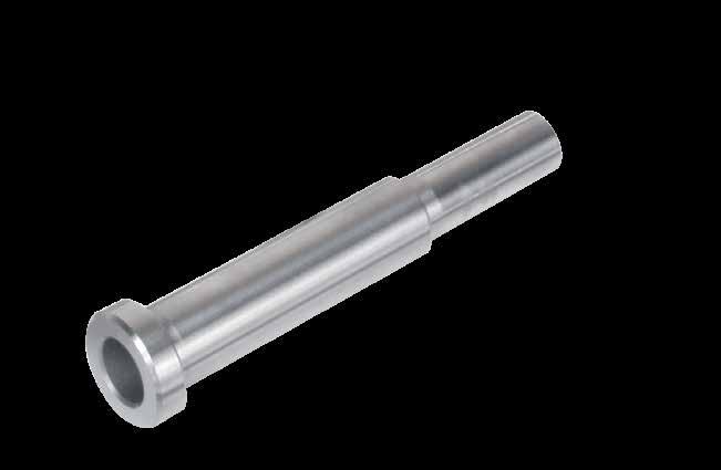
D=1/2 H=3/4 D=5/8 H=7/8 D=3/4 H=1 D=1 H=1-1/4 L CATALOG NUMBER L CATALOG NUMBER L CATALOG NUMBER L CATALOG NUMBER 3-9/16 RP50L3.56 4-1/16 RP62L4.06 4-15/16 RP75L4.93 4-1/16 RP50L4.06 4-9/16 RP62L4.56 5-7/16 RP75L5.43 4-9/16 RP50L4.56 5-1/16 RP62L5.06 5-15/16 RP75L5.93 5-1/16 RP50L5.06 5-9/16 RP62L5.56 6-7/16 RP75L6.43 6 RP100L6 5-9/16 RP50L5.56 6-1/16 RP62L6.06 6-15/16 RP75L6.93 6-1/16 RP50L6.06 6-9/16 RP62L6.56 7-7/16 RP75L7.43 6-9/16 RP50L6.56 7-1/16 RP62L7.06 7-15/16 RP75L7.93 7-9/16 RP62L7.56 8-7/16 RP75L8.43 8-1/16 RP62L8.06 8-15/16 RP75L8.93 9-7/16 RP75L9.43 10 RP100L10 18 RP100L18 H +.00 -.01 +.000 -.002 -.0004 -.0007 .250 L +.015 -.000 R .03 60 ±2 HRC 30 HRC (max) D Ra 4 CAD insertion point M AISI 52100 H Core: 30 HRC Max, Surface: 58-62 HRC
RETURN PINS
EJECTOR PINS, CORE PINS, SLEEVES
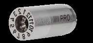
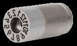
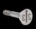
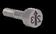
MOLD-READY TM KEYED PINS, SLEEVES, & BLADES
To order Pins, Sleeves, or Blades with the flat machined on the head tangent to the diameter, designate "-K" on the end of the catalog number.
To order Pins, Sleeves, or Blades with the flat machined on the head at a specific distance from the center of the pin, specify the catalog number and the specific distance after the “-K” designation for the flat.
Examples:
• EP437L10-K for a standard Ejector Pin with a key ground tangent.
• EP437L10-K.250 for a standard Ejector Pin with a flat 1/4˝ from center.
• CPH125L6-K.094 for a standard Core Pin with a flat ground 3/32” from center.
• ES562L5-K for a standard Sleeve with a key ground tangent.
• BE125-046L6.5-K.094 for an Ejector Blade with the flat 3/32” from center.
MOLD-READY TM CUT-TO-LENGTH PINS, SLEEVES, & BLADES
To order Pins, Sleeves, or Blades cut to your specified length, +.001/-.000 (+.025/-.000mm), with or without keyed heads, specify the length required after the standard catalog numbers.
Examples:
• EP125L6.752 for a finished length Ejector Pin with a key ground tangent.
• EP437L6.25-K.250 for a finished length Ejector Pin with a flat 1/4˝ from center.
• ES562L5.75 is a for a finished length Ejector Sleeve.
• BE125-046L4.250-K for a finished length Ejector Blade with a key ground tangent.
ADDITIONAL SERVICES PROVIDED
• Detail or model numbers up to 4 digits can be laser engraved on the heads of Pins, Sleeves, and Blades.
• Black Nitride can be applied on Ejector Pins and Sleeves. To order, specify "-BN" at the end of the catalog number. Note: Black Nitride can add up to .0001” on diameters.
• For a quote, send your request to customerservice@procomps.com.
MADE-TO-ORDER CUSTOM PINS & SLEEVES
Progressive can provide custom, finished pins per print, template, or CAD model. For a quote, send your request to tech@procomps.com.
Templates are also available online at procomps.com.
A-20
T +.000 -.002 R .03 L+.06 -.00 R 4 z 68 ±2 32 ±2 HRC 42 ±2 HRC Flat Distance +.000 -.002 +.00mm -.05mm Flat Distance +.002 -.000 +.05mm -.00mm K Tangent +.000 -.002 +.00mm -.05mm L +.001 -.000 +. 025mm -.000mm EP Pin Type Pin Diameter Key 125 L6.752 K.080 - -Length EP Pin Type Pin Diameter Key 125 L6.752 K - -Length
Shoulder
SAB, SHB, SGP
MOLD BASE COMPONENTS SECTION
B
GEB, GGP, GQC
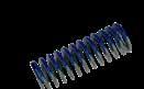
Support Pillars Guided Support Pillars Urethane Springs Springs


SP, SPH
GESP
Leader
Prefix:
Prefix:
Prefix:
Prefix:
Page: B-1 Page: B-2 Page: B-5 Page: B-6
Prefix:
Prefix:
Prefix:
Page:
Page: B-10
Prefix:
Prefix:
Prefix:
Page:
Page:
Page: B-16
Sprue Bushings Locating Rings
Pins: Inch
SPR
LR
PP, PPB
LP
Leader Pins: DIN Guided Ejector Pins Leader Pins: Shoulder
LPD
SLP
LP
B-9
Bushings:
Guided Ejector Bushings Front Load Pins
FLPB
B-12
B-14
Prefix:
Prefix:
Prefix:
Prefix:
Prefix:
Page: B-21 Page: B-23 Page: B-26
PKO
Prefix: SBB Prefix: TD Prefix: SD, STP Prefix: SPC Prefix: PH, PKP Page: B-27 Page: B-28 Page: B-29 Page: B-29 Page: B-30
Stripper Bolts
US
MS, HS
SBLT
Stripper Bolt Bushings Tubular Dowels Stop Discs & Pins Spacers
Extensions
1-25/32 SPRB1-512 SPRB1-534 SPRB1-712 SPRB1-734 SPRB1-912 SPRB1-934 SPRB1-112 SPRB1-134
1-13/32 2-9/32 SPRB2-512 SPRB2-534 SPRB2-712 SPRB2-734 SPRB2-912 SPRB2-934 SPRB2-112 SPRB2-134
1-29/32 2-25/32 SPRB3-512 SPRB3-534 SPRB3-712 SPRB3-734 SPRB3-912 SPRB3-934 SPRB3-112 SPRB3-134
2-13/32 3-9/32 SPRB4-512 SPRB4-534 SPRB4-712 SPRB4-734 SPRB4-912 SPRB4-934 SPRB4-112 SPRB4-134
2-29/32 3-25/32 SPRB5-512 SPRB5-534 SPRB5-712 SPRB5-734 SPRB5-912 SPRB5-934 SPRB5-112 SPRB5-134 SPRB5-N12 SPRB5-N34
3-13/32 4-9/32 SPRB6-512 SPRB6-534 SPRB6-712 SPRB6-734 SPRB6-912 SPRB6-934 SPRB6-112 SPRB6-134
3-29/32 4-25/32 SPRB7-512 SPRB7-534 SPRB7-712 SPRB7-734 SPRB7-912 SPRB7-934 SPRB7-112 SPRB7-134
4-13/32 5-9/32 SPRB8-512 SPRB8-534 SPRB8-712 SPRB8-734 SPRB8-912
For Hot Sprue Bushings, refer to page K-8.
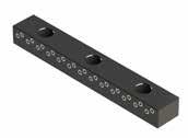
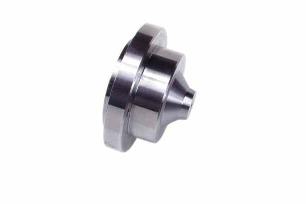
MOLD BASE COMPONENTS B-1 SPRUE
O A L +.01 -.00 2.5˚ Included Angle B Ø2.000 .220 .750 +.000 -.007 +.0007 +.0002 D 44 ±1 HRC ±.005 R B Series D=Ø1.000 B=.875 A L O=5/32 O=7/32 O=9/32 O=11/32 NO HOLE R=1/2 R=3/4 R=1/2 R=3/4 R=1/2 R=3/4 R=1/2 R=3/4 R=1/2 R=3/4
BUSHINGS
29/32
SPRB8-934 SPRB8-112 SPRB8-134 4-29/32 5-25/32 SPRB9-512 SPRB9-534 SPRB9-712 SPRB9-734 SPRB9-912 SPRB9-934 SPRB9-112 SPRB9-134 SPRB9-N12 SPRB9-N34 5-29/32 6-25/32 SPRB10-712 SPRB10-734 SPRB10-912 SPRB10-934 6-29/32 7-25/32 SPRB11-712 SPRB11-734 SPRB11-912 SPRB11-934 SPRB11-112 SPRB11-134 SPRB11-N12 SPRB11-N34 A L O=5/32 O=7/32 O=9/32 O=11/32 NO HOLE R=1/2 R=3/4 R=1/2 R=3/4 R=1/2 R=3/4 R=1/2 R=3/4 R=1/2 R=3/4 1-3/16 1-13/16 SPRA1-512 SPRA1-534 SPRA1-712 SPRA1-734 SPRA1-912 SPRA1-934 SPRA1-112 SPRA1-134 1-11-16 2-5/16 SPRA2-512 SPRA2-534 SPRA2-712 SPRA2-734 SPRA2-912 SPRA2-934 SPRA2-112 SPRA2-134 2-3/16 2-13/16 SPRA3-512 SPRA3-534 SPRA3-712 SPRA3-734 SPRA3-912 SPRA3-934 SPRA3-112 SPRA3-134 SPRA3-N12 SPRA3-N34 2-11/16 3-5/16 SPRA4-512 SPRA4-534 SPRA4-712 SPRA4-734 SPRA4-912 SPRA4-934 SPRA4-112 SPRA4-134 3-3/16 3-13/16 SPRA5-512 SPRA5-534 SPRA5-712 SPRA5-734 SPRA5-912 SPRA5-934 SPRA5-112 SPRA5-134 3-11/16 4-5/16 SPRA6-512 SPRA6-534 SPRA6-712 SPRA6-734 SPRA6-912 SPRA6-934 SPRA6-112 SPRA6-134 4-3/16 4-13/16 SPRA7-512 SPRA7-534 SPRA7-712 SPRA7-734 SPRA7-912 SPRA7-934 SPRA7-112 SPRA7-134 SPRA7-N12 SPRA7-N34 A Series D=Ø1.000 B=.625 A L O=5/32 O=7/32 O=9/32 NO HOLE R=1/2 R=3/4 R=1/2 R=3/4 R=1/2 R=3/4 R=1/2 R=3/4 29/32 1-25/32 SPRU1-512 SPRU1-534 SPRU1-712 SPRU1-734 SPRU1-912 SPRU1-934 1-13/32 2-9/32 SPRU2-512 SPRU2-534 SPRU2-712 SPRU2-734 SPRU2-912 SPRU2-934 1-29/32 2-25/32 SPRU3-512 SPRU3-534 SPRU3-712 SPRU3-734 SPRU3-912 SPRU3-934 SPRU3-N12 SPRU3-N34 2-13/32 3-9/32 SPRU4-512 SPRU4-534 SPRU4-712 SPRU4-734 SPRU4-912 SPRU4-934 2-29/32 3-25/32 SPRU5-512 SPRU5-534 SPRU5-712 SPRU5-734 SPRU5-912 SPRU5-934 SPRU5-N12 SPRU5-N34 U Series D=Ø.750 B=.875
CAD insertion point M AISI 6150 H 43-45 HRC
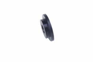
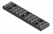
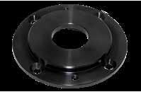
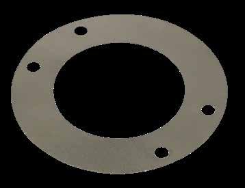
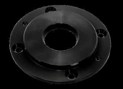
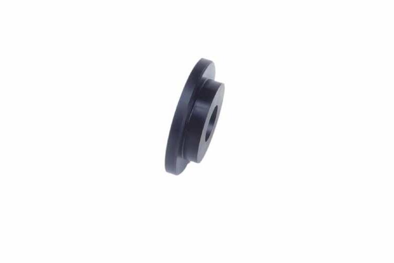
LOCATING RINGS
APPLICATION GUIDELINES
• Enlarged and tapered inner diameters allow for easier material removal.
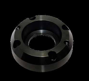
• The four screw holes on each, plus the angled key slots, allow for installation every 45° as shown in the graphic at right.
• Jack out threads help with removal.
• 5/16-18 screws (2) and 3/16 diameter x 2” long dowel pin included.
• Material: 100% recycled reinforced Nylon
• Maximum temperature: 380˚F (190˚C)
• Compatible with LR501.
• 5/16-18 screws (2) included.
MOLD BASE COMPONENTS B-2
STANDARD STYLE LR501 CLAMP STYLE LR504 EXTRA LEAD-IN CLAMP STYLE LR523 EXTRA LEAD-IN LR521 EXTRA LEAD-IN FOR INSULATOR LR541 CLAMP STYLE FOR INSULATOR LR544 LR541 Ø3.995 3 312 B C 218 Ø2 00 Ø3.995 3 312 B C Ø2.375 .531 Ø2 00 1.00 30° 30° 218 .531 1.00 218 Ø2 00 Ø3.995 Ø1.75 Ø2.375 4.625 B C Ø5.500 .531 1.00 218 Ø3.25 Ø3.995 4.625 B C Ø5.500 LR514 LR501 Ø3.995 3 312 B C Ø1 75 Ø2 00 218 .531 LR504 218 Ø2 00 Ø3.995 Ø1.75 4.625 B C Ø5.500 .531 LR519 Ø3.995 3 312 B C 218 Ø2 00 Ø3.995 3 312 B C Ø2.375 .531 Ø2 00 1.00 30° 30° 218 .531 1.00 218 Ø2 00 Ø3.995 Ø1.75 Ø2.375 4.625 B C Ø5.500 .531 1.00 218 Ø3.25 Ø3.995 4.625 B C Ø5.500 LR514 LR501 Ø3.995 3 312 B C Ø1 75 Ø2 00 218 .531 LR504 218 Ø2 00 Ø3.995 Ø1.75 4.625 B C Ø5.500 .531 LR519 Ø3.995 3 312 B C Ø2.375 .531 Ø2 00 1.00 30° 30° 218 Ø3.995 3 312 B C Ø2.250 .781 Ø2 00 1.25 30° 218 1.00 218 Ø2 00 Ø1.75 .531 LR514 LR521 Ø1 75 Ø3.995 3 312 B C .531 Ø2 00 1.00 30° 218 LR523 LR544 Ø1.75 Ø2 00 Ø3.995 3 312 B C Ø2.375 .531 Ø2 00 1.00 30° 30° 218 Ø3.995 3 312 B C Ø2.250 30° Ø3.995 3 312 B C Ø2.375 .781 Ø2 00 1.25 30° .218 1.00 218 Ø2 00 Ø3.995 Ø1.75 Ø2.375 4.625 B C Ø5.500 .531 1.00 218 Ø3.25 Ø3.995 4.625 B C Ø5.500 LR514 LR501 Ø2 00 LR504 LR521 218 Ø2 00 Ø3.995 Ø1.75 4.625 B C Ø5.500 .531 LR519 LR522 Ø1 75 Ø3.995 3 312 B C .531 Ø2 00 1.00 30° 218 LR523 LR541 Ø1.75 30° Ø3.995 Ø1.75 Ø3.000 4.625 B C Ø5.500 Ø3.995 3 312 B C Ø2.375 .781 Ø2 00 1.25 30° .218 1.00 218 Ø3.25 Ø3.995 4.625 B C Ø5.500 LR504 218 Ø2 00 Ø3.995 Ø1.75 4.625 B C Ø5.500 .531 LR519 LR522 LR541 30° 1.25 218 Ø3.995 Ø1.75 Ø3.000 4.625 B C Ø5.500 218 Ø3.990 3.312 B C Ø2.00 74 NYLON LOCATING RING LR501P Ø3.995 3 312 B C Ø2.375 .531 Ø2 00 1.00 30° 218 Ø3.995 3 312 B C Ø2.250 .781 Ø2 00 1.25 30° 218 Ø2 00 LR514 LR521 Ø1 75 Ø3.995 3 312 B C .531 Ø2 00 1.00 30° 218 LR523 LR544 Ø1.75 CAD insertion point M AISI 1018 H 126 Brinell S Black Oxide
APPLICATION GUIDELINES
• Enlarged and tapered inner diameters allow for easier material removal.
• The four screw holes on each, plus the angled key slots, allow for installation every 45° as shown in the graphic on the opposite page.
• Jack out threads help with removal.
• 5/16-18 screws (2) and 3/16 diameter x 2” long dowel pin included.
APPLICATION GUIDELINES
• Shims allow for pre-loading the flanged Locating Rings to compensate for a worn or dished platen as well as compensate for high injection pressures in the center of the mold.
• Three thicknesses are available to enable preload for the center of the mold.
• Sold individually to accommodate stacking requirements.
• Sized with screw clearances to match flanged Locating Rings.
MOLD BASE COMPONENTS B-3
EXTRA LEAD-IN CLAMP STYLE LR514 PLATEN-BACK CLAMP LR519 CLAMP STYLE FOR INSULATOR LR554 EXTENSION NOZZLE STYLE LR522 218 Ø2 00 Ø3.995 3 312 B C Ø2.375 .531 Ø2 00 1.00 30° 30° 218 .531 Ø3.995 3 Ø2 00 1.25 .218 1.00 218 Ø2 00 Ø3.995 Ø1.75 Ø2.375 4.625 B C Ø5.500 .531 1.00 218 Ø3.25 Ø3.995 4.625 B C Ø5.500 LR514 LR501 Ø2 00 218 .531 LR504 LR521 218 Ø2 00 Ø3.995 Ø1.75 4.625 B C Ø5.500 .531 LR519 LR522 Ø1 75 Ø3.995 3 312 B C .531 Ø2 00 1.00 30° 218 LR523 LR541 Ø5.500 218 Ø2 00 Ø3.995 3 312 B C Ø2.375 .531 Ø2 00 1.00 30° 30° 218 .531 Ø3.995 3 312 B C Ø2.375 Ø2 00 1.25 .218 1.00 218 Ø2 00 Ø3.995 Ø1.75 Ø2.375 4.625 B C Ø5.500 .531 1.00 218 Ø3.25 Ø3.995 4.625 B C Ø5.500 LR514 LR501 Ø2 00 218 .531 LR504 LR521 218 Ø2 00 Ø3.995 Ø1.75 4.625 B C Ø5.500 .531 LR519 LR522 Ø1 75 Ø3.995 3 312 B C .531 Ø2 00 1.00 30° 218 LR523 LR541 Ø5.500 Ø3.995 3 312 B C Ø2.375 .531 Ø2 00 1.00 30° 218 Ø3.995 3 312 B C Ø2.250 .781 Ø2 00 1.25 30° 218 Ø3.995 3 312 B C Ø2.375 .781 Ø2 00 1.25 30° .218 1.00 218 Ø3.25 Ø3.995 4.625 B C Ø5.500 LR521 LR522 Ø1 75 Ø3.995 3 312 B C .531 Ø2 00 1.00 30° 218 LR523 LR544 LR541 LR554 Ø1.75 30° 1.25 218 Ø2 00 Ø3.995 Ø1.75 Ø3.000 4.625 B C Ø5.500 .781 Ø3.995 3 312 B C Ø2.375 .781 Ø2 00 1.25 30° .218 1.00 218 Ø3.25 Ø3.995 4.625 B C Ø5.500 Ø2 00 218 .531 LR504 218 Ø2 00 Ø3.995 Ø1.75 4.625 B C Ø5.500 .531 LR519 LR522 LR541 Ø5.500 M AISI 1018 H 170 Brinell S Black Oxide CATALOG NUMBER THICKNESS LRS-02 .002” LRS-03 .003” LRS-05 .005” M 316 Stainless Steel
LOCATING RINGS FLANGE SERIES SHIMS
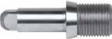
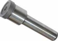
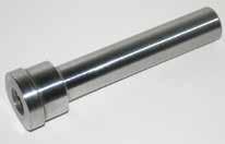
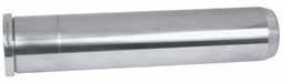
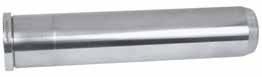
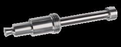
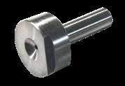
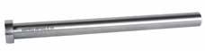
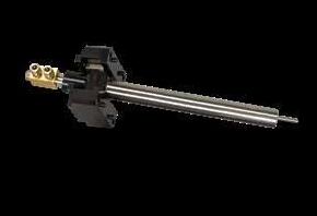
EXTENDED SPRUE BUSHINGS
RUNNER STRIPPER PLATE BUSHING
MOLD BASE COMPONENTS B-4
CATALOG NUMBER A B C D E F G H R SHCS ESB-401 4.490 3.562 2.37 3.12 1.37 1.87 2.256 .375 1/2 #10-32 x 7/8 ESB-402 4.490 3.562 2.37 3.12 1.37 1.81 2.256 .375 3/4 #10-32 x 7/8 ESB-551 5.490 4.625 3.25 3.93 1.87 2.37 2.756 .750 1/2 5/16-18 x 1 ESB-552 5.490 4.625 3.25 3.93 1.87 2.31 2.756 .750 3/4 5/16-18 x 1 3.93 2.37 2.87 3.256 .750 1/2 5/16-18 x 1 3.93 2.37 2.81 3.256 .750 3/4 5/16-18 x 1 B Screw reference for ESB-401 & ESB-402. .885 .380 45˚ 15˚ Ø2.7500 +.0000 - .0004 Ø3.93 3.25 B.C. #10-32 SHCS (2) .25 1.246 +.001 - .000 65 HRC Runner Stripper Plate Bushing 31 45˚ 15˚ D E F G R REF 5/32 +5˚/S 1 246 +.000 - .001 SHCS (2) 3 990 A B C .375 H 30 ±2 HRC CAD insertion point M AISI 4140 Pre-Hard H 28-32 HRC Screws included. Screws included. M AISI 4140 Pre-Hard S Black Nitride H Core: 28-32 HRC, Surface: 65 HRC
Note: Standard “L” provides .010 protrusion per graphic below.
PULLER PINS ™ FOR 3-PLATE RUNNERS
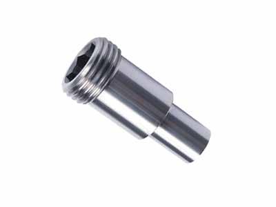
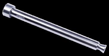
MOLD BASE COMPONENTS B-5
Pin Length Selection Chart G PLATE THICKNESS L FOR 7/8” PLATE L FOR 1-3/8” PLATE 1-3/8 1.813 2.313 1-7/8 2.313 2.813 2-3/8 2.813 3.313 NOMINAL DIAMETER D H T PL L=1.813” L=2.313” L=2.813” L=3.313” OAL CAT. # OAL CAT. # OAL CAT. # OAL CAT. # 5/32 .1562 .28 .156 .125 1.938 PP156L1.9 2.438 PP156L2.4 2.938 PP156L2.9 3.438 PP156L3.4 7/32 .2188 .40 .187 .187 2.000 PP219L2.0 2.500 PP219L2.5 3.000 PP219L3.0 3.500 PP219L3.5 9/32 .2812 .43 .250 .250 2.063 PP281L2.0 2.563 PP281L2.5 3.063 PP281L3.0 3.563 PP281L3.5 5/8-18 Thread Overall Length = Plate -.025 .525ø .3748 L PL OAL T D TR TA H 3/8" Hex .578ø from chart above PL PL R .375ø .010 protrusion .38 Full Thread PD +.000 -.002 -.0004 -.0007 +.00 -.01 ±.003 ± .003 68 ± 2 HRC 52 ±2 HRC +.0000 -.0008 PL X PX P REF 5/8-18 Thread Nominal Pin Dia. +.0005 -.0000 Tap drill for 5/8-18 (Clearance for bushing) R 4 z R .03 .010 10° M H-13 H Core: 40-44 HRC S Ion Nitride 65-70 HRC CAD insertion point Plate (P) Plate (A) Core Pin Retainer CPR-50 .437 P PLATE THICKNESS PX REF X NOMINAL PIN DIAMETER PD T.S.C. R 7/8 1/2 .375 5/32 .145 .020 7/32 .200 .025 9/32 .265 .030 1-3/8 7/8 .500 5/32 .145 .020 7/32 .200 .025 9/32 .265 .030 5/8-18 Thread Overall Length = Plate -.025 .525ø .3748 L PL OAL T D TR TA H 3/8" Hex .578ø from chart above PL PL R .375ø .010 protrusion .38 Full Thread PD +.000 -.002 -.0004 -.0007 +.00 -.01 ±.003 ± .003 68 ± 2 HRC 52 ±2 HRC +.0000 -.0008 PL X PX P REF 5/8-18 Thread Nominal Pin Dia. +.0005 -.0000 Tap drill for 5/8-18 (Clearance for bushing) R 4 z R .03 .010 10°
™ BUSHINGS PULLER PIN DIAMETER P 7/8” PLATE P 1-3/8” PLATE 5/32 PPB156L.87 PPB156L1.37 7/32 PPB219L.87 PPB219L1.37 9/32 PPB281L.87 PPB281L1.37 5/8-18 Thread Overall Length = Plate -.025 .525 .3748 L PL OAL T D H 3/8" Hex +.000 -.002 -.0004 -.0007 +.00 -.01 ±.003 ± .003 68 ± 2 HRC 52 ±2 HRC +.0000 -.0008 R 4 z R .03 .010 M 440C H 50-54 HRC CAD insertion point U.S. Patent No. 8,186,994 Application
PULLER PIN
ALTERNATIVE CONFIGURATIONS AVAILABLE
• For Leader Pins with a 7/8” press fit for guided ejection applications, please refer to page B-8.
• For Metric DIN standard Leader Pins, refer to page B-7.
• For Black Nitride inch standard Leader Pins, refer to page B-10.
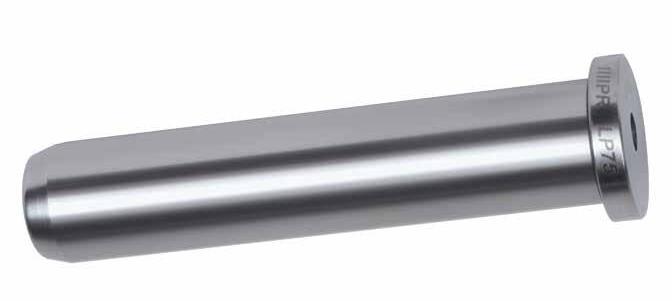
MOLD BASE COMPONENTS B-6 L D=3/4” D=7/8” D=1” D=1-1/4” A CATALOG NUMBER A CATALOG NUMBER A CATALOG NUMBER A CATALOG NUMBER 1-3/4 7/8 LP75L1.75 7/8 LP87L1.75 7/8 LP100L1.75 2-1/4 7/8 LP75L2.25 7/8 LP87L2.25 7/8 LP100L2.25 2-3/4 7/8 LP75L2.75 7/8 LP87L2.75 7/8 LP100L2.75 7/8 LP125L2.75 3-1/4 7/8 LP75L3.25 7/8 LP87L3.25 7/8 LP100L3.25 7/8 LP125L3.25 3-3/4 7/8 LP75L3.75 7/8 LP87L3.75 7/8 LP100L3.75 7/8 LP125L3.75 4-1/4 1-3/8 LP75L4.25 1-3/8 LP87L4.25 1-3/8 LP100L4.25 7/8 LP125L4.25 4-3/4 1-3/8 LP75L4.75 1-3/8 LP87L4.75 1-3/8 LP100L4.75 1-3/8 LP125L4.75 5-1/4 1-3/8 LP75L5.25 1-3/8 LP87L5.25 1-3/8 LP100L5.25 1-3/8 LP125L5.25 5-3/4 1-7/8 LP75L5.75 1-3/8 LP87L5.75 1-3/8 LP100L5.75 1-3/8 LP125L5.75 6-1/4 1-7/8 LP75L6.25 1-3/8 LP87L6.25 1-3/8 LP100L6.25 1-3/8 LP125L6.25 6-3/4 1-7/8 LP75L6.75 1-7/8 LP87L6.75 1-7/8 LP100L6.75 1-7/8 LP125L6.75 7-1/4 1-7/8 LP75L7.25 1-7/8 LP87L7.25 1-7/8 LP100L7.25 1-7/8 LP125L7.25 7-3/4 1-7/8 LP75L7.75 1-7/8 LP87L7.75 1-7/8 LP100L7.75 1-7/8 LP125L7.75 8-1/4 1-7/8 LP87L8.25 1-7/8 LP100L8.25 1-7/8 LP125L8.25 8-3/4 1-7/8 LP87L8.75 1-7/8 LP100L8.75 1-7/8 LP125L8.75 9-1/4 1-7/8 LP75L9.25 1-7/8 LP100L9.25 1-7/8 LP125L9.25 9-3/4 1-7/8 LP100L9.75 1-7/8 LP125L9.75 10-1/4 1-7/8 LP100L10.25 1-7/8 LP125L10.25 10-3/4 1-7/8 LP87L10.75 1-7/8 LP100L10.75 1-7/8 LP125L10.75 11-1/4 1-7/8 LP100L11.25 1-7/8 LP125L11.25 11-3/4 1-7/8 LP100L11.75 1-7/8 LP125L11.75 12-1/4 1-7/8 LP87L12.25 1-7/8 LP100L12.25 1-7/8 LP125L12.25 12-3/4 — 1-7/8 LP125L12.75 13-3/4 — 1-7/8 LP125L13.75 14-3/4 — 1-7/8 LP125L14.75 15-3/4 — 1-7/8 LP125L15.75 L D=1-1/2” D=2” D=2-1/2” D=3” A CATALOG NUMBER A CATALOG NUMBER A CATALOG NUMBER A CATALOG NUMBER 3-3/4 1-3/8 LP150L3.75 4-1/4 1-3/8 LP150L4.25 4-3/4 1-3/8 LP150L4.75 5-1/4 1-3/8 LP150L5.25 5-3/4 1-3/8 LP150L5.75 1-7/8 LP200L5.75 2-3/8 LP250L5.75 6-1/4 1-3/8 LP150L6.25 6-3/4 1-3/8 LP150L6.75 1-7/8 LP200L6.75 2-3/8 LP250L6.75 7-3/4 1-7/8 LP150L7.75 1-7/8 LP200L7.75 2-3/8 LP250L7.75 8-3/4 1-7/8 LP150L8.75 1-7/8 LP200L8.75 2-3/8 LP250L8.75 2-7/8 LP300L8.75 9-3/4 1-7/8 LP150L9.75 1-7/8 LP200L9.75 2-3/8 LP250L9.75 10-3/4 1-7/8 LP150L10.75 1-7/8 LP200L10.75 2-3/8 LP250L10.75 2-7/8 LP300L10.75 11-3/4 1-7/8 LP150L11.75 1-7/8 LP200L11.75 2-3/8 LP250L11.75 12-3/4 1-7/8 LP150L12.75 1-7/8 LP200L12.75 2-3/8 LP250L12.75 2-7/8 LP300L12.75 13-3/4 1-7/8 LP150L13.75 1-7/8 LP200L13.75 2-3/8 LP250L13.75 14-3/4 1-7/8 LP150L14.75 1-7/8 LP200L14.75 2-3/8 LP250L14.75 2-7/8 LP300L14.75 15-3/4 1-7/8 LP150L15.75 1-7/8 LP200L15.75 2-3/8 LP250L15.75 16-3/4 2-3/8 LP200L16.75 2-3/8 LP250L16.75 2-7/8 LP300L16.75 18-3/4 2-3/8 LP200L18.75 2-3/8 LP250L18.75 2-7/8 LP300L18.75 CAD insertion point M AISI 1117 H Surface: 58-62 HRC General Dimensions NOMINAL DIAMETER D +.0000 -.0005 M +.00 -.01 T +.000 -.002 B +.0005 -.0000 K 3/4 .749 .990 .187 .751 3/16 7/8 .874 1.115 .250 .876 3/16 1 .999 1.240 .250 1.001 3/16 1-1/4 1.249 1.490 .312 1.251 1/4 1-1/2 1.499 1.740 .312 1.501 1/4 2 1.999 2.240 .312 2.001 1/2 2-1/2 2.499 2.740 .312 2.501 1/2 3 2.999 3.365 .500 3.001 1/2 T M K B D A L 15˚ Tapered Lead-In +.00 -.03 60 ±2 HRC
ALTERNATIVE CONFIGURATIONS AVAILABLE
• Metric DIN Guided Ejector Bushings are available on page B-14.
• DIN Leader Pins are available with Black Nitride treatment. To order, specify “-BN” at the end of the catalog number. Ex: LPD25L140-BN.
• For inch standard Leader Pins, refer to page B-6 and B-10.
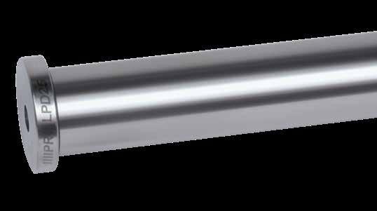
MOLD BASE COMPONENTS B-7
METRIC
General Dimensions D -.007 -.026 B +.011 +.002 M +.0 -.2 T 20 20 24 8 25 25 28 15 30 30 36 15 L D=20MM D=25MM D=30MM A CATALOG NUMBER A CATALOG NUMBER A CATALOG NUMBER 100 28 LPD20L100 35 LPD25L100 45 LPD30L100 120 28 LPD20L120 35 LPD25L120 45 LPD30L120 140 28 LPD20L140 35 LPD25L140 45 LPD30L140 160 45 LPD30L160 CAD insertion point M AISI 1117 (1.7131) H Core: Approx. 25 HRC, Surface: 58-62 HRC T M B D 15˚ Tapered Lead-In A L +.0 -.2 60 ±2 HRC R 8 z
LEADER PINS
DIN STANDARD
GUIDED EJECTOR PINS STRAIGHT STYLE
ALTERNATIVE CONFIGURATIONS AVAILABLE
• Leader Pins with 1-3/8” and other press fit lengths are available on page B-6.
• Guided Ejector Pins are available with Black Nitride treatment. To order, specify “-BN” at the end of the catalog number. Ex: LP100L6.25-P-BN (above) or GEP50X87L425-BN from the chart below.
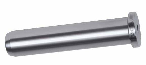
• For Black Nitride inch Standard Leader Pins, refer to page B-10.
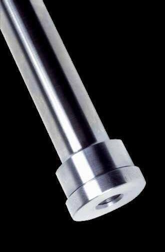
MOLD BASE COMPONENTS B-8
L +.00 -.03 D=1/2” D=3/4” D=7/8” D=1” D=1-1/4” D=1-1/2” D=2” 4-1/4 LP50L4.25-P LP75L4.25-P LP87L4.25-P LP100L4.25-P LP125L4.25 LP150L4.25-P 4-3/4 LP50L4.75-P LP75L4.75-P LP87L4.75-P LP100L4.75-P LP125L4.75-P LP150L4.75-P 5-1/4 LP75L5.25-P LP87L5.25-P LP100L5.25-P LP125L5.25-P LP150L5.25-P 5-3/4 LP75L5.75-P LP87L5.75-P LP100L5.75-P LP125L5.75-P LP150L5.75-P LP200L5.75-P 6-1/4 LP75L6.25-P LP87L6.25-P LP100L6.25-P LP125L6.25-P LP150L6.25-P LP200L6.25-P General Dimensions T M B D 15˚ Tapered Lead-In L 60 ±2 HRC R 8 z .875 M AISI 1117 H Core: Approx. 25 HRC, Surface: 58-62 HRC CAD insertion point NOMINAL DIAMETER D +.0000 -.0005 B +.0005 -.0000 M +.00 -.01 T +.000 -.015 1/2 .499 .751 .853 .187 3/4 .749 1.126 1.250 .312 1 .999 1.376 1.500 .312 A C L D=1/2” D=3/4” D=1” 7/8 2-7/8 3-3/4 GEP50X87L375 3-3/8 4-1/4 GEP50X87L425 GEP75X87L425 GEP100X87L425 3-7/8 4-3/4 GEP50X87L475 GEP75X87L475 GEP100X87L475 4-3/8 5-1/4 GEP50X87L525 GEP75X87L525 GEP100X87L525 4-7/8 5-3/4 GEP75X87L575 GEP100X87L575 1-3/8 3-7/8 5-1/4 GEP100X137L525 4-3/8 5-3/4 GEP100X137L575 4-7/8 6-1/4 GEP100X137L625 General Dimensions D L A C T M 3/32 R +.00 -.03 +.00 -.03 59 ±1 HRC B CAD insertion point M AISI 8620 H Core: Approx.
HRC, Surface: 58-60 HRC
25
NOMINAL DIAMETER D +.0000 -.0005 B +.0005 -.0000 M +.00 -.01 T +.000 -.002 1/2 .499 .501 .740 .187 3/4 .749 .751 .990 .187 7/8 .874 .876 1.115 .250 1 .999 1.001 1.240 .250 1-1/4 1.249 1.251 1.490 .312 1-1/2 1.499 1.501 1.740 .312 2 1.999 2.001 2.240 .312
ALTERNATIVE CONFIGURATIONS AVAILABLE
• Shoulder Leader Pins are available with Black Nitride treatment. To order, specify “-BN” at the end of the catalog number. Ex: SLP75X387L625-BN
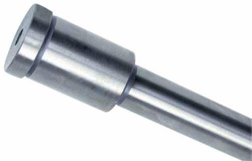
MOLD BASE COMPONENTS B-9 A C L D=1/2” D=3/4” D=1” D=1-1/4” 7/8 7/8 1-3/4 SLP50X87L175 SLP75X87L175 1-3/8 2-1/4 SLP50X87L225 SLP75X87L225 1-7/8 2-3/4 SLP50X87L275 2-3/8 3-1/4 SLP50X87L325 SLP75X87L325 2-7/8 3-3/4 SLP75X87L375 SLP100X87L375 1-3/8 7/8 2-1/4 SLP50X137L225 SLP75X137L225 1-3/8 2-3/4 SLP50X137L275 SLP75X137L275 SLP100X137L275 1-7/8 3-1/4 SLP50X137L325 SLP75X137L325 SLP100X137L325 2-3/8 3-3/4 SLP75X137L375 2-7/8 4-1/4 SLP75X137L425 SLP100X137L425 3-3/8 4-3/4 SLP75X137L475 SLP125X137L475 1-7/8 7/8 2-3/4 SLP50X187L275 1-3/8 3-1/4 SLP50X187L325 SLP75X187L325 1-7/8 3-3/4 SLP50X187L375 SLP75X187L375 SLP100X187L375 2-3/8 4-1/4 SLP75X187L425 SLP100X187L425 SLP125X187L425 2-7/8 4-3/4 SLP75X187L475 SLP100X187L475 3-3/8 5-1/4 SLP75X187L525 3-7/8 5-3/4 SLP75X187L575 SLP125X187L575 2-3/8 7/8 3-1/4 SLP50X237L325 1-3/8 3-3/4 SLP75X237L375 1-7/8 4-1/4 SLP75X237L425 SLP100X237L425 2-3/8 4-3/4 SLP75X237L475 SLP100X237L475 2-7/8 5-1/4 SLP75X237L525 SLP125X237L525 3-3/8 5-3/4 — SLP100X237L575 3-7/8 6-1/4 SLP125X237L625 2-7/8 1-3/8 4-1/4 SLP75X287L425 1-7/8 4-3/4 SLP75X287L475 SLP100X287L475 2-3/8 5-1/4 SLP75X287L525 SLP100X287L525 2-7/8 5-3/4 SLP75X287L575 SLP100X287L575 SLP125X287L575 3-3/8 6-1/4 SLP100X287L625 3-7/8 6-3/4 SLP75X287L675 4-3/8 7-1/4 SLP125X287L725 3-3/8 2-3/8 5-3/4 SLP75X337L575 3-3/8 6-3/4 SLP75X337L675 4-3/8 7-3/4 — SLP100X337L775 3-7/8 2-3/8 6-1/4 SLP75X387L625 SLP100X387L625 2-7/8 6-3/4 SLP75X387L675 SLP100X387L675 4-3/8 2-7/8 7-1/4 SLP100X437L725 3-3/8 7-3/4 SLP125X437L775 4-7/8 3-7/8 8-3/4 SLP100X487L875 SLP125X487L875 5-7/8 3-7/8 9-3/4 SLP100X587L975 5-7/8 11-3/4 SLP125X587L1175 CAD insertion point M AISI 1117 H Surface: 58-62 HRC K T M B D A L C .09 R +.00 - .03 +.00 - .03 60 ± 2 HRC General Dimensions NOM. DIA. D +.0000 -.0005 B +.0005 -.0000 M +.000 -.010 T +.000 -.002 K 1/2 .499 .751 .853 .187 3/16 3/4 .749 1.126 1.250 .312 3/16 1 .999 1.376 1.500 .312 3/16 1-1/4 1.249 1.626 1.750 .312 1/4
M AISI 1117 H
Surface: 66-70 HRC S Black Nitride
ALTERNATIVE CONFIGURATIONS AVAILABLE
• Any standard Leader Pin can be treated with Black Nitride. Add “-BN” to the catalog number and contact Customer Service for a quotation.
• For Leader Pins with a 7/8” press fit for guided ejection applications, please refer to page B-8.
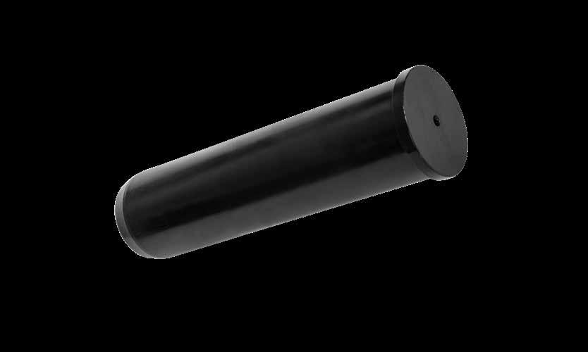
B-10 L D=1” D=1-1/4” D=1-1/2” D=2” D=2-1/2” D=3” A CATALOG NUMBER A CATALOG NUMBER A CATALOG NUMBER A CATALOG NUMBER A CATALOG NUMBER A CATALOG NUMBER 7-1/4 1-7/8 LP100L7.25-BN 7-3/4 1-7/8 LP100L7.75-BN 1-7/8 LP125L7.75-BN 1-7/8 LP150L7.75-BN 1-7/8 LP200L7.75-BN — 8-1/4 — 1-7/8 LP125L8.25-BN 8-3/4 — — 1-7/8 LP150L8.75-BN 1-7/8 LP200L8.75-BN 2-3/8 LP250L8.75-BN 2-7/8 LP300L8.75-BN 9-3/4 — — — 1-7/8 LP200L9.75-BN 2-3/8 LP250L9.75-BN 10-3/4 — 1-7/8 LP125L10.75-BN 1-7/8 LP150L10.75-BN 1-7/8 LP200L10.75-BN 2-3/8 LP250L10.75-BN 2-7/8 LP300L10.75-BN 12-3/4 — — — — — 2-7/8 LP300L12.75-BN 15-3/4 — — — 1-7/8 LP200L15.75-BN 2-3/8 LP250L15.75-BN — 18-3/4 — — 2-3/8 LP200L18.75-BN 2-3/8 LP250L18.75-BN 2-7/8 LP300L18.75-BN CAD insertion point T M K B D A L 15˚ Tapered Lead-In +.00 -.03 68 ±2 HRC General Dimensions NOMINAL DIAMETER D ±.0005 M +.00 -.01 T +.000 -.002 B +.0005 -.0000 K 1 .999 1.240 .250 1.001 3/16 1-1/4 1.249 1.490 .312 1.251 1/4 1-1/2 1.499 1.740 .312 1.501 1/4 2 1.999 2.240 .312 2.001 1/2 2-1/2 2.499 2.740 .312 2.501 1/2 3 2.999 3.365 .500 3.001 1/2
INCH STANDARD SHOULDER STYLE-BLACK NITRIDE
INCH STANDARD GUIDED EJECTOR-BLACK NITRIDE
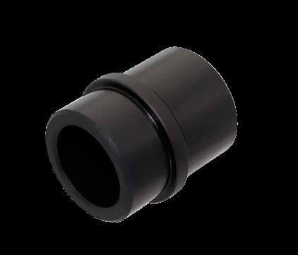
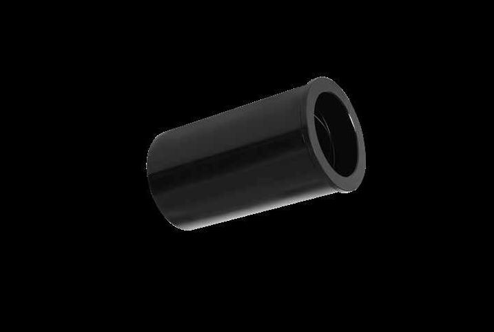
B-11
L D=1” D=1-1/4” D=1-1/2” D=2” D=2-1/2” D=3” 4-7/8 STL100L4.87-BN STL125L4.87-BN STL150L4.87-BN STL200L4.87-BN STL250L4.87-BN STL300L4.87-BN 5-7/8 STL100L5.87-BN STL125L5.87-BN STL150L5.87-BN STL200L5.87-BN STL250L5.87-BN STL300L5.87-BN 7-7/8 STL300L7.87-BN B D M 2 x D L T 68 ±2 +.000 -.030 NOMINAL DIAMETER D +.0005 -.0000 B +.0005 -.0000 M +.00 -.01 T +.00 -.01 1 1.0005 1.3755 1.552 .187 1-1/4 1.2505 1.6255 1.802 .187 1-1/2 1.5005 2.0005 2.177 .187 2 2.0005 2.5005 2.677 .187 2-1/2 2.5005 3.2505 3.427 .187 3 3.0005 3.7505 3.990 .500 General Dimensions M AISI 1117 H Surface: 66-70 HRC S Black Nitride CATALOG NUMBER NOMINAL DIAMETER D +.0005 -.0000 H +.0005 -.0000 C +.000 -.001 M +.00 -.01 B L +.00 -.03 GEB50-BN 1/2 .5005 .7505 .7490 .853 1.00 1.50 GEB75-BN 3/4 .7505 1.1255 1.1240 1.302 1.00 1.50 GEB87-BN 7/8 .8755 1.2505 1.2490 1.427 1.00 1.50 GEB100-BN 1 1.0005 1.3755 1.3740 1.552 1.12 1.75 GEB125-BN 1-1/4 1.2505 1.6255 1.6240 1.802 1.12 1.75 GEB150-BN 1-1/2 1.5005 2.0005 1.9990 2.177 1.12 1.75 GEB200-BN 2 2.0005 2.5005 2.4990 2.687 1.62 2.25 M AISI 1117 H Surface: 66-70 HRC S Black Nitride CD L HM B .187 68 ±2 CAD insertion point
Note: To order replacement lubricating strips, specify the prefix “BSHSTRP” with the inner diameter. Ex: BSHSTRP-125.
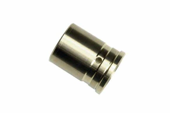
MOLD BASE COMPONENTS B-12
L D=1/2” D=3/4” D=7/8” D=1” D=1-1/4” D=1-1/2” D=2” D=2-1/2” D=3” 7/8 SAB50L.87 SAB75L.87 SAB87L.87 SAB100L.87 SAB125L.87 SAB150L.87 — 1-3/8 SAB50L1.37 SAB75L1.37 SAB87L1.37 SAB100L1.37 SAB125L1.37 SAB150L1.37 SAB200L1.37 SAB250L1.37 1-7/8 SAB50L1.87 SAB75L1.87 SAB87L1.87 SAB100L1.87 SAB125L1.87 SAB150L1.87 SAB200L1.87 SAB250L1.87 2-3/8 SAB50L2.37 SAB75L2.37 SAB87L2.37 SAB100L2.37 SAB125L2.37 SAB150L2.37 SAB200L2.37 SAB250L2.37 2-7/8 SAB75L2.87 SAB87L2.87 SAB100L2.87 SAB125L2.87 SAB150L2.87 SAB200L2.87 SAB250L2.87 3-3/8 SAB75L3.37 SAB87L3.37 SAB100L3.37 SAB125L3.37 SAB150L3.37 SAB200L3.37 SAB250L3.37 3-7/8 SAB75L3.87 SAB87L3.87 SAB100L3.87 SAB125L3.87 SAB150L3.87 SAB200L3.87 SAB250L3.87 SAB300L3.87 4-3/8 SAB75L4.37 SAB87L4.37 SAB100L4.37 SAB125L4.37 SAB150L4.37 SAB200L4.37 SAB250L4.37 4-7/8 SAB75L4.87 SAB87L4.87 SAB100L4.87 SAB125L4.87 SAB150L4.87 SAB200L4.87 SAB250L4.87 SAB300L4.87 5-7/8 SAB75L5.87 SAB87L5.87 SAB100L5.87 SAB125L5.87 SAB150L5.87 SAB200L5.87 SAB250L5.87 SAB300L5.87 7-7/8 SAB300L7.87 B D M X L T Y Lubricating Strip (included) Ø.187 Grease Hole (Ø.125 on all 7/8" lengths) 170 B +.000 -.060 NOMINAL DIAMETER D +.0005 -.0000 B +.0005 -.0000 M +.00 -.01 T +.00 -.01 1/2 .5005 .7505 .853 .187 3/4 .7505 1.1255 1.302 .187 7/8 .8755 1.2505 1.427 .187 1 1.0005 1.3755 1.552 .187 1-1/4 1.2505 1.6255 1.802 .187 1-1/2 1.5005 2.0005 2.177 .187 2 2.0005 2.5005 2.677 .187 2-1/2 2.5005 3.2505 3.427 .187 3 3.0005 3.7505 3.990 .500 General Dimensions Grease Hole and Clearance Dimensions L D=1/2- 7/8” D=1” D=1-1/4” D=1-1/2” D=2” D=2-1/2- 3” X Y X Y X Y X Y X Y X Y 7/8 .43 .43 .43 .43 1-3/8 .62 .62 .62 .62 .62 .62 1-7/8 .62 .62 .62 .62 .62 .62 2-3/8 .50 .81 .81 .81 .81 .81 .81 2-7/8 .50 .81 .50 .81 .81 .81 .81 .81 3-3/8 1.00 .81 .50 .81 .50 .81 .81 .81 .81 3-7/8 1.00 .81 .50 .81 .50 .81 .50 .81 .81 .81 4-3/8 1.50 .81 1.00 .81 1.00 .81 .50 .81 .81 .81 4-7/8 1.50 .81 1.00 .81 1.00 .81 1.00 .81 .50 1.31 1.31 5-7/8 2.00 .81 1.50 .81 1.50 .81 1.50 .81 1.00 1.31 .50 1.31 7-7/8 .50 1.31 CAD insertion point M CA954 Solid Bronze H 170 Brinell
BUSHINGS SHOULDER STYLE-SOLID BRONZE
BRONZE PLATED SHOULDER BUSHINGS
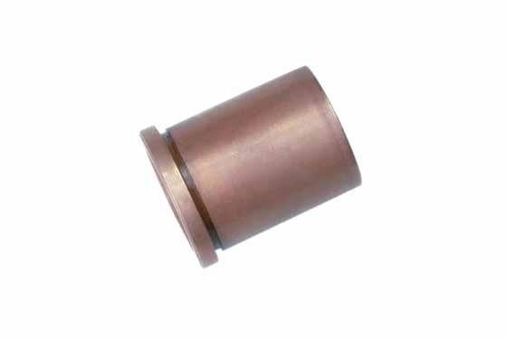
M AISI 1026 H 22-28 HRC S Bronze Plated: .004” Deep
• Bronze plated shoulder bushings have internal grease grooves. Grease entry hole to be machined by mold maker.
• The bearing of the inner diameter is through, where the clearance “X” on page B-12 does not apply.
• Not available in 1/2” diameter.
To Order: Specify “SHB” in the prefix to replace “SAB” in the chart on the previous page. Example: SHB200L2.37 for 2” ID x 2.37 long bushings.
GRAPHITE PLUGGED SHOULDER BUSHINGS
M CA954 with oil impregnated graphite plugs H 170 Brinell
• Graphite plugs are not compatible with grease. Use a light 20 weight oil at startup to begin lubrication.
• The bearing of the inner diameter is through, where the clearance “X” on page B-12 does not apply.
• Not available in 1/2” diameter.
To Order: Specify “SGP” in the prefix to replace “SAB” in the chart on the previous page.
Example: SGP200L2.37 for 2” ID x 2.37 long bushings.
STEEL SHOULDER BUSHINGS
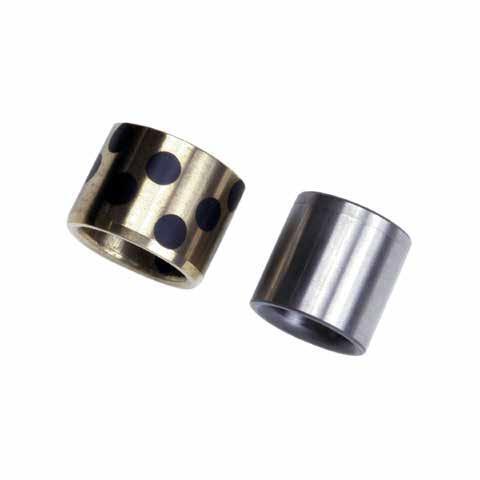

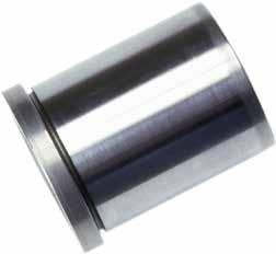
M AISI 1117 H 58-62 HRC
• Steel (hardened) shoulder bushings have internal grease grooves. Grease entry hole to be machined by mold maker.
• The bearing of the inner diameter is 2 x the ID, where the clearance “X” on page B-12 does not apply.
• Steel Bushings are available with Black Nitride treatment. Refer to page B-11.
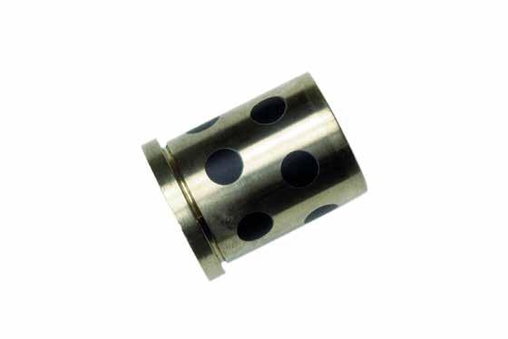
To Order: Specify “STL” in the prefix to replace “SAB” in the chart on the previous page. Example: STL200L2.37 for 2” ID x 2.37 long bushings.
M Non-Plated Steel: AISI 1117 H 58-62 HRC
M Graphite Plugged: CA954 H 170 Brinell
CAD insertion point
Using grease will inhibit the function of the graphite plugs. Instead, use a light 20 weight oil at startup to begin lubrication.
MOLD BASE COMPONENTS B-13
SHOULDER STYLE
BUSHINGS
NOMINAL DIAMETER D +.0005 -.0000 M +.0005 -.0000 L +.00 -.03 CATALOG NUMBER STANDARD STEEL CATALOG NUMBER GRAPHITE PLUGGED 1/2 .5005 .7505 7/8 1-3/8 STB50L.87 STB50L1.37 3/4 .7505 1.1255 7/8 1-3/8 STB75L.87 STB75L1.37 STGP75L.87 STGP75L1.37 7/8 .8755 1.2505 1-3/8 1-1/2 STB87L1.37 STGP87L1.50 1 1.0005 1.3755 1-3/8 STB100L1.37 STGP100L1.37 1-1/4 1.2505 1.6255 1-3/8 1-7/8 STB125L1.37 STB125L1.87 STGP125L1.37 STGP125L1.87 1-1/2 1.5005 2.0005 1-3/8 1-7/8 STB150L1.37 STB150L1.87 STGP150L1.37 STGP150L1.87 2 2.0005 2.5005 3-7/8 STB200L3.87 STGP200L3.87 2-1/2 2.5005 3.2505 4-7/8 STB250L4.87 STGP250L4.87 D +.0005 -.0000 M +.0005 -.0000 L +.00 -.03
GUIDED EJECTOR BUSHINGS
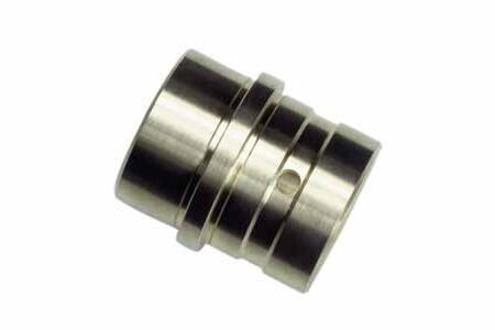
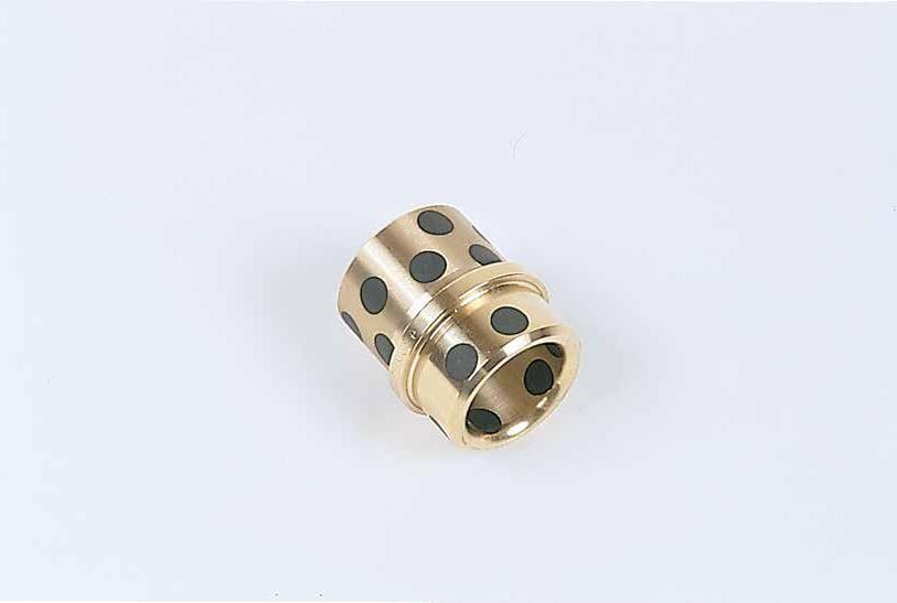
SOLID BRONZE
Using grease will inhibit the function of the graphite plugs. Instead, use a light 20 weight oil at startup to begin lubrication.
MOLD BASE COMPONENTS B-14
CATALOG NUMBER NOMINAL DIAMETER D +.0005 -.0000 H +.0005 -.0000 C +.000 -.001 M +.00 -.01 B K L +.00 -.03 GEB50 1/2 .5005 .7505 .7490 .853 1.00 .56 1.50 GEB75 3/4 .7505 1.1255 1.1240 1.302 1.00 .56 1.50 GEB87 7/8 .8755 1.2505 1.2490 1.427 1.00 .56 1.50 GEB100 1 1.0005 1.3755 1.3740 1.552 1.12 .62 1.75 GEB125 1-1/4 1.2505 1.6255 1.6240 1.802 1.12 .62 1.75 GEB150 1-1/2 1.5005 2.0005 1.9990 2.177 1.12 .62 1.75 GEB200 2 2.0005 2.5005 2.4990 2.687 1.62 .80 2.25 CD L K HM B .187 (5mm) 170 B Inch Standard CATALOG NUMBER D +.013 +.026 H +.01 -.00 C -.01 -.03 M +.00 -.13 B K L +.0 -.8 GEBD20 20 26 26 28 25 15 37 GEBD25 25 32 32 35 29 16 45 GEBD30 30 38 38 41 29 16 45 Metric Standard CAD insertion point M
CA954 Solid Bronze H 170 Brinell
CATALOG NUMBER NOMINAL DIAMETER D +.0005 -.0000 H +.0005 -.0000 C +.000 -.001 M +.00 -.01 B L +.00 -.03 GGP75 3/4 .751 1.1255 1.1240 1.302 1.00 1.50 GGP87 7/8 .876 1.2505 1.2490 1.427 1.00 1.50 GGP100 1 1.001 1.3755 1.3740 1.552 1.12 1.75 GGP125 1-1/4 1.251 1.6255 1.6240 1.802 1.12 1.75 GGP150 1-1/2 1.501 2.0005 1.9990 2.177 1.12 1.75 GGP200 2 2.001 2.5005 2.4990 2.687 1.62 2.25 Metric
M CA954 with oil impregnated graphite plugs H 170 Brinell
DIN Leader Pins are sold on page B-7.
GUIDED EJECTOR BUSHINGS
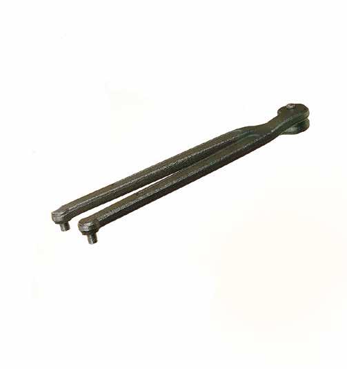
APPLICATION GUIDELINES
• QC Bushings are sold in assembly.
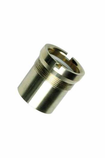
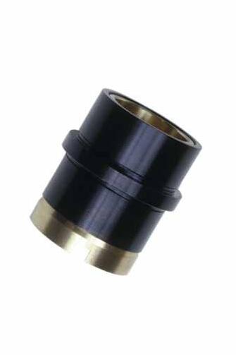
• Replacement liners are sold below. For additional sizes, contact Customer Service.
• To order replacement lubricating strips, specify the prefix “BSHSTRP” with the inner diameter. Ex: BSHSTRP-125.
REPLACEMENT LINERS
APPLICATION GUIDELINES
• To order replacement lubricating strips, specify the prefix “BSHSTRP” with the inner diameter. Ex: BSHSTRP-125.
• Note: References to “SQC” Shoulder Bushings are for legacy tools. For tools requiring Shoulder Bushings, please refer to pages B-11 through B-13.
MOLD BASE COMPONENTS B-15
CATALOG NUMBER NOMINAL DIAMETER D +.0005 -.0000 H +.0005 -.0000 C +.000 -.001 M +.00 -.01 B L +.000 -.015 GQC50 1/2 .5005 .7505 .7490 .853 1.00 1.50 GQC75 3/4 .7505 1.1255 1.1240 1.302 1.00 1.50 GQC87 7/8 .8755 1.2505 1.2490 1.427 1.00 1.50 GQC100 1 1.0005 1.3755 1.3740 1.552 1.12 1.75 GQC125 1-1/4 1.2505 1.6255 1.6240 1.802 1.12 1.75 GQC150 1-1/2 1.5005 2.0005 1.9990 2.177 1.12 1.75 170 B C D L H M B .187 Liner: M CA954 Solid Bronze H 170 Brinell Body: M AISI 12L14 H 170 Brinell S Black Oxide CATALOG NUMBER DESCRIPTION SW-100 Adjustable Spanner Wrench M CA954 Solid Bronze H 170 Brinell M Hardened Steel CAD insertion point
SPANNER WRENCH INNER DIAMETER LINER CATALOG NUMBER FITS BUSHINGS 1/2 BL50L1.50 GQC50 3/4 BL75L.87 SQC75L.87 BL75L1.37 GQC75 SQC75L1.37 SQC75L1.87 SQC75L2.37 SQC75L2.87 7/8 BL87L.87 SQC87L.87 BL87L1.37 GQC87 SQC87L1.37 SQC87L1.87 SQC87L2.37 SQC87L2.87 INNER DIAMETER LINER CATALOG NUMBER FITS BUSHINGS 1 BL100L1.37 SQC100L1.37 BL100L1.75 GQC100 SQC100L1.87 SQC100L2.37 SQC100L2.87 SQC100L3.37 1-1/4 BL125L1.37 SQC125L1.37 BL125L1.75 GQC125 SQC125L1.87 BL125L2.37 SQC125L2.37 SQC125L2.87 SQC125L3.37 SQC125L3.87 1-1/2 BL150L1.75 GQC150 SQC150L1.87
FRONT LOADING PINS AND BUSHINGS
Sold in
of (1) pin and (1) bushing.
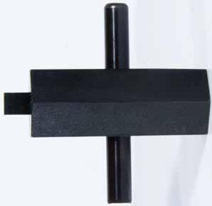
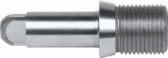
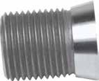
INSTALLATION WRENCH
WR-312 For 5/16” ID Bushing
WR-437 For 7/16” ID Bushing WR-500 For 1/2” ID Bushing WR-750 For 3/4” ID
MOLD
COMPONENTS B-16
BASE
CATALOG NUMBER DESCRIPTION
L M M A A D THD THD E H H +.000 -.002 +.000 -.002 +.000 -.001 +.001 -.000 ±.005 ±.005 R .03 15˚ 15˚ CATALOG NUMBER NOMINAL DIAMETER D E THD UNF H L M A FLPB31L.62 5/16 .3125 .3130 1/2-20 .609 .62 .670 .20 FLPB43L.57 7/16 .4375 .4380 5/8-18 .747 .57 .850 .25 FLPB43L.75 7/16 .4375 .4380 5/8-18 .747 .75 .850 .25 FLPB50L.58 1/2 .5000 .5005 11/16-16 .807 .58 .845 .25 FLPB75L.70 3/4 .7500 .7505 1-12 1.115 .70 1.255 .25 FLPB75L1.10 3/4 .7500 .7505 1-12 1.115 1.10 1.255 .25 FLPB75L1.75 3/4 .7500 .7505 1-12 1.115 1.75 1.255 .25 FLPB100L1.10 1 1.0000 1.0005 1 1/4-16 1.370 1.10 1.224 .25
Bushing WR-100 For 1” ID Bushing
M H-13 H Core: 40-45 HRC, Surface: 65-70 HRC S Nitride CAD insertion point
sets
M CRS H Case Hardened S Black Oxide
GUIDE BLOCKS
FRONT LOADING PINS & BUSHINGS SERIES
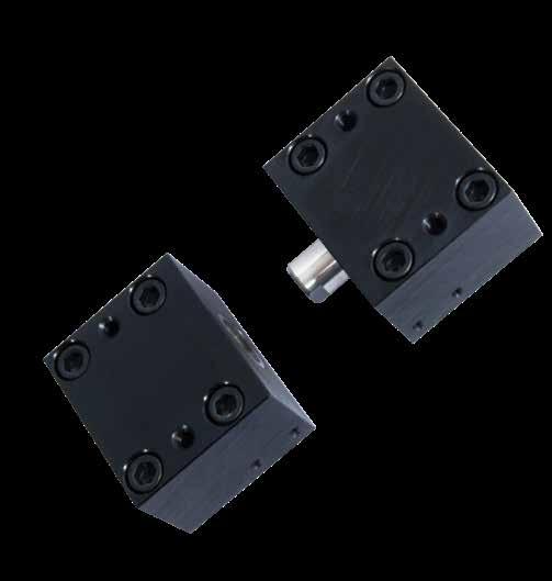
MOLD BASE COMPONENTS B-17
.625 .250 THD 3/8-16 SHCS (4) #10-32 threads to accept the CounterView Attachment sold on page F-10 5/6-18 thread for removal Ø3/8 Dowel Pins for alignment 15˚ D D 1.000 1.375 3.000 2.500 .375 .750 2.125 1.750 .875 1.125 1.500 PL CATALOG NUMBER D PIN/BUSHING DIAMETER THD UNF GBK-75 3/4 1-12 GBK-100 1 1 1/4-16
Sold in sets of (2) identical blocks. Pins and bushings sold separately on page B-16.
M
A-36 H Pre-Hard S Black Oxide
CAD insertion point
Threaded Support Pillars
Socket Head Cap Screws are included with all Support Pillars. 1” long screws are used with the Threaded Pillars. Refer to the chart for the Counterbored Pillar screw size.
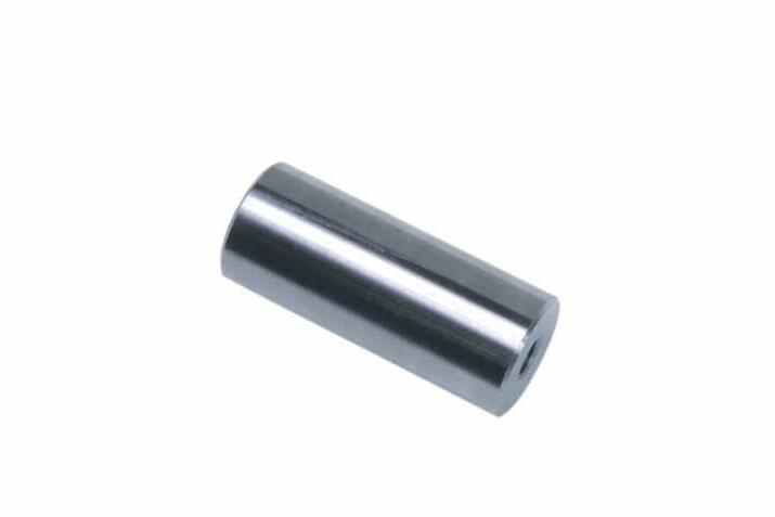
All 2.5”, 4.5” and 8” long Threaded Support Pillars are tapped for a set screw enabling a second pillar to be attached as an extension.
All 2.5”, 4.5” and 8” long Threaded Support Pillars are tapped for a set screw enabling a second pillar to be attached as an extension.
Counterbored Support Pillars
Smaller diameter Support Pillars available on page L-21.
B-18 THREADED SUPPORT PILLARS COUNTERBORED SUPPORT PILLARS D L CATALOG NUMBER A B CATALOG NUMBER SHCS 1 2.5 SP100L2.5 .62 3/8-16 SP100L2.5-CB 3/8-16 x 2-1/2 3 SP100L3 SP100L3-CB 3/8-16 x 3 3.5 SP100L3.5 SP100L3.5-CB 3/8-16 x 3-1/2 4 SP100L4 SP100L4-CB 3/8-16 x 4 4.5 SP100L4.5 SP100L4.5-CB 3/8-16 x 4-1/2 1-1/4 2.5 SP125L2.5 .62 3/8-16 SP125L2.5-CB 3/8-16 x 2-1/2 3 SP125L3 SP125L3-CB 3/8-16 x 3 3.5 SP125L3.5 SP125L3.5-CB 3/8-16 x 3-1/2 4 SP125L4 SP125L4-CB 3/8-16 x 4 4.5 SP125L4.5 SP125L4.5-CB 3/8-16 x 4-1/2 5 SP125L5 SP125L5-CB 3/8-16 x 5 6 SP125L6 SP125L6-CB 3/8-16 x 6 1-1/2 2.5 SP150L2.5 .62 3/8-16 SP150L2.5-CB 3/8-16 x 2-1/2 3 SP150L3 SP150L3-CB 3/8-16 x 3 3.5 SP150L3.5 SP150L3.5-CB 3/8-16 x 3-1/2 4 SP150L4 SP150L4-CB 3/8-16 x 4 4.5 SP150L4.5 SP150L4.5-CB 3/8-16 x 4-1/2 5 SP150L5 SP150L5-CB 3/8-16 x 5 6 SP150L6 SP150L6-CB 3/8-16 x 6 7 SP150L7 SP150L7-CB 3/8-16 x 7 2 2.5 SP200L2.5 .62 3/8-16 SP200L2.5-CB 3/8-16 x 2-1/2 3 SP200L3 SP200L3-CB 3/8-16 x 3 3.5 SP200L3.5 SP200L3.5-CB 3/8-16 x 3-1/2 4 SP200L4 SP200L4-CB 3/8-16 x 4 4.5 SP200L4.5 SP200L4.5-CB 3/8-16 x 4-1/2 5 SP200L5 SP200L5-CB 3/8-16 x 5 6 SP200L6 SP200L6-CB 3/8-16 x 6 7 SP200L7 SP200L7-CB 3/8-16 x 7 8 SP200L8 SP200L8-CB 3/8-16 x 8 9 SP200L9 SP200L9-CB 3/8-16 x 9 2-1/2 3 SP250L3 .62 3/8-16 SP250L3-CB 3/8-16 x 3 3.5 SP250L3.5 SP250L3.5-CB 3/8-16 x 3-1/2 4 SP250L4 SP250L4-CB 3/8-16 x 4 4.5 SP250L4.5 SP250L4.5-CB 3/8-16 x 4-1/2 5 SP250L5 SP250L5-CB 3/8-16 x 5 6 SP250L6 SP250L6-CB 3/8-16 x 6 7 SP250L7 SP250L7-CB 3/8-16 x 7 8 SP250L8 SP250L8-CB 3/8-16 x 8 3 3.5 SP300L3.5 1.25 5/8-11 SP300L3.5-CB 5/8-11 x 4 4 SP300L4 SP300L4-CB 5/8-11 x 4-1/2 4.5 SP300L4.5 SP300L4.5-CB 5/8-11 x 5 5 SP300L5 SP300L5-CB 5/8-11 x 5-1/2 6 SP300L6 SP300L6-CB 5/8-11 x 6-1/2 7 SP300L7 SP300L7-CB 5/8-11 x 7-1/2 8 SP300L8 SP300L8-CB 5/8-11 x 8-1/2 9 SP300L9 SP300L9-CB 5/8-11 x 9-1/2 10 SP300L10 SP300L10-CB 5/8-11 x 10-1/2 4 5 SP400L5 1.25 5/8-11 SP400L5-CB 5/8-11 x 5-1/2 6 SP400L6 SP400L6-CB 5/8-11 x 6-1/2 8 SP400L8 SP400L8-CB 5/8-11 x 8-1/2
D L +.001 +.002 A B Optional Set Screw (Mold maker to supply)
2.5" 4.5" 8" D L +.001 +.002 D L +.001 +.002 A B Optional
maker to
Set Screw (Mold
supply)
2.5" 4.5" 8" D L +.001 +.002 D L +.001 +.002
CAD
insertion point M AISI 1018 H 126 Brinell
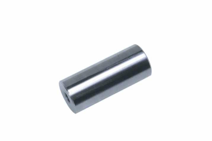
B-19 L +.001 +.002 A
Optional Set Screw (Mold maker to supply)
2.5" 4.5" D D CATALOG NUMBER L A B 1 SP100L2.5-SS 2.5 .62 3/8-16 SP100L3-SS 3 SP100L3.5-SS 3.5 SP100L4.5-SS 4.5 1-1/4 SP125L3-SS 3 .62 3/8-16 SP125L3.5-SS 3.5 SP125L4-SS 4 SP125L4.5-SS 4.5 1.5 SP150L3-SS 3 .62 3/8-16 SP150L3.5-SS 3.5 SP150L4-SS 4 SP150L4.5-SS 4.5 2 SP200L3-SS 3 .62 3/8-16 SP200L3.5-SS 3.5 SP200L4-SS 4 SP200L4.5-SS 4.5 SP200L5-SS 5 SP200L6-SS 6 3 SP300L5-SS 5 1.25 5/8-11 SP300L6-SS 6
All 2.5” and 4.5” long Threaded Support Pillars are tapped for a set screw enabling a second pillar to be attached as an extension.
L +.001 +.002 A B
1” Long Stainless Socket Head Cap Screw included.
Optional Set Screw (Mold maker to supply)
2.5" 4.5" D L +.001 +.002 D
M
All 2.5” and 4.5” long Threaded Support Pillars are tapped for a set screw enabling a second pillar to be attached as an extension.
CAD insertion point
410 Stainless Steel H 30-34 HRC
SUPPORT COLUMNS FOR DIE CAST DIES
SUPPORT COLUMN PUCKS
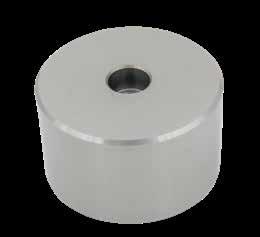
for retaining pin plates in die cast dies.
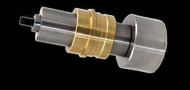
MOLD BASE COMPONENTS B-20
NOMINAL DIAMETER D ± .001 CATALOG NUMBER L +.001 +.002 C 1-1/2 1.496 SPH150L3 3 3/8-16 SPH150L3.5 3.5 SPH150L4 4 SPH150L4.5 4.5 SPH150L5 5 2 1.996 SPH200L3 3 3/8-16 SPH200L3.5 3.5 SPH200L4 4 SPH200L4.5 4.5 SPH200L5 5 D ± .01 L=.75 L=1.00 L=1.50 L=2.00 .750 SDB75L1* 1.000 SDB100L.75 SDB100L1 SDB100L1.5 1.500 SDB150L.75 SDB150L1 SDB150L1.5 2.000 SDB200L1 SDB200L1.5 2.500 SDB250L1 SDB250L1.5 SDB250L2 3.000 SDB300L1 SDB300L1.5 SDB300L2 D L ±.01 +.002 - .000 Counterbored for 3/8-16 SHCS
SDB75L1 (1/4-20 SHCS) Sized
* L = 1.125 for SDB75L1 Screw included.
except for
+.001 +.002 L ±.001 D .250 ± .0005 .751 Tubular Dowel clearance in SPH150 and SPH200 only C 48 ±2 HRC Pucks Support Column Guided Ejector Bushing Pucks Dowel Support Column Guided Ejector Bushing M AISI 4140 H 46-50 HRC M AISI 1018 CAD insertion point CAD insertion point
Guided Ejector Bushings sold separately on page B-14.
GUIDED SUPPORT PILLARS
Notes: Includes (1) Socket Head Cap Screw as shown in the chart. Guided Ejector Bushings are sold separately on page B-14.
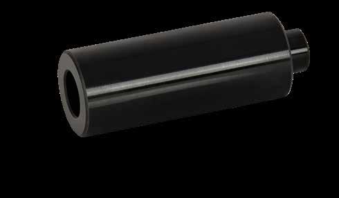
MOLD BASE COMPONENTS B-21
L +.001 +.002 Z –.005 –.010 D2 +.0000 –.0004 D1 +.000 –.001 NOMINAL DIAMETER D1 +.000 -.001 D2 +.0000 -.0004 Z -.005 -.010 CATALOG NUMBER L +.001 +.002 SHCS 3/4 .7495 .4685 .278 GESP75L2.5 2.5 1/4-20 x 2-3/4 GESP75L3 3 1/4-20 x 3-1/4 GESP75L3.5 3.5 1/4-20 x 3-3/4 GESP75L4 4 1/4-20 x 4-1/4 1 .9995 .4998 .309 GESP100L2.5 2.5 5/16-18 x 3 GESP100L3 3 5/16-18 x 3-1/2 GESP100L3.5 3.5 5/16-18 x 4 GESP100L4 4 5/16-18 x 4-1/2 GESP100L4.5 4.5 5/16-18 x 5 1-1/4 1.2495 .6873 .309 GESP125L3 3 5/16-18 x 3-1/2 GESP125L3.5 3.5 5/16-18 x 4 GESP125L4 4 5/16-18 x 4-1/2 GESP125L4.5 4.5 5/16-18 x 5 GESP125L5 5 5/16-18 x 5-1/2 1-1/2 1.4995 .7498 .372 GESP150L3.5 3.5 3/8-16 x 4 GESP150L4 4 3/8-16 x 4-1/2 GESP150L4.5 4.5 3/8-16 x 5 GESP150L5 5 3/8-16 x 5-1/2
M AISI 4140 H 58-62 HRC S Black
CAD insertion
Guided
Support Pillar Guided Ejector Bushing
Oxide
point
APPLICATION GUIDELINES
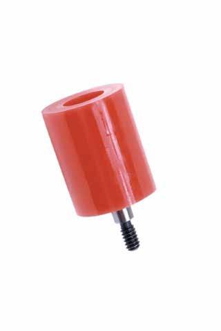
MOLD BASE COMPONENTS B-22
DEFLECTION D L APPROXIMATE SPRING PRESSURE 1/8” 1.06 1.12 520 lbs. 1/4” 1.12 1.00 790 lbs. CATALOG NUMBER DESCRIPTION US-100 1” Urethane Spring with 1/4ø x 1/2” SBLT .25ø +.01 -.00 D L 1.25 11/16 .125 #10-24 Thread Shore Hardness = 90A CAD insertion point M Solid Urethane
Cushion parting lines
• Maximum Mold Temperature: 150˚F (65˚C)
included.
• Stripper bolt
Blue Medium Duty
Full specifications are on page B-24.
Progressive’s Springs are manufactured from hardened alloy steel and are electrophoretic coated (“E-Coat”) to provide full coverage, uniform thickness, and corrosion resistance. The springs are color coded and striped for easy identification.
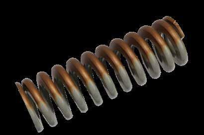
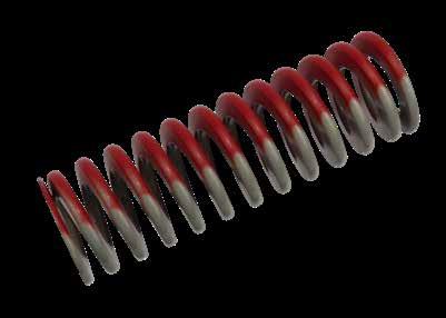
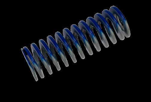
Red Medium-Heavy Duty
Full specifications are on page B-25.
Green Extra Heavy Duty
Gold Heavy Duty
To Order:
1. Choose the color above. Note that Red & Blue Springs have full details and item numbers on the pages noted and are typically in stock.
2. For green and gold springs, determine the Rod Diameter (ID) and Hole Diameter (OD) of the springs.
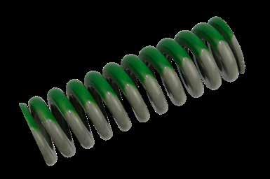
3. Determine the length and email Customer Service the specifications for pricing and delivery.
4. Other springs are available; contact Customer Service for more information
MOLD BASE COMPONENTS B-23
HOLE DIA ROD DIA FREE LENGTH
SPRINGS INCH STANDARD
M Chrome Vanadium Alloy Steel
MEDIUM DUTY: INCH STANDARD
Note: All pressure ratings are approximate and are subject to +10% over amounts shown for deflection.
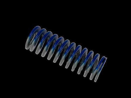
MOLD BASE COMPONENTS B-24
HOLE DIA OD DIA FREE LENGTH APPROX. LOAD AT 1/10” DELFEC. (LBS) LOAD AT 25% DELFEC. (LBS) LOAD AT 40% DELFEC. (LBS) 3/8 3/16 6.0 15.0 24.0 5.0 15.6 25.0 1.50 MS37L1.5 4.2 15.8 25.2 1.75 MS37L1.75 3.7 16.2 25.9 2.00 MS37L2 3.1 15.5 24.8 WIRE .039 X .070 2.50 MS37L2.5 2.6 16.3 26.0 3.00 MS37L3 2.1 15.8 25.2 12.00 MS37L12 0.6 18.0 28.8 1/2 9/32 1.00 MS50L1 11.0 27.5 44.0 1.25 MS50L1.25 8.2 25.6 41.0 1.50 MS50L1.5 6.8 25.5 40.8 1.75 MS50L1.75 6.0 26.3 42.0 2.00 MS50L2 5.5 27.5 44.0 2.50 MS50L2.5 4.5 28.1 45.0 3.00 MS50L3 3.5 26.3 42.0 3.50 MS50L3.5 3.0 26.3 42.0 4.50 MS50L4.5 2.3 25.9 41.4 5.50 MS50L5.5 2.0 27.5 44.0 WIRE .052 X .093 6.50 MS50L6.5 1.4 22.8 36.4 7.50 MS50L7.5 1.2 22.5 36.0 12.00 MS50L12 0.7 21.0 33.6 5/8 11/32 1.00 MS62L1 16.4 41.0 65.6 1.25 MS62L1.25 12.4 38.8 62.0 1.50 MS62L1.5 10.8 40.5 64.8 1.75 MS62L1.75 9.6 42.0 67.2 2.00 MS62L2 8.6 43.0 68.8 2.50 MS62L2.5 6.5 40.6 65.0 3.00 MS62L3 5.8 43.5 69.6 WIRE .069 X .109 3.50 MS62L3.5 5.0 43.8 70.0 4.00 MS62L4 4.4 44.0 70.4 12.00 MS62L12 1.5 45.0 72.0 3/4 3/8 1.00 MS75L1 32.0 80.0 128.0 1.25 MS75L1.25 25.6 80.0 128.0 1.50 MS75L1.5 20.0 75.0 120.0 1.75 MS75L1.75 17.6 77.0 123.2 2.00 MS75L2 15.0 75.0 120.0 2.50 MS75L2.5 12.0 75.0 120.0 3.00 MS75L3 10.1 75.8 121.2 3.50 MS75L3.5 8.3 72.6 116.2 4.00 MS75L4 7.5 75.0 120.0 4.50 MS75L4.5 6.4 72.0 115.2 5.00 MS75L5 6.0 75.0 120.0 5.50 MS75L5.5 5.5 75.6 121.0 6.00 MS75L6 5.0 75.0 120.0 WIRE .075 X .165 6.50 MS75L6.5 4.7 76.4 122.2 7.50 MS75L7.5 3.8 71.3 114.0 12.00 MS75L12 2.4 72.0 115.2 1 1/2 1.00 MS100L1 55.0 137.5 220.0 1.25 MS100L1.25 45.0 140.6 225.0 1.50 MS100L1.5 37.3 139.9 223.8 1.75 MS100L1.75 32.0 140.0 224.0 2.00 MS100L2 26.8 134.0 214.4 2.50 MS100L2.5 20.9 130.6 209.0 HOLE DIAMETER ROD DIAMETER FREE LENGTH CATALOG NUMBER APPROX. LOAD AT 1/10” DELFEC. (LBS) LOAD AT 25% DELFEC. (LBS) LOAD AT 40% DELFEC. (LBS) 1 1/2 3.00 MS100L3 17.1 128.3 205.2 3.50 MS100L3.5 14.5 126.9 203.0 4.00 MS100L4 12.5 125.0 200.0 4.50 MS100L4.5 11.0 123.8 198.0 5.00 MS100L5 9.6 120.0 192.0 5.50 MS100L5.5 8.8 121.0 193.6 6.00 MS100L6 8.0 120.0 192.0 WIRE .100 X .215 7.00 MS100L7 7.2 126.0 201.6 8.00 MS100L8 6.0 120.0 192.0 12.00 MS100L12 4.0 120.0 192.0 1-1/4 5/8 1.50 MS125L1.5 49.6 186.0 297.6 1.75 MS125L1.75 40.6 177.6 284.2 2.00 MS125L2 37.6 188.0 300.8 2.50 MS125L2.5 28.8 180.0 288.0 3.00 MS125L3 24.0 180.0 288.0 3.50 MS125L3.5 20.0 175.0 280.0 4.00 MS125L4 17.6 176.0 281.6 4.50 MS125L4.5 16.0 180.0 288.0 5.00 MS125L5 14.3 178.8 286.0 5.50 MS125L5.5 12.8 176.0 281.6 6.00 MS125L6 12.0 180.0 288.0 7.00 MS125L7 10.4 182.0 291.2 WIRE .115 X .285 8.00 MS125L8 8.8 176.0 281.6 10.00 MS125L10 7.2 180.0 288.0 12.00 MS125L12 6.0 180.0 288.0 1-1/2 3/4 2.00 MS150L2 53.0 265.0 424.0 2.50 MS150L2.5 42.7 266.9 427.0 3.00 MS150L3 36.0 270.0 432.0 3.50 MS150L3.5 30.0 262.5 420.0 4.00 MS150L4 24.9 249.0 398.4 4.50 MS150L4.5 23.0 258.8 414.0 5.00 MS150L5 21.0 262.5 420.0 5.50 MS150L5.5 18.5 254.4 407.0 6.00 MS150L6 17.0 255.0 408.0 7.00 MS150L7 15.3 267.8 428.4 WIRE .135 X .345 8.00 MS150L8 13.2 264.0 422.4 10.00 MS150L10 10.6 265.0 424.0 12.00 MS150L12 8.5 255.0 408.0 2 1 2.50 MS200L2.5 100.0 625.0 1000.0 3.00 MS200L3 83.0 622.5 996.0 3.50 MS200L3.5 67.7 592.4 947.8 4.00 MS200L4 60.0 600.0 960.0 4.50 MS200L4.5 53.0 596.3 954.0 5.00 MS200L5 47.0 587.5 940.0 5.50 MS200L5.5 40.5 556.9 891.0 6.00 MS200L6 39.0 585.0 936.0 7.00 MS200L7 31.2 546.0 873.6 WIRE .195 X .468 8.00 MS200L8 28.5 570.0 912.0 10.00 MS200L10 21.6 540.0 864.0 12.00 MS200L12 18.5 555.0 888.0
Recommended Deflection: 25% = Optimum Life 35% = Long Life 40% = Maximum Operating Deflection
Note: All pressure ratings are approximate and are subject to +10% over amounts shown for deflection.
SPRINGS
MEDIUM-HEAVY DUTY: INCH STANDARD
MOLD BASE COMPONENTS B-25
HOLE DIA ROD DIA FREE LENGTH Recommended Deflection: 20% = Optimum Life
= Long Life
= Maximum Operating Deflection
25%
30%
HOLE DIAMETER ROD DIAMETER FREE LENGTH CATALOG NUMBER APPROX. LOAD AT 1/10” DELFEC. (LBS) LOAD AT 20% DELFEC. (LBS) LOAD AT 30% DELFEC. (LBS) 3/8 3/16 1.00 HS37L1 8.4 16.8 25.2 1.25 HS37L1.25 7.3 18.3 27.4 1.50 HS37L1.5 6.7 20.1 30.2 1.75 HS37L1.75 5.8 20.3 30.5 2.00 HS37L2 5.0 20.0 30.0 WIRE .046 X .067 2.50 HS37L2.5 3.7 18.5 27.8 3.00 HS37L3 3.0 18.0 27.0 12.00 HS37L12 0.8 19.2 28.8 1/2 9/32 1.00 HS50L1 15.5 31.0 46.5 1.25 HS50L1.25 12.2 30.5 45.8 1.50 HS50L1.5 9.8 29.4 44.1 1.75 HS50L1.75 8.5 29.8 44.6 2.00 HS50L2 7.5 30.0 45.0 2.50 HS50L2.5 6.0 30.0 45.0 WIRE .061 X .093 3.00 HS50L3 5.1 30.6 45.9 3.50 HS50L3.5 4.0 28.0 42.0 12.00 HS50L12 1.1 26.4 39.6 5/8 11/32 1.00 HS62L1 30.0 60.0 90.0 1.25 HS62L1.25 21.5 53.8 80.6 1.50 HS62L1.5 19.0 57.0 85.5 1.75 HS62L1.75 16.8 58.8 88.2 2.00 HS62L2 15.5 62.0 93.0 2.50 HS62L2.5 11.5 57.5 86.3 3.00 HS62L3 10.0 60.0 90.0 WIRE .081 X .117 3.50 HS62L3.5 8.5 59.5 89.3 4.00 HS62L4 7.6 60.8 91.2 12.00 HS62L12 2.6 62.4 93.6 3/4 3/8 1.00 HS75L1 50.0 100.0 150.0 1.25 HS75L1.25 38.0 95.0 142.5 1.50 HS75L1.5 31.0 93.0 139.5 1.75 HS75L1.75 27.0 94.5 141.8 2.00 HS75L2 24.0 96.0 144.0 2.50 HS75L2.5 18.8 94.0 141.0 3.00 HS75L3 14.9 89.4 134.1 3.50 HS75L3.5 12.8 89.6 134.4 4.00 HS75L4 11.0 88.0 132.0 4.50 HS75L4.5 10.0 90.0 135.0 5.00 HS75L5 9.0 90.0 135.0 WIRE .093 X .156 5.50 HS75L5.5 8.0 88.0 132.0 6.00 HS75L6 7.5 90.0 135.0 12.00 HS75L12 3.5 84.0 126.0 1 1/2 1.00 HS100L1 82.7 165.4 248.1 1.25 HS100L1.25 65.3 163.3 244.9 1.50 HS100L1.5 53.8 161.4 242.1 1.75 HS100L1.75 46.1 161.4 242.0 2.00 HS100L2 40.0 160.0 240.0 2.50 HS100L2.5 32.2 161.0 241.5 HOLE DIAMETER ROD DIAMETER FREE LENGTH CATALOG NUMBER APPROX. LOAD AT 1/10” DELFEC. (LBS) LOAD AT 20% DELFEC. (LBS) LOAD AT 30% DELFEC. (LBS) 1 1/2 3.00 HS100L3 26.7 160.2 240.3 3.50 HS100L3.5 22.9 160.3 240.5 4.00 HS100L4 20.2 161.6 242.4 4.50 HS100L4.5 17.8 160.2 240.3 5.00 HS100L5 15.7 157.0 235.5 5.50 HS100L5.5 13.7 150.7 226.1 6.00 HS100L6 12.5 150.0 225.0 WIRE .115 X .218 7.00 HS100L7 10.9 152.6 228.9 8.00 HS100L8 9.6 153.6 230.4 12.00 HS100L12 6.5 156.0 234.0 1-1/4 5/8 1.50 HS125L1.5 114.4 343.2 514.8 1.75 HS125L1.75 100.8 352.8 529.2 2.00 HS125L2 83.8 335.2 502.8 2.50 HS125L2.5 62.4 312.0 468.0 3.00 HS125L3 51.2 307.2 460.8 3.50 HS125L3.5 44.0 308.0 462.0 4.00 HS125L4 38.1 304.8 457.2 4.50 HS125L4.5 32.9 296.1 444.2 5.00 HS125L5 30.0 300.0 450.0 5.50 HS125L5.5 26.4 290.4 435.6 6.00 HS125L6 25.0 300.0 450.0 7.00 HS125L7 21.0 294.0 441.0 WIRE .156 X .281 8.00 HS125L8 18.4 294.4 441.6 10.00 HS125L10 14.5 290.0 435.0 12.00 HS125L12 12.4 297.6 446.4 1-1/2 3/4 2.00 HS150L2 103.0 412.0 618.0 2.50 HS150L2.5 81.2 406.0 609.0 3.00 HS150L3 62.4 374.4 561.6 3.50 HS150L3.5 54.0 378.0 567.0 4.00 HS150L4 46.5 372.0 558.0 4.50 HS150L4.5 41.0 369.0 553.5 5.00 HS150L5 36.8 368.0 552.0 5.50 HS150L5.5 33.0 363.0 544.5 6.00 HS150L6 29.5 354.0 531.0 7.00 HS150L7 25.5 357.0 535.5 WIRE .187 X .312 8.00 HS150L8 22.0 352.0 528.0 10.00 HS150L10 17.6 352.0 528.0 12.00 HS150L12 14.4 345.6 518.4 2 1 2.50 HS200L2.5 118.4 592.0 888.0 3.00 HS200L3 93.0 558.0 837.0 3.50 HS200L3.5 78.2 547.4 821.1 4.00 HS200L4 66.4 531.2 796.8 4.50 HS200L4.5 60.0 540.0 810.0 5.00 HS200L5 53.4 534.0 801.0 5.50 HS200L5.5 49.0 539.0 808.5 6.00 HS200L6 45.0 540.0 810.0 7.00 HS200L7 37.4 523.6 785.4 WIRE .225 X .437 8.00 HS200L8 33.0 528.0 792.0 10.00 HS200L10 26.0 520.0 780.0 12.00 HS200L12 21.5 516.0 774.0
STRIPPER BOLTS
APPLICATION GUIDELINES
• Precise diameters exceed industry standards.
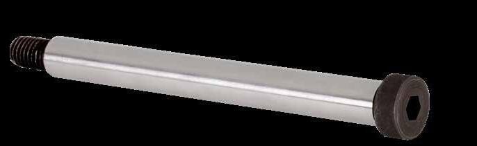
• Tighter tolerances for uniform plate-stop positioning.
• Stripper Bolt Bushings sold separately on page B-27.
MOLD BASE COMPONENTS B-26
H L E A ØD J THREAD D +.000 -.001 L ±.001 CATALOG NUMBER J A H E THREAD 3A .249 1 SBLT25L1 1/8 .37 .18 .37 #10-24 1.25 SBLT25L1.25 1.5 SBLT25L1.5 .311 1 SBLT31L1 5/32 .43 .21 .43 1/4-20 1.25 SBLT31L1.25 1.5 SBLT31L1.5 1.75 SBLT31L1.75 2 SBLT31L2 .374 1 SBLT37L1 3/16 .56 .25 .50 5/16-18 1.25 SBLT37L1.25 1.5 SBLT37L1.5 1.75 SBLT37L1.75 2 SBLT37L2 2.25 SBLT37L2.25 2.5 SBLT37L2.5 2.75 SBLT37L2.75 3 SBLT37L3 3.25 SBLT37L3.25 3.5 SBLT37L3.5 3.75 SBLT37L3.75 4 SBLT37L4 4.25 SBLT37L4.25 4.5 SBLT37L4.5 .499 1 SBLT50L1 1/4 .75 .31 .62 3/8-16 1.25 SBLT50L1.25 1.5 SBLT50L1.5 1.75 SBLT50L1.75 2 SBLT50L2 2.25 SBLT50L2.25 2.5 SBLT50L2.5 2.75 SBLT50L2.75 3 SBLT50L3 3.25 SBLT50L3.25 3.5 SBLT50L3.5 3.75 SBLT50L3.75 4 SBLT50L4 4.25 SBLT50L4.25 4.5 SBLT50L4.5 4.75 SBLT50L4.75 5 SBLT50L5 5.5 SBLT50L5.5 6 SBLT50L6 7 SBLT50L7 CAD insertion point M SCM440 H 42-48 HRC D +.000 -.001 L ±.001 CATALOG NUMBER J A H E THREAD 3A .624 1.25 SBLT62L1.25 5/16 .87 .37 .75 1/2-13 1.5 SBLT62L1.5 1.75 SBLT62L1.75 2 SBLT62L2 2.25 SBLT62L2.25 2.5 SBLT62L2.5 2.75 SBLT62L2.75 3 SBLT62L3 3.25 SBLT62L3.25 3.5 SBLT62L3.5 3.75 SBLT62L3.75 4 SBLT62L4 4.25 SBLT62L4.25 4.5 SBLT62L4.5 4.75 SBLT62L4.75 5 SBLT62L5 5.5 SBLT62L5.5 6 SBLT62L6 7 SBLT62L7 .749 1.5 SBLT75L1.5 3/8 1.00 .50 .87 5/8-11 1.75 SBLT75L1.75 2 SBLT75L2 2.25 SBLT75L2.25 2.5 SBLT75L2.5 2.75 SBLT75L2.75 3 SBLT75L3 3.25 SBLT75L3.25 3.5 SBLT75L3.5 3.75 SBLT75L3.75 4 SBLT75L4 4.25 SBLT75L4.25 4.5 SBLT75L4.5 4.75 SBLT75L4.75 5 SBLT75L5 5.5 SBLT75L5.5 6 SBLT75L6
SBLT75L7
SBLT75L8
7
8
STRIPPER BOLT BUSHINGS
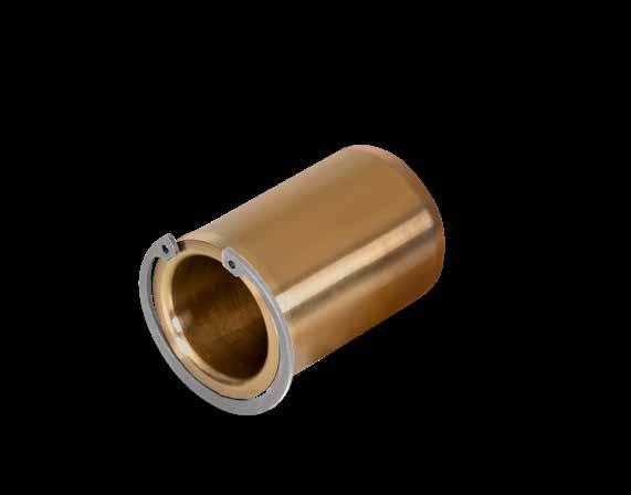
Replacement Retaining Rings are available. To order, specify the prefix of “RRB” before the ID.
Ex. RRB25 for a 1/4 ID ring. Note: SBB31L.62 utilizes an RRB37.
MOLD BASE COMPONENTS B-27
L OD ID OD CLR GW Retaining Ring (Included) Bushing GD BD GW Retaining Ring Bushing GD B CATALOG NUMBER ID +.000 -.001 OD +.000 -.001 L ±.005 GD +.005 -.000 GW +.003 -.000 OD CLR +.005 -.000 SBB25L.50 .251 .439 .500 .530 .029 .448 SBB31L.62 .312 .627 .625 .665 .039 .635 SBB37L.75 .376 .627 .750 .665 .039 .635 SBB50L1.00 .502 .753 1.000 .825 .046 .780 SBB63L1.50 .627 .878 1.500 1.000 .046 .950 SBB75L1.50 .752 1.003 1.500 1.091 .046 1.040 L OD ID OD CLR GW Retaining Ring (Included) Bushing GD BD GW Retaining Ring Bushing GD B
M
CAD
SAE841 Bronze
insertion point
TUBULAR DOWELS
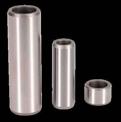
B-28
MOLD BASE COMPONENTS
Z ID OD L CATALOG NUMBER OD ±.0001 ID +.01 -.00 L +.00 -.02 Z CHAMFER TD37L.37 .3752 .260 .375 .04 x 20° TD37L.87 .875 .04 x 20° TD62L.50 .6252 .385 .500 .04 x 20° TD62L1.37 1.375 .08 x 20° TD62L1.87 1.875 .08 x 20° TD62L2.37 2.375 .08 x 20° TD75L.37 .7502 .510 .375 .04 x 20° TD75L.50 .500 .04 x 20° TD75L1.37 1.375 .08 x 20° TD75L1.87 1.875 .08 x 20° TD75L2.37 2.375 .08 x 20° TD75L2.87 2.875 .08 x 20° TD75L3.37 3.375 .08 x 20° TD75L3.87 3.875 .08 x 20° TD87L.50 .8752 .635 .500 .04 x 20° TD87L2.37 2.375 .08 x 20° TD87L2.87 2.875 .08 x 20° Z ID OD L Inch Standard Metric Standard CAD insertion point M Carbon Steel H 55 HRC M Carbon Steel H 55 HRC CATALOG NUMBER OD ±.003 ID +.25 -.00 L +.00 -.50 Z CHAMFER TDM10L20 10 6.2 20 1 x 20° TDM10L30 30 1 x 20° TDM14L30 14 8.5 30 1 x 20° TDM14L40 40 2 x 20° TDM14L50 50 2 x 20° TDM14L60 60 2 x 20° TDM14L70 70 2 x 20° TDM18L40 18 10.5 40 1 x 20° TDM18L60 60 1 x 20° TDM18L80 80 2 x 20° TDM18L100 100 2 x 20° TDM24L60 24 13 60 1 x 20° TDM24L80 80 2 x 20° TDM24L100 100 2 x 20°
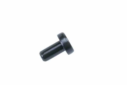
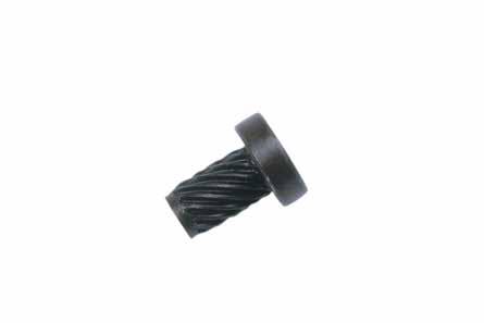
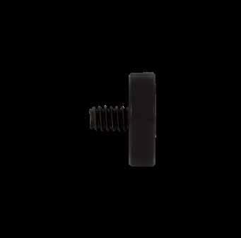
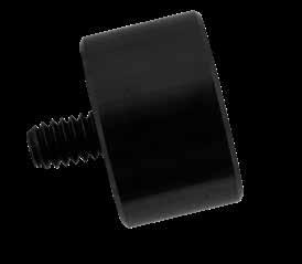
MOLD BASE COMPONENTS B-29
CATALOG NUMBER DESCRIPTION STP-2 Self-Tapping Stop Pins Self-Tapping Ø.62 .205 ±.005 .62 Drill Ø11/32 CATALOG NUMBER D +.000 -.015 T +.003 +.005 FLAT HEAD COUNTERBORE SD68 .687 .188 #10-24 SD100 1.000 .188 1/4-20 SD118 1.187 .188 1/4-20 SD168 1.687 .251 5/16-18 CATALOG NUMBER DESCRIPTION STP-1 Stop Pins Dowel Type Ø.62 .205 ± .005 .62 Ø.312 1/2” long Flat Head Screw included. H 42 ± 2 HRC .02 Chamfer L A T D H AISI 4037 H 40-44 HRC S Black Oxide M Pre-Hard Steel H Black Oxide CAD insertion point M 4140 H 40-44 HRC S Black Oxide CATALOG NUMBER D +.000 -.015 T +.002 +.000 SCREW SIZE (INCLUDED) SPC25X100 1.000 .250 1/4-20 x 5/8 Flat Head SPC37X100 1.000 .375 1/4-20 x 1/2 Socket Head SPC50X100 1.000 .500 1/4-20 x 5/8 Socket Head SPC50X168 1.688 .500 1/4-20 x 5/8 Socket Head SPC62X100 1.000 .625 1/4-20 x 3/4 Socket Head SPC75X100 1.000 .750 1/4-20 x 7/8 Socket Head SPC100X100 1.000 1.000 1/4-20 x 1-1/8 Socket Head SPC100X168 1.688 1.000 1/4-20 x 1-1/8 Socket Head CAD insertion point M 4140 H 40-44 HRC S Black Oxide 42 ± 2 HRC T D Socket Head Cap Screw Flat Head Cap Screw (SPC25X100) T D
SPACERS
PKO ™ EXTENSIONS HEX SERIES

PUCK SERIES
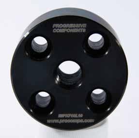
MOLD BASE COMPONENTS B-30
Ø11/4" PKO ROD PRESS PLATEN BCP 1/4” Pocket PKO ROD PRESS PLATEN BCP
CATALOG NUMBER INTERNAL THREAD EXTERNAL THREAD OVERALL L PH37L10 3/8-16 3/8-16 1.672 1.052 PH50L10 1/2-13 1/2-13 PH62L10 5/8-11 5/8-11 1.922 PH62L10-50 1/2-13 5/8-11 PH75L10 3/4-10 3/4-10 PH75L10-NT N/A 3/4-10 PH37L13 3/8-16 3/8-16 1.922 1.302 PH50L13 1/2-13 1/2-13 PH62L13 5/8-11 5/8-11 2.172 PH62L13-50 1/2-13 5/8-11 PH75L13 3/4-10 3/4-10 PH75L13-NT N/A 3/4-10 7/8" Hex 1" L Thread (Internal) Thread (External) Overall 30 ±2 HRC CAD insertion point Ø21/4" PKO ROD PRESS PLATEN BCP 1.375 (2) Ø2.00 Thread 1/4-20 SHCS(4) L 30 ±2 HRC (included) CATALOG NUMBER INTERNAL THREAD EXTERNAL THREAD OVERALL L PH37L15 3/8-16 3/8-16 2.172 1.552 PH50L15 1/2-13 1/2-13 PH50L15-NT N/A 1/2-13 PH62L15 5/8-11 5/8-11 2.422 PH75L15 3/4-10 3/4-10 PH75L15-NT N/A 3/4-10 PH37L18 3/8-16 3/8-16 2.422 1.802 PH50L18 1/2-13 1/2-13 PH50L18-NT N/A 1/2-13 PH62L18 5/8-11 5/8-11 2.672 PH75L18 3/4-10 3/4-10 PH75L18-NT N/A 3/4-10 CATALOG NUMBER THREAD L PKP37L10 3/8-16 1.052 PKP50L10 1/2-13 PKP62L10 5/8-11 PKP75L10 3/4-10 PKPL10-NT No Thread* PKP37L13 3/8-16 1.302 PKP50L13 1/2-13 PKP62L13 5/8-11 PKP75L13 3/4-10 PKPL13-NT No Thread* PKP37L15 3/8-16 1.552 PKP50L15 1/2-13 PKP62L15 5/8-11 PKP75L15 3/4-10 PKPL15-NT No Thread* PKP37L18 3/8-16 1.802 PKP50L18 1/2-13 PKP62L18 5/8-11 PKP75L18 3/4-10 PKPL18-NT No Thread*
“L” Dimensions: 1.052 = .875 (BCP) + .187 (Stop Pins) - .010 1.302 = .875 (BCP) + .187 (Stop Pins) + .250 (Insulator Plate) - .010 “L” Dimensions: 1.552 = 1.375 (BCP) + .187 (Stop Pins) - .010 1.802 = 1.375 (BCP) + .187 (Stop Pins) +.250 (Insulator Plate) - .010
*Mold maker machines thread on “NT” style to suit non-standard applications.
M AISI 4140 Pre-Hard H 28-32 HRC S Black Oxide
M
AISI 1018 S Black Oxide
ALIGNMENT LOCKS SECTION C
Bar Locks Bar Locks: Top Machining/X Bar Locks: Inserted Side Locks
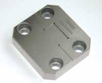
Prefix: BLB, BLG Prefix: BLBT, BLGT BLBX
BLN, BLS
SL, SLC, SLM Page: C-4 & C-5 Page: C-6 & C-7 Page: C-9 Page: C-10
X-Style Side Locks Top Locks: Internal Top Locks Guide Locks Prefix: SLX
TL, TLM
GL, GLM Page: C-11
Rectangular Taper Bar Locks Cavity Interlocks (Flat/Round) Taper Locks: Counterbored Taper Locks & Plates

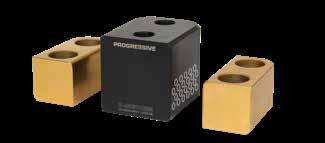
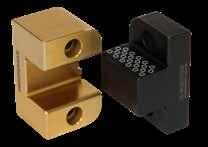
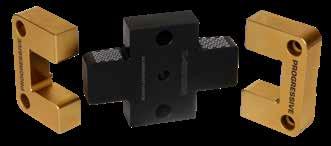
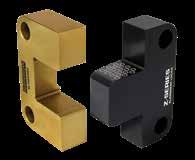
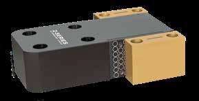
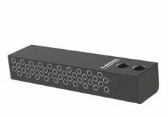
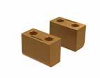
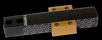
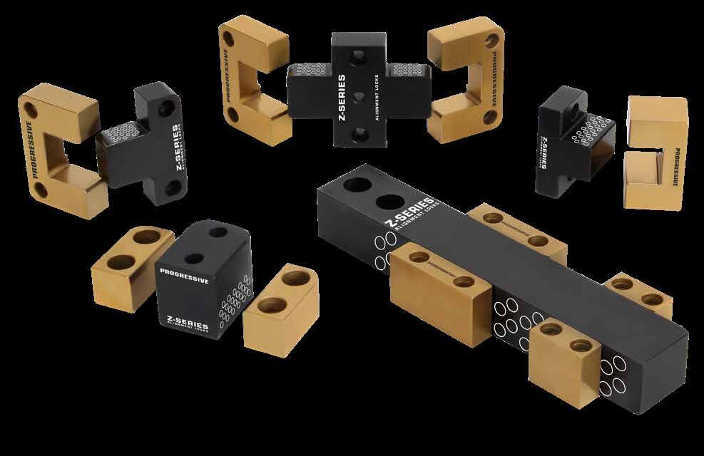
Prefix: MTBL, FTBL Prefix: CF, CFM, CRS, CRSM
MTL, FTL, TLP Page: C-15 Page: C-16 & C-17
TLC
Needle Bearing Locks Black Nitride Side Lock Side Locks: Graphite Plugged Side Locks: Steel Prefix: SLR, SLRM, TLR
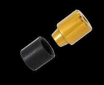
SL
SLPM
SLS, SLMS Page: C-20 & C-21
Prefix:
Prefix:
Prefix:
Prefix:
Page: C-12 Page: C-14
Prefix:
Prefix:
Prefix:
Prefix:
Prefix:
Page: C-22 Page: C-23 Page: C-24
ALIGNMENT LOCKS PERFORMANCE TESTING
Progressive Components regularly tests products through independent testing facilities nationwide.
Before launching of the Z-Series™ Alignment Locks, Progressive contracted Element Materials Technology to provide a thorough mold lock Performance Evaluation:

“Element Materials Technology has conducted independent life cycle testing of mold interlocks since 1999. The processes with fixtures and cycling were established to simulate use in the molding environment, but more severe loads were used to accelerate the failures at 4400 lbs of pressure. The locks tested have been from Progressive as well as other standard lock distributors in the US and Asia, plus several additional material and treatment combinations were tested for comparison.”
It was determined that the Progressive Components Z-Series Alignment Locks exceeded the 2-million cycle mark, and still displayed no measurable signs of wear of any type.
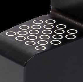

“During the past few years, over 21 different tests were performed with the purpose of cycling until failure occurred. At no time during our tests over the years have we seen cycle performance at the level of this new design, represented as PRO in the chart below.”
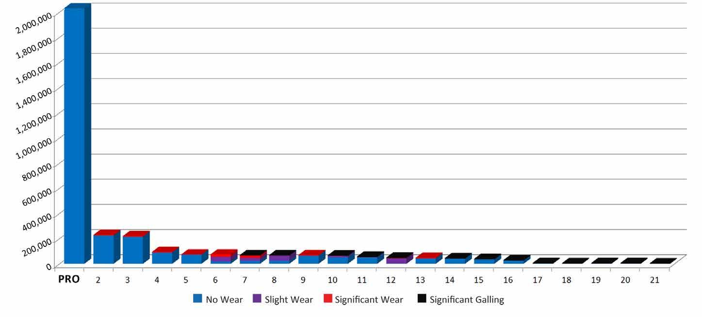
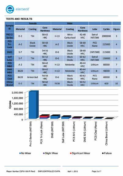
With the industry’s widest selection of sizes in stock and competitively priced, specifying alignment locks from Progressive Components means your molds will have unmatched protection from damage and downtime.

ALIGNMENT LOCKS C-1
Learn more at procomps.com/z-series. All catalog pages are online for forwarding to suppliers, customers, etc. ALIGNMENT LOCKS TOP LOCKS Z-SERIES CATALOG NUMBER T +.00 -.05 W +.00 -.01 A +.00 -.05 B +.00 -.05 C D .002/.008 Clearance Per Side S1 ±.25 S2 ±.25 R Pocket Radius Z Chamfer SHCS TLM26X35 26 35 25 15 17 11 13 23 8 M: M5 x 16 F: M5 x 25 TLM30X45 30 45 25 15 17 15 15 30 8 M: M6 x 18 F: M6 x 25 TLM36X55 36 55 30 20 21.5 20 18 37.5 8 M: M8 x 22 F: M8 x 35 TLM36X75 36 75 35 20 26 30 18 52 8 1.5 M: M10 x 25 F: M10 x 35 TLM45X100 45 100 60 20 42 40 22.5 70 8 1.5 M: M10 x 25 F: M10 x 65 Screws included. CATALOG NUMBER T +.000 -.002 W +.0000 -.0004 A +.000 -.002 B +.000 -.002 C D .0001/.0003 Clearance Per Side S1 .01 S2 .01 R Pocket Radius Z Chamfer SHCS TL50X100 .500 1.000 .500 .375 .30 .375 .250 .688 .188 .03 M: #6-32 x 1/2” F: #6-32 x 5/8” TL62X125 .625 1.250 .625 .500 .41 .438 .312 .875 .250 .03 M: #6-32 x 5/8” F: #6-32 x 3/4” TL75X125 .750 1.250 .625 .500 .38 .438 .375 .875 .250 .04 M: #8-32 x 5/8” F: #8-32 x 3/4” TL87X150 .875 1.500 .875 .750 .57 .500 .437 1.000 .250 .04 M: #8-32 x 7/8” F: #8-32 x 1” TL100X150 1.000 1.500 .875 .375 .57 .500 .500 1.000 .250 .04 M: #10-32 x 1/2” F: #10-32 x 1” TL100X200 1.000 2.000 1.125 .750 .75 .750 .500 1.375 .375 .04 M: #10-32 x 7/8” F: #10-32 x 1-1/8” TL112X200 1.125 2.000 .875 .625 .50 .750 .563 1.375 .375 .04 M: 1/4-20 x 3/4” F: 1/4-20 x 1” TL112X300 1.125 3.000 1.500 .750 .87 1.125 .563 2.250 .500 .04 M: 1/4-20 x 7/8” F: 1/4-20 x 1-5/8” TL150X250 1.500 2.500 1.375 .625 .85 1.000 .750 1.750 .375 .04 M: 1/4-20 x 3/4” F: 1/4-20 x 1-1/2” TL175X300 1.750 3.000 1.250 .875 .75 1.125 .875 2.250 .500 .06 M: 5/16-18 x 1” F: 5/16-18 x 1-1/4” TL200X350 2.000 3.500 1.750 .750 1.07 1.500 1.000 2.500 .500 .06 M: 3/8-16 x 7/8” F: 3/8-16 x 2” R (4) C D S1 R W S2 Z CAD nsertion poin Screws included. For custom Locks, refer to the templates in section X. Note: 500°F max operating temperature. Note: 260°C max operating temperature. Female: M D-2 H Core: 58-62 HRC, Surface: 80 HRC S Titanium Nitride Coated Male: M H-13 H Core: 42-48 HRC, Surface: 70 HRC S Black Nitride Inch Standard Metric Standard ALTERNATIVE CONFIGURATIONS AVAILABLE ONLINE DATA US Patent No. 8,821,144 and others pending
ALIGNMENT LOCKS
Progressive’s Alignment Locks have been advanced to outperform other styles. This is achieved through a combination of engagement geometry, particulate capturing rings, materials and treatments, and lubrication. Benefits of the Z-Series Alignment Locks include: Longevity that far surpasses others, confirmed by extensive independent lab testing as well as monitoring performance in harsh, ‘real world’ conditions. Exclusive features maintain clean and consistent lubrication. Bar Lock, Guide Lock, Side Lock, X-Style Side Lock and Top Lock styles available with the features below, and Cavity Locks (Round and Flat), Tapered Bar Locks, and C’Bored Taper Locks are also available with the Z-Series treatments.
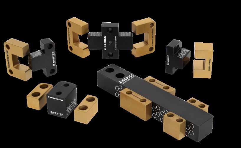
A Engagement Ramp: A fine finish radial lead-in for smooth lifting upon engagement of the mold halves.
B Particle Rings: Particle rings on the width of the male locks trap material and debris to avoid “picking up” or galling of the alignment surface.
C Longer Engagement: Using the maximum allowable engagement area on all locks surpasses previously-established industry standards.
D Arced Relief: Reduces the possibility of parts sticking to the lock at the bottom of the mold.
E Rounded Edges: A larger radius for all protruding surfaces to eliminate operator “reach in” injury.
F Pry Slot Lead-In: Expanded the entry of pry slots to ease removal.
Premium Materials: Males: H-13, 42-48 HRC, Surface: 70 HRC; Females: D-2, 58-62 HRC, Surface: 80 HRC.
Note: 500°F (260°C) max operating temperature.
Lubrication & Maintenance:
• Non-drying, non-hardening food grade grease is applied to all areas, including the particle rings.
• For production, install the locks and wipe down the outside of the locks only; maintain the grease on the mating surfaces and within the rings as provided.
ALIGNMENT LOCKS C-2
D C D C B
F A E US Patent No. 8,821,144 and others pending.
SIDE/TOP/GUIDE LOCK SELECTION GUIDE
Refer to the chart below to match the correct alignment lock for the corresponding mold size and weight of the B-Side and press platen, using four locks per mold. Clean and lubricate lock every 100,000 cycles, and prevent corrosion during mold storage.
SL37X100, SL50X125 SL50X150, SL50X200 SLS62X150, SLS62X200 SLR50X125,SLR50X150
SLM16X50, SLPM16X20 SLPM16X40, SLPM20X25
SLMS13X38 SLMS16X50
11 X 16 X 10
SL50X125, SL50X150 SL50X200,SLS62X150 SLS62x200, SLS75X300 SLS75X400, SLR50X150 SLR50X200
SL50X150, SL50X200 SL75X300, SLS112X500 SLS75X300, SLS75X400
SLR100X400
SLM16X50, SLMS19X75
SLPM25X32, SLPM25X63 SLPM32X40, SLPM32X80
SLPM40X100
SLM19X75, SLM19X100
BAR LOCK SELECTION GUIDE
ALIGNMENT LOCKS C-3
US Patent No. 8,821,144 and others pending. RECOMMENDED MAX MOLD SIZE (LXWXH) SIDE LOCKS METRIC SIDE LOCKS GUIDE LOCKS TOP LOCKS TOTAL MAX WEIGHT B SIDE + PRESS PLATEN (LBS/KG) RTI AND MOLDS 8
SMALLER
X 8 X 8 AND
SLPM20X50,
GL100X150 GLM25X45 TL75X75, TLM20X20 TL50X100, TL62X125 TL75X125, TLM26X35 TLR87X150 2,000 / 900
SLPM40X50,
SLMS19X100 GL100X150 GL150X250 GLM25X45 TL62X125, TL75X125 TL100X100, TLM25X25 TLM26X35 TLR87X150, TLR112X200 5,000 / 2,300
24
16
16 X
X
SLR75X300,
SLMS25X125 SLPM50X56, SLPM50X112 SLRM32X63 SLRM40X100 GL150X250 GLM40X65 TL75X125, TL87X150 TL137X137, TLM32X32 TLM26X35, TLM30X45 TLR112X200 TLR150X250 7,000 / 3,200 28 X 34 X 24 SL75X300, SLS112X500 SLM19X75, SLM19X100 GL200X350 GL150X250 GLM40X65 TL100X150, TL100X200 TL112X200, TL112X300 TLM26X35, TLM30X45 10,000 / 4,500 32 X 40 X 28 SL100X400 SLM25X125 GL200X350 GLM40X65 TL112X200, TL112X300 TLM36X55, TLM36X75 15,000 / 6,800 42 X 48 X 34 SL125X500 GL250X450 GLM50X90 TL150X250, TL175X300 TLM36X55, TLM36X75 20,000 / 9,000 48 X 52 X 38 SL150X600 GL250X450 TL175X300, TL200X350 TLM45X100 26,000 / 11,800
MALE BAR CATALOG NUMBER GUIDE CATALOG NUMBER BAR LOCK ENGAGEMENT TOTAL MAX WEIGHT SUPPORTED (LBS/KG) BLB100L4 BLG100L1.3, BLG100L1.8 BLG100L2.3, BLG100L2.8 2.50 10,000 / 4,500 BLBX137L5 BLGT137L1.3, BLGT137L1.8 3.00 BLB100L6 BLG100L1.3, BLG100L1.8 BLG100L2.3, BLG100L2.8 4.50 BLBT137L6 BLGT137L1.3, BLGT137L1.8 BLBM25L125 BLGM25L27, BLGM25L36 89mm BLB125L5 BLG125L1.3, BLG125L1.8 BLG125L2.3, BLG125L2.8 3.00 15,000 / 6,800 BLBX162L6 BLGT162L1.3, BLGT162L2.3 3.50 BLB125L9 BLG125L1.3, BLG125L1.8 BLG125L2.3, BLG125L2.8 7.00 BLBT162L9 BLGT162L1.3, BLGT162L2.3 BLBM32L160 BLGM32L36, BLGM32L46 114mm BLB137L6 BLG137L1.8, BLG137L2.3 BLG137L2.8, BLG137L3.3, BLG137L3.8 3.50 20,000 / 9,000 BLBX200L7 BLGT200L1.8 & BLGT200L2.8 4.50 BLB137L11 BLG137L1.8, BLG137L2.3 BLG137L2.8, BLG137L3.3, BLG137L3.8 8.50 BLBT200L11 BLGT200L1.8 & BLGT200L2.8 BLBM38L250 BLGM38L46, BLGM38L76 194 mm 26,000 / 11,800 BLB150L8 BLG150L1.8, BLG150L2.3 BLG150L2.8, BLG150L3.3, BLG150L3.8 4.50 BLB150L16 12.50 BLN150L8 BLG150L1.8, BLG150L2.3 BLG150L2.8, BLG150L3.3, BLG150L3.8 3.75 BLN250L10 BLG250L4.3 5.00 50,000 / 22,500 BLN350L13 BLG350L4.8 6.00 75,000 / 34,000
ALIGNMENT LOCKS
BAR LOCKS BARS-SIDE MACHINE STYLE
M H-13 H Core: 42-48 HRC, Surface 70 HRC S Black Nitride
CAD insertion point
Bars are sold individually and include 2 screws.
Metric Standard
M H-13 H Core: 42-48 HRC, Surface 70 HRC S Black Nitride
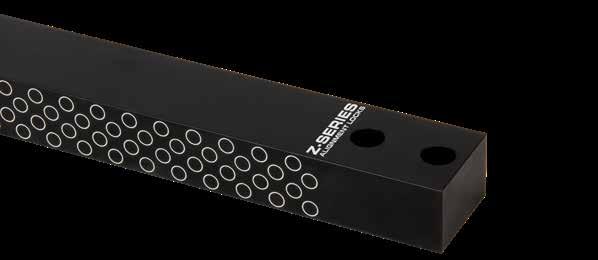
Bars are sold individually and include 2 screws.
ALTERNATIVE CONFIGURATIONS AVAILABLE
• Guides are sold separately on page C-5.
• Bars can be cut to length and/or have radii machined. Refer to page C-7 for details.
• Made-to-order Bar Locks can be quoted using the templates at procomps.com.
C-4
L
S2 T W P
S1
CATALOG NUMBER L T +.000 - .005 W +.0000 - .0005 P MINIMUM POCKET LENGTH S1 ±.01 S2 ±.01 SHCS BLB100L4 3.88 1.000 1.000 1.38 .38 .69 5/16-18 x 1-1/4 BLB100L6 6.00 BLB125L5 4.88 1.250 1.500 1.88 .50 1.00 3/8 - 16 x 1-1/2 BLB125L9 8.88 BLB137L6 5.88 1.375 2.000 2.38 .50 1.38 3/8 - 16 x 1-1/2 BLB137L11 10.88 BLB150L8 7.88 1.500 3.000 3.38 .63 2.00 1/2 - 13 x 1-3/4 BLB150L16 15.88 CATALOG NUMBER L T +.0 - .1 W +.00 - .01 P MINIMUM POCKET LENGTH S1 ±.25 S2 ±.25 SHCS BLBM25L125 125 25 25 36 10 18 M8-1.25 x 30 BLBM32L160 160 32 38 46 12.5 25 M10-1.5 x 35 BLBM38L250 250 38 50 56 15 30 M12-1.75 x 45
Inch Standard
US Patent No. 8,821,144 and others pending.
PW Tolerances: Standard Bars: +.0003/+.0006 (+.007/+.015mm)
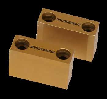
Inserted Bars: +.0010/+.0015 (+.025/+.038mm)
BAR LOCKS
GUIDES-SIDE MACHINE STYLE
ALTERNATIVE CONFIGURATIONS AVAILABLE
• Side Machine Bars are sold separately on page C-4. Inserted Bar Locks are sold on page C-9.
• Guides can have 2 or 4 radii machined. Refer to page C-7 for details.
• Made-to-order Guides can be quoted using the templates at procomps.com.
APPLICATION GUIDELINES
• Guides are sold in pairs. Each set includes 2 Guides and 4 Screws.
• Refer to page C-8 for application guidelines.
ALIGNMENT LOCKS C-5
M D-2 H Core: 58-62 HRC, Surface 80 HRC S Titanium Nitride Coated M D-2 H Core: 58-62 HRC, Surface 80 HRC S Titanium Nitride Coated CAD insertion point L S2 S1 T C PW CATALOG NUMBER T +.000 - .005 L +.000 - .005 C +.0000 - .0003 S1 ±.01 S2 ±.01 PW SHCS USE WITH BLG100L1.3 1.000 1.310 .500 .25 .75 2.000 #10-32 x 1-1/4 BLB100L4 & BLB100L6 BLG100L1.8 1.810 1.12 BLG100L2.3 2.310 1.25 BLG100L2.8 2.810 1.625 BLG125L1.3 1.250 1.310 .625 .31 .75 2.750 1/4-20 x 1-1/2 BLB125L5 & BLB125L9 BLG125L1.8 1.810 1.12 BLG125L2.3 2.310 1.25 BLG125L2.8 2.810 1.62 BLG137L1.8 1.375 1.810 .750 .37 1.12 3.500 5/16-18 x 1-1/2 BLB137L6 & BLB137L11 BLG137L2.3 2.310 1.25 BLG137L2.8 2.810 1.62 BLG137L3.3 3.310 2.25 BLG137L3.8 3.810 2.50 BLG150L1.8 1.500 1.810 1.000 .50 1.00 5.000 (6.000 for BLN150) 3/8-16 x 1-3/4 BLN150L8, BLB150L8, & BLB150L16 BLG150L2.3 2.310 1.50 BLG150L2.8 2.810 1.62 BLG150L3.3 3.310 2.25 BLG150L3.8 3.810 2.50 BLG250L4.3 2.500 4.310 1.250 .62 3.00 7.500 1/2-13 x 2-3/4 BLN250L10 BLG350L4.8 3.500 4.810 1.750 .87 3.25 9.500 5/8-11 x 3-3/4 BLN350L13 Inch Standard Metric Standard US Patent No. 8,821,144 and others pending.
CATALOG NUMBER T +.0 - .1 L +.0 - .1 C +.000 - .007 S1 ±.25 S2 ±.25 PW SHCS USE WITH BLGM25L27 25 27 12 6 14 49 M4-0.7 x 25 BLBM25L125 BLGM25L36 36 20 BLGM32L36 32 36 16 8 20 70 M6-1.0 x 35 BLBM32L160 BLGM32L46 46 30 BLGM38L46 38 46 22 11 24 94 M10-1.5 x 40 BLBM38L250 BLGM38L76 76 54
ALIGNMENT LOCKS
BAR LOCKS
BARS-TOP MACHINE STYLE
H Core: 42-48 HRC, Surface 70 HRC S Black Nitride
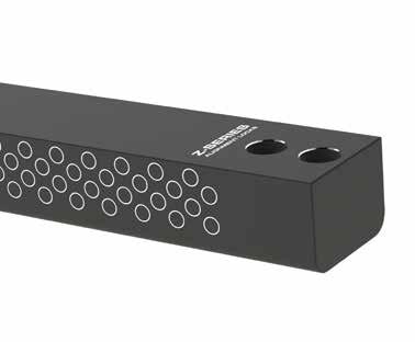
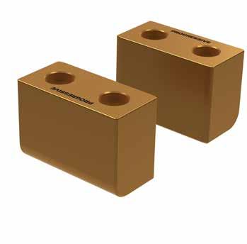
Bars are sold individually and include 2 screws.
GUIDES-TOP MACHINE STYLE
C-6
US Patent No. 8,821,144 and others pending. L S1 S2 R T W P M
CATALOG NUMBER L T +.000 - .005 W +.0000 - .0005 P MINIMUM POCKET LENGTH R POCKET RADIUS S1 ±.01 S2 ±.01 SHCS BLBT137L6 6.00 1.375 1.625 1.375 .250 .38 .69 5/16-18 x 1-1/2 BLBT162L9 8.88 1.625 2.250 1.875 .312 .50 1.00 3/8-16 x 1-3/4 BLBT200L11 10.88 2.000 3.000 2.375 .375 .63 1.25 1/2-13 x 2-1/4
PW L S2 S1 T C R M D-2 H Core:
HRC,
CAD insertion point CATALOG NUMBER T +.000 - .005 L +.000 - .005 C +.0000 - .0003 R POCKET RADIUS S1 ±.01 S2 ±.01 PW +.0003 +.0006 SHCS USE WITH BLGT137L1.3 1.375 1.310 1.000 .250 .50 .75 3.625 #10-32 x 1-1/2 BLBT137L6 BLGT137L1.8 1.810 1.12 BLGT162L1.3 1.625 1.310 1.125 .312 .56 .75 4.500 1/4-20 x 1-3/4 BLBT162L9 BLGT162L2.3 2.310 1.25 BLGT200L1.8 2.000 1.810 1.375 .375 .69 1.12 5.750 5/16-18 x 2-1/4 BLBT200L11 BLGT200L2.8 2.810 1.62 Guides are sold in pairs. Each set includes 2 Guides and 4 Screws. CAD insertion point
H-13
58-62
Surface 80 HRC S Titanium Nitride Coated
M H-13 H Core: 42-48 HRC, Surface 70 HRC S Black Nitride
BAR LOCKS X-STYLE
Bars are sold individually and include 2 screws. Top machine style Guides are sold on page C-6.
MOLD-READY SPECIALS
Guides are sized
To Order:
• For cut-to-length Side Machine Bars (pg C-4) or Top Machine Bars (pg C-6), specify the prefix of the Bar and the finished length. Ex. BLB100L4.56. (See max CTL length in the chart below.)
• For Side Machine Bars cut to length with pocket radii with sizes shown in the chart,specify the size, length and add “-R” suffix. Ex. BLB100L4.56-R.
• For Side Machine Bars with pocket radii in standard lengths, add “-R” to the end of the catalog number. Ex. BLB100L6-R.
• For Side Machine Guides with corner radii on both parts, add “-R” to the end of the catalog number. Ex. BLG150L2.8-R.
APPLICATION GUIDELINES
• For Guides, the pocket radii are machined on opposing sides as shown above.

• Bar lengths are modified from standards and radii (for Side Machine Bars) are machined on the pocket side to maintain the integrity of the material and treatment on the engagement side.
Original:
Note: Mold-Ready Specials must have a minimum quantity of (2) Bars or (2) sets of Guides per order.
ALIGNMENT LOCKS C-7
US Patent No. 8,821,144 and others pending. L S R T W P2 P3 P1
CATALOG NUMBER L T +.000 - .005 W +.0000 - .0005 P1 MINIMUM POCKET LENGTH P2 MIN. PLATE THICKNESS P3 MIN. PLATE THICKNESS R POCKET RADIUS S ±.01 SHCS BLBX137L5 4.63 1.375 1.625 1.375 1.88 1.38 .250 .69 5/16-18 x 1-1/2 BLBX162L6 5.63 1.625 2.250 1.875 2.38 1.38 .312 1.00 3/8-16 x 1-3/4 BLBX200L7 7.13 2.000 3.000 2.375 2.88 1.88 .375 1.25 1/2-13 x 2-1/4
P CTL Max cut length specified by customer. ENGAGEMENT SIDE BLB100L4.56-R R R R Original: BLB100L6 R BAR CATALOG PREFIX CTL MAX R POCKET RADIUS BLB100 4.62 .25 BLB125 7.00 .31 BLB137 8.50 .37 BLBT137 4.62 N/A BLB150 12.50 .50 BLBT162 7.00 N/A BLBT200 8.50 N/A BLBM25 89mm 6 mm BLBM32 114mm 8 mm BLBM38 194mm 10 mm GUIDE CATALOG PREFIX R POCKET RADIUS BLG100 .18 BLG125 .25 BLG137 .31 BLG150 .37 BLG250 .37 BLG350 .50 BLGM25 5mm BLGM32 6mm BLGM38 7mm
P CTL Max cut length specified by customer. ENGAGEMENT SIDE BLB100L4.56-R R R R
BLB100L6 R
CAD insertion point
ALIGNMENT LOCKS
BAR LOCKS APPLICATIONS
The minimum pocket length (P) is shown below in different applications.
C-8
Stack Mold Application Floating Plate Application Stripper
P P R P PLATEN TCP A PLATE Three Plate Application
Plate Application
B Plate A Plate X Plate US Patent No. 8,821,144 and others pending.
M 4140 H Core: 36-40 HRC, Surface 70 HRC S Black Oxide
M H-13 H Core: 42-48 HRC, Surface 70 HRC S Black Nitride
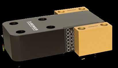
BAR LOCKS INSERTED
MALE BAR LOCK ASSEMBLIES
Each catalog number includes (1) Bar and (2) Inserts with screws. Guides are sold separately on page C-5.
INSERTS
ALIGNMENT LOCKS C-9
Bar:
Inserts:
L S2 S1 W1 S3 W2 PW T C R Inserts P NL NH S5 S4 .315 +.0000 -.0005 .375 1/4-20 SHCS BLS150 (2) On Center BLS250/350 (4) Insert Pocket CATALOG NUMBER T +.000 - .005 W1 +.0000 - .0005 W2 L C REF S1 ±.01 S2 ±.01 S3 ±.01 R POCKET RADIUS P MINIMUM POCKET LENGTH SHCS BLN150L8 1.500 4.000 4.000 +.000 -.002 7.75 3.75 1.00 2.00 2.25 .75 4.00 1/2-13 x 1-3/4 BLN250L10 2.500 5.000 5.000 +.000 -.002 10.38 5.00 1.25 3.25 3.25 1.00 5.38 5/8-11 x 2-3/4 BLN350L13 3.500 6.000 6.000 +.000 -.003 12.88 6.00 1.50 4.00 3.50 1.00 6.88 3/4-10 x 3-3/4
CATALOG NUMBER NH +.000 - .005 NL +.000 - .002 S4 ±.01 S5 ±.01 BLS150 1.440 2.999 1.75 BLS250 2.440 3.999 2.25 1.50 BLS350 3.375 4.999 3.00 2.50 Inserts sold individually and include screws. NL NH S5 S4 .315 +.0000 -.0005 .375 1/4-20 SHCS BLS150 (2) On Center BLS250/350 (4) Insert Pocket CAD insertion point M H-13 H Core: 42-48 HRC, Surface 70 HRC S Black Nitride US Patent No. 8,821,144 and others pending.
ALIGNMENT LOCKS
SIDE LOCKS Z-SERIES
ALTERNATIVE CONFIGURATIONS AVAILABLE
• To order Shuttle Mold sets or special male/female configurations, refer to page C-11.
• Made-to-order Side Locks can be quoted using the templates at procomps.com.
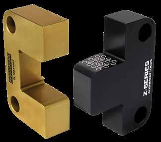
C-10
CATALOG NUMBER T +.000 -.002 W +.0000 -.0004 A +.000 -.002 B +.000 -.002 C D .0001/.0003 CLEARANCE PER SIDE H +.000 -.004 R POCKET RADIUS S1 ±.01 S2 ±.01 S3 ±.01 Z SHCS SL37X100 .375 1.000 1.125 .875 .62 .500 2.000 .187 .25 .25 .25 .015 #10-32 x 1/2 SL50X125 .490 1.250 1.125 .875 .68 .500 2.000 .187 .25 .25 .25 .03 #8-32 x 5/8 SL50X150 .500 1.500 .875 .875 .56 .563 1.750 .187 .25 .25 .25 .03 #8-32 x 5/8 SL50X200 .500 2.000 1.375 .875 .86 .750 2.250 .187 .31 .31 .31 .03 #10-32 x 5/8 SLC62X150 .620 1.500 .870 .870 .41 .500 1.74 .187 .28 .28 .43 .03 1/4-20 x 3/4 SLC62X200 .620 2.000 .870 .870 .41 .680 1.74 .187 .37 .37 .43 .03 1/4-20 x 3/4 SL75X300 .750 3.000 1.875 .875 1.18 1.250 2.750 .250 .37 .37 .37 .03 1/4-20 x 3/4 SLC75X300 .745 3.000 1.370 1.360 .68 1.000 2.73 .187 .37 .68 .68 .03 3/8-16 x 1 SL100X400 1.000 4.000 2.375 1.375 1.43 1.500 3.750 .500 .50 .50 .50 .03 3/8-16 x 1 SL125X500 1.250 5.000 2.875 1.375 1.75 2.000 4.250 .500 .62 .62 .62 .03 1/2-13 x 1-1/4 SL150X600 1.500 6.000 2.875 1.375 1.87 2.500 4.250 .500 .62 .62 .62 .03 1/2-13 x 1-1/2 CATALOG NUMBER T +.00 -.05 W +.00 -.01 A +.00 -.05 B +.00 -.05 C D .002/.008 CLEARANCE PER SIDE H + 0.0 - 0.1 R POCKET RADIUS S1 ±.25 S2/S3 ±.25 Z SHCS SLM16X50 16 50 21.5 21.5 13 17 43 5 8 11 .8 M6-1.0 x 18 SLM19X75 19 75 36 36 22.5 25 72 5 12.5 18 .8 M10-1.5 x 20 SLM19X100 19 100 45 45 30 35 90 5 15 22 .8 M10-1.5 x 20 SLM25X125 25 125 45 45 28.7 35 90 5 20.5 22 .8 M10-1.5 x 25 D B R H A C S2 S1 SHCS T W Z S3 Inch Standard Metric Standard CAD insertion point Female: M D-2 H Core: 58-62 HRC, Surface: 80 HRC S Titanium Nitride Coated Male: M H-13 H Core: 42-48 HRC, Surface: 70 HRC S Black Nitride Screws included. Screws included. US Patent No. 8,821,144 and others pending.
X-STYLE SIDE LOCKS Z-SERIES
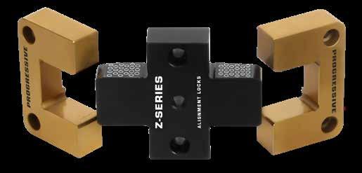
Females (2): M D-2 H Core: 58-62 HRC, Surface: 80 HRC S Titanium Nitride Coated
Male: M H-13 H Core: 42-48 HRC, Surface: 70 HRC S Black Nitride
ALTERNATIVE CONFIGURATIONS AVAILABLE
• Made-to-order Side Locks can be quoted using the templates at procomps.com.
SHUTTLE MOLD SETS
Examples of Shuttle Mold configurations:
2 Female Inserts : 1 Male Insert
To order, specify “-SF” after the catalog number of the lock.
Examples: SL50X200-SF GL100X150-SF TL75X125-SF
TL50X100-R-SF CF31X62-SF CRSM08-SF
2 Male Inserts : 1 Female Insert
To order, specify “-SM” after the catalog number of the lock.
Example: SL75X300-SM GL250X450-SM TL112X200-SM
TL150X250-R-SM CF31X62-SM CRSM08-SM
Individual males and females and special configurations (Ex. 4M:1F) are available. Contact Customer Service for pricing and availability.
ALIGNMENT LOCKS C-11
CATALOG NUMBER T +.000 -.002 W +.0000 -.0004 X +.000 -.002 A +.000 -.002 C ±.01 D .0001/.0003 CLEARANCE PER SIDE R POCKET RADIUS S ±.01 P +.001 -.000 SHCS SLX50X87 .500 2.000 .875 1.375 .87 .750 .187 .31 .250 #10-32 x 5/8 SLX75X137 .750 3.000 1.375 1.875 1.18 1.250 .250 .37 .313 1/4-20 x 3/4 SLX75X187 .750 3.000 1.875 1.875 1.18 1.250 .250 .37 .313 1/4-20 x 3/4 SLX100X137 1.000 4.000 1.375 2.375 1.43 1.500 .500 .50 .375 3/8-16 x 1 D SHCS S S A C R T W P X A .03 x 45°
CAD insertion point
US Patent No. 8,821,144 and others pending.
Screws included.
ALIGNMENT LOCKS
INTERNAL TOP LOCKS
Inch Standard
Female: M D-2 H Core: 58-62 HRC, Surface: 80 HRC S Titanium Nitride Coated
Male: M H-13 H Core: 42-48 HRC, Surface: 70 HRC S Black Nitride
APPLICATION GUIDELINES
• Internal Top Locks are designed to be installed into inserts or small/medium mold bases.
ALTERNATIVE CONFIGURATIONS AVAILABLE
• To order Shuttle Mold sets or special male/female configurations, refer to page C-11.
• Made-to-order Top Locks can be quoted using the templates at procomps.com.
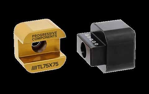
C-12
CATALOG NUMBER T +.00 -.05 W +.00 -.01 A +.00 -.05 B +.00 -.05 C D .002/.008 CLEARANCE PER SIDE R POCKET RADIUS Z SHCS TLM20X20 20 20 14 14 7 9 5 1 M: M4 x 25 F: M4 x 10 TLM25X25 25 25 16 16 8 12 6 1 M: M5 x 25 F: M5 x 10 TLM32X32 32 32 20 20 10 16 7 1 M: M6 x 35 F: M6 x 12 CATALOG NUMBER T +.000 -.002 W +.0000 -.0004 A +.000 -.002 B +.000 -.002 C D 0001/.0003 CLEARANCE PER SIDE R POCKET RADIUS Z SHCS TL75X75 .750 .750 .625 .375 .275 .350 .188 .04 M: #6-32 x 3/4 F: #6-32 x 3/8 TL100X100 1.000 1.000 .875 .500 .450 .500 .250 .04 M: #10-32 x 1 F: #10-32 x 1/2 TL137X137 1.375 1.375 1.125 .625 .550 .750 .375 .04 M: 5/16-18 x 1-3/8 F: 5/16-18 x 3/4 Metric Standard CAD insertion point D B A T W M6 thread for lock removal D C B A R T W Thread for lock removal S1 S2 Z Screws included. Screws
US Patent No. 8,821,144 and others pending.
included.
Female: M D-2 H Core: 58-62 HRC, Surface: 80 HRC S Titanium Nitride Coated
TOP LOCKS Z-SERIES
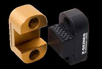
Screws included.
ALTERNATIVE CONFIGURATIONS AVAILABLE
• To order Top Locks with dual radii for mounting internally, specify the catalog number followed by “-R”. Ex.TL112X300-R. As an option, refer to the standard Internal Locks shown on page C-12.
• To order Shuttle Mold sets or special male/female configurations, refer to page C-11.
• Made-to-order Top Locks can be quoted using the templates at procomps.com.
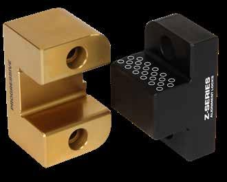
ALIGNMENT LOCKS C-13
CATALOG NUMBER T +.00 -.05 W +.00 -.01 A +.00 -.05 B +.00 -.05 C D .002/.008 CLEARANCE PER SIDE S1 ±.25 S2 ±.25 R POCKET RADIUS Z SHCS TLM26X35 26 35 25 15 17 11 13 23 8 1 M: M5 x 16 F: M5 x 25 TLM30X45 30 45 25 15 17 15 15 30 8 1 M: M6 x 18 F: M6 x 25 TLM36X55 36 55 30 20 21.5 20 18 37.5 8 1 M: M8 x 22 F: M8 x 35 TLM36X75 36 75 35 20 26 30 18 52 8 1.5 M: M10 x 25 F: M10 x 35 TLM45X100 45 100 60 20 42 40 22.5 70 8 1.5 M: M10 x 25 F: M10 x 65 Screws included. CATALOG NUMBER T +.000 -.002 W +.0000 -.0004 A +.000 -.002 B +.000 -.002 C D .0001/.0003 CLEARANCE PER SIDE S1 ±.01 S2 ±.01 R POCKET RADIUS Z SHCS TL50X100 .500 1.000 .500 .375 .30 .375 .25 .68 .188 .03 M: #6-32 x 1/2 F: #6-32 x 5/8 TL62X125 .625 1.250 .625 .500 .41 .438 .31 .87 .250 .03 M: #6-32 x 5/8 F: #6-32 x 3/4 TL75X125 .750 1.250 .625 .500 .38 .438 .37 .87 .250 .04 M: #8-32 x 5/8 F: #8-32 x 3/4 TL87X150 .875 1.500 .875 .750 .57 .500 .43 1.00 .250 .04 M: #8-32 x 7/8 F: #8-32 x 1 TL100X150 1.000 1.500 .875 .375 .57 .500 .50 1.00 .250 .04 M: #10-32 x 1/2 F: #10-32 x 1 TL100X200 1.000 2.000 1.125 .750 .75 .750 .50 1.37 .375 .04 M: #10-32 x 7/8 F: #10-32 x 1-1/8 TL112X200 1.125 2.000 .875 .625 .50 .750 .56 1.37 .375 .04 M: 1/4-20 x 3/4 F: 1/4-20 x 1 TL112X300 1.125 3.000 1.500 .750 .87 1.125 .56 2.25 .500 .04 M: 1/4-20 x 7/8 F: 1/4-20 x 1-5/8 TL150X250 1.500 2.500 1.375 .625 .85 1.000 .75 1.75 .375 .04 M: 1/4-20 x 3/4 F: 1/4-20 x 1-1/2 TL175X300 1.750 3.000 1.250 .875 .75 1.125 .87 2.25 .500 .06 M: 5/16-18 x 1 F: 5/16-18 x 1-1/4 TL200X350 2.000 3.500 1.750 .750 1.07 1.500 1.00 2.50 .500 .06 M: 3/8-16 x 7/8 F: 3/8-16 x 2” R (4) C D S1 R W S2 Z CAD insertion point
US Patent No. 8,821,144 and others pending.
Male:
H Core:
HRC, Surface:
Nitride Inch Standard Metric Standard
M H-13
42-48
70 HRC S Black
ALIGNMENT LOCKS
GUIDE LOCKS Z-SERIES
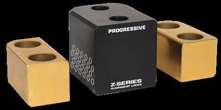
ALTERNATIVE CONFIGURATIONS AVAILABLE
• To order Guide Locks with dual radii for mounting internally, specify the catalog number followed by “-R”. Ex. GL200X350-R.
• Made-to-order Guide Locks can be quoted using the templates at procomps.com.
C-14
CATALOG NUMBER L +.00 -.25 PW +.008 +.015 C +.00 -.01 F +.00 -.12 T +.00 -.01 M H +.0 -.2 S ±.25 R POCKET RADIUS Z SHCS GLM25X45 25 45 15 15 15 10 24 7 4 1 M: M4 x 25 F: M4 x 14 GLM40X65 40 65 20 20 25 15 34 10 9 1.5 M: M5 x 35 F: M5 x 22 GLM50X90 50 90 25 25 40 20 44 10 9 1.5 M: M6 x 45 F: M6 x 30 Metric Standard CATALOG NUMBER L +.000 -.010 PW +.0003 +.0006 C +.0000 -.0003 F +.000 -.005 T +.0000 -.0003 M H +.00 -.01 S ±.01 R POCKET RADIUS Z SHCS GL100X150 1.000 1.500 .500 .500 .500 .375 .85 .25 .187 .03 M: #10-32 x 1 F: #10-32 x 5/8 GL150X250 1.500 2.500 .750 .750 1.000 .625 1.35 .31 .250 .06 M: 1/4-20 x 1-1/2 F: 1/4-20 x 7/8 GL200X350 2.000 3.500 1.000 1.000 1.500 .750 1.73 .44 .375 .06 M: 3/8-16 x 2 F: 3/8-16 x 1-1/4 GL250X450 2.500 4.500 1.250 1.250 2.000 .875 2.11 .56 .500 .09 M: 1/2-13 x 2-1/4 F: 1/2-13 x 1-1/2 R (4) R (2) Each M F PW R C L S S R L S S T H 1/2 C Z Screws included. CAD insertion point Screws included. Inch Standard Females (2): M D-2 H Core: 58-62 HRC, Surface: 80 HRC S Titanium Nitride Coated Male: M H-13 H Core: 42-48 HRC, Surface: 70 HRC S Black Nitride
US Patent No. 8,821,144 and others pending.
RECTANGULAR TAPER BAR LOCKS
Female: M H-13 H Core: 42-48 HRC, Surface: 70 HRC S Black Nitride
Male: M D-2 H Core: 58-62 HRC, Surface: 80 HRC S Titanium Nitride Coated
APPLICATION GUIDELINES
• Lock pockets should be perpendicular to insert side walls to compensate for unequal thermal expansion.
• Mounting pockets must be accurately aligned on the A-side and B-side of the mold.
• Taper Bar Locks should be fit and pre-loaded to assure metal to metal contact on taper geometry.
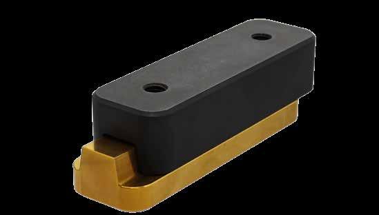
• The back of the Locks can be ground to adjust for pre-load.
ALTERNATIVE CONFIGURATIONS AVAILABLE
• To order Shuttle Mold sets or special male/female configurations, order the quantity of males or female inserts to suit.
ALIGNMENT LOCKS C-15
MALE CATALOG NUMBER FEMALE CATALOG NUMBER L +.000 -.005 W +.0000 -.0004 A +.001 -.000 B +.001 -.000 D1 +.0005 -.0000 D2 +.0000 -.0005 R POCKET RADIUS S ±.01 THD MTBL100 FTBL100 1.99 .999 .690 .312 .5400 .5398 .250 Centered 1/4-20 MTBL125 FTBL125 3.99 1.249 .870 .375 .6700 .6698 .312 2.50 5/16-18 MTBL150 FTBL150 5.99 1.499 1.000 .500 .800 .7998 .375 4.00 3/8-16 MALE CATALOG NUMBER SHCS FEMALE CATALOG NUMBER SHCS MTBL100 #10-24 x 3/4 (1) FTBL100 #10-24 x 1/2 (1) MTBL125 1/4-20 x 7/8 (2) FTBL125 1/4-20 x 5/8 (2) MTBL150 5/16-18x 1 (2) FTBL150 5/16-18 x 3/4 (2) CAD insertion point THD SHCS 10° Female Male R S W L B A D1 D2
included.
Screws
CAVITY INTERLOCKS FLAT
SERIES
Inch Standard
Male: M H-13 H Core: 42-48 HRC, Surface: 70 HRC S Black Nitride
Male: M H-13 H Core: 42-48 HRC, Surface: 70 HRC S Black Nitride
58-62 HRC, Surface: 80 HRC S Titanium Nitride Coated
Female: M DC53 H Core: 58-62 HRC, Surface: 80 HRC S Titanium Nitride Coated Female: M DC53 H
ALTERNATIVE CONFIGURATIONS AVAILABLE
• To order Shuttle Mold sets or special male/female configurations, refer to page C-11.
• Progressive can supply Mold-Ready Flat Cavity Interlocks complete with screw hole locations and lengths modified to suit your application. To order, specify the item code that will be modified from the charts above and provide the following to Customer Service. Note: Minimum order quantity is 2 sets of locks.
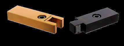
• ML=Male Length (Must be less than “L” above.)
• MS=Male Screw Location (Will be on center.)
• FL=Female Length (Must be less than “L” above.)
• FS=Female Screw Location (Will be on center.)
• Pocket Radius: If required, add “-R” to the specification. (Radius is designed to suit Interlock size.)
Note: Screw size will be the same as within the standards. Any specifications outside of the modifications above can be quoted made-to-order by contacting tech@procomps.com.
ALIGNMENT LOCKS C-16 S1 S2 L C H L W T SHCS D .04” (1mm) Chamfer Metric Standard CATALOG NUMBER T +.000 -.002 W +.0000 -.0002 L +.000 -.002 C D .0001/.00025 CLEARANCE PER SIDE H +.000 -.004 S1 ±.01 S2 ±.01 SHCS CF31X62 .312 .625 1.875 .343 .312 3.750 .68 .68 #8-32 x 3/8” CF50X87 .500 .875 2.875 .530 .438 5.750 1.00 1.00 1/4-20 x 5/8” Screws included. CAD insertion point CATALOG NUMBER T +.00 -.05 W +.000 -.005 L +.00 -.05 C D .003/.006 CLEARANCE PER SIDE H +.0 -.1 S1 ±.25 S2 ±.25 SHCS CFM08X16 8 16 46 8.8 8 92 12.5 20 M4-0.7 X 10 CFM12X20 12 20 66 12.8 12 132 18.5 30 M6-1.0 X 14 Screws
included.
Core:
US Patent No. 8,821,144 and others pending.
SHCS (2) Optional Pocket Radius To Suit (4) ML FL MS FS
CAVITY INTERLOCKS ROUND SERIES
Male: M H-13 H Core: 42-48 HRC, Surface: 70 HRC S Black Nitride
Female: M DC53 H Core: 58-62 HRC, Surface: 80 HRC S Titanium Nitride Coated
Male: M H-13 H Core: 42-48 HRC, Surface: 70 HRC S Black Nitride
Female: M DC53 H Core: 58-62 HRC, Surface: 80 HRC S Titanium Nitride Coated
APPLICATION GUIDELINES
• Interlocks Can be mounted from parting line or bolted from the back of the inserts.
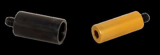
• Vent hole and flat provided on female insert.
• Maximum clearance between female and male insert is .0006” / .015mm total.
• Diameter (DF & DM) Machining Tolerances: Inch: +.0002” / Metric: +.005mm
• Maximum chamfer size should be .02”/.5mm on counterbore.
• The fasteners provided are for parting line installation shown in the graphic above left. For bolting in back, select fasteners to accommodate insert thickness.
• When installing, limit torque specifications according to the chart at right.
ALTERNATIVE CONFIGURATIONS AVAILABLE
• To order Shuttle Mold sets or special male/female configurations, refer to page C-11.
ALIGNMENT LOCKS C-17 DF H Hex T Thread Z Z Z Z DM DF H Hex T S2 Vent Hole Clearance for S1 DM LF LM
Head Cap Screw & Set Screw included. Metric Standard
Head Cap Screw & Set Screw included. CATALOG NUMBER DM -.0001 -.0002 DF +.0000 -.0002 LF +.000 -.002 LM +.000 -.002 PM E Z S1 SHCS SIZE T S2 SET SCREW SIZE H CRS250 .2500 .3750 .687 .812 .500 .23 .03 #6-32 x 3/8 #10-32 #6-32 x 1/2 1/8 CRS375 .3750 .5000 1.000 1.062 .625 .36 .04 #10-32 x 5/8 1/4-20 #10-32 x 5/8 3/16 CRS500 .5000 .6250 1.375 1.375 .750 .51 .04 1/4-20 x 7/8 5/16-18 1/4-20 x 3/4 3/16 CATALOG NUMBER DM -.002 -.006 DF +.000 -.005 LF +.0 -.1 LM +.0 -.1 PM E Z S1 SHCS SIZE T S2 SET SCREW SIZE H CRSM06 6 8 16 18 10 6 .3 M3-0.5 x 8 M4-0.7 M4-0.7 x 12 3 CRSM08 8 12 20 24 14 8 .3 M4-0.7 x 10 M5-0.8 M5-0.8 x 16 4 CRSM10 10 14 22 26 14 10 .3 M4-0.7 x 10 M5-0.8 M6-1.0 x 16 5 CRSM12 12 16 30 32 17 13 .5 M6-1.0 x 16 M8-1.25 M6-1.0 x 16 5 S1 SHCS S2 Set Screw T Thread S2 Thread S1 SHCS S2 Set Screw E PM E PM PL PL PL S1 SHCS S2 Set Screw T Thread S2 Thread S1 SHCS S2 Set Screw E PM E PM PL PL PL Front Mount Back Mount CAD insertion point CATALOG NUMBER TORQUE CRS250 CRSM06 25 IN LB CRS375 75 IN LB CRS500 195 IN LB CRSM08 58 IN LB CRSM10 CRSM12 140 IN LB Inch Standard
Socket
Socket
APPLICATION GUIDELINES
• Designed to be mounted and easily removed from parting line utilzing the internal thread.
• Counterbored Style Taper Locks are sold in sets and the males/ females are designed to be used in assembly and cannot be utilized with the Taper Locks showon page C-19.
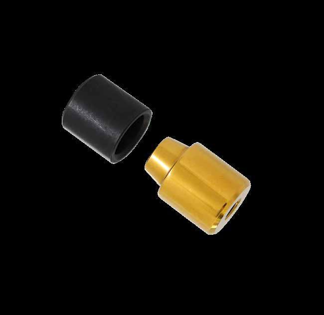
C-18 CATALOG NUMBER O.D. +.0000 -.0003 I.D. M THREAD SIZE L +.004 +.008 SHCS TLC50 .5000 .375 .200 #10-32 .500 M: #6-32 x 3/4 F: #6-32 x 5/16 TLC75 .7500 .500 .250 1/4-20 .750 M:#10-32 x 1-1/8 F: #10-32 x 1/2 TLC100 1.0000 .625 .343 5/16-18 1.000 M: 1/4-20 x 1-1/2 F: 1/4-20 x 3/4 TLC150 1.5000 1.000 .500 3/8-16 1.250 M: 5/16-18x 2 F: 5/16-18x 7/8 TLC200 2.0000 1.500 .500 3/8-16 1.375 M: 5/16-18x 2 F: 5/16-18 x 1 10° Thread for Removal SHCS OD OD ID L L M CAD insertion point Screws included.
Female: M H-13 H Core: 42-48 HRC, Surface: 70 HRC S Black Nitride Male: M DC53 H Core: 58-62 HRC, Surface: 80 HRC S Titanium Nitride Coated
TAPER LOCKS THREADED STYLE
TAPER LOCK PLATES
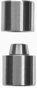
ALIGNMENT LOCKS C-19
T D O.D. +.0000 -.0003 I.D. M THREAD SIZE L +.004 +.008 MALE CATALOG NUMBER FEMALE CATALOG NUMBER .5000 .312 .250 #10-24 .687 MTL50L.68 FTL50L.68 .875 MTL50L.87 FTL50L.87 1.187 MTL50L1.18 FTL50L1.18 1.375 MTL50L1.37 FTL50L1.37 .7500 .500 .281 1/4-20 .687 MTL75L.68 FTL75L.68 .875 MTL75L.87 FTL75L.87 1.187 MTL75L1.18 FTL75L1.18 1.375 MTL75L1.37 FTL75L1.37 1.000 .625 .343 1/4-20 .687 MTL100L.68 FTL100L.68 .875 MTL100L.87 FTL100L.87 1.187 MTL100L1.18 FTL100L1.18 1.375 MTL100L1.37 FTL100L1.37 1.500 1.000 .500 5/16-18 1.125 MTL150L1.12 FTL150L1.12 1.375 MTL150L1.37 FTL150L1.37 1.625 MTL150L1.62 FTL150L1.62 2.000 1.500 .500 5/16-18 1.125 MTL200L1.12 FTL200L1.12 1.375 MTL200L1.37 FTL200L1.37 1.625 MTL200L1.62 FTL200L1.62 10 Female Male OD L Taper Lock Plate (Sold below) M L OD ID FHCS 10° M H-13 H 48-52 HRC CAD insertion point CATALOG NUMBER TAPER LOCK OD D +.000 -.015 T +.000 -.002 FLAT HEAD COUNTERBORE TLP50 1/2 .687 .187 #10-24 TLP75 3/4 1.000 .187 1/4-20 TLP100 1 1.187 .187 1/4-20 TLP150 1-1/2 1.687 .250 5/16-18 TLP200 2 2.187 .250 5/16-18
AISI 52100 H 57-61 HRC S Black Oxide
M
1/2” long FHCS included.
Note: Cages are resin on all Needle Bearing Top Locks.
APPLICATION GUIDELINES
• Needle Bearing Locks have zero clearance between male and female (D) dimensions.
• Bearings are 64 HRC.
• Maximum Mold Temperature: 300°F (150°C)
• Engagement occurs at E dimension shown.
• Locks are to be mounted in the mold base and not in the core or cavity inserts.
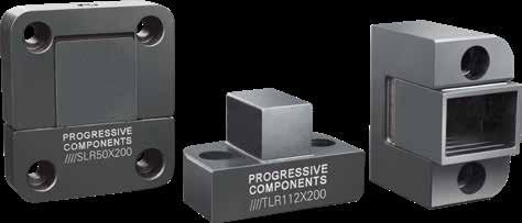
• For optimal performance, pockets are to be machined to nominal “W” pocket width dimensions in each table. If replacing locks in existing pockets, ensure .0004” clearance, and the lock may be modified to suit.
• As with other mold mechanisms, clean and maintain locks at the mold’s scheduled PMs.

C-20 TOP
NEEDLE BEARING B C E D A S1 R T W S2 SHCS (4) 57 ±1 HRC 57 ±1 HRC .02 x 45° Chamfers Screws included. CATALOG NUMBER T + .000 - .005 W +.0004 - .0000 W POCKET WIDTH +.0005 -.0000 A + .000 - .005 B + .000 - .005 C D E S1 ±.01 S2 ±.01 R POCKET RADIUS SHCS TLR87X150 .875 1.4995 1.500 1.375 .750 .66 .550 .225 .43 1.14 .250 M: #8-32 x 7/8 F: #8-32 x 1-1/2 TLR112X200 1.125 1.9995 2.000 1.375 .625 .62 .660 .425 .56 1.37 .375 M: 1/4-20 x 3/4 F: 1/4-20 x 1-1/2 TLR150X250 1.500 2.4995 2.500 1.375 .625 .62 .900 .400 .75 1.75 .375 M: 1/4-20 x 3/4 F: 1/4-20 x 1-1/2 TLR150X250-L 1.500 2.4995 2.500 1.875 .875 1.02 1.015 .350 .75 1.87 .375 M: 1/4-20 x 1 F: 1/4-20 x 2
ALIGNMENT LOCKS
LOCKS
M O-2 H 56-58 HRC S Black Oxide CAD insertion point Inch Standard
SIDE LOCKS NEEDLE BEARING
For application guidelines, refer to page C-20.
Note: Cages are manufactured from resin on all sizes except SLR100X400, which has an aluminum cage.
O-2 H 56-58 HRC S Black Oxide M O-2 H 56-58 HRC S Black Oxide
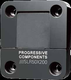
For application guidelines, refer to page C-20.
Note: Cages are manufactured from aluminum on all sizes of metric standard locks.
ALIGNMENT LOCKS C-21
Inch Standard CATALOG NUMBER T + .000 - .005 W ±.0002 W POCKET WIDTH +.0005 -.0000 A + .000 - .005 B + .000 - .005 C D E H + .000 - .004 R POCKET RADIUS S1 ±.01 S2 ±.01 S3 ±.01 S4 ±.01 SHCS SLR50X125 .500 1.2495 1.250 1.375 .875 .66 .412 .210 2.250 .187 .17 .25 .17 .43 #8-32 x 5/8 SLR50X150 .500 1.4995 1.500 .875 .875 .40 .500 .210 1.750 .187 .25 .25 .25 .25 #8-32 x 5/8 SLR50X150-L .500 1.4995 1.500 1.375 .875 .66 .550 .250 2.250 .187 .18 .37 .18 .50 #8-32 x 5/8 SLR50X200 .500 1.9995 2.000 1.375 .875 .66 .750 .325 2.250 .187 .31 .31 .31 .31 #10-32 x 5/8 SLR75X300 .750 2.9995 3.000 1.875 .875 .95 1.188 .575 2.750 .250 .37 .37 .37 .37 1/4-20 x 3/4 SLR100X400 1.000 3.9995 4.000 2.375 1.375 1.34 1.855 .450 3.750 .500 .50 .50 .50 .50 3/8-16 x 1-1/8
M
CATALOG NUMBER T +.00 -.12 W ±.005 W POCKET WIDTH + .012 - .000 A +.00 -.12 B +.00 -.12 C D E H +0.0 -0.1 R POCKET RADIUS S1 ±.25 S2 ±.25 S3 ±.25 SHCS SLRM32X63 32 62.9 63 46 46 27 21 12.1 92 8 9 11 35 M8-1.25 x 35 SLRM40X100 40 99.9 100 66 66 36 33 19.5 132 10 13 18 48 M12-1.75 x 45 D B R H A C S2 S1 SHCS (4) T W S3 S4 .02” (.5mm) Chamfer 57 ±1 HRC 57 ±1 HRC E Screws included. CAD insertion point
Screws included. Metric Standard
ALIGNMENT LOCKS
SIDE LOCK DIE CAST SERIES
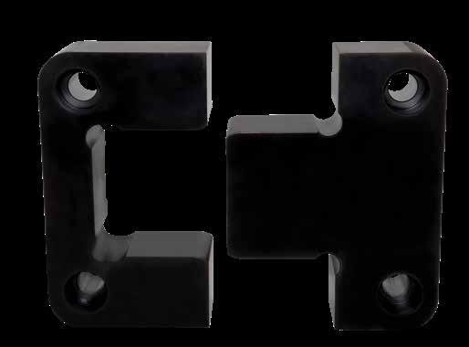
C-22
Screws included. CATALOG NUMBER T + .000 - .002 W +.0000 -.0004 A + .000 - .002 B + .000 - .002 C D .0004/.001 CLEARANCE PER SIDE H + .000 - .004 R POCKET RADIUS S1/S2/S3 ±.01 Z SHCS SL200X650-BN 2.000 6.500 3.750 2.374 2.62 3.000 6.125 .750 .87 .12 5/8-11 x 2-1/4 CAD insertion point T Z H C D R W S3 SHCS B A S2 S1 M H-13 H Core: 42-48 HRC, Surface: 66-70 HRC S Black Nitride
SIDE LOCKS
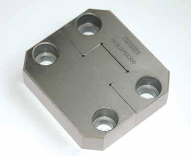
ALIGNMENT LOCKS C-23
50-55 HRC B X A S2 S1 H C SHCS S3 T W D 55-60 HRC Z CATALOG NUMBER T +.000 -.002 W +.0000 -.0004 A +.0000 -.0008 B +.0000 -.0008 C D 0001/.0003 CLEARANCE PER SIDE H + .000 - .002 X CORNER CHAMFER Z CHAMFER S1 ±.01 S2 ±.01 S3 ±.01 SHCS SLS62X150 .620 1.500 .870 .870 .33 .500 1.74 .19 .02 .43 .28 .28 1/4-20 x 3/4 SLS62X200 .620 2.000 .870 .870 .33 .680 1.74 .19 .04 .43 .37 .37 1/4-20 x 3/4 SLS75X300 .745 3.000 1.370 1.360 .57 1.000 2.73 .38 .04 .68 .68 .37 3/8-16 x 1 SLS75X400 .745 4.000 1.870 1.870 .79 1.375 3.74 .50 .04 .87 .87 .62 3/8-16 x 1 SLS112X500 1.120 5.000 1.870 1.870 .79 1.750 3.74 .50 .04 .87 .87 .75 1/2-13 x 1-1/4 Screws included. CATALOG NUMBER T +.00 -.05 W +.00 -.01 A +.00 -.02 B +.00 -.02 C D 002/.008 CLEARANCE PER SIDE H + .00 - .04 X CORNER CHAMFER Z CHAMFER S1/S2 ±.25 S3 ±.25 SHCS SLMS13X38 13 38 22 22 8.5 12 44 5 .5 7 8 M5-.8 x 15 SLMS16X50 16 50 21.5 21.5 9.5 17 43 5 1 11 8 M6-1.0 x 18 SLMS19X75 19 75 36 36 15 25 72 8 1 18 12.5 M10-1.5 x 20 SLMS19X100 19 100 45 45 21 35 90 10 1 22 15 M10-1.5 x 20 SLMS25X125 25 125 45 45 21 45 90 10 1 22 20.5 M10-1.5 x 25 Screws included. CAD insertion point M O-2 H 55-60 HRC Metric Standard Inch Standard
SIDE LOCKS
APPLICATION GUIDELINES
• Using grease will inhibit the function of the graphite plugs. Instead, use a light 20 weight oil at startup to begin lubrication.
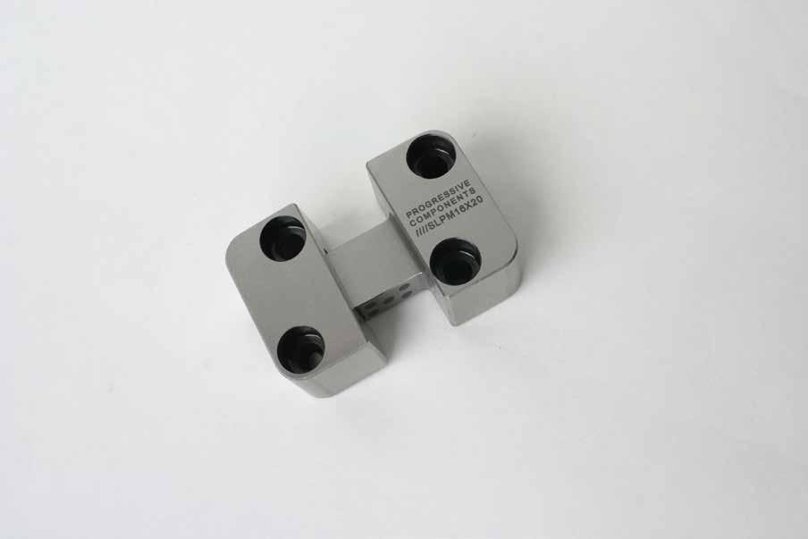
C-24
H H L S1 D T T S W C .5mm -.5 -.7 g4 g5 -.5 -.7 +.0 -.1 +.0 -.1 R S2 S2 S1 Z CATALOG NUMBER L D T W C H S1 S2 S R Z SHCS SLPM16X20 20 16 20 40 11 22 7 15 26 6 1 M6-1.0 x 25 SLPM16X40 40 SLPM20X25 25 20 22 45 13 27 7 19 31 6 1 M6-1.0 x 25 SLPM20X50 50 SLPM25X32 32 25 25 50 14 36 9 27 35 8 1 M6-1.0 x 30 SLPM25X63 63 SLPM32X40 40 32 32 63 19 46 11 35 45 8 1 M8-1.25 x 35 SLPM32X80 80 SLPM40X50 50 40 36 85 22 56 15 40 60 10 1.5 M10-1.5 x 40 SLPM40X100 100 SLPM50X56 56 50 40 100 24 66 18 48 74 10 1.5 M12-1.75 x 45 SLPM50X112 112 Screws included. M O-2 H 56-60 HRC CAD insertion point Metric Standard
GRAPHITE PLUGGED
DATE MARKING, AIR VALVES SECTION D
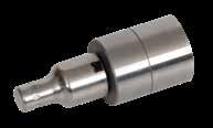
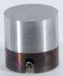

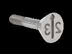

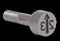

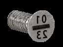
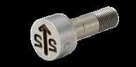
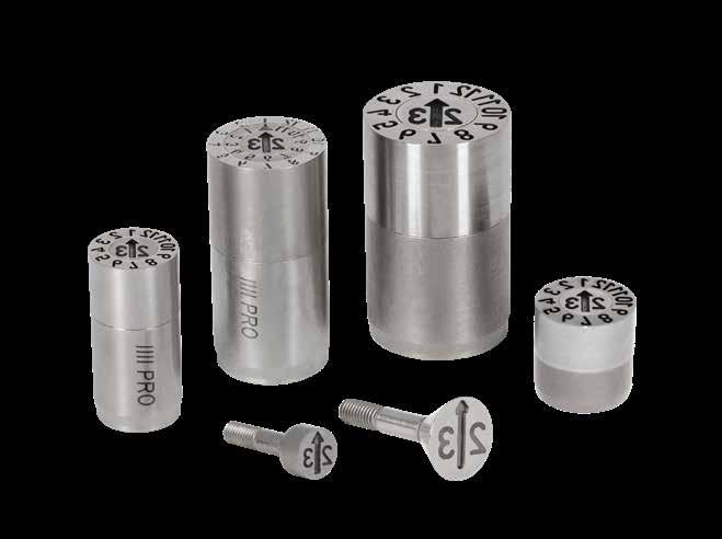
Locking Series Tapered Series RF Series 20 Series Prefix: DN, DTN Prefix: DTPR Prefix: DF Prefix: DL Pages: D-1 Page: D-3 Page: D-4 Page: D-5 D Series CH Series FD Series Multi-Daters Prefix: DC, Suffix: -D Prefix: DC Prefix: DFD Prefix: DMD Page: D-5 Page: D-6 Page: D-7 Page: D-8 Replacement Plugs MicroDaters LG Series Recycle Inserts Prefix: DP, DXP Prefix: MD Prefix: DLB, DLS Prefix: RI Page: D-9 Page: D-10 Page: D-11 Page: D-12 Air Valves Air Poppets Prefix: AV Prefix: APV Page: D-13 Page: D-14
DATE STAMPS LOCKING DETENT SERIES
9 78 45 3 21 1111 0 2
RINGS PLUGS
M 420 Stainless (1.4034) H 54-58 HRC
Hex is present for tightening the set screw thread from parting line when plug is not installed.
CAD insertion point
Ex.: DNP05-AO
C Cat #: DNP-Diam-C
Ex.: DNP05-C
APPLICATION GUIDELINES
• Ring can be installed using the included set screw or retained with a screw from the back.
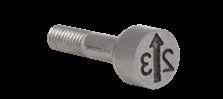
• Maximum mold temperature:
Ø4mm: 662°F (350°C)
Ø5-Ø16mm: 932°F (500°C)
• Where years are specified (*), any year can be ordered by changing the suffix. Example: DNP05-24 or DNY05-25.
• To create Date Stamps for days, purchase both the 0-30 ring (DNT) and the 0-9 ring (DNN) and the desired plugs.
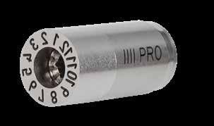
• Special configurations are available. Contact Customer Service for more information.
#:
8232 2726 25 42 Years
#: DNY-Diam-Starting Year*
DATE MARKING, AIR VALVES D-1
Patent No. DE 4415583 A Etched for replacement source PROCOMPS.COM P M D H7 Date Plug (Optional SHCS) (Set Screw) Date Ring No height variation during rotation M (Max) T D T T L 56 ± 2 HRC M h6 +.05 -.00 LP
9 9 78 45 3 21 1111 0 2 L CATALOG NUMBER C A LP P ENGRAVING DEPTH (ARROW) DNP04-23 2.5 2.3 10.5 M1.4 x 0.2 .30 DNP05-23 3.1 2.8 13.0 M1.6 x 0.2 .40 DNP06-23 3.1 2.8 13.0 M1.6 x 0.2 .40 DNP08-23 4.6 4.0 14.0 M2.5 x 0.35 .40 DNP10-23 4.6 4.0 14.0 M2.5 x 0.35 .40 DNP12-23 6.4 4.0 17.0 M3 x 0.5 .60 DNP16-23 8.4 5.0 23.0 M3.5 x 0.6 .60 C A Etched for replacement source PROCOMPS.COM 2 3 P M D H7 Date Plug (Optional SHCS) (Set Screw) Date Ring No height variation during rotation M (Max) T D T T L 56 ± 2 HRC M h6 +.05 -.00 LP
L CATALOG NUMBER D L M T ENGRAVING DEPTH DN04 4 14 M2 x 0.4 3 .10 DN05 5 17 M3 x 0.5 3 .20 DN06 6 17 M3 x 0.5 3 .20 DN08 8 20 M4 x 0.7 4 .20 DN10 10 20 M5 x 0.8 4 .20 DN12 12 25 M6 x 1.0 6 .25 DN16 16 33 M8 x 1.25 8 .25 Plug Styles: Recessed Lettering Ring Styles: Recessed Lettering 0 1 2 3 4 5 6 7 8 9 0 - 9 A G HI J LK CB D EF A - L Cat #: DNN-Diam Cat #: DNA-Diam Ex.: DNN05 Ex.: DNA05 0 20 10 30 0 - 30 M STUV XW ON PQR M - X Cat #: DNT-Diam Cat #: DNZ-Diam Ex.: DNT05 Ex.: DNZ05 Blank
Cat
Hex is present for tightening the set screw thread from parting line when plug is not installed. DN-Diam-B Cat
9 Ex.: DN05-B Ex.: DNY05-23
Arrow Only
Cat #: DNP-Diam-AO
To Order:
• Specify catalog number as shown above and below for the different style plugs and rings.
DATE STAMPS COMPACT LOCKING DETENT SERIES
RINGS
Arrow Only
Cat #: DTNP-Diam-AO
Ex.: DTNP05-AO
C Cat #: DTNP-Diam-C
Ex.: DTNP05-C
To Order:
• Specify catalog number as shown above and below for the different style plugs and rings.
• Where years are specified (*), any year can be ordered by changing the suffix. Example: DTNP05-24 or DTNY05-25.
• To create Date Stamps for days, purchase both the 0-30 ring (DNT) and the 0-9 ring (DNN) and the desired plugs.
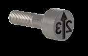
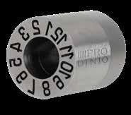
• Special configurations are available. Contact Customer Service for more information.
Ring Styles: Recessed
Blank 8232 2726 25 42 Years
Cat #: DTN-Diam-B Cat #: DTNY-Diam-Starting Year* Ex.: DTN05-B Ex.: DTNY05-23
APPLICATION GUIDELINES
• Maximum molding pressure: 20,000 psi/2,000 bar.
• Maximum mold temperature: Ø3-Ø4mm: 662°F (350°C) / Ø5-Ø20mm: 932°F (500°C)
D-2
DATE MARKING, AIR VALVES
CATALOG NUMBER C A LP P ENGRAVING DEPTH (ARROW) DTNP03-23 1.6 1.0 3.8 M1 x 0.25 .20 DTNP04-23 2.5 1.2 4.8 M1.4 x 0.2 .30 DTNP05-23 3.1 2.0 7.8 M1.6 x 0.2 .40 DTNP06-23 3.1 2.0 7.8 M1.6 x 0.2 .40 DTNP08-23 4.4 2.5 9.8 M2.3 x 0.25 .40 DTNP10-23 5.2 3.0 11.8 M2.5 x 0.35 .40 DTNP12-23 6.2 3.0 13.8 M3 x 0.35 .60 DTNP16-23 8.2 3.5 13.8 M4 x 0.35 .60 DTNP20-23 11.0 4.5 15.8 M4 x 0.35 .60 A Etched for replacement source P No height variation during rotation D L 56 ± 2 HRC m6 +.05 -.00 LP 9 9 78 45 3 21 1111 0 2 //// Clearance to drive out assembly if required. D B H7 Date Plug Date Ring L ±.02 PRO C A Etched for replacement source 2 3 P No height variation during rotation D L 56 ± 2 HRC m6 +.05 -.00 LP 9 9 78 45 3 21 1111 0 2 //// Clearance to drive out assembly if required. D B H7 Date Plug Date Ring L ±.02 PRO CATALOG NUMBER D L B MAX FROM GRAPHIC BELOW ENGRAVING DEPTH DTN03 3 4 1.6 .10 DTN04 4 5 2.2 .15 DTN05 5 8 3.2 .20 DTN06 6 8 3.2 .20 DTN08 8 10 4.2 .20 DTN10 10 12 5.2 .20 DTN12 12 14 6.2 .25 DTN16 16 14 8.2 .25 DTN20 20 16 10.2 .30
Lettering
Lettering 0 1 2 3 4 5 6 7 8 9 0 - 9 A G HI J LK CB D EF A - L Cat #: DTNN-Diam Cat #: DTNA-Diam Ex.: DTNN05 Ex.: DTNA05 0 20 10 30 0 - 30 M STUV XW ON PQR M - X Cat #: DTNT-Diam Cat #: DTNZ-Diam Ex.: DTNT05 Ex.: DTNZ05
Plug Styles: Recessed
H 54-58
Patent No. DE 4415583
CAD insertion point M 420 Stainless (1.4034)
HRC
PLUGS
Tapered seal for Nylon, LSR, etc.
PLUGS
RINGS
To Order:
• Specify catalog number as shown above and below for the different style plugs and rings.
• Where years are specified (*), any year can be ordered by changing the suffix. Example: DTPRP05-24 or DTPRY05-25.
• To create Date Stamps for days, purchase both the 0-30 ring (DTPRT) and the 0-9 ring (DTPRN) and the desired plugs.
• Special configurations are available. Contact Customer Service for more information.
Plug Styles: Recessed Lettering
Arrow Only Cat #: DTPRP-Diam-AO Ex.: DTPRP05-AO
C Cat #: DTPRP-Diam-C Ex.: DTPRP05-C
APPLICATION GUIDELINES
• Ring can be installed using the included set screw or retained with a screw from the back.
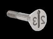
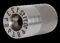
• Maximum mold temperature:
Ø4mm: 662°F (350°C)
Ø5-Ø20mm: 932°F (500°C)
Blank 8232 2726 25 42 Years
Cat #: DTPRY-Diam-Starting Year* Ex.: DTPR05-B Ex.: DTPRY05-23
DATE MARKING, AIR VALVES D-3
TAPERED
A Etched for replacement source PROCOMPS.COM D T T L 56 ± 2 HRC M h6 +.05 -.00 LP Hex
line
plug is not installed. 9 9 78 45 3 21 1111 0 2 M D H7 Date Plug (Optional SHCS) (Set Screw) Date Ring No height variation during rotation L M (Max) T Tapered seal for Nylon, LSR, etc. C A Etched for replacement source PROCOMPS.COM 2 3 P D T T L 56 ± 2 HRC M h6 +.05 -.00 LP Hex
plug is not installed. 9 9 78
3 21 1111
2 M D H7 Date Plug (Optional SHCS) (Set Screw) Date Ring No height variation during rotation L M (Max) T
DATE STAMPS
SERIES
is present for tightening the set screw thread from parting
when
is present for tightening the set screw thread from parting line when
45
0
CATALOG NUMBER C A LP P ENGRAVING DEPTH (ARROW) DTPRP04-23 2.5 2.3 10.5 M1.4 x 0.2 .30 DTPRP05-23 3.1 2.8 13.0 M1.6 x 0.2 .40 DTPRP06-23 3.1 2.8 13.0 M1.6 x 0.2 .40 DTPRP08-23 4.6 4.0 14.0 M2.5 x 0.35 .60 DTPRP10-23 4.6 4.0 14.0 M2.5 x 0.35 .60 DTPRP12-23 6.4 4.0 17.0 M3 x 0.5 .60 DTPRP16-23 8.4 5.0 23.0 M3.5 x 0.6 .60 DTPRP20-23 11 6.5 23.0 M3.5 x 0.6 .60 CATALOG NUMBER D L M T ENGRAVING DEPTH DTPR04 4 14 M2 x 0.4 3 .15 DTPR05 5 17 M3 x 0.5 3 .20 DTPR06 6 17 M3 x 0.5 3 .20 DTPR08 8 20 M4 x 0.7 4 .30 DTPR10 10 20 M5 x 0.8 4 .30 DTPR12 12 25 M6 x 1.0 6 .30 DTPR16 16 33 M8 x 1.25 8 .30 DTPR20 20 33 M8 x 1.25 8 .30 Ring Styles: Recessed
Lettering
0 1 2 3 4 5 6 7 8 9 0 - 9 CBA D EFGHIJ K ML A - M Cat #: DTPRN-Diam Cat #: DTPRA-Diam Ex.: DTPRN05 Ex.: DTPRA05 0 20 10 30 0 - 30 QPON RSTUVW ZYX N - Z Cat #: DTPRT-Diam Cat #: DTPRZ-Diam Ex.: DTPRT05 Ex.: DTPRZ05
DTPR-Diam-B
Cat #:
CAD insertion point
Patent No. DE 4415583
M 420 Stainless (1.4034) H 54-58 HRC
DATE STAMPS
PLUGS
M 420 Stainless (1.4034) H 54-58 HRC
CAD insertion point
RINGS
† 3mm size not available with raised lettering. Raised Lettering Height is equal to L1 minus L2 on each available diameter.
To Order:
• Specify catalog number as shown above and below for the different style plugs and rings.
• Where years are specified (*), any year can be ordered by changing the suffix. Example: DFP05-24 or DFY05-25.
• Special configurations are available. Contact Customer Service for more information.
Plug Styles: Recessed Lettering
Arrow Only Cat #: DFP-Diam-AO
Ex.: DFP05-AO
C Cat #: DFP-Diam-C Ex.: DFP05-C
Plug Styles: Raised Lettering
23 Year Cat #: DFRP-Diam-Year* Ex.: DFRP05-23
Arrow Only Cat #: DFRP-Diam-AO
Ex.: DFRP05-AO
C Cat #: DFRP-Diam-C Ex.: DFRP05-C
APPLICATION GUIDELINES
• Ring can be installed using the included set screw or retained with a screw from the back.
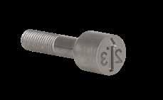
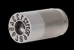
• Maximum mold temperature:
Ø4mm: 662°F (350°C)
Ø5-Ø16mm: 932°F (500°C)
Year*
DATE MARKING,
D-4
AIR VALVES
RF SERIES: REMAINS FLUSH
C A Etched for replacement source L2 PROCOMPS.COM 1 8 P C A Etched for replacement source RF ONLY LP PROCOMPS.COM P C A Etched for replacement source L2 PROCOMPS.COM P 1 8 2 3 M D H7 D H7 Min Date Plug (Optional SHCS) (Set Screw) Date Ring No height variation during rotation L2 L1 D T1 M L1 56 ± 2 HRC Hex is present for tightening the set screw thread from parting line when plug is not installed. M (Max) 9 9 78 45 3 21 1111 0 2 h6 + 0.1 - 0.0 L2 ±.05 Raised Lettering Height T2 L2 ±.05 Raised Lettering Height RECESSED CATALOG NUMBER C A LP P RECESSED ENGRAVING DEPTH ENGRAVING DEPTH (ARROW) RAISED SLOT DEPTH DFP03-23 1.6 2.0 9.0 M1 x 0.25 0.10 .30 N/A† DFP04-23 2.5 2.3 10.5 M1.4 x 0.2 0.10 .30 .25 DFP05-23 3.1 2.8 13.0 M1.6 x 0.2 0.15 .40 .30 DFP06-23 3.1 2.8 13.0 M1.6 x 0.2 0.15 .40 .30 DFP08-23 4.6 4.0 14.0 M2.5 x 0.35 0.20 .40 .35 DFP10-23 4.6 4.0 14.0 M2.5 x 0.35 0.20 .40 .35 DFP12-23 6.4 4.0 17.0 M3 x 0.5 0.25 .60 .40 DFP16-23 8.4 5.0 23.0 M3.5 x 0.6 0.25 .60 .40 RECESSED CATALOG NUMBER D L1 RECESSED L2 RAISED M T1 T2 DF03 3 14 N/A† M2 x 0.4 4 3† DF04 4 14 13.80 M2 x 0.4 4 3 DF05 5 17 16.75 M3 x 0.5 4 3 DF06 6 17 16.75 M3 x 0.5 4 3 DF08 8 20 19.70 M4 x 0.7 4 4 DF10 10 20 19.70 M5 x 0.8 4 4 DF12 12 25 24.70 M6 x 1.0 6 6 DF16 16 33 32.70 M8 x 1.25 8 8 Ring Styles: Recessed Lettering 0 1 2 3 4 5 6 7 8 9 0 - 9 Blank Cat #: DFN-Diam Cat #:DF-Diam-B Ex.: DFN05 Ex.: DF05-B CBA D EFGHIJ K ML A - M Days Cat #: DFA-Diam Cat #:DFL-Diam Ex.: DFA05 Ex.: DFL05 QPON RSTUVW ZYX N - Z 8232 2726 25 42 Years Cat #: DFZ-Diam Cat #: DFY-Diam-Starting Year* Ex.: DFZ05 Ex.: DFY05-23
Styles: Raised Lettering 0 1 2 3 4 5 6 7 8 9 0 - 9 Days Cat #: DFRN-Diam Cat #: DFRL-Diam Ex.: DFRN05 Ex.: DFRL05 CBA D EFGHIJ K ML A-M Months Cat #: DFRA-Diam Cat #: DFR-Diam Ex.: DFRA05 Ex.: DFR05 QPON RSTUVW ZYX N-Z 8232 2726
42
Cat #: DFRZ-Diam Cat #: DFRY-Diam-Starting
Ex.: DFRZ05 Ex.: DFRY05-23
Ring
25
Years
Patent No. DE 4415583
M D H7 D H7 Min Date Plug (Optional SHCS) (Set Screw) Date Ring No height variation during rotation L2 L1 D T1 M L1 56 ± 2 HRC Hex
M (Max) 9 9 78 45 3 21 1111 0 2 h6 + 0.1 - 0.0 T2
is present
for tightening the set screw thread from parting line when plug is not installed.
DATE STAMPS
20 SERIES: 20MM LENGTH
APPLICATION GUIDELINES
• Maximum mold temperature: 285˚F (140˚C)
To Order:
• For other date plugs, modify catalog number for the year required. Example: DLP06-24.
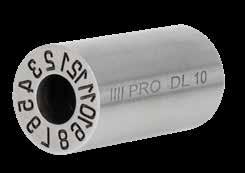
• Plugs include springs and replacements are available.
• Special configurations are available. Contact Customer Service for more information.
D SERIES: DEEP ENGRAVING
To Order:
• For other date plugs, modify catalog number for the year required. Example: DCP16D-24.
• Plugs include springs and replacements are available.
• Special configurations are available. Contact Customer Service for more information.
APPLICATION GUIDELINES
• Maximum mold temperature: 285˚F (140˚C)
DATE MARKING, AIR VALVES D-5
CATALOG NUMBER D M L DL06 6 M3x0.5 20 DL08 8 M4x0.7 DL10 10 M5x0.8 DL16 16 M8x1.25 CATALOG NUMBER C A L2 P ARROW ONLY DLP06-23 3.1 3.0 13 M1.6x0.20 DLP06-AO DLP08-23 4.6 4.0 14 M2.5x0.35 DLP08-AO DLP10-23 4.6 4.0 14 M2.5x0.35 DLP10-AO DLP16-23 8.2 3.5 14 M4x0.35 DLP16-AO D L
D H7 D - 2mm (Max) Date Plug Spring Date Ring Height variation during rotation .2-.3mm L Clearance to drive out assembly if required. D B H7 Date Plug Spring Date Ring Cooling Line Height variation during rotation .2-.3mm L 52 ±2 HRC Clearance to drive out assembly if required. Jack Thread D H7 (SHCS) M ±.02 ±.02 C A L2 P Etched for replacement source 2 3 //// PR O Engraving Depth: Numbers: 5mm (.020”) Arrows: .4mm (.015”) CATALOG NUMBER C A L2 P ARROW ONLY DCP10D-23 5.2 3.0 12 M2.5x0.35 DCP10-AO DCP12D-23 6.2 3.0 14 M3x0.35 DCP12-AO DCP16D-23 8.2 3.5 14 M4x0.35 DCP16-AO DCP20D-23 11.0 4.5 16 M4x0.35 DCP20-AO CATALOG NUMBER D L DC10-D 10 12 DC12-D 12 14 DC16-D 16 14 DC20-D 20 16 C A L2 P Etched for replacement source 2 3 //// PR O Engraving Depth: Numbers: 2mm (.007”) Arrows: .4mm (.015”) D L A Socket Head
stamp. (Optional) Clearance to drive out assembly if required. D H7 or +.0004" - .0000" D - 2mm (max) Date Plug Spring Date Ring L 52 ±2 HRC m6 M L D D +.0004 - 0000 L ±.001 52 ±2 HRC m6 RINGS PLUGS RINGS PLUGS CAD insertion point M 420 Stainless (1.4034) H 50-54 HRC CAD insertion point M 420 Stainless (1.4034) H 50-54 HRC
A
Socket Head Cap Screw may be installed to secure the date stamp.
(Optional)
Cap Screw may be installed to secure the date
DATE STAMPS
To Order:
• Specify catalog number as shown above and below for the different style plugs and rings.
• Where years are specified (*), any year can be ordered by changing the suffix. Example: DCP05-24 or DCY05-25.
• Use both the Weeks Ring (DCW) and 0-9 Ring (DCN) to designate specific weeks of the year.
• Plugs include springs and replacements are available.
• Special configurations are available. Contact Customer Service for more information.
Plug Styles: Recessed Lettering
Arrow Only Cat #: DCP-Diam-AO
Ex.: DCP05-AO
C Cat #: DCP-Diam-C
Ex.: DCP05-C
APPLICATION GUIDELINES
• Maximum mold temperature: 285˚F (140˚C)
Ring Styles: Recessed Lettering
D-6
DATE MARKING, AIR VALVES
CH SERIES: COMPACT HEIGHT D L D H7 D - 2mm (Max) Date Plug Spring Date Ring Height variation during rotation .2-.3mm L Clearance to drive out assembly if required. D B H7 Date Plug Spring Date Ring Cooling Line Height variation during rotation .2-.3mm L 52 ±2 HRC Clearance to drive out assembly if required. Jack Thread D H7 (SHCS) M ±.02 ±.02 C P A L2 //// Etched for replacement source 2 3 PR O Engraving Depth: Numbers: 2mm (.007”) Arrows: 4mm (.015”) L D D +.0004 - 0000 L ±.001 m6 CATALOG NUMBER C A L2 P DCP04-23 2.2 2.0 8 M1x0.25 DCP05-23 3.1 2.0 8 M1.6x0.20 DCP06-23 3.1 2.0 8 M1.6x0.20 DCP08-23 4.4 2.5 10 M2.3x0.25 DCP10-23 5.2 3.0 12 M2.5x0.35 DCP12-23 6.2 3.0 14 M3x0.35 DCP16-23 8.2 3.5 14 M4x0.35 DCP20-23 11.0 4.5 16 M4x0.35 CATALOG NUMBER D L BELOW DC04 4 8 1.4 DC05 5 8 2 DC06 6 8 2 DC08 8 10 3 DC10 10 12 3 DC12 12 14 4 DC16 16 14 5 DC20 20 16 5 CAD insertion point M 420 Stainless (1.4034) H 54-58 HRC PLUGS 0 1 2 3 4 5 6 7 8 9 0 - 9 CBA D EFGHIJ K ML A - M Cat #: DCN-Diam Cat #: DCA-Diam Ex.: DCN05 Ex.: DCA05 Blank QPON RSTUVW ZYX N - Z Cat #: DC-Diam-B Cat #: DCZ-Diam Ex.: DC05-B Ex.: DCZ05 Days 8232 2726 25 42 Years Cat #: DCL-Diam Cat #: DCY-Diam-Starting Year* Ex.: DCL05 Ex.: DCY05-23
The DCL04 and DCL05 does not have tick marks. 3 1 2 4 Quarters 2 0 1 3 Shifts Cat #: DCQ-Diam Cat #: DCS-Diam Ex.: DCQ05 Ex.: DCS05 0 30 50 20 40 10 Weeks Cat #: DCW-Diam Ex.: DCW05
Note:
PLUGS
DATE STAMPS
APPLICATION GUIDELINES
• Maximum mold temperature: 285˚F (140˚C)
To Order:
• Specify catalog number as shown above for the different style plugs or shells.
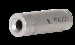
• Where years are specified (*), any year can be ordered by changing the suffix. Example: DFDPY03-24 or DFDPY03-25.
• Special configurations are available. Contact Customer Service for more information.
DATE MARKING, AIR VALVES D-7
DIAMETER
PROCOMPS.COM L T K B A L2 D D M Shell Plug EDM Arrow Detail L D M P No height variation during rotation 56 ±2 HRC g6 m6 Etched for replacement source H7 3 2 Month & Year* Cat #: DFDPY-Diam–Starting Year* Ex.: DFDPY03-23 L T D Shell Plug M No height variation during rotation m6 3 2 Months Cat #: DFDP-Diam Ex.: DFDP03 PROCOMPS.COM L T A L2 D D M Shell Plug EDM Arrow Detail L D M P No height variation during rotation 56 ±2 HRC g6 m6 Etched for replacement source H7 3 2 PROCOMPS.COM L T K B D D M Shell Plug EDM Arrow Detail L D M P No height variation during rotation 56 ±2 HRC g6 m6 Etched for replacement source H7 3 2 CATALOG NUMBER A B K L2 P DFDPY03-23 .3 .3 2.0 9.0 M1x0.25 DFDPY04-23 .3 .3 2.3 10.5 M1.4x0.2 CATALOG NUMBER D T L M DFD03-S 3 3 14 M2 x 0.4 DFD04-S 4 3 14 M2 x 0.4
CAD insertion point M 420 Stainless (1.4034) H 54-58 HRC
FD SERIES: FULL
PLUG
SHELL
DATE MARKING, AIR VALVES
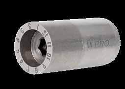
DATE STAMPS
RINGS PLUGS
Years & Months plug style is featured in the table above
To Order:
• Specify catalog number as shown above or below for the different style plugs or rings.
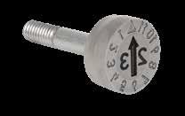
• Where years are specified (*), any year can be ordered by changing the suffix. Example: DMDP10-24 or DMDP06-25.
• Special configurations are available. Contact Customer Service for more information.
APPLICATION GUIDELINES
• Maximum mold temperature: 450°F (230°C)
Plug Styles: Recessed Lettering
Arrow & 6 Years
Cat #: DMDP-Diam-Starting Year*-5
Ex.: DMDP06-235
Arrow & 11 Years
Cat #: DMDP-Diam-Starting Year*-11
Ex.: DMDP06-2311
Ring Styles: Recessed Lettering
Days
Cat #: DMDL-Diam
Ex.: DMDL06
Weeks
Cat #: DMDW-Diam
Ex.: DMDW06
D-8
MULTI-DATERS D T L 56 ±2 HRC C Etched for replacement source Hex for removal 23 24 25 26 28 27 3 2 23 25 27 29 32 33 23 24 25 26 28 27 M D H7 Date Plug Date Ring L1 PROCOMPS.COM M P h6 ±.05 M D H7 No height variation during rotation L2 (Set Screw) (SHCS) C Etched for replacement source Hex for removal 23 24 25 26 28 27 M D H7 Date Plug Date Ring L1 PROCOMPS.COM P M D H7 No height variation during rotation L2 (Set Screw) (SHCS) Patent No. DE 4415583 D T L 56 ±2 HRC C Etched for replacement source Hex for removal 23 24 25 26 28 27 3 2 23 25 27 29 32 33 23 24 25 26 28 27 M D H7 Date Plug Date Ring L1 PROCOMPS.COM M P h6 ±.05 M D H7 No height variation during rotation L2 (Set Screw) (SHCS) T L 56 ±2 HRC 3 2 23 25 27 29 32 33 23 24 25 26 28 27 M ±.05 CATALOG NUMBER C SLOT DEPTH P ENGRAVING DEPTH (ARROW) DMDP06-23 4.2 0.4 M1.6x0.2 0.10 DMDP08-23 5.8 0.4 M2.5x0.35 0.10 DMDP10-23 7.0 0.4 M2.5x0.35 0.10 DMDP12-23 8.5 0.6 M3.0x0.5 0.20 DMDP16-23 11.5 0.6 M3.0x0.6 0.25 CATALOG NUMBER D L M T ENGRAVING DEPTH DMD06 6 17 M3 x 0.5 3 0.10 DMD08 8 20 M4 x 0.7 4 0.12 DMD10 10 20 M5 x 0.8 4 0.13 DMD12 12 25 M6 x 1.0 6 0.20 DMD16 16 33 M8 x 1.25 8 0.25
T 56 ±2 HRC 3 2 23 25 27 29 32 33 23 24 25 26 28 27 M
T 56 ±2 HRC 3 2 23 25 27 29 32 33 23 24 25 26 28 27 M
Months ring style is featured in the table above
CAD insertion point
M 420 Stainless (1.4034) H 54-58 HRC
Refer to the catalog pages for the specific series required for plugs with alternate engraving such as “C”, “Arrow Only”, or raised versions. Contact Customer Service for availability of special plugs or for verification of the plugs required in your application.
TAPERED SERIES
DATE STAMPS REPLACEMENT PLUGS
COMPACT LOCKING
RF SERIES
To replace Progressive’s Locking Series plugs
To replace Progressive’s Tapered Series plugs
To replace Progressive’s Compact Locking Series plugs
To replace Progressive’s RF or H Series plugs.
To replace Progressive’s CH, D, or 20 Series plugs or DME front style plugs. Springs included.
To replace Progressive’s Multi-Dater Plugs.
To replace plugs previously purchased for PCS®/ Cumsa® style rings.
To replace plugs previously purchased for DME® Indexable style rings.
For Retro Plugs outside of North America, call for availability from local distributors.
For D Series replacements, add “D” to the CH Series catalog number. Ex. DCP16D-23.
DATE MARKING, AIR VALVES D-9
CATALOG NUMBER DATE RING CATALOG NUMBER C DP22-23 DS04 2.2 DP30-23 DS05 3.0 DP32-23 DS06 3.2 DP47-23 DS08 4.7 DP57-23 DS10 5.7 DP67-23 DS12 6.7 DP87-23 DS16 8.7 CATALOG NUMBER DATE RING DME NUMBER C DXP04-23 UUM0004 2.4 DXP06-23 UUM0006 3.7 DXP08-23 UUM0008 5.0 DXP10-23 UUM0010 6.3 DXP12-23 UUM0012 7.5 DXP16-23 UUM0016 11.0 DXP20-23 UUM0020 13.2
LOCKING SERIES CH, D, & 20 SERIES MULTI-DATERS RETRO PLUGS INDEXABLE PLUGS C C C C C PROCOMPS.COM C PROCOMPS.COM C PROCOMPS.COM C PROCOMPS.COM C //// PR O C ////PRO C C C PROCOMPS.CO M ////PRO DP22/30: 7.7mm (.30”) All others: 17mm (.67”)
CATALOG NUMBER DATE RING CATALOG NUMBER C DNP04-23 DN04 2.5 DNP05-23 DN05 3.1 DNP06-23 DN06 3.1 DNP08-23 DN08 4.6 DNP10-23 DN10 4.6 DNP12-23 DN12 6.4 DNP16-23 DN16 8.4
CATALOG NUMBER DATE RING CATALOG NUMBER C DCP04-23 DC04 2.2 DCP05-23 DC05 3.1 DCP06-23 DC06 3.1 DCP08-23 DC08 4.4 DCP10-23 DC10 5.2 DCP12-23 DC12 6.2 DCP16-23 DC16 8.2 DCP20-23 DC20 11.0 DLP06-23 DL06 3.1 DLP08-23 DL08 4.6 DLP10-23 DL10 4.6 DLP16-23 DL16 8.2
CATALOG NUMBER DATE RING CATALOG NUMBER C DTPRP04-23 DTPR04 2.5 DTPRP05-23 DTPR05 3.1 DTPRP06-23 DTPR06 3.1 DTPRP08-23 DTPR08 4.6 DTPRP10-23 DTPR10 4.6 DTPRP12-23 DTPR12 6.4 DTPRP16-23 DTPR16 8.4 DTPRP20-23 DTPR20 11.0 C C C C C PROCOMPS.COM C PROCOMPS.COM C PROCOMPS.COM C PROCOMPS.COM C //// PR O C ////PRO C C C PROCOMPS.CO M ////PRO DP22/30: 7.7mm (.30”) All others: 17mm (.67”)
CATALOG NUMBER DATE RING CATALOG NUMBER C DTNP03-23 DTN03 1.6 DTNP04-23 DTN04 2.5 DTNP05-23 DTN05 3.1 DTNP06-23 DTN06 3.1 DTNP08-23 DTN08 4.4 DTNP10-23 DTN10 5.2 DTNP12-23 DTN12 6.2 DTNP16-23 DTN16 8.2 DTNP20-23 DTN20 11.0 C C C C C PROCOMPS.COM C PROCOMPS.COM C PROCOMPS.COM C PROCOMPS.COM C //// PR O C ////PRO C C C PROCOMPS.CO M ////PRO DP22/30: 7.7mm (.30”) All others: 17mm (.67”) CATALOG NUMBER DATE RING CATALOG NUMBER C DFP03-23 DF03 1.6 DFP04-23 DF04 2.5 DFP05-23 DF05 3.1 DFP06-23 DF06 3.1 DFP08-23 DF08 4.6 DFP10-23 DF10 4.6 DFP12-23 DF12 6.4 DFP16-23 DF16 8.4
C C C C C PROCOMPS.COM C PROCOMPS.COM C PROCOMPS.COM C PROCOMPS.COM C //// PR O C ////PRO C ////PRO DP22/30: 7.7mm All others 17mm C PROCOMPS.COM C PROCOMPS.COM C ////PRO C C C PROCOMPS.CO M ////PRO DP22/30: 7.7mm (.30”) All others: 17mm (.67”) C PROCOMPS.COM C PROCOMPS.COM C ////PRO C C C PROCOMPS.CO M ////PRO DP22/30: 7.7mm (.30”) All others: 17mm (.67”) CATALOG NUMBER DATE RING CATALOG NUMBER C DMDP06-23 DMD06 4.2 DMDP08-23 DMD08 5.8 DMDP10-23 DMD10 7.0 DMDP12-23 DMD12 8.5 DMDP16-23 DMD16 11.5
C C C PROCOMPS.COM C PROCOMPS.COM C //// PR O C ////PRO C C C PROCOMPS.CO M ////PRO DP22/30: 7.7mm (.30”) All others: 17mm (.67”) C C C C C PROCOMPS.COM C PROCOMPS.COM C PROCOMPS.COM C PROCOMPS.COM C //// PR O C ////PRO C C C PROCOMPS.CO M ////PRO DP22/30: 7.7mm (.30”) All others: 17mm (.67”) C ////PRO
DATE STAMPS
MicroDaters do not have numbers or the removal slot, ready for custom engraving by the mold maker.
APPLICATION GUIDELINES
• Microdaters can be installed directly into the plates (left graphic) or inserts or into a core pin or ejector pin (middle graphic) with the material hardness around 35-40 HRC to utilize conventional machining methods.
• Drill, tap and counterbore the dater as shown in the graphic below right and to the dimensions in the chart above.
To Order:
• MicroDaters can be ordered individually or in 12-month sets.
• For individual month daters, specify the 2-digit month and year at the end of the catalog number: Ex. MD04-03-23 for a 4mm screw for March 2023.
• To order a 12-month set, specify a “Y” at the end of the catalog number, followed by the 2-digit month and year that begins the series: Ex. MD03-Y-03-23 would yield (12) 3mm screws starting with March 2023, ending with February 2024. Shown below at 2:1 scale.
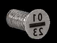
DATE MARKING, AIR VALVES D-10
MICRODATERS
D T F +.25 -.00 +.25 -.00 D T F +.25 -.00 +.25 -.00 CATALOG NUMBER D L A M C F T S WIDTH X DEPTH BLANK CAT. NO. MD02 2 5 .45 M1.4x0.3 .50 1.14 1.4 .38 x .25 MD02-B MD03 3 5 .76 M1.8x0.35 .75 1.52 1.8 .38 x .38 MD03-B MD04 4 6 .89 M2.5x0.45 1.0 1.65 2.7 .38 x .38 MD04-B
03 23 04 23 05 23 06 23 07 23 08 22 09 23 10 23 11 23 12 23 01 24 02 24 05 23 D C 45˚ L A S M .07mm - .12mm Deep 52 ±2 HRC 03 23 04 23 05 23 06 23 07 23 08 22 09 23 10 23 11 23 12 23 01 24 02 24 23 D A S 52 ±2 HRC CAD insertion point M 420 Stainless (1.4034) H 50-54 HRC
®
Blank (-B)
DATE STAMPS
LG SERIES: LARGE MOLD, STRUCTURAL FOAM/BLOW MOLDS
Brass:
Steel:
Plug Styles: Recessed Lettering
Months
Cat #: DLB-Diam (Brass) DLS-Diam (Steel)
Ex.: DLB40, DLS40
Days
Cat #: DLBL-Diam (Brass)
DLSL-Diam (Steel)
Ex.: DLBL40, DLSL40
Year
Cat #: DLBY-Diam – Starting Year* (Brass)
DLSY-Diam – Starting Year* (Steel)
Ex.: DLBY40-23, DLSY40-23
Plug Styles: Recessed Lettering
Arrow Only
Cat #: DLBP-Diam – AO (Brass)
DLSP-Diam – AO (Steel)
Ex.: DLBP40-AO, DLSP40-AO
Year
Cat #: DLBP-Diam – Year* (Brass)
DLSP-Diam – Year* (Steel)
Ex.: DLBP40-23, DLSP40-23
To Order:
Ring Styles: Raised Lettering
Months
Cat #: DLBR-Diam (Brass)
DLSR-Diam (Steel)
Ex.: DLBR40, DLSR40
Days
Cat #: DLBRL-Diam (Brass)
DLSRL-Diam (Steel)
Ex.: DLBRL40, DLSRL40
Year
Cat #: DLBRY-Diam – Starting Year* (Brass)
DLSRY-Diam – Starting Year* (Steel)
Ex.: DLBRY40-23, DLSRY40-23
Plug Styles: Raised Lettering
Arrow Only
Cat #: DLBRP-Diam – AO (Brass)
DLSRP-Diam – AO (Steel)
Ex.: DLBRP40-AO, DLSRP40-AO
Year
Cat #: DLBRP-Diam – Year* (Brass)
DLSRP-Diam – Year* (Steel)
Ex.: DLBRP40-23, DLSRP40-23
• Specify catalog number as shown above for the different style plugs or rings.
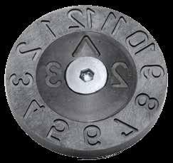
• Where years are specified (*), any year can be ordered by changing the suffix. Example: DLBP15-23 or DLSP15-24.
• Special configurations are available. Contact Customer Service for more information.
DATE MARKING, AIR VALVES D-11
D C M H RAISED HEIGHT 15 10 M3 x 0.5 0.5 20 13 M3 x 0.5 1.0 30 19 M4 x 0.7 1.0 40 25 M5 x 0.8 1.0
Recessed Lettering 5 10 .5mm Deep 5 Thread for removal (M+1mm) M removal ±0.1 ±0.1 18 19 20 12 61 71 D C +0.0 -0.1 Raised Lettering 10 H M 10 5 M Thread for removal (M+1mm) ±0.1 18 19 20 12 61 71 D C +0.0 -0.1 2 6 27 82 32 42 25 2 6 27 82 32 42 25 3 2 3 2
insertion point
CAD
M Ms 58
M O-1 (1.2510) H 52-56 HRC
RECYCLE INSERTS
APPLICATION GUIDELINES
• To avoid damage to face, press insert into hole using a brass or plastic mallet.
• Contact Customer Service for pricing and availability of other sizes or material engraving.

DATE MARKING, AIR VALVES D-12
SPI & ASTM STANDARDS H7 ±0.02mm D Clearance for SHCS or to drive out insert L 7 6 5 4 3 2 1 0 7 5 4 3 2 1 0 6 C D M L 50 ± 2 HRC Etching .3mm (.012") Deep 1/2 L m6 D SPI CATALOG NUMBER ASTM CATALOG NUMBER D MATERIAL CODE MATERIAL L C M RI-10-0 RIS-10-0 10mm (.3937”) N/A BLANK 12 mm (.4724”) 6 mm (.2362”) M5 x .08 RI-10-1 RIS-10-1 1 POLYETHYLENE TEREPHTHALATE RI-10-2 RIS-10-2 2 HIGH DENSITY POLYETHYLENE RI-10-3 RIS-10-3 3 POLYVINYL CHLORIDE RI-10-4 RIS-10-4 4 LOW DENSITY POLYETHYLENE RI-10-5 RIS-10-5 5 POLYPROPYLENE RI-10-6 RIS-10-6 6 POLYSTYRENE RI-10-7 RIS-10-7 7 OTHER RI-16-0 RIS-16-0 16mm (.6299”) N/A BLANK 14 mm (.5518”) 10 mm (.3937”) M6 x 1.0 RI-16-1 RIS-16-1 1 POLYETHYLENE TEREPHTHALATE RI-16-2 RIS-16-2 2 HIGH DENSITY POLYETHYLENE RI-16-3 RIS-16-3 3 POLYVINYL CHLORIDE RI-16-4 RIS-16-4 4 LOW DENSITY POLYETHYLENE RI-16-5 RIS-16-5 5 POLYPROPYLENE RI-16-6 RIS-16-6 6 POLYSTYRENE RI-16-7 RIS-16-7 7 OTHER RI-20-0 RIS-20-0 20mm (.7874”) N/A BLANK 16 mm (.6299”) 12 mm (.4724”) M6 x 1.0 RI-20-1 RIS-20-1 1 POLYETHYLENE TEREPHTHALATE RI-20-2 RIS-20-2 2 HIGH DENSITY POLYETHYLENE RI-20-3 RIS-20-3 3 POLYVINYL CHLORIDE RI-20-4 RIS-20-4 4 LOW DENSITY POLYETHYLENE RI-20-5 RIS-20-5 5 POLYPROPYLENE RI-20-6 RIS-20-6 6 POLYSTYRENE RI-20-7 RIS-20-7 7 OTHER CAD insertion point M 420 Stainless (1.4034) H 50-54 HRC ASTM STANDARD
SPI
STANDARD
APPLICATION GUIDELINES
• Assemblies feature corrosion-resistant stainless steel spring.
• Operating Pressure: 29 psi min. / 140 psi max.
• Maximum Mold Temperature: 265˚F (130˚C)
• Press-fit installation required.
• Avoid machining on the front face.
• The activation of the Air Valve should occur at, or slightly before, part ejection.
• The air pressure must end prior to injection, allowing the spring to retract the piston. Failure to do so may allow molten material to enter into the valve, causing damage to the valve or cavity.
AIR VALVES
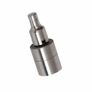
DATE MARKING, AIR VALVES D-13 CATALOG NUMBER D A B C1 L MM Inch MM Inch MM Inch MM Inch MM Inch AV-08 8 .3149 +.0006 +.0002 6.5 .256 11 .433 6 .24 24 1.0 AV-12 12 .4724 +.0007 +.0003 9.7 .382 18 .708 8 .32 34 1.4 AV-18 18 .7086 +.0007 +.0003 14.8 .583 22 .866 12 .47 46 1.8 C +.005 -.000 B C1 +.000 -.001 +.03 +.08 B +.000 -.001 DA B L +.001 -.000 53 ±1 HRC .04 49 ±1 HRC C1 Do not machine or polish the parting line surface of the valve CATALOG NUMBER C AV-08 .265 AV-12 .354 AV-18 .551 Suggested Machining Diameters C +.005 -.000 B C1 +.000 -.001 +.03 +.08 B +.000 -.001 DA B L +.001 -.000 53 ±1 HRC .04 49 ±1 HRC Do not machine or polish the parting line surface of the valve CAD insertion point M 420 Stainless (1.4034) H Body: 52-54 HRC, Plunger: 48-50 HRC (DLC Coated)
APPLICATION GUIDELINES
• Operating Pressure: 80 psi min. / 100 psi max.
• Maximum Mold Temperature: 285˚F (140˚C)
• Avoid machining on the front face.
• The activation of the Air Poppet should occur at, or slightly before, part ejection.
• The air pressure must end prior to injection, allowing the spring to retract the piston. Failure to do so may allow molten material to enter into the valve, causing damage to the poppet or cavity.
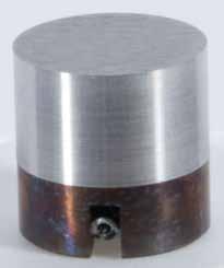
Inch Standard
The Repair Kit includes a spring and pin.
Metric Standard
DATE MARKING, AIR VALVES D-14
CATALOG NUMBER D ± .0002 B C T L +.000 -.002 REPAIR KIT CATALOG NUMBER APV-25 .250 .215 3/16 .06 .375 APVR-25 APV-37 .375 .325 9/32 .07 .375 APVR-37 APV-50 .500 .437 3/8 .10 .500 APVR-50 APV-75 .750 .656 9/16 .15 .750 APVR-75 APV-100 1.000 .875 3/4 .20 1.000 APVR-100 APV-150 1.500 1.312 1 .30 1.500 APVR-150 CATALOG NUMBER D +.003 -.005 B C T L +.00 -.03 REPLACEMENT SPRING CATALOG NUMBER APV-06 6 5 4 1 12 APVR-06 APV-08 8 6.5 5 APVR-08 APV-10 10 8 7 APVR-10 APV-12 12 10 8 APVR-12 APV-16 16 13 12 20 APVR-16 M 420 Stainless (1.4034) H 40-44 HRC M 420 Stainless (1.4034) H 52-54 HRC
AIR POPPETS
CAD insertion point L T D B C Clearance to drive out insert if needed. Pocket Pocket
COOLING PRODUCTS
Pipe Check Baffles Jumper Baffles
Reverse Flow Baffles Cascade: Nipple Type
Prefix: PC Prefix: SB, TB Prefix: JBA Prefix: RFB Prefix: NC Page: E-6
Cascade: High Flow Cascade: Rear Load Cascade: RL Quick Cplr. Cascade: Hex Key Cascade: Quick Coupler Prefix: HFC Prefix: RLN Prefix: RLQC Prefix: HKC, CC Prefix: QC
E-7 Page: E-8 Page: E-9 Page: E-10
Bubbler Base Inlet Cascade Metric Tubes: High Flow Tubes: High Flow, Hex Tubes: Piston, Brass

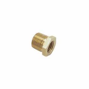


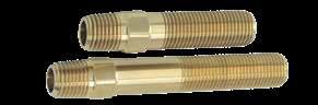
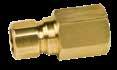
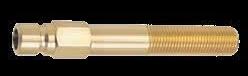

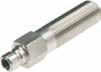
Prefix: BBL Prefix: CF Prefix: HFTM, HEXM Prefix: HFT, HEXT Prefix: PT, T
E-12 Page: E-14
E-15 Page: E-16
O-Rings Pipe Plugs Extension Plugs Connector Plugs Socket Connectors
Prefix: OR Prefix: BR, ST, SS Prefix: Numeral Prefix: Numeral Prefix: SC
E-17 Page: E-21
E-24
E-25
Connector Plugs: Keyed Socket Conn. Keyed Safety Clips Adjustable Hex Nipples Hex Key Ext. Pipes


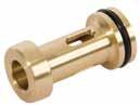
Prefix: Numeral, Suffix: -K Prefix: SC Prefix: APN Prefix: HKEPN Page: E-26 Page: E-27 Page: E-28
Elbows: Hex Key Pipe Nipples Push-Lok Hose Plugs: Water Blockers Plugs: Threadless
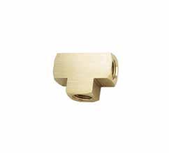
Prefix: HK, HKEE, HKL Prefix: BPN, GPN Prefix: WJH Prefix: WB Page: E-29 Page: E-30 Page: E-30
Diverting Rods & Plugs Water Jumpers Water Jumpers: Swivel Elbows: Hex, Extension Hose Barbs & Splicers

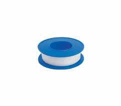
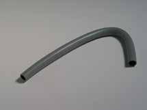

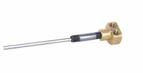

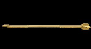
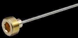
Prefix: DR Prefix: WJ
Prefix: HELS, HELB Prefix: MB, FB, HS
Page: E-33 Page: E-34 Page: E-37
Comb. Hose Inserts Clamps & Tape Tees & Elbows
Reducers & Couplings
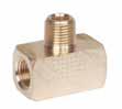

Prefix: Numeral Prefix: CP, HC, TT Prefix: T, MT, ELS, EL, Prefix: RB, MR, C, HN Page: E-38 Page: E-39 Page: E-40 Page: E-41

Page:
Page: E-11
Page:
Page:
Page:
Page:
Page:
PIPE THREAD DATA
The table below lists standard pipe sizes along with the actual O.D. and I.D. for each size. The nominal size of any pipe does not in fact refer to either the outside diameter (O.D.) or the inside diameter (I.D.) of the pipe. Actual size drawings of pipes from 1/16” to 3/4” are shown below. Note: Nominal Pipe Size, Pipe Size, and Pipe Tap Size all refer to an NPT thread.
The Thread Engagement column (“E”) can be used to determine the length of the component required to properly assemble when fully tightened. The drawing above illustrates this measurement.
PIPE CHECK
M
Hard
MOLD-READY COOLING PRODUCTS
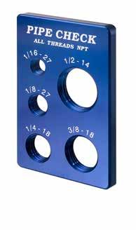
Progressive Components can provide standard items cut to length and ready for installation in the mold. These include Tubes, Extension Plugs, and Adjustable Pipe Nipples and all are available with sealant on the threads. Additional materials are also available on select components. Please refer to the individual pages within this section for more details.
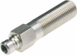
COOLING PRODUCTS E-1
1/16 NPT 1/8 NPT 1/4 NPT 3/8 NPT 1/2 NPT 3/4 NPT PIPE SIZE THREADS PER INCH OUTSIDE DIAMETER OF PIPE INSIDE DIAMETER OF PIPE TAP DRILL SIZE WITHOUT REAM TAP DRILL SIZE WITH REAM E THREAD ENGAGEMENT 1/16 27 .312 .209 1/4 15/64 .250 1/8 27 .405 .269 11/32 21/64 .250 1/4 18 .540 .364 7/16 27/64 .300 3/8 18 .675 .493 9/16 9/16 .300 1/2 14 .840 .622 45/64 11/16 .420 3/4 14 1.050 .824 29/32 57/64 .545 1 11-1/2 1.315 1.049 1-9/64 1-1/8 .661 1-1/4 11-1/2 1.660 1.380 1-31/64 1-15/32 .681 1-1/2 11-1/2 1.900 1.610 1-23/32 1-45/64 .681 2 11-1/2 2.375 2.067 2-3/16 2-11/64 .697 CATALOG NUMBER DESCRIPTION PC-100 Pipe Thread Check E
For an application review, contact tech@procomps.com. anodized aluminum
BLADE MATERIAL
ALTERNATIVE CONFIGURATIONS AVAILABLE
• Straight Baffle Blade Material: Order according to the chart at left. Material is sold in 36” lengths, and other lengths can be provided upon request.
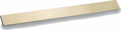
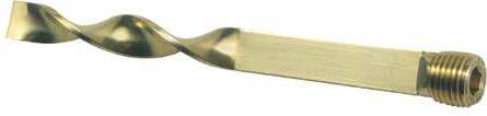
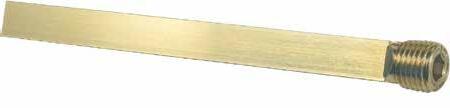
• For Baffles with brass blades and stainless steel pipe plugs, add “-SS” to the end of the catalog number. Ex. SB25L5-SS or TB75L12-SS. Call for pricing on 1-1/4 baffles with stainless steel pipe plugs.
• Baffles can be ordered cut to any length, in any quantity. To order, specify the prefix and plug size and the required length. For Turbo Baffles, the closest straight length (S) is used, but can be provided to a different length, upon request. Ex. SB25L6.25 or TB37L5.75-SS (with a 2” “S” dimension)
• BSPT plug baffles are sold separately on page E-3.
E-2 BAFFLES NPT SERIES B P L B P L S Straight Turbo CATALOG NUMBER B BLADE THICKNESS BLADE WIDTH -.005 -.010 BM06 .057 .250 BM12 .057 .312 BM25 .085 .437 BM25-B .085 .421 BM37 .093 .562 BM50 .093 .687 BM75 .093 .937 BM75-B .093 .906 BM100 .093 1.125 BM125 .093 1.484 CATALOG NUMBER P PLUG SIZE (NPT) L S STRAIGHT LENGTH B BLADE THICKNESS BLADE WIDTH -.005 -.010 TB06L4 1/16-27 4 2 .057 .250 TB06L8 1/16-27 8 4 .057 .250 TB06L12 1/16-27 12 6 .057 .250 TB12L4 1/8-27 4 2 .057 .312 TB12L8 1/8-27 8 4 .057 .312 TB12L12 1/8-27 12 6 .057 .312 TB25L5 1/4-18 5 2 .085 .437 TB25L10 1/4-18 10 4 .085 .437 TB25L15 1/4-18 15 6 .085 .437 TB37L6 3/8-18 6 2 .093 .562 TB37L12 3/8-18 12 4 .093 .562 TB37L18 3/8-18 18 6 .093 .562 TB50L8 1/2-14 8 3 .093 .687 TB50L16 1/2-14 16 5 .093 .687 TB75L12 3/4-14 12 4 .093 .937 TB75L20 3/4-14 20 6 .093 .937 TB100L16 1-11 1/2 16 5 .093 1.125 TB100L24 1-11 1/2 24 8 .093 1.125 TB125L16 1 1/4-11 1/2 16 5 .093 1.484 TB125L24 1 1/4-11 1/2 24 8 .093 1.484 CATALOG NUMBER P PLUG SIZE (NPT) L B BLADE THICKNESS BLADE WIDTH -.005 -.010 SB06L4 1/16-27 4 .057 .250 SB06L8 1/16-27 8 .057 .250 SB06L12 1/16-27 12 .057 .250 SB12L4 1/8-27 4 .057 .312 SB12L8 1/8-27 8 .057 .312 SB12L12 1/8-27 12 .057 .312 SB25L5 1/4-18 5 .085 .437 SB25L10 1/4-18 10 .085 .437 SB25L15 1/4-18 15 .085 .437 SB37L6 3/8-18 6 .093 .562 SB37L12 3/8-18 12 .093 .562 SB37L18 3/8-18 18 .093 .562 SB50L8 1/2-14 8 .093 .687 SB50L16 1/2-14 16 .093 .687 SB75L12 3/4-14 12 .093 .937 SB75L20 3/4-14 20 .093 .937 SB100L16 1-11 1/2 16 .093 1.125 SB100L24 1-11 1/2 24 .093 1.125 SB125L16 1 1/4-11 1/2 16 .093 1.484 SB125L24 1 1/4-11 1/2 24 .093 1.484 B P L B P L S
COOLING PRODUCTS
CAD insertion point
M Brass
M Brass
ALTERNATIVE CONFIGURATIONS AVAILABLE
• For Baffles with brass blades and stainless steel pipe plugs, add “-SS” to the end of the catalog number and contact Customer Service for pricing. Ex. SB25L5-BSP-SS or TB75L12-BSP-SS
• Baffles can be ordered cut to any length, in any quantity. To order, specify the prefix and plug size and the required length. For Turbo Baffles, the closest straight length (S) is used, but can be provided to a different length, upon request. Ex. SB25L6.25-BSP or TB37L5.75-BSP-SS (with a 2” “S” dimension)
• Straight Baffle Material is available on page E-2.
• End of Baffle has a ring for identification.
COOLING PRODUCTS E-3
BSPT
B P L B P L S B P L B P L S CATALOG NUMBER P PLUG SIZE (BSPT) L S STRAIGHT LENGTH B BLADE THICKNESS BLADE WIDTH -.005 -.010 TB12L4-BSP 1/8-28 4 2 .057 .312 TB12L8-BSP 1/8-28 8 4 .057 .312 TB12L12-BSP 1/8-28 12 6 .057 .312 TB25L5-BSP 1/4-19 5 2 .085 .421 TB25L10-BSP 1/4-19 10 4 .085 .421 TB25L15-BSP 1/4-19 15 6 .085 .421 TB37L6-BSP 3/8-19 6 2 .093 .562 TB37L12-BSP 3/8-19 12 4 .093 .562 TB37L18-BSP 3/8-19 18 6 .093 .562 TB50L8-BSP 1/2-14 8 3 .093 .687 TB50L16-BSP 1/2-14 16 5 .093 .687 TB75L12-BSP 3/4-14 12 4 .093 .906 TB75L20-BSP 3/4-14 20 6 .093 .906 TB100L16-BSP 1-11 16 5 .093 1.125 TB100L24-BSP 1-11 24 8 .093 1.125 CATALOG NUMBER P PLUG SIZE (BSPT) L B BLADE THICKNESS BLADE WIDTH -.005 -.010 SB12L4-BSP 1/8-28 4 .057 .312 SB12L8-BSP 1/8-28 8 .057 .312 SB12L12-BSP 1/8-28 12 .057 .312 SB25L5-BSP 1/4-19 5 .085 .421 SB25L10-BSP 1/4-19 10 .085 .421 SB25L15-BSP 1/4-19 15 .085 .421 SB37L6-BSP 3/8-19 6 .093 .562 SB37L12-BSP 3/8-19 12 .093 .562 SB37L18-BSP 3/8-19 18 .093 .562 SB50L8-BSP 1/2-14 8 .093 .687 SB50L16-BSP 1/2-14 16 .093 .687 SB75L12-BSP 3/4-14 12 .093 .906 SB75L20-BSP 3/4-14 20 .093 .906 SB100L16-BSP 1-11 16 .093 1.125 SB100L24-BSP 1-11 24 .093 1.125
M Brass M Brass Straight Turbo
BAFFLES
SERIES
CAD insertion point
JUMPER BAFFLES
APPLICATION GUIDELINES
• Jumper Baffles enable water routing via interconnected baffles.
• Simplifies design and machining of a complex circuit, reducing the number of feedlines required.
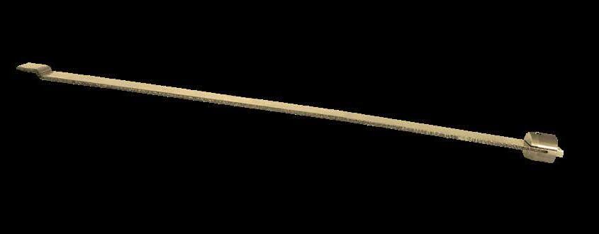
• Replacement Jumper Plug items are available. Assemblies include the Jumper Plug, (2) Set Screws, and a Brass Pipe Plug.
• For application assistance, contact tech@procomps.com.
Installation:
1. Install the Jumper Blade so its shoulder rests against the intersection of the Straight Baffle and mark this location.
2. Calculate the distance from this marked location by adding the S dimension of the Jumper Plug to the distance that the plug will be recessed into the insert. Cut the Jumper Blade to this length.
3. Attach the Jumper Blade to the Jumper Plug using the two set screws.
4. Install the assembly into the waterline until it rests against the Straight Baffle. Then, insert the Pipe Plug until it is secured against the Jumper Plug.
E-4
COOLING PRODUCTS
CATALOG NUMBER P PIPE PLUG SIZE (NPT) B W -.005 -.010 L OAL S C F SET SCREW SIZE JBA12 1/8 .06 .312 .66 12.50 .50 .242 .25 #4-40 x 3/32 JBA25 1/4 .06 .437 .90 12.63 .63 .352 .30 #6-32 x 1/8 JBA37 3/8 .06 .562 .90 12.63 .63 .477 .43 #10-32 x 1/8 JBA50 1/2 .06 .687 1.06 12.75 .75 .602 .52 #10-32 x 3/16 JBA75 3/4 .09 .937 1.09 12.75 .75 .852 .70 #10-32 x 3/16 W P C OAL L S B F IN OUT NPT Thread for Pipe Plug Mark Location Jumper Blade Intersecting Straight Baffle S + Plug Recess Cut Location S Plug Recess Pipe Plug Jumper Plug Marked Location IN OUT Standard Straight Baffle Jumper Baffle CAD insertion point M Brass
REVERSE FLOW BAFFLES
Reverse Flow Baffles enable the feed line to a baffle to be located opposite the plug end of the baffle to avoid interfering with bushing holes, return pin holes, etc.
• Provides an alternative to circuits with long cross plate gun drilled lines and placement of in-line diverters, simplifying design, machining, and waterline cleaning.
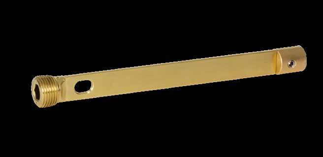
APPLICATION GUIDELINES
1. Install the Reverse Flow Baffle into the waterline and measure the distance the Baffle extends out of the plate, “M” as shown below.
2. Remove the Reverse Flow Plug and cut the measured length from the end of the Baffle including any recess required.
3. Re-attach the Reverse Flow Plug to the Baffle using the two set screws.
4. Install the assembly into the water line, ensuring a tight seal and proper orientation.
E-5
OAL S SL W Set Screw P B C E SW
CATALOG NUMBER P PIPE PLUG SIZE (NPT) OAL (REF) B W -.005 -.010 S SL SW C E SET SCREW SIZE (2) RFB06L8 1/16 8.16 .057 .250 .44 .18 .13 .38 .16 #4-40 x 3/32 RFB12L8 1/8 8.23 .057 .312 .44 .22 .16 .50 .23 #4-40 x 3/32 RFB25L10 1/4 10.25 .085 .437 .62 .35 .19 .62 .25 #8-32 x 1/8 RFB37L12 3/8 12.28 .093 .562 .62 .41 .28 .75 .28 #10-32 x 3/16 RFB50L16 1/2 16.28 .093 .687 .75 .50 .31 .75 .28 1/4-20 x 3/16 RFB75L20 3/4 20.38 .093 .937 .75 .77 .44 .87 .38 1/4-20 x 3/8 RFB100L24 1 24.38 .093 1.125 .87 1.00 .50 .87 .38 1/4-20 x 3/8 RFB125L24 1-1/4 24.50 .093 1.484 1.35 1.22 .50 1.00 .50 1/4-20 x 1/2 IN OUT M Thru Slot Baffle Reverse Flow Plug Cut Location M+ Baffle Recess CAD insertion point M Brass
M Head: Brass, Tube: Brass, 2” Long Pipe Nipple: Stainless Steel
insertion point
ALTERNATIVE CONFIGURATIONS AVAILABLE
• Cascade Heads are available with thread sizes to accept High Flow Tubes. To order, specify -HFT at the end of the catalog number for Cascade assemblies or for Heads only. Ex. NC1818-HFT or NCH1818-HFT. (Note: NC3438 is not available with the High Flow Tube option.)
• Cascade heads are available manufactured from stainless steel. To order, add “-SS” to the end of the catalog number for Cascade assemblies or for Heads only. Ex. NC1818-SS or NCH1818-SS

• These Cascades can also be used with Adjustable Hex Nipples instead of Pipe Nipples. Refer to page E-28 for available sizes and lengths.
• For complete Tube specifications, refer to page E-16.
E-6 H L M C E P (3) A
T X
CATALOG NUMBER M PIPE NPT P IN/OUT NPT H E C A L T BRASS TUBE CATALOG # (INCLUDED) X TUBE END HEAD ONLY CATALOG NUMBER NC1816 1/8 1/16 .75 .21 .50 .28 .937 #10-32 T187L12 .90 NCH1816 NC1818 1/8 1/8 .87 .32 .68 .28 1.343 #10-32 T187L12 1.06 NCH1818 NC18181 1/8 1/8 .87 .32 1.00 .28 1.656 #10-32 T187L12 1.18 NCH18181 NC1418 1/4 1/8 1.00 .32 .68 .21 1.343 1/4-28 T250L12 1.05 NCH1418 NC1414 1/4 1/4 1.00 .32 .68 .21 1.343 1/4-28 T250L12 1.08 NCH1414 NC14181 1/4 1/8 1.00 .32 1.00 .43 1.656 1/4-28 T250L12 1.44 NCH14181 NC14141 1/4 1/4 1.00 .32 1.00 .43 1.656 1/4-28 T250L12 1.44 NCH14141 NC3818 3/8 1/8 1.00 .34 1.00 .40 1.687 5/16-24 T312L12 1.44 NCH3818 NC3814 3/8 1/4 1.00 .34 1.00 .40 1.687 5/16-24 T312L12 1.44 NCH3814 NC1214 1/2 1/4 1.25 .40 1.00 .56 1.812 7/16-20 T437L12 1.80 NCH1214 NC3438 3/4 3/8 1.50 .50 1.25 .75 2.250 5/8-18 T625L12 2.20 NCH3438 CAD
12" Long Brass Tube
Brass pipe plug included.
Brass, Tube: Brass, 2” Long Pipe Nipple: Stainless Steel
ALTERNATIVE CONFIGURATIONS AVAILABLE
• For High Flow Cascade assemblies with a stainless steel head, add “-SS” to the end of the catalog number. Ex. HFC1616-SS or HFC3814-SS
• For High Flow Cascade Heads manufactured out of stainless steel, add “-SS” to the end of the head catalog number. Ex. HFH1414-SS or HFH1616-SS
• High Flow Cascades can also be used with Adjustable Hex Nipples instead of Stainless Nipples. Refer to page E-28 for available sizes and lengths.
• For complete High Flow Tube specifications, refer to page E-15.
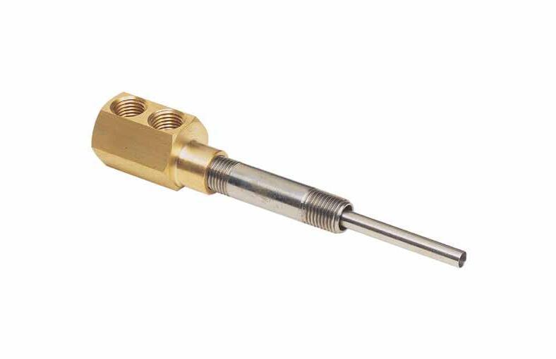
E-7
CASCADES HIGH FLOW
O H T 12"
High
M C X L E P CATALOG NUMBER M PIPE NPT P IN/OUT NPT H O OFFSET E C L T TUBE THREAD HIGH FLOW TUBE CATALOG # (INCLUDED) X TUBE END HEAD ONLY CATALOG NUMBER HFC1616 1/16 1/16 .62 .094 .25 .50 1.25 #10-32 HFT125L12 .88 HFH1616 HFC1818 1/8 1/8 .75 .094 .31 .68 1.62 1/4-28 HFT187L12 1.14 HFH1818 HFC18181 1/8 1/8 .75 .094 .31 1.00 1.93 1/4-28 HFT187L12 1.15 HFH18181 HFC1414 1/4 1/4 1.00 .156 .34 .68 1.87 5/16-24 HFT250L12 1.30 HFH1414 HFC14141 1/4 1/4 1.00 .156 .34 1.00 2.18 5/16-24 HFT250L12 1.55 HFH14141 HFC3814 3/8 1/4 1.12 .125 .34 1.00 2.25 7/16-20 HFT375L12 1.64 HFH3814 HFC1214 1/2 1/4 1.37 .125 .37 1.00 2.37 1/2-20 HFT437L12 1.77 HFH1214 CAD insertion point
M Head:
Long
Flow Tube
M Head: Brass, Tube & Pipe Nipple: Stainless Steel
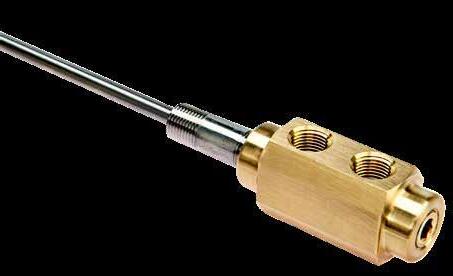
ALTERNATIVE CONFIGURATIONS AVAILABLE
• For Cascade assemblies with a stainless steel head, add “-SS” to the end of the catalog number. Ex. RLNC1618-SS or RLNC18181-SS
• For Cascade Heads manufactured out of stainless steel, add “-SS” to the end of the head catalog number. Ex. RLCNH1618-SS or RLCNH18181-SS
• For complete Piston Tube specifications and longer lengths, refer to page E-16.
APPLICATION GUIDELINES
• Rear Loading Nipple Cascades allow easy access to the Piston Tube.
• Enables positive adjustment of inner tube at assembly.
• Includes 12” long Piston Tube and 2” long Stainless Pipe Nipple.
PRODUCTS E-8
REAR LOADING NIPPLE H L M C E P (3) A
Install tube from this end (M) T X CATALOG NUMBER M PIPE NPT P IN/OUT NPT H E C A L PISTON TUBE CATALOG # (INCLUDED) T X TUBE END HEAD ONLY CATALOG NUMBER RLNC1618 1/8 1/16 3/4 .500 5/8 9/32 1.625 PT06-187L12 1/16 .93 RLCNH1618 RLNC1818 1/8 1/8 7/8 .609 11/16 9/32 1.960 PT06-187L12 1/16 1.08 RLCNH1818 RLNC18181 1/8 1/8 7/8 .609 1 9/32 2.218 PT06-187L12 1/16 1.39 RLCNH18181 RLNC1414 1/4 1/4 1 .781 1 7/16 2.562 PT12-250L12 1/8 1.44 RLCNH1414 RLNC1438 3/8 1/4 1 .781 1 7/16 2.562 PT25-312L12 1/4 1.50 RLCNH1438 CAD insertion point
COOLING
CASCADES
12” Stainless High Flow Piston Tube
APPLICATION GUIDELINES
• Rear Load Quick Coupler Cascades allow access to the inner cooling tube without removing the cascade assembly.
• Can be installed and removed without disconnecting cooling lines
M Head: Brass, Tube: Stainless Steel, Seals: Viton
Includes 12” long Piston Tube.
ALTERNATIVE CONFIGURATIONS AVAILABLE
• For Cascade assemblies with a stainless steel head, add “-SS” to the end of the catalog number. Ex. RLQC1814-SS or RLQC1418-SS
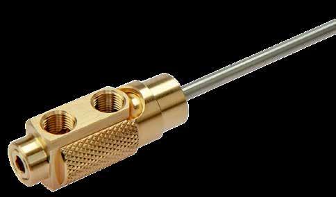
• For Cascade Heads manufactured out of stainless steel, add “-SS” to the end of the head catalog number. Ex. RLQCH1814-SS or RLQCH1418-SS
• For complete Piston Tube specifications and longer lengths, refer to page E-16.
* Uses High Flow Tube PT12-187
** Uses High Flow Tube PT37-375
COOLING PRODUCTS E-9
REAR LOAD QUICK COUPLER Connector (sold separately) P (3) T 12" Long High Flow Piston Tube D C A Y L X H K Install tube from this end (M) CATALOG NUMBER CONNECTOR SERIES M PLUG SIZE NPT P IN/ OUT NPT C A H D L PISTON TUBE CATALOG # (INCLUDED) T X TUBE END Y HEAD ONLY CATALOG NUMBER RLQC1814 200 1/8 1/8 11/16 31/32 13/16 7/8 2.187 PT06-187L12 1/16 1.45 .370 RLQCH1814 RLQC1815 200 1/8 1/8 1 31/32 13/16 7/8 2.500 PT06-187L12 1/16 1.54 .370 RLQCH1815 RLQC1418 300 1/4 1/4 1 1-5/32 1 1-1/8 2.937 PT12-250L12 1/4 1.89 .590 RLQCH1418 RLQC1422 500 1/2 1/4 1-1/4 1-3/8 1-1/4 1-3/8 3.687 PT37-437L12 3/8 2.25 .730 RLQCH1422 RLQC3822 500 1/2 3/8 1-1/4 1-3/8 1-1/4 1-3/8 3.687 PT37-437L12 3/8 2.25 .730 RLQCH3822 CATALOG NUMBER CONNECTOR K MIN. RLQC1814 RLQC1815 251 .32 252 .43 253 .49 RLQC1418 351* .34 352 .42 353 .45 354 .57 RLQC1422 RLQC3822 553** .55 554 .54 556 .57
CASCADES
CAD insertion point
M Head: Brass, Tube: Stainless Steel, 2” Long Pipe Nipple: Stainless Steel
Note: HKC1616 includes a Brass Pipe Nipple
COMPACT
M Head: Brass, Tube: Stainless Steel, 2” Long Pipe Nipple: Stainless Steel
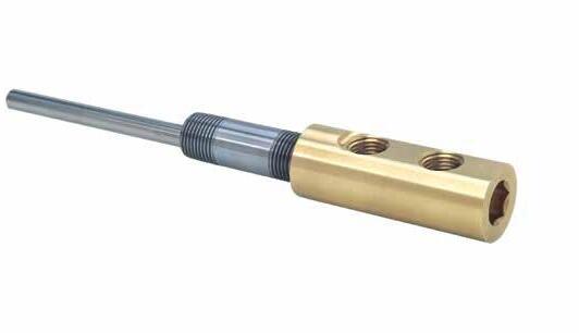
ALTERNATIVE CONFIGURATIONS AVAILABLE
• For Cascade assemblies with a stainless steel head, add “-SS” to the end of the catalog number. Ex. CC3814-SS or HKC1214-SS
• For Cascade Heads manufactured out of stainless steel, add “-SS” to the end of the head catalog number. Ex. CCH1418-SS or HKCH1214-SS
• Both the Hex Key and Compact Cascades can also be used with Adjustable Hex Nipples instead of Stainless Nipples. Refer to page E-28 for available sizes and lengths.
• For complete High Flow Tube specifications, refer to page E-15.

COOLING PRODUCTS E-10 CASCADES HEX KEY Hex Key Size M C A L P T OD 12" Long High Flow Tube X
CATALOG NUMBER M PIPE NPT P IN/ OUT NPT L C A HEX KEY SIZE OD HIGH FLOW TUBE CATALOG # (INCLUDED) T NOMINAL CLEARANCE DRILL X TUBE END HEAD ONLY CATALOG NUMBER HKC1616 1/16 1/16 1.625 .56 .50 5/16 .610 HFT125L12 #10-32 5/8 .89 HKCH1616 HKC1816 1/8 1/16 1.687 .56 .56 3/8 .735 HFT187L12 1/4-28 3/4 .98 HKCH1816 HKC1818 1/8 1/8 1.875 .68 .56 3/8 .860 HFT187L12 1/4-28 7/8 1.00 HKCH1818 HKC18181 1/8 1/8 2.187 1.00 .56 3/8 .860 HFT187L12 1/4-28 7/8 1.20 HKCH18181 HKC1418 1/4 1/8 2.187 .68 .81 1/2 .985 HFT250L12 5/16-24 1 1.32 HKCH1418 HKC14181 1/4 1/8 2.500 1.00 .81 1/2 .985 HFT250L12 5/16-24 1 1.38 HKCH14181 HKC1414 1/4 1/4 2.312 .68 .87 1/2 .985 HFT250L12 5/16-24 1 1.33 HKCH1414 HKC14141 1/4 1/4 2.625 1.00 .87 1/2 .985 HFT250L12 5/16-24 1 1.48 HKCH14141 HKC3814 3/8 1/4 2.625 1.00 .87 1/2 .985 HFT312L12 3/8-24 1 1.56 HKCH3814 HKC1214 1/2 1/4 2.812 1.00 1.00 1/2 1.235 HFT375L12 7/16-20 1-1/4 1.73 HKCH1214 CATALOG NUMBER M PIPE NPT P IN/ OUT NPT H A B C E L HIGH FLOW TUBE CATALOG # (INCLUDED) T X TUBE END HEAD ONLY CATALOG NUMBER CC1816 1/8 1/16 .93 .21 .437 .50 .625 1.00 HFT187L12 1/4-28 .60 CCH1816 CC1418 1/4 1/8 1.25 .31 .625 .68 .750 1.25 HFT250L12 5/16-24 .82 CCH1418 CC1414 1/4 1/4 1.50 .37 .750 .75 .875 1.50 HFT250L12 5/16-24 .90 CCH1414 CC3814 3/8 1/4 1.50 .37 .750 .75 1.000 1.50 HFT312L12 3/8-24 .92 CCH3814 CC1214 1/2 1/4 1.75 .37 .750 1.0 1.187 1.75 HFT375L12 7/16-20 1.13 CCH1214 CC3438 3/4 3/8 2 .437 .875 1.125 1.375 1.875 HFT500L12 9/16-18 1.21 CCH3438 H L A C P B E M T 12" Long High Flow Tube X
CAD insertion point
CAD insertion
point
H
Connector (sold separately) 12" Long High Flow Tube X D C AK L
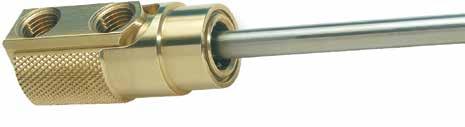
CATALOG NUMBER CONNECTOR SERIES P PIPE TAP SIZE NPT C A H D L HIGH FLOW TUBE CATALOG # (INCLUDED) T X TUBE END HEAD ONLY CATALOG NUMBER QC1819 200 1/8 .687 .968 .812 .875 1.937 HFT187L12 1/4-28 1.45 QCH1819 QC1822 200 1/8 1.000 .968 .812 .875 2.250 HFT187L12 1/4-28 1.54 QCH1822 QC1421 300 1/4 .687 1.156 1.000 1.125 2.187 HFT250L12 5/16-24 1.63 QCH1421 QC1425 300 1/4 1.000 1.156 1.000 1.125 2.500 HFT250L12 5/16-24 1.70 QCH1425 QC1431 500 1/4 1.250 1.375 1.250 1.375 3.125 HFT437L12 1/2-20 2.20 QCH1431 QC3831 500 3/8 1.250 1.375 1.250 1.375 3.125 HFT437L12 1/2-20 2.20 QCH3831 CATALOG NUMBER CONNECTOR K MIN. QC1819 QC1822 251 .32 252 .43 253 .49 QC1421 QC1425 351* .34 352 .42 353 .45 354 .57 QC1431 QC3831 553** .55 554 .54 556 .57 CAD insertion point
* Uses High Flow Tube HFTJ187.
** Uses High Flow Tube HFTJ375.
COOLING PRODUCTS E-11
CASCADES QUICK COUPLER
Longer High Flow Tubes and complete tube specifications can be found on page E-15. P (3) T
M Cascade Head: Brass, Tube: Stainless Steel, Seals: Viton
BUBBLER BASE ™
High Flow Tubes and Hex Series Tubes are sold separately on page E-15.
APPLICATION GUIDELINES
• The Bubbler Base allows for positive positioning of cooling tubes over previous methods.
• The compact design enables minimal center-to-center pin locations.
• Each Bubbler Base includes the O-Ring to ensure a positive seal within the core pin.
• Maximum temperature: 400˚F (200˚C)
• Utilize the largest diameter tube possible and match the inlet diameter’s area.
• Core Pin diameter head should be large enough to incorporate a standard O-ring to seal around the tube.
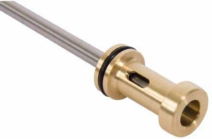
• Water line location can be anywhere within the relief channel.
• To remove the Bubbler Base/Tube without damage, slip a pipe nipple around the tube that matches the “P” thread size, and fasten into the base as shown.
• The Bubbler Base can be removed by hand or by wrench on the pipe nipple (P).
• The quantity of Bubbler Bases and Tubes in line is dependent upon the mold design application and waterline calculations. For assistance in determining the optimal waterline circuit, please contact tech@procomps.com.
COOLING PRODUCTS E-12
.03 Chamfer IN Drain Channel +.001 -.000 Break all lead-in corners for O-Ring Standard High Flow or Hex Series High Flow Tube L +.002 -.000 D CATALOG NUMBER D L C K S H STOP FOR HIGH FLOW TUBE T P PIPE THREAD FOR REMOVAL COMPATIBLE HIGH FLOW TUBE COMPATIBLE HEX SERIES TUBE BBL05 .374 .750 .35 .19 .160 .45 #5-44 #10-32 HFT078 / HFT094 HEXT078 / HEXT094 BBL10 .436 1.000 .55 .23 .190 .61 #10-32 1/4-28 HFTJ078 / HFT125 HEXTJ094 / HEXT125 BBL25 .560 1.250 .72 .27 .255 .72 1/4-28 1/16-27 NPT HFTJ125 / HFT187 HEXTJ125 / HEXT187 BBL31 .748 1.500 .98 .27 .285 .92 5/16-24 1/8-27 NPT HFTJ187 / HFT250 HEXTJ187 / HEXT250 US Patent No. 9,248,597
Drain (Out) Feed (In) S T L H P K C D Drainage Slots (3) .03 Chamfer IN Drain Channel +.001 -.000 Break all lead-in corners for O-Ring Standard High Flow or Hex Series High Flow Tube L +.002 -.000 D P Maintenance/Removal Application CAD insertion point
M Brass with Viton O-Ring
APPLICATION GUIDELINES
• The Inlet Cascade Fitting can be used when waterline space is limited, such as under a runner and between ejector pins or to provide a water circuit in a slide.
• The Inlet Cascade Fitting attaches to standard Tubes and Extension or Connector Plugs, eliminating the machining required for an extra “in” line to achieve consistent cooling.
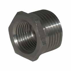
COOLING PRODUCTS E-13 INLET CASCADE ™ CASCADE TUBE FITTING .688 N .12 H .03 P M T D Inlet Cascade Method Previous Method Slide Application Inlet Cascade Fitting Connector Plug Baffle Connector Plug Extension Plug C High Flow Tube B High Flow Tube T M .688 .12 H .03 P D +.20 -.00 F CATALOG NUMBER M WATERLINE NPT P NPT T TUBE THREAD N H HEX D HEX CLEARANCE F HEX C’BORE COMPATIBLE HIGH FLOW TUBE B DIA. C DIA. RECOMMENDED CONNECTOR PLUG CF25 1/4 1/8 5/16-24 .33 .56 1.00 .430 HFT250 7/16 5/16 251, 351 CF37 3/8 1/4 3/8-24 .24 .68 1.12 .430 HFT312 9/16 7/16 352 CF50 1/2 3/8 7/16-20 .24 .87 1.50 .330 HFT375 11/16 9/16 553 Inlet Cascade Fitting Connector Plug Baffle Connector Plug C High Flow Tube B Inlet Cascade Fitting Connector Plug Baffle Connector Plug Extension Plug C High Flow Tube B High Flow Tube M 303 Stainless Steel H 18-22 HRC CAD insertion point
HIGH FLOW TUBES METRIC
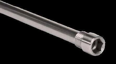
• Tubes can be ordered cut to a specific length or provided in longer lengths. To order, replace the length on any given catalog number with the desired length. Ex: HFTM79L200.
HEX SERIES TUBES
• Tubes can be ordered cut to a specific length or provided in longer lengths. To order, replace the length on any given catalog number with the desired length. Ex: HEXM79L200.
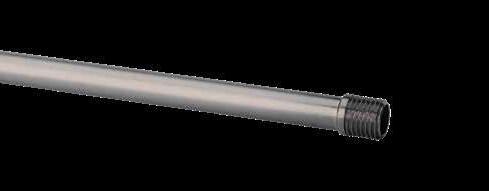
E-14
COOLING PRODUCTS
METRIC T D S H Wrench Size 450mm CATALOG NUMBER TUBE O.D. TUBE I.D. T S SHOULDER LENGTH H THREAD LENGTH HFTM18L450 1.8 1.5 M4 x .7 5 4 HFTM23L450 2.3 1.9 M5 x .8 6 5 HFTM32L450 3.2 2.8 M6 x 1.0 7 6 HFTM48L450 4.8 4.2 M8 x 1.25 10 8 HFTM64L450 6.4 5.8 M10 x 1.5 12 10 HFTM79L450 7.9 7.3 M12 x 1.75 14 12 S H 450mm T CAD insertion point M Stainless Steel
Stainless Steel CATALOG NUMBER TUBE O.D. TUBE I.D. T S SHOULDER LENGTH D H HEAD HEIGHT WRENCH SIZE HEXM18L450 1.8 1.5 M4 x .7 8 5 4 3 HEXM23L450 2.3 1.9 M5 x .8 10 6 5 4 HEXM32L450 3.2 2.8 M6 x 1.0 12 8 6 5 HEXM48L450 4.8 4.2 M8 x 1.25 16 10 8 6 HEXM64L450 6.4 5.8 M10 x 1.5 16 12 8 6 HEXM79L450 7.9 7.3 M12 x 1.75 16 14 8 8 CAD insertion point
M
CONFIGURATIONS
ALTERNATIVE CONFIGURATIONS AVAILABLE
ALTERNATIVE
AVAILABLE
HIGH FLOW TUBES
APPLICATION GUIDELINES
• High Flow Tubes are for use with High Flow Cascade Heads, Compact Cascade Heads, Quick Coupling Cascade Heads and Hex Key Cascade Heads.
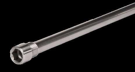
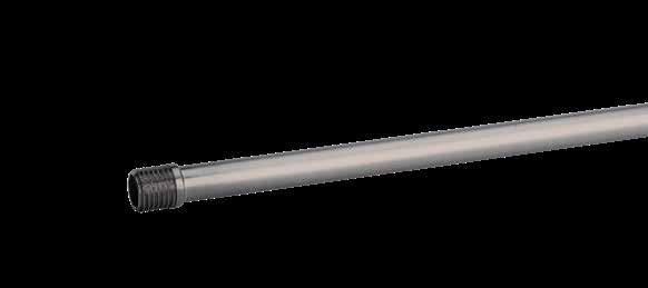
• Tubes can be ordered cut to a specific length or provided in longer lengths. To order, replace the length on any given catalog number with the desired length.
Ex. HFT125L14.5
HEX SERIES TUBES
ALTERNATIVE CONFIGURATIONS AVAILABLE
• Tubes can be ordered cut to a specific length or provided in longer lengths. To order, replace the length on any given catalog number with the desired length. Ex: HEXT312L14.5.
COOLING PRODUCTS E-15
TUBE O.D. TUBE I.D. THREAD SIZE H S 12” LENGTH 18” LENGTH 24” LENGTH 36” LENGTH .072 .060 #5-44 .125 .140 HFT078L12 HFT078L18 HFT078L24 HFT078L36 #10-32 .156 .203 HFTJ078L12 HFTJ078L18 HFTJ078L24 HFTJ078L36 .090 .076 #5-44 .125 .140 HFT094L12 HFT094L18 HFT094L24 HFT094L36 #10-32 .156 .203 HFTJ094L12 HFTJ094L18 HFTJ094L24 HFTJ094L36 .125 .109 #10-32 .156 .203 HFT125L12 HFT125L18 HFT125L24 HFT125L36 1/4-28 .203 .255 HFTJ125L12 HFTJ125L18 HFTJ125L24 HFTJ125L36 .187 .167 1/4-28 .203 .255 HFT187L12 HFT187L18 HFT187L24 HFT187L36 5/16-24 .235 .290 HFTJ187L12 HFTJ187L18 HFTJ187L24 HFTJ187L36 .250 .230 5/16-24 .235 .290 HFT250L12 HFT250L18 HFT250L24 HFT250L36 3/8-24 .296 .359 HFTJ250L12 HFTJ250L18 HFTJ250L24 HFTJ250L36 .312 .288 3/8-24 .296 .359 HFT312L12 HFT312L18 HFT312L24 HFT312L36 7/16-20 .359 .437 HFTJ312L12 HFTJ312L18 HFTJ312L24 HFTJ312L36 .365 .340 7/16-20 .359 .437 HFT375L12 HFT375L18 HFT375L24 HFT375L36 1/2-20 .421 .500 HFTJ375L12 HFTJ375L18 HFTJ375L24 HFTJ375L36 .427 .397 1/2-20 .421 .500 HFT437L12 HFT437L18 HFT437L24 HFT437L36 9/16-18 .421 .500 HFTJ437L12 HFTJ437L18 HFTJ437L24 HFTJ437L36 .500 .444 9/16-18 .421 .531 HFT500L12 HFT500L18 HFT500L24 HFT500L36 5/8-18 .421 .531 HFTJ500L12 HFTJ500L18 HFTJ500L24 HFTJ500L36
TUBE O.D. TUBE I.D. T THREAD WRENCH SIZE S D H HEAD HEIGHT 12” LENGTH 18” LENGTH 24” LENGTH 36” LENGTH .072 .060 #5-44 1/8 .312 .182 .156 HEXT078L12 HEXT078L18 HEXT078L24 HEXT078L36 #10-32 1/8 .406 .245 .187 HEXTJ078L12 HEXTJ078L18 HEXTJ078L24 HEXTJ078L36 .090 .076 #5-44 1/8 .312 .182 .156 HEXT094L12 HEXT094L18 HEXT094L24 HEXT094L36 #10-32 1/8 .406 .245 .187 HEXTJ094L12 HEXTJ094L18 HEXTJ094L24 HEXTJ094L36 .125 .109 #10-32 5/32 .406 .245 .187 HEXT125L12 HEXT125L18 HEXT125L24 HEXT125L36 1/4-28 5/32 .406 .307 .250 HEXTJ125L12 HEXTJ125L18 HEXTJ125L24 HEXTJ125L36 .187 .167 1/4-28 3/16 .500 .307 .250 HEXT187L12 HEXT187L18 HEXT187L24 HEXT187L36 5/16-24 1/4 .562 .370 .281 HEXTJ187L12 HEXTJ187L18 HEXTJ187L24 HEXTJ187L36 .250 .230 5/16-24 1/4 .562 .370 .281 HEXT250L12 HEXT250L18 HEXT250L24 HEXT250L36 3/8-24 5/16 .625 .495 .312 HEXTJ250L12 HEXTJ250L18 HEXTJ250L24 HEXTJ250L36 .312 .288 3/8-24 5/16 .625 .495 .312 HEXT312L12 HEXT312L18 HEXT312L24 HEXT312L36 1/2-20 3/8 .750 .620 .375 HEXTJ312L12 HEXTJ312L18 HEXTJ312L24 HEXTJ312L36 T D S H Wrench Size Length S H Length CAD insertion point CAD insertion point
M Stainless Steel M Stainless Steel
PISTON TUBES
M Tube: High Flow Stainless Steel, Pipe Plug: Stainless Steel

BRASS TUBES
M Half-Hard Tempered Brass
ALTERNATIVE CONFIGURATIONS AVAILABLE
• For Piston Tubes with a brass plug, specify “B” at the end of the catalog numbers. Ex. PT25-250L12B.
• Longer lengths and Piston Tubes cut to length are available. Contact Customer Service for pricing and delivery.
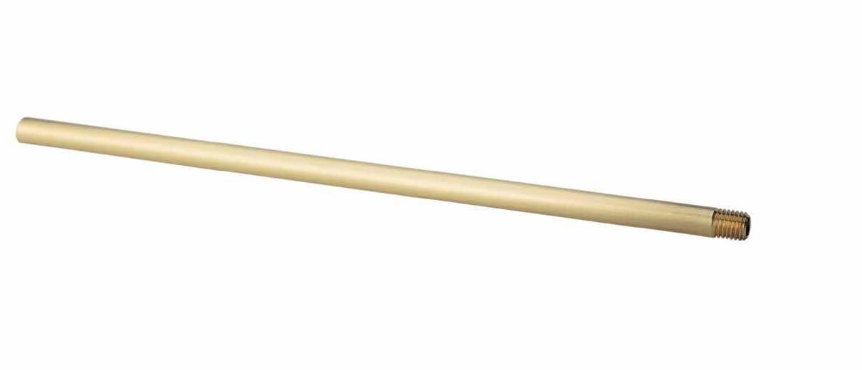
ALTERNATIVE CONFIGURATIONS AVAILABLE
• To order tubes with both ends threaded, add a “T” to the end of the catalog number. Ex. T125L12T
• Tubing is available in stainless steel and threaded both ends. To order, specify “-SST” in the catalog number above. Ex. T125L12-SST. (Note: Not available in 5/8 OD.)
• Longer length tubes or tubes cut to length can be ordered by contacting Customer Service.
COOLING PRODUCTS E-16
P NPT TUBE O.D. TUBE I.D. 12” LENGTH 18” LENGTH 24” LENGTH 36” LENGTH 48” LENGTH 1/16 .072 .060 PT06-078L12 PT06-078L18 PT06-078L24 PT06-078L36 PT06-078L48 .090 .076 PT06-094L12 PT06-094L18 PT06-094L24 PT06-094L36 PT06-094L48 .109 .095 PT06-109L12 PT06-109L18 PT06-109L24 PT06-109L36 PT06-109L48 .125 .109 PT06-125L12 PT06-125L18 PT06-125L24 PT06-125L36 PT06-125L48 .187 .167 PT06-187L12 PT06-187L18 PT06-187L24 PT06-187L36 PT06-187L48 1/8 .125 .109 PT12-125L12 PT12-125L18 PT12-125L24 PT12-125L36 PT12-125L48 .187 .167 PT12-187L12 PT12-187L18 PT12-187L24 PT12-187L36 PT12-187L48 .250 .230 PT12-250L12 PT12-250L18 PT12-250L24 PT12-250L36 PT12-250L48 1/4 .187 .167 PT25-187L12 PT25-187L18 PT25-187L24 PT25-187L36 PT25-187L48 .250 .230 PT25-250L12 PT25-250L18 PT25-250L24 PT25-250L36 PT25-250L48 .312 .288 PT25-312L12 PT25-312L18 PT25-312L24 PT25-312L36 PT25-312L48 3/8 .312 .288 PT37-312L12 PT37-312L18 PT37-312L24 PT37-312L36 PT37-312L48 .365 .340 PT37-375L12 PT37-375L18 PT37-375L24 PT37-375L36 PT37-375L48 .427 .397 PT37-437L12 PT37-437L18 PT37-437L24 PT37-437L36 PT37-437L48 1/2 .365 .340 PT50-375L12 PT50-375L18 PT50-375L24 PT50-375L36 PT50-375L48 .427 .397 PT50-437L12 PT50-437L18 PT50-437L24 PT50-437L36 PT50-437L48 .500 .444 PT50-500L12 PT50-500L18 PT50-500L24 PT50-500L36 PT50-500L48 3/4 .427 .397 PT75-437L12 PT75-437L18 PT75-437L24 PT75-437L36 PT75-437L48 .500 .444 PT75-500L12 PT75-500L18 PT75-500L24 PT75-500L36 PT75-500L48 .625 .569 PT75-625L12 PT75-625L18 PT75-625L24 PT75-625L36 PT75-625L48
CAD insertion point
TUBE O.D. TUBE I.D. THREAD SIZE THREAD LENGTH 12” LENGTH 18” LENGTH 24” LENGTH 36” LENGTH .125 .061 #5-44 .187 T125L12 T125L18 T125L24 T125L36 .187 .123 #10-32 .187 T187L12 T187L18 T187L24 T187L36 .250 .170 1/4-28 .250 T250L12 T250L18 T250L24 T250L36 .312 .210 5/16-24 .312 T312L12 T312L18 T312L24 T312L36 .375 .273 3/8-24 .375 T375L12 T375L18 T375L24 T375L36 .437 .307 7/16-20 .437 T437L12 T437L18 T437L24 T437L36 .625 .495 5/8-18 .625 T625L12 T625L18 T625L24 T625L36
L P IN OUT
APPLICATION GUIDELINES
• Buna-N temperature range is -20°F to 225 °F (-28°C to 107°C)
• Viton® temperature range is 0°F to 400°F (-17°C to 204°C)
• Minimum order quantity is 25 rings per size and must be purchased in increments of 25.

Face Seal Dimensions
Drill Line: Face Sealing
NPT: Face Sealing
Applications
COOLING PRODUCTS E-17
FACE
R R OD G L L R G Core OD L OD G Drill Line Diameter L R G Shoulder Groove ID Core OD1 (Max) Core OD2 Head Groove OD DRILL LINE DIAMETER CATALOG NUMBER OD BUNA-N VITON .25 (1/4) OR-013 OR-013-V .566 OR-112 OR-112-V .693 .312 (5/16) OR-014 OR-014-V .629 OR-113 OR-113-V .755 .375 (3/8) OR-015 OR-015-V .691 OR-114 OR-114-V .818 .421 (27/64) OR-016 OR-016-V .754 OR-114 OR-114-V .818 .437 (7/16) OR-017 OR-017-V .816 OR-115 OR-115-V .880 .500 (7/16) OR-018 OR-018-V .879 OR-116 OR-116-V .943 .562 (9/16) OR-019 OR-019-V 0.941 OR-117 OR-117-V 1.005 .687 (11/16) OR-021 OR-021-V 1.066 OR-119 OR-119-V 1.130 .906 (29/32) OR-024 OR-024-V 1.254 OR-123 OR-123-V 1.380 .937 (15/16) OR-025 OR-025-V 1.316 OR-124 OR-124-V 1.443
O-RINGS
SEAL
NPT CATALOG NUMBER OD BUNA-N VITON 1/16 OR-015 OR-015-V .691 OR-113 OR-113-V .755 1/8 OR-016 OR-016-V .754 OR-114 OR-114-V .818 1/4 OR-018 OR-018-V .879 OR-116 OR-116-V .943 3/8 OR-020 OR-020-V 1.004 OR-118 OR-118-V 1.068 1/2 OR-023 OR-023-V 1.191 OR-122 OR-122-V 1.318 3/4 OR-026 OR-026-V 1.379 OR-125 OR-125-V 1.505 DASH NUMBER CROSS SECTION G L R -013 through -025 1/16 .101 to .107 .050 to .054 .005 to .015 -112 through -125 3/32 .136 to .142 .074 to .080 .005 to .015
R R OD G L L R G Core OD L OD G Drill Line Diameter L R G Shoulder Groove ID Core OD1 (Max) Core OD2 Head Groove OD
insertion point
CAD
Core Seal Dimensions
APPLICATION GUIDELINES
• Buna-N temperature range is -20°F to 225°F (-28°C to 107°C)
• Viton® temperature range is 0°F to 400°F (-17°C to 204°C)
To Order:
• Buna-N O-Rings: Specify the prefix “OR” before the dash number. Ex. OR-127 or OR-241.
• Viton O-Rings: Specify the prefix “OR” before the dash number and “-V” as the suffix. Ex. OR-127-V or OR-241-V.
• Minimum order quantity is 25 rings per size and must be purchased in increments of 25.
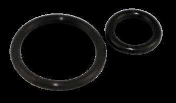
E-18
CORE DIAMETER SEAL COOLING PRODUCTS R R G L L R G Core OD L OD G Drill Line Diameter L R G Shoulder Groove ID Core OD1 (Max) Core OD2 Head Groove OD
O-RINGS
DASH NUMBER CROSS SECTION G L R -014 through -048 1/16 .093 to .098 .048 to .049 .005 to .015 -114 through -157 3/32 .140 to .145 .079 to .080 .005 to .015 -208 through -247 1/8 .187 to .192 .109 to .110 .005 to .015
NOMINAL CORE DIAMETER 1/16 CROSS SECTION 3/32 CROSS SECTION 1/8 CROSS SECTION DASH NUMBER CORE OD +.000 - .001 DASH NUMBER CORE OD +.000 - .001 DASH NUMBER CORE OD +.000 - .001 5/8 -014 0.623 - - -11/16 -015 0.685 - - -3/4 -016 0.748 - - -13/16 -017 0.81 -114 0.81 -7/8 -018 0.873 -115 0.873 -208 0.872 15/16 -019 0.935 -116 0.935 -209 0.934 1 -020 0.998 -117 0.998 -210 0.997 1-1/16 -021 1.06 -118 1.06 -211 1.059 1-1/8 -022 1.123 -119 1.123 -212 1.122 1-3/16 -023 1.185 -120 1.185 -213 1.184 1-1/4 -024 1.248 -121 1.248 -214 1.247 1-5/16 -025 1.31 -122 1.31 -215 1.309 1-3/8 -026 1.373 -123 1.373 -216 1.372 1-7/16 -027 1.435 -124 1.435 -217 1.434 1-1/2 -028 1.498 -125 1.498 -218 1.497 1-9/16 - - -126 1.56 -219 1.559 1-5/8 -029 1.623 -127 1.623 -220 1.622 1-11/16 - - -128 1.685 -221 1.684 1-3/4 -030 1.748 -129 1.748 -222 1.747 1-13/16 - - -130 1.81 -1-7/8 -031 1.873 -131 1.873 -223 1.872 1-15/16 - - -132 1.935 -2 -032 1.998 -133 1.998 -224 1.997 2-1/16 - - -134 2.06 -2-1/8 -033 2.123 -135 2.123 -225 2.122 2-3/16 - - -136 2.185 -2-1/4 -034 2.248 -137 2.248 -226 2.247 2-5/16 - - -138 2.31 -2-3/8 -035 2.373 -139 2.373 -227 2.372 2-7/16 - - -140 2.435 -2-1/2 -036 2.498 -141 2.498 -228 2.497 2-9/16 - - -142 2.56 -2-5/8 -037 2.623 -143 2.623 -229 2.622 2-11/16 - - -144 2.685 -2-3/4 -038 2.748 -145 2.748 -230 2.747 2-13/16 - - -146 2.81 -2-7/8 -039 2.873 -147 2.873 -231 2.872 2-15/16 - - -148 2.935 -3 -040 2.998 -149 2.998 -232 2.997 3-1/16 - - -150 3.06 -3-1/8 -041 3.123 -151 3.185 -233 3.122 3-1/4 - - - - -234 3.247 3-3/8 -042 3.373 - - -235 3.372 3-7/16 - - -152 3.435 -236 3.497 3-5/8 -043 3.623 - - -237 3.622 3-11/16 - - -153 3.685 -3-3/4 - - - - -238 3.747 3-7/8 -044 3.873 - - -239 3.872 3-15/16 - - -154 3.935 -4 - - - - -240 3.997 4-1/8 -045 4.123 - - -241 4.122 4-3/16 - - -155 4.185 -4-1/4 - - - - -242 4.247 4-3/8 -046 4.373 - - -243 4.372 4-7/16 - - -156 4.435 -4-1/2 - - - - -244 4.497 4-5/8 -047 4.623 - - -245 4.622 4-11/16 - - -157 4.685 -4-3/4 - - - - -246 4.747 4-7/8 -048 4.873 - - -247 4.872
CAD insertion point
APPLICATION GUIDELINES
• The Shoulder Groove ID is to be determined by the ID of the O-Ring and groove width.
• The corresponding Head Groove OD is to be determined by the OD of the O-Ring and groove width.
• Buna-N temp range: -20°F to 225°F (-28°C to 107°C)
• Viton® temp range: 0°F to 400°F (-17°C to 204°C)
To Order:
• Buna-N O-Rings: Specify the prefix “OR” before the dash number. Ex. OR-127 or OR-241.
• Viton O-Rings: Specify the prefix “OR” before the dash number and “-V” as the suffix. Ex. OR-127-V or OR-241-V.
• Minimum order quantity is 25 rings per size and must be purchased in increments of 25.
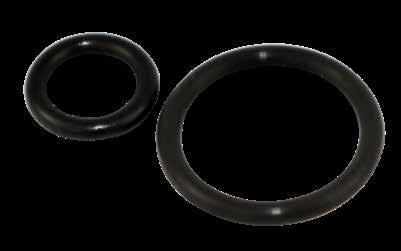
COOLING PRODUCTS E-19
L R G Shoulder Groove ID Core OD1 (Max) Core OD2 Head Groove OD DASH NUMBER CROSS SECTION G GROOVE WIDTH L R -025 through -046 1/16 .101 to .107 .050 to .054 .005 to .015 -123 through -157 3/32 .136 to .142 .074 to .080 .005 to .015 -217 through -245 1/8 .177 to .187 .101 to .107 .005 to .015
Seal Dimensions 1/16 CROSS SECTION 3/32 CROSS SECTION 1/8 CROSS SECTION CORE OD1 SHOULDER CORE OD2 HEAD SHOULDER CORE OD2 HEAD SHOULDER CORE OD2 HEAD DASH NUMBER GROOVE ID DASH NUMBER GROOVE OD DASH NUMBER GROOVE ID DASH NUMBER GROOVE OD DASH NUMBER GROOVE ID DASH NUMBER GROOVE OD 1 -025 1.176 1-5/8 -033 2.129 -123 1.174 1-11/16 -136 2.193 -217 1.171 1-3/4 -1-1/16 -026 1.239 1-11/16 -033 2.129 -124 1.237 1-3/4 -137 2.256 -218 1.234 1-13/16 -227 2.387 1-1/8 -027 1.301 1-3/4 -034 2.254 -125 1.299 1-13/16 -138 2.318 -219 1.296 1-7/8 -1-3/16 -028 1.364 1-13/16 -034 2.254 -126 1.362 1-7/8 -139 2.381 -220 1.359 1-15/16 -228 2.512 1-1/4 - - 1-7/8 - - -127 1.424 1-15/16 -140 2.443 -221 1.421 2 -1-5/16 -029 1.489 1-15/16 -035 2.379 -128 1.487 2 -141 2.506 -222 1.484 2-1/16 -229 2.637 1-3/8 - - 2 - - -129 1.549 2-1/16 -142 2.568 - - 2-1/8 -1-7/16 -030 1.614 2-1/16 -036 2.504 -130 1.612 2-1/8 -143 2.631 -223 1.609 2-3/16 -230 2.762 1-1/2 - - 2-1/8 - - -131 1.674 2-3/16 -144 2.693 - - 2-1/4 -1-9/16 -031 1.739 2-3/16 -037 2.629 -132 1.737 2-1/4 -145 2.756 -224 1.734 2-5/16 -231 2.887 1-5/8 - - 2-1/4 - - -133 1.799 2-5/16 -146 2.818 - - 2-3/8 -1-11/16 -032 1.864 2-5/16 -038 2.754 -134 1.862 2-3/8 - - -225 1.859 2-7/16 -232 3.012 1-3/4 - - 2-3/8 - - -135 1.924 2-7/16 -148 2.943 - - 2-1/2 -1-13/16 -033 1.989 2-7/16 -039 2.879 -136 1.987 2-1/2 -149 3.006 -226 1.984 2-9/16 -233 3.137 1-7/8 - - 2-1/2 - - -137 2.049 2-9/16 -150 3.068 - - 2-5/8 -1-15/16 -034 2.114 2-9/16 -040 3.004 -138 2.112 2-5/8 - - -227 2.109 2-11/16 -234 3.262 2 - - 2-5/8 - -139 2.174 2-11/16 -151 3.193 - - 2-3/4 -2-1/16 -035 2.239 2-11/16 -041 3.129 -140 2.237 2-3/4 - - -228 2.234 2-13/16 -235 3.387 2-1/8 - - 2-3/4 - - -141 2.299 2-13/16 - - - - 2-7/8 -2-3/16 -036 2.364 2-13/16 - - -142 2.362 2-7/8 - - -229 2.359 2-15/16 -236 3.512 2-1/4 - - 2-7/8 - - -143 2.424 2-15/16 -152 3.443 - - 3 -2-5/16 -037 2.489 2-15/16 -042 3.379 -144 2.487 3 - - -230 2.484 3-1/16 -237 3.637 2-3/8 - - 3 - - -145 2.549 3-1/16 - - - - 3-1/8 -2-7/16 -038 2.614 3-1/16 - - -146 2.612 3-1/8 -153 3.693 -231 2.609 3-3/16 -238 3.762 2-1/2 - - 3-1/8 - - -147 2.674 3-3/16 - - - - 3-1/4 -2-9/16 -039 2.739 3-3/16 -043 3.629 -148 2.737 3-1/4 - - -232 2.734 3-5/16 -239 3.887 2-5/8 - - 3-1/4 - - -149 2.799 3-5/16 - - - - 3-3/8 -2-11/16 -040 2.864 3-5/16 - - -150 2.862 3-3/8 - - -233 2.859 3-7/16 -240 4.012 2-3/4 - - 3-3/8 - - -151 2.924 3-7/16 -154 3.943 - - 3-1/2 -2-13/16 -041 2.989 3-7/16 -044 3.879 - - 3-1/2 - - -234 2.984 3-9/16 -241 4.137 2-15/16 - - 3-9/16 - - - - 3-5/8 - - -235 3.109 3-11/16 -242 4.262 3 - - 3-5/8 - - - - 3-11/16 -155 4.193 - - 3-3/4 -3-1/16 -042 3.239 3-11/16 -045 4.129 -152 3.237 3-3/4 -156 4.443 -236 3.234 3-13/16 -243 4.387 3-3/16 - - 3-13/16 - - - - 3-7/8 - - -237 3.359 3-15/16 -244 4.512 3-5/16 -043 3.489 3-15/16 -046 4.379 -153 3.487 4 -157 4.693 -238 3.484 4-1/16 -245 4.637
O-RINGS CORE FACE SEAL
Face
CAD insertion point
APPLICATION GUIDELINES
• Standard Plugs are flush type, 7/8” taper per foot. Oversize Plugs available with 3/4” taper per foot.

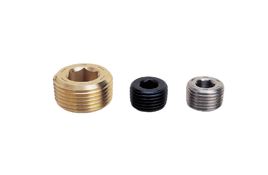
• To order oversized Pipe Plugs, add a “-O” to the end of the catalog number. Ex. BR50-O. Note: Oversized not available in 2” Brass.
APPLICATION GUIDELINES
• Fits BSPT and BSPP threads.
• Identification ring present on bottom of plugs.
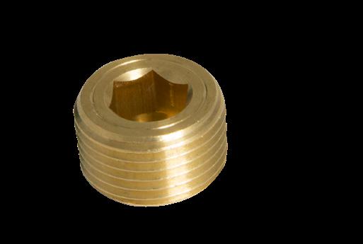
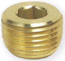
COOLING PRODUCTS E-20 Height Height PIPE THREAD NPT BRASS CATALOG NUMBER STEEL CATALOG NUMBER STAINLESS CATALOG NUMBER FLUSH HEIGHT OVERSIZE HEIGHT 1/16 BR06 ST06 SS06 .25 .31 1/8 BR12 ST12 SS12 .25 .31 1/4 BR25 ST25 SS25 .40 .43 3/8 BR37 ST37 SS37 .40 .50 1/2 BR50 ST50 SS50 .53 .56 3/4 BR75 ST75 SS75 .53 .62 1 BR100 ST100 SS100 .65 .75 1-1/4 BR125 ST125 SS125 .65 .81 1-1/2 BR150 ST150 SS150 .65 .81 2 BR200 ST200 SS200 .65 .87 PIPE THREAD BRASS CATALOG NUMBER STEEL CATALOG NUMBER STAINLESS CATALOG NUMBER HEIGHT (MM) 1/16-28 BSPT BR06-BSP ST06-BSP SS06-BSP 7 1/8-28 BSPT BR12-BSP ST12-BSP SS12-BSP 8 1/4-19 BSPT BR25-BSP ST25-BSP SS25-BSP 10 3/8-19 BSPT BR37-BSP ST37-BSP SS37-BSP 10 1/2-14 BSPT BR50-BSP ST50-BSP SS50-BSP 10 3/4-14 BSPT BR75-BSP ST75-BSP SS75-BSP 13 1-11 BSPT BR100-BSP - - 14 1 1/4-11 BSPT BR125-BSP - - 16 PIPE THREAD NPT CATALOG NUMBER HEIGHT 1/16 BRHD06 .289 1/8 BRHD12 .312 1/4 BRHD25 .445 3/8 BRHD37 .513 1/2 BRHD50 .625 3/4 BRHD75 .625
NPT STANDARD-DEEP HEX
STANDARD M Brass,
M Brass, Alloy Steel, and Stainless Steel M Brass
BSPT
Alloy Steel, and Stainless Steel
ALTERNATIVE CONFIGURATIONS AVAILABLE
• Note: Standard Series Extension Plugs are shown on page E-22. Keyed Connect Extension Plugs are shown on page E-23.
• Stainless Steel Extension Plugs are also available. Specify “-SS” at the end of the catalog number. Ex. 252L5.5-SS or 353L4-SS
• Extension Plugs can be obtained made to BSPT specs. The threads are BSPT, and all other dimensions are inch nominal per the chart on page E-22. To order, specify “-BSP” at the end of the catalog number. Ex. 252L5.5-BSP
• ND ST-3 Thread Sealant can be applied to any Extension Plug. To order, specify “-ST” at the end of the catalog number. Ex. 252L5.5-ST or 252L5.5-SS-ST
• Extension Plugs can be ordered cut to length, in any quantity, as shown below. All Extension Plugs cut to length have sealant applied to the tapered end for convenience. To order, specify series and NPT prefix with required length. Ex. 352L6.53
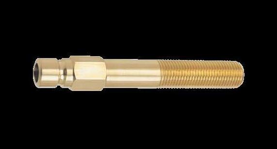

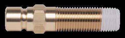
COOLING PRODUCTS E-21
H A L L 15⁄8 M Standard 3/4" per foot taper Series Length (Specify) M Standard 3/4" per foot taper with NDST-3 thread sealant applied W D B Overall Length M Standard N.P.T 3/32 Max. D = Clearance suggested for socket connector end wrench EXTENSION SERIES M PIPE THREAD D B W (REF) 250 1/16 .75 1.00 1/4 251 1/8 .87 1.25 5/16 252 1/4 1.00 1.50 7/16 253 3/8 1.12 1.50 9/16 350 1/16 1.00 1.25 1/4 351 1/8 1.00 1.25 5/16 352 1/4 1.00 1.50 7/16 353 3/8 1.12 1.50 9/16 354 1/2 1.50 1.75 11/16 553 3/8 1.37 1.62 9/16 554 1/2 1.50 1.75 11/16 H A L L 15⁄8 Standard 3/4" per foot taper Series Length (Specify) M Standard 3/4" per foot taper with NDST-3 thread sealant applied M S Standard 3/4" per foot taper with ND-ST3 thread sealant applied CAD insertion point
EXTENSION PLUGS
M Brass
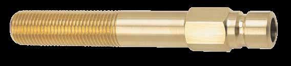
COOLING PRODUCTS E-22
1/4” HOLE
3/8” HOLE
1/2” HOLE CATALOG NUMBER L LENGTH M NPT H HEX SIZE A CATALOG NUMBER L LENGTH M NPT H HEX SIZE A CATALOG NUMBER L LENGTH M NPT H HEX SIZE A 1/16” PIPE EXTENSIONS 250L2.5 2.5 1/16 .37 .68 350L2.5 2.5 1/16 .56 .87 AVAILABLE ON REQUEST 250L4 4.0 1/16 .37 .81 350L4 4.0 1/16 .56 1.00 250L5.5 5.5 1/16 .37 .81 350L5.5 5.5 1/16 .56 1.00 250L7 7.0 1/16 .37 .81 350L7 7.0 1/16 .56 1.00 1/8” PIPE EXTENSIONS 251L2.5 2.5 1/8 .43 .68 351L2.5 2.5 1/8 .56 .87 AVAILABLE ON REQUEST 251L4 4.0 1/8 .43 1.00 351L4 4.0 1/8 .56 1.00 251L5.5 5.5 1/8 .43 1.00 351L5.5 5.5 1/8 .56 1.00 251L7 7.0 1/8 .43 1.00 351L7 7.0 1/8 .56 1.00 251L8.5 8.5 1/8 .43 1.00 351L8.5 8.5 1/8 .56 1.00 251L10 10.0 1/8 .43 1.00 351L10 10.0 1/8 .56 1.00 251L11.5 11.5 1/8 .43 1.00 351L11.5 11.5 1/8 .56 1.00 251L13 13.0 1/8 .43 1.00 351L13 13.0 1/8 .56 1.00 1/4” PIPE EXTENSIONS 252L2.5 2.5 1/4 .56 .87 352L2.5 2.5 1/4 .56 .87 AVAILABLE ON REQUEST 252L4 4.0 1/4 .56 1.25 352L4 4.0 1/4 .56 1.25 252L5.5 5.5 1/4 .56 1.25 352L5.5 5.5 1/4 .56 1.25 252L7 7.0 1/4 .56 1.25 352L7 7.0 1/4 .56 1.25 252L8.5 8.5 1/4 .56 1.25 352L8.5 8.5 1/4 .56 1.25 252L10 10.0 1/4 .56 1.25 352L10 10.0 1/4 .56 1.25 252L11.5 11.5 1/4 .56 1.25 352L11.5 11.5 1/4 .56 1.25 252L13 13.0 1/4 .56 1.25 352L13 13.0 1/4 .56 1.25 3/8” PIPE EXTENSIONS 253L2.5 2.5 3/8 .68 1.00 353L2.5 2.5 3/8 .68 1.00 553L2.5 2.5 3/8 .81 1.12 253L4 4.0 3/8 .68 1.25 353L4 4.0 3/8 .68 1.25 553L4 4.0 3/8 .81 1.37 253L5.5 5.5 3/8 .68 1.25 353L5.5 5.5 3/8 .68 1.25 553L5.5 5.5 3/8 .81 1.37 253L7 7.0 3/8 .68 1.25 353L7 7.0 3/8 .68 1.25 553L7 7.0 3/8 .81 1.37 253L8.5 8.5 3/8 .68 1.25 353L8.5 8.5 3/8 .68 1.25 553L8.5 8.5 3/8 .81 1.37 253L10 10.0 3/8 .68 1.25 353L10 10.0 3/8 .68 1.25 553L10 10.0 3/8 .81 1.37 253L11.5 11.5 3/8 .68 1.25 353L11.5 11.5 3/8 .68 1.25 553L11.5 11.5 3/8 .81 1.37 253L13 13.0 3/8 .68 1.25 353L13 13.0 3/8 .68 1.25 553L13 13.0 3/8 .81 1.37 1/2” PIPE
AVAILABLE ON REQUEST 354L2.5 2.5 1/2 .87 1.12 554L2.5 2.5 1/2 .87 1.12 354L4 4.0 1/2 .87 1.50 554L4 4.0 1/2 .87 1.50 354L5.5 5.5 1/2 .87 1.50 554L5.5 5.5 1/2 .87 1.50 354L7 7.0 1/2 .87 1.50 554L7 7.0 1/2 .87 1.50 354L8.5 8.5 1/2 .87 1.50 554L8.5 8.5 1/2 .87 1.50 354L10 10.0 1/2 .87 1.50 554L10 10.0 1/2 .87 1.50 354L11.5 11.5 1/2 .87 1.50 554L11.5 11.5 1/2 .87 1.50 354L13 13.0 1/2 .87 1.50 554L13 13.0 1/2 .87 1.50 • Use with standard Socket Connectors shown on page E-25 only.
EXTENSION PLUGS STANDARD SERIES 200 Series
300 Series
500 Series
EXTENSIONS
• Eliminate in/out connection mistakes, using the keyed plugs for all inlets
• Use with Keyed Socket Connectors shown on page E-27 only.
• Perfect for die cast jet cooling applications.
EXTENSION PLUGS KEYED CONNECT SERIES
EXTENSIONS (KEYED)

COOLING PRODUCTS E-23
1/4” HOLE
3/8” HOLE
1/2” HOLE CATALOG NUMBER L LENGTH M NPT H HEX SIZE A CATALOG NUMBER L LENGTH M NPT H HEX SIZE A CATALOG NUMBER L LENGTH M NPT H HEX SIZE A 1/16” PIPE EXTENSIONS (KEYED) 250L2.5-K 2.5 1/16 .37 .68 350L2.5-K 2.5 1/16 .56 .87 AVAILABLE ON REQUEST 250L4-K 4.0 1/16 .37 .81 350L4-K 4.0 1/16 .56 1.00 250L5.5-K 5.5 1/16 .37 .81 350L5.5-K 5.5 1/16 .56 1.00 250L7-K 7.0 1/16 .37 .81 350L7-K 7.0 1/16 .56 1.00 1/8” PIPE EXTENSIONS (KEYED) 251L2.5-K 2.5 1/8 .43 .68 351L2.5-K 2.5 1/8 .56 .87 AVAILABLE ON REQUEST 251L4-K 4.0 1/8 .43 1.00 351L4-K 4.0 1/8 .56 1.00 251L5.5-K 5.5 1/8 .43 1.00 351L5.5-K 5.5 1/8 .56 1.00 251L7-K 7.0 1/8 .43 1.00 351L7-K 7.0 1/8 .56 1.00 251L8.5-K 8.5 1/8 .43 1.00 351L8.5-K 8.5 1/8 .56 1.00 251L10-K 10.0 1/8 .43 1.00 351L10-K 10.0 1/8 .56 1.00 251L11.5-K 11.5 1/8 .43 1.00 351L11.5-K 11.5 1/8 .56 1.00 251L13-K 13.0 1/8 .43 1.00 351L13-K 13.0 1/8 .56 1.00 1/4” PIPE
252L2.5-K 2.5 1/4 .56 .87 352L2.5-K 2.5 1/4 .56 .87 AVAILABLE ON REQUEST 252L4-K 4.0 1/4 .56 1.25 352L4-K 4.0 1/4 .56 1.25 252L5.5-K 5.5 1/4 .56 1.25 352L5.5-K 5.5 1/4 .56 1.25 252L7-K 7.0 1/4 .56 1.25 352L7-K 7.0 1/4 .56 1.25 252L8.5-K 8.5 1/4 .56 1.25 352L8.5-K 8.5 1/4 .56 1.25 252L10-K 10.0 1/4 .56 1.25 352L10-K 10.0 1/4 .56 1.25 252L11.5-K 11.5 1/4 .56 1.25 352L11.5-K 11.5 1/4 .56 1.25 252L13-K 13.0 1/4 .56 1.25 352L13-K 13.0 1/4 .56 1.25 3/8” PIPE EXTENSIONS (KEYED) 253L2.5-K 2.5 3/8 .68 1.00 353L2.5-K 2.5 3/8 .68 1.00 553L2.5-K 2.5 3/8 .81 1.12 253L4-K 4.0 3/8 .68 1.25 353L4-K 4.0 3/8 .68 1.25 553L4-K 4.0 3/8 .81 1.37 253L5.5-K 5.5 3/8 .68 1.25 353L5.5-K 5.5 3/8 .68 1.25 553L5.5-K 5.5 3/8 .81 1.37 253L7-K 7.0 3/8 .68 1.25 353L7-K 7.0 3/8 .68 1.25 553L7-K 7.0 3/8 .81 1.37 253L8.5-K 8.5 3/8 .68 1.25 353L8.5-K 8.5 3/8 .68 1.25 553L8.5-K 8.5 3/8 .81 1.37 253L10-K 10.0 3/8 .68 1.25 353L10-K 10.0 3/8 .68 1.25 553L10-K 10.0 3/8 .81 1.37 253L11.5-K 11.5 3/8 .68 1.25 353L11.5-K 11.5 3/8 .68 1.25 553L11.5-K 11.5 3/8 .81 1.37 253L13-K 13.0 3/8 .68 1.25 353L13-K 13.0 3/8 .68 1.25 553L13-K 13.0 3/8 .81 1.37 1/2” PIPE
AVAILABLE ON REQUEST 354L2.5-K 2.5 1/2 .87 1.12 554L2.5-K 2.5 1/2 .87 1.12 354L4-K 4.0 1/2 .87 1.50 554L4-K 4.0 1/2 .87 1.50 354L5.5-K 5.5 1/2 .87 1.50 554L5.5-K 5.5 1/2 .87 1.50 354L7-K 7.0 1/2 .87 1.50 554L7-K 7.0 1/2 .87 1.50 354L8.5-K 8.5 1/2 .87 1.50 554L8.5-K 8.5 1/2 .87 1.50 354L10-K 10.0 1/2 .87 1.50 554L10-K 10.0 1/2 .87 1.50 354L11.5-K 11.5 1/2 .87 1.50 554L11.5-K 11.5 1/2 .87 1.50 354L13-K 13.0 1/2 .87 1.50 554L13-K 13.0 1/2 .87 1.50
200 Series
300 Series
500 Series
EXTENSIONS (KEYED)
CONNECTOR PLUGS STANDARD SERIES
Note: Use with Standard Series Socket Connectors sold on opposite page only.
TYPE: BSPT
Note: Use with Metric or Inch threaded Standard Series Socket Connectors sold on opposite page only. Also, each BSPT connector is marked with an identification ring near the hex.
ALTERNATIVE CONFIGURATIONS AVAILABLE
• For Connector Plugs manufactured from stainless steel, add “-SS” to the end of the catalog number. Ex. 250-SS or 351-SS or 251-FSS
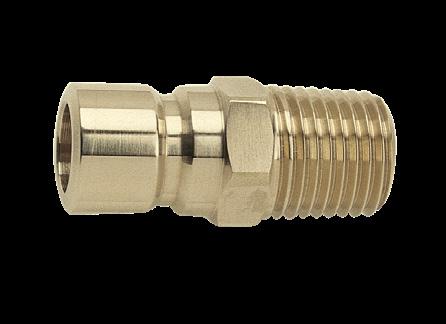
Note: 552F, 556F, and 252-M10 are available in brass only.
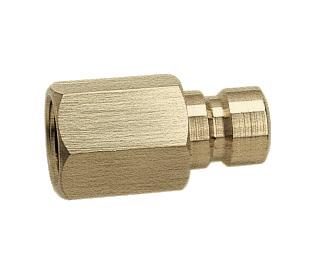
COOLING PRODUCTS E-24
L B D M L Pipe Nipple Inch Standard International Standard MALE TYPE: INCH FEMALE TYPE: INCH CATALOG NUMBER M NPT INNER DIAMETER D B L CATALOG NUMBER M NPT INNER DIAMETER L 200 SERIES (1/4” HOLE) 250 1/16 3/16 .75 .75 .94 250F 1/16 1/4 .75 251 1/8 1/4 .87 .75 .94 251F 1/8 1/4 1.00 252 1/4 1/4 1.00 .94 1.13 252F 1/4 1/4 1.25 253 3/8 1/4 1.12 .94 1.19 253F 3/8 1/4 1.16 300 SERIES (3/8” HOLE) 351 1/8 1/4 1.00 1.00 1.20 351F 1/8 11/32 1.00 352 1/4 3/8 1.00 1.09 1.34 352F 1/4 3/8 1.34 353 3/8 3/8 1.12 1.13 1.38 353F 3/8 3/8 1.34 354 1/2 3/8 1.50 1.25 1.59 354F 1/2 3/8 1.57 500 SERIES (1/2” HOLE) 552 1/4 3/8 1.37 1.37 1.62 552F 1/4 7/16 1.25 553 3/8 1/2 1.37 1.37 1.62 553F 3/8 9/16 1.37 554 1/2 5/8 1.50 1.50 1.75 554F 1/2 5/8 1.75 556 3/4 5/8 1.75 1.56 1.90 556F 3/4 5/8 1.75 MALE TYPE: BSPT or METRIC
CATALOG NUMBER M BSPT INNER DIAMETER D B L HEX INCH CATALOG NUMBER M BSPT INNER DIAMETER L HEX INCH 200 SERIES (6.35MM HOLE) 251-BSPT 1/8 6.4 22 19 24 7/16 251F-BSPT 1/8 6 25 1/2 252-BSPT 1/4 6.4 25 24 29 9/16 252F-BSPT 1/4 6 32 5/8 252-M10 M10 6.4 25 24 29 9/16 300 SERIES (9.52MM HOLE) 351-BSPT 1/8 9.5 25 25 30 9/16 351F-BSPT 1/8 9 25 9/16 352-BSPT 1/4 9.5 25 28 34 9/16 352F-BSPT 1/4 9 34 9/16 353-BSPT 3/8 9.5 28 29 35 11/16 353F-BSPT 3/8 9 34 3/4 500 SERIES (12.7MM HOLE) 553-BSPT 3/8 12.7 35 35 41 13/16 553F-BSPT 3/8 15 35 13/16 554-BSPT 1/2 15.8 38 38 44 7/8 554F-BSPT 1/2 15 44 1/2
FEMALE
M Brass M Brass M Brass M Brass
• Pressure to 200 psi
• Max temp = 400°F
• Use with standard Connector Plugs sold on opposite page or Extension Plugs sold on page E-22.
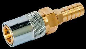
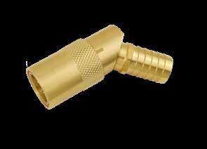
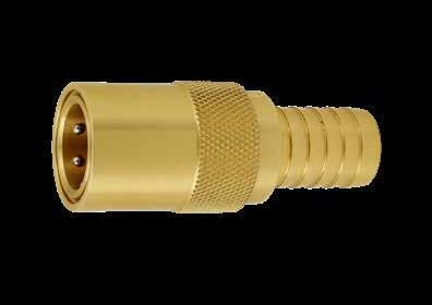
SOCKET CONNECTORS
M Brass with Stainless Steel Bearings and Silicone Seals
ALTERNATIVE CONFIGURATIONS AVAILABLE
• To order valved style Socket Connectors or Bodies (shown at right), add “-V” to the end of the catalog number. Ex. SC316-V
• To order Socket Connectors or Bodies with barbs for Push-Lok® hose, specify “-PL” at the end of the catalog number. Ex. SC326-PL or SC306-V-PL
• Note: Valved versions (-V or -V-PL) are not available in the 500 series.
STANDARD SERIES: LOCKING CONNECTORS
This system provides a positive locking connection to Extension or Connector Plugs. Connect and twist to lock the sleeve into place.
To Order:
• Specify “-L” as the suffix to the standard items in the chart above. Examples:
SC205-L (Standard Barbs)
SC300B-L (Body)
SC326-PL-L (Push-Lok Barbs)
Note: Not available in the Valved versions.
COOLING PRODUCTS E-25
Hole Largest Diameter 200 SERIES (1/4” HOLE) 300 SERIES (3/8” HOLE) 500 SERIES (1/2” Hole) CATALOG NUMBER HOSE ID LARGEST DIA. CATALOG NUMBER HOSE ID LARGEST DIA. CATALOG NUMBER HOSE ID LARGEST DIA. S T R A I G H T SC204 1/4 .71 SC306 3/8 .97 SC504 1/2 1.21 SC205 5/16 .71 SC308 1/2 .97 SC506 3/4 1.21 SC206 3/8 .71 - - - - -90˚ S T E M SC214 1/4 .71 SC316 3/8 .97 SC514 1/2 1.21 SC215 5/16 .71 SC318 1/2 .97 SC516 3/4 1.21 SC216 3/8 .71 - - - - -45˚ S T E M SC224 1/4 .71 SC326 3/8 .97 SC524 1/2 1.21 SC225 5/16 .71 SC328 1/2 .97 SC526 3/4 1.21 SC226 3/8 .71 - - - - -Socket Body Only CATALOG NUMBER THREAD CATALOG NUMBER THREAD CATALOG NUMBER THREAD SC200B 1/8 SC300B 1/4 SC500B 1/2 SC200B-4 1/4 SC300B-4 3/8 -SC200B-90 1/4 SC300B-90 3/8 SC500B-90 1/2 Replacement Seals: Silicone (Red) SC200S SC300S SC500S Replacement Seals: Viton (Black) SC200S-V SC300S-V SC500S-V
Patent Pending. Straight 90° Degree
CONNECTOR PLUGS KEYED CONNECT SERIES
APPLICATION GUIDELINES
• Eliminate in/out connection mistakes, using the keyed plugs for all inlets.
• Enables faster changeover.
• Use with Keyed Socket Connectors as shown on opposite page only.
ALTERNATIVE CONFIGURATIONS AVAILABLE
• For Connector Plugs manufactured from stainless steel, add “-SS” to the end of the catalog number. Ex. 250-K-SS or 351F-K-SS
Note: The 250F-K, 351F-K and all 500 Series Female Plugs are available in brass only.
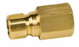
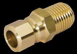
• Contact Customer Service for metric options.
• Keyed connectors do not fit standard Socket connectors.
COOLING PRODUCTS E-26
L B D M Keyed for identification L Pipe Nipple Keyed for identification Male Type: Inch Standard Female Type: Inch Standard 200 SERIES (1/4” HOLE) 300 SERIES (3/8” HOLE) 500 SERIES (1/2” HOLE) CATALOG NUMBER M NPT INNER DIAMETER D B L CATALOG NUMBER M NPT INNER DIAMETER D B L CATALOG NUMBER M NPT INNER DIAMETER D B L 250-K 1/16 3/16 .75 .75 .94 351-K 1/8 1/4 1.00 1.00 1.20 552-K 1/4 3/8 1.37 1.37 1.62 251-K 1/8 1/4 .87 .75 .94 352-K 1/4 3/8 1.00 1.09 1.34 553-K 3/8 1/2 1.37 1.37 1.62 252-K 1/4 1/4 1.00 .94 1.13 353-K 3/8 3/8 1.12 1.13 1.38 554-K 1/2 5/8 1.50 1.50 1.75 253-K 3/8 1/4 1.12 .94 1.19 354-K 1/2 3/8 1.50 1.25 1.59 556-K 3/4 5/8 1.75 1.56 1.90 200 SERIES (1/4” HOLE) 300 SERIES (3/8” HOLE) 500 SERIES (1/2” HOLE) CATALOG NUMBER M NPT INNER DIAMETER L CATALOG NUMBER M NPT INNER DIAMETER L CATALOG NUMBER M NPT INNER DIAMETER L 250F-K 1/16 1/4 1.00 351F-K 1/8 11/32 1.00 552F-K 1/4 7/16 1.25 251F-K 1/8 1/4 1.00 352F-K 1/4 3/8 1.00 553F-K 3/8 9/16 1.37 252F-K 1/4 1/4 1.25 353F-K 3/8 3/8 1.62 554F-K 1/2 5/8 1.75 253F-K 3/8 1/4 1.38 354F-K 1/2 3/8 1.75 556F-K 3/4 5/8 1.75 M Brass M Brass
SOCKET CONNECTORS KEYED CONNECT SERIES
APPLICATION GUIDELINES
• Eliminate in/out connection mistakes, using the keyed plugs for all inlets
• Enables faster changeovers
• Pressure to 200 psi
• Max temp = 400°F
• Includes Blue Safety Clip

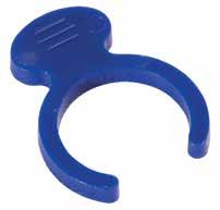
• Use with Keyed Connector Plugs sold on opposite page or Keyed Extension Plugs shown on page E-23.
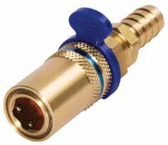
Inside is keyed to accept Keyed Connect Extension and Connector Plugs
M Brass with Stainless Steel Bearings and Silicone Seals
Note: 200 and 300 Series Straight Socket Connectors are manufactured from a single piece, not assembled as shown.
ALTERNATIVE CONFIGURATIONS AVAILABLE
• To order Socket Connectors or Bodies with barbs for Push-Lok® hose, specify “-PL” before the -K within the catalog number. Ex. SC326-PL-K or SC306-PL-K
APPLICATION GUIDELINES
• Clips are designed for the Keyed Connect Series of Socket Connectors. They can be used on the standard or locking Socket Connectors but will be for color designation only.
SAFETY CLIPS
COOLING PRODUCTS E-27
Hole Thread Largest Diameter
200 SERIES (1/4” HOLE) 300 SERIES (3/8” HOLE) 500 SERIES (1/2” HOLE) CATALOG NUMBER HOSE ID LARGEST DIA. CATALOG NUMBER HOSE ID LARGEST DIA. CATALOG NUMBER HOSE ID LARGEST DIA. SC204-K 1/4 .71 SC306-K 3/8 .97 SC504-K 1/2 1.21 SC205-K 5/16 .71 SC308-K 1/2 .97 SC506-K 3/4 1.21 SC206-K 3/8 .71 - - - - -SC214-K 1/4 .71 SC316-K 3/8 .97 SC514-K 1/2 1.21 SC215-K 5/16 .71 SC318-K 1/2 .97 SC516-K 3/4 1.21 SC216-K 3/8 .71 - - - - -SC224-K 1/4 .71 SC326-K 3/8 .97 SC524-K 1/2 1.21 SC225-K 5/16 .71 SC328-K 1/2 .97 SC526-K 3/4 1.21 SC226-K 3/8 .71 - - - - -CATALOG NUMBER THREAD CATALOG NUMBER THREAD CATALOG NUMBER THREAD SC200B-K 1/8 SC300B-K 1/4 SC500B-K 1/2 SC200B-4-K 1/4 SC300B-4-K 3/8 -Replacement Seals: Silicone (Red) SC200S SC300S SC500S Replacement Seals: Viton (Black) SC200S-V SC300S-V SC500S-V S T R A I G H T 90˚ S T E M 45˚ S T E M
CATALOG NUMBER COLOR SERIES SC200-BL Blue 200 SC300-BL 300 SC500-BL 500 SC200-R Red 200 SC300-R 300 SC500-R 500
ADJUSTABLE HEX NIPPLES
To Order:
• Specify prefix and length. Ex APN50L11.5.
ALTERNATIVE CONFIGURATIONS AVAILABLE
• For Adjustable Hex Nipples manufactured from stainless steel, add “-SS” to the end of the catalog number. Ex. APN25L7-SS or APN50L4-SS
• Adjustable Hex Nipples can be ordered cut to any length, in any quantity. Specify the catalog number (for brass or stainless steel) with required length. Ex. APN25L6.25 or APN37L5.75-SS
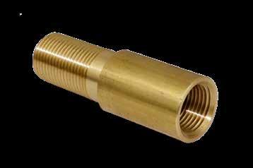
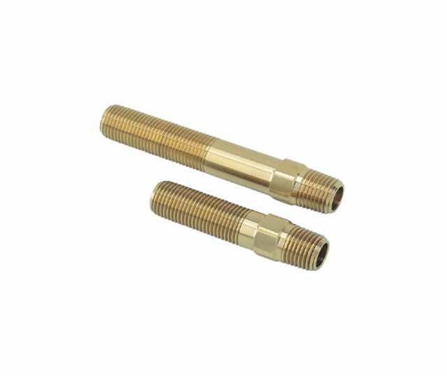
HEX KEY EXTENSION PIPES
To Order:
• Specify prefix and length. Ex. HKEPN12L2.5
ALTERNATIVE CONFIGURATIONS AVAILABLE
• Hex Key Extension Pipes can be ordered cut to any length in any quantity. Specify the catalog prefix with required length. Ex. HKEPN25L6.25
E-28
COOLING PRODUCTS
CATALOG NUMBER M PIPE NPT A D H AVAILABLE OVERALL LENGTHS (L) 2.5 4 5.5 7 8.5 HKEPN12 1/8 .75 .50 1/4 • • • • • HKEPN25 1/4 1.00 .69 3/8 • • • • • HKEPN37 3/8 1.25 .81 1/2 • • • • • HKEPN50 1/2 1.50 1.00 9/16 • • • • • CATALOG NUMBER M PIPE NPT A H AVAILABLE OVERALL LENGTHS (L) 2.5 4 5.5 7 8.5 10 11.5 13 APN06 1/16 .68 3/8 • • • • • • • • APN12 1/8 .75 7/16 • • • • • • • • APN25 1/4 .87 9/16 • • • • • • • • APN37 3/8 1.00 11/16 • • • • • • • • APN50 1/2 1.37 7/8 • • • • • • • • M M A L H 15⁄8 CAD insertion point M M M A L H D 15⁄8 CAD insertion point
M Brass
M Brass
HEX KEY ELBOWS
To Order:
• Specify Prefix and length. Ex. HKEE1818L2.5 or HKEE1414L11.5
• Hex Key Extension Elbows can be ordered in any length in any quantity. Specify the catalog prefix with the required length. Ex. HKEE1414L3.75
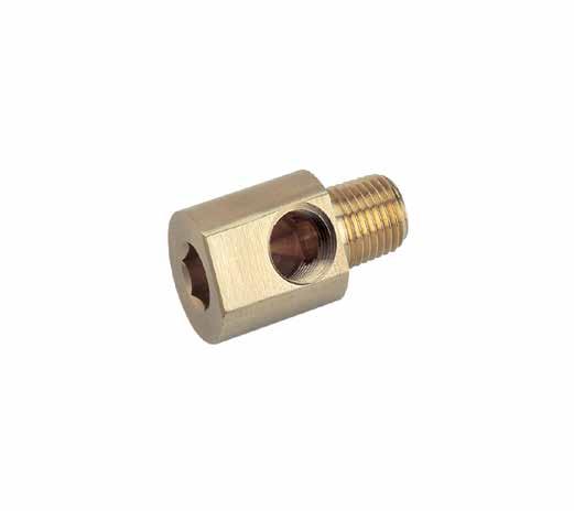
HEX KEY EXTENSION ELBOWS
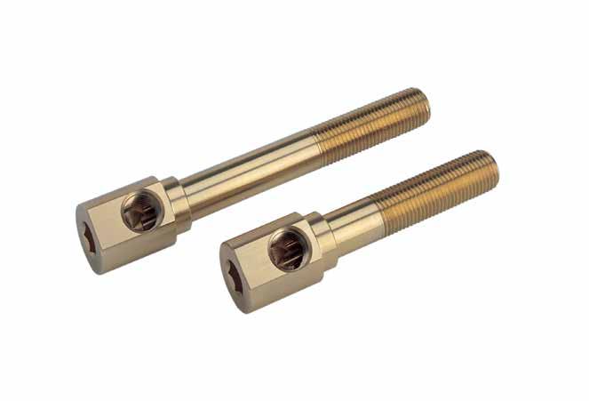
HEX KEY STREET ELBOWS
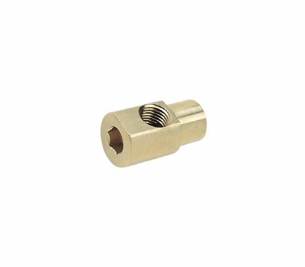
E-29
CATALOG NUMBER M PIPE NPT P NPT HEX KEY D E Available Overall Lengths (L) 2.5 4 5.5 7 8.5 10 11.5 13 HKEE1616 1/16 1/16 1/4 .552 .531 • • • • • • • • HKEE1818 1/8 1/8 5/16 .615 .580 • • • • • • • • HKEE1414 1/4 1/4 3/8 .860 .660 • • • • • • • • HKEE3838 3/8 3/8 1/2 .985 .780 • • • • • • • • HKEE1212 1/2 1/2 1/2 1.235 .940 • • • • • • • • CATALOG NUMBER M NPT P NPT HEX KEY L D E HKL1616 1/16 1/16 1/4 1.156 .552 .531 HKL1618 1/16 1/8 5/16 1.218 .615 .531 HKL1818 1/8 1/8 5/16 1.312 .615 .580 HKL1814 1/8 1/4 3/8 1.500 .860 .593 HKL1414 1/4 1/4 3/8 1.625 .860 .660 HKL1438 1/4 3/8 1/2 1.625 .985 .712 HKL3838 3/8 3/8 1/2 1.750 .985 .780 HKL1212 1/2 1/2 1/2 2.250 1.235 .940 M D P E L Hex Key E L M P Hex Key D CATALOG NUMBER M NPT P NPT HEX KEY L D E HK1616 1/16 1/16 1/4 1.12 .552 .531 HK1818 1/8 1/8 5/16 1.25 .615 .580 HK1814 1/8 1/4 3/8 1.375 .860 .593 HK1414 1/4 1/4 3/8 1.50 .860 .660 HK3838 3/8 3/8 1/2 1.75 .985 .780 HK1438 1/4 3/8 1/2 1.625 .985 .712 HK1212 1/2 1/2 1/2 2.12 1.235 .940 CAD insertion point CAD insertion point CAD insertion point Hex Key D E L P M 15⁄8 M Brass M Brass
M Brass
*Close is the shortest available nipple length.
To Order:
• Specify prefix and length. Ex. BPN37CLOSE or BPN12L3.5
• Pipe Nipples can be ordered cut to any length, in any quantity. To order, specify the prefix and required length. Ex. BPN37L5.25 or GPN12L2.25
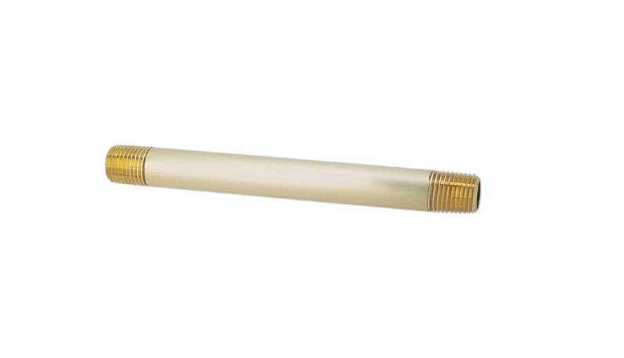
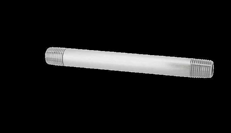
PUSH-LOK ® HOSE
M Synthetic Rubber Tube (Parker Series 801)
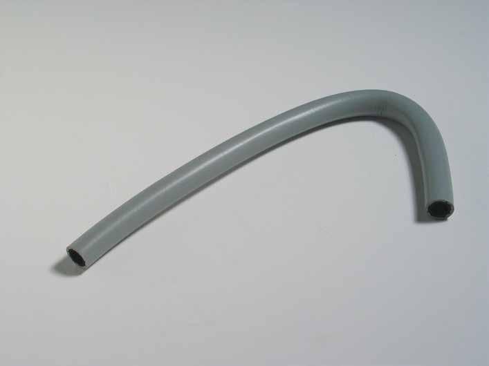
APPLICATION GUIDELINES
• Sold in 24” lengths.
• Max temperature with water: 190˚F (90˚C).
• Working pressure: 250 psi
• Burst pressure: 1000 psi
• Note: WJH31 is only available in Black (BA).
To Order:
• Specify catalog number with the appropriate color suffix: Gray (GR), Black (BA), Blue (BL), Green (G), Yellow (Y), and Red (R). Ex. WJH50-Y.
• For a 50’ box, specify “-B” after the color. Ex. WJH37-Y-B.
• Reels also available by contacting Customer Service.
E-30 CATALOG NUMBER HOSE I.D. HOSE O.D. MINIMUM BEND RADIUS (IN) INCHES OF MERCURY WJH25- 1/4 .50 2.5 28 WJH31-BA 5/16 .58 3 28 WJH37- 3/8 .63 3 28 WJH50- 1/2 .78 5 28 WJH62- 5/8 .91 6 15 WJH75- 3/4 1.03 7 15
AVAILABLE OVERALL LENGTHS (L) 3 3.5 4 4.5 5 5.5 6 7 8 9 10 11 12 • • • • • • • • • • • • • • • • • • • • • • • • • • BPN25 GPN25 1/4 7/8 • • • • • • • • • • • • • • • • • BPN37 GPN37 3/8 1 • • • • • • • • • • • • • • • • • BPN50 GPN50 1/2 1-1/8 • • • • • • • • • • • • • • • • •
APPLICATION GUIDELINES
• Water Blocker Plugs are used to divert the flow of water, and can be removed and reinstalled for maintenance purposes.
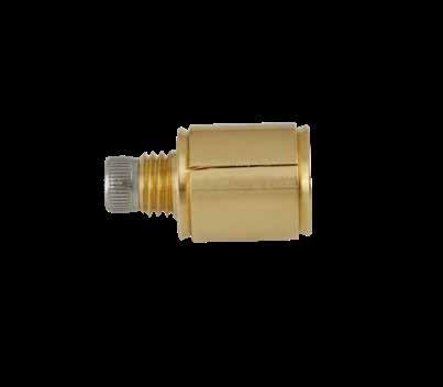
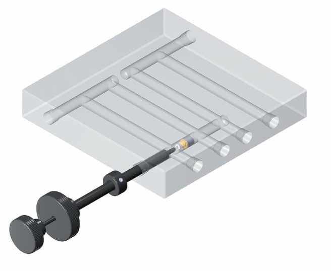
• Maximum Pressure: 175 PSI
• Wrench (sold below) is available in two different lengths on most sizes.
WATER BLOCKER
COOLING PRODUCTS E-31
Installation and Removal Handle Expansion Tool Handle Slide Collar PROGRESSIVE COMPONENTS W A T R REKCOLB HCNERW 6TNETAPSU 0 7 7 9 7 CATALOG NUMBER WATER BLOCKER OVERALL LENGTH WB25S24 WB250 24” WBS12 WB344-WB375 12” WBS24 WB344-WB375 24” WBL12 WB437-WB688 12” WBL24 WB437-WB688 24” CATALOG NUMBER D ±.005 B L WATERLINE NOMINAL WATERLINE DIAMETER WB250 .245 .36 .60 1/16 NPT .250 WB344 .334 .41 .71 1/8 NPT .344 WB344-75 .334 .79 1.094 1/8 NPT .344 WB375 .365 .41 .71 1/4 NPT .375 WB437 .428 .43 .78 1/4 NPT .437 WB562 .552 .57 .92 3/8 NPT .562 WB688 .678 .64 1.06 1/2 NPT .688 B D L
insertion point
CAD
M Brass with Stainless Steel Screw
WRENCHES
THREADLESS PLUGS
M Brass with Buna O-Rings
temp: 250°F (120°C)
ALTERNATIVE CONFIGURATIONS AVAILABLE
• For plugs with Viton O-rings (maximum temperature 400˚F, 200˚C) specify “-V” at the end of the catalog number. Ex. TWP500-V or OR-007-V for the O-ring.
• For stainless steel threadless plugs, specify “-SS” at the end of the catalog number. Ex. TWP500-SS or TWP281-SS-V for stainless plugs with Viton O-rings.
TAP-IN O-RING PLUGS
APPLICATION GUIDELINES
• Tap-In O-Ring Plugs do not require steel back up.
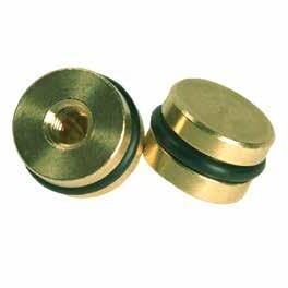
• Viton O-Rings included for maximum temperature of 400˚F (200˚C).
• Max pressure: 200 psi
M Brass with Viton O-Rings
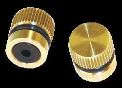
THREADLESS DIVERTING PLUGS
M Brass with Buna O-Rings
APPLICATION GUIDELINES
• Maximum pressure: 70 psi
ALTERNATIVE CONFIGURATIONS AVAILABLE
• For plugs with Viton O-rings (maximum temperature 400˚F, 200˚C) specify “-V” at the end of the catalog number. Ex. TDP50-V or TDP50-OS-V
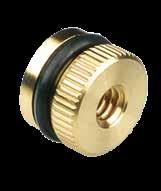
COOLING PRODUCTS E-32
PUSH-IN O-RING PLUGS L H D O-Ring D B 03 x 20° Break +.005 -.000 +.005 -.000
CATALOG NUMBER A B C O-RING D REAM DIA. E REPLACEMENT O-RING (BUNA) TWP281 .273 .250 1/16 .281 #6-32 OR-007 TWP375 .366 .312 1/16 .375 #10-32 OR-010 TWP500 .494 .312 1/16 .500 #10-32 OR-012 TWP625 .618 .437 3/32 .625 1/4-20 OR-111 TWP750 .743 .500 3/32 .750 1/4-20 OR-113 TWP1000 .990 .625 1/8 1.000 3/8-16 OR-117 TWP1187 1.177 .625 1/8 1.187 3/8-16 OR-120 CATALOG NUMBER NOMINAL PIPE SIZE D DRILL SIZE H L TDP12 1/8 11/32 5/64 .50 TDP12-OS 1/8 23/64 5/64 .50 TDP25 1/4 7/16 1/8 .56 TDP25-OS 1/4 29/64 1/8 .56 TDP37 3/8 9/16 1/8 .62 TDP37-OS 3/8 37/64 1/8 .62 TDP50 1/2 11/16 1/8 .62 TDP50-OS 1/2 45/64 1/8 .62 B +.000 -.005 E C A CATALOG NUMBER NOMINAL PIPE SIZE D REAM DIA. B DEPTH +.005 -.000 E TAP281 1/16 .281 .312 #6-32 TAP375 1/8 .375 .312 #10-32 TAP500 1/4 .500 .375 1/4-20 TAP625 3/8 .625 .437 5/16-18 TAP750 1/2 .750 .500 5/16-18 E D B ±.002 .03 x 20° Break
CAD insertion point
Threadless O-Ring Plugs are designed for inserts backed up by mold steel.
Maximum
ALTERNATIVE CONFIGURATIONS AVAILABLE
• Rods are available with BSP threads. To order, specify -BSP to the end of the catalog number. Ex. DR250-BSP.
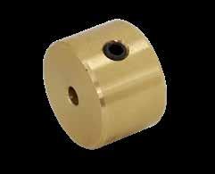
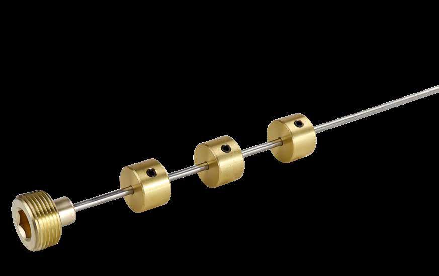
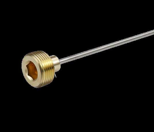
• Longer lengths and Diverting Rods cut to length are available. Contact Customer Service for pricing and delivery.
Includes locking screw.
E-33 CATALOG NUMBER PIPE SIZE NPT L D DIVERTER PLUGS USED DR125 1/8 12 3/32 D125 DR250 1/4 18 1/8 D250 DR375 3/8 18 1/8 D375 DR500 1/2 24 3/16 D500 DR750 3/4 24 3/16 D750 DR1000 1 36 3/16 D1000
CATALOG NUMBER FOR PIPE SIZE NPT FOR ROD DIAMETER D +.000 -.005 B D125 1/8 3/32 .340 3/8 D250 1/4 1/8 .432 7/16 D375 3/8 1/8 .557 1/2 D500 1/2 3/16 .682 3/4 D750 3/4 3/16 .932 3/4 D1000 1 3/16 1.115 3/4
M Brass with Stainless Steel Rod
L Plug (NPT) Rod Diameter D D B Positive positioning of Plugs Rod Diameter D D B CAD insertion point RODS
PLUGS
WATER JUMPERS
PUSH-LOK ® SERIES
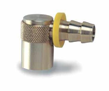
APPLICATION GUIDELINES
• Maximum temp: 400°F (200°C)
COOLING PRODUCTS E-34
Hose ID C L A M
Twist Lock Sleeve prevents accidental disconnect
Viton seals CAD insertion point CATALOG NUMBER FITS PLUG SERIES NUMBER HOSE I.D. L C M A WJ200-25 200 1/4 1 1-1/4 3/8 5/8 WJ200-37 200 3/8 1 1-1/4 3/8 5/8 WJ300-37 300 3/8 1-7/16 1-9/16 1/2 7/8 WJ300-50 300 1/2 1-7/16 1-9/16 1/2 7/8 WJ500-50 500 1/2 2-1/8 1-7/8 7/8 1-3/8 WJ500-75 500 3/4 2-1/8 2 7/8 1-3/8
Uses standard Push-Lok hose
M Brass and Stainless Steel
WATER JUMPERS SWIVEL TYPE
APPLICATION GUIDELINES
• Maximum temp: 400°F (200°C)
allows maximum torque during installation along with positive removal Recessed installation protects hose and fittings.
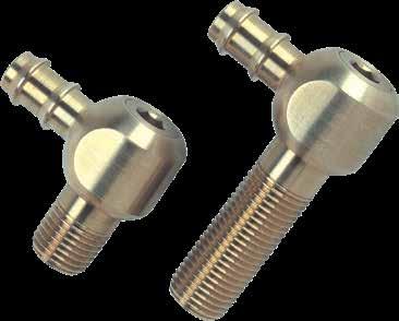
allows maximum torque during installation along with positive removal
Recessed installation protects hose and fittings.
COOLING PRODUCTS E-35
CATALOG NUMBER PIPE SIZE NPT HOSE I.D. HEX KEY SIZE L A C M D MIN. POCKET WIDTH MIN. POCKET DEPTH WJ125L1.1 1/8 5/16 3/16 1-3/16 11/16 1 5/8 .660 11/16 1 WJ125L2.0 1/8 5/16 3/16 2 11/16 1 5/8 .660 11/16 1 WJ125L3.5 1/8 5/16 3/16 3-1/2 11/16 1 5/8 .660 11/16 1 WJ250L1.4 1/4 3/8 1/4 1-7/16 13/16 1-3/16 25/32 .840 7/8 1-3/16 WJ250L2.3 1/4 3/8 1/4 2-3/8 13/16 1-3/16 25/32 .840 7/8 1-3/16 WJ250L3.8 1/4 3/8 1/4 3-7/8 13/16 1-3/16 25/32 .840 7/8 1-3/16 WJ375L1.6 3/8 1/2 5/16 1-5/8 1 1-3/8 15/16 .980 1 1-3/8 WJ375L2.6 3/8 1/2 5/16 2-5/8 1 1-3/8 15/16 .980 1 1-3/8 WJ375L4.1 3/8 1/2 5/16 4-1/8 1 1-3/8 15/16 .980 1 1-3/8 WJ500L2.0 1/2 3/4 3/8 2 1-1/8 1-1/2 1-1/8 1.235 1-1/4 1-9/16 WJ500L2.0-50 1/2 1/2 3/8 2 1-1/8 1-1/2 1-1/8 1.235 1-1/4 1-9/16 WJ500L3.0 1/2 3/4 3/8 3 1-1/8 1-1/2 1-1/8 1.235 1-1/4 1-9/16 WJ500L3.0-50 1/2 1/2 3/8 3 1-1/8 1-1/2 1-1/8 1.235 1-1/4 1-9/16 WJ500L4.5 1/2 3/4 3/8 4-1/2 1-1/8 1-1/2 1-1/8 1.235 1-1/4 1-9/16 WJ500L4.5-50 1/2 1/2 3/8 4-1/2 1-1/8 1-1/2 1-1/8 1.235 1-1/4 1-9/16 Hose ID C M L A D Uses
Push-Lok hose Hex
standard
Minimum Pocket Depth Minimum Pocket Width Hose ID C M L A D Uses
Push-Lok hose Hex
Minimum Pocket Depth Minimum Pocket Width
standard
CAD insertion point
M Brass with internal Viton seals
EXTENSION ELBOWS
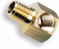

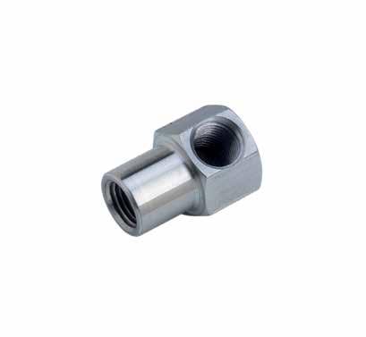
COOLING PRODUCTS E-36 CATALOG NUMBER M PIPE NPT P IN/OUT NPT HEX SIZE D E AVAILABLE OVERALL LENGTHS (L) 2.5 4 5.5 7 8.5 10 11.5 13 HELB1818 1/8 1/8 .75 1.25 .28 • • • • • • • • HELB1814 1/4 1/8 .75 1.25 .28 • • • • • • • • HELB1414 1/4 1/4 .87 1.37 .34 • • • • • • • • HELB1438 3/8 1/4 .875 1.37 .34 • • • • • • • • HELB3838 3/8 3/8 1.00 1.50 .50 • • • • • • • • HELB1212 1/2 1/2 1.25 1.75 .62 • • • • • • • • L D E P M L D E P M ALLOY STEEL CATALOG NUMBER BRASS CATALOG NUMBER M NPT P NPT HEX SIZE L D E HELS1616M HELB1616M 1/16 1/16 9/16 .81 1.00 .218 HELS1818M HELB1818M 1/8 1/8 3/4 1.06 1.25 .281 HELS1814M HELB1814M 1/4 1/8 3/4 1.06 1.25 .281 HELS1414M HELB1414M 1/4 1/4 7/8 1.31 1.37 .343 HELS1438M HELB1438M 3/8 1/4 7/8 1.31 1.37 .343 HELS3838M HELB3838M 3/8 3/8 1 1.62 1.50 .437 HELS1212M HELB1212M 1/2 1/2 1-1/4 2.00 1.87 .562 HELS7575M HELB7575M 3/4 3/4 1-1/2 2.12 2.25 .625 ALLOY STEEL CATALOG NUMBER BRASS CATALOG NUMBER M NPT P NPT HEX SIZE L D E HELS1616 HELB1616 1/16 1/16 9/16 .81 1.00 .218 HELS1818 HELB1818 1/8 1/8 3/4 1.00 1.25 .281 HELS1414 HELB1414 1/4 1/4 7/8 1.37 1.37 .343 HELS3838 HELB3838 3/8 3/8 1 1.62 1.50 .500 HELS1212 HELB1212 1/2 1/2 1-1/4 1.87 1.87 .562 HELS3434 HELB3434 3/4 3/4 1-1/2 2.25 2.25 .625 L D E P M CAD insertion point
CAD insertion point CAD insertion point MALE
M Brass
MALE
Specify prefix and length. Ex. HELB1818L2.5 or HELB1414L11.5
To Order: •
FITTINGS
Note: MB16 and MB18 include Buna O-rings and clamps.
MALE PUSH-LOK HOSE BARBS
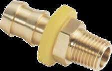
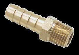
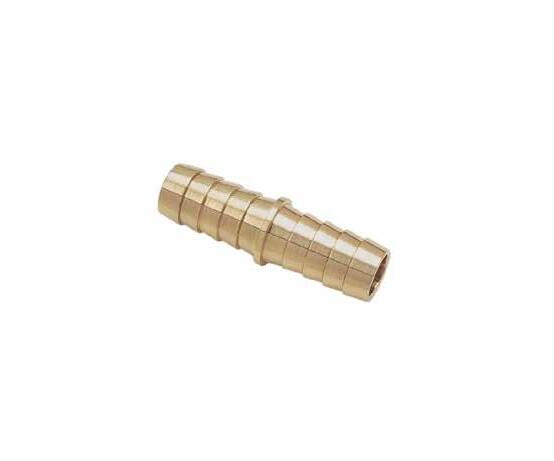
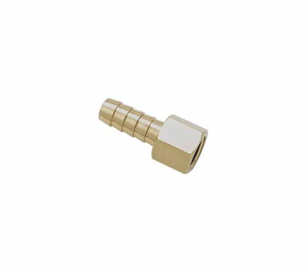
FEMALE HOSE BARBS
HOSE SPLICERS
COOLING PRODUCTS
D L A Hose I.D. D Hose I.D. L A
MALE HOSE BARBS
CATALOG NUMBER HOSE I.D. D A L HS14 1/4 .187 .97 2.00 HS38 3/8 .281 .97 2.00 HS50 1/2 .375 .97 2.00 CATALOG NUMBER M NPT HOSE I.D. D A L FB14-2 1/8 1/4 .187 .97 1.47 FB14-4 1/4 1/4 .187 .97 1.58 FB15-4 1/4 5/16 .250 .97 1.58 FB38-2 1/8 3/8 .281 .97 1.47 FB38-4 1/4 3/8 .281 .97 1.58 FB50-6 3/8 1/2 .375 .97 1.63 FB50-8 1/2 1/2 .375 .97 1.73 CATALOG NUMBER M NPT HOSE I.D. D A L MB16-0 #10-32 UNF 1/16 .052 .45 .57 MB18-0 #10-32 UNF 1/8 .090 .56 .81 MB18-2 1/8 1/8 .093 .50 1.03 MB14-2 1/8 1/4 .187 .97 1.54 MB14-4 1/4 1/4 .187 .97 1.64 MB15-2 1/8 5/16 .250 .97 1.54 MB15-4 1/4 5/16 .250 .97 1.64 MB38-2 1/8 3/8 .281 .97 1.54 MB38-4 1/4 3/8 .281 .97 1.64 MB50-4 1/4 1/2 .375 .97 1.64 MB50-6 3/8 1/2 .375 .97 1.76 MB50-8 1/2 1/2 .375 .97 1.86 MB75-8 1/2 3/4 .562 .97 1.86 MB75-12 3/4 3/4 .562 .97 1.97 CATALOG NUMBER M NPT HOSE I.D. D A L MB14-1-PL 1/16 1/4 .187 .97 1.69 MB14-2-PL 1/8 1/4 .187 .97 1.54 MB14-4-PL 1/4 1/4 .187 .97 1.64 MB38-2-PL 1/8 3/8 .281 .97 1.54 MB38-4-PL 1/4 3/8 .281 .97 1.64 MB38-6-PL 3/8 3/8 .281 .97 1.75 MB38-8-PL 1/2 3/8 .281 .97 1.97 MB50-4-PL 1/4 1/2 .375 .97 1.64 MB50-6-PL 3/8 1/2 .375 .97 1.76 MB50-8-PL 1/2 1/2 .375 .97 1.86 MB50-12-PL 3/4 1/2 .375 .97 1.97 MB75-8-PL 1/2 3/4 .562 .97 1.86 MB75-12-PL 3/4 3/4 .562 .97 1.97 D L A Hose I.D. M D L A Hose I.D. M
M Brass
M Brass
M Brass
M Brass
COMBINATION HOSE INSERTS
KEYED CONNECT SERIES
Note: Keyed Combination Hose Inserts do not fit standard Socket Connectors.
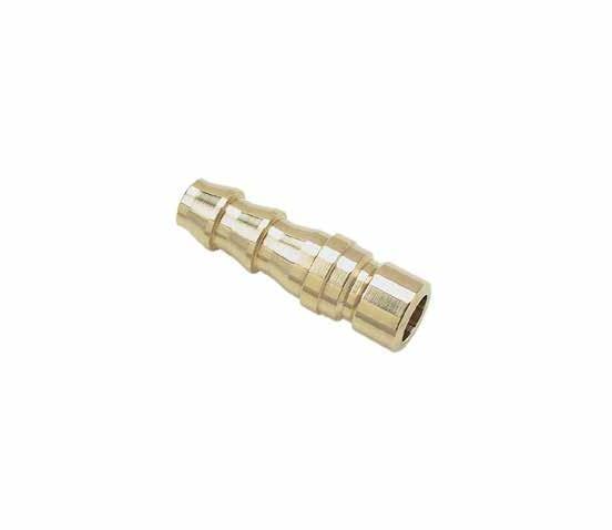
COOLING PRODUCTS E-38
D L M 200 SERIES (1/4” HOLE) 300 SERIES (3/8” HOLE) 500 SERIES (1/2” HOLE) CATALOG NUMBER HOSE I.D. D M L CATALOG NUMBER HOSE I.D. D M L CATALOG NUMBER HOSE I.D. D M L 200-4 1/4 3/16 .875 1.37 300-4 1/4 3/16 .875 1.81 500-8 1/2 13/32 1.062 2.00 200-5 5/16 1/4 .875 1.37 300-5 5/16 1/4 .875 1.81 500-12 3/4 9/16 1.500 2.50 200-6 3/8 1/4 1.062 1.56 300-6 3/8 9/32 1.062 1.81 200-8 1/2 1/4 1.062 1.56 300-8 1/2 11/32 1.062 1.81 D L M Keyed for identification 200 SERIES (1/4” HOLE) 300 SERIES (3/8” HOLE) 500 SERIES (1/2” HOLE) CATALOG NUMBER HOSE I.D. D M L CATALOG NUMBER HOSE I.D. D M L CATALOG NUMBER HOSE I.D. D M L 200-4-K 1/4 3/16 .875 1.37 300-6-K 3/8 9/32 1.062 1.81 500-8-K 1/2 13/32 1.062 2.00 200-6-K 3/8 1/4 1.062 1.56 300-8-K 1/2 11/32 1.062 1.81 500-12-K 3/4 9/16 1.500 2.50
M Brass M Brass
SEALANT TAPE
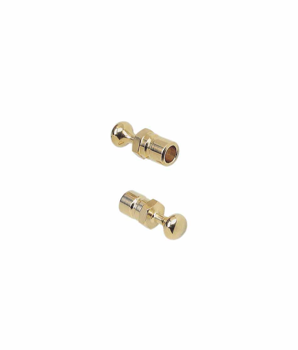
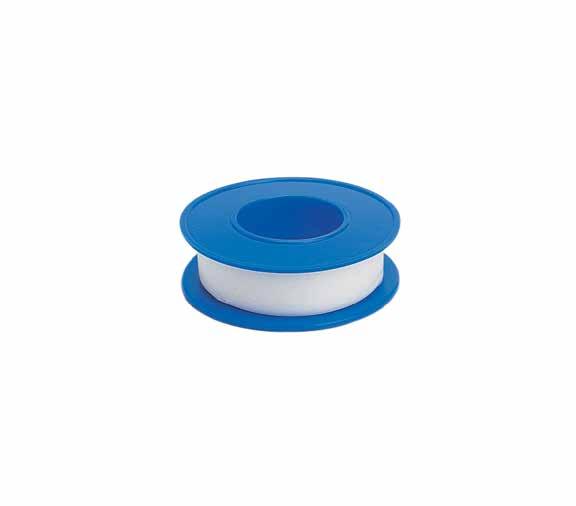
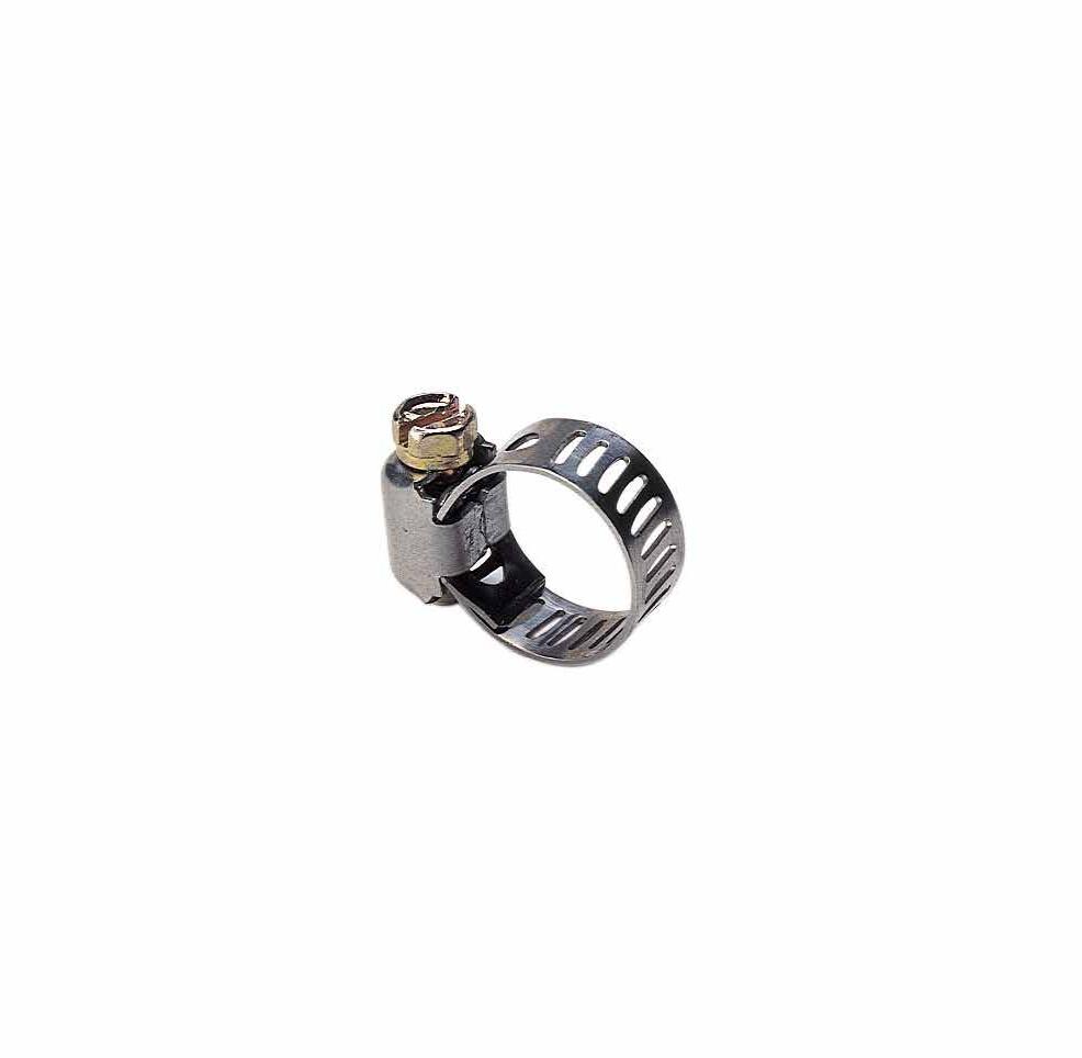
E-39 CATALOG NUMBER DESCRIPTION TT250 1/4” x 520” TT500 1/2” x 520” CATALOG NUMBER HOSE O.D. HC58 5/8 HC78 7/8 HC118 1-1/8 CATALOG NUMBER FITS SOCKET SERIES CP200 200 (1/4”) CP300 300 (3/8”) CP500 500 (1/2”)
CLAMPS
M Brass
Note: M10 includes O-ring.

Note: ELS10 includes O-ring.
COOLING PRODUCTS B A A D M L B A C M B A D M B D A M L L M
CATALOG NUMBER M NPT A B C L MT10 #10-32 UNF .500 .18 .38 .38 MT18 1/8 .66 .53 .56 1.06 MT14 1/4 .91 .76 .71 1.52 MT38 3/8 .97 .84 .81 1.68 MT50 1/2 1.26 1.09 1.00 2.18 CATALOG NUMBER M NPT A B D ELS10 #10-32 UNF .50 .18 .090 ELS18 1/8 .81 .56 .220 ELS14 1/4 .91 .45 .312 ELS38 3/8 .98 .54 .428 ELS50 1/2 1.25 1.03 .522 CATALOG NUMBER M NPT A B D T18 1/8 .55 1.10 .328 T14 1/4 .78 1.56 .422 T38 3/8 .87 1.68 .562 T50 1/2 1.07 2.14 .687 CATALOG NUMBER M NPT A B D ELA18 1/8 .50 .38 .220 ELA14 1/4 .70 .54 .314 ELA38 3/8 .78 .54 .440 ELA50 1/2 1.00 .73 .562 CATALOG NUMBER M NPT L EL18 1/8 .55 EL14 1/4 .78 EL38 3/8 .84 EL50 1/2 1.09 M Brass M Brass M Brass M Brass M Brass MALE
STREET ELBOWS 90˚
STREET ELBOWS
TEES 90˚
ELBOWS 45˚

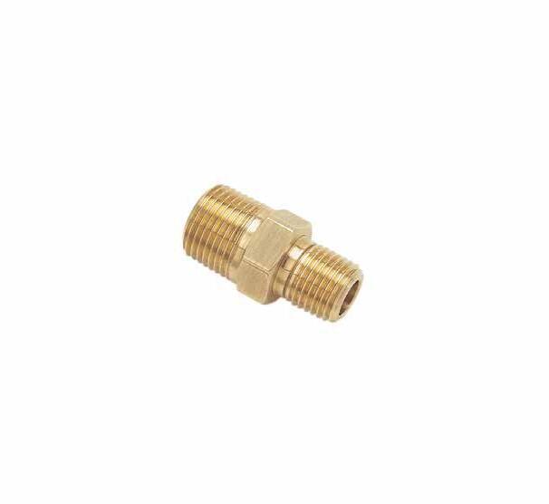
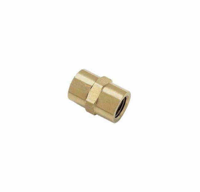
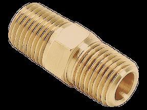
COOLING PRODUCTS E-41 D L M D L P L M CATALOG NUMBER M NPT L D C18 1/8 .75 .328 C14 1/4 1.12 .422 C38 3/8 1.12 .562 C50 1/2 1.50 .688 CATALOG NUMBER M NPT P NPT L D MR18-1 1/8 1/16 1.19 .187 MR14-2 1/4 1/8 1.22 .220 MR38-4 3/8 1/4 1.41 .314 MR50-6 1/2 3/8 1.62 .440 CATALOG NUMBER M NPT HEX SIZE L HN18 1/8 7/16 .969 HN14 1/4 9/16 1.375 HN38 3/8 11/16 1.437 HN50 1/2 7/8 1.813 CATALOG NUMBER M NPT P NPT L D RB18-0 1/8 #10-32 UNF .56 .156 RB18-1 1/8 1/16 .56 .250 RB14-0 1/4 #10-32 UNF .75 .156 RB14-2 1/4 1/8 .75 .328 RB38-4 3/8 1/4 .75 .422 RB50-6 1/2 3/8 1.00 .562 L M M Brass M Brass M Brass M Brass
MALE REDUCERS COUPLINGS HEX NIPPLES
ONLINE RESOURCES
When considering design options, numerous animations can be viewed at procomps.com/animations.
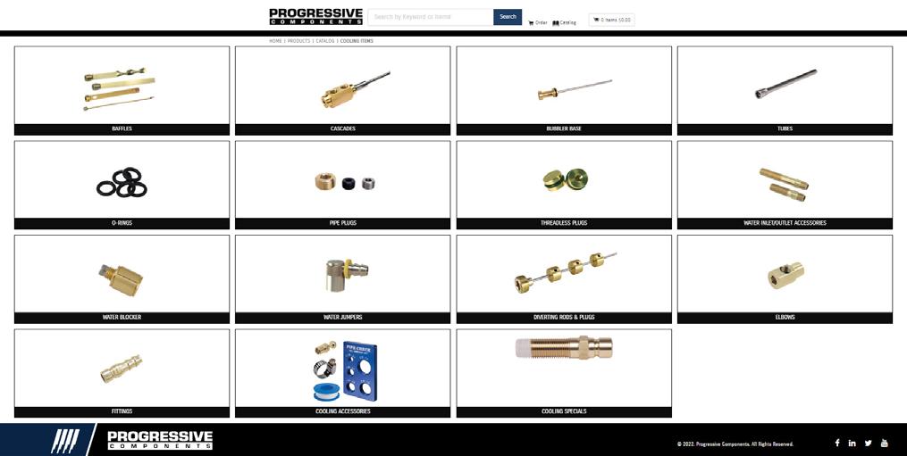
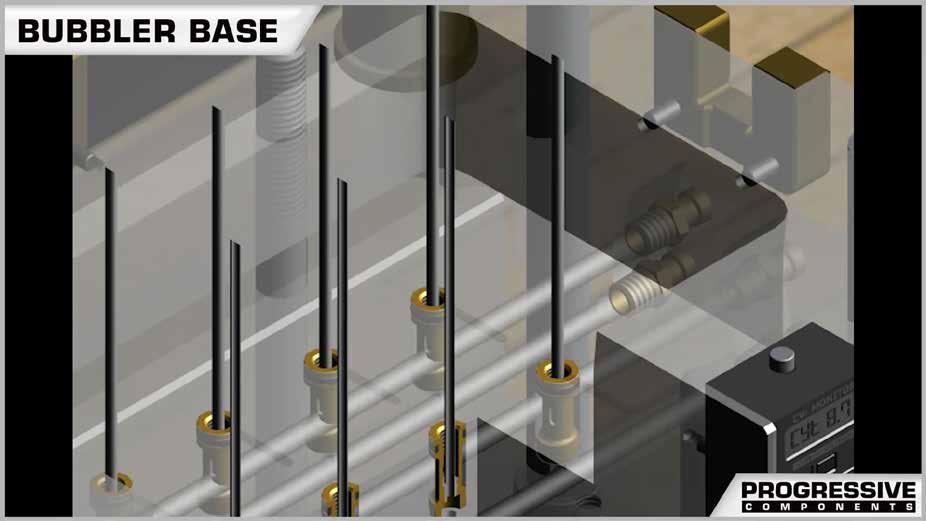
CAD geometry is available online as individual downloads or as part of the CADalog system. The seven formats include: IGES (.igs), ACIS (.sat), STEP (.step), Parasolid (.x_t), SolidWorks (.sldasm), NX (.prt) (Re-Use and MoldWizard) and Visi (.wkf).
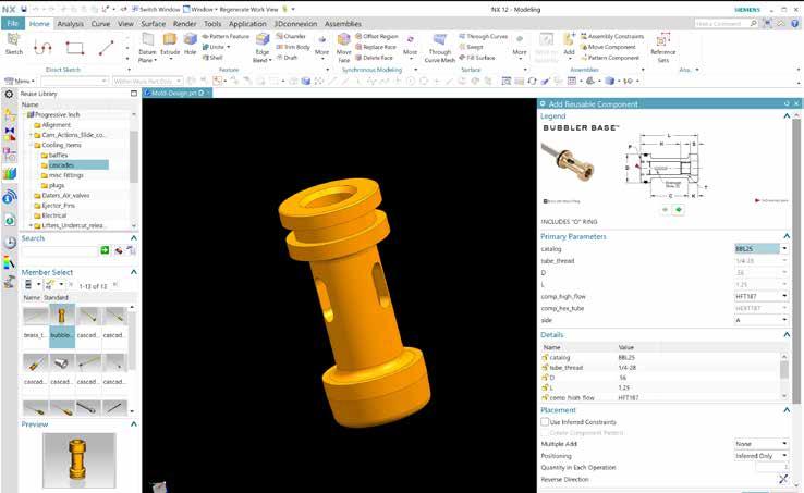
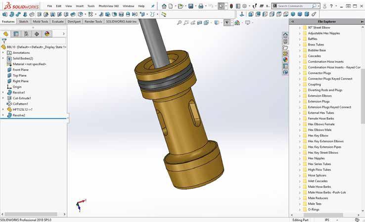
COOLING PRODUCTS E-42
Industry-leading web store expedites the purchasing process. Go to shop.procomps.com for information and additional resources.


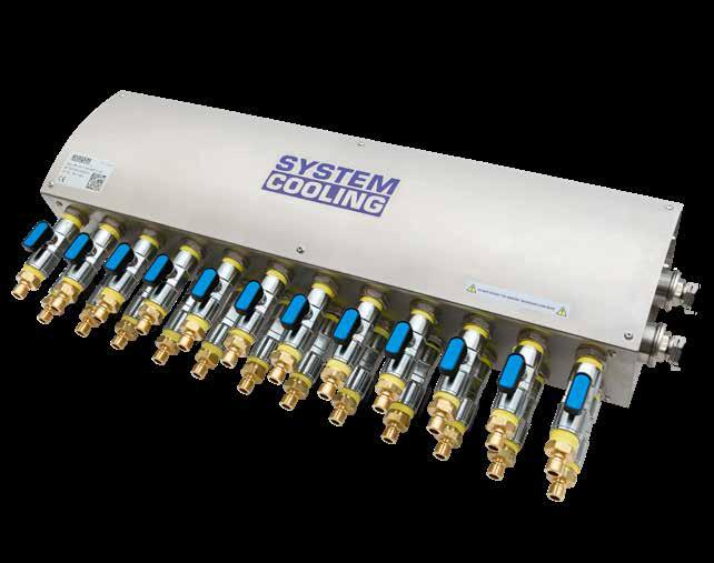

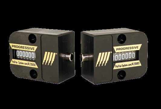
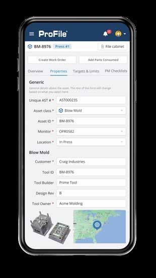


CVe Monitor CVe OnDemand ProFile: Real-Time Monitoring Remote Validation Kit Prefix: CVE Page: F-1 Page: F-3 Page: F-4 Page: F-4 AST000000456 CVeMonitor.com TM Custom Text 1 AST000001234 ProFile-System.com AST00006789 CVeMonitor.com TM AST123456789 Custom Text 2 Custom Text 3 Custom Text 4 ProFile-System.com 000001 AST000000123 ProFile-System.com Custom Text 1 Clearance for #10-32 M4 Button Head Cap Screws ProFile: Asset Management Asset Tags & Plates CounterView: S-Series CounterView: R-Series Prefix: AMTG, CVTG Prefix: CVPL, CVIN, CVPLHT Prefix: CVR-A, CVR-B Page: F-6 Page: F-7 Page: F-8 Page: F-9 Insulator Blocks CV/CVe Cover Plates Mold Trax System Cooling Prefix: CV, CVMM, CVRA Prefix: CV Prefix: SCM Page: F-10 Page: F-12 Page: F-13 Page: F-14
MOLD MONITORING SECTION F
APPLICATION GUIDELINES
• Progressive’s CVe Monitor tracks tool activity, allowing users to view data on the display or from comprehensive reports using OnDemand or the online ProFile system.
• 7-digit LCD display with a push button to move through the display modes.

• 16GB flash drive for file storage.
• Replaceable battery.
• Water resistant with an ingress protection rating of IP58.
• Maximum temperature: 190°F (90°C). For protection against higher temperatures, refer to the Insulators available on pages F-10 and F-11.
• Dimensional compatibility with Progressive’s mechanical CounterViews.
• Mini USB connectivity for data retrieval with cables sold separately on page F-2.
• Cover Plates for protection are sold separately on page F-12.
MOUNTING OPTIONS
and M4 x 25mm SHCS (2)
Block including #8-32 x 1” SHCS (2) and M4 x 25mm SHCS (2)
To Order:
• For installation below parting line (ie. rails as shown in the center graphic above), order (1) CVE and (1) CVE-INT.
• For installation outside of the mold (right graphic), order (1) CVE and (1) CVE-EXT.
ON-MOLD DISPLAY MODES
Each device is provided at -25 cycles to allow for mold set up and initialization of the CVe Monitor. Once it reaches zero (0), all timers and data will reset on the monitor. During production, users can press the button on the front of the monitor and review the following information on the display:
Cycle Count
Total cycles for the life of the mold is presented on the main screen.
Cycle Time
Since the first production cycle, cycle time for the life of the mold.
Cycle Time-Recent
Cycle time for the past 500 cycles is shown in seconds.
Mold Temperature
View current temperature experienced by the monitor (°C) by pressing button twice.


US Patents: 8,899,955, 8,883,054, & 10,715,464. European and Chinese patents applied for and issued.
Efficiency Percentage
The percentage of time that the mold has been actively cycling vs being idle.
Efficiency Percentage-Recent
The percentage of time the mold has been active in the past 500 cycles.
Cycle Count Reset
Press and hold button to reset separate counter to 0 for interim monitoring of cycles.

Flash Drive
Utilize the 16GB flash drive by connecting the CVe to a PC/Tablet with an industry-standard mini USB cable, sold on page F-2.
MOLD MONITORING F-1 CV e MONITOR ®
1.875 (48mm) .938 (24mm) R 5/16 (R 8mm) 1.000 (26mm) 1.125 (28mm) Screws (2) PL 1.500 (38mm) Modify actuator to extend above parting line .170 (4mm) Extension Rod .141ø (3.6mm ) +.015 - .000 +.3 - .0 .394 Actuator Center (10mm) PL 1.125 (28mm) Screws (2) Mounting Block .50 (12.7mm) .25 (6.35mm)
CATALOG NUMBER DESCRIPTION CVE CVe Monitor including #8-32 x 1” SHCS
CATALOG NUMBER DESCRIPTION
Internal Extension
External
(2)
CVE-INT
Rod (8”/200mm) CVE-EXT
Mounting
CV e MONITOR ®
ON DEMAND ALERT MODES
Once data is initialized using the complimentary OnDemand software (from procomps.com/cve-ondemand), users can choose to be alerted to the following sets of conditions for the CVe Monitor.
Preventive Maintenance
During initialization, Preventive Maintenance (PM) checkpoints are entered and saved onto the CVe Monitor. If a PM checkpoint is exceeded, the CVe Monitor enters the PM alert mode and displays both a wrench icon and PM Due as shown at right.
When PM is performed and entered via OnDemand or by the in-mold actuation/button push combination, the next checkpoint.for the PM will be written. If no PM is performed, the CVe Monitor will remain in PM alert mode until the user performs all PMs whose thresholds have been exceeded.
Cycle Time
During initialization, the target cycle time can be written to the monitor using OnDemand. Any variation greater than 2% from the target will enter the alert mode and display the clock icon as shown at right. When the cycle time returns to within 2% of the target, the alert is removed.


Efficiency
During initialization, the target efficiency can be written to the monitor using OnDemand. Any variation greater than 2% from the target will enter the alert mode and display the percentage (%) icon as shown at right. When the efficiency returns to within 2% of the target, the alert is removed.
Low Battery
The CVe Monitor has a battery life of approximately 4 years in typical molding environments where temperatures are controlled. (The battery is 1/2AA lithium non-rechargeable with 3.6V.) When the battery reaches a specified level, the display will show a battery icon as shown at right, and the replacement kit can be ordered separately below.

RETROFITTING
Users can view additional data by double-clicking the button on the monitor.
Retrofit CVe for CounterView Tools
During initialization, molders can start the cycle count with the tool’s actual cycle count from an existing CounterView or known cycles from maintenance records. Once entered, the user can see the total cycles for the tool, which includes the count of the cycles from the counter and those run with the CVe Monitor.
In the graphic at right, the tool had 1,000,000 cycles on it originally, but ran 507,288 after the CVe Monitor was installed.
CABLES AND CONNECTIVITY
Using a USB cable, users can connect the CVe Monitor to their computer or tablet and view data in OnDemand, outlining the reason for the report generation. Notes can be included and user information is recorded for historical reference. More details about OnDemand are on the following pages.
CVEL-DATA9 USB 2.0 to Type B Mini 9 Foot Long, Right-Angle Cable
CVEL-DATA9S USB A to Type B Mini 9 Foot Long, Straight Cable CVE-USB-15
2.0 to Type B Mini, 15 Foot, Common Straight Cable
MOLD MONITORING F-2
CATALOG NUMBER DESCRIPTION
CVE-REPLKIT
v3
Monitor. CVe Ini alize Date November 23, 2017December 17, 2017 Device IDOKX1234 OKX1234 Tool ID8565B 8565B Part ID Blower Housing ABT57 Blower Housing ABT57 Program Name MochaMocha Customer Crimson FanCrimson Fan Target Efficiency %N/A 94% Target Cycle TimeN/A 7.5 Ini al PM Point50000 50000 Target PM Interval 100000 100000 Cycles Prior to CVe Installa on* 10000001000000 OEM ID N/AABT1 ASSET ID N/A0356-5686 Date/TimeBa eryCycles OD UserConn. ByCompany Des na on RE V PM RE P GEN REV# Notes October 4, 2018 OK 507,288 INJECTI1 Blake Fitz Injec on Tech CrimsonQ@crmn.com NN YN N/AReplaced damaged core pin in cavity 4 October 4, 2018 OK 506,524 INJECTI1 Blake Fitz Injec on Tech CrimsonQ@crmn.com NNN YN/A Data Pul September 19, 2018 OK 491,274 INJECTI1 Blake Fitz Injec on Tech CrimsonQ@crmn.com NN YN N/A Pulled from produc on for mold opera onal issues. It is being sent for eval on and rework September 15, 2018 OK 482,567 MOLDHOU1 Chuck LouseMold House CrimsonQ@crmn.com NY NN N/AFull PM: Cavity #2 was shutoff June 28, 2018 OK 364,001 MOLDHOU1 Chuck LouseMold Hous CrimsonQ@crmn.co NY NN N/AFull PM May 31, 2018 OK 314,856 MOLDHOU1 Chuck LouseMold House CrimsonQ@crmn.co NY NN N/AFull PM April 28, 2018 OK 260,002 MOLDHOU1 Chuck LouseMold House CrimsonQ@crmn.com NY NN N/AFull PM: Cavity #2 was shutoff April 4, 2018 OK 211,563 MOLDHOU1 Chuck LouseMold House CrimsonQ@crmn.com NY NN N/AFull PM March 22, 2018 OK 193,268 INJECTI1 Blake Fitz Injec on Tech CrimsonQ@crmn.com NN YN N/A3 cavi es are shutdown. Pulled for evalua on and repair February 7, 2018 OK 106,235 MOLDHOU1 Chuck LouseMold House CrimsonQ@crmn.com NY NN N/AFull PM January 10, 2018 OK 58,725 MOLDHOU1 Chuck LouseMold House CrimsonQ@crmn.com NY NN N/AFull PM December 17, 2017 OK 9,265 MOLDHOU1 Chuck LouseMold House CrimsonQ@crmn.com NY NN N/A Ini al mold inspec on. There is no wear or damage to mold following ini al run. Targets are set. Mold is released for produc on November 23, 2017 OK 0 MOLDHOU1 Chuck LouseMold House CrimsonQ@crmn.com NNN YN/A Mold is completed and released for sampling OnDemand Ac vity Log [So ware Version 3.1.0/2.6.1/3.1.9] Reason for connec ng CVe Monitor US Patents: 8,899,955, 8,883,054, & 10,715,464. European and Chinese patents applied for and issued.
USB
Battery Replacement Kit for the
CVe
Drive comprehensive reporting using data from the CVe Monitor when running OnDemand software, available at no charge from procomps.com/cve-ondemand. OnDemand software enables the user to generate Adobe Acrobat (.pdf), Excel (.xls), and encrypted (.enc) reports to share with customers and other colleagues with these metrics:
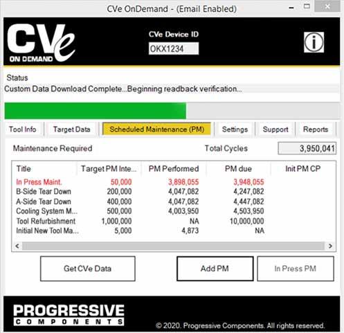
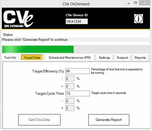
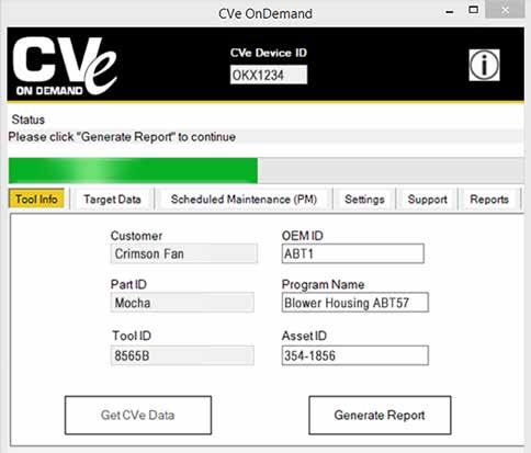
A: When the CVe is initialized, users can identify their tool and align with the device serial number which is tracked on reports utilizing different field options.
B: The target cycle times and efficiency percentages can be entered. OnDemand also supports ten languages: English, German, Mandarin, Spanish, French, Italian, Japanese, Korean, Portuguese and Thai. Reports, generated in the chosen language, compare actual values to targets, providing a quick view of any variances.
C: Statistics are provided to show quantity of total cycles and inactivity for the life of the tool.
D: Weekly sessions are presented graphically to show production efficiency levels.
E: Weekly cycle time and maximum mold temperature tracking identifies tools with variances over the past year.
F: The productivity portion of the report takes the target preventive maintenance (PM) points set by the molder and compares them to actual maintenance pulls.
G: The Maintenance Tab has nine user-definable PM points. In addition, customers can perform maintenance without having their laptop or computer near the CVe Monitor. By holding down the button, cycling the monitor once, and releasing the button, an event will be recorded. This is then added to the OnDemand reports when run.
MOLD MONITORING F-3 CV e ONDEMAND ®
1 000 000 50000 10,000Cycles-Target Ta get PM Interval 50,000 9,265 Cycles-Actua Cycles until PM 25 279 Initial PM Point: Next PM Due: Intermediate Preventive Maintenance 92% 8.5 Life-To-Date Cycle Time Life-To-Date Efficiency % Report 764 Part ID: Blower Housing ABT57 Tool ID: 8565B Hours in Sleep Mode Hours in Ac ve Mode PM 24,721 0 Produc vity Efficiency Cycles since last Target Efficiency (% 5% Legend 2% Target Cycle Time 111 Repair Part Revision General Query 2%-5% 6,287 7.2 100% 94% Since Last Report Cycle Time Crimson Fan Performance Summary Since Last Report Efficiency % Last Full Week Cycle Time Hours Idle Device ID: OKX1234 Program: Green OEM ID: ABT1 Asset ID: 354-1856 04 Oct 2018 507,288 94% 1,197 Outside Target Last Full Week Efficiency % 7.4 Between Life-To-Date Cycles Cycles Prior to CVe Installation* Cycle Time Never 764 Within Target 7.5 0 50 100 150 200 4 days 30 -Sep-1 8 23 -Sep-1 8 16 -Sep-1 8 9Se p18 2Se p18 26 -Aug -1 8 19 -Aug -1 8 19 -Aug -1 8 19 -Aug -1 8 19 -Aug -1 8 12 -Aug -1 8 5Au g18 29 -Jul -1 8 22 -Jul -1 8 15 -Jul -1 8 8Jul-18 1Jul-18 24 -Jun -1 8 17 -Jun -1 8 10 -Jun -1 8 3Jun18 27 -M ay -1 8 20 -M ay -1 8 13 -M ay -1 8 6Ma y-18 29 -Apr -1 8 22 -Apr -1 8 15 -Apr -1 8 8Apr-18 1Ap r18 25 -Mar -1 8 18 -Mar-1 8 11 -Mar -1 8 4Ma r18 25 -Feb-1 8 18 -Feb-1 8 11 -Feb-1 8 4Fe b18 28 -Jan-1 8 21 -Jan-1 8 14 -Jan-1 8 7Jan-18 31 -Dec-1 7 24 -Dec-1 7 17 -Dec-1 7 10 -Dec-1 7 Ac ve Time Idle Time Sleep Time 30 40 50 60 70 5 6 7 8 9 10 11 12 13 da ys 30 -S ep-1 23 -S ep-1 16 -S ep-1 9Se p-18 2Se p-18 26 -Aug-1 19 -Aug -1 19 -Aug-1 19 -Aug-1 19 -Aug -1 12 -Aug-1 5Aug18 29 -J ul -1 22 -J ul -1 15 -J ul -1 8Ju 18 1Ju 18 24 -J un -1 17 -J un -1 10 -J un -1 3Ju n18 27 -M ay -1 20 -May -1 13 -May -1 6Ma y18 29 -Apr-1 22 -Apr-1 15 -Apr-1 8Ap r18 1Ap r18 25 -Mar-1 18 -Mar-1 11 -Mar-1 4Ma r-18 25 -Feb-1 18 -Feb-1 11 -Feb-1 4Feb-18 28 an -1 21 an -1 14 an -1 7Ja n-18 31 -D ec -1 24 -D ec -1 17 -D ec -1 10 -D ec -1 Life-To-Date Weekly Out of Range > 25% Temperature Deg C 0 2,000 4,000 6,000 8,000 10,000 12,000 14,000 16,000 18,000 da ys 30 -S ep -1 8 23 -S ep -1 8 16 -S ep -1 8 9Se p18 2Se p18 26Au g18 19Au g18 19 -A ug -1 8 19 -A ug -1 8 19Au g18 12Au g18 5Au g18 29 -J ul -1 8 22Ju l18 15Ju l18 8Jul18 1Jul18 24Ju n18 17Ju n18 10 -J un -1 8 3Ju n18 27May18 20May18 13 -M ay -1 8 6May18 29Apr-18 22Apr-18 15Apr-18 8Ap r18 1Ap r18 25 -M ar -1 8 18 -M ar -1 8 11Ma r18 4Mar-18 25 -F eb -1 8 18 -F eb -1 8 11Fe b18 4Fe b18 28Jan -1 8 21Jan -1 8 14Ja n18 7Jan -1 8 31 -D ec-1 7 24 -D ec-1 7 17Dec-1 7 10Dec-1 7 Hours Total Cycles pe Week Cycle Time= Active Ti Tota Cycl Active Time is the accumulation of all time the monitor is cycling. Idle Time begins after 200 seconds of inactivity Once Idle Time counts to 6 hours the time is transferred to Sleep Time and continues to accumulate until monitor is cycled Seconds Cycles PM Target Exceeded Maintenance Required PM PerformedRepairRevisionGeneral Query 354-1856 ID Asse D OEM Name: Program D Tool 487 63 000 1 487 63 Date Due PerformedOverdue Date Due PerformedOverdue 1028 47015 45987 19 10 2019 18 6 194 51416 51222 36 3 2019 22 8 522 32950 32428 07 15 2019 15 4 178 44867 44689 57 0 2019 12 8 458 34095 33637 43 12 2019 22 5 177 61534 61357 00 0 2019 11 9 413 20748 20335 57 12 2018 9 5 168 41401 41233 04 16 2019 8 8 327 27831 27504 07 15 2019 27 2 140 58297 58157 00 0 2019 9/8 256 48052 47796 02 5 17/2019 7 139 57156 57017 07 15 2019 4 9 238 25188 24950 26 1 26/2018 9 110 54844 54734 21 21 2019 28 8 219 22813 22594 43 6 11/2018 8 100 29052 28952 33 4 2019 26 7 194 51416 51222 36 3 22/2019 8 100 27596 27496 40 19 2019 22 7 189 26310 26121 31 17 2019 31 1 99 33736 33637 19 22 2019 1 8 178 44867 44689 57 0 12/2019 8 97 46084 45987 50 9 2019 15 8 177 61534 61357 00 0 11/2019 9 97 25047 24950 48 10 2019 19 7 168 41401 41233 04 16 2019 8 8 95 47891 47796 43 18 2019 18 8 157 21295 21138 28 12 2018 3 7 95 32523 32428 26 13 2019 29 7 140 58297 58157 00 0 8/2019 9 88 56917 56829 14 6 2019 9/1 139 57156 57017 07 15 2019 4 9 87 37222 37135 12 7 2019 8/5 110 54844 54734 21 21 2019 28 8 80 63487 63407 00 0 2019 13 9 100 47997 47897 33 4 26/2019 7 78 53678 53600 28 12 2019 25 8 Tota Percentage Tota Percentage 1% 96 1420 7% 90 68 7% 2 40 7% 2 2 2% 1 18 7% 6 5 0% 100 1478 0% 100 75 Tota Mainte On Time Maintenance Overdue Main enance (<10%) Overdue Main enance (>10%) On Time Maintenance Overdue Maintenance (<10%) Overdue Maintenance (>10%) Tota Main Crimson Fan In-Press Tool Maintenance Report Device ID: OKX1234 13-Sep-19 Bl Ho ing ABT50 D t P ABT1 h M 8565B Date of last In-Press Maintenance Last In-Press Maintenance Current Cycle CountCycles unti In-Press Maintenance Trailing 5 weeks Overdue Maintenan Life to Date Overdue Maintenance Previous 100 In-Press Maintenance Events Historical In-Press Maintenance Summary 9/13/1019 9:44 Life To Date On-Time PM Ov du PM (<10%) Overdue PM (>10%) Trailing 5 Weeks On-Time PM Overdue PM (<10%) Overdue PM (>10%) -150 -100 -50 0 50 100 150 200 250 9/13/ 20 19 9: 44 9/ 12 /2 01 12: 08 9/ 11 /2 01 14: 32 9/ 10 /2 01 16: 56 9/9/20 19 19:2 9/8/20 19 21:4 9/8/20 19 0:08 9/7/20 19 2:32 9/6/20 19 4:56 9/5/20 19 7:20 9/4/20 19 9:44 9/3/20 19 12:0 9/2/20 19 14:3 9/1/20 19 16:5 8/ 31 /2 01 19: 20 8/ 30 /2 01 21: 44 8/30/ 20 19 0: 08 8/29/ 20 19 2: 32 8/28/ 20 19 4: 56 8/27/ 20 19 7: 20 8/26/ 20 19 9: 44 8/ 25 /2 01 12: 08 8/ 24 /2 01 14: 32 8/ 23 /2 01 16: 56 8/ 22 /2 01 19: 20 8/ 21 /2 01 21: 44 8/21/ 20 19 0: 08 8/20/ 20 19 2: 32 8/19/ 20 19 4: 56 8/18/ 20 19 7: 20 8/17/ 20 19 9: 44 8/ 16 /2 01 12: 08 8/ 15 /2 01 14: 32 8/ 14 /2 01 16: 56 8/ 13 /2 01 19: 20 8/ 12 /2 01 21: 44 8/12/ 20 19 0: 08 8/11/ 20 19 2: 32 8/10/ 20 19 4: 56 8/9/20 19 7:20 8/8/20 19 9:44 8/7/20 19 12:0 8/6/20 19 14:3 2 8/5/20 19 16:5 6 8/4/20 19 19:2 0 8/3/20 19 21:4 4 8/3/20 19 0:08 8/2/20 19 2:32 8/1/20 19 4:56 7/31/ 20 19 7: 20 7/30/ 20 19 9: 44 7/ 29 /2 01 12: 08 7/ 28 /2 01 14: 32 7/ 27 /2 01 16: 56 7/ 26 /2 01 19: 20 7/ 25 /2 01 21: 44 7/25/ 20 19 0: 08 7/24/ 20 19 2: 32 7/23/ 20 19 4: 56 7/22/ 20 19 7: 20 7/21/ 20 19 9: 44 7/ 20 /2 01 12: 08 7/ 19 /2 01 14: 32 7/ 18 /2 01 16: 56 7/ 17 /2 01 19: 20 7/ 16 /2 01 21: 44 7/16/ 20 19 0: 08 7/15/ 20 19 2: 32 7/14/ 20 19 4: 56 7/13/ 20 19 7: 20 7/12/ 20 19 9: 44 7/ 11 /2 01 12: 08 7/ 10 /2 01 14: 32 7/9/20 19 16:5 7/8/20 19 19:2 7/7/20 19 21:4 7/7/20 19 0:08 7/6/20 19 2:32 7/5/20 19 4:56 7/4/20 19 7:20 7/3/20 19 9:44 7/2/20 19 12:0 7/1/20 19 14:3 6/ 30 /2 01 16: 56 6/ 29 /2 01 19: 20 6/ 28 /2 01 21: 44 6/28/ 20 19 0: 08 6/27/ 20 19 2: 32 6/26/ 20 19 4: 56 6/25/ 20 19 7: 20 6/24/ 20 19 9: 44 6/ 23 /2 01 12: 08 6/ 22 /2 01 14: 32 6/ 21 /2 01 16: 56 6/ 20 /2 01 19: 20 6/ 19 /2 01 21: 44 6/19/ 20 19 0: 08 6/18/ 20 19 2: 32 6/17/ 20 19 4: 56 6/16/ 20 19 7: 20 6/15/ 20 19 9: 44 Main te na nc e On-T im e Date d Ti Of Maintena US Patents: 8,899,955, 8,883,054, & 10,715,464. European and Chinese patents applied for and issued.
REAL-TIME MONITORING
For real-time monitoring of tools, Progressive provides hardware and website access for OEMs and molders utilizing the CVe Monitors.
Features:
• Utilizes FCC and CE certified internal components.
• Press Modules act as a node on a network, reducing the distance required in the plant for data submission to the Gateway.
• Radio Frequency (RF) antennas are interference-free in typical molding environments.


• Designated website for data collection, reporting, and file storage.
HARDWARE
Press Module
• 1 per press connects to the CVe Monitor via cables
• Power supply (US/International) included
• Sends data to the Gateway continuously
• Serves as a node on the network for tools running with a CVe Monitor
• Includes (1) CVEL-DATA9 Cable
PROFILE ® REMOTE VALIDATION KIT
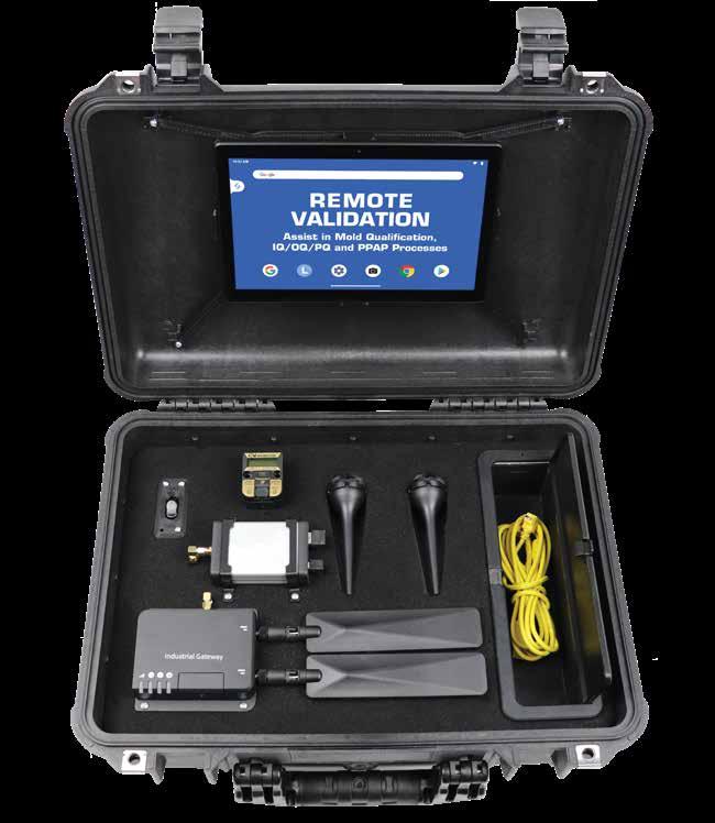
Gateway
• 1 per facility collects data from all press modules installed via RF transmissions
• Accesses the internet via cellular technology
• Sends data to the customer’s web portal every 15 minutes
Using the ProFile website interface, the Remote Validation Kit eliminates the need to travel to mold trials and qualifications to gather information. Real-time data is available by connecting the portable system to the CVe Monitor on the mold.
• Can be easily moved between sites as qualifications dictate.
• Reduces or eliminates travel to mold qualifications.
• Users can upload and share files or documents including mold validation data, part drawings, process sheets, and quality inspection reports with global access.
• Monitor critical KPIs without being onsite.

• Generate real-time graphs and reports.
• Includes all hardware, antennas, and cables in a sturdy case. CVe Monitors and tablets are sold separately.
Contact Customer Service for a ProFile or Remote Validation Kit quotation.
MOLD MONITORING F-4
PROFILE ®
US Patents: 8,899,955, 8,883,054, & 10,715,464. European and Chinese patents applied for and issued.
REAL-TIME MONITORING
ProFile Website Features:
• Secure access for OEMs and molders via the website or mobile app.
• Customizable dashboards allow role-based views of all assets. Users can easily see asset location and key metrics around performance and maintenance.


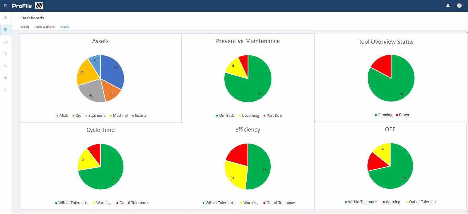
• Users can easily create custom searches and views based on their needs.
• Graphs include cycle times, efficiencies, cavitation, production loss, and preventive maintenance.
• Preventive Maintenance (PM) function allows for user-defined PM intervals.
• Users can create or customize PM forms and checklists for a specific maintenance program.
• The Work Order function allows users to create work orders for molds, machines, or other assets.
• GPS tracking allows for users to view the location of all tools by scanning a QR code using a GPS-enabled device. This feature is ideal for managers that are tracking multiple facilities or global operations. (Asset Tags sold separately on page F-7.)
• The file cabinet system is designed to store reports, tool and part drawings, and set-up sheets and can be utilized by customers with ProFile access.
• OEE is calculated for molds and equipment to identify for the both the press and the tool, which allows tooling and manufacturing operations to have separate OEE calculations to distinguish between equipment and tooling issues.
• User-defined fields make customizing data simple for tools, presses, and assets.
• APIs can be written to allow data sharing between existing ERP/MES systems.
MOLD MONITORING F-5 PROFILE ®
Global view of all assets by location, quantity, and class.
US Patents: 8,899,955, 8,883,054, & 10,715,464. European and Chinese patents applied for and issued.
Customizable Performance Dashboard showing status and KPIs.
ASSET MANAGEMENT SYSTEM
The ProFile tracking system is a comprehensive solution for managing assets. The cloud-based system organizes assets and stores related documents and photos, while also logging GPS locations.

Several options of Asset Tags and Plates are offered on the following page.
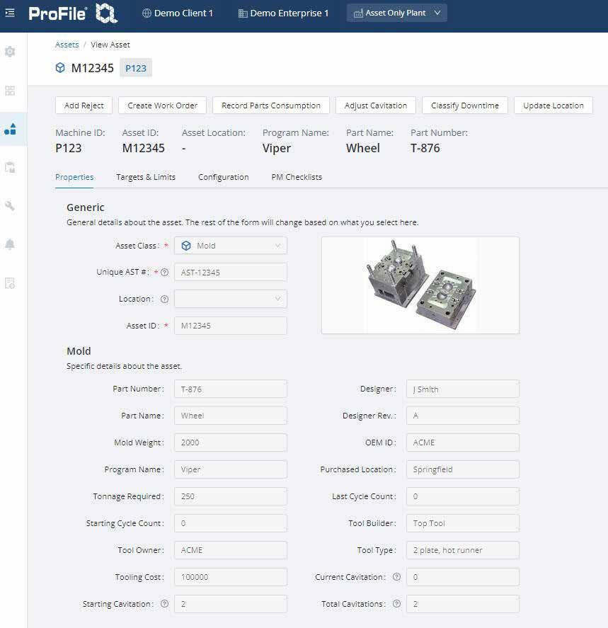
• Different asset types require different types of data. ProFile offers five asset classes (molds, dies, machines, equipment, and inserts) with customizable asset types under each class. There are also several user defined fields to give users increased flexibility.
• Each asset page includes a filing cabinet to store critical documents associated with that asset. These documents can be easily accessed and shared by users with permissions. Users have 10GB of storage associated with their asset database.
• When logging in to ProFile via ProFile-System.com, the dashboard shows a breakdown of assets in the system by asset class. Clicking on any of the asset classes on the chart will drill down to the detailed listing. Also, the dashboard shows Preventive Maintenance status of assets for easy access to overdue PMs.
• See a complete list of all assets in one place or choose the tab for the asset class filter. All fields on the tool listing are sortable using the header fields.
Mobile Functionality and GPS
• Scan the QR code on the Asset Tags or Plates on your mobile device to see a summary view of the assets. To see additional data, press the details button. Every time a QR code is scanned, the GPS location is pushed to the cloud and recorded on the asset page.
• Preventive Maintenance and Work Orders can be scheduled.
• Users can create checklists and assign them to assets to view how many cycles or date assets require maintenance. To schedule maintenance or other activities, Work Orders can be utilized to track unscheduled maintenance and repairs for assets.
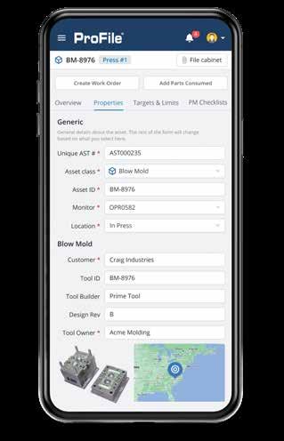
• For a demonstration or to set up an account for ProFile system access, contact Customer Service.

MOLD MONITORING F-6 PROFILE ®
Dashboard Assets Customers Activity Reports Administration Dashboard Welcome to the ProFile Asset Management System Preven�ve Maintenance Assets On Schedu e 7 Past Due 3 Mo d 3 D e 3 Equ pment 2 Press 2 23 4 2 O T k Up g P t D 55 23 40 35 15 Mo d D e Equ ment Mach ne n e ts
US Patents: 8,899,955, 8,883,054, & 10,715,464. European and Chinese patents applied for and issued.
ASSET TAGS AND PLATES
SPECIFICATIONS: STANDARD TAGS
• Two sizes available. Small versions fit on CounterViews. Refer to page F-8.
• 8 mils thick aluminum, brushed finish.
• 3M 467 adhesive can be affixed to standard tool steel. Max temp 300°F (150°C).
• Serial number (AST prefix) is established by Progressive and aligns to customer-specific asset identification within ProFile-System.com.
• Minimum order quantity is 25 tags of any type and must be purchased in increments of 25.
• ProFile account required and established at time of purchase.
SPECIFICATIONS: STANDARD PLATES
• Size: 4” x 2”
• 20 mils thick aluminum.
• Provides heat resistance for assets up to 600°F (315°C).
• Bolts to mold base/asset with included button head cap screws.
• Minimum order quantity is 25 plates and must be purchased in increments of 25.
• ProFile account required and established at time of purchase.
CUSTOM TAG & PLATE ORDERING
• Specifications are same as standard Tags and Plates, shown above.
• Layout is as shown at left below, but the text can vary based on your requirements as shown on the sample at right. Also, the color can be selected to match your company’s logos. All custom Tags/Plates include the QR code and unique serial number. Refer to the template at procomps.com to submit your quote request.
• Minimum order quantity = 50 for 4x2” Plates and Tags; 100 for the 1.25 x .5” tags.
AST123456789
• Delivery for initial order is 3 weeks, including proof time.
1
AST123456789
AST123456789
MOLD MONITORING F-7 PROFILE ®
INFORMATION AST000000456 CVeMonitor.com TM AST123456789 Custom Text 1 Custom Text 2 Custom Text 3 Custom Text 4 AST000001234 ProFile-System.com AST00006789 CVeMonitor.com TM AST123456789 Custom Text 2 Custom Text 3 Custom Text 4 ProFile-System.com 000001 000001 CVeMonitor.com 000001 AST000000123 ProFile-System.com Custom Text 1 Clearance for #10-32 / M4 Button Head Cap Screws 3.6 1.6 Asset # Part #
000001 TOP MOLDING
TOP MOLDING
Custom Text
Custom Text 2 Custom Text 3 Custom Text 4
Custom Text 2 Custom Text 3 Custom Text
ProFile-System.com 000001 000001 TM CVeMonitor.com 000001 Custom Text
CATALOG NUMBER SIZE DESCRIPTION AMTG-S24 4” x 2” ProFile Asset Tag-Large AMTG-S15 1.25” x .5” ProFile Asset Tag-Small CATALOG NUMBER SIZE DESCRIPTION AMTG-P24 4” x 2” ProFile Asset Plate
4
1
AST000000456 CVeMonitor.com TM AST123456789 Custom Text 1 Custom Text 2 Custom Text 3 Custom Text 4 AST000001234 ProFile-System.com AST00006789 CVeMonitor.com TM AST123456789 Custom Text 2 Custom Text 3 Custom Text 4 ProFile-System.com 000001 000001 CVeMonitor.com 000001 AST000000123 ProFile-System.com Custom Text 1 Clearance
3.6 1.6
for #10-32 / M4 Button Head Cap Screws
APPLICATION GUIDELINES
• Maximum operating temperatures:
– 250˚F (120˚C) Standard CounterView
– 375˚F (190˚C) High Temp CounterView
• Counter: Non-resettable mechanical, 7-digit
• Available for installation on the movable or stationary halves and with extensions.
• For heat protection, refer to the Insulators available on pages F-10 and F-11.
• Cover Plates for protection are sold separately on page F-12


• CounterViews can be ordered pre-set to a specific cycle count. Contact Customer Service for more information.
Mounting Options
Parting Line Mount Parting line mount makes unit easily visible to operator.
Extension Mount Machinable 8” (200mm) included extension rod allows installation in support plate or rail. Not available for High Temp Counterviews.
No pocket machining necessary. Designed specifically for retrofit applications. Order the Parting Line Mount and the CVE-EXT Block as shown below.
Operator Side: Movable Half / B Side
Operator Side: Stationary Half / A Side
CVIN-B Standard: Internal Extension CVPLHT-B High Temp: Parting Line
Screws included.
ACCESSORIES
CVPL-A Standard: Parting Line
CVIN-A Standard: Internal Extension
CVPLHT-A High Temp: Parting Line
Screws included.
MOLD MONITORING F-8
NUMBER VERSION
COUNTERVIEW ® CATALOG
& MOUNTING STYLE
CATALOG NUMBER DESCRIPTION CVE-EXT External Mounting Block including #8-32 x 1” (2) and M4
(2) CVID ID Plate for CounterView
x 25mm screws
CATALOG NUMBER VERSION & MOUNTING STYLE CVPL-B Standard: Parting Line
External Mount
Internal
0 0 0 0 0 0 0 .250 (6mm) 1.125 (28mm) PL .500 (12mm) 0 0 0 0 0 0 0 PL .465 (12mm) Modify actuator to extend above parting line .170" (4mm) .375ø (10mm) .750 (19mm) +.005 -.000 0 0 0 0 0 0 0 1.875* (48mm) .938 (24mm) 1.500 (38mm) R 5/16 (R 8mm) #8-32 x 1" and M4-.7 x 25mm SHCS (2) Included 1.000 (26mm) 1.125 (28mm) PL *Pocket Tolerance: 1.875/48mm for .004" (.1mm) PL gap
Nylon
M Glass-filled
housing
A A B B C C
APPLICATION GUIDELINES
• Counter: Non-resettable mechanical, 7-digit


• Available for installation on the movable or stationary halves and with extensions.
• Maximum operating temperature is 250˚F (120˚C). For heat protection, refer to the Insulator available on page F-10.
• CounterViews can be ordered pre-set to a specific cycle count. Contact Customer Service for more information.
Right
Backup Plate or insert
Cavity Plate 1.875" (47mm)
.160 ±.01 (4mm ±.25) Actuation required. (If actuator rod is to be modified, this dimension should be maintained.) .195 Typical (5mm)
The R-Series CounterView can be installed in the A or B plates with a minimum thickness of 1.875” (47mm). Larger plates utilize a threaded rod (included with each) that is pre-machined to the appropriate length for standard plate thicknesses to provide consistent actuation.

Backup Plate or insert
Cavity: Variable Thickness
Operator Side: Movable Half / B Side
Actuator length is provided in nominal increments, but longer lengths can be purchased and modified to suit the plate thickness and back up insert or plate.
Metric Standard
Cavity Plate 1.875" (56mm)
Backup Plate or insert
Left
Cavity: Variable Thickness
Backup Plate or insert
CAD insertion point
Operator Side: Stationary Half / A Side
Inch Standard Metric Standard
Each R-Series CounterView includes the actuator. All except CVR-B-18 and CVR-A-18 require attachment of the actuator rod to the threaded CounterView unit.
MOLD MONITORING F-9 COUNTERVIEW ®
Left hand CounterView mounted in A Plate (CVRL-23 shown)
A Plate B Plate
PL
hand (actuated with parting line on the right) CounterView mounted in B Plate (CVR-B-18 shown)
A Plate B Plate
Plate PL
Left hand CounterView mounted in A Plate (CVRL-23 shown)
PL
Installation
hand (actuated with parting line on the left) CounterView mounted in A Plate (CVR-A-23 shown)
9999950 .750* 1.840 1.625 +.010 -.000 +.000 -.001 ± .005 ± .12 +.005 -.000 Standard Plate Thickness +.005 -.000 +.25 -.00 +.12 -.00 +.12 -.00 .50 .875 .28 [7 mm] THRU TO P/L R .03 [.75mm] max, typical *Light press fit +.00 -.02 *Light press fit 19.05* 46.75mm Standard Plate Thickness 41.25 12.5mm 22.25 mm 7 THRU TO P/L .75 R max. .75 R max. [ [ [ [ [ [ [ [ +.25 -.00 [41.25mm [ Patent No. EP1567924 issued throughout Europe and South Africa. Chinese Patent No. ZL200380109407.8 issued. CATALOG NUMBER NOMINAL PLATE THICKNESS CVR-A-18 1.875 CVR-A-23 2.375 CVR-A-28 2.875 CVR-A-33 3.375 CVR-A-38 3.875 CVR-A-43 4.375 CVR-A-83 8.375 CATALOG NUMBER NOMINAL PLATE THICKNESS CVR-A-56 56 CVR-A-66 66 CVR-A-76 76 CVR-A-96 96 CVR-A-116 116 CVR-A-196 196 CATALOG NUMBER NOMINAL PLATE THICKNESS CVR-B-18 1.875 CVR-B-23 2.375 CVR-B-28 2.875 CVR-B-33 3.375 CVR-B-38 3.875 CVR-B-43 4.375 CVR-B-83 8.375
Standard CATALOG NUMBER NOMINAL PLATE THICKNESS CVR-B-56 56 CVR-B-66 66 CVR-B-76 76 CVR-B-96 96 CVR-B-116 116 CVR-B-196 196
Inch
Nylon
M Glass-filled
housing
INSULATOR BLOCKS EXTERNAL MOUNT
• Maximum temperature: 360°F (180°C).
APPLICATION GUIDELINES
• Installation can be on the cavity or core half of the tool. For use with ProFile, mount to the stationary half for optimum cable routing.
• The Inch or Metric Insulator Block accepts the screws from the S-Series CounterView sold on page F-8 or the CVe Monitor sold on page F-1.
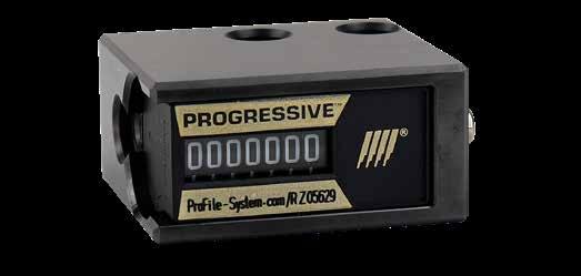
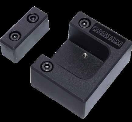
BLOCK
R-Series CounterViews are sold separately on page F-9.
Note: The width of the Actuation Block is smaller by 1/16” to allow for clearance if the CounterView Block is recessed into the mold.
MOLD MONITORING F-10
CATALOG NUMBER DESCRIPTION HI WI TI SI S2 H2 W2 T2 S3 S4 CV-BLK Inch version with screws: (2) 1/4-20 x 1-1/8 (Actuator) (2) 1/4-20 x 1-1/2 (Block) 2.37 3.00 1.37 2.25 .50 .75 2.00 1.00 1.00 .37 CVMM-BLK Metric version with screws: (2) M6-1.0 x 30 (Actuator) (2) M6-1.0 x 40 (Block) 60 76 35 57 12.5 19 50 25 25.5 9.5 SA Patent A2017/01117 PL W1 S1 W2 S3 T2 T1 H1 S2 S4 H2 CounterView Block
Actuation Block
CATALOG NUMBER DESCRIPTION CVRA-100 CounterView Attachment Block Set (Includes Screws) 1.000 2.000 .250 2.000 2.250 .250 1.000 #10-32 SHCS (2) #10-32 Button Head Cap Screw retains CounterView 1.000 Slot for (2) #10-32 SHCS for height adjustment 1.750 375 1.687* 312 PL PL M Durethan CAD insertion point M A36 S Black Oxide
COUNTERVIEW INSULATOR
R-SERIES
CATALOG NUMBER
INSULATOR BLOCKS RETROFIT BRACKET
DESCRIPTION
CV-BRACKET Inch version with screws: (2) #8-32 x 1-1/2
CVMM-BRACKET Metric version with screws: (2) M4-.7 x 35mm
APPLICATION GUIDELINES
• Maximum temperature: 410°F (210°C).
• The Inch or Metric Insulator Block assembly sits in the pocket as shown above, and utilizes the screw locations from the square CounterView sold on page F-8 or the CVe Monitor sold on page F-1.
• The Bracket can be installed on the cavity or core half of the tool. For use with CVe Live, mount to the stationary half for optimal cable routing.
• The CVe Monitor or Counterview are actuated via a Striker which is attached to the Insulator Bracket as a single unit. No preload adjustment is required.
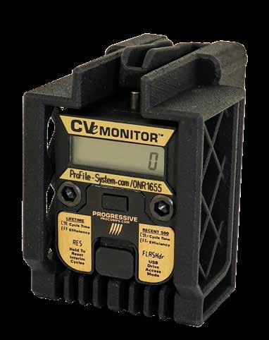
MOLD MONITORING F-11
CVe Monitor or CounterView pocket Bracket Installed PL 1.500 (38mm) 2.875 (78mm) 2.125 (54mm) 1.875 (48mm) 1.000 (26mm) 1.625 (41mm) CAD insertion point M Durethan
COVER PLATES
CATALOG NUMBER
DESCRIPTION
CVE-PLT CVe Monitor Cover Plate with (4) #8-32 x 5/16 long FHCS
CV-PLT CounterView Cover Plate with (4) #8-32 x 5/16 long FHCS
APPLICATION GUIDELINES
• Cover Plates can be used for both the A-Side and B-Side mounting options for the CounterViews sold separately on page F-8.
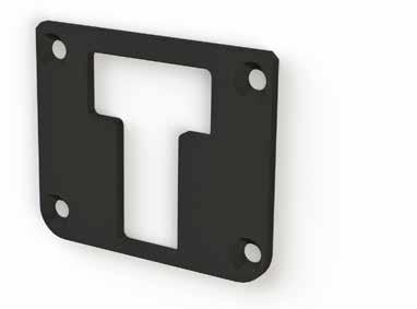
• CVe Monitors are sold separately on page F-1.
• The Cover Plates can be installed flush to the outside of the mold base by adjusting the depth of the pocket for the CVe Monitor or CounterView by the 1/8” thickness of the plate. If mounting on outside of the base, no pocket adjustment is needed.
MOLD
F-12
MONITORING
M 1018 H 135 Brinell S
2.375 2.000 2.375 2.000 .125 1.00 CV/CVe Depth 1/4 R (2) #8-32 FHCS (4) 1.500 .250 .250 2.000 1.500 2.000 PL CAD insertion point CVe Monitor Plate CounterView Plate
Black Oxide
MTWEB Features:
• Completely accessible from anywhere in the world as a mobile-friendly, secure, web-based system.
• A Mold Performance Dashboard is available from the main screen that shows the ongoing ratio of Scheduled vs. Unscheduled mold stops and also Top Mold Tooling costs and part quality defects.
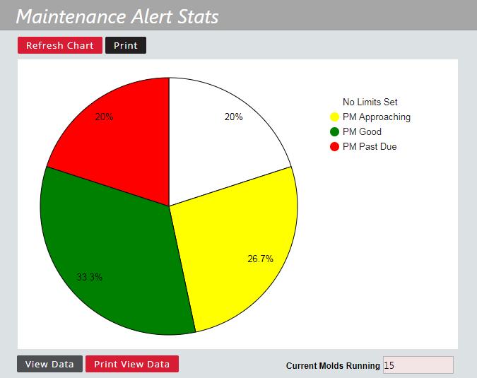
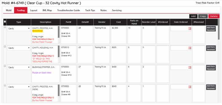
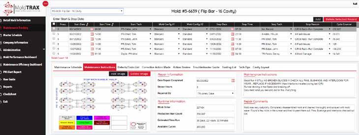
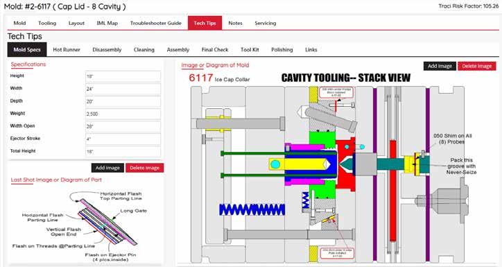
• Track all costs associated with individual or grouped molds, products, or mold frame styles.
• Comes preloaded with industry mold maintenance terms and explanations/descriptions in several important fields that can be edited/customized as the user requires.
• Many standard reports, specifically created for mold and maintenance tracking and cost analysis by entering the date range and selecting a report.
• Creates a baseline of data to set targets and goals and to measure continuous improvement.
• Includes a Maintenance Efficiency report for repair technician training.
• The contact database allows for entries of customers, vendors, and employees for easy accessibility.
• The PM Alert report shows what molds are running and proximity to a PM based on cycle counts that may be entered manually or electronically from many other systems.
• Link to images, videos and other external documentation instantly.
• All screens have been enlarged and many include Zoom windows with rich (customizable) text.
The Maintenance Tracking Section displays mold production run dates and times, press number and stop reasons, along with mold configuration changeovers.
An Inventory Monitoring feature has been added to allow the user to see how many components are left in stock, reorder amounts, and dates. Links can be added for quick ordering from your favorite component supplier. An Inventory Report may be run to monitor inventory and check the balance on hand of all components, in all molds.
System Requirements:
• Only needs a browser such as Google Chrome.
The Tech Tips section allows for critical bench procedures, techniques and special tools required to be documented, organized, and shared with tool room employees to keep repairs consistent and safe.
To Order:
• To order a copy of MTWEB or the MTWEB Upgrade, please call MoldTrax LLC at 1-419-281-0790 or email Steve@MoldTrax.com.
MOLD MONITORING F-13 MOLDTRAX ™ MOLD MAINTENANCE SOFTWARE
SYSTEM COOLING ™
System Cooling is a suite of products that allows injection molders and mold makers to collect and view data on the cooling lines within a mold and the cooling parameters during production. Molders utilizing the process monitoring system can view and collect data related to coolant flow, temperature, and pressure with information recorded and time stamped for historical tracking. Mold makers and tool room managers can utilize the Test Rig, a testing station that analyzes the mold for flow capacity, leaks, and optimal process set points.
Benefits:
• Allows for troubleshooting of quality inconsistencies.
• Alarms when process deviations are detected, reducing scrap.
• Reduces setup errors by the detection of flow constraints due to closed valves or dead-headed circuits.
• Identifies flow deviations from long-term corrosion build up, blockages, or equipment faults.
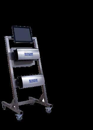
• Identifies temperature deviations and fluctuations from cycle time changes, unauthorized adjustments, or equipment faults.
• Validations certify that molds are production-ready.
SYSTEM COOLING ™ PROCESS MONITORING MANIFOLDS
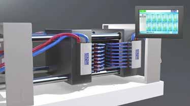

The instrumented manifold takes the place of traditional distribution manifolds on molding machines. Its compact form and stainless steel construction grants versatility in a variety of applications from harsh environments to spacelimited configurations and clean rooms. The flow sensors operate on the vortex flow principle without any moving parts. Manifolds can be mounted to the molding machine or a separate cart.
Manifolds monitor:
• Supply temperature
• Supply pressure
• Return temperature by zone
• Flow by zone
• Return pressure
Additional features include:
• Main supply and return ports on both top and bottom of manifold provide flexibility.
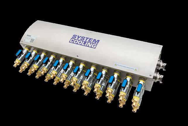
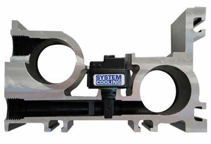
• No moving parts and large unrestricted flow path.
• Color-coded ball valves and 300 series connectors installed.
• Aids in scheduling maintenance intervals based on past analysis and historical data, while also providing reporting capabilities. Flow and temperature are measured in each zone individually.
Monitoring system consists of Manifolds and required electronics. Please contact Customer Service for system information and quotes.
MOLD MONITORING F-14
Monitor Validate Process ORDERING INFORMATION
ZONES FLOW RANGE MAX TEMPERATURE CATALOG NUMBER 4 .25-5.25 GPM / 1-20 LPM 200° F / 95° C SCM-4-1-SS 250° F / 120° C SCM-4-1-SS-HT .5-10.5 GPM / 2-40 LPM 200° F / 95° C SCM-4-2-SS 250° F / 120° C SCM-4-2-SS-HT 8 .25-5.25 GPM / 1-20 LPM 200° F / 95° C SCM-8-1-SS 250° F / 120° C SCM-8-1-SS-HT .5-10.5 GPM / 2-40 LPM 200° F / 95° C SCM-8-2-SS 250° F / 120° C SCM-8-2-SS-HT 12 .25-5.25 GPM / 1-20 LPM 200° F / 95° C SCM-12-1-SS 250° F / 120° C SCM-12-1-SS-HT .5-10.5 GPM / 2-40 LPM 200° F / 95° C SCM-12-2-SS 250° F / 120° C SCM-12-2-SS-HT
The System Cooling software interface is easy to use with only five screens to navigate. The system provides real-time information, historical data, and profiles (mold ID, circuit names, and data thresholds) for mold management:
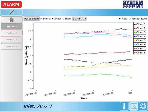
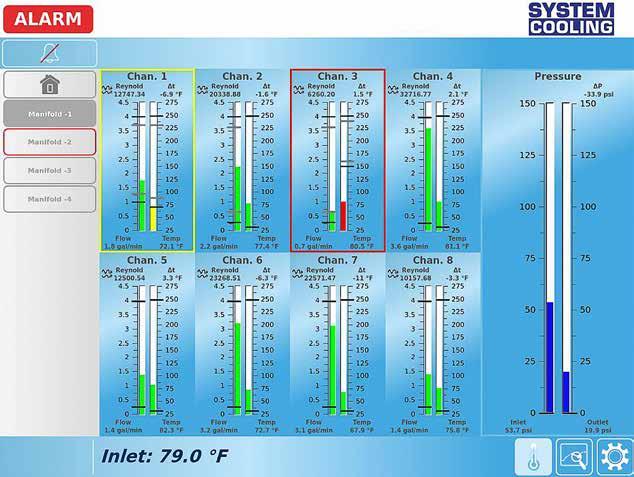

Information Display
• Temperature deltas between supply and return are calculated per zone.
• Reynolds numbers are calculated per zone, and laminar, transitional, or turbulent status is displayed.
• Alarms are activated per monitored parameter based on the profiles of the molds.
Historical Data
• Graphs present data for the most recent two hours of production.
• Data can be exported via USB or by network connection for viewing in Excel or additional systems.
System Overview
• The status of the entire system, all zones of all manifolds, can be viewed at a glance.

The System Cooling Monitoring System can either be permanently installed on a molding machine or mounted to a mobile cart as shown on the following page.
When mounted to a machine, the System Cooling I/O module, included with every system, can communicate to external devices such as the molding machine, part diverters, stack lights, and data networks.
• Alarm or warning state can switch molding machine to semi-auto or manual mode.
• Part diverters can automatically separate nonconforming parts.
• Illuminate stack lights for visibility to technicians.
• Data markers from the molding machine, typically at the beginning of each cycle, can be accepted and overlaid on the data.
• Machine idle state input signals the system to suppress alarm output during alarm state.
The system is also VNC capable, eliminating the need for a touchscreen controller. The interface can be accessed via VNC from a smartphone, laptop, or the machine controller.
Note: Molding presses must be verified for compatibility.
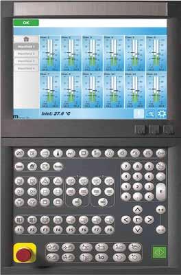
MOLD MONITORING F-15 SYSTEM COOLING ™ SOFTWARE
MOUNTING A B B C A C
SYSTEM COOLING ™ PORTABLE CART
As an alternative to permanently dedicating System Cooling to a press, the system can be mounted to a mobile cart. Applications that can benefit from a mobile cart include:
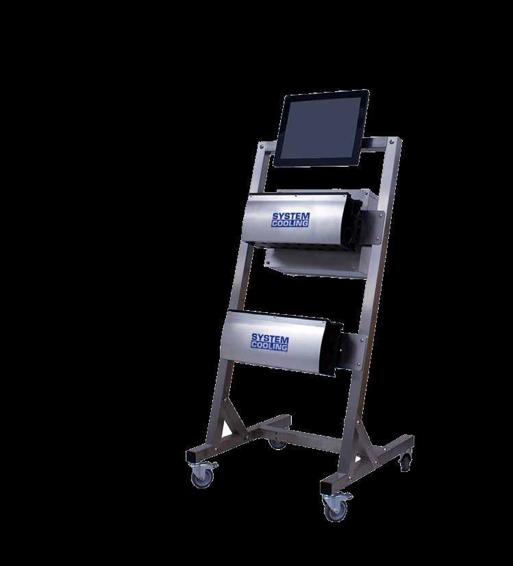
•
• Process development for new molds.
• Ad-hoc projects and validation efforts.
• On the standard carts, one or two manifolds can be mounted. Custom configurations are also available by contacting Customer Service.
Ordering Information
SYSTEM SPECIFICATIONS
MOLD MONITORING F-16
MANIFOLD SPECIFICATIONS Manifold Feed Ports 1” BSPP Circuit Ports 3/8 (-1) or 1/2 (-2) NPT Regulation Color-Coded Ball Valves Connections 300 Series Quick Connectors Maximum Pressure 145 PSI Maximum Temperature 200° F / 95° C (Std) 250° F / 120° C (High Temp) Flow Sensor Type Vortex Accuracy-Flow 1.5% fs Accuracy-Temperature +/- 1.5% fs Resolution-Temperature 0.9ºF/0.5ºC Response Time < 1 s Seals EPDM
Troubleshooting
CATALOG NUMBER TYPE SCP-CART Portable Cart for 4/8/12 Zone Manifolds SOFTWARE & ELECTRONICS SPECIFICATIONS Display 15.6” Touch Screen Communication Ports Ethernet / USB Communication system ASCII (USB)/HTML/SSH (optional)/VNC Supported Protocols USB Serial / TCP / IP Machine Controller Integration VNC Maximum Supported Manifolds 8 Manifolds / 96 Zones Display Units °C, LPM ,Bar / °F, GPM, PSI Alarm Units User Defined Warning Limits 10% of alarm limits (optional) Alarm & Warning Output N/C and N/O Dry Contacts Marker Input 24 VDC Galvanically Isolated Idle Input 24 VDC Galvanically Isolated Power Supply 12-24 VDC Contact tech@procomps.com for additional specifications or questions.
SYSTEM COOLING ™ TEST RIG
The Test Rig analyzes molds to validate, maintain, and optimize processes. The Rig runs flow capacity and pressure leak tests, and the premium version also determines optimal cooling process parameters. Reports are generated from the results and can be sent, saved, or printed. The Test Rig is a standalone test station equipped with a water reservoir, pump, 8-zone manifold, and unique control system and offered with three different models for customer applications.
New Molds
Mold makers are able to provide new tools to the customer complete with a report of operating parameters, including data relating to the cooling circuits in the mold. Traceable documentation of design validation for flow capacity under simulated production conditions and leak testing is provided by the Test Rig. These benchmarks are vital for any quality assurance process and establish a baseline for future comparisons.
Mold Maintenance
Mold cooling circuits need to be maintained regularly to remove scale and rust to ensure maximum productivity. With the Test Rig, the cooling channels can be analyzed and tested easily. The pressure can be precisely controlled by the variable output pump through the user interface to simulate the production environment. Each report can be compared against the baseline values to determine required maintenance and establish maintenance intervals for future service. The test results certify that a mold has regained flow capacity values and is in ready to run condition before being sent back to production.
Process Optimization

The cooling circuit flow capability at a given supply pressure is determined by the flow capacity test. The additional optimization executed by the extended flow test within the premium version determines the minimum required supply pressure to achieve maximum flow. This aids in defining process parameters to conserve central cooling supply capacity, potentially leading to reduced energy consumption.
Ordering Information
Specify the Test Rig catalog number above followed by the model suffix shown at right. Ex: SCTR-2-M will be the Test Rig Premium Model with the higher flow range.
Includes basic Test Rig features, plus:
• Advanced software with extended flow optimization test.
• Built-in WiFi router capable of sending reports directly to a printer
Includes the same features as the Plus model and adds:
• Automatic water change system

MOLD MONITORING F-17
CATALOG NUMBER FLOW RANGE SCTR-1-* 8 Zone Test Rig - .25-4 GPM / 1/15 LPM SCTR-2-* 8 Zone Test Rig - .5-10.5 GPM / 2-40 LPM MODEL TYPE FEATURES Test Rig Basic (-B)
Flow capacity and leak tests
Plug and play, ready for testing
Ports for data
networking Test Rig Plus (-P)
•
•
•
export or
Test Rig Premium (-M)
TEST RIG SPECIFICATIONS Zones 8 Regulation Color Coded Ball Valves Connections 300 Series Quick Connectors Flow Sensor Type Vortex Accuracy - Flow 1.5% fs Max Total Flow 32 GPM / 120 LPM Max Pump Pressure 85 PSI Max Rated Pressure 145 PSI Seals EPDM Display Units °C, LPM ,Bar / °F, GPM, PSI Ports Ethernet and USB Power Requirements 480v 60Hz 5A
ONLINE RESOURCES
When considering design options, numerous animations can be viewed at procomps.com/animations.
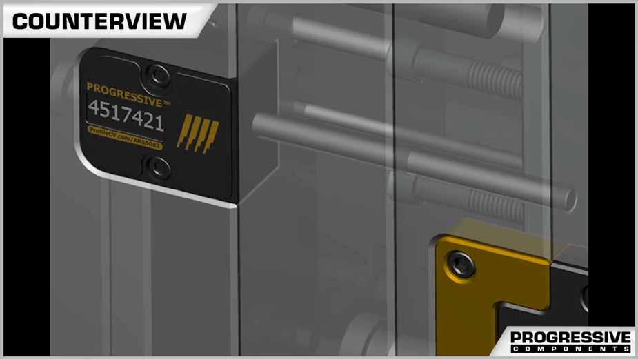
CAD geometry is available online as individual downloads or as part of the CADalog system. The seven formats include: IGES (.igs), ACIS (.sat), STEP (.step), Parasolid (.x_t), SolidWorks (.sldasm), NX (.prt) (Re-Use and MoldWizard) and Visi (.wkf).
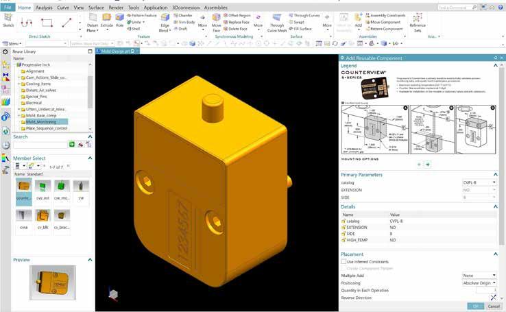
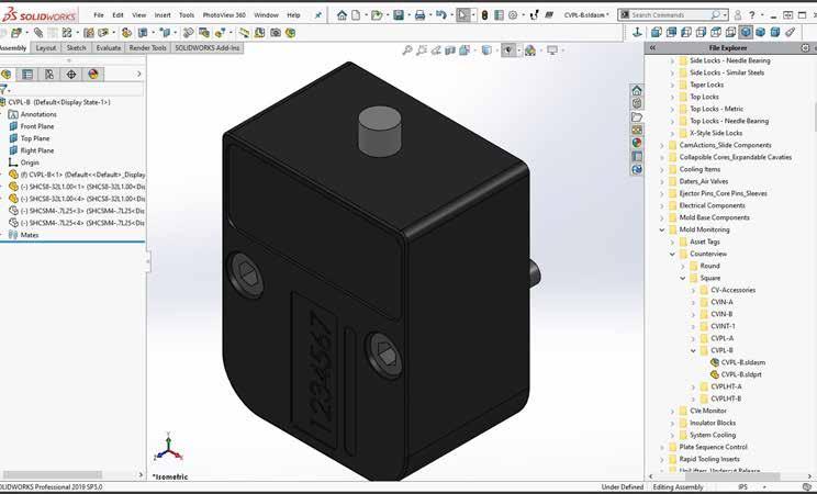
MOLD
F-18
MONITORING
Industry-leading web store expedites the purchasing process. Go to shop.procomps.com for information and additional resources.
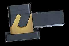
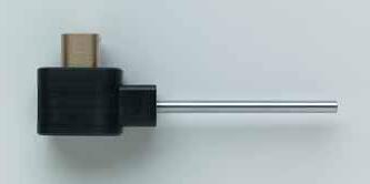
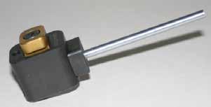
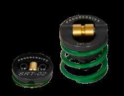
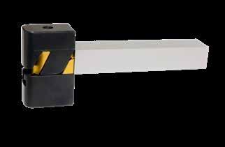
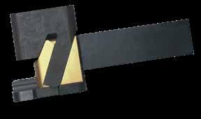
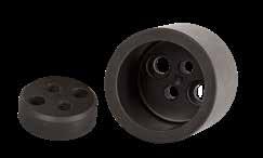
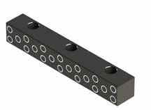
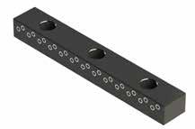
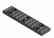
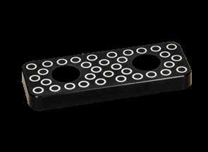
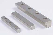
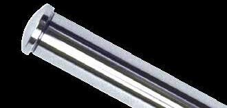
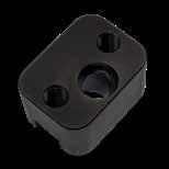
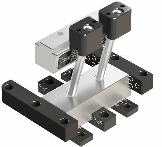
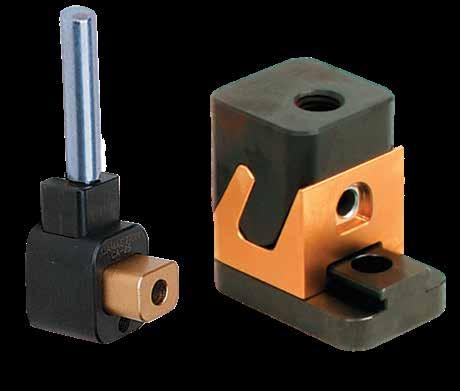
CamAction 100 Series CamAction 200 Series CamAction 250 Series CamAction 300/350 Series Prefix: CA, CAMM Prefix: CA, CAMM Prefix: CA Prefix: CA, CAMM Page: G-2 Page: G-3 Page: G-6 Page: G-5 - G-8
400 Series Slide Retainers & Cleats SRT Bases & Bushings Square Gibs Prefix: CA Prefix: SRT, SRTM Prefix: SG Page: G-13 Page: G-15 Page: G-18 Center Guides Wear Strips Wear Plates Bronze Wear Plates Prefix: CG Prefix: WS Prefix: WP Prefix: WP Page: G-19 Page: G-20 Page: G-21 Page: G-22 L-Gibs Angle Pins Angle Pin Holders Prefix: LGIB Prefix: AP Prefix: APH Page: G-22 Page: G-23 Page: G-24 & G-25
SLIDE COMPONENTS CAMACTIONS SECTION G
CamAction
CAM ACTION ® ASSEMBLIES SELECTION GUIDE
Progressive’s CamActions provide easy installation for molding and releasing details. Several sizes and travel configurations are available.
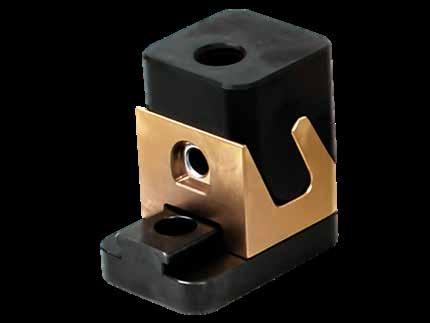
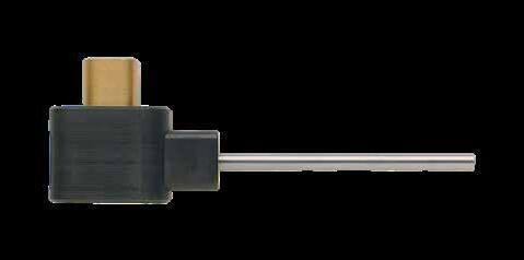
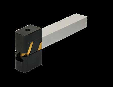
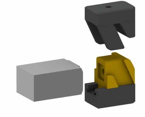
• Advanced materials and treatments for long-lasting production.
• Inserts and pins available in all series.
• For application assistance, please contact tech@procomps.com. Inch
SLIDE COMPONENTS, CAM ACTIONS G-1
TRAVEL OVERALL ASSEMBLY SIZES CATALOG NUMBER CAMACTION SERIES PAGE NUMBER .160" 1.00" X 1.25" X 1.00" H CA-100 100 Series G-2 .230" 1.00" X 1.25" X 1.50" H CA-200 200 Series G-3 .230" 1.00" X 1.25" X 4.12" H CA-200L* .150" .50” X .75” X 1.25” H CA-250-15 250 Series G-4 .310" .80" X 1.38" X 1.75" H CA-250-31 .500" 1.25” X 2.00” X 2.75” H CA-250-50 .250" 1.50" X 2.25" X 2.25" H CA-300 300 Series G-5 .250" 1.50" X 2.25" X 5.79" H CA-300L* .750" 1.50" X 2.63" X 2.63" H CA-350 350 Series G-7 1.000" 3.00" X 4.00" X 4.44" H CA-400 400 Series G-9 L= Longer Driver or Lock to extend below parting line. Metric Standard TRAVEL OVERALL ASSEMBLY SIZES CATALOG NUMBER CAMACTION SERIES PAGE NUMBER 4mm 26 X 32 X 25.4 H CAMM-100 100 Series G-2 5.8mm 26 X 32 X 38.1 H CAMM-200 200 Series G-3 5.8mm 26 X 32 X 103.2 H CAMM-200L* 4mm 12 X 20 X 32 H CAMM-250-4 250 Series G-4 8mm 20 X 34 X 47 H CAMM-250-8 12mm 32 X 50 X 68 H CAMM-250-12 6.35mm 40 X 60 X 57.7 H CAMM-300 300 Series G-6 6.35mm 40 X 60 X 147.4 H CAMM-300L* 18mm 40 X 64 X 66.5 H CAMM-350 350 Series G-8 L= Longer Driver or Lock to extend below parting line. Lock Slide Guide Insert
Standard
APPLICATION GUIDELINES
• Travel = .160” (4mm)
• Max operating temperature 300°F (150°C)
• Core Pins (sold on page G-10) are to be fully supported in the core as shown.
When the core pin is not shutting off on the inner core wall, the distance from the edge of the insert should be 1.142 for the slide carrier to shut off against the core insert.
When the core pin is not shutting off on the inner core wall, the distance from the edge of the insert should be 29.00 for the slide carrier to shut off against the core insert.
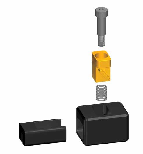
The .828 dimension must be maintained to avoid improper spring pre-load or damage to internal components.
The 21.03 dimension must be maintained to avoid improper spring pre-load or damage to internal components.
PART NAME
MATERIAL/TREATMENT
Driver H-13, 40-44 HRC, Titanium Nitride
Slide Carrier P-20, 30-34 HRC, Black Nitride
Housing 4140, 28-32 HRC, Black Nitride
SLIDE COMPONENTS, CAM ACTIONS G-2 CAM ACTION ® CATALOG NUMBER DESCRIPTION CA-100 CamAction Unit CAMM-100 Metric CamAction Unit .6250 .25 R .812 ±.010 1000 +.002 - .000 1.250 +.002 - .000 1 1870* 16.00 6 R 20 26 +.05 - .00 32 +.05 - .00 30.15* ±.25 828 ±.001 1000 .100 Allows .025 clearance below slide carrier Optional clearance for loading core pin #10 -24 thd 21.03 ±.025 25 2.5 Allows for .675 clearance below slide Optional clearance loading core M5x.8 thd
Inch Standard
Metric Standard
.6250 .25 R 1000 +.002 - .000 1.250 +.002 - .000 1 1870* 16.00 6 R 20 26 +.05 - .00 32 +.05 - .00 30.15* ±.25 828 ±.001 1000 Optional clearance for loading core pin #10 -24 thd 21.03 ±.025 25.4 2.5 Allows for .675 clearance below slide Optional clearance for loading core pin M5x.8 thd .6250 .25 R .010 1000 +.002 - .000 1.250 +.002 - .000 1 1870* 16.00 6 R 20 26 +.05 - .00 32 +.05 - .00 30.15* ±.25 828 ±.001 1000 clearance carrier Optional clearance for loading core pin #10 -24 thd 21.03 ±.025 25.4 2.5 Allows for .675 clearance below slide Optional clearance for loading core pin M5x.8 thd .6250 .25 R .812 ±.010 1000 +.002 - .000 1.250 +.002 - .000 1 1870* 16.00 6 R 20 26 +.05 - .00 32 +.05 - .00 30.15* ±.25 828 ±.001 1000 .100 Allows .025 clearance below slide carrier Optional clearance for loading core pin #10 -24 thd 21.03 ±.025 2 2.5 Allows for .675 clearance below slide Optional clearance loading core M5x.8 thd CAD insertion point
Housing
Spring Slide Carrier
Driver Shoulder Bolt
APPLICATION GUIDELINES
• Travel = .230” (5.8mm)
• Longer driver allows for extension below parting line up to 3” (76mm).

• Max operating temperature 480°F (250°C)
• Core Pins and Inserts (on page G-10) are to be fully supported in the core as shown.
When the core pin is not shutting off on the inner core wall, the distance from the edge of the insert should be 1.1425 for the slide carrier to shut off against the core insert.
When the core pin is not shutting off on the inner core wall, the distance from the edge of the insert should be 29.02 for the slide carrier to shut off against the core insert.
The .828 dimension must be maintained to ensure proper shut-off.
The 21.03 dimension must be maintained to ensure proper shut-off.
SLIDE COMPONENTS, CAM ACTIONS G-3 CAM ACTION .6250 R.25 .812 ±.010 1.000 +.002 - .000 1.250 +.002 - .000 1 1500* 16.00 R 6 20 ± .25 26 +.05 - .00 32 +.05 - .00 29.21* .2855 R .125 (2) R .187 (2) .7505 +.002 - .000 .571 +.002 - .000 1 1500* 7.25 R 3 (2) R 4 (2) 19.01 +.05 - .00 14.5 +.05 - .00 29.21* .828 ±.001 1000 .500 minus total insert preload .910 Optional clearance for loading core pin Optional clearance for loading core pin #10 -24 thd 1/4-20 thd 21.03 ±.025 25.4 12.7 minus total insert preload 23.11 M5-.8 thd M6-1 thd .6250 R.25 .812 ±.010 1000 +.002 - .000 1.250 +.002 - .000 1.1500* 16.00 R 6 20 ± .25 26 +.05 - .00 32 +.05 - .00 29.21* .2855 R .125 (2) R .187 (2) .7505 +.002 - .000 .571 +.002 - .000 1 1500* 7.25 R 3 (2) R 4 (2) 19.01 +.05 - .00 14.5 +.05 - .00 29.21* .828 ±.001 1000 .500 minus total insert preload .910 Optional clearance for loading core pin Optional clearance for loading core #10 -24 thd 1/4-20 thd 21.03 ±.025 25.4 12.7 minus total insert preload 23.11 M6-1 thd .6250 R.25 .812 ±.010 1000 +.002 - .000 1.250 +.002 - .000 1.1500* 16.00 R 6 20 ± .25 26 +.05 - .00 32 +.05 - .00 29.21* .2855 R .125 (2) R .187 (2) .7505 +.002 - .000 .571 +.002 - .000 1 1500* 7.25 R 3 (2) R 4 (2) 19.01 +.05 - .00 14.5 +.05 - .00 29.21* .828 ±.001 1000 .500 minus total insert preload .910 Optional clearance for loading core pin Optional clearance for loading core #10 -24 thd 1/4-20 thd 21.03 ±.025 25.4 12.7 minus total insert preload 23.11 M6-1 thd Inch Standard
Cavity Plan View Cavity Plan View Core Plan View .6250 R.25 .812 ±.010 1.000 +.002 - .000 1.250 +.002 - .000 1 1500* 16.00 R 6 20 ± .25 26 +.05 - .00 32 +.05 - .00 29.21* .2855 R .125 (2) R .187 (2) .7505 +.002 - .000 .571 +.002 - .000 1 1500* 7.25 R 3 (2) R 4 (2) 19.01 +.05 - .00 14.5 +.05 - .00 29.21* .828 ±.001 1000 .500 minus total insert preload .910 Optional clearance for loading core pin #10 -24 thd 1/4-20 thd 21.03 ±.025 25.4 12.7 minus total insert preload 23.11 M5-.8 thd M6-1 thd
Metric Standard
.6250 R.25 .812 ±.010 1000 +.002 - .000 1.250 +.002 - .000 1 1500* 16.00 R 6 20 ± .25 26 +.05 - .00 32 +.05 - .00 29.21* .2855 R .125 (2) R .187 (2) .7505 +.002 - .000 .571 +.002 - .000 1 1500* 7.25 R 3 (2) R 4 (2) 19.01 +.05 - .00 14.5 +.05 - .00 29.21* .828 ±.001 1000 .500 minus total insert preload .910 Optional clearance for loading core pin Optional clearance for loading core #10 -24 thd 1/4-20 thd 21.03 ±.025 25.4 12.7 minus total insert preload 23.11 M5-.8 thd M6-1 thd .6250 R.25 .812 ±.010 1000 +.002 - .000 1.250 +.002 - .000 1 1500* 16.00 R 6 20 ± .25 26 +.05 - .00 32 +.05 - .00 29.21* .2855 R .125 (2) R .187 (2) .7505 +.002 - .000 .571 +.002 - .000 1 1500* 7.25 R 3 (2) R 4 (2) 19.01 +.05 - .00 14.5 +.05 - .00 29.21* .828 ±.001 1000 .500 minus total insert preload .910 Optional clearance for loading core pin Optional clearance for loading core pin #10 -24 thd 1/4-20 thd 21.03 ±.025 25.4 12.7 minus total insert preload 23.11 M5-.8 thd M6-1 thd Core Plan View CATALOG NUMBER DESCRIPTION CA-200 CamAction Unit-Standard Driver CA-200L CamAction Unit-Longer Driver CAMM-200 Metric CamAction Unit-Standard Driver CAMM-200L Metric CamAction Unit-Longer Driver Driver Housing Slide Carrier CAD insertion point PART NAME MATERIAL/ TREATMENT Driver H-13, 40-44 HRC, Titanium Nitride Slide Carrier P-20, 30-34 HRC, Black Nitride Housing 4140, 28-32 HRC, Black Nitride
APPLICATION GUIDELINES
• Machine pockets from the common location “X” to the dimensions shown.
• Slide Retainers (SRT-10/SRTM-04) are installed in the slides on the CA-250-50/CAMM-250-12. Ball Plungers retain the slide in the other sizes.
• Max operating temperature 480°F (250°C).
• Inserts are sold separately on page G-11.
Socket Head Cap Screws (3) included.
Socket Head Cap Screws (3) included.
SLIDE COMPONENTS, CAM ACTIONS G-4
CATALOG NUMBER TRAVEL A POCKET B POCKET C MINIMUM CLEARANCE D MINIMUM CLEARANCE E POCKET F POCKET S1 ±.01 S2 ±.01 S3 ±.01 R POCKET RADIUS R2 THD CA-250-15 .15 .750 .500 .63 .60 .937 .313 .15 .59 .43 1/8 .03 #4-40 x 3/8 CA-250-31 .31 1.375 .800 1.03 1.03 1.375 375 .31 1.06 .75 3/16 .03 #8-32 x 7/16 CA-250-50 .50 2.000 1.250 1.50 1.90 2.125 .625 .37 1.62 1.12 1/4 .04 1/4-20 x 5/8 CATALOG NUMBER TRAVEL A POCKET B POCKET C MINIMUM CLEARANCE D MINIMUM CLEARANCE E POCKET F POCKET S1 ±.25 S2 ±.25 S3 ±.25 R POCKET RADIUS R2 THD CAMM-250-4 4 20 12 17 16 24 8 4 16 10 3 .4 M3-.5 x 10 CAMM-250-8 8 34 20 27 27 38 9 7 27 19 4 4 M4-.7 x 12 CAMM-250-12 12 50 32 39 38 53 15 10 40 27 5 1.0 M6-1 x 18 Cavity Plan View Core Plan View E Insert Height F* R2 D X X C THD A R R S1 S2 B THD (2) X S3 X A B Inch Standard Metric Standard
CAM ACTION ® 250 SERIES
E Insert Height F* R2 D X X C THD A R R S1 S2 B THD (2) X S3 X A B *Minus pre-load. CAD insertion point Lock Guide with Retainer Slide Insert PART NAME MATERIAL/ TREATMENT Lock H-13, 48-50 HRC, Black Nitride Slide H-13,
Titanium Nitride
H-13,
46-48 HRC,
Guide
48-50 HRC, Black Nitride
US Patent Nos. 7,229,269 & 7,431,581, with other patents issued and pending.
APPLICATION GUIDELINES
• Travel = .250”
• Each assembly includes SRT-10 Slide Retainer and (3) mounting screws.
• Max operating temperature 425°F (220°C).
• Core Pins and Inserts are sold separately on page G-12.
300 SERIES: INCH STANDARD
PART NAME MATERIAL/TREATMENT
Lock H-13, 40-44 HRC, Black Nitride
Slide H-13, 40-44 HRC, Titanium Nitride
Guide 4140, 28-32 HRC, Black Nitride
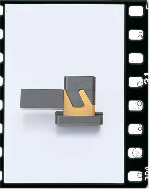
SLIDE COMPONENTS, CAM ACTIONS G-5 Lock Slide (with Slide Retainer) Insert Guide
1.625 .025 Clearance Pocket can be cleared in back of plate to allow for easy screw installation .875 Insert .437 Distance to SHCS center +.001 - .000 .625* R .03 +.001 - .000 X + .500 X Overall Length (4.90 max.) Machine this surface to suit .625* +.001 - .000 Lock Depth .289 Ref 1.187 Ref Pocket shown cleared X + .500 X CATALOG NUMBER DESCRIPTION CA-300 CamAction Unit-Standard Lock CA-300L CamAction Unit-Longer Lock *Minus pre-load. Core Plan View +.002 -.000 +.002 -.000 ±.005 X + .500 1.500 .750 .500 .25 R 1.500 3/8-16 x 5/8" Deep 2.250 1.125 .25 R .500 2.000 1.500 1/4-20 x 1/2" Deep X +.002 -.000 ±.005 ±.005 +.002 -.000 CAD insertion point
Cavity Plan View
US Patent Nos. 7,229,269 & 7,431,581, with other patents issued and pending.
300 SERIES: METRIC STANDARD
APPLICATION GUIDELINES
• Travel = 6.35mm
• Each assembly includes SRTM-04 Slide Retainer and (3) mounting screws. Core Pins and Inserts are sold separately on page G-12.
• Max operating temperature 425°F (220°C).
• See page G-5 for materials and treatments.
SLIDE COMPONENTS, CAM ACTIONS
CATALOG NUMBER DESCRIPTION CAMM-300 Metric CamAction Unit-Standard Lock CAMM-300L Metric CamAction Unit-Longer Lock Overall Length (124mm max.) Machine this surface to suit 16* +.025 - .000 Lock Depth 7.3 Ref 30.5 Ref Pocket shown cleared X + 14.12 X 41.6 .6 Clearance Pocket can be cleared in back of plate to allow for easy screw installation 22 Insert 11.11 Distance to SHCS center +.025 - .000 16* R .7 +.025 - .000 X + 14.12 X CAD insertion point 60 30 R 6.35 12 52 40 M6-1 x 12mm Deep X +.050 -.000 ±.127 ±.127 +.050 -.000 Core Plan View +.05 -.00 +.05 -.00 ± .12 X + 14.12 38 19 12 R 6.35 40 M10-1.5 x 20mm Deep Cavity Plan View Lock
Insert Guide
Slide (with Slide Retainer)
US Patent Nos. 7,229,269 & 7,431,581, with other patents issued and pending.
APPLICATION GUIDELINES
• Each assembly includes SRT-10 Slide Retainer and (3) mounting screws. Individual replacement parts are available.
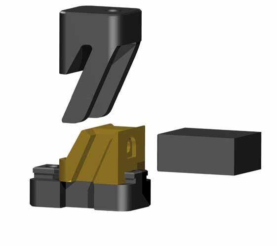
• Max operating temperature 425°F (220°C).
• Core Pins and Inserts are sold separately on page G-12.
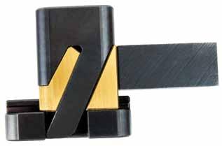
SLIDE COMPONENTS, CAM ACTIONS G-7
®
1.875 .03 Clearance Pocket can be cleared in back of plate to allow for easy screw installation .875 Insert .437 Distance to SHCS center +.001 - .000 .750* R .02 +.001 - .000 X + .250 X 1mm Clearance Pocket can be cleared in back of plate to allow for easy screw 22 Insert 20* R .5 +.02 *Minus pre-load. +.002 - .000 +.002 - .000 ±.005 X + .250 +.05 - .00 +.05 - .00 1.625 .812 .500 .25 R 1.500 3/8-16 x 5/8" Deep 40 7 R 40 M10-1.5 x 20 Deep 2.625 .25 R .437 2.312 1.500 1/4-20 x 1/2" Deep X +.002 - .000 ±.005 ±.005 +.002 - .000 64 7 R 12 54 40 M6-1 x 12 Deep X +.05 - .00 ±.1 ±.1 +.05 - .00 CATALOG NUMBER DESCRIPTION CA-350 CamAction Unit: 350 Series CAD insertion point PART NAME MATERIAL/TREATMENT Lock H-13, 40-44 HRC, Black Nitride Slide H-13, 40-44 HRC, Titanium Nitride Guide 4140, 28-32 HRC, Black Nitride Lock Slide (with Slide Retainer) Insert Guide Core Plan View Cavity Plan View • Travel = .750”
CAM ACTION
350 SERIES: INCH STANDARD
US Patent Nos. 7,229,269 & 7,431,581, with other patents issued and pending.
APPLICATION GUIDELINES
• Travel = 18mm
• Each assembly includes SRTM-04 Slide Retainer and (3) mounting screws.
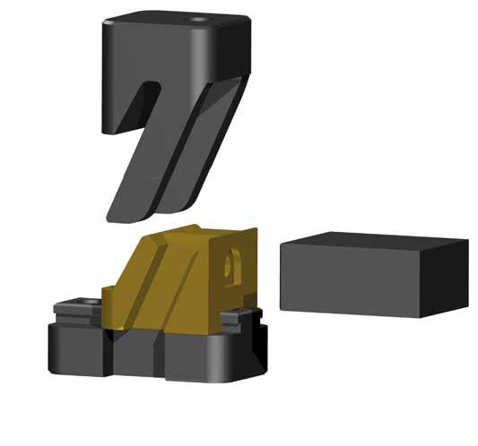
• Max operating temperature 425°F (220°C).
• Core Pins and Inserts are sold separately on page G-12.
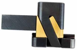
SLIDE COMPONENTS, CAM ACTIONS G-8 CAM ACTION ® 350 SERIES: METRIC STANDARD 46.5 1mm Clearance Pocket can be cleared in back of plate to allow for easy screw installation 22 Insert 11.4 Distance to SHCS center +.02 - .00 20* R .5 +.02 - .00 X + 6 X *Minus pre-load. .25 R .437 2.312 1.500 X ±.005 ±.005 +.002 - .000 64 7 R 12 54 40 M6-1 x 12 Deep X +.05 - .00 ±.1 ±.1 +.05 - .00 +.002 - .000 ±.005 X + .250 +.05 - .00 +.05 - .00 ±.1 X + 6 .500 .25 R 1.500 40 20 14 7 R 40 M10-1.5 x 20 Deep Core Plan View Cavity Plan View CATALOG NUMBER DESCRIPTION CAMM-350 CamAction Unit: 350 Series (Metric) PART NAME MATERIAL/TREATMENT Lock H-13, 40-44 HRC, Black Nitride Slide H-13, 40-44 HRC, Titanium Nitride Guide 4140, 28-32 HRC, Black Nitride CAD insertion point Lock Slide (with Slide Retainer) Insert Guide
US Patent Nos. 7,229,269 & 7,431,581, with other patents issued and pending.
400 SERIES: INCH STANDARD
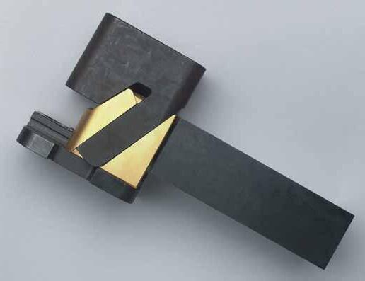
APPLICATION GUIDELINES
• Travel = 1.00”
• Max operating temperature 425°F (220°C).
• Each assembly includes an installed SRT-30 Slide Retainer, Threadless Waterline Plugs (2), O-Rings (2), and (4) mounting screws.
• Inserts are sold separately on page G-13.
above Parting Line (J)
Can be used with Extension Plugs or Connector Plugs
SLIDE COMPONENTS, CAM ACTIONS G-9
.437 X 4.000 2.000 +.002 - .000 ±.005 3.437±.005 1.500 3.000 +.002 - .000 .50 R 3/8-16 x 5/8" Deep Guide Pocket Insert Clearance Insert Bearing Clearance 1.437 Plus J Minus Preload Cavity is cleared for insert
Height
Application Above Parting Line .562 (4) .875 (4) 2.00 (approx. clr.) 1/8-27 NPT (In and Out) Front View X X + .500 Pocket Depth (Nom=3") Overall Stack Height of Assembly 1.500 1.437 Minus Preload 2.873 (Ref) .02 Max Radius on Pocket Core Plan View 3.000 1.500 .625 (2) +.002 - .000 +.002 - .000 3.500 1.125 .50 R 1/2-13 x 1" Deep X + .500 ±.005 ±.005 1.750 Cavity Plan View CATALOG NUMBER DESCRIPTION CA-400 CamAction Unit with 1” Travel CAD insertion point PART NAME MATERIAL/TREATMENT Lock H-13, 40-44 HRC, Black Nitride Slide H-13, 40-44 HRC, Titanium Nitride Guide 4140, 28-32 HRC, Black Nitride
US Patent Nos. 7,229,269 & 7,431,581, with other patents issued and pending.
CAM ACTION ACCESSORIES
100/200 SERIES CORE PINS
M M-2 H 60-62 HRC S Chrome Plated
APPLICATION GUIDELINES
• For use with 100 and 200 Series CamActions.
• When using with the 100 Series, 2˚ draft per side (minimum) is required in the molding area.
• Core Pin range shown above. Pins are keyed to fit into slot on slide carrier.
M M-2 H 60-62 HRC S Chrome Plated
For use with 200 Series CamActions only.
200 SERIES INSERTS
M P-20 Pre-Hard S Black Nitride
CSE2-62X75 .625 .750 .37
CSE2MM-16X19 15.98mm 19mm 9.5mm
For use with 200 Series CamActions only.
SLIDE COMPONENTS, CAM ACTIONS G-10
H D .343” (9mm) Max 1/4” (6mm) Diameter with Flats 3.00” (76mm) 61 ±1 HRC Y2 Y1 D H H W T 3.00" (76mm) .343 (8.73 mm) .343” (8.73 mm) 3.00” (76mm) +.002 -.000 +.05 mm -.00 mm [ [ 61 ± 1 HRC +.002 -.000 +.05 mm -.00 mm [ [ D H H W T 3.00" (76mm) .343” (8.73 mm) .343 (8.73 mm) 3.00” (76mm) +.001 -.000 +.025 mm -.000 mm +.001 -.000 [ [ +.025 mm -.000 mm [ [ 61 ±1 HRC 66 ±2 HRC 200 SERIES CORE PINS
CATALOG NUMBER D H Y1 Y2 CAP1-187 .1872 .1869 .37 .500 .750 CAP1-375 .3747 .3744 .37 .500 .688 CAPMM-5 4.984mm 4.992mm 9.5mm 12.7mm 19.05mm CAPMM-10 9.985mm 9.992mm 9.5mm 12.7mm 17.40mm CATALOG NUMBER D H CAP2-500 .5001 .5003 .37 CAP2MM-13 13.002mm 13.007mm 9.5mm
CATALOG NUMBER T W H
CAM ACTION ACCESSORIES 250 SERIES INSERTS
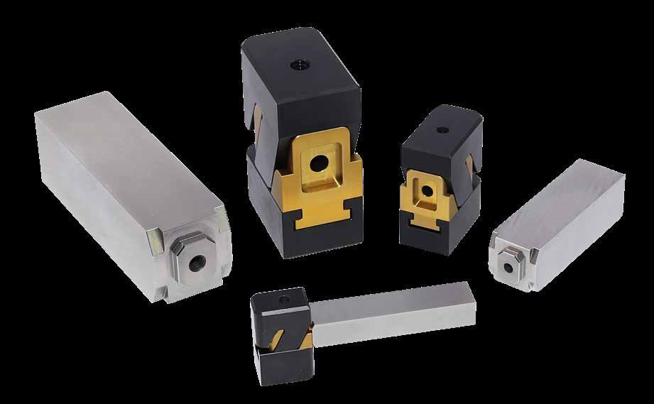
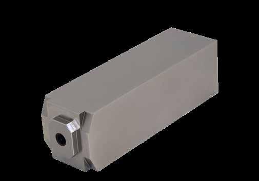
SLIDE COMPONENTS, CAM ACTIONS G-11
W THD H L C ASSEMBLY CATALOG NUMBER DC53 / 1.2360 CATALOG NUMBER H-13 / 1.2343 CATALOG NUMBER W +.000 -.001 H +.000 -.001 L C THD SOCKET HEAD CAP SCREW CA-250-15 CSE25P-15L2 CSE25H-15L2 500 .374 2.250 3/8 #4-40 x 1/2 CA-250-31 CSE25P-31L2.5 CSE25H-31L2.5 .800 749 2.500 1/2 #8-32 x 7/8 CA-250-50 CSE25P-50L4 CSE25H-50L4 1.250 1.249 4.000 3/4 1/4-20 x 1-1/4 ASSEMBLY CATALOG NUMBER DC53 / 1.2360 CATALOG NUMBER H-13 / 1.2343 CATALOG NUMBER W +.00 -.03 H +.00 -.03 L C THD SOCKET HEAD CAP SCREW CAMM-250-4 CSE25MMP-4L60 CSE25MMH-4L60 12 10 60 8 M3 -.5 x 12 CAMM-250-8 CSE25MMP-8L80 CSE25MMH-8L80 20 20 80 11 M4 -.7 x 22 CAMM-250-12 CSE25MMP-12L100 CSE25MMH-12L100 32 29 100 15 M5-.8 x 30 Inch Standard Screw included. Screw included. Metric Standard M DC53 / 1.2360 H 58-62 HRC M H-13 / 1.2343 H 48-52 HRC M DC53 / 1.2360 H 58-62 HRC M H-13 / 1.2343 H 48-52 HRC
CAM ACTION ACCESSORIES
H 58-62 HRC S Chrome Plated
Socket Head Cap Screw included.
300 SERIES INSERTS
300 SERIES UL ADAPTERS
SLIDE COMPONENTS, CAM ACTIONS G-12
SERIES
THD D 6.00" (152mm) C Notched for orientation +.010 - .000 L L W H +.002 - .000 +.05 mm - .00 mm [ [ THD C +.002 - .000 +.05 mm - .00 mm [ [ +.010 - .000 +.25 mm - .00 mm [ [ D THD T +.000 - .005 +.00 - .12 W +.000 - .005 +.00 - .12 H +.000 - .002 +.00 - .05 [ [ [ [ [ [ UL Adapter U-Coupling Core Blade .30 (8mm) Add .0015 (.04mm) to Core Blade diameter or T & W dimensions for clearance C B A +.000 -.002 +.00 -.05
300/350
CORE PINS
CATALOG NUMBER T W H D THD A B C COMPATIBLE U-COUPLING CTG-300 .875 .875 .563 .098 1/4-20 x 7/8 .75 .406 1.187 UCU87 CTGMM-300 23 mm 23 mm 6 mm 2.5 mm M6-1 x 22 12 mm 10 mm 30.15 mm UCMM22 Socket Head Cap Screw included. UniLifter Core Blades and U-Couplings are sold in section H.
CATALOG NUMBER D THD C CAP3-750 .7504 .7508 1/4-20 x 7/8 3/4 CAP3MM-19 19.009mm 19.019mm M6-1 x 20 20mm
M-2
CATALOG NUMBER H W L THD C CSE3-50 .875 1.500 .50 1/4-20 x 7/8 5/8 CSE3-200 .875 1.500 2.00 1/4-20 x 7/8 5/8 CSE3MM-12 22mm 38mm 12mm M6-1 x 20 15mm CSE3MM-50 22mm 38mm 50mm M6-1 x 20 15mm Socket Head Cap Screw included.
S Salt Bath Nitride
M
M P-20 Pre-Hard S Salt Bath Nitride M 4140
SLIDE COMPONENTS, CAM ACTIONS G-13
INSERTS +.001 -.000 Insert bearing area .500 2.500 .025 Clear. Bearing area should be at least 1.25" (1/4" over travel distance) Insert Length 3.000 .875 (4) .25 1.0" Locating 1/2-13 Thread +.002 -.000 +.03 -.00 6.000 .562 (4) 68 ±2 HRC 30 ±2 HRC CATALOG NUMBER DESCRIPTION CSE4-18X30 CA-400 Insert 1/2-13 x 1-3/4 Socket Head Cap Screw included. 3.000 .875 (4) .25 1.0" Square Locating Pad 1/2-13 Thread +.002 -.000 +.03 -.00 6.000 1.875 +.002 -.000 .562 (4) 68 ±2 HRC CAD insertion point M P-20 Pre-Hard S Salt Bath Nitride (SBN)
CAM ACTION ACCESSORIES 400 SERIES
SLIDE RETAINERS
Progressive’s SRT® Series Slide Retainers reliably hold from 2 to 80 pounds (1 to 36 kgs) each. This slide retention design now features color-coded springs to indicate force rating. This compact design allows for installation in a mold base or wear plates.
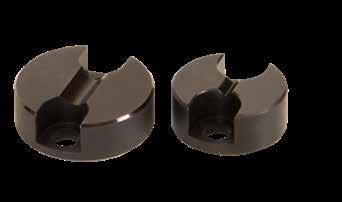
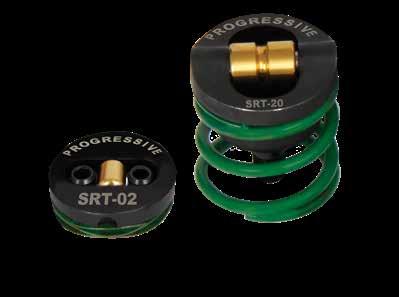
Optional cleats may be selected or the V-Groove for roller retention may be machined in the bottom of the slide as shown on page G-15.
Cleats sold separately.
COMPONENTS, CAM
G-14
SLIDE
ACTIONS
SLIDE RETAINERS CLEATS SLIDE RETAINER CATALOG NUMBER MAX WEIGHT PER UNIT (LBS) D +.005 -.000 L ±.001 S ±.002 T SCREWS (2) E MINIMUM THREAD DEPTH COLOR CLEAT CATALOG NUMBER G ±.001 C ±.002 H SCREWS (2) J MINIMUM THREAD DEPTH SRT-02 2 .625 .160 .155 #4-48 .075 GRN SRTC-10 .250 .190 #6-32 .250 SRT-04 4 BLU SRT-10 10 RED SRT-20 20 .750 .500 .150 #8-32 .190 GRN SRTC-30 . 250 .250 #6-32 .250 SRT-30 30 BLU SRT-50 50 .875 .750 .150 #8-32 .245 RED SRTC-80 . 250 .300 #6-32 .250 SRT-80 80 YEL SRT-40 40 1.125 .856 .205 1/4-20 .480 BLU SRTC-75 .250 .400 #6-32 .250 SRT-60 60 RED SRT-75 75 YEL US Patent Nos. 7,229,269 & 7,431,581, with other patents issued and pending. Metric Standard SLIDE RETAINERS CLEATS SLIDE RETAINER CATALOG NUMBER MAX WEIGHT PER UNIT (LBS) D +.1 -.0 L ±.025 S ±.05 T SCREWS (2) E MINIMUM THREAD DEPTH COLOR CLEAT CATALOG NUMBER G ±.025 C ±.05 H SCREWS (2) J MINIMUM THREAD DEPTH SRTM-01 1 15.9 4.06 3.95 M3 - .5 1.9 GRN SRTMC-04 6.35 4.85 M3 - .5 6.35 SRTM-02 2 BLU SRTM-04 4 RED SRTM-09 9 19.1 12.70 3.80 M4 - .7 4.8 GRN SRTMC-13 6.35 6.35 M3 - .5 6.35 SRTM-13 13 BLU SRTM-22 22 22.3 19.05 3.80 M4 - .7 6.2 RED SRTMC-36 6.35 7.60 M3 - .5 6.35 SRTM-36 36 YEL SRTM-18 18 28.2 21.75 5.20 M6 - 1.0 12.0 BLU SRTMC-34 6.35 10.50 M3 - .5 6.35 SRTM-28 28 RED SRTM-34 34 YEL SRT-20 SLIDE 20 LBS. SLIDE SRT-30 60 LBS.
the single Slide Retainer to
the slide weight.
force
Slide Retainers to
the slide weight. Inch Standard
Select
match
Or add the
of multiple
match
H ØD .01 x 45˚ (2) L T G J E S Do not chamfer screw threads OPTIONAL CLEAT SLIDE RETAINER C Cleat SRT-20 SLIDE 20 LBS. SLIDE SRT-30 SRT-30 60 LBS. Roller: M M-2 H 60-62 HRC S Titanium Nitride Coated 80 HRC M 4140 H 50-54 HRC S Black Oxide M 4140 H 50-54 HRC S Black Oxide Roller: M M-2 H 60-62 HRC S Titanium Nitride Coated 80 HRC
sold separately. CAD insertion point
Cleats
APPLICATION GUIDELINES
• Maximum operating temperature is 425°F (220°C).
• Match total Slide Retainers Spring force to slide weight; excess spring force could induce wear.
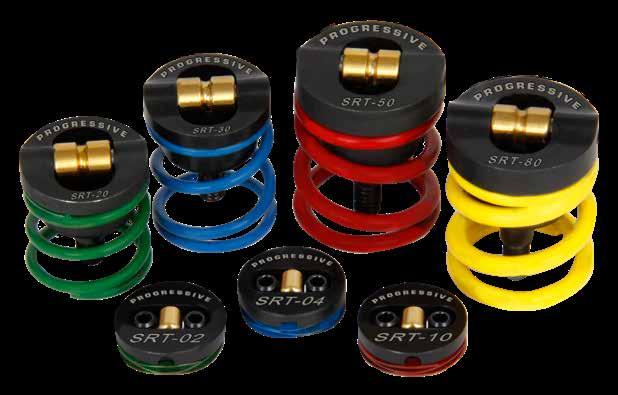
• Do not chamfer screw threads.
• Machine 10° lead-in on all slides to aid in assembly once the SRT is installed.
• Optional Bases and Bushings shown on the following page allow for installation in plates made from materials such as aluminum, copper, and bronze and contain the screw/thread installation.
SLIDE COMPONENTS, CAM ACTIONS G-15 SLIDE RETAINERS US Patent Nos. 7,229,269 & 7,431,581, with other patents issued and pending. RETAINER CATALOG NUMBER T THREAD (2) TAP CLASS REQUIRED K V-GROOVE A 10° ANGLE LEAD - IN SRT-02 #4-48 2B GH2 .041" .02" SRT-04 SRT-10 SRT-20 #8-32 2B GH3 .078" .04" SRT-30 SRT-50 #8-32 2B GH3 .078” .05” SRT-80 SRT-40 1/4-20 2B GH3 .102” .07” SRT-60 SRT-75 SRTM-01 M3 - .5 6H D3 1 mm .50 mm SRTM-02 SRTM-04 SRTM-09 M4 - .7 6H D4 2 mm 1.00 mm SRTM-13 SRTM-22 M4 - .7 6H D4 2 mm 1.27 mm SRTM-36 SRTM-18 M6 - 1.0 6H D4 2.6 mm 1.85 mm SRTM-28 SRTM-34 NO CHAMFER T 90° K A 10° A 10°
SLIDE RETAINERS BASES & BUSHINGS
SRT BASES
SRT Bases enable the Slide Retainer to be installed in a hardened plate when mold base steel is aluminum, for example. (SRTBA-10 shown in graphics.)
SRT Bushings accept the standard Slide Retainer to allow for installation in soft materials (aluminum, copper bronze, etc). Also, the SRT Bushing can provide hardened guidance against wear rather than bearing on a bronze wear plate. (SRTBU-30 shown in graphics.)
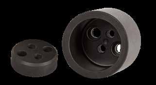
SLIDE COMPONENTS, CAM ACTIONS G-16
US Patent Nos. 7,229,269 & 7,431,581, with other patents issued and pending. CATALOG NUMBER D +.005 -.000 L ±.001 S1 ±.01 T E REF SCREWS (2) USE WITH CATALOG NUMBER D +.001 -.000 L +.002 -.000 S1 ±.01 T E REF SCREWS (2) SRTBA-10 .625 .375 .37 .215 .220 #4-40 x 5/16 SRT-02 SRTBU-10 .875 .375 .37 .215 .220 #4-40 x 5/16 SRT-04 SRT-10 SRTBA-30 .750 .750 .44 .250 .280 #6-32 x 3/8 SRT-20 SRTBU-30 1.000 .750 .44 .250 .280 #6-32 x 3/8 SRT-30 SRTBA-80 .875 1.000 .50 .250 .280 #6-32 x 3/8 SRT-50 SRTBU-80 1.125 1.000 .50 .250 .280 #6-32 x 3/8 SRT-80 SRTBA-75 1.125 1.300 .62 .443 .380 #10-32 x 1/2 SRT-40 SRTBU-75 1.500 1.300 .62 .443 .380 #10-32 x 1/2 SRT-60 SRT-75 SRT BUSHINGS L T ØD S1 CENTERED Screws E S1 CENTERED Screws E L T ØD
CATALOG NUMBER D +.1 -.0 L ±.03 S1 ±.25 T E REF SCREWS (2) USE WITH CATALOG NUMBER D +.03 -.00 L +.05 -.00 S1 ±.25 T E REF SCREWS (2) SRTMBA-04 15.9 9.56 8 5.50 5.30 M2.5-.45 x 8 SRTM-01 SRTMBU-04 22.3 9.50 8 5.44 5.35 M2.5-.45 x 8 SRTM-02 SRTM-04 SRTMBA-13 19.1 19.05 11 6.35 4.95 M3-.5 x 8 SRTM-09 SRTMBU-13 25.4 19.10 11 6.35 4.95 M3-.5 x 8 SRTM-13 SRTMBA-36 22.3 25.40 13 6.35 4.95 M3-.5 x 8 SRTM-22 SRTMBU-36 28.5 25.40 13 6.35 4.95 M3-.5 x 8 SRTM-36 SRTMBA-34 28.2 33.00 16 11.25 9.90 M5-.8 x 12 SRTM-18 SRTMBU-34 37.0 33.00 16 11.25 9.90 M5-.8 x 12 SRTM-28 SRTM-34
Inch Standard CAD insertion point Base: M D-2 H 58-60 HRC Bushing: M D-2 H 58-60 HRC Metric Standard Base: M D-2 H 58-60 HRC Bushing: M D-2 H 58-60 HRC
SIDE ACTION COMPONENTRY OVERVIEW
Progressive’s Square Gibs, Center Guides, and Wear Strips are designed to be modified to suit the mold design, providing a range of lengths from 2” to 13.5” long. In addition, Angle Pins and Angle Pin Holders allow for removal from parting line.
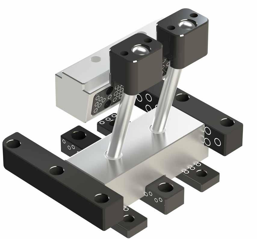
Angle Pin Holders (Page G-24)
Angle Pins (Page G-23)
Wear Strips (Page G-20)
Center Guides (Page G-19)
APPLICATION GUIDELINES
• On the Gibs, Guides, and Wear Strips, the tool maker can cut off one or both ends of the products or create two symmetrical parts.
• Vertical lines in the image below identify the 1/4” increments where the Square Gib can be cut as an example, and this method can be applied to the Center Guides and Wear Strips. Corner radii can also be added by the tool maker.
• Mold-Ready Options: Progressive can provide the Center Guides and Square Gibs cut-to-length with or without corner radii. Refer to the individual pages to follow for information on how to order.
SLIDE COMPONENTS, CAM ACTIONS G-17
.343 (8.73 mm)
Radius
4.25 Long Gib/Guide
Radius Radius Original Gib/Guide 10” Length
4.25 Long Gib/Guide
Square Gibs (Page G-18)
APPLICATION GUIDELINES
• Square Gibs are designed to be cut-to-length to make two Gibs out of one bar.
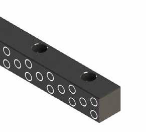
• The maximum heel size for each Square Gib is shown at right.
MOLD-READY GIBS
To Order:
Start wtih the prefix and the size from above. Example: SG75
• For Gibs with no radii and cut-to-length, specify the length (CTL). Example: SG75L4.25
• For 1 corner radius as shown below left, specify the length followed by the 1R designation and then the required pocket radius. (The actual radius will be larger for clearance.) Example: SG75L4.25-1R.312
• For 2 corner radii as shown below right, specify the length followed by the 2R designation and then the required pocket radius. (The actual radii will be the same and will be larger for clearance.) Example: SG75L4.25-2R.312
• Submit the item number and quantity to Customer Service for a quotation.
Note: Screw sizes and locations will be the same as the standard Gibs. Any specifications outside of the modifications above can be quoted made-to-order by contacting tech@procomps.com.
SLIDE COMPONENTS, CAM ACTIONS G-18
CATALOG NUMBER W +.0005 - .0000 H +.000 - .005 L ±..005 NUMBER OF SCREW HOLES Z CHAMFER S1 ±.01 S2 ±.01 S3 ±.01 S4 ±.01 SHCS SG50L6 .502 .495 6.00 4 .03 .75 2.25 .18 #8-32 x 1/2 SG50L10.5 10.50 6 .88 2.63 4.38 SG75L10 .752 .745 10.00 4 .04 1.25 3.75 .25 1/4-20 x 7/8 SG75L13.5 13.50 6 1.13 3.38 5.63 SG100L10 1.002 .995 10.00 4 .04 1.25 3.75 .37 5/16-18 x 1-1/8 SG100L13.5 13.50 6 1.13 3.38 5.63 W H SHCS Heel Z L S3 S2 S4 S1 M H-13 H Core: 42-48 HRC, Surface: 70 HRC S Black Nitride CAD insertion point
SQUARE GIBS
CTL R Length specified by customer. R CTL R Length specified by customer. R R R R CTL R Length specified by customer. CTL R Length specified by customer. W H SHCS Heel L S3 S2 S1 SIZE HEEL SG50 .125 SG75 .250 SG100 .312
Screws included.
To Order:
Start wtih the prefix and the size from above. Example: CG50X62
MOLD-READY GUIDES
• For Guides with no radii and cut-to-length, specify the length (CTL). Example: CG50X62L4.25
• For 2 corner radii as shown below left, specify the length followed by the 2R designation and then the required pocket radius. (The actual radius will be larger for clearance.) Example: CG50X62L4.25-2R.312
• For 4 corner radii as shown below right, specify the length followed by the 4R designation and then the required pocket radius. (The actual radii will be the same and will be larger for clearance.) Example: CG50X62L4.25-4R.312
• Submit the item number and quantity to Customer Service for a quotation.
Note: Screw sizes and locations will be the same as the standard Guides. Any specifications outside of the modifications above can be quoted made-to-order by contacting tech@procomps.com.
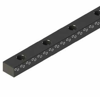
SLIDE COMPONENTS, CAM ACTIONS G-19 CATALOG NUMBER W +.0000 - .0005 H +.000 - .005 L ±.005 NUMBER OF SCREW HOLES S1 ±.01 S2 ±.01 S3 ±.01 SHCS CG50X62L6 .4998 620 6.00 4 .75 2.25 #8-32 x 3/4 CG50X62L10.5 10.50 6 .88 2.63 4.38 CG75X62L10 .7498 620 10.00 4 1.25 3.75 1/4-20 x 3/4 CG75X62L13.5 13.50 6 1.13 3.38 5.63 CG100X75L10 .9998 .745 10.00 4 1.25 3.75 5/16-18 x 7/8 CG100X75L13.5 13.50 6 1.13 3.38 5.63 L W H S3 S2 S1 SHCS .02 x 45° .04 x 45° M H-13 H Core: 42-48 HRC, Surface: 70 HRC S Black Nitride CAD insertion point Screws included.
CTL R Length specified by customer. R CTL R Length specified by customer. R R R R CTL R Length specified by customer. CTL R Length specified by customer. CENTER GUIDES
WEAR STRIPS
APPLICATION GUIDELINES
• Wear Strips can be cut to use in multiple areas and can be used in tandem with other Z-Series products as shown in the graphic below.
• For finish-machined Wear Plate options, refer to page G-21.
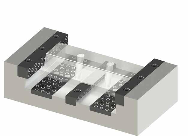
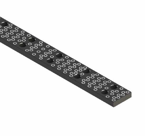
SLIDE COMPONENTS, CAM ACTIONS G-20 CATALOG NUMBER W +.000 - .002 L ±.005 NUMBER OF SCREW HOLES S1 ±.01 S2 ±.01 S3 ±.01 S4 ±.01 WS75L6 .749 6.00 4 .75 2.25 WS75L10.5 10.50 6 .88 2.63 4.38 WS100L10 .999 10.00 4 1.25 3.75 WS100L13.5 13.50 6 1.13 3.38 5.63 WS150L10 1.499 10.00 8 1.25 3.75 .375 WS150L13.5 13.50 12 1.13 3.38 5.63 WS200L10 1.999 10.00 8 1.25 3.75 .500 WS200L13.5 13.50 12 1.13 3.38 5.63 S4 W L S3 S2 S1 1/4-20 SHCS .382 +.002 -. 000 M H-13 H Core: 42-48 HRC, Surface: 70 HRC S Black Nitride CAD insertion point 1/4-20 x 1/2” long screws included.
APPLICATION GUIDELINES
• Standardized design is ready to install.
• Wear Plates can be cut as long as the edges have radii.
• Low Head Cap Screws included.
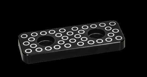
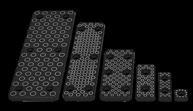
SLIDE COMPONENTS, CAM ACTIONS G-21
CATALOG NUMBER W +.000 - .005 L +.000 - .005 S1 ±.01 R POCKET RADIUS LHCS WP050X250 .500 2.500 .87 .094 #8-32 x 3/8 WP050X350 3.500 1.37 WP075X400 .750 4.000 1.50 .125 #10-32 x 3/8 WP075X600 6.000 2.50 CATALOG NUMBER W +.000 - .005 L +.000 - .005 S1 ±.01 R POCKET RADIUS LHCS WP050X150 .500 1.500 .37 .094 #8-32 x 3/8 WP075X200 .750 2.000 .50 .125 #10-32 x 3/8 CATALOG NUMBER W +.000 - .005 L +.000 - .005 S1 ±.01 S2 ±.01 R POCKET RADIUS LHCS WP125X300 1.250 3.000 1.00 .37 .187 #10-32 x 3/8 WP125X500 1.250 5.000 2.00 .37 WP125X800 1.250 8.000 3.50 .37 WP200X600 2.000 6.000 2.50 .62 WP200X800 2.000 8.000 3.50 .62 WP250X600 2.500 6.000 2.50 .75 WP300X600 3.000 .250±.0005 L W R .04 x 45° L W S1 R .250±.0005 .04 x 45° W L S1 R .250±.0005 .04 x 45° W L R S1 S2 .250±.0005 .04 x 45° CATALOG NUMBER W +.000 - .005 L +.000 - .005 R POCKET RADIUS LHCS WP050X050 .500 .500 .125 #8-32 x 3/8 M H-13 H Core: 42-48 HRC, Surface: 70 HRC S Black Nitride M H-13 H Core: 42-48 HRC, Surface: 70 HRC S Black Nitride CAD insertion point M H-13 H Core: 42-48 HRC, Surface: 70 HRC S Black Nitride M H-13 H Core: 42-48 HRC, Surface: 70 HRC S Black Nitride
WEAR PLATES
BRONZE WEAR PLATES
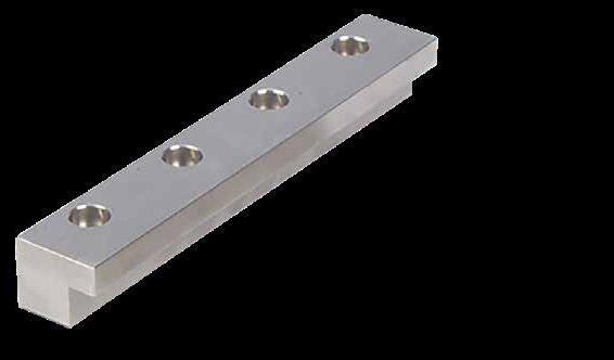
L-GIBS
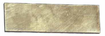
SLIDE COMPONENTS, CAM ACTIONS G-22
T W L=4” L=5” L=6” L=8” L=10” L=12” 1/4 1.000 WP25X1X4 WP25X1X5 WP25X1X6 WP25X1X8 WP25X1X10 WP25X1X12 1.500 WP25X1.5X4 WP25X1.5X5 WP25X1.5X6 WP25X1.5X8 WP25X1.5X10 WP25X1.5X12 2.000 WP25X2X4 WP25X2X5 WP25X2X6 WP25X2X8 WP25X2X10 WP25X2X12 2.500 WP25X2.5X4 WP25X2.5X5 WP25X2.5X6 WP25X2.5X8 WP25X2.5X10 WP25X2.5X12 3.000 WP25X3X4 WP25X3X5 WP25X3X6 WP25X3X8 WP25X3X10 WP25X3X12 4.000 WP25X4X4 WP25X4X5 WP25X4X6 WP25X4X8 WP25X4X10 WP25X4X12 3/8 1.000 WP37X1X4 WP37X1X5 WP37X1X6 WP37X1X8 WP37X1X10 WP37X1X12 1.500 WP37X1.5X4 WP37X1.5X5 WP37X1.5X6 WP37X1.5X8 WP37X1.5X10 WP37X1.5X12 2.000 WP37X2X4 WP37X2X5 WP37X2X6 WP37X2X8 WP37X2X10 WP37X2X12 2.500 WP37X2.5X4 WP37X2.5X5 WP37X2.5X6 WP37X2.5X8 WP37X2.5X10 WP37X2.5X12 3.000 WP37X3X4 WP37X3X5 WP37X3X6 WP37X3X8 WP37X3X10 WP37X3X12 4.000 WP37X4X4 WP37X4X5 WP37X4X6 WP37X4X8 WP37X4X10 WP37X4X12 T ±.001 W ±.01 L +1/8 - 0
CATALOG NUMBER W +.002 -.000 L +.125 -.000 H ±.005 A +.002 -.000 B +.002 -.000 NUMBER OF SCREW HOLES SHCS S1 ±.01 S2 ±.01 S3 ±.01 D LGIB75L5.25 .750 5.25 .750 .312 .563 3 1/4 1.62 .281 LGIB75L8.75 .750 8.75 .750 .312 .563 4 1/4 1.00 3.37 .281 LGIB100L6 1.000 6.00 .750 .375 .750 4 5/16 .75 2.25 .375 LGIB100L10 1.000 10.00 .750 .375 .750 4 5/16 1.25 3.75 .375 LGIB125L6 1.250 6.00 .875 .500 .875 4 3/8 .75 2.25 .438 LGIB125L10 1.250 10.00 .875 .500 .875 4 3/8 1.25 3.75 .438 LGIB150L9 1.500 9.00 1.250 .750 1.000 4 3/8 1.12 3.37 .500 LGIB150L15 1.500 15.00 1.250 .750 1.000 6 3/8 1.25 3.75 6.25 .500 A H W B D S2 S1 S3 L SHCS CAD insertion point M CA954 Solid Bronze H 170 Brinell M CA954 Solid Bronze H 170 Brinell To Order Undrilled L-Gibs: • Specify “N” at the end of the catalog number. Example: LGIB150L9N.
To Order:
• A full radius option can be ordered by specifying the prefix of “APR” and the diameter as outlined above, plus “L” and the length required.
• Example: APR625L7.244 (no dashes/spaces) is an Angle Pin with a 5/8” diameter machined to 7.244” long with a full radius.
• Note: P will be 1.25” per table above.
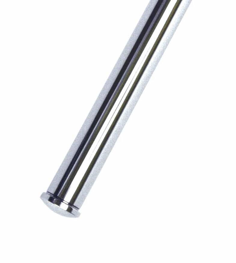
ANGLE PINS
SLIDE COMPONENTS, CAM ACTIONS G-23 NOMINAL DIAMETER CATALOG NUMBER D +.0000 -.0005 L +1/8 -0 B +.0005 -.0000 H +.000 -.010 R HEAD RADIUS P PRESS FIT LENGTH ANGLE T DEPTH 3/8 AP375L6 .374 6 .376 .500 .375 .75 10˚ .258 15˚ .265 AP375L10 10 1.25 20˚ .276 25˚ .291 1/2 AP500L6 .499 6 .501 .625 .500 .75 10˚ .260 15˚ .270 AP500L10 10 1.25 20˚ .284 25˚ .304 5/8 AP625L6 .624 6 .626 .750 .625 .75 10˚ .262 15˚ .274 AP625L10 10 1.25 20˚ .292 25˚ .316 3/4 AP750L10 .749 10 .751 .875 .750 1.25 10˚ .264 15˚ .278 AP750L14 14 20˚ .300 25˚ .329 H D B R P .248 +.000 -.004 L 52 ± 2 HRC R 5 z H ANGLE T +.03 +.02 CAD insertion point M 8620 H Surface: 50-54 HRC
MOLD-READY ANGLE PINS Prefix Pin Diameter Length Specified to 3 decimals 625 L7.244 - - APR L ±.005 Full Radius
ANGLE PIN HOLDERS
APPLICATION GUIDELINES
Angle Pin Holders are provided with 10°, 15°, or 20° angles and allow for machining and installation from parting line.
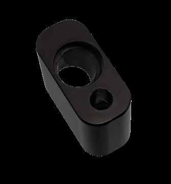
• The In-Line Single Bolt version has a narrow design where space is limited.
• Angle Pins are sold separately on page G-23.
• Includes (1) Socket Head Cap Screw as shown in the chart.
Installation:
1. Machine pockets to nominal sizes as shown in chart.
2. Install Angle Pin from top of Holder.
3. Place entire unit in plate and fasten with the screw.
SLIDE COMPONENTS, CAM ACTIONS G-24 CAD insertion point CATALOG NUMBER ANGLE PIN DIA. H +.000 - .003 L +.000 - .001 W +.000 - .001 R POCKET RADIUS S ± .01 A ANGLE T B D1 +.0005 - .0000 D2 +.005 - .000 SHCS APHS1-37-10 3/8 .875 1.250 .625 .187 .31 10° .258 .813 .3765 .505 1/4-20 x 1 APH1-37-10 1.375 1.375 1/4-20 x 1-1/2 APHS1-37-15 .875 1.375 15° .265 1/4-20 x 1 APH1-37-15 1.375 1.500 1/4-20 x 1-1/2 APHS1-37-20 .875 1.500 20° .276 1/4-20 x 1 APH1-37-20 1.375 1.625 1/4-20 x 1-1/2 APHS1-50-10 1/2 .875 1.375 .750 .250 .31 10° .260 .875 .5015 .630 1/4-20 x 1 APH1-50-10 1.375 1.500 1/4-20 x 1-1/2 APHS1-50-15 .875 1.500 15° .270 1/4-20 x 1 APH1-50-15 1.375 1.625 1/4-20 x 1-1/2 APHS1-50-20 .875 1.625 20° .284 1/4-20 x 1 APH1-50-20 1.375 1.750 1/4-20 x 1-1/2 APHS1-63-10 5/8 .875 1.625 875 .313 .37 10° .262 1.063 .6265 .755 5/16-18 x 1 APH1-63-10 1.375 1.750 5/16-18 x 1-1/2 APHS1-63-15 .875 1.750 15° .274 5/16-18 x 1 APH1-63-15 1.375 1.875 5/16-18 x 1-1/2 APHS1-63-20 .875 1.875 20° .292 5/16-18 x 1 APH1-63-20 1.375 2.000 5/16-18 x 1-1/2 APH1-75-10 3/4 1.500 2.000 1.000 .375 .37 10° .264 1.188 .7515 .885 3/8-16 x 1-5/8 APH1-75-15 2.125 15° .278 APH1-75-20 2.250 20° .300 L B W H T D2 A D1 B D1 R T D2 A R SHCS L SHCS W S .04” Chamfer Centered .04” Chamfer
IN-LINE BOLT M 4140 H 28-32 HRC S Black Oxide H SHCS SHCS SHCS .03 R L H .03 R L L H L H APHS1 Prefix/Style APH1 Prefix/Style •
ANGLE PIN HOLDERS OUTER BOLTS
• The Outer Bolt version installs with two screws and only takes up a minimal amount of space behind the pin.
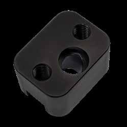
• Includes (2) Socket Head Cap Screws as shown in the chart.
• Angle Pins are sold separately on page G-23. Installation:
1. Machine pockets to nominal sizes as shown in chart.
2. Install Angle Pin from top of Holder.
3. Place entire unit in plate and fasten with the screws.
SLIDE COMPONENTS, CAM ACTIONS G-25
CATALOG NUMBER ANGLE PIN DIA. H +.000 - .003 L +.000 - .001 W +.000 - .001 R POCKET RADIUS S ± .01 A Angle T B D1 +.0005 - .0000 D2 +.005 - .000 SHCS APHS2-37-10 3/8 .875 .750 1.500 .250 1.00 10° .258 312 .3765 .505 1/4-20 x 1 APH2-37-10 1.375 .875 1/4-20 x 1-1/2 APHS2-37-15 .875 .875 15° .265 1/4-20 x 1 APH2-37-15 1.375 1.000 1/4-20 x 1-1/2 APHS2-37-20 .875 1.000 20° .276 1/4-20 x 1 APH2-37-20 1.375 1.125 1/4-20 x 1-1/2 APHS2-50-10 1/2 .875 .875 1.625 313 1.12 10° .260 .375 .5015 .630 1/4-20 x 1 APH2-50-10 1.375 1.000 1/4-20 x 1-1/2 APHS2-50-15 .875 1.000 15° .270 1/4-20 x 1 APH2-50-15 1.375 1.125 1/4-20 x 1-1/2 APHS2-50-20 .875 1.125 20° .284 1/4-20 x 1 APH2-50-20 1.375 1.250 1/4-20 x 1-1/2 APHS2-63-10 5/8 .875 1.125 1.875 .375 1.37 10° .262 .500 .6265 .755 5/16-18 x 1 APH2-63-10 1.375 1.250 5/16-18 x 1-1/2 APHS2-63-15 .875 1.250 15° .274 5/16-18 x 1 APH2-63-15 1.375 1.375 5/16-18 x 1-1/2 APHS2-63-20 .875 1.375 20° .292 5/16-18 x 1 APH2-63-20 1.375 1.500 5/16-18 x 1-1/2 APH2-75-10 3/4 1.500 1.375 2.000 .375 1.50 10° .264 .563 .7515 .885 5/16-18 x 1-5/8 APH2-75-15 1.500 15° .278 APH2-75-20 1.625 20° .300 L B S W H T D2 A D1 B D1 R T D2 A R SHCS L SHCS W S .04” Chamfer Centered .04” Chamfer CAD insertion point M 4140 H 28-32 HRC S Black Oxide
APPLICATION GUIDELINES H SHCS SHCS SHCS .03 R L H .03 R L L H L H APHS2 Prefix/Style APH2 Prefix/Style
ONLINE RESOURCES
When considering design options, numerous animations can be viewed at procomps.com/animations.
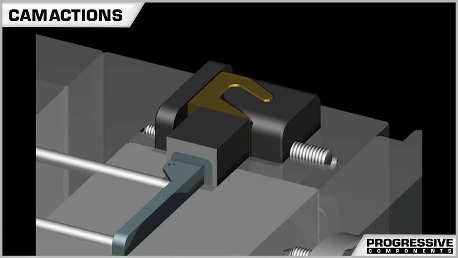
CAD geometry is available online as individual downloads or as part of the CADalog system. The seven formats include: IGES (.igs), ACIS (.sat), STEP (.step), Parasolid (.x_t), SolidWorks (.sldasm), NX (.prt) (Re-Use and MoldWizard) and Visi (.wkf).
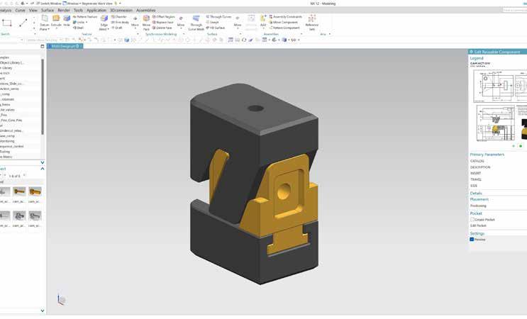

SLIDE COMPONENTS, CAM ACTIONS G-26
Industry-leading web store expedites the purchasing process. Go to shop.procomps.com for information and additional resources.
LIFTERS UNDERCUT RELEASE SECTION
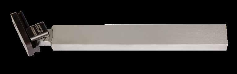
H
Prefix: CB, UC, TG
Page: H-1
Page: H-1
Lifter Guides
Prefix: LG, SGV
Page: H-10
Prefix: FCA, FCR, FCDA
Page: H-18
Versa-Lifter System
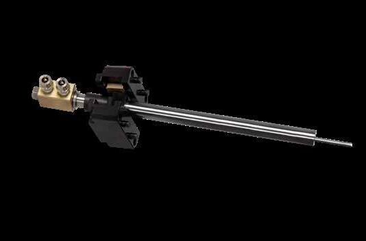
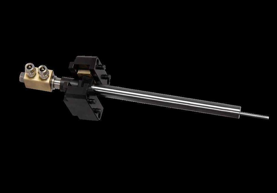
Prefix: UGV, SGV, CBV
Page: H-7
Lifter Head Key
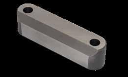
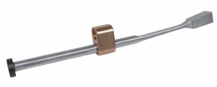
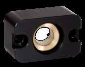

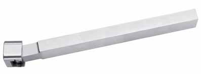
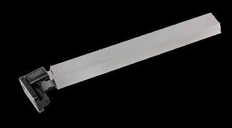
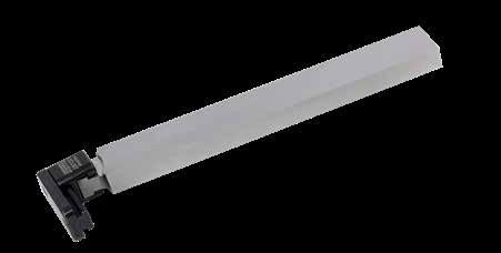
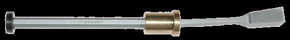
Prefix: LHK
Page: H-11
Core Blade
H-13, 38-42 HRC
UNILIFTER: UL-SERIES
U-Coupling H-13, 70 HRC
T-Gib H-13, 70 HRC
The T-slot’s large surface contact is designed to withstand extreme force and run smoothly without binding.
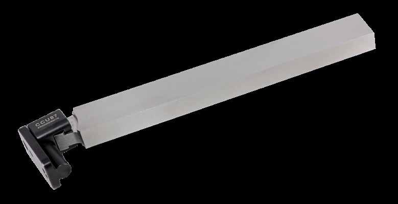
Click-in-place assembly feature sets the components to the required operating position, allowing for simplified insertion into the mold plate pockets.
Self-adjusting cylindrical design to compensate for severe ejector plate misalignment or warpage.
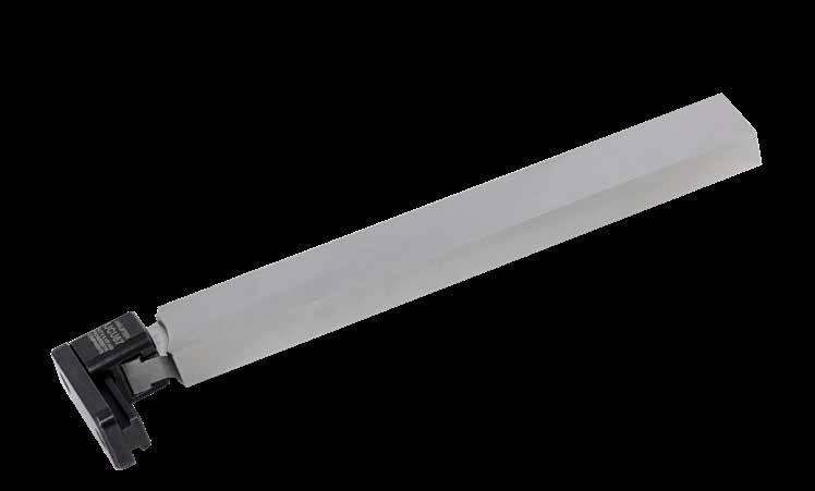
LIFTERS, UNDERCUT RELEASE H-1 UNILIFTER ® UNDERCUT RELEASE LIFTER
Mold Closed
Mold Closed
US Patent Nos 10,220,556 & 11,364,662 Other patents
Mold Open Mold Open
pending.
CORE BLADES INCH STANDARD
Note: S-7 Core Blades come with the assembly detent installed.
Note: S-7 Core Blades come with the assembly detent installed.
For Core Blades in different materials or sizes, refer to the templates at procomps.com.
LIFTERS, UNDERCUT RELEASE H-2
H-13 38-42 HRC S-7 54-56 HRC T +.000 -.001 W +.000 -.001 SIZE L=8” +.06 -.00 L=18” +.06 -.00 L=8” +.06 -.00 L=18” +.06 -.00a COUPLINGS .385 .260 Mini CBS37X25L8 CBS37X25L18 CBS7X37X25L8 CBS7X37X25L18 UL-Series: UCM50 C-Series: CCM50 .510 .260 CBS50X25L8 CBS50X25L18 CBS7X50X25L8 CBS7X50X25L18 .760 .385 CBS75X37L8 CBS75X37L18 CBS7X75X37L8 CBS7X75X37L18 H-13 38-42 HRC S-7 54-56 HRC T +.000 -.001 W +.000 -.001 SIZE L=8” +.06 -.00 L=14” +.06 -.00 L=20” +.06 -.00 L=8” +.06 -.00 L=14” +.06 -.00 L=20” +.06 -.00 COUPLINGS .510 .510 UL CBS50X50L8 CBS50X50L14 CBS50X50L20 CBS7X50X50L8 CBS7X50X50L14 CBS7X50X50L20 UL-Series: UCU87 C-Series: CCU87 .510 .760 CBS50X75L8 CBS50X75L14 CBS50X75L20 CBS7X50X75L8 CBS7X50X75L14 CBS7X50X75L20 .510 1.010 CBS50X100L8 CBS50X100L14 CBS50X100L20 CBS7X50X100L8 CBS7X50X100L14 CBS7X50X100L20 .510 1.510 - CBS50X150L14 CBS50X150L20 - -.760 .510 - CBS75X50L14 CBS75X50L20 - -.760 1.510 CBS75X150L8 CBS75X150L14 CBS75X150L20 - CBS7X75X150L14 CBS7X75X150L20 1.010 .510 CBS100X50L8 CBS100X50L14 CBS100X50L20 - CBS7X100X50L14 CBS7X100X50L20 1.510 .510 CBS150X50L8 CBS150X50L14 CBS150X50L20 - -1.510 .760 CBS150X75L8 CBS150X75L14 CBS150X75L20 - CBS7X150X75L14 CBS7X150X75L20 H-13 38-42 HRC T +.000 -.001 W +.000 -.001 SIZE L=10” +.06 -.00 L=18” +.06 -.00 COUPLINGS 1.010 1.010 XL CBS100X100L10 CBS100X100L18 UL-Series: UCX175 1.010 1.510 CBS100X150L10 CBS100X150L18 1.510 1.010 CBS150X100L10 CBS150X100L18 H-13 38-42 HRC D +.000 -.001 SIZE L=8” +.06 -.00 L=10” +.06 -.00 L=14” +.06 -.00 L=18” +.06 -.00 L=24” +.06 -.00 COUPLINGS .437 Mini CBS43DL8 - - CBS43DL18UL-Series:UCM50 C-Series:CCM50 .500 CBS50DL8 - - CBS50DL18.750 UL CBS75DL8 - CBS75DL14 CBS75DL18 CBS75DL24 UL-Series: UCU87 C-Series: CCU87 1.250 XL - CBS125DL10 - CBS125DL18 - UL-Series:UCX175
Flat Core Blades Flat Core Blades Flat Core Blades Round Core Blades L T W D L
insertion point
CAD
Flat
CORE BLADES METRIC STANDARD
Note: S-7 Core Blades come with the assembly detent installed.
LIFTERS, UNDERCUT RELEASE H-3
H-13 48-50 HRC DC53 58-60 HRC H-13 38-42 HRC S-7 54-56 HRC T -.005 -.015 W -.005 -.015 SIZE L=200MM +2 +0 COUPLINGS 6.00 6.00 Metric Mini CBMMH6X6L200 CBMMP6X6L200 - -UL-Series: UCMM16 6.00 10.00 CBMMH6X10L200 CBMMP6X10L200 - -8.00 6.00 CBMMH8X6L200 CBMMP8X6L200 - -8.00 8.00 CBMMH8X8L200 CBMMP8X8L200 - -10.00 8.00 CBMMH10X8L200 CBMMP10X8L200 - -T +.000 -.025 W +.000 -.025 SIZE L=250MM +2 +0 L=400MM +2 +0 L=250MM +2 +0 COUPLINGS 10.25 10.25 Metric - - CBMM10X10L250 - CBMMS7X10X10L250 UL-Series: UCMM22 C-Series: CCMM22 10.25 20.25 - - CBMM10X20L250 -15.25 15.25 - - CBMM15X15L250 - CBMMS7X15X15L250 15.25 30.25 - - - CBMM15X30L40020.25 10.25 - - CBMM20X10L250 -20.25 20.25 - - - CBMM20X20L40030.25 15.25 - - - CBMM30X15L400H-13 48-50 HRC DC53 58-60 HRC H-13 38-42 HRC D -.005 -.014 SIZE L=200MM +2 +0 COUPLINGS 8.00 Metric Mini CBMMH8DL200 CBMMP8DL200 - UL-Series: UCMM16 D +.000 -.025 SIZE L=250MM +2 +0 COUPLINGS 10.00 Metric - - CBMM10DL250 UL-Series: UCMM22 C-Series: CCMM22 15.00 - - CBMM15DL250
Core Blades Round Core Blades L T W D L
CAD insertion point
UNILIFTER: UL-SERIES COMPONENTS U-COUPLINGS
*TD Includes fitting stock for final adjustments.
LIFTERS, UNDERCUT RELEASE H-4
T-GIBS SIZE CATALOG NUMBER CW CL CH Mini UCM50 .50 .44 .62 UL UCU87 .87 .75 .87 XL UCX175 1.75 1.50 1.65 SIZE CATALOG NUMBER TRAVEL ALLOWED TW +.000 -.001 TH +.010 -.000 TD* +.010 -.000 TR TS ±.01 TL +.000 -.010 A ANGLE SHCS (INCLUDED) Mini TGM31 .312 .500 .500 .344 .093 - .750#10-32 x 1 TGM100 1.000 .50 1.50UL TGU25 .250 .875 .468 .219 .187 - 1.001/4-20 x 3/4 TGU50 .500 .37 1.25TGU100 1.000 .62 1.75TGU100-5 1.000 .610 5° TGU100-10 1.000 .750 10° TGU150 1.500 .468 .75 2.25XL TGX50 .500 1.750 .615 .250 .312 .62 2.003/8-16 x 1-1/4 TGX100 1.000 .87 2.50TGX250 2.500 1.37 4.00SIZE CATALOG NUMBER TRAVEL ALLOWED TW +.000 -.025 TH +.25 -.00 TD* +.25 -.00 TR TS ±.25 TL +.00 -.25 SHCS (INCLUDED) Mini TGMM16 18 16 13 6 2.5 10 33 M4-.7x20 UL TGMM10 15 22 13 6 5 10 33 M5-0.8 x 20 TGMM30 34 15 52 Inch Standard Inch Standard Metric Standard CH CL CW
TW TH TD* TL SHCS (2) TS SHCS (1) TR TL A° TH SIZE CATALOG NUMBER CW CL CH Metric Mini UCMM16 16 14 21 Metric UCMM22 22 18 25 Metric Standard TGM31 & TGU25 TGU100-5 & TGU100-10 M H-13 H Core: 40-44 HRC Surface: 70 HRC M H-13 H Core: 40-44 HRC Surface: 70 HRC S S Black Nitride Black Nitride M H-13 H Core: 40-44 HRC Surface: 70 HRC M H-13 H Core: 40-44 HRC Surface: 70 HRC S S Black Nitride Black Nitride
UNILIFTER: C-SERIES COMPONENTS C-COUPLINGS
APPLICATION GUIDELINES
• C-Series Gibs come with the assembly detent installed.
• Screw thread is not through top of the C-Gib on the Mini sizes.
C-GIBS
LIFTERS, UNDERCUT RELEASE H-5
Inch Standard Metric Standard SIZE CATALOG NUMBER CW CL CH Mini CCM50 .50 .44 .70 UL CCU87 .87 .75 .87 SIZE CATALOG NUMBER CW CL CH Metric CCMM22 22 18 24 SIZE CATALOG NUMBER TRAVEL ALLOWED TW +.000 -.001 TH +.010 -.000 TD* +.010 -.000 TR TS ±.01 TL +.000 -.010 SHCS (INCLUDED) Mini CGM31 .312 .500 .550 .250 .093 - .750 #10-32 x 1 CGM100 1.000 .50 1.50 UL CGU50 .500 .875 .540 .187 .187 .37 1.25 1/4-20 x 3/4 CGU100 1.000 .62 1.75 SIZE CATALOG NUMBER TRAVEL ALLOWED TW +.000 -.025 TH +.25 -.00 TD* +.25 -.00 TR TS ±.25 TL +.00 -.25 SHCS (INCLUDED) UL CGMM10 15 22 15 6 5 10 33 M5-0.8 x 20 Inch Standard Metric Standard TS SHCS (1) TR SHCS (2) TW CW CL TH CH
Includes
for final adjustments. CGM31 .020” / .5mm Initial Position CAD insertion point US Patent Nos 10,220,556 & 11,364,662 Other patents pending. TS SHCS (1) TR SHCS (2) TD* TL TW CW CL TH CH M H-13 H Core: 40-44 HRC Surface: 70 HRC M H-13 H Core: 40-44 HRC Surface: 70 HRC S S Black Nitride Black Nitride M H-13 H Core: 40-44 HRC Surface: 70 HRC M H-13 H Core: 40-44 HRC Surface: 70 HRC S S Black Nitride Black Nitride
*TD
fitting stock
C-SERIES LIFTER SYSTEMS INSTALLATION INSTRUCTIONS / APPLICATION GUIDELINES
Install Core Blade, C-Gib and C-Coupling into the mold base. Align arrows to orient with ejection travel.
C-Series Lifter Features
Assemble the ejector plates and fasten the C-Gib into the pocket.
1 2 3
Assembly detents allow the toolmaker to set the Core Blade, C-Coupling and C-Gib to the correct angle and position, allowing easy assembly into the mold pocket without parts sliding out of position.
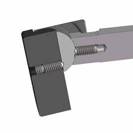
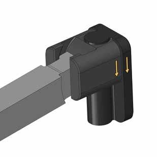
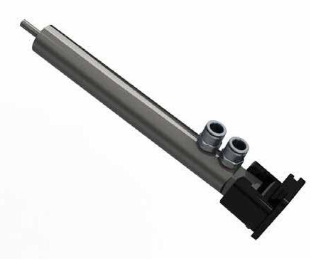
With the mold assembled, check to verify final position of the lifter. Adjust by grinding the back of the C-Gib as required.
Maintenance Option: Should ejector plates warp over time, the C-Series Gib and Coupling can directly replace the UniLifter Series without altering the Core Blades.
H
SIZE H
Mini .719”
UL .812”
Metric 22mm
UL-SERIES & C-SERIES APPLICATION GUIDELINES
• Typical Core Blade angle is 5-10˚. For greater angles, Lifter Guides are recommended.
• Lifter Guides are also recommended if less than half of the Core Blade is bearing in the insert. Refer to page H-10 for Guides.
• Typical clearance is .001”-.0015” (.02-.04 mm), or a 3° taper on the Core Blade T & W to eliminate contact and friction.
• Core Blades are interchangeable between the UL-Series and C-Series.
• If treating the S-7 Core Blades, the assembly ball plunger should be removed prior to processing.
• For any questions including the availability of water-cooled Core Blades (as shown at left) or unusual applications, contact Progressive for an application review at tech@procomps.com.
LIFTERS, UNDERCUT RELEASE H-6
US
Nos 10,220,556 & 11,364,662 Other patents pending.
Patent
VERSA-LIFTER ™ UNDERCUT RELEASE SYSTEM
Lifter Support Guides are available for when support plate alignment is required.
Open Clearance support plate in core Clearance assembly Ejector Plate Travel Versa-Lifter Travel = Tan (Angle) x Ej Plt Travel
Closed Versa-Lifter Travel = Tan (Angle) x Ej Plt Travel
• In addition, if space is limited at parting line, the Core Blade can be stepped.
Mold
Core Blades are manufactured from hardened material, ready for molding detail. Mold Ejector Plate Travel
APPLICATION GUIDELINES
• Typical angles are 5-10˚, but users have reported success at larger angles for unique applications with greater bearing, such as cavity side core pulls. Contact tech@procomps.com for an application review.
• Guided Ejection is required, and the Lifter Support Guides are recommended in all applications. (See page H-10)
• Recommended total clearance is .001”-.0015” (.025-.038mm) where permissible.
• Core material should be at least 10 HRC different than the Core Blade material.
• Locking angles can be designed to counter molding pressure.
• Made-to-order Core Blades can be provided by sending a request to tech@procomps.com.
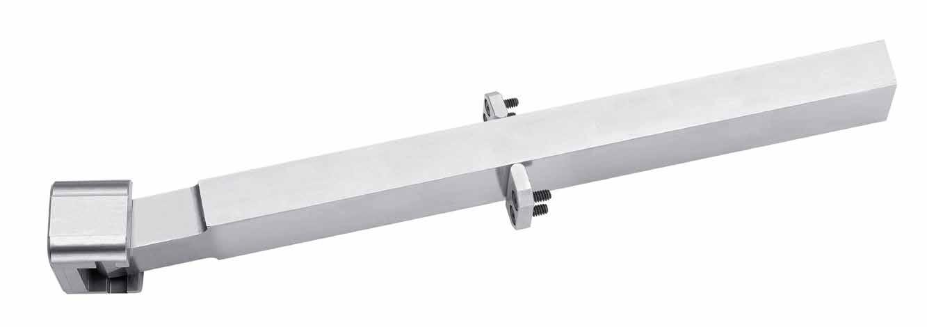
LIFTERS, UNDERCUT RELEASE H-7
Gib Coupling retains the Core Blade and supports vertical movement. Clearance in support plate and in core Clearance for assembly
Design Options
• For positive return, a locking angle can be designed into the Core Blade as shown at right.
• Assembly length cap screw (#10-32 x 4”) and Dowel Pin is included with each Gib Coupling, sold separately below.
• Install the assembly screw in the Gib Coupling as shown.
• Connect the lifter pin and pull unit into pocket in ejector plate, removing the screw afterwards.
• Lifter Guides are shown on page H-10.
GIB COUPLINGS
* .005” stock is included on the bottom for fitting. Includes #10-32 x 4” long screw.
LIFTERS, UNDERCUT RELEASE H-8 VERSA-LIFTER ™ CORE BLADES
CATALOG NUMBER T +.0000 -.0003 W +.0000 -.0003 MW +.000 -.001 CBV50X18L8 .5000 .1875 .188 CBV50X43L8 .4375 .188 CBV50X62L8 .6250 .375 CBV50X87L8 .8750 .625 CBV50X112L8 1.1250 .875
Insert dowel and pull coupling into pocket .110 +.01 to retain Gib Coupling CATALOG NUMBER A CENTRAL B +.001 -.000 COMPATIBLE CORE BLADE WIDTHS (W) UGV68 .6860 .190 .1875 & .4375 UGV87 .8735 .377 .6250 UGV112 1.1235 .627 .8750 UGV137 1.3735 .877 1.1250
Gib Coupling Dowel
CH W 8.00 +.06 -.00 +.0000 -.0003 T W 8.00 .188 Full .093 Radius A B .755* .19 R (4) .8750 .124 (2) .1872 .500 +.0005 -.0000 ±. 001 55 ±1 HRC M S-7 H 54-56 HRC S Salt Bath Nitride M Bohler K340 H 58-60 HRC +.06 -.00 T W 8.00 .281 R 3/16ø Pin 3/16ø Dowel MW S W .344 .188 .500* Full .093 Radius A B .755* .19 R (4) .8750 .124 (2) .1872 .500 +.0005 -.0000 ±. 001 55 ±1 HRC CAD insertion point APPLICATION GUIDELINES
LIFTER ACCESSORIES SPHERICAL BUSHINGS
APPLICATION GUIDELINES
• Machine pocket with clearance on length and width.
• Tighten bolts after inserting lifter rod.
Housing: Bushing:
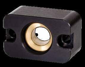
M 1045 H 18-22 HRC
M C86300 Bronze
BLANK SPHERICAL BUSHINGS
To Order Blanks: Add “-B” to the end of the part number. Ex: LSB100-B
• Sizes 075-B and smaller have a .23” Pilot Hole.
• Sizes 100-B and larger have a .47” Pilot Hole.
Use the blank bushing to cut alternative core blade sizes. See chart for recommended sizing.
CBS37X25, CBS50X25, CBS50X50, CBS43D, CBV50X18, CBV50X43, CBMM10D, CBMM10X10 LSB063
CBMM15D, CBMM15X15
3/4 X 3/4 CBS75X37, CBMM20X10, CBMM20X20 LSB100 1 X 1
CBS100X100, CBS75D, CBV50X87
LSB125 1-1/4 X 1-1/4 CBS125D, CBV50X112, CBMM30X15
CBS150X150, CBS150X75, CBS150X100
LIFTERS, UNDERCUT RELEASE H-9
CATALOG NUMBER D +. 001 -.000 L +. 000 -.002 W +. 000 -.002 T +.000 -.002 S ±.005 R POCKET RADIUS SHCS LSB050 .5005 2.000 1.250 .875 1.500 .250 1/4-20 x 1 LSB063 .6255 2.250 1.500 1.125 1.750 .250 1/4-20 x 1-1/4 LSB075 .7505 2.625 1.750 1.375 2.125 .375 5/16-18 x 1-1/2 LSB100 1.0005 2.875 2.125 1.500 2.375 .375 5/16-18 x 1-3/4 LSB125 1.2505 4.000 2.750 2.000 3.250 .500 3/8-16 x 2-1/4 LSB150 1.5005 4.250 3.000 2.375 3.500 .500 3/8-16 x 2-3/4 CAD insertion point
SPHERICAL BUSHING SIZE LIFTER T X W (MAX) UNILIFTER SIZE CHART LSB050
Screws included.
1/2 X 1/2
CBV50X62,
5/8 X 5/8
LSB075
CBS100X50,
LSB150 1-1/2 X 1-1/2
Pilot Hole T W Pilot Hole T W
L S W R SHCS T Max 20° D
LIFTER ACCESSORIES LIFTER GUIDES
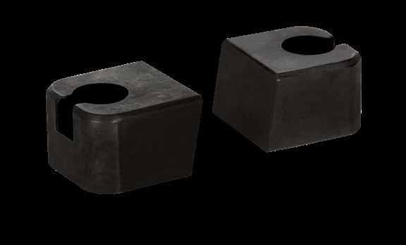
Lifter Guides are sold in sets with Socket Head Cap Screws included. LG150 items have 4 screws as shown in the locations below.
VERSA-LIFTER GUIDES
APPLICATION GUIDELINES
• *Includes .005” fit stock on flat side.
• Sold in sets.
• Four (4) #6-32 LHCS are included.
LIFTERS, UNDERCUT RELEASE H-10
W +.000 -.001 CATALOG NUMBER T ±.015 L1 S1 ±.01 S2 ±.01 S3 ±.01 R POCKET RADIUS Z CHAMFER SHCS A=5° A=10° A=15° .375 LG37-5 LG37-10 LG37-15 .375 .500 .18 .18 .125 .02 #6-32 x 1/2 .500 LG50-5 LG50-10 LG50-15 .500 .750 .25 .25 .03 #10-32 x 3/4 .750 LG75-5 LG75-10 LG75-15 .37 .187 1.000 LG100-5 LG100-10 LG100-15 .875 .50 .31 .250 1/4-20 x 3/4 1.500 LG150-5 LG150-10 LG150-15 .37 .75 .250
S2 S1 S3 SIZE OF GUIDE CAN BE USED WITH UNILIFTER CORE BLADE SIZE MAX BLADE WIDTH (FOR OTHER SYSTEMS) LG37 37X25 50X25 75X37 .385 LG50 50X50 75X50 100X50 150X50 .510 LG75 150X75 .760 LG100 100x100 150x100 1.010 LG150 50X150 75X150 100X150 1.510 S2 S1 W SHCS R L1 T Z Aº CAD insertion point M O-1 H 58-60 HRC S Black Oxide LG150 CATALOG NUMBER W S SGV43 .436 On Center SGV62 .624 On Center SGV87 .874 .187 SGV112 1.124 .312 CH S W .344 .188 .500* Full .093 Radius A B .755* .19 R (4) .8750 .124 (2) .1872 .500 +.0005 -.0000 ±. 001 55 ±1 HRC M S-7 H 54-56 HRC
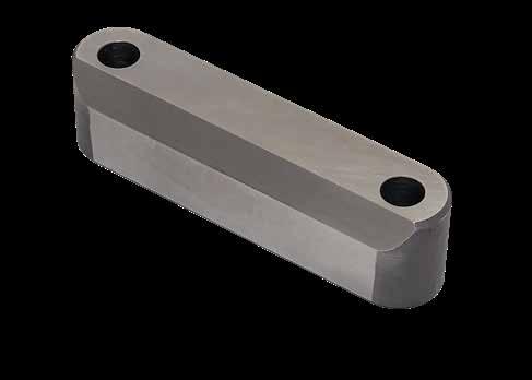
LIFTERS, UNDERCUT RELEASE H-11
LIFTER HEAD KEY SHCS L F T W S CATALOG NUMBER NOMINAL ROD DIAMETER W +.00 -.01 L ±.005 T +.000 -.005 F S ±.01 SHCS LHK050 1/2 1.370 .500 .375 .19 .87 #6-32 x 1/2 LHK063 5/8 1.495 .500 .375 .19 1.00 #6-32 x 1/2 LHK075 3/4 1.620 .500 .500 .19 1.12 #8-32 x 1/2 LHK100 1 1.870 .500 .500 .19 1.37 #8-32 x 1/2 LHK125 1-1/4 2.620 .750 .625 .25 2.00 1/4-20 x 7/8 LHK150 1/1/2 2.870 .750 .625 .25 2.25 1/4-20 x 7/8 Screws included. CAD insertion point M 4140 H 28-32 HRC
LIFTER ACCESSORIES
MODULIFTER ® UNDERCUT RELEASE SYSTEM
A standardized modular lifter assembly simplifies undercut release:
• Specialized design for accelerated and decelerated applications.
• Additional lifter cooling options and components available.
Straight Travel
Accelerated/ Decelerated Options
Cooled: Single Rod In/Out
Cooled: Dual Rod In/Out
LIFTERS, UNDERCUT RELEASE H-12
STANDARD ASSEMBLY
SL
+.001 -.000 .125 H/ 2 H SL
L W SHCS
Rod (sold separately) CATALOG NUMBER L +.000 -.015
Base Assembly includes:
• Rod Coupling Assembly
• Gibs (2)
• Mounting Screws (4)
G L
Gibs/Coupling: M 1045 H 28-32 HRC S Nitride Slides: M C86300 Bronze M 1045 H Core: 28-32 HRC, Surface: 56-58 HRC
+.001 -.000 .125 H/ 2 H Aº G F D L Thread for screw
F +.000 -.001
G +.03 -.00 SCREW SIZE .500 MLR050L14 14 .450 .50 1/4-20 x 5/8 .625 MLR063L14 14 .590 .56 5/16-18 x 3/4 .750 MLR075L16 16 .690 .68 3/8-16 x 7/8 1.000 MLR100L16 16 .875 .75 1/2-13 x 1 1.500 MLR150L18 18 1.400 1.00 5/8-11 x 1-1/2
W +.000 -.002
H +.000 -.001
D F BASE ASSEMBLY LIFTER ROD
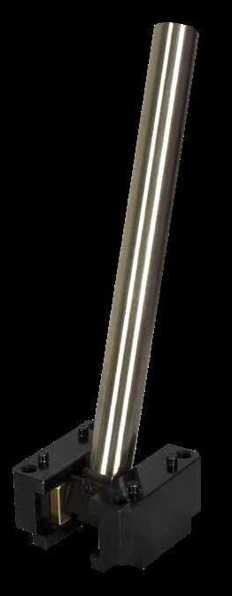
D +.0003 -.0000
G F THD
F +.0015 -.0000 SHCS SL TRAVEL (L-SL) A=0° A=5° A=10° 1/2 MLBA050 MLBA050-5 MLBA050-10 2.250 2.250 1.375 .5003 .4505 1/4-20 x 1-1/2 1.38 .87 5/8 MLBA063 MLBA063-5 MLBA063-10 2.625 2.500 1.375 .6253 .5905 1/4-20 x 1-1/2 1.57 1.06 3/4 MLBA075 MLBA075-5 MLBA075-10 2.750 3.000 1.750 .7503 .6905 5/16-18 x 2 1.57 1.18 1 MLBA100 MLBA100-5 MLBA100-10 3.125 3.250 1.750 1.0003 .8755 5/16-18 x 2 1.77 1.35 1-1/2 MLBA150 MLBA150-5 MLBA150-10 4.750 4.250 2.500 1.5003 1.4005 3/8-16 x 2-3/4 3.15 1.60 Includes (4) Socket Head Cap Screws and (4) Dowels. D +.0000 -.0003 CATALOG NUMBER L +.13 -.00
APPLICATION GUIDELINES
• Includes (1) Socket Head Cap Screw for installation.
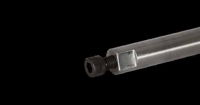
• For additional Lifter Rod lengths, contact tech@procomps.com.
CAD insertion point CAD insertion point
LIFTERS, UNDERCUT RELEASE H-13 Aº L W SHCS H SL +.001 -.000 .125 D F
MODULIFTER ®
• Dowels installed NOMINAL ROD DIAMETER
APPLICATION GUIDELINES
• The ModuLifter Cooling Base Assemblies have three (3) options for varying water connections.
• Additional accessories are shown below.
COOLED BASE ASSEMBLY
COOLED LIFTER ROD
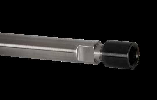
APPLICATION GUIDELINES
• Includes (1) Installation Nut. Replacement nuts are available.
• For additional Cooled Lifter Rod lengths, contact tech@procomps.com.
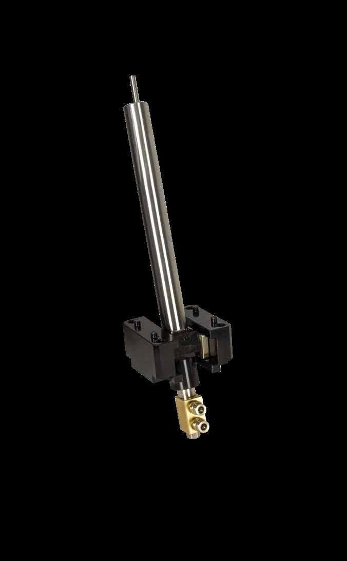
LIFTERS, UNDERCUT RELEASE H-14 + .0000 -.0003 CATALOG NUMBER L +.13 -.00 T1 INTERNAL THREAD T2 EXTERNAL THREAD G +.03 -.00 F +.000 -.001 .625 MLCR063L14 .250 14.75 14 5/16-24 1/2-20 .56 .590 .750 MLCR075L16 .250 16.88 16 5/16-24 1/2-20 .68 .690 1.000 MLCR100L16 .375 17.00 16 1/2-20 3/4-20 .75 .875 1.500 MLCR150L18 .375 19.38 18 1/2-20 7/8-20 1.00 1.400 NOMINAL ROD DIAMETER CATALOG NUMBER L +.000 -.015 W +.000 -.002 H +.000 -.001 D +.0003 -.0000 F +.0015 -.0000 SHCS SL TRAVEL (L-SL) A=0° A=5° A=10° 5/8 MLCBA063 MLCBA063-5 MLCBA063-10 2.625 2.500 1.375 .6253 .5905 1/4-20 x 1-1/2 1.57 1.06 3/4 MLCBA075 MLCBA075-5 MLCBA075-10 2.750 3.000 1.750 .7503 .6905 5/16-18 x 2 1.57 1.18 1 MLCBA100 MLCBA100-5 MLCBA100-10 3.125 3.250 1.750 1.0003 .8755 5/16-18 x 2 1.77 1.35 1-1/2 MLCBA150 MLCBA150-5 MLCBA150-10 4.750 4.250 2.500 1.5003 1.4005 3/8-16 x 2-3/4 3.15 1.60 Includes (4) Socket Head Cap Screws and (4) Dowels. G OD NUT T2 ROD G OD L NUT T2 F ROD ID T1 OAL
• Gibs (2)
•
Cascade
Base Assembly includes: • Rod Coupling Assembly
• Mounting Screws (4)
Dowels installed Rod (sold separately)
(Sold separately.)
Aº L W SHCS H SL +.001 -.000 .125 D F CAD insertion point CAD insertion point Gibs/Coupling: M 1045 H 28-32 HRC S Nitride Slides: M C86300 Bronze M 1045 H Core: 28-32 HRC, Surface: 56-58 HRC
Face Seal O-Ring Page E-17 Lifter Head Key Page H-11
PARALLEL (IN & OUT) SERIES (IN & OUT) SINGLE (IN ONLY)
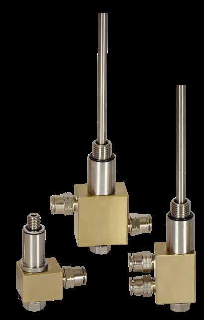
LIFTERS, UNDERCUT RELEASE H-15 MODULIFTER ® COOLING CASCADES
OD ID CATALOG NUMBER OD ID CATALOG NUMBER ID CATALOG NUMBER THD MAX TORQUE NOMINAL ROD DIAMETER .157 .12 MLCP16L25 .157 .12 MLCS16L25 .12 MLC12 5/16-24 75 in-lbs 5/8, 3/4 .236 .20 MLCP23L25 .236 .20 MLCS23L25 .20 MLC20 1/2-20 20 ft-lbs 1, 1-1/4, 1-1/2 • Straight Fittings included with Cooling Cascades. • Replacement O-Rings available. Specify MLC312-OR (for .12 ID) or MLC500-OR (for .20 ID). OD ID OD ID 27.38 25 27.38 25 1.0 1.25 1.0 A HEX1 HEX2 HEX1 HEX2 A D L B B OAL OAL For Ø1/4” Hose For Ø1/4” Hose For Ø1/4” Hose Out In Out In THD THD THD FITTING TYPE CATALOG NUMBER HOSE OD THD (NPT) HEX1 HEX2 A OAL Straight MLFS25 1/4 1/8 1/2 5/32 .87 Elbow MLFE25 1/4 1/8 1/2 .83 Banjo MLFB25 1/4 1/8 9/16 1/8 .81 1.22 CATALOG NUMBER HOSE OD HOSE ID TURNS OAL L B D MLH25-5 1/4 5/32 5 10.5 in 2.5 4 1.5 MLH25-10 1/4 5/32 10 13.0 in 5.0 4 1.5 MLH25-25 1/4 5/32 Straight 25.0 ft Maximum Operating Temperature 160° F (70°C) Maximum Operating Temperature 160°F (70°C). OD ID 27.38 25 1.0 1.25 A HEX1 HEX2 HEX1 HEX2 A D L B B OAL OAL For Ø1/4” Hose OAL For Ø1/4” Hose For Ø1/4” Hose Out In THD THD OD ID OD ID 27.38 25 27.38 25 1.0 1.25 HEX1 HEX2 HEX1 HEX1 HEX2 D L B B OAL OAL For Ø1/4” Hose OAL For Ø1/4” Hose For Ø1/4” Hose Out In Out In THD THD TH OD ID OD ID 27.38 25 27.38 25 1.0 1.25 A HEX1 HEX1 HEX2 D L B B OAL For Ø1/4” Hose OAL For Ø1/4” Hose Out In Out In THD THD OD ID OD 27.38 25 1.0 1.25 ID A HEX1 HEX2 HEX1 HEX2 A D L B B OAL OAL 1.75 For Ø1/4” Hose OA For Ø1/4” Hose Out In Out In THD THD PUSH-TO-CONNECT HOSE FITTINGS PUSH-TO-CONNECT SPIRAL AND STRAIGHT HOSES OD ID OD ID 27.38 25 27.38 25 1.0 1.25 1.0 ID A HEX1 HEX2 HEX1 HEX2 A D L B B OAL OAL 1.75 For Ø1/4” Hose OAL For Ø1/4” Hose For Ø1/4” Hose Out In Out In THD THD THD OD ID OD ID 27.38 25 27.38 25 1.0 1.25 1.0 ID A HEX1 HEX2 HEX1 HEX2 A D L B B OAL OAL 1.75 For Ø1/4” Hose OAL For Ø1/4” Hose For Ø1/4” Hose Out In Out In THD THD THD M C86300 and Stainless Steel. Fittings: Nickel Plated Brass. M Nickel Plated Brass with Sealant M Polyurethane Swivel Type
Bushings: M C95400 Retaining Ring: M Steel S Black Oxide
Includes (1) Retaining Ring. Replacement Retaining Rings are available. To order, specify the prefix of RR before the ID. Ex. RR50 for a 1/2 ID ring.
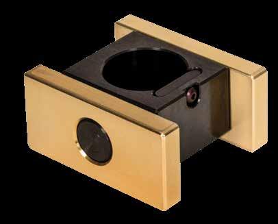
Coupling: M 1045 H 28-32 HRC S Nitride
Slides: M C86300 Bronze
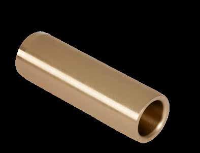
LIFTER ROD SPACER
LIFTERS, UNDERCUT RELEASE H-16 MODULIFTER ® LIFTER ROD BUSHING ROD COUPLING ASSEMBLY PLATE MACHINING OPTION L B D Bore Dia. Groove Width Bushing Groove Dia. F L W A D H D1 +.001 -.000 .125 H A(2) W Bushing Dia. BD BD GW Retaining Ring (Included) Bushing GD D GW Retaining Ring Bushing GD B Dia. Bushing Dia. L H A(2) W Bushing Dia. NOMINAL ROD DIAMETER CATALOG NUMBER W +.002 -.000 H ± .001 A +.010 -.000 NONCOOLED COOLED 1/2 RC050 1.187 .788 .66 5/8 RC063 RCC063 1.310 .788 .78 3/4 RC075 RCC075 1.500 .946 .97 1 RC100 RCC100 1.781 1.024 1.21 1-1/2 RC150 RCC150 2.656 1.498 1.84 CATALOG NUMBER D +.001 -.000 B +.0005 -.0000 L +.00 -.01 GD +.005 -.000 GW +.005 -.000 BD ± .002 MLBSH50L1.37 .5005 .750 1.375 .862 .046 .813 MLBSH63L1.37 .6255 .875 1.375 1.000 .046 .934 MLBSH75L3.37 .7505 1.125 3.375 1.262 .056 1.188 MLBSH100L4.37 1.0005 1.375 4.375 1.528 .056 1.438 MLBSH150L5.87 1.5005 2.000 5.875 2.186 .086 2.063
CATALOG NUMBER OD +.00 -.01 ID +.000 -.005 T +.000 -.001 MLRS050 .500 .30 .063 MLRS063 .625 .53 MLRS075 .750 .53 MLRS100 1.000 .80 MLRS150 1.500 .93 T OD ID Spacer
M D-2 H 58-60 HRC
INSTALLATION GUIDELINES FOR BASE ASSEMBLIES
INSTALLATION METHODS
LIFTERS, UNDERCUT RELEASE H-17 MODULIFTER ®
INSTALLATION DIMENSIONS NOMINAL ROD DIAMETER S1 ± .01 S2 ± .01 P1 DOWEL ±.0005 P2 DOWEL ±.0005 R POCKET MAX D1 +.0005 -.0000 Z1 +.03 -.00 1/2 1.75 1.75 1.750 .750 .19 .2500 .28 5/8 2.00 2.00 2.000 1.000 3/4 2.25 2.25 2.250 1.250 1 2.50 2.50 2.500 1.500 1-1/2 3.50 4.00 3.500 2.500 .25 .3750 .41 G2 S2 G1 P1 Dowel S1 R D2 D1 Z2 Z1 L P2 Dowel G2 G1 P1 Dowel S1 D2 D1 Z2 Z1 L ACCEL./DECEL. KEYING DOWEL G1 ± .005 G2 ± .005 D2 DRILL DIA. Z2 DRILL DEPTH +.03/-.00 .75 1.00 .125 .19 .75 1.25 .75 1.50 1.00 1.75 1.50 2.50 .188 .23
G2 G1 P1 Dowel S1 D2 D1 Z2 Z1 Dowel G2 S2 G1 P1 Dowel S1 R D2 D1 Z2 Z1 P2 Dowel Bottom Mount Top Mount
Flats prevent twisting and ensure proper alignment.
Bronze Guide is used for positional alignment and guidance during ejection. Two options available: Bottom (as shown) and Round for easy bore machining.
Heel Plate is included to retain FlexiCore.
Mold Closed
APPLICATION GUIDELINES
• The FlexiCore diameter (D) must be within the Guide prior to ejection as shown above.
• Only surface treatments applied at low temperatures such as Electroless Nickel-based or chromium deposition treatments are permitted.
• Maximum temperature is 250°F (125°C).
• FlexiCore Assembly includes: FlexiCore, Bronze Guide (Bottom or Round), Heel Plate, and Flat Head Cap Screw.
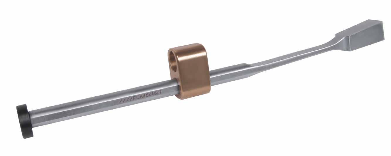
• Please contact tech@procomps.com to review any designs if questions arise or if your application differs from the examples shown
Improved materials used to increase the life of the FlexiCore during production.
Mold Open
LIFTERS, UNDERCUT RELEASE H-18 1/2 T Max .375"
Min. .003
.005
(9.5mm)
(.07mm) to
(.12mm)
APPLICATION GUIDELINES
• The FlexiCore can be cut down and re-tapped to accommodate specific applications.
• Assemblies include FlexiCore, Bottom Guide, Heel Plate, and Flat Head Cap Screw.
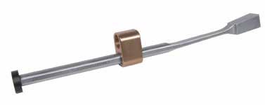
• Assembly components also sold individually on page H-23.
BOTTOM GUIDE ASSEMBLY
“E”= maximum travel at the top of the FlexiCore. Expected travel is reduced by the tangent of 6˚ along the “C” dimension.
M FlexiCore: AISI 4340 with thin, dense Chromium treatment, Guide: CA954 Solid Bronze, Heel Plate: AISI 1018
LIFTERS, UNDERCUT RELEASE H-19
™
FLEXICORE
S .75 [19mm] W D .61 [16mm] T Bottom Guide Heel Plate .625 [16mm] 1.000 [25mm] .500 (Inch Std.) 12mm (Metric Std.) 6˚ E C OAL L G .625 [16mm] FLATS (2) .188 [4mm] J ??? 65 HRC SHCS 35 ±3 HRC 170 B Nitrided .01" (.25mm) Deep E
Inch Standard CATALOG NUMBER T +.002 -.000 W +.002 -.000 L +.010 -.000 OAL REF D +.000 -.001 C ±.015 E G +.01 -.00 J S (INCLUDED) SHCS FCA35X24L6 .354 .244 6.400 6.588 .234 .875 .137 3.49 .957 #8-32 x 3/8 1/4-20 FCA35X32L6 .354 .322 6.400 6.588 .250 .875 .137 3.48 .957 #8-32 x 3/8 1/4-20 FCA45X40L7 .453 .401 7.875 8.062 .312 1.000 .177 4.38 1.025 #10-24 x 1/2 1/4-20 FCA45X48L7 .453 .480 7.875 8.062 .312 1.000 .177 4.38 1.025 #10-24 x 1/2 1/4-20 Metric Standard CATALOG NUMBER T +.05 -.00 W +.05 -.00 L +.25 -.00 OAL REF D +.000 -.025 C ± .35 E G +.25 -.00 J S (INCLUDED) SHCS FCA9X6L160 9 6.2 162.5 166.5 5.94 22 3.5 88.6 24.3 M4-0.7 x 12 M6-1 FCA9X8L160 9 8.2 162.5 166.5 6.35 22 3.5 88.4 24.3 M4-0.7 x 12 M6-1 FCA11X10L200 11.5 10.2 200.0 204.0 7.92 26 4.5 111.2 26.0 M5-0.8 x 14 M6-1 FCA11X12L200 11.5 12.2 200.0 204.0 7.92 26 4.5 111.2 26.0 M5-0.8 x 14 M6-1 FCA12X14L200 12.5 14.2 200.0 204.0 7.92 30 4.5 107.2 28.5 M5-0.8 x 14 M6-1 FCA12X16L200 12.5 16.2 200.0 204.0 7.92 30 4.5 107.2 28.5 M5-0.8 x 14 M6-1 CAD insertion point
APPLICATION GUIDELINES
• The FlexiCore can be cut down and re-tapped to accommodate specific applications.
• Assemblies include FlexiCore, Round Guide, Heel Plate, and Flat Head Cap Screw.
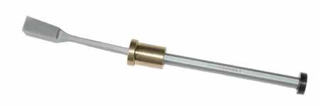
• Assembly components also sold individually on page H-23.
Inch Standard
“E”= maximum travel at the top of the FlexiCore. Expected travel is reduced by the tangent of 6˚ along the “C” dimension.
M FlexiCore: AISI 4340 with thin, dense Chromium treatment, Guide: CA954 Solid Bronze, Heel Plate: AISI 1018
H-20 FLEXICORE ™ ROUND GUIDE ASSEMBLY S .75 [19mm] W T Round Guide Heel Plate J 6˚ E C OAL L G B A FLATS (2) D .61 [16mm] .188 [4mm] .187 [5mm] 1.000 [25mm] Nitrided .01" (.25mm) Deep 35 ±3 HRC 170 B CATALOG NUMBER T +.05 -.00 W +.05 -.00 L +.25 -.00 OAL REF D +.000 -.025 C ±.35 E G +.25 -.00 J S (INCLUDED) A B5 FCR9X6L160 9 6.2 162.5 166.5 5.94 22 3.5 88.6 24.3 M4-0.7 x 12 16 12 FCR9X8L160 9 8.2 162.5 166.5 6.35 22 3.5 88.4 24.3 M4-0.7 x 12 16 12 FCR11X10L200 11.5 10.2 200.0 204.0 7.92 26 4.5 111.2 26.0 M5-0.8 x 14 20 16 FCR11X12L200 11.5 12.2 200.0 204.0 7.92 26 4.5 111.2 26.0 M5-0.8 x 14 20 16 FCR12X14L200 12.5 14.2 200.0 204.0 7.92 30 4.5 107.2 28.5 M5-0.8 x 14 20 16 FCR12X16L200 12.5 16.2 200.0 204.0 7.92 30 4.5 107.2 28.5 M5-0.8 x 14 20 16 Metric Standard CATALOG NUMBER T +.002 -.000 W +.002 -.000 L +.010 -.000 OAL REF D +.000 -.001 C ± .015 E G +.01 -.00 J S (INCLUDED) A B5 FCR35X24L6 .354 .244 6.400 6.588 .234 .875 .137 3.49 .957 #8-32 x 3/8 .625 .500 FCR35X32L6 .354 .322 6.400 6.588 .250 .875 .137 3.48 .957 #8-32 x 3/8 .625 .500 FCR45X40L7 .453 .401 7.875 8.062 .312 1.000 .177 4.38 1.025 #10-24 x 1/2 .750 .625 FCR45X48L7 .453 .480 7.875 8.062 .312 1.000 .177 4.38 1.025 #10-24 x 1/2 .750 .625 CAD insertion point
LIFTERS, UNDERCUT RELEASE
E
APPLICATION GUIDELINES
• The FlexiCore can be cut down and re-tapped to accommodate specific applications.
• Assemblies include two FlexiCores, one Bottom Guide, one Heel Plate, and two Low Head Cap Screws
• Assembly components also sold individually on page H-23.
Inch Standard
“E”= maximum travel at the top of the FlexiCore. Expected travel is reduced by the tangent of 6˚ along the “C” dimension.
M FlexiCore: AISI 4340 with thin, dense Chromium treatment, Guide: CA954 Solid Bronze, Heel Plate: AISI 1018
Metric Standard
LIFTERS, UNDERCUT RELEASE H-21 FLEXICORE ™ DOUBLE ACTUATION S 19mm W T Bottom Guide Heel Plate J 6˚ FLATS (2) C OAL L G E 35 ±3 HRC Nitrided .01" (.25mm) Deep 170 B CATALOG NUMBER T +.002 -.000 W +.002 -.000 L +.010 -.000 OAL REF D +.000 -.001 C ±.015 E ±.015 G +.01 -.00 J +.01 -.00 S (INCLUDED-2) FCDA35X24L6 .354 .244 6.400 6.588 .234 .875 .137 3.49 .957 #8-32 x 3/8 FCDA45X48L7 .453 .480 7.875 8.062 .312 1.000 .177 4.38 1.025 #10-24 x 1/2 CATALOG NUMBER T +.05 -.00 W +.05 -.00 L +.25 -.00 OAL REF D +.000 -.025 C ±.035 E 015 G +.25 -.00 J +.01 -.00 S (INCLUDED-2) FCDA9X6L160 9 6.2 162.5 166.5 5.94 22 3.5 88.6 24.3 M4-0.7 x 12 FCDA11X12L200 11.5 12.2 200.0 204.0 7.92 26 4.5 111.2 26.0 M5-0.8 x 14 FCDA12X14L200 12.5 14.2 200.0 204.0 7.92 30 4.5 107.2 28.5 M5-0.8 x 14 FCDA12X16L200 12.5 16.2 200.0 204.0 7.92 30 4.5 107.2 28.5 M5-0.8 x 14
CAD insertion
point
E
The Wear Block installs from parting line, utilizing the same screw hole location as the Bottom Guide.
LIFTERS, UNDERCUT RELEASE H-22 FLEXICORE ™ ACCESSORIES WEAR BLOCKS A B x .75 [19mm] Deep D L .37 [9mm] wide Wrench Flats 1/2 L 30 ±2 HRC D +.000 -.005 B A L +.01 -.00 2” 4” .232 #8-32 .187 FCX8L2 FCX8L4 .310 #10-24 .250 FCX10L2 FCX10L4 Inch Standard Includes threaded stud for attachment to FlexiCore. D +.00 -.12 B A L +.25 -.00 50MM 100MM 6 M4-.7 4.8 FCXM4L50 FCXM4L100 8 M5-.8 6.3 FCXM5L50 FCXM5L100 Metric Standard Inch = .500 Metric =12mm
CATALOG NUMBER W +.002 -.000 D ±.01 B +.001 -.000 C +.001 -.000 H K T THREAD FCWB-24 .244 .250 .626 .533 1.000 .115 #10-24 FCWB-32 .322 .250 .626 .533 1.000 .115 1/4-20 FCWB-40 .401 .250 .567 .474 1.000 .115 1/4-20 FCWB-48 .480 .250 .567 .474 1.000 .115 1/4-20 Inch Standard
CATALOG NUMBER W +.05 -.00 D ±.25 B +.025 -.000 C +.025 -.000 H K T THREAD FCWBM-6 6.2 7.2 15.9 13.55 25.4 2.9 M5-0.8 FCWBM-8 8.2 7.2 15.9 13.55 25.4 2.9 M6-1 FCWBM-10 10.2 7.2 14.4 12.05 25.4 2.9 M6-1 FCWBM-12 12.2 7.2 14.4 12.05 25.4 2.9 M6-1 FCWBM-14 14.2 8 0 15.2 12.11 33.2 3.5 M6-1 FCWBM-16 16.2 8 0 15.2 12.11 33.2 3.5 M6-1 Metric Standard CAD insertion point CAD insertion point M P-20 Pre-Hard H Nitrided .005” Deep M 4140 Pre-Hard M 4140 Pre-Hard D W 6˚ C B T H K 68 ±2 HRC 30 ±2 HRC
Note: FCWB-24 is designed for use with a 1/4ø shoulder bolt.
EXTENSIONS
Bottom Guides: Inch/Metric Standard
FLEXICORE ™ ACCESSORIES REPLACEMENT GUIDES
Round Guides: Inch/Metric Standard
Double Actuation: Inch/Metric Standard
Double Actuation: Inch/Metric Standard
LIFTERS, UNDERCUT RELEASE H-23
Screws
Screws
Screws
Screws included. A G G T B F 3/16 [5mm] Pocket Radius H F B C .125 R [3mm] G X H A S G R G T B F H S C P K CATALOG NUMBER B C H F X G FCRG-24 .5000 .625 1.000 .190 .187 .250 FCRG-32 .5000 .625 1.000 .200 .187 .250 FCRG-40 .6250 .750 1.000 .290 .187 .312 FCRG-6 12 16 25 4.8 5 6 FCRG-8 12 16 25 5.0 5 6 FCRG-10 16 20 25 7.3 5 8
included.
included. Screws included.
included.
CATALOG NUMBER A B H F G T FCBG-24 1.000 .625 .625 .190 .250 1/4-20 FCBG-32 1.000 .625 .625 .200 .250 1/4-20 FCBG-40 1.000 .625 .625 .290 .250 1/4-20 FCBG-6 25 16 16 4.8 6 M6-1 FCBG-8 25 16 16 5.0 6 M6-1 FCBG-10 25 16 16 7.3 6 M6-1
CATALOG NUMBER A B H F G R S T FCDBG-24 1.750 .625 .750 .190 .136 .218 .636 1/4-20 FCDBG-48 1.875 .625 .750 .290 .176 .218 .676 1/4-20 FCDBG-6 45 16 20 4.8 3.5 5 15.5 M6-1 FCDBG-12 48 16 20 7.3 4.5 5 16.5 M6-1 CATALOG NUMBER C K P S (INCLUDED) FCDHP-8 .272 .750 .188 #8-32 x 3/8 FCDHP-10 .352 .875 .188 #10-24 x 1/2 FCDHP-4 7 20 6 M4-0.7 x 12 FCDHP-5 9 22 6 M5-0.8 x 14
M
S K P
CATALOG NUMBER K P S (INCLUDED) FCHP-8 .61 .188 #8-32 x 3/8 FCHP-10 .61 .188 #10-24 x 1/2 FCHP-4 16 4 M4-0.7 x 12 FCHP-5 16 4 M5-0.8 x 14 M 4140 Pre-Hard H Black Oxide M 4140 Pre-Hard H Black Oxide Inch/Metric Standard
M CA954 Solid Bronze
CA954 Solid Bronze
REPLACEMENT HEEL PLATES
M CA954 Solid Bronze
ONLINE RESOURCES
When considering design options, numerous animations can be viewed at procomps.com/animations
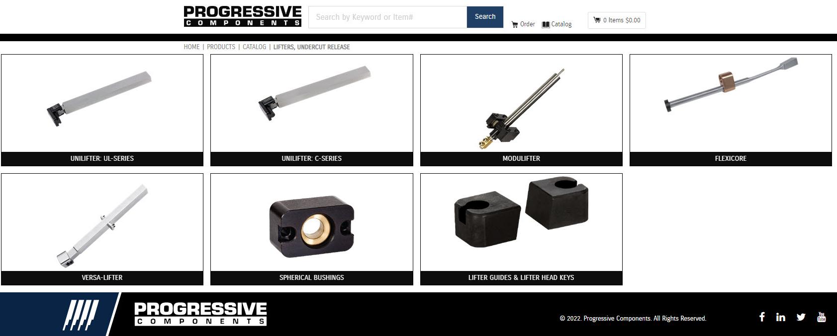
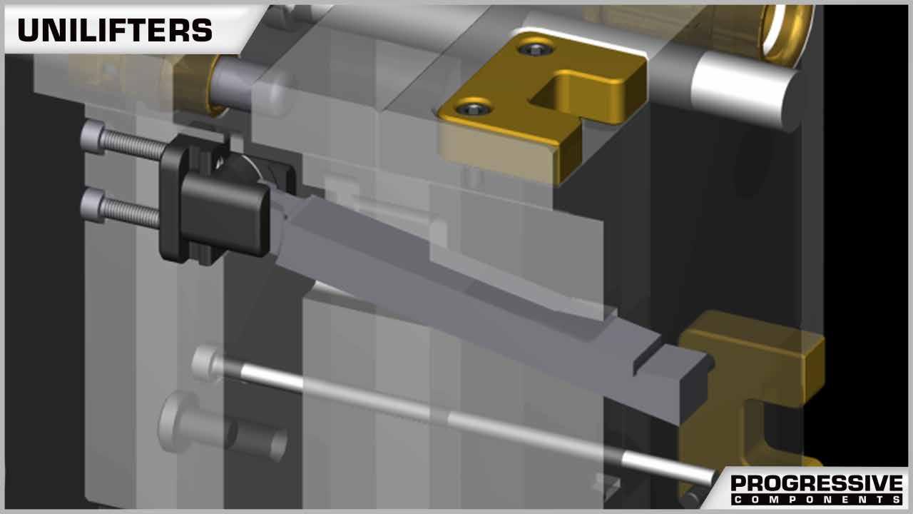
CAD geometry is available online as individual downloads or as part of the CADalog system. The seven formats include: IGES (.igs), ACIS (.sat), STEP (.step), Parasolid (.x_t), SolidWorks (.sldasm), NX (.prt) (Re-Use and MoldWizard) and Visi (.wkf).
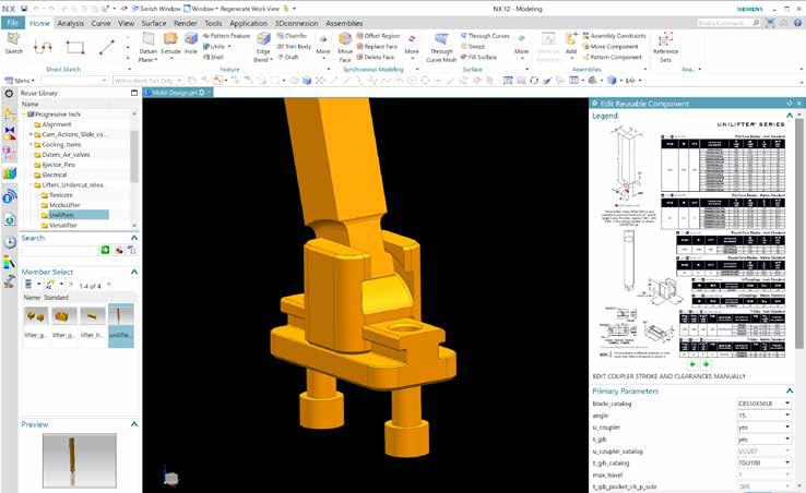
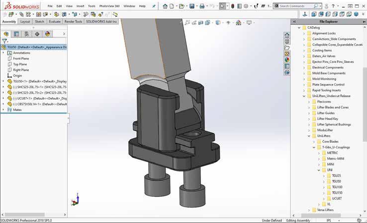
LIFTERS, UNDERCUT RELEASE H-24
Industry-leading web store expedites the purchasing process. Go to shop.procomps.com for information and additional resources.
COLLAPSIBLE CORES EXPANDABLE CAVITIES
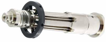
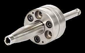
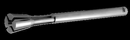
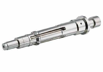
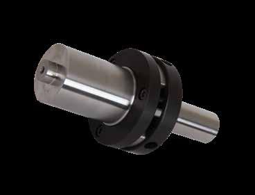
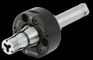
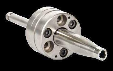
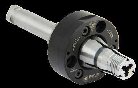
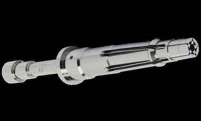
SECTION I
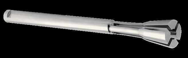 DT Core Sub-10mm Series
Prefix: DT
Prefix: S10
Page: I-7
RT Core Grinding Rings
Expandable Cavities
Prefix: RTGR
Prefix: EXCAV Page: I-11 Page: I-12
DT Core Sub-10mm Series
Prefix: DT
Prefix: S10
Page: I-7
RT Core Grinding Rings
Expandable Cavities
Prefix: RTGR
Prefix: EXCAV Page: I-11 Page: I-12
Through an alliance with Roehr Tool Solutions, Dove Tail Collapsible Cores offer a more compact design and simplified mold approach over other tool designs. Available in four standard sizes and also as customs, DT Series Collapsible Cores eliminate the need for complex unscrewing mechanisms as well as providing solutions for unmoldable internal undercut features such as o-ring grooves, slots, and snap fit details.
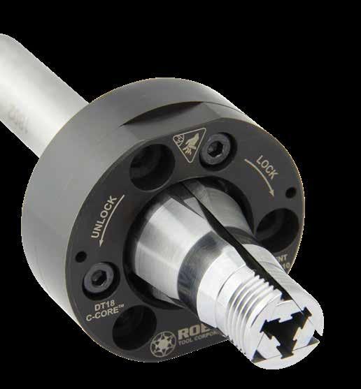
DT Cores allow for:
• Simplified, smaller molds
• Faster cycle times
• Improved part quality
• Reduced mold maintenance
• Existing unscrewing molds can see performance improvements by converting the movable half to instead include DT Cores.
The DT Collapsible Core is a positive, mechanically actuated collapsible core that eliminates complex gear and rack approaches, resulting in a simpler mold and a faster cycle time. The maintenance advantage is dramatic due to a patented quick-lock feature that allows removal and servicing of the core unit while the mold is still in the press. The DT Core’s compact design allows for shorter stack height, tighter cavity spacing, and also creates opportunities for use in slides or on the stationary side of the mold.
DT Cores use a simple single stage collapse/eject sequence typically run by the machine knock out.
COLLAPSIBLE CORES, EXPANDABLE CAVITIES I-1
COLLAPSIBLE CORES DT SERIES
DT Core Mold
Unscrewing Mold
Initial Opening Undercut Release Part Ejects COLLAPSE EJECT
US Patent Nos. 8,033, 810 & 9,011,138 issued and others pending.
COLLAPSIBLE CORES, EXPANDABLE CAVITIES
COLLAPSIBLE CORES DT SERIES
For sizes larger than 60mm, contact Roehr.
I-2
CATALOG NUMBER D MAXIMUM OUTER DIAMETER U MAX UNDERCUT L MAXIMUM MOLDING LENGTH ST MAXIMUM COLLAPSE STROKE H CORE LENGTH SD SHAFT DIA. BD COOLING HOLE DIA. BH DISTANCE TO COOLING HOLE SL SHAFT LENGTH CD CARRIER DIA. CT CARRIER ASSEMBLY THICKNESS BC MOUNTING SCREW BOLT CIRCLE T SHCS DT1010 10.00-10.99mm .394-.433in .36mm .014in 7.5mm .295in 43.5mm 1.713in 87mm 3.425in 10.5mm .413in 3mm .1in 5mm .2in 58mm 2.283in 50mm 1.969in 21mm .827in 37mm 1.457in M5 x 25 DT1111 11.00-11.99mm .433-.472in .41mm .016in 8mm .315in 44.5mm 1.752in DT1212 12.00-12.99mm .472-.511in .46mm .018in 8.5mm .335in 45.5mm 1.791in 87mm 3.425in 12mm .472in 4mm .2in 5mm .2in 59mm 2.323in 52mm 2.047in 21mm .827in 38mm 1.496in M6 x 35 DT1313 13.00-13.99mm .512-.551in .51mm .020in 9mm .354in 46.5mm 1.831in DT1414 14.00-14.99mm .551-.590in .56mm .022in 9.5mm .374in 47mm 1.850in 87mm 3.425in 14mm .551in 5mm .2in 5mm .2in 60mm 2.362in 54mm 2.126in 21mm .827in 41mm 1.614in M5x25 DT1515 15.00-15.99mm .591-.630in .61mm .024in 10mm .394in 47.5mm 1.870in DT1616 16.00-16.99mm .630-.669in .66mm .026in 10.5mm .413in 48mm 1.890in 87mm 3.425in 15.5mm .610in 6mm .2in 5mm .2in 62mm 2.441in 56mm 2.205in 21mm .827in 43mm 1.693in M5x25 DT1717 17.00-17.99mm .669-.708in .71mm .028in 11mm .433in 48.5mm 1.909in DT1819 18.00-19.99mm .709-.787in .82mm .032in 12mm .472in 50mm 1.969in 99mm 3.898in 18mm .709in 8mm .3in 6mm .2in 61mm 2.402in 63mm 2.480in 24mm .945in 49mm 1.929in M6x30 DT2021 20.00-21.99mm .787-.866in .92mm .036in 12.5mm .492in 55mm 2.165in DT2224 22.00-24.99mm .866-.984in 1.04mm .041in 13mm .512in 59mm 2.323in 109mm 4.291in 22mm .866in 10mm .4in 6mm .2in 64mm 2.520in 69mm 2.717in 24mm .945in 55mm 2.165in M6x30 DT2527 25.00-27.99mm .984-1.102in 1.20mm .047in 15mm .591in 66.5mm 2.618in DT2830 28.00-30.99mm 1.102-1.220in 1.36mm .053in 18mm .709in 71mm 2.795in 129mm 5.079in 28mm 1.102in 12mm .5in 6mm .2in 60mm 2.362in 77mm 3.031in 26mm 1.024in 63mm 2.480in M6x30 DT3133 31.00-33.99mm 1.220-1.338in 1.50mm .059in 21mm .827in 78mm 3.071in DT3436 34.00-36.99mm 1.339-1.456in 1.73mm .068in 22mm .866in 79mm 3.110in 139mm 5.472in 34mm 1.339in 14mm .6in 6mm .2in 64mm 2.520in 93mm 3.661in 27mm 1.063in 75mm 2.953in M8x30 DT3739 37.00-39.99mm 1.457-1.574in 1.88mm .074in 24mm .945in 85mm 3.346in DT4042 40.00-42.99mm 1.575-1.693in 2.06mm .081in 25mm .984in 86mm 3.386in 151mm 5.945in 39mm 1.535in 17mm .7in 6mm .2in 65mm 2.559in 101mm 3.976in 32mm 1.260in 83mm 3.268in M8x35 DT4345 43.00-45.99mm 1.693-1.811in 2.24mm .088in 27mm 1.063in 93mm 3.661in DT4648 46.00-48.99mm 1.811-1.929in 2.42mm .095in 28mm 1.102in 94mm 3.701in 161mm 6.339in 42mm 1.654in 20mm .8in 6mm .2in 69mm 2.717in 110mm 4.331in 32mm 1.260in 90mm 3.543in M8x35 DT4951 49.00-51.99mm 1.929-2.047in 2.57mm .101in 31mm 1.220in 99mm 3.898in DT5254 52.00-54.99mm 2.047-2.165in 2.77mm .109in 32mm 1.260in 100mm 3.937in 183mm 7.205in 50mm 1.969in 22mm .9in 6mm .2in 85mm 3.346in 130mm 5.118in 39mm 1.535in 107mm 4.213in M10x45 DT5557 55.00-57.99mm 2.165-2.283in 2.95mm .116in 34mm 1.339in 106mm 4.173in DT5860 58.00-60.99mm 2.283-2.401in 3.10mm .122in 36mm 1.417in 111mm 4.370in L D U CD 120° TYP BC T (3) 25° H SL CT SD BH BD ST US Patent Nos. 8,033, 810 & 9,011,138 issued and others pending.
Utilizing the optional Quick Lock mounting configuration, the DT Core can be removed and serviced while the mold remains in the press. This feature allows for a higher cavitation percentage and lower maintenance costs than other tool design approaches.
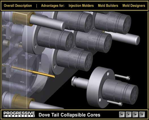
COLLAPSIBLE CORES DT SERIES QUICK LOCK PLATE
Align and push end of Center Pin through Quick Lock Plate.
View the ability to remove a core from parting line at
Rotate Center Pin clockwise 90° to lock into place.
COLLAPSIBLE CORES, EXPANDABLE CAVITIES I-3
CATALOG NUMBER GD QL +.00 - .05 QW +.00 - .05 QS1 QS2 H B MOUNTING SCREWS DTQLP1011 7.43mm .93in 26.01mm 1.024in 18.01mm .709in 17.50mm .689in 9.50mm .374in 4mm .1575in M3 LHCS DTQLP1213 9.02mm .355in 27.99mm 1.102in 18.01mm .709in 19.51mm .768in 9.50mm .374in 4mm .1575in M3 LHCS DTQLP1415 9.81mm .386in 30mm 1.181in 19.99mm .787in 21.49mm .846in 11.51mm .453in 5mm .1969in M3 LHCS DTQLP1617 10.60mm .417in 32mm 1.260in 22mm .866in 23.50mm .925in 13.49mm .531in 5mm .1969in M3 SHCS DTQLP1821 12.99mm .511in 35mm 1.378in 24.99mm .984in 24.99mm .984in 15.01mm .591in 6mm .2362in M4 SHCS DTQLP2227 16.16mm .636in 38mm 1.496in 27.99mm 1.102in 27.99mm 1.102in 18.01mm .709in 6mm .2362in M4 SHCS DTQLP2833 21.72mm .855in 43.99mm 1.732in 32mm 1.260in 34.01mm 1.339in 22mm .866in 6mm .2362in M4 SHCS DTQLP3439 25.69mm 1.011in 51.99mm 2.047in 40.01mm 1.575in 40.01mm 1.575in 27.99mm 1.102in 8mm .3150in M5 SHCS DTQLP4045 30.45mm 1.199in 56.01mm 2.205in 43.99mm 1.732in 43.99mm 1.732in 32mm 1.260in 8mm .3150in M5 SHCS DTQLP4651 34.42mm 1.355in 57.99mm 2.283in 46mm 1.811in 46mm 1.811in 34.01mm 1.339in 8mm .3150in M5 SHCS DTQLP5260 39.18mm 1.543in 65.99mm 2.598in 54mm 2.126in 53.01mm 2.087in 41mm 1.614in 10mm ..3937in M6 SHCS DTQLP18 12mm .472in 35mm 1.378in 22mm .866in 25mm .984in 12mm .472in 6mm .236in M4 SHCS DTQLP28 15mm .591in 38mm .1.496in 25mm .984in 28mm 1.102in 15mm .591in 6mm .236in M4 SHCS DTQLP38 19mm .748in 41mm 1.614in 31mm 1.220in 30mm 1.181in 20mm .787in 6mm .236in M4 SHCS DTQLP48 23mm .906in 44mm 1.732in 35mm 1.378in 34mm 1.339in 25mm .984in 6mm .236in M4 SHCS
QS2 GD QW QL QS1 6 Shaft Length (SL) +.01 +.03 Groove Diameter ±.05 H 4 R Location of plate groove determined by mold design Shaft Diameter (SD) Shaft Diameter (SD) Flats are tangent to GD US Patent Nos. 8,033, 810 & 9,011,138 issued and others pending.
Bottom view of Center Pin and Quick Lock Plate in locked position.
procomps.com.
M A-2 H 54-57 HRC
COLLAPSIBLE CORES, EXPANDABLE CAVITIES
COLLAPSIBLE CORES
DT SERIES SPLIT RING
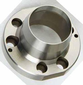
Utilizing the optional split ring allows for an alternative attachment method.
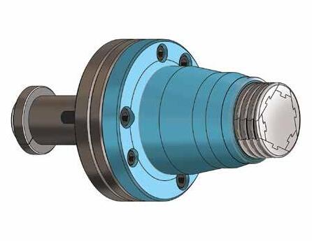
Assemble Core into Mold. Then collapse core to install split ring
Push Center Pin forward to molding position and install back plate
DT SERIES RETENTION SLEEVE
Retention Sleeves for DoveTail Collapsible Cores assure the position of the molded part during core collapse and part ejection.
I-4
CATALOG NUMBER A OUTER DIAMETER B INNER DIAMETER C THICKNESS DTSR1011 16mm .63in 7.95mm .313in 3.99mm .157in DTSR1213 17.53mm .69in 9.53mm .375in 3.99mm .157in DTSR1415 20.32mm .80in 10.31mm .406in 5mm .197in DTSR1617 21.08mm .83in 11.13mm .438in 5mm .197in DTSR1821 25.40mm 1.00in 13.49mm .531in 5.99mm .236in DTSR2227 28.70mm 1.13in 16.66mm .656in 5.99mm .236in DTSR2833 34.29mm 1.35in 22.23mm .875in 5.99mm .236in DTSR3439 42.16mm 1.66in 26.19mm 1.031in 8mm .315in DTSR4045 46.99mm 1.85in 30.96mm 1.219in 8mm .315in DTSR4651 50.80mm 2.00in 34.93mm 1.375in 8mm .315in DTSR5260 59.69mm 2.35in 39.70mm 1.563in 9.98mm .393in DTSR18 24.89mm .98in 12.70mm .500in 6.35mm .250in DTSR28 27.94mm 1.10in 15.88mm .625in 6.35mm .250in DTSR38 34.80mm 1.37in 20.62mm .812in 6.35mm .250in DTSR48 37.59mm 1.48in 25.40mm 1.000in 6.35mm .250in A A B C
US Patent Nos. 8,033, 810 & 9,011,138 issued and others pending.
Collapsible Core Molded Part Retention Sleeve Carrier Top Ring
M A-2 H 54-57 HRC
M D-2 H 60-62 HRC
COLLAPSIBLE CORES DT SERIES
APPLICATION GUIDELINES
• All standard DT Cores offer 360˚ molding of threads or other undercuts.
• Molded parts do not need to be closed at one end. They may be partially or completely open.
• In the chart above, the actual collapse is dependent upon the final major diameter ground onto DT core. Please email information@roehrtool.com for an application review prior to ordering the DT Cores.
• Stripper ring can be provided by moldmaker with either a tapered or straight fit, as shown in the machining guidelines at right.
• Parts with size requirements that fall outside of the standard sizes are available on a custom order basis.
• Roehr Tool can provide DT Cores with your thread and undercut details already machined. In addition, coatings and treatments may also be provided. Email your part drawing or application to information@roehrtool.com for a review.
• Each Dove Tail Collapsible Core includes:
-DT Series Core/Pin/Carrier Assembly
-Split Ring
-All mounting screws
COLLAPSIBLE CORES, EXPANDABLE CAVITIES I-5
C CD D BC T (3) ML CT S SL L B BD BH SD QS2 GD QW QL QS1 6 Shaft Length (SL) +.01 +.03 Groove Diameter ±.05 6 M4 x 10 SHCS 4 R Location of plate groove determined by mold design 60˚ grinding center provided on both ends. (Grind to suit.) Flats for in-press servicing 120˚ (Typ.) 10˚ Stroke Shaft Diameter (SD) Shaft Diameter (SD) Flats are tangent to GD CATALOG NUMBER D MAXIMUM OUTER DIAMETER B MINIMUM INNER DIAMETER +3°/SIDE ML MAXIMUM MOLDING LENGTH C MAXIMUM COLLAPSE CD CARRIER DIAMETER +0.00 - 0.05 CT CARRIER ASSEMBLY THICKNESS ± 0.05 L CORE LENGTH +0.1 - 0.0 SL SHAFT LENGTH SD SHAFT DIAMETER +0.00 - 0.02 BD COOLING HOLE DIAMETER BH DISTANCE TO COOLING HOLE BC MOUNTING SCREW BOLT CIRCLE T SCREWS S MAXIMUM COLLAPSE STROKE DT18 21mm .827in 17mm .669in 22mm .866in 1.1mm .043in 53mm 2.087in 21mm .827in 60mm 2.362in 60mm 2.362in 16mm .630in 6mm .236in 6mm .236in 40mm 1.575in M5 x 25 34mm 1.339in DT28 33mm 1.299in 25mm .984in 28mm 1.102in 1.6mm .063in 60mm 2.362in 22mm .866in 67mm 2.638in 60mm 2.362in 20mm .787in 8mm .315in 8mm .315in 47mm 1.850in M5 x 25 38mm 1.496in DT38 42mm 1.654in 33mm 1.299in 43mm 1.693in 2.1mm .083in 76mm 2.992in 28mm 1.102in 85mm 3.346in 60mm 2.362in 25mm .984in 10mm .394in 10mm .394in 60mm 2.362in M6 x 35 54mm 2.126in DT48 54mm 2.126in 42mm 1.654in 50mm 1.969in 2.4mm .094in 98mm 3.858in 37mm 1.457in 104mm 4.094in 70mm 2.756in 30mm 1.181in 12mm .472in 12mm .472in 78mm 3.071in M8 x 40 62mm 2.441in D +1.5 CT +0.5 Determines Assembly Location D +1.5 6 4 Min. Stripper Ring CD +.1 SD SD +0.5 +.05 -.00 CD +1.5 Moldbase Clearance CAD insertion point US Patent Nos. 8,033, 810 & 9,011,138 issued and others pending.
COLLAPSIBLE CORES, EXPANDABLE CAVITIES
COLLAPSIBLE CORES DT SERIES OVERVIEW
Dove Tail Center Pin
Collapsing Segments
Typical thread or undercut details to be released by core
Collapsing Segments
• Designed to mechanically collapse when the center pin is withdrawn.
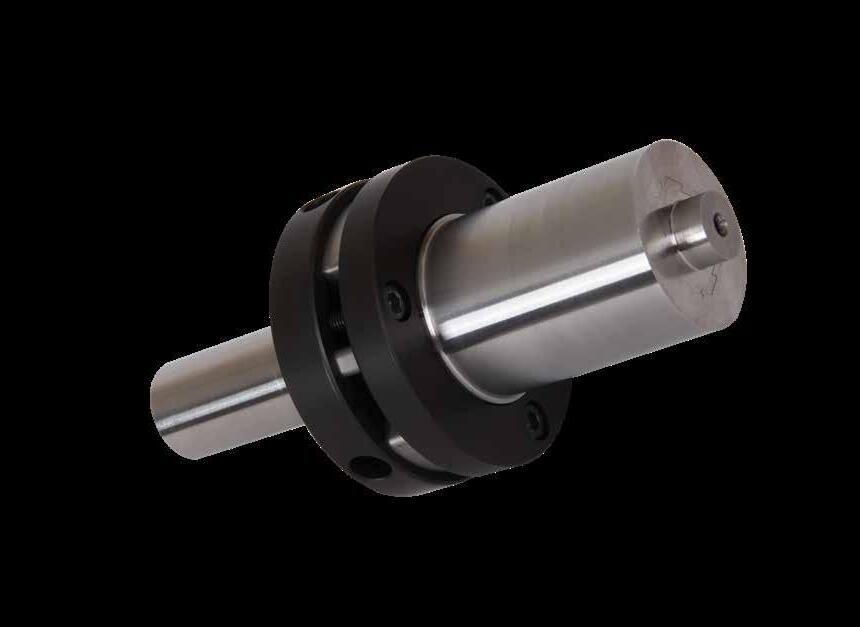
• The fit between the segments is controlled to permit flash-free molding.
Center Pin
Carrier Assembly
• Serves to expand the segments of the core to their molding position
• The pin may be flush to the core face.
Carrier Assembly
• Mounts DT Core assembly to the mold carrier plate.
• Provides guided and anti-rotational segment movement.
Quick Lock Plate or Split Ring
I-6
CATALOG NUMBER CORE SIZE DTGF1011 DT1011 DTGF1213 DT1213 DTGF1415 DT1415 DTGF1617 DT1617 DTGF1821 DT1821 DTGF2227 DT2227 DTGF2833 DT2833 DTGF3439 DT3439 DTGF4045 DT4045 DTGF4651 DT4651 DTGF5260 DT5260 CATALOG NUMBER CORE SIZE DTGF18 DT18 DTGF28 DT28 DTGF38 DT38 DTGF48 DT48 US Patent Nos. 8,033, 810 & 9,011,138 issued and others pending. M A-2 H 54-57 HRC M D-2 H 60-62 HRC M D-2 H 60-62 HRC M A-2 H 54-57 HRC S Black Oxide
The Sub-10mm DT Cores make it possible to release very small threads and undercuts in molded caps, connectors and small medical applications.
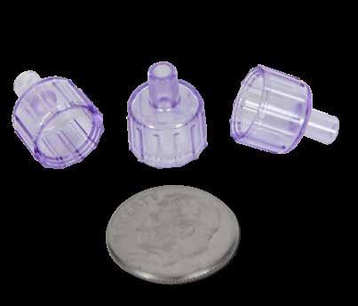
• Allows molding of parts with 7-10mm ID.
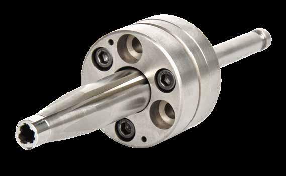
• Quick Lock plates enable core removal from parting line.
• Simpler alternative to unscrewing molds.
• Reduces cycle time and maintenance requirements.
COLLAPSIBLE CORES DT CORE SUB-10MM SERIES
NOTE: Submit part geometry to information@roehrtool.com for quotes and application review.
APPLICATION GUIDELINES
• Maximum undercut depth is determined by final molding diameter from application review.
• Collapse stroke is determined by undercut depth from application review.
• Cores are supplied complete with machined molding details.
COLLAPSIBLE CORES, EXPANDABLE CAVITIES I-7
CATALOG NUMBER MD MAXIMUM MOLDING DIAMETER ID MINIMUM MOLDING DIAMETER ML MAXIMUM MOLDING LENGTH UC MAXIMUM UNDERCUT CD CARRIER ASSEMBLY DIAMETER CB CARRIER ASSEMBLY BODY CT CARRIER ASSEMBLY THICKNESS L LENGTH SL SHAFT LENGTH SD SHAFT DIAMETER S MAXIMUM COLLAPSE STROKE BD COOLING HOLE DIAMETER BH COOLING HOLE HEIGHT BC MOUNTING BOLT CIRCLE T MOUNTING BOLT (3) S10-Custom 10 7 10 .38 44 19 24 82 36 8 50 3 3 32 M5x25 Eject
Collapse Stroke
CD ML BH MD L SL SD BD CT ID CB S BC T(3) US Patent Nos. 8,033, 810 & 9,011,138 issued and others pending.
COLLAPSIBLE CORES, EXPANDABLE CAVITIES
COLLAPSIBLE
CORES DT SERIES APPLICATIONS
Side Action
Cavity Side
Boss Detail
Seal Ring
I-8
US Patent Nos. 8,033, 810 & 9,011,138 issued and others pending
The RT Series Collapsible Cores are available in sizes to fit most inside detail applications. Whether molding threads or complex details, these cores can simplify design and production. Collapsible Cores allow for smaller molds to run faster cycles with less moving parts.
Standard sized Collapsible Cores (RT) and MiniCores (RT) are engineered and manufactured for Progressive Components through an alliance with Roehr Tool Solutions.
Standard diameters range from 13mm to 105mm.
Part Ejected Cylinders push the stripper plate forward, ejecting the molded part.
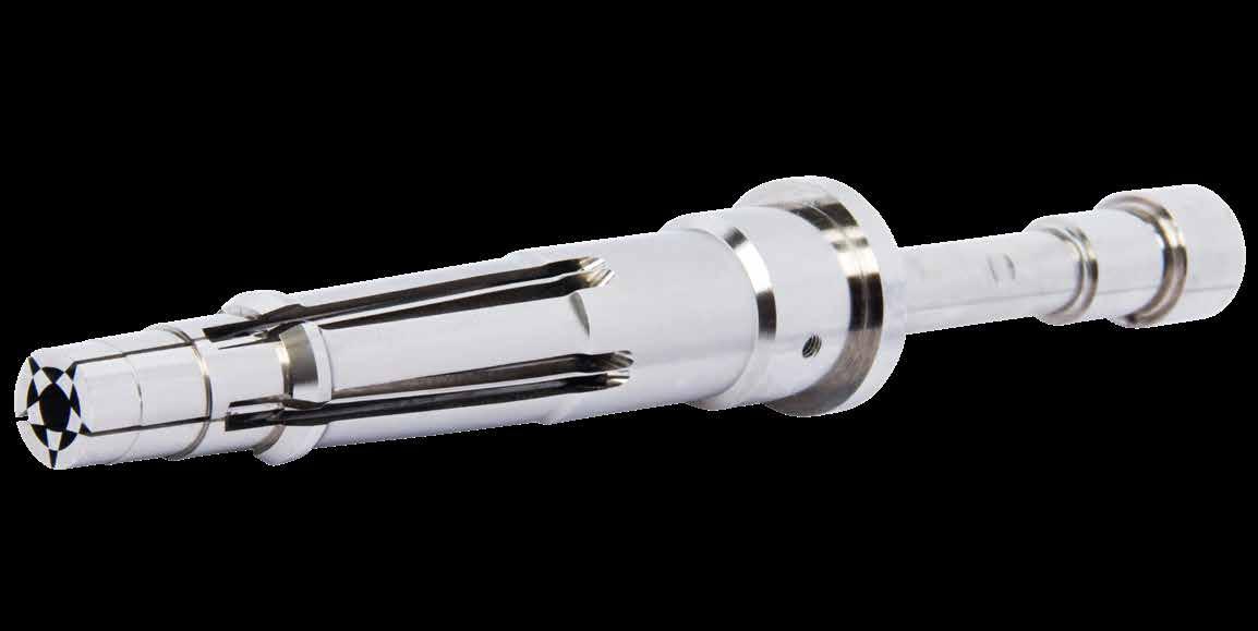
COLLAPSIBLE CORES, EXPANDABLE CAVITIES I-9
COLLAPSIBLE CORES & MINICORES ® RT SERIES
Made from premium tool steels and heat treated using proprietary heat treating methods.
1 Mold Open Ejector plate and stripper plate move forward, and the Collapsible Core is collapsed.
2 Mold Closed
3
COLLAPSIBLE CORES, EXPANDABLE CAVITIES
I-10
RT SERIES C B ML L 150.8mm (5.940”) A C B ML L A C B A CATALOG NUMBER A MAXIMUM OUTER DIAMETER B MINIMUM INNER DIAMETER CENTER PIN DIAMETER (AT TOP OF COLLAPSIBLE CORE) ML MAX. MOLDED LENGTH (INCLUDING MOLD SHUT-OFF) C COLLAPSE PER SIDE AT TOP OF CORE** (RANGE SHOWN) L LENGTH OF COLLAPSIBLE CORE INCH MM INCH MM INCH MM INCH MM INCH MM INCH MM INCH MM CC-125-PC .720 18.29 .620 15.75 .485 12.32 .800 20.32 .027 .69 .032 .81 5.605 142.37 CC-150-PC .850 21.59 .700 17.78 .580 14.73 1.000 25.40 .037 .94 .042 1.07 6.615 168.02 CC-175-PC .970 24.64 .760 19.30 .640 16.25 1.000 25.40 .043 1.09 .048 1.21 6.615 168.02 CC-200-PC 1.270 32.25 .910 23.11 .785 19.93 1.150 29.21 .043 1.09 .048 1.21 7.315 185.80 CC-250-PC 1.270 32.25 .910 23.11 .785 19.93 1.150 29.21 .043 1.09 .048 1.21 5.440 138.17 CC-202-PC 1.390 35.30 1.010 25.65 .885 22.47 1.150 29.21 .055 1.39 .064 1.62 7.315 185.80 CC-252-PC 1.390 35.30 1.010 25.65 .885 22.47 1.150 29.21 .055 1.39 .064 1.62 5.440 138.17 CC-302-PC 1.740 44.19 1.270 32.25 1.105 28.06 1.400 35.56 .068 1.72 .083 2.10 7.315 185.80 CC-352-PC 1.740 44.19 1.270 32.25 1.105 28.06 1.400 35.56 .068 1.72 .083 2.10 6.065 154.05 CC-402-PC 2.182 55.42 1.593 40.46 1.388 35.25 1.700 43.18 .090 2.28 .103 2.61 7.815 198.50 CC-502-PC 2.800 71.12 2.060 52.32 1.750 44.45 1.900 48.26 .115 2.92 .125 3.17 9.625 244.47 CC-602-PC 3.535 89.78 2.610 66.29 2.175 55.24 2.400 60.96 .140 3.55 .148 3.75 11.250 285.75 CC-652-PC 3.800 96.52 2.890 73.41 2.450 62.23 2.400 60.96 .150 3.81 .160 4.06 11.250 285.75 CC-702-PC 4.225 107.31 3.350 85.09 2.790 70.86 2.400 60.96 .165 4.19 .170 4.32 11.250 285.75 CATALOG NUMBER FOR CLOSURE DIAMETER RANGE A MAXIMUM OUTER DIAMETER B MINIMUM INNER DIAMETER CENTER PIN DIAMETER (AT TOP OF COLLAPSIBLE CORE) WIDTH OF (3) NON-COLLAPSING CENTER PIN BLADES (AT TOP OF CORE) ML MAX. MOLDED LENGTH (INCLUDING MOLD SHUT-OFF) C COLLAPSE PER SIDE AT TOP OF CORE MM Inch MM Inch MM Inch MM Inch MM Inch MM Inch MM CCM-0001 13-16 .645 16.38 .425 10.80 .300 7.62 .170 4.32 .850 21.59 .052 1.32 CCM-0002 17-20 .805 20.45 .560 14.22 .420 10.67 .190 4.83 .850 21.59 .057 1.45 CCM-0003 21-24 .965 24.51 .710 18.03 .560 14.22 .200 5.08 1.000 25.40 .059 1.50 MINICORES ® RT SERIES C B ML L 150.8mm (5.940”) A C B ML L A C B A CAD insertion point
COLLAPSIBLE CORES
COLLAPSIBLE CORES & MINICORES ® RT SERIES
Description of Components and Basic Operation
Both styles of the Collapsible Cores (Standard and MiniCores®) are three-part assemblies, designed for simplicity of installation, reliability in operation, and long life. The three parts include a Collapsible Core, a Positive Collapse Sleeve, and a Center Pin.
Center Pin
Collapsible Core
• Designed to collapse independently when the center pin is withdrawn.
• The fit between segments is controlled to permit flash-free molding.
Collapsible Core
Positive Collapse Sleeve
Positive Collapse Sleeve
• Designed to function when the Collapsible Core fails to collapse independently. In normal operation, the PC Sleeve is not functioning. It is essential to have such a unit for maximum safety and reliability in automatic and semi-automatic operation.
Center Pin
• Serves to expand the segments of the Collapsible Core to their molding position.
• The pin must protrude beyond the face of the collapsing core segments, and it must have a radius around its top edge to operate properly.
APPLICATION GUIDELINES
• Standard Collapsible Cores have a Max. OD (“A”) of thread or configuration ranging from .720”(18.29mm) - 4.225” (107.31mm) and offer complete 360˚ thread or undercut geometry.
• MiniCores have a Max. OD of thread or configuration ranging from .645”(16.38mm) - .965”(24.51mm) and offer up to 70% full thread or undercut geometry. (Internal geometry is interrupted in three places to allow core segments to collapse.)
• Molded parts do not need to be closed at one end. They can be partially or completely open. Also, undercuts do not need to be continuous.
• Cores are capable of operating without benefit of lubrication, however, treating the Collapsible Core with an additional treatment for wear reduction or corrosion resistance is beneficial.
• Custom cores with size requirements that fall outside of the standard Collapsible Core and MiniCore ranges are available. In addition, finished cores with machined, EDM’d, or ground details can be supplied. Contact information@roehrtool.com for an application review.
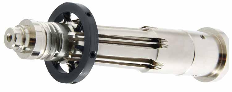
RT CORE GRINDING RINGS
Grinding Rings for Collapsible Cores securely hold the core segments in place against the center pin when grinding or EDM’ing details.
COLLAPSIBLE CORES, EXPANDABLE CAVITIES
CATALOG NUMBER CORE SIZE (PREFIX CC) RTGR125 125 RTGR150 150/175 RTGR200 175/200/202/250/252 RTGR300 302/352 RTGR400 402 RTGR500 502 RTGR600 602 RTGR650 652 RTGR700 702
M A-2 H 54-57 HRC
M Aluminum H Black Anodize
M D-2 H 60-62 HRC
M 52100 H 54-57 HRC
EXPANDABLE CAVITIES EX-CAV ® SYSTEM
Expandable Cavities mold undercuts such as threads, dimples, and protrusions.
The patented Ex-Cav design eliminates the engineering, maintenance, and machining required for side action mechanisms which results in smaller molds or higher mold cavitation.
Standard sized Expandable Cavities (Ex-Cavs) are engineered and manufactured for Progressive Components through an alliance with Roehr Tool Solutions.
APPLICATION GUIDELINES
• Four sizes offered to satisfy a wide range of parts.
• The Ex-Cav expands along a conical shape, 10˚ per side.
• Manufactured from A-2, 54-57 HRC material for repeatable expansion. For optimal performance, the Ex-Cavs should ride against a hardened insert.
• Maximum temperature: 500˚F (260°C)
• Expandable Cavities are capable of operating without lubrication.
• However, treating the Ex-Cav with an additional coating for wear reduction or corrosion resistance is beneficial.
• Ex-Cavs can be ordered with molding detail for a ‘mold ready’ component.
• Fixturing bushings for machining details in house are also available.
• Custom Ex-Cavs are available. Also, when an entire part is formed within the cavity, an A-Series Ex-Cav can be provided, shown at right.
COLLAPSIBLE CORES, EXPANDABLE CAVITIES I-12
X Minimum Ejector Stroke X Minimum Ejector Stroke
Closed US Patent No. 8,038,433
Mold
Mold Open
EXPANDABLE CAVITIES EX-CAV ® SYSTEM
Mounting kits sold separately below. Ex-Cav sizes outside of this chart are available as customs.
Hollow Bolt Mounting Kit Includes:
• Key (7 Thk. x 8 x 40)
• Hollowed Bolt
• Standard DIN H-13 Ejector Pin (400mm Long)
• Spacer
MOUNTING KITS & MACHINING SPECS
Pin Bolt Mounting Kit Includes:
• Key (7 Thk. x 8 x 40)
• Threaded Bolt/Pin (H-13, 40-44 HRC, 280mm Long)
• Spacer
COLLAPSIBLE CORES, EXPANDABLE CAVITIES I-13
US Patent No. 8,038,433
EX-CAV NUMBER D PIN DIAM. ±.05 T BOLT THREAD SPACER SIZE (IDxODxThk) D2 PIN BOLT KIT NUMBER EXCAV20 6.0 M8-1.25 8x22x4 14 EXC20BP EXCAV26 7.7 M10-1.5 10x23x4 16 EXC26BP EXCAV38 14.5 M18-2.5 19x33x6 27 EXC38BP EXCAV50 19.8 M24-3 25x42x6 34 EXC50BP B A C D C E S T 125 10˚ (Conical) 250 ± 1.0 g7 ±.01 Length can be modified to suit application. Expansion per side L ± 1.0 E S T 125 10˚ (Conical) 250 ± 1.0 g7 Length can be modified to suit application. Expansion per side L ± 1.0 D D2 T Modified to suit +.025 +.050 Key Spacer Core Pin Retainer (Sold separately) D2 D T +.025 +.050 Key Spacer Modified to suit
Replacement DIN Ejector Pins are sold on page A-4. Core Pin Retainers are sold on page A-18. CATALOG NUMBER D EX-CAV DIA. A MAXIMUM PART DIA, -10˚ PER SIDE B MAXIMUM MOLDING LENGTH C MINIMUM PART INNER DIA. E EXPANSION PER SIDE F MIN. WALL THICKNESS L S BODY DIA. T X MINIMUM EJECTION STROKE (PREV. PAGE) EXCAV20 2O 14 13 2.5 1.6 3 59 14 M8 15 EXCAV26 26 18 20 3.5 2.5 4 76 16 M10 15 EXCAV38 38 30 27 4.0 3.0 4 89 27 M18 20 EXCAV50 50 40 39 5.5 3.5 5 101 34 M24 20
B F .05 Min Clearance EX-CAV NUMBER D NOMINAL PIN DIA. T BOLT SIZE SPACER SIZE (IDxODxThk) D2 HOLLOW BOLT KIT NUMBER EXCAV20 3.5 M8-1.25 x 40 8x22x4 14 EXC20BH EXCAV26 4 M10-1.5 x 40 10x23x4 16 EXC26BH EXCAV38 10 M18-2.5 x 50 19x33x6 27 EXC38BH EXCAV50 14 M24-3 x 55 25x42x6 34 EXC50BH B A C D C E S T 125 10˚ (Conical) 250 ± 1.0 g7 ±.01 Length can be modified to suit application. Expansion per side L ± 1.0 CAD insertion point M A-2 H 54-57 HRC
ONLINE RESOURCES
When considering design options, numerous animations can be viewed at procomps.com.
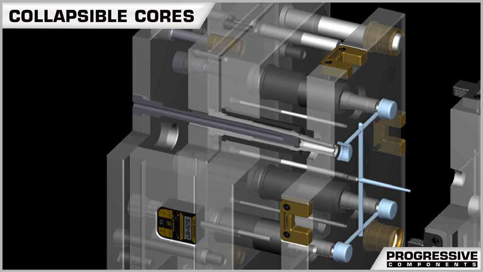
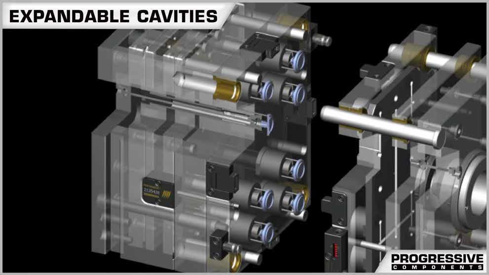
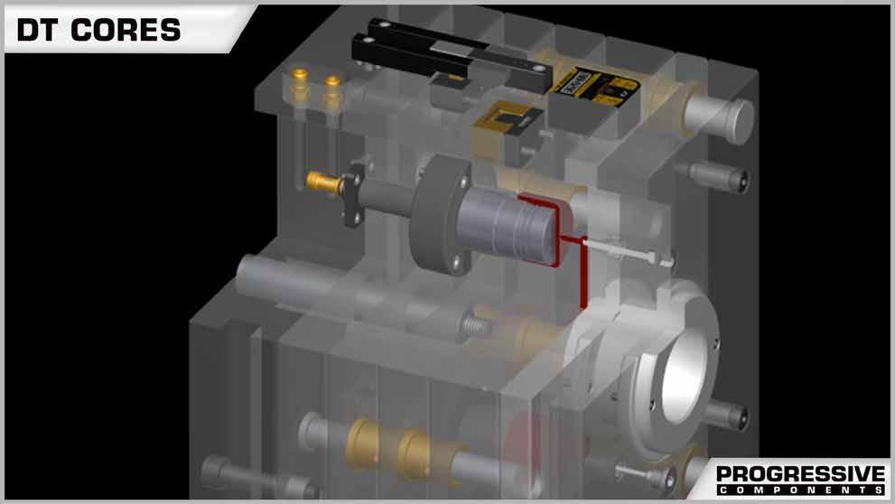
I-14
COLLAPSIBLE CORES, EXPANDABLE CAVITIES
PLATE SEQUENCE CONTROL
SECTION J
Plate Latch Locks: Cam Sequencing
Prefix: PLC, PLCM
Page: J-1
Plate Retainers
Prefix: PRT
Page: J-8
Plate Accelerators
Prefix: ACCPM
Page: J-13
Plate Latch Locks: Cam Block Seq. Roller Pullers
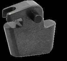
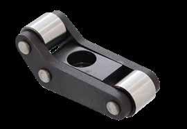
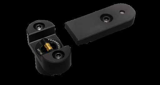

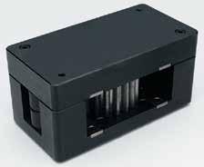

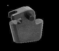
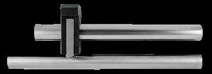
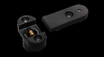
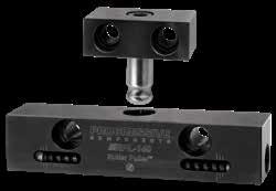
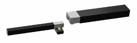
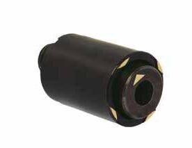
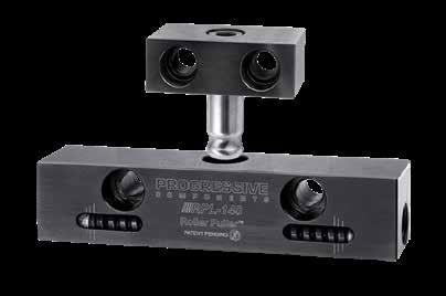

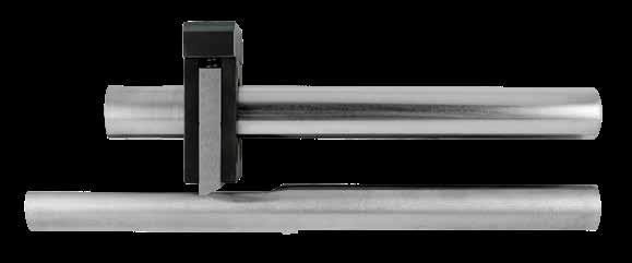
Prefix: PLN
Page: J-5
Two-Stage Ejectors
Prefix: PLN
Page: J-10
Friction Pullers
Prefix: FP
Page: J-14
Prefix: RPL
Page: J-7
Ejector Accelerators
Prefix: EJA
Page: J-12
StacKit System
Prefix: SK
Page: J-15 - J-18
Mold Closed: Lock Engaged
In this 3-plate application, three parting lines are utilized for ejecting the part and runner.
PLATE LATCH LOCKS
First Parting Line Opens
The Puller Pin pulls the runner and breaks the gate, while parting line #3 is held closed by the Latch Lock.
Stroke Continues
After stripper bolts crossing parting line #2 and #3 bottom out, the Wedge Block is fully disengaged from Latch Bar.
Main Parting Line Opens
With both parting line stripper bolts bottomed out and the Latch Bar released, parting line #3 is free to open.
APPLICATION GUIDELINES
• The 7”/180mm assemblies are suggested for pulling 2,000 lbs (900 kg) each and the 12”/300mm assemblies are suggested for pulling 3,000 lbs (1360 kg) each. Weight ratings may vary based on gate size, friction conditions, and velocity.
• On molds that are 12” wide or more, Progressive recommends four assemblies, two sets per side on the opposite ends of the mold.
• Using four assemblies with the addition of four Stripper Plate Kits (-S version) to push plates is recommended for plates 12” or greater in width.
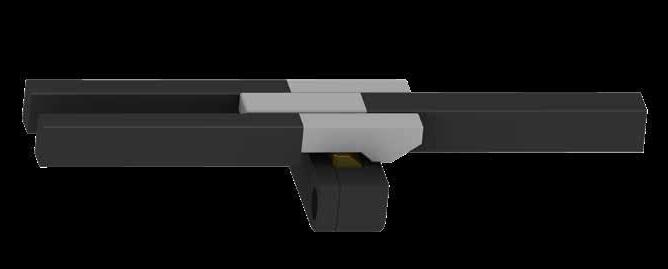
PLATE SEQUENCE CONTROL J-1
1 2 L2 L1 P P PL3 L2 L1 P P PL3 L2 L1 P P PL3 L2 L1 P P PL3 L2 L1 P P PL3 L2 L1 P P PL3 L2 L1 P P PL3 L2 L1 P P PL3 L2 L1 P P PL3 L2 L1 P P PL3 L2 L1 P P PL3 L2 L1 P P PL3 L2 L1 P P PL3 L2 L1 P P PL3 L2 L1 P P PL3 L2 L1 P P PL3 4 3 3
PLATE LATCH LOCKS 3-PLATE APPLICATION
Design & Installation:
1. Determine Latch travel.
2. Determine Stripper Bolt travel, .06 minimum clearance past Latch release.
3. Determine the Cam Bar length by utilizing the gauge pin and timing diagram on the opposite page.
4. Machine the Latch Bar so that with the mold closed there is .001” clearance between the Wedge Block and Latch Bar as shown in the timing diagram.
5. Machine (2) counterbores and (2) dowel holes for Latch and Cam Bar as shown. Two (2) dowels are recommended for proper alignment.
7”/180mm Latch/Cam Bar Length Installation
6. For all assemblies, the Wedge Block Assembly is installed according to the pocket dimensions below.
7. For the 12”/300mm assemblies, the Guide Block must be installed over the Latch and Cam Bars. The Guide Block will help to avoid deflection, causing latch timing issues, during production and can be purchased for optional use on the 7”/180mm assemblies. Screw size and locations are shown below, and it is suggested that location is on the center of the Wedge Block Assembly pocket, opposite the spring pressure.
8. Max operating temperature is 500°F (260°C).
12”/300mm Latch/Cam Bar Length Installation
Inch Standard
Metric Standard
J-2
PLATE SEQUENCE CONTROL
CATALOG NUMBER A +.001 -.000 B ± .005 C ± .005 D +.001 -.000 E +.001 -.000 F ± .005 G REF J L M R POCKET X ± .005 Y ± .005 THD PLC75-7 3.001 2.44 .45 .900 1.000 1.31 1.80 .750 .750 .500 .250 3.625 .500 1/4-20 x .50 Deep PLC75-12 CATALOG NUMBER A +.03 - .00 B ± .1 C ± .1 D +.03 - .00 E +.03 - .00 F ± .1 G REF J L M R POCKET X ± .1 Y ± .1 THD PLCM20-180 80.02 64 12 24 27 35 49 20 20 14 7 92 13.5 M6-1.0 x 10mm Deep PLCM20-300
Machine for (2) SHCS and (2) Dowels as shown Machine Cam Bars to clear Wedge for length of plate. Provided Length = 7” (180mm) Provided Length = 7” (180mm) L J D E M G F Machine for (2) SHCS and (2) Dowels as shown Total combined Stripper Bolt travel must equal Latch Bar travel +.06" (1.5mm) minimum for clearance. L2 L1 P P L3 (Main) P Guide Block Provided Length = 12” (300mm) Provided Length = 12” (300mm) L J D E M G F PL2 L3 (Main) P PL1 CAD insertion point A X Guide Block = .75 / 19mm C R THD D E Y B THD
Wedge Block Assembly Installation Guide Block Installation
For Cam Bar Release Point
PLATE LATCH LOCKS TIMING
Latch Bar Cam Bar .260 (8mm) Full Release Latch Bar Cam Bar .260 (8.20mm) Full Release 3
Dual Ejection
Once engaged, the Latch Bar starts to fall off the lead-in to the Wedge Block, allowing separation of parting line #3 to begin.
Release Point “T”= Stripper Plate Travel + .212 (6.66mm) Provided Length = 7.5”
Plate Latch Locks keep both ejector sets together until the release point. The Wedge Block Assembly would be installed in the bottom ejector plate, following the installation of all components.
APPLICATION GUIDELINES
• Stripper plate applications can be utilized as shown above with the optional Stripper Plate Kit as sold on page J-4. The Latch Bar will be discarded and replaced with the Driver, Cap, and Spacer offered in the kit.
T
Latch Bar is disengaged from Wedge Block.
APPLICATIONS
Provided Length= 7.5” (193mm)
Stripper Plate
The Drivers push the stripper plate forward until the parts are stripped from the core. The lock then releases, allowing the ejector pins to push the parts from the stripper plate.
• All pocket and component machining is similar to the 3-plate application shown on page J-2 except for calculation of the “T” dimension for timing the release point according to the graphic at right.
T = Full Release: .270” (7.50mm) from bottom of Wedge Block to tangent of pin. .001 (.03mm) gap between Driver Cap & Wedge Block required Stripper .001 (.03mm) Gap between Driver Cap & Wedge Block Required
• Use the Spacer as a template for machining the bolts/dowels on the Driver/Cap assembly.
• Attach the Spacer to the Driver, which will provide .03”(.75mm) gap between the Driver and the mold to avoid interference.
Stripper
.01” (.25mm) Clearance between Wedge Block and Cam Bar T Gauge Pin: .500” or 14mm Dia.
PLATE SEQUENCE CONTROL J-3
Gauge Pin: Ø.5000 (Ø14mm)
Latch Bar Latch Bar Cam Bar Cam Bar Latch Bar Cam Bar Wedge Block .740 (16mm) .260 (8mm) Parting Line Closed Initial Release Full Release Latch Bar Cam Bar .260 (8.20mm) Full Release .001” (.03mm) gap between the Wedge Block and Latch Bar when the mold is closed Ø.5000 (Ø14mm) gauge pin tangent to Cam Bar Latch Bar Cam Bar Wedge Block .740 (15.8mm) Parting Line Closed .001” (.03mm) gap between the Wedge Block and Latch Bar when the mold is closed Ø.5000 (Ø14mm) gauge pin tangent to Cam Bar 1 2 Latch Bar Latch Bar Cam Bar Cam Bar Latch Bar Cam Bar Wedge Block .740 (16mm) .260 (8mm) Parting Line Closed Initial Release Full Release Latch Bar Cam Bar .260 (8.20mm) Full Release .001” (.03mm) gap between the Wedge Block and Latch Bar when the mold is closed Ø.5000 (Ø14mm) gauge pin tangent to Cam Bar Latch Bar Cam Bar Wedge Block .740 (15.8mm) Parting Line Closed .001” (.03mm) gap between the Wedge Block and Latch Bar when the mold is closed Ø.5000 (Ø14mm) gauge pin tangent to Cam Bar Latch Bar Latch Bar Cam Bar Cam Bar Latch Bar Cam Bar Wedge Block .740 (16mm) .260 (8mm) Parting Line Closed Initial Release Full Release Bar .260 (8.20mm) Release .001” (.03mm) gap between the Wedge Block and Latch Bar when the mold is closed Ø.5000 (Ø14mm) gauge pin tangent to Cam Bar Latch Bar Cam Bar Wedge Block .740 (15.8mm) Parting Line Closed .001” (.03mm) gap between the Wedge Block and Latch Bar when the mold is closed Ø.5000 (Ø14mm) gauge pin tangent to Cam Bar Latch Bar Cam Bar .260 (8mm) Full Release Latch Bar Cam Bar .260 (8.20mm) Full Release Latch Bar Cam Bar Wedge Block .740 (15.8mm) .001” (.03mm) gap between the Wedge Block and Latch Bar when the mold is closed Ø.5000 (Ø14mm) gauge pin tangent to Cam Bar
The Latch Bar is set up for 1.0” (24mm) of travel to full release.
PLATE LATCH LOCKS CAM SEQUENCING
PLC75-7 7.0
PLC75-12 12.0
PLCM20-180 180mm
PLCM20-300 300mm
Assemblies include:
• All machined components listed below.
• Items within the Wedge Block Assembly:
- Compression Springs (2)
- 1/4-20 LHCS or M6-1.0 LHCS (2 per assembly)
- 1/8 or 3mm Diameter Dowel Pin (1 per assembly)
• Screws within the Guide Block (12”/300mm assemblies) - 1/4-20 LHCS or M6-1.0 LHCS (2 per assembly)
PART NAME
MATERIAL/TREATMENT
Latch Bar 4340, 35-40 HRC, Nitride/Black Oxide
Cam Bars (2) 4340, 35-40 HRC, Nitride/Black Oxide
Wedge Block: A-2, 58-60 HRC
Titanium Nitride
Wedge Block Assembly
Guide & Guide Plate: H-13, 52-54 HRC
Nitride/Black Oxide
Guide Block H-13, 52-54 HRC, Nitride/Black Oxide
The Guide Block may also be utilized on the 7”/180mm assemblies. To order the assembly which includes screws, specify PLC75-GBA for inch standard and PLCM20-GBA for metric.

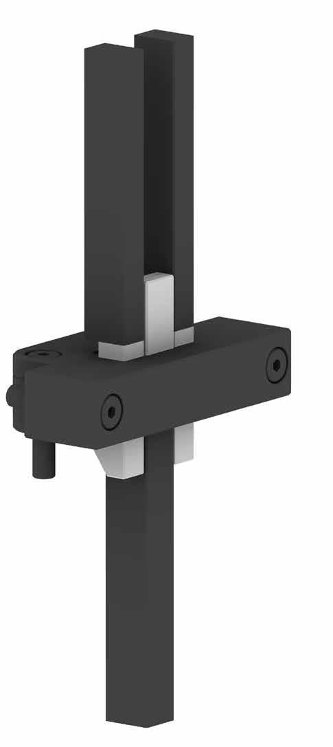
PLATE LATCH LOCKS STRIPPER PLATE KIT
For stripper plate applications, purchase the appropriate metric or inch assembly from the top of the page and the matching kit below. The mold maker will discard the Latch Bar, replacing it with the Cap/Driver/Spacer shown at right.
CATALOG NUMBER STANDARD
PLC75-S Inch
PLCM20-S Metric
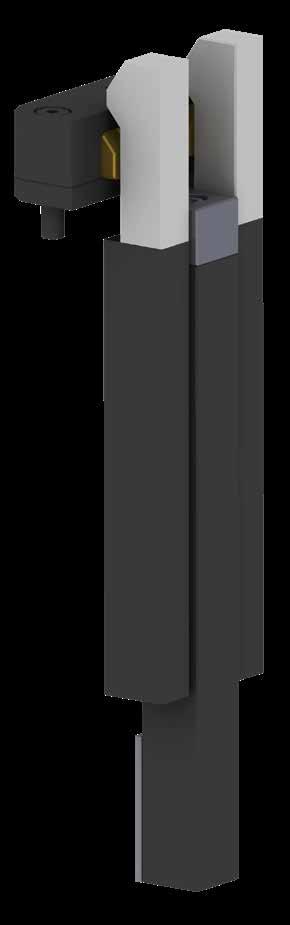
Assembly includes:
• All machined components listed below.
• (1) #10-32 x .75 or M5-.8 x 30mm SHCS
PART NAME MATERIAL/TREATMENT
Cap 4340, 35-40 HRC, Nitride
Driver 4140, 28-35 HRC, Black Oxide
Spacer 303 Stainless Steel, 35-40 HRC
Cam Bars and Wedge Block Assembly are shown for reference only, sold separately within the assembly above.
Cap
Driver
PLATE SEQUENCE CONTROL J-4
Guide Block
CATALOG NUMBER LATCH/CAM BAR LENGTHS
Spacer
ASSEMBLY
Latch Bar
Wedge Block Assembly
Cam Bars (2)
PLATE LATCH LOCKS CAM BLOCK SEQUENCING
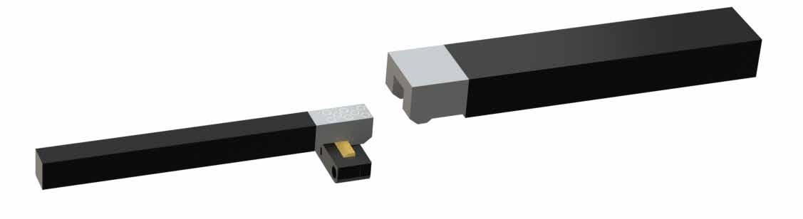
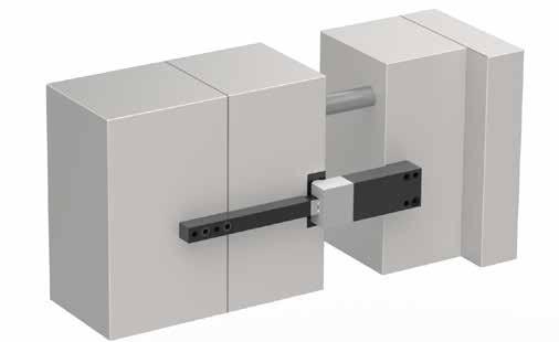
PLATE SEQUENCE CONTROL J-5
US Patent No. 7,963,758 European Patent No. 2442955 1 L2 L1 P PL2 P PL1 G L K D E Machine for (2) SHCS and (2) Dowels as shown Machine for (2) SHCS and (2) Dowels as shown F J Provided Length = 16” (400mm) Provided Length = 16” (400mm) 2 L2 L1 P PL2 PL2 P PL1 PL1 G L K D E Machine for (2) SHCS and (2) Dowels as shown Machine for (2) SHCS and (2) Dowels as shown F J .06” (1.5mm) gap after Latch release Provided Length = 16” (400mm) Provided Length = 16” (400mm) 3 PL2 PL2 PL1 PL1 G L K D F J .06” (1.5mm) gap after Latch release Provided Length = 16” (400mm) Provided Length = 16” (400mm) A X Guide Block = .75 / 19mm C R THD D E Y B THD CATALOG NUMBER A +.001 -.000 B ± .005 C ± .005 D +.001 -.000 E +.001 -.000 F ± .005 G REF J K L R POCKET THD PLC125-16 4.001 3.25 .45 .900 1.500 2.00 2.875 1.875 1.250 1.125 .250 5/16-18 CATALOG NUMBER A +.03 - .00 B ± .1 C ± .1 D +.03 - .00 E +.03 - .00 F ± .1 G REF J K L R POCKET THD PLCM32-400 100 82 12 24 36 50 75 47 32 28 7 M8-1.25 Inch Standard Metric Standard Refer to page J-6 for design and installation guidelines. Mold Closed: Lock Engaged First Parting Line Opens Mold Open Wedge Block Assembly Installation
PLATE LATCH LOCKS TIMING
The Latch Bar is set up for 1.0” (24mm) of travel to full release.
Once engaged, the Latch Bar starts to fall off the lead-in to the Wedge Block, allowing separation of parting line to begin.
APPLICATION GUIDELINES
• Recommended pulling limit is 6,000 lbs (2,700kg) each.
• Determine the Cam Bar length by utilizing the gauge pin and timing diagram.
• Machine the Latch Bar so that with the mold closed there is .001” (.03mm) clearance between the Wedge Block and Latch Bar as shown in the timing diagram.
• Machine (2) counterbores and (2) dowels for Latch and Cam Bar as shown on page J-5. Two (2) dowels are recommended for proper alignment.
• Max operating temperature is 500°F (260°C)
Latch Bar is disengaged from Wedge Block.
Assemblies include:
• All machined components listed below.
• Items within the Wedge Block Assembly:
- Compression Springs (2)
- 5/16-18 x 1.75” SHCS or M8-1.25 x 40mm SHCS (2)
- 1/8 Diameter Dowel Pin (1)
Latch Bar 4340, 35-40 HRC, Nitride/Black Oxide
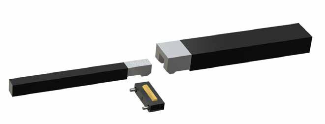
Cam Bar 4340, 35-40 HRC, Nitride/Black Oxide
Wedge Block Assembly
Wedge Block: A-2, 58-60 HRC Titanium Nitride
Guide & Guide Plate: H-13, 52-54 HRC
Nitride/Black Oxide
J-6
PLATE SEQUENCE CONTROL
For Cam Bar Release Point 1 Latch Bar Cam Bar Wedge Block .740 (15.8mm) Parting Line Closed .001” (.03mm) gap between the Wedge Block and Latch Bar when the mold is closed Ø.5000 (Ø14mm) gauge pin tangent to Cam Bar 2 Latch Bar Latch Bar Cam Bar Cam Bar Latch Bar Cam Bar Wedge Block .740 (16mm) Parting Line Closed Initial Release Latch Bar Cam Bar .001” (.03mm) gap between the Wedge Block and Latch Bar when the mold is closed Ø.5000 (Ø14mm) gauge pin tangent to Cam Bar Latch Bar Cam Bar Wedge Block .740 (15.8mm) Parting Line Closed .001” (.03mm) gap between the Wedge Block and Latch Bar when the mold is closed Ø.5000 (Ø14mm) gauge pin tangent to Cam Bar Latch Bar Latch Bar Cam Bar Latch Bar Cam Bar Wedge Block .740 (16mm) (8mm) Parting Line Closed Initial Release .260 (8.20mm) Release .001” (.03mm) gap between the Wedge Block and Latch Bar when the mold is closed Ø.5000 (Ø14mm) gauge pin tangent to Cam Bar Latch Bar Cam Bar Wedge Block .740 (15.8mm) Parting Line Closed .001” (.03mm) gap between the Wedge Block and Latch Bar when the mold is closed Ø.5000 (Ø14mm) gauge pin tangent to Cam Bar 3 Cam Bar Latch Bar Cam Bar .260 (8.20mm) Full Release Latch Bar Cam Bar .260 (8mm) Full Release Latch Bar Cam Bar .260 (8.20mm) Full Release Latch Bar Cam Bar .740 (15.8mm) when the mold is closed Ø.5000 (Ø14mm) gauge pin tangent to Cam Bar
PART NAME MATERIAL/TREATMENT
L2 L1 P P PL3 L1 L2 P P PL1 Stripper Plate Support Plate Cavity Plate Cavity Plate Core Plate Core Plate Bottom Clamp Plate Core Retainer Plate PL1 Stripper Plate Support Plate Cavity Plate Cavity Plate Core Plate Core Plate Bottom Clamp Plate Core Retainer Plate PL1 Stripper Plate Support Plate Cavity Plate Core Plate Bottom Clamp Plate Core Retainer Plate Latch Bar
Bar Wedge Block Assembly
A-Plate A-Side
Plate
Cam
Floating
Ejection Stripper
Ejection
APPLICATION GUIDELINES
• Mounting pattern matches industry standards.
• Compression screw provides adjustable pull force.
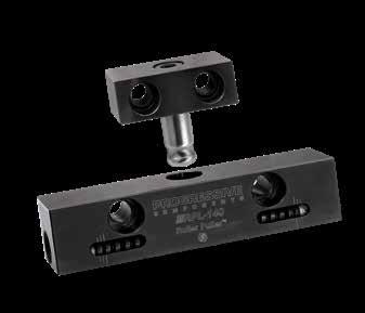
• Roller design allows for smooth action.
• Mounting screws and dowels included.
• Roller Pullers are available with special length rods to suit applications where a different distance between the housings is required. For pricing and delivery, contact tech@procomps.com with the catalog number above along with the required gap or “G” dimension.
ROLLER PULLERS ™
Pull Force
Tighten lock screws equally to achieve forces below.
PLATE SEQUENCE CONTROL J-7
CATALOG NUMBER W1 T1 W2 T2 A B G S1 S2 S3 S4 D1 D2 DOWEL DIA. SHCS PR RPL-135 135 25 38 25 28 19 1 60.0 25.0 7.0 15.6 30.0 22.1 5 M6-1.0 x 25 26 RPL-135-40 135 25 38 25 28 19 40 60.0 25.0 7.0 54.6 30.0 61.1 5 M6-1.0 x 25 65 RPL-140 140 32 64 25 32 22 2 70.0 35.0 10.0 23.1 100.0 28.1 6 M10-1.5 x 35 30 RPL-140-40 140 32 64 25 32 22 38 70.0 35.0 10.0 59.3 100.0 64.3 6 M10-1.5 x 35 66 PR Roller Housing Roller Spring Housing Lock Screw Compression Screw Pull Rod Mold Closed PR Pull Rod Mold Open
CATALOG NUMBER RPL-135 45 Kg (100 lbs) 75 Kg (160 lbs) 100 Kg (220 lbs) RPL-135-40 45 Kg (100 lbs) 75 Kg (160 lbs) 100 Kg (220 lbs) RPL-140 45 Kg (100 lbs) 100 Kg (220 lbs) 150 Kg (330 lbs) RPL-140-40 45 Kg (100 lbs) 100 Kg (220 lbs) 150 Kg (330 lbs) CAD insertion point Pull Rod: M M-2 H 62-64 HRC, Nitrided Roller: M M-2 H 62-64 HRC, Nitrided Housing: M 4140 H 27-32 HRC S Black Oxide S2 W2 T2 T1 S1 D1 W1 S3 S4 D2 Dowel (4) 8mm SHCS (4) A B G S1 D1 Screw and dowel orientation for RPL-140 and RPL-140-40 S2 W2 T2 T1 S1 D1 W1 S3 S4 D2 Dowel (4) 8mm SHCS (4) A B G S1 D1 Screw and dowel orientation for RPL-140 and RPL-140-40
PLATE SEQUENCE CONTROL
PLATE RETAINERS
The Plate Retainer is designed to hold parting lines or retain plates for sequence functions. The Plate Retainer can also be used in conjunction with other latch components to ensure desired sequencing.
• Incorporates the SRT Slide Retainer for greaseless retention.
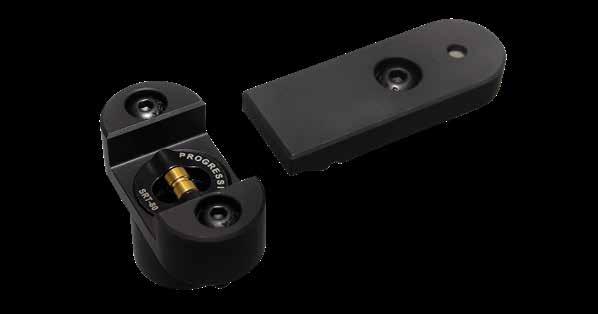
Floating A-Plate Application
Mold Closed
Plate Float
Parting line travel is controlled by the stripper bolt.
A-Plate Release
Main parting line opens.
Ejector Plate Applications
Stripper Plate Application
With a 1-3/8” (36mm) bottom clamp plate, the Plate Retainer can be used to retain ejector plates in the molding position.
The Plate Retainer can also retain the pin plates in position at the end of a ejector stroke.
The Plate Retainer can be used to keep stripper plates in molding position during mold open.
J-8
2 3 1 PL1 L2 (Main) P PL1 L2 (Main) P PL1 L2 (Main) P 1-3/8” (36mm) 1-3/8” (36mm) PL1 PL2 (Main) PL1 L2 (Main) P PL1 L2 (Main) P PL1 L2 (Main) P PL1 L2 (Main) P
US Patent Nos. 7,229,269 & 7,431,581, with other patents issued and pending
Screws, dowels, and Slide Retainer are included.
APPLICATION GUIDELINES
• The holding force rating for the PRT80-260 is 80 lbs and the PRTM36-64 is 36 kgs.
• It is recommended that four (4) Plate Retainer assemblies are installed, two (2) on each side of the tool, when using to pull plate weights up to 300lbs (120kg) or with approximate plate sizes of 20 x 28 x 1-7/8” (396 x 796 x 46mm) and 18 x 24 x 2-3/8” (346 x 696 x 66mm).
• Leader Pins must be engaged before the Retainer Bar enters the Plate Retainer housing assembly.
• Max operating temperature is 425°F (220°C).
PLATE SEQUENCE CONTROL J-9
CAD insertion point CATALOG NUMBER A B RADIUS C ± .01 D DOWEL E F +.000 - .005 G ± .01 H +.000 - .005 J +.000 - .005 K +.000 - .002 L CHAMFER M CHAMFER S1 SHCS S2 SHCS PRT80-260 1.625 .500 1.125 1/4 x 1/2 1.125 .500 .750 .750 1.500 1.000 .03 .09 1/4-20 x 5/8 #10-32 x 7/8 CATALOG NUMBER A B RADIUS C ± .25 D DOWEL E F +.00 - .13 G ± .01 H +.00 - .13 J +.00 - .13 K +.00 - .13 L CHAMFER M CHAMFER S1 SHCS S2 SHCS PRTM36-64 39 12.5 28 6 x 12 29 12 20 18 38 25 .8 2.5 M6 x 14 M6 x 20 Inch Standard Metric Standard H J E G (2) øK M L S2 (2) S1 D B B F A C .01” (.25mm) Parting Line Relief Dowel & Radius Center Radius Center Overall 2.62” (64mm) 1.35” (32mm) Overall 2.12” (54mm)
PLATE RETAINERS
Retainer Bar: M 1045 H 50-54 HRC S Black Oxide Housing: M D-2 H 50-54 HRC S Black Oxide
US Patent Nos. 7,229,269 & 7,431,581, with other patents issued and pending.
TWO STAGE EJECTORS INTERNAL PLATE LATCH
Two Stage Ejectors provide a positive, mechanical method for locking and actuating plates in molds requiring multiple ejection actions. Optionally, using the press knock-out locations, the internal ejection system can be used to actuate the ejectors after the stripper plates.
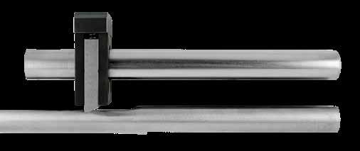
2 Mold Open: Plate Strips Part From Core Latch begins to disengage and stripper and ejector plates move forward.
APPLICATION GUIDELINES
• Engineered materials and treatments provide wear resistance during production.
• Easy installation with only a small amount of machining on plates already requiring modification.
• Simple height adjustment and timing.
• Designed to re-engage when fully retracted.
• For activating large mold plates, multiple Ejectors can be installed.
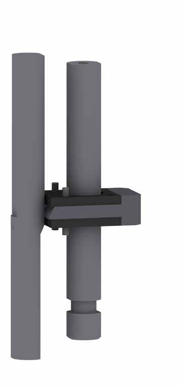
3
With the stripper plate stopped, the ejector system continues and pushes the part from the plate.
PLATE SEQUENCE
J-10
CONTROL
Mold Closed 1 Post Wear Plates (2) Locking Plate Spring Housing Release Pin
Mold Open: Part Ejected From Plate
TWO STAGE EJECTORS INTERNAL PLATE LATCH
APPLICATION GUIDELINES INSTALLATION GUIDELINES
• It is recommended that ejector rods or PKO extensions are tied into the pin plates and guided ejection is utilized.
• For small molds (12 x 20 max), one or two assemblies may be used. For molds larger than 12 x 20, four assemblies should be installed.
• On all designs, consider fastener and assembly access points and install the Latches equal distances from center to ensure proper balance of the mold.
• Determine the Post length by verifying the distance in dimension “P” according to the information above. Cut, drill, and tap the Post to suit.
• By using a .250 diameter gauge pin tangent to the flat and the angle on the Release Pin, determine the release point “T” as shown above.
• Calculate the overall length of the Release Pin and then cut, drill, and tap.
• Machine all pockets per the drawing above.
• Bolt the Release Pin and Post to the B-side plates.
• Ejector plates are then assembled with the Wear Plate, Locking Plate, and Spring Housing.
• Locking plate is retracted to allow for the temporary keeper screw installed. This allows the Locking Plate to pass over the Post and also have clearance to Release Pin.
• Ejector plates are to be installed onto guided ejector pins and placed in the proper location, lining up Locking Plate with relief in the Post.
• Finally, remove the temporary keeper screw, allowing the Locking Plate to snap into the relief within the Post.
PLATE SEQUENCE CONTROL J-11
NAME MATERIAL/TREATMENT
Plate A-2, 58-60 HRC
Plate (2) H-13 50-54 HRC, Nitrided, Black Oxide Spring Housing 4140, 28-32 HRC Release Pin 4340, 30-35 HRC, Nitrided Post 4340, 30-35 HRC, Nitrided CATALOG NUMBER DESCRIPTION PLN100 Two Stage Assembly Assembly includes:
All five machined components listed at right. • Compression Springs (2) • #10-32 LHCS (4) .188 ±.001 .188 ±.001 Cut Release Pin after verifying dimension “T” and drill & tap for 3/8-16. Drill & C’Bore for 3/8-16 SHCS (2) Provided Length = 10” 1.13 1.650 .691 1.500 .19 R (Typ.) Drill & C’Bore for #10-32 SHCS Optional sub-assembly screw location. (Remove after installing components.) Located .62 off of post center (x,y). Drill & Tap for #10-32 SHCS x .44 deep (2) in both the Pin & Ej Plates Pockets Bottom View Screws Screws 3.125 .688 Pockets in Pin & Ej Plates P T Provided Length = 8.5” 1.06ø Clearance Cut Post to maintain dimension “P” and drill & tap for 3/8-16. Cut end of pin to suit, allowing .01” clearance to bottom of mold. Optional clearance pocket 1.06ø .397 +.000 -.001 Pocket Pocket .250 +.001 -.000 .860 +.001 -.000 .901 .448 +.000 -.001 +.001 -.000 ±.005 ±.005 ±.005 1.004 +.002 -.000 1.150 1.00 .2500ø Gauge Pin 1.31 1.750 Pocket .50 Min. T = Initial Ejector Plate release - .209 Stripper Bolt Travel = Stripper Plate Travel + .08 (Minimum) Ejection Stroke Stripper Plate B Plate Support Plate See detail above See detail above Pin Plate Ej Plate Clamp Plate .791 +.001 -.000 .397 +.001 -.000 1.001 +.001 -.000 .19 R (Typ.) .901 +.001 -.000 1.001 +.001 -.000 Post Pocket Release Pin Pocket .19 R (Typ.)
PART
Locking
Wear
•
EJECTOR ACCELERATORS
M D-2 H 48-52 HRC S Black Oxide
Kicker Pin: M H-13 H 48-50 HRC, Surface 66-70 HRC
APPLICATION GUIDELINES
• Locate Stop Pin under dowel to return the Ejector Accelerator as shown in graphic. The assembly includes the Kicker Pin, but the Stop Pin is to be provided by the mold builder.
• The Kicker Pin can be replaced with a standard ejector pin for applications with a thicker pin plate.
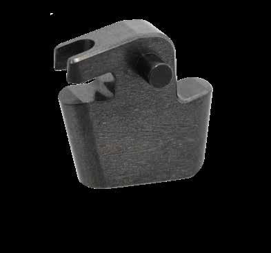
• When using spacers on the forward stroke, place spacers centerline with the Kicker Pin.
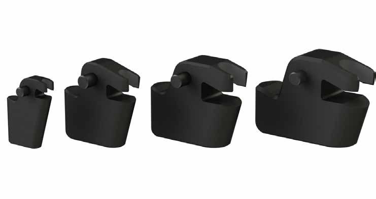
PLATE SEQUENCE CONTROL J-12
CATALOG NUMBER EP DIA. S MAX KP DIA. A B C MAX D +.001 - .000 E ± .01 W ± .01 R F M L H +.002 - .000 PP MIN Y EJA125 1/8 .110 1/8 .375 .438 .125 .188 .687 .31 .16 .28 .53 1.13 .188 .500 1.000 EJA250 1/4 .196 3/16 .625 .625 .186 .250 1.00 .50 .19 .44 .94 1.88 .250 .500 1.000 EJA375 3/8 .200 1/4 .750 .750 .186 .250 1.18 .69 .25 .50 1.13 2.25 .250 .625 1.125 EJA500 1/2 .275 3/8 .875 .875 .250 .250 1.28 .78 .25 .56 1.38 2.75 .250 .625 1.125 S C Mold Closed Mold Open CAD insertion point
Accelerator:
H L A B F Y PP M EP KP Ejector Pin Kicker Pin ØKP +.005 W R D E
PLATE ACCELERATORS
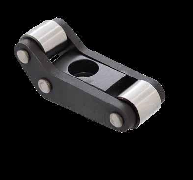
PLATE SEQUENCE CONTROL J-13
CATALOG NUMBER A L H D E F G J C N P SHCS MAX FORCE (KG/LBS) ACCPM20 20 4.4 11.6 8 9.4 11.4 6 25.8 13.2 15 Ø2.5x5 M3x12 125 / 275 ACCPM25 25 5.7 15 10 11.8 14.3 7 32.3 16 18.5 Ø3x6 M4x16 250 / 550 ACCPM37 37.5 9.1 22 15 17.7 21.5 10.5 48.5 22 25 Ø4x8 M6x25 350 / 770 ACCPM50 50 12.5 34 20 23.6 28.6 14 64.6 30 34 Ø5x10 M8x30 800 / 1,760 Screw and dowel included. CAD insertion point Arms: M H-13 H 46-50 HRC S Black Oxide Roller: M 52100 H 56-60 HRC J F G P D E A N C SHCS L H Max Max Max APPLICATION GUIDELINES • Use two or four Plate Accelerators per mold. >0 Mold Closed Mold Open
FRICTION PULLERS
PARTING LINE SEQUENCE CONTROL
Recommended interference fit is .1 to .15mm larger than the receiving hole. To adjust the Friction Puller, rotate the screw clockwise and measure bulge to achieve the proper fit. Further adjustments can be performed with 1/4 turn increments, lining up the reference arrows on the fastener to the resin.
APPLICATION GUIDELINES
• Designed to replace shoulder bolts, the Friction Pullers initiate movement and utilize friction at a particular setting to release the plate when travel limits are reached.
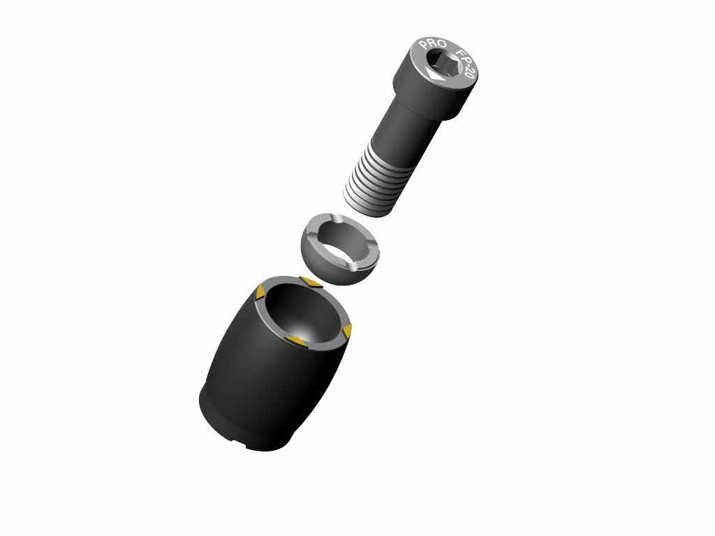
• For mold maintenance, before removing the mold from the press, rotate the screw counter-clockwise 3/4 turn. This will allow easy separation of plates.
• Maximum operating temperature is 300°F (150°C).
• Fastener includes Nylok® patch for secure installation.
• The hemisphere is plated for additional lubricity during adjustments.
• Friction Pullers are self-venting. Additional venting not required when using blind holes.
• Replacement items are available. Contact Customer Service for more information.
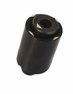
PLATE SEQUENCE
J-14
CONTROL
Mold Closed Mold Open L T PL PL D D D D D HD 2mm R Hole finish = µ Ra .4-1.6 3mm 10mm Minimum H Receiving Hole Diameter D +.10mm +.15mm Interference Adjusted on Friction Puller Floating Plate or Insert L T PL PL D D D D D HD 2mm R Hole finish = µ Ra .4-1.6 3mm 10mm Minimum H Receiving Hole Diameter D +.10mm +.15mm Interference Adjusted on Friction Puller Floating Plate or Insert
CATALOG NUMBER D L T H HEX HD HOLE DEPTH MAXIMUM FORCE (EA) (KG/LBS) FP-10 10 17 M5-.8 3 20 32.5 / 70 FP-13 13 20 M6-1 4 23 62.5 / 135 FP-16 16 25 M8-1.25 5 30 150 / 330 FP-20 20 28 M10-1.5 6 32 212.5 / 470 L T PL PL D D D D D HD 2mm R Hole finish = µ Ra .4-1.6 3mm 10mm Minimum H Receiving Hole Diameter Arrows indicate uniform setting D +.10mm +.15mm Interference Adjusted on Friction Puller Floating Plate or Insert M CAD insertion point
Fastener Hemisphere Resin
Custom PPA Resin with 8620 Fastener
STACKIT ® STACK MOLD SYSTEM
Center Positioning
Gear Housing Assembly maintains the position of the center section and protects gears and bearings from the molding elements.
Rack Spacers
Used for securing the gear racks to the movable halves.
*Mounting Pocket Dimensions +.05 / -.00
APPLICATION GUIDELINES
• Max center section effective weight per StacKit pair is 4,536kg (10,000lbs)
• Ensure mold is within maximum projected weight of molding machine.
• When mounting racks to a mold, ensure both sides are timed equally.
• Install two gear housings in center, as shown above. For large molds, four housings should be installed, two per side.
Gear Housing Top
Cam Followers (4)
Steel Spur Gear, 5 Diametral Pitch, 20 teeth, 20˚ Pressure Angle
Precision Heavy Duty Ball Bearings (2)
Wear Plates (4) to ride against racks secured by M8-1.25 FHCS
M10-1.5mm SHCS (8)
Cover Plates (4) Corner Block
CATALOG NUMBER
SK-GHA-250
Tie Bar Pads
Standard Tie Bar Pads are available with or without a machined radius or lubrication passages.
Ejection Actuation
Standard cylinders for actuating ejector plates, with standard couplings to eliminate any threading into plates.
Cam Shaft (2) Spur Gear Shaft
M12-1.75 mounting screws (4)
Steel Bushings
DESCRIPTION
Gear Housing Assembly
SK-SPRGRKIT Spur Gear Replacement Kit
The Spur Gear Replacement Kit contains (1) Spur Gear, (1) Cam Shaft, (2) Ball Bearings, (2) Thrust Washers, and (2) Steel Bushings.
PLATE SEQUENCE CONTROL J-15
84mm (3.307") 275mm (10.827")
140mm (5.512") 100mm (3.937") 128mm (5.04")
6mm (.236")
Gear Housing Bottom Thrust Washers
125.00mm* (4.96") 150.00mm* (5.91") 13mm x 45˚
Locating Pad
STACKIT ® RACK SPACERS
STACKIT ® RACKS
PLATE SEQUENCE CONTROL J-16
1240mm ± 5mm (49") 63.5mm (2.50") 1124mm (44.25") Distance between centers Actual dowel location to be determined by toolmaker 19mm (.748") Centerline of Dowel Pin M10 (.394") Dowel Pin Hole 38.1mm (1.50") 70mm (2.756") 50mm (1.968") CL Gear Housing CL Rack Spacer 90 B 50mm (1.969") 38mm (1.496") 35mm (1.378") 57mm (2.244") 100mm (3.937") 65.15mm (2.565") to center of Gear Housing 1124mm (44.25") Max distance from Gear Housing Centerline 100mm (3.937") 13mm (.511") M12-1.75mm x 120mm SHCS (2) M10 x 120mm (.394" x 4.7") Dowel Pin keeps rack securely in position For locating in moldbase 59 ±1 HRC 18 ±2 HRC CATALOG NUMBER DESCRIPTION SK-RSA-250 Rack Spacer Assembly Screws and locating dowel included. CATALOG NUMBER DESCRIPTION SK-RC-250 Rack (Sold Individually) CAD insertion point M A-36 H Pre-Hard S Black Oxide M CRS
SK-TBP-35 Tie Bar Pad Blanks
STACKIT ® TIE BAR PADS
SK-TBP-R Tie Bar Pad with finished radius. Please specify “-R” when ordering.
SK-TBP-RG
Tie Bar Pad with finished radius, grease grooves, and zerk fitting. Please specify “-RG” when ordering.
CATALOG NUMBER
DESCRIPTION SK-TBP-35
Bar Pad Blanks (No Radius) SK-TBP-R
Bar Pads with machined radius SK-TBP-RG
PLATE SEQUENCE CONTROL J-17
Tie
Tie
grease grooves and
Sold individually. 100mm 32mm (1.26") 19mm (.748") 25mm (.984") 38mm (1.496") (3.937") 75mm (2.953") M16-2 x 18mm Deep Mounting screw locations R Tie Bar Radius Tangent Point 35mm (1.378") 25mm (.984") 38mm (1.496") R Tie Bar Radius Tangent Point 6mm
installed Grease Grooves 1.5mm x 1 mm deep Grease Groove 1mm Deep [.039"] CAD insertion point
Tie
Bar Pads with machined radius,
zerk fitting
Zerk fitting
M CA954 Solid Bronze
STACKIT ® EJECTION ACTUATION
CYLINDERS
APPLICATION GUIDELINES
PIN PLATE COUPLINGS
PLATE SEQUENCE CONTROL J-18
100mm (3.937") 80mm (3.149") 35mm (1.377") 20mm (.787") 28mm (1.102") 9mm (.354") 8mm (.314") 75mm (2.952") 76mm (2.992") M20-1.5mm Thread Male 1/4 NPT couplings (2 incl.) 125mm (4.921") 38mm (1.496") 12.5mm (.492") +.00 -.13 ±.25 +.00 -.13 +.00 -.25 +.00 -.05 6.5mm (.256") 28mm (1.102") 40mm (1.575") 24mm (.945") M20-1.5mm Thread CATALOG NUMBER DESCRIPTION SK-CYL-50 50mm Block Cylinder CATALOG NUMBER DESCRIPTION SK-PPC-20 M20-1.55mm Pin Plate Coupling M12-1.75 x 100mm Mounting SHCS (4 included) Pin Plate Coupling Ejector Plate Pin Plate 15mm (.590") Locating Slot for Key (included) 5mm (.197") Locating Slot for Key (included) 50mm Stroke +.25 - .00 +.25 - .00 15mm (.590") Key Full Radius 56mm Min. (2.205") 40mm (1.575") +.25 - .00 CAD insertion point M AISI 4140 S Black Oxide CAD insertion point
• 50mm (2”) Stroke • Rated up to 3200 psi • Temperature: 220˚F (100˚C) max • Includes (2) NPT couplings and Locating Key
ELECTRICAL


COMPONENTS
SECTION K
Hot Sprue Bushings
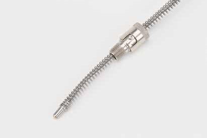
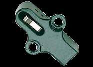
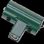
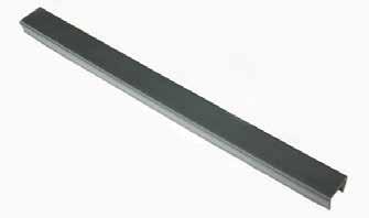
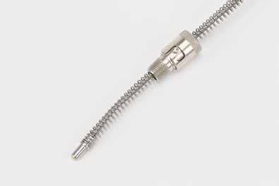
Prefix: BX Page: K-8
KO Switches External Mount Switch Side Action Switch Prefix: SWKO Page: K-1
Patch Cables Recessed Connectors Thermocouples Wire Channel Inserts Prefix: ECCA Prefix: ECRC Prefix: TC Prefix: WC Page: K-6 Page: K-7 Page: K-7 Page: K-7
Features: Color-coded, keyed for specific function. Gold-plated contacts for switching logic level signals.
Switches are wired normally open. Sealed and splash resistant.
UL/CSA rating: 5A, 250 vac
KO TM SWITCH CABLE
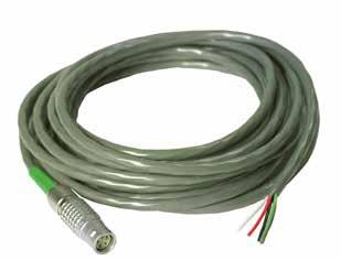
K-1
SWITCHES KO™ SWITCH
ELECTRICAL COMPONENTS CATALOG NUMBER COLOR FUNCTION SWKO-187 Green Ejection GENERAL SPECIFICATIONS FOR SWITCHES VOLTAGE 28 VDC 115 VAC 60 HZ Resistive Load 300mA min / 5A max 300mA min / 5A max Inductive Load 300mA min / 3A max 300mA min / 5A max Mechanical Life 10 million cycles 10 million cycles Max Temperature 221°F (105°C) 221°F (105°C)
CATALOG NUMBER COLOR FUNCTION ENDS LENGTH (FT) ECCA-6-20 Green Ejector Switch Male/Male 20 ECCA-6-20S Green Ejector Switch Single Male 20 CAD insertion point .250 R #10-32 x 3/8" LHCS (Included) .500 .500 .182 .875 .875 1.750
KO™ SWITCH: SINGLE EJECTOR
KO™ SWITCH: DUAL EJECTOR
K-2
ELECTRICAL COMPONENTS
CATALOG NUMBER EJ. PLATE THICKNESS COLOR FUNCTION SWKOS-100 1.000 Green Ejection SWKOS-112 1.125 Green Ejection SWKOS-118 1.187 Green Ejection CATALOG NUMBER EJ. PLATE THICKNESS RETAINER PLATE THICKNESS COLOR FUNCTION SWKOD-100 1.000 .500 Green Ejection SWKOD-112 1.125 .500 Green Ejection SWKOD-118 1.187 .500 Green Ejection .500 .875ø .182 .500 ±.002 1.562 1.125
CAD insertion point CAD insertion point .500 1.562 .875ø .182 .500 ±.002 1.125
EXTERNAL MOUNT SWITCH
ELECTRICAL COMPONENTS K-3
CATALOG NUMBER COLOR FUNCTION / CABLE PREFIX SWXM-3 Gray Enable / ECCA-3 1.500 1.125 .563 1/4-20 x 1" SHCS (2) (Included) 1.000 .500 Exter nal Mount Switch Exter nal Actuator Block #SWXB-150 shown .500 1.000 CAD insertion point
SWITCHES PLATE POSITION SWITCH
K-4
ELECTRICAL COMPONENTS
SIDE ACTION SWITCH CATALOG NUMBER COLOR FUNCTION / CABLE PREFIX SWPPS-100 Gray Enable / ECCA-3 CATALOG NUMBER COLOR FUNCTION / CABLE PREFIX SWSA-100 Gray Enable / ECCA-3 .375 .375 R (2) .750 1.250 1.000 1.000 1/4-20 X 1" SHCS (2) (Included) CAD insertion point CAD insertion point 1.000 .010 Max .45 .625 1/4-20 x 1" SHCS (2) (Included) .500 1.250 1.000 .06 Min. Between actuator arm and bottom of slide. .375 R (2) Back of slide to side action block while in open or “slide back” position.
ELECTRICAL COMPONENTS K-5 SWITCHES EXTENSION BLOCK ASSEMBLY 2.00 .25 Cut to Suit #10-32 THD .312 .375ø 1.000 .330 .180 #10-32 THD #6-32 SHCS (2) (Included) .313 .531 .688 EXTENSION BLOCK ASSEMBLY EXTENSION PIN CATALOG NUMBER DESCRIPTION SWXB-100 Extension Block Assembly SWEP-100 Extension Pin .170 1.000 .688 1.688 .625 1/4-20 x 1" SHCS (2) (Included) .500 1.250 .219 Extension Pin Extension Block Assembly .531 Side Action Switch Extension Actuator Retaining Ring Compression Spring Extension Block CAD insertion point
PATCH CABLES
ECCA-1-10CC has a 5-pin hooded connector compatible with most standard single zone controllers.

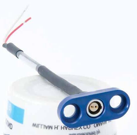
RECESSED CONNECTORS
ECCA-1-10LC connects the Hot Sprue Recessed Connector and most standard single zone controllers.
Note: As a safety precaution, the ECRC-1 for the Hot Sprues include a male plug, which is compatible with the ECCA-1-20SF female ended patch cable. Hot Sprue Bushings are sold on page K-8.

Crimp-style bullet snap connectors included.
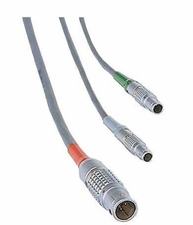
ELECTRICAL COMPONENTS K-6 CATALOG NUMBER COLOR FUNCTION PIN OUTS A B C R E F DIAMETER G DIAMETER ECRC-1 Red Hot Sprue 5 2.000 1.00 1.500 .375 1.312 .500 1.00 ECRC-3 Gray Enable 3 1.500 .625 1.000 .312 .937 .375 .625 ECRC-6 Green Ejection 4 1.500 .625 1.000 .312 .937 .375 .625 ECRC-7 Orange Stationary T/C 2 1.500 .625 1.000 .312 .937 .375 .625 ECRC-8 Blue Movable T/C 2 1.500 .625 1.000 .312 .937 .375 .625
CATALOG NUMBER COLOR FUNCTION ENDS LENGTH (FT) ECCA-1-20 Red Hot Sprue Male/Female 20 ECCA-1-20SF Red Hot Sprue Single Female 20 ECCA-1-10CC Red Hot Sprue 5 Pin M/5 Pin F 10 ECCA-1-10LC Red Hot Sprue 5 Pin M/Female 10 ECCA-3-20 Gray Enable Male/Male 20 ECCA-3-20S Gray Enable Single Male 20 ECCA-6-20 Green Ejection Male/Male 20 ECCA-6-20S Green Ejection Single Male 20 ECCA-7-20 Orange/Blue Stationary/Movable Male/Male 20 ECCA-7-20S Orange/Blue Stationary/Movable Single Male 20
E G F .250 B R A C 1/4-20 x 1/2" LHCS (2) (Included) CAD insertion point
THERMOCOUPLES
APPLICATION GUIDELINES
• Type “J”-Grounded
• 3/16” Diameter Ball Tip
• Maximum 750°F over probe
• 30” of wire included
• Maximum temperature of wire and connector: 220°F (104°C)
• Each Thermocouple assembly includes: Thermocouple, Bayonet Lock Adapter, Recessed connector, & Screws.
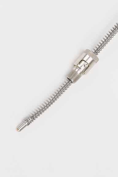
• Replacement Thermocouples (TC-100) and Bayonet Lock Adapters (TCA-100) are also available. Replacement Recessed Connectors sold on page K-6.
WIRE CHANNEL INSERTS
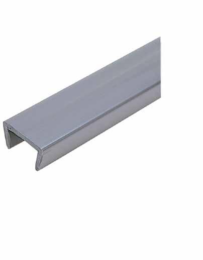
ELECTRICAL COMPONENTS K-7 CATALOG NUMBER COLOR FUNCTION / CABLE PREFIX TC-7 Orange Stationary Side TC / ECCA-7 TC-8 Blue Movable Side TC / ECCA-7 .281 Bayonet Lock Adapter (Included) .813 Adapter .313 Recessed Connector (Included) .312 R 1.500 .750 .625 .500 .250 .625 6.0 Min. Tap for 1/4-20 x 1/2" LHCS (Included) Adjust to suit 1/8-27 N.P.T. CAD insertion point CATALOG NUMBER P POCKET WIDTH H POCKET DEPTH W WIRE CHANNEL WIDTH WC-50 .550 .500 .564 ±.01 WC-100 1.000 .688 1.021 ±.02
M Nylon W P H 12" W P H 12"
HOT SPRUE BUSHINGS INCH SERIES
Progressive’s BX Inch Series Hot Sprue Bushings are designed as an advancement from previous Hot Sprue technology. This bushing’s heater design and thermocouple placement provide excellent temperature distribution and thermal stability, resulting in superior performance both at start-up and during production, increased reliability, and easier maintenance.
Existing tools will benefit by replacing cold sprues, inefficient hot sprues, or applications used to feed cold runner systems.
Engineered and manufactured for Progressive by MastipTM Technology Ltd.
To Order: Specify all options within catalog number as shown:
Radius Options:
• 1/2” Specify - 50
• 3/4” Specify - 75
Nut Options:
• Standard Length (.080) Specify - SL
• Extra Stock (+.250) Specify -XS
• Sprue Picker (+1.250) Specify - SP
Tip Options:
• Nickel-Plated Be/Cu Tip: Used for unfilled commodity thermoplastics with a maximum temperature of 570°F (300°C)
Specify -A for Nickel-Plated Be/Cu
• Carbide Tip: Ideal for engineered filled polymers with high temperature requirements. This Tungsten Carbide tip with Titanium Nitride coating was developed to process abrasive or polymers with fillers like glass, carbon, or talc.
Specify -C for Carbide Tip
Optimal thermocouple location for excellent thermal stability
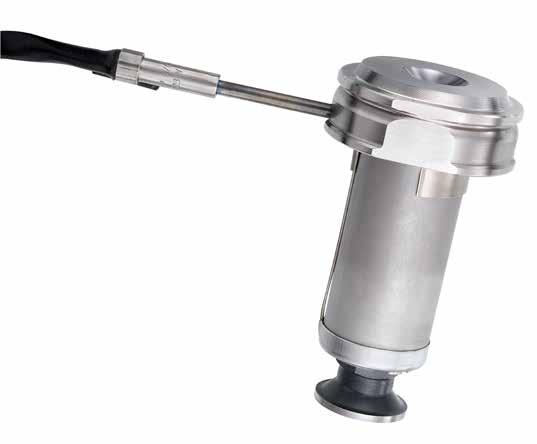
BX25187 50 SL C
Prefix/Length Radius Nut Tip Material
Example: BX25237-75-SP-A or BX25337-50-XS-C
Each Hot Sprue Bushing Assembly includes:
• Body, Tip, Nut, Thermocouple and wiring.
• Cables (ECCA-1) are shown on page K-6.
ELECTRICAL COMPONENTS K-8
.118ø Dowel for keying .04ø Gate H-13 Body Hardened H-13 nut
Replaceable tip L 1/2” or 3/4" .315ø Tip (Flow Channel) 1.000ø R 2.000ø .625 .750
Heater design provides even temperature profile Thermocouple positioned outside heater for easy replacement
PREFIX/ LENGTH L WATTS BX25137 1.375 295 BX25187 1.875 350 BX25237 2.375 455 BX25287 2.875 490 BX25337 3.375 505
HOT SPRUE BUSHINGS INSTALLATION
Typical installation instructions:
APPLICATION GUIDELINES
• To ensure optimal performance, design for a minimum .04” gap between the face of the bushing nut and “B” side of the mold after thermal expansion when gating into a cold runner.
•
•
• “J” type thermocouple
ELECTRICAL COMPONENTS K-9
3.990ø 2.000ø 1.31ø .118ø .218 .625 1.000ø 1.375 Min. L+TE 1.75 Minimum (Connector Clearance) 3.50 Minimum (Lead Clearance) Standard LR523 Locating Ring (Shown on page D-2) Break corner 2.000 1.000 wide x .688 deep channel slot .38 R 1.000 .53 1.06 Wire Channel Insert WC-100 (Sold on page K-7) Recessed Connector ECRC-1 (Sold on page K-6) Standard Nut (-SL) +.002 -.000 +.0006 +.0002 Clearance +.0012 +.0004 PL .91 .100 .218 .625 L+TE +.002 -.000 +.0012 +.0004 .250 (-XS Nut) .04” Minimum .625 L+TE +.002 -.000 +.0012 +.0004 1.250 (-SP Nut)
Nut
3.990ø 2.000ø 1.31ø .118ø 1.000ø 1.375 Min. L+TE 1.75 Minimum (Connector Clearance) 3.50 Minimum (Lead Clearance) Standard LR523 Locating Ring (Shown on page D-2) Break corner 2.000 1.000 wide x .688 deep channel slot .38 R 1.000 .53 1.06 Wire Channel Insert WC-100 (Sold on page K-7) Recessed Connector ECRC-1 (Sold on page K-6) Standard Nut (-SL) +.0006 +.0002 Clearance +.0012 +.0004 PL .91 .100 L+TE +.0012 +.0004 .250 (-XS Nut) .04” Minimum .625 L+TE +.002 -.000 +.0012 +.0004 1.250 (-SP Nut)
Longer
Installation Instructions:
3.990ø 2.000ø 1.31ø .118ø .218 .625 1.000ø 1.375 Min. L+TE 1.75 Minimum (Connector Clearance) 3.50 Minimum (Lead Clearance) Standard LR523 Locating Ring (Shown on page D-2) Break corner 2.000 1.000 wide x .688 deep channel slot .38 R 1.000 .53 1.06 Wire Channel Insert WC-100 (Sold on page K-7) Recessed Connector ECRC-1 (Sold on page K-6) Standard Nut (-SL) +.002 -.000 +.0006 +.0002 Clearance +.0012 +.0004 PL .91 .100 .218 .625 L+TE +.002 -.000 +.0012 +.0004 .250 (-XS Nut) .04” Minimum .625 L+TE +.002 -.000 +.0012 +.0004 1.250 (-SP Nut) CAD insertion point
(Processing Temp °F - Mold Temp °F)
L
Expansion formula (TE): .000007 x
x
230 volt–15 amps
ONLINE RESOURCES
When considering design options, numerous animations can be viewed at procomps.com/animations
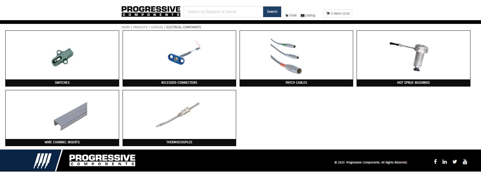
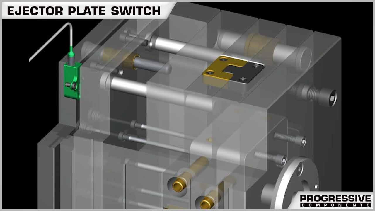
CAD geometry is available online as individual downloads or as part of the CADalog system. The seven formats include: IGES (.igs), ACIS (.sat), STEP (.step), Parasolid (.x_t), SolidWorks (.sldasm), NX (.prt) (Re-Use and MoldWizard) and Visi (.wkf).
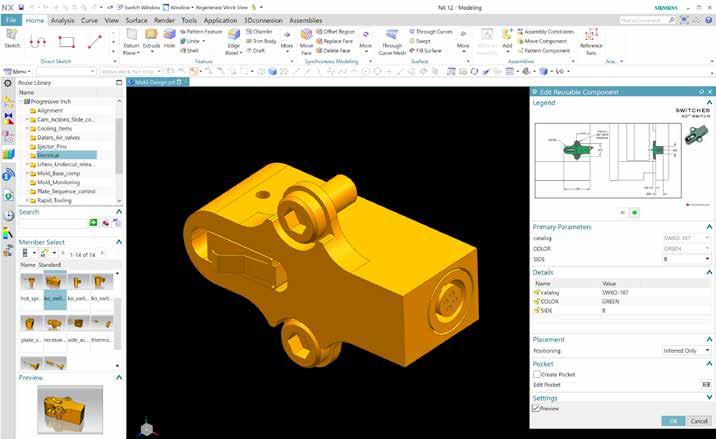
Industry-leading web store expedites the purchasing process. Go to shop.procomps.com for information and additional resources.
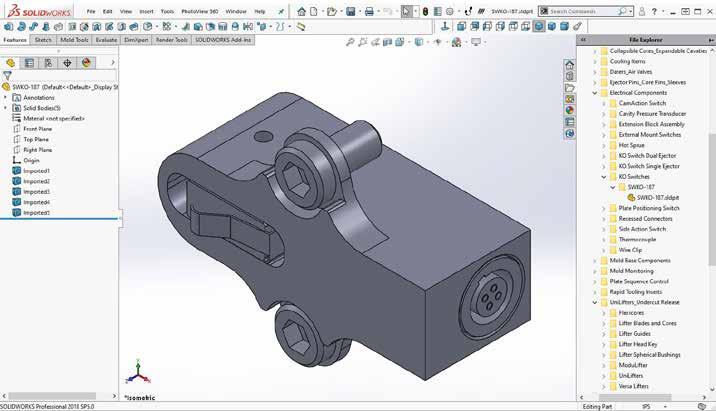
ELECTRICAL COMPONENTS K-10
RAPID TOOLING INSERTS
SECTION L
Rapid Tooling Inserts
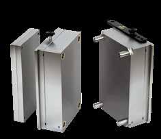
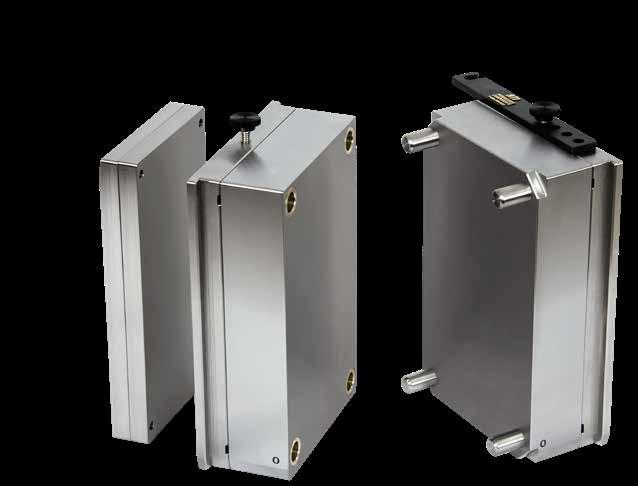
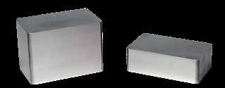
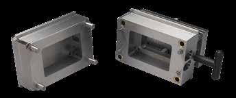
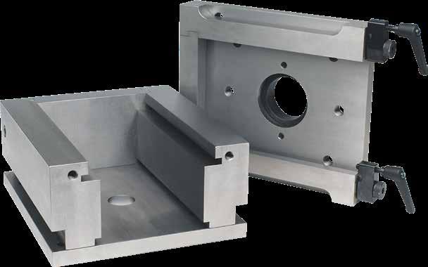
Prefix: RTS, RTL, RTT
Page: L-1
RTI: Complete Cavity & Core Inserts Frames
Prefix: RTLP
Page: L-14
Prefix: RCI, RCIA
Page: L-15
Pins & Bushings Frame Sprue Bushing Support Pillars
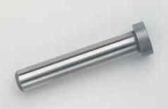
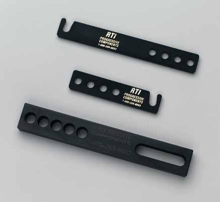
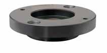
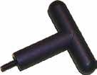
Prefix: RLP, RSB. RGEB
Page: L-20
Prefix: RFS
Page: L-21
Frame Clamp
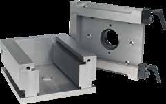
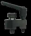
Prefix: RFC
Page: L-22
Prefix: RSP
Page: L-21
Prefix: RTF
T-Handle
Prefix: T
Page: L-22
Thicker Pin Plates
RAPID TOOLING INSERTS ®
Mold Strap provided to prevent unintentional opening
Default locations for assembly
screws
Zero corners are engraved on all plates.
Non-galling Bushings are standard Improved alignment with larger Leader Pins
ALTERNATIVE CONFIGURATIONS AVAILABLE
Guide Pins and Bushings: Rapid Tooling Inserts can include Guide Pins and Bushings and Return Pins at standard Progressive locations or modified to suit your application. See individual pages for more details.
Lead-in provided to ease installation
Sleeve Ejector Plate Systems:
Available as an option on all Rapid Tooling Inserts, Sleeve Ejector Plates allow mold makers to install standard or Thin-Wall Sleeves. See individual pages for more details.
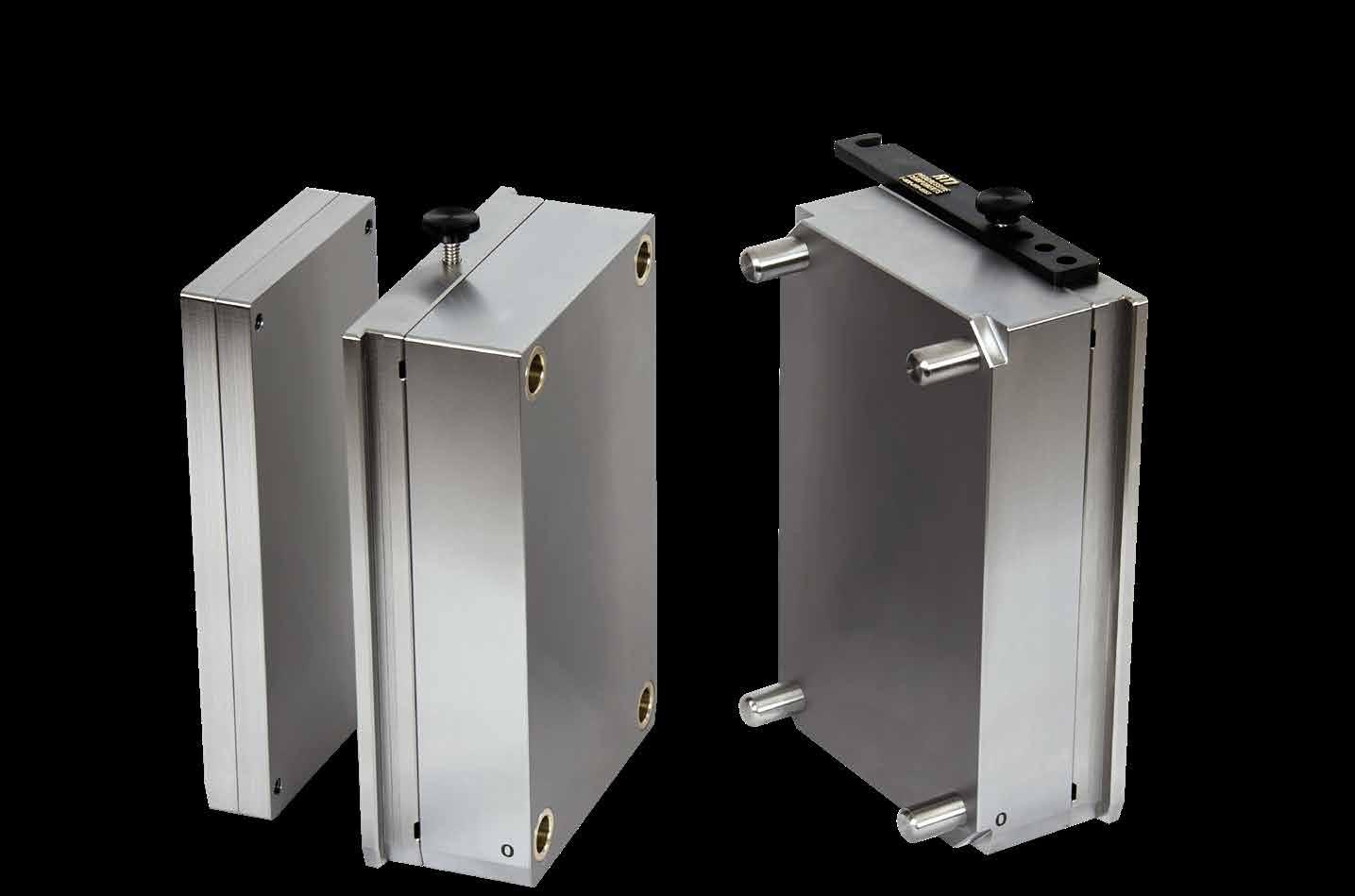
RAPID TOOLING INSERTS L-1
RTI ® 08/09 SERIES
The following inserts are used with frame 08/09:
• 5 x 8 Solid
• 5 x 8 Laminated
• 7.85 x 9 T-Style
5 X 8 SOLID
To Order:
Specify the catalog number at right. Includes Leader Pins, Bushings, all screws, and mold strap/thumb screws.
ALTERNATIVE CONFIGURATIONS AVAILABLE
• With Sleeve Ejector Plates and all components and the extra plate, specify the catalog number at right with “-SEP” as the suffix. Ex. RTS0809-1313-SEP.
• With Guide Pins and Bushings (2) and Return Pins (4) machined and included, specify the catalog number at right with “-RPGPB” as the suffix. Refer to page L-13 for the default pin locations. Ex. RTS0809-1313-RPGPB.
M All plates are P-20 Pre-Hard
L-2
0 2.728 4.000 3.375 3.500 (2) 3.563 (2) .000 3.500 (3) 4.000 3.500 (3) .000 3.375 2.498 2.000 (4) .000 1.750 (4) 2.498 2.728 3.87 7.87 .40 .40 1/4-20 x 3/8" .25 (4) .500 .500 2.000 (4) .000 .50 x 45 .500ø Spirolox RTISPLX-75 Spirolox RTISPLX-86 .760ø .350 .288 .863ø 1/4-20 x 5/8" .246 .246 .230 4.00 .751ø 8.000 .37 x 15 4.996 5.456 0 +.002 –.000 A +.002 –.000 B
RAPID TOOLING INSERTS
9.00 8.00 7.85 5.000 .750
CATALOG NUMBER A B RTS0809-1313 1.376 1.376 RTS0809-1318 1.376 1.876 RTS0809-1818 1.876 1.876 RTS0809-1823 1.876 2.376 RTS0809-2323 2.376 2.376
CAD insertion point
To Order:
Specify the catalog number at right. Includes Leader Pins, Bushings, all screws, and mold strap/thumb screws.
ALTERNATIVE CONFIGURATIONS AVAILABLE
• With Sleeve Ejector Plates and all components and the extra plate, specify the catalog number at right with “-SEP” as the suffix. Ex. RTL0809-1818-SEP.
• With Guide Pins and Bushings (2) and Return Pins (4) machined and included, specify the catalog number at right with “-RPGPB” as the suffix. Refer to page L-13 for the default locations. Ex. RTL0809-1818-RPGPB.
• Stainless Steel: To order the stainless steel assembly, specify the item code in the chart at right. This assembly includes Guide Pins, Bushings, and Return Pins standard.
RTI ® 08/09 SERIES 5 X 8 LAMINATED
M All plates are P-20 Pre-Hard
M All plates are 420 Stainless Steel
RAPID TOOLING INSERTS L-3
0 2.728 2.498 2.000 (8) .000 1.750 (4) 2.498 2.728 3.500 (2 ) 3.563 (2 ) 4.000 3.375 .000 3.500 (3) 4.000 .500ø .760ø .252 .751ø .188 Vents (4) .863ø 4.00 .750 .246ø .230 #10-32 SHCS .750 B2 A2 1/4-20 x 5/8" Vents (4) 3.87 7.87 .500 .500 .40 .40 .25 (4) 1/4-20 x 3/8" Tubular Dowels (2) .50 x 45 .37 x 15 2.000 (4) .000 3.500 (3) 2.125 (4) .000 3.375 0 8.000 4.996 5.456 +.002 –.000 A +.002 –.000 B CATALOG NUMBER A A2 B B2 RTL0809-1818 1.876 1.126 1.876 1.126 RTL0809-1823 1.876 1.126 2.376 1.626 RTL0809-2323 2.376 1.626 2.376 1.626
point
CAD insertion
CATALOG NUMBER A A2 B B2 RTL08092323-RPGPB-SS 2.376 1.626 2.376 1.626
RTI ® 08/09 SERIES
7.85 X 9 T-STYLE
Note: Offset zero location.
To Order:
Specify the catalog number at right. Includes Leader Pins, Bushings, all Screws, and MS65 Mold Strap and Screws.
ALTERNATIVE CONFIGURATIONS AVAILABLE
• With Sleeve Ejector Plates and all components and the extra plate, specify the catalog number at right with “-SEP” as the suffix. Ex. RTT0809-1717-SEP.
• With Guide Pins and Bushings (2) and Return Pins (4) machined and included, specify the catalog number at right with “-RPGPB” as the suffix. Refer to page L-13 for the default locations. Ex. RTT0809-1717-RPGPB.
• Stainless Steel: To order the stainless steel assembly, specify the item code in the chart at right. This assembly includes Guide Pins, Bushings, and Return Pins standard.
**RTT0809-2222 & -2626 have 1/4-20 SHCS
M All plates are P-20 Pre-Hard
M All plates are 420 Stainless Steel
L-4
RAPID TOOLING INSERTS
0 3.925 3.375 (4) 2.728 2.498 2.000 (4) .000 1.750 (4) 2.498 2.728 3.925 4.500 3.500 (2) 5.000 4.375 3.500 (2) .000 3.563 (2) 4.000 3.500 (4) 3.500 (2) 4.000 4.375 9.000 5.000 0 3.375(4) 2.000 (4) 7.850 .000 .000 4.500 .50 x 45º 5.456 4.996 3.87 7.87 .500 .500 .37 .37 .25 (4) 3/8-16 x 5/8" Spirolox RTISPLX-75 Spirolox RTISPLX-86 .350 .751ø .288 .863ø 1/4-20 x 5/8" B2 A2 .246 .750 .750 .246 .230 .500ø .760ø #10-32 SHCS** 4.00 Tubular Dowels (2) Tubular Dowels (2) +.002 –.000 A +.002 –.000 B
CATALOG NUMBER A A2 B B2 RTT0809-1717 1.751 1.001 1.751 1.001 RTT0809-2222 2.251 1.501 2.251 1.501 RTT0809-2626 2.626 1.876 2.626 1.876
CAD insertion point
CATALOG NUMBER A A2 B B2 RTT08092222-RPGPB-SS 2.251 1.501 2.251 1.501
RTI ® 08/10 SERIES
The following inserts are used with frame 08/10:
• 5 x 9 Solid
• 5 x 9 Laminated
• 7.85 x 9 T-Style
To Order:
Specify the catalog number at right. Includes Leader Pins, Bushings, all screws, and mold strap/thumb screws.
ALTERNATIVE CONFIGURATIONS AVAILABLE
• With Sleeve Ejector Plates and all components and the extra plate, specify the catalog number at right with “-SEP” as the suffix. Ex. RTS0810-1818-SEP.
• With Guide Pins and Bushings (2) and Return Pins (4) machined and included, specify the catalog number at right with “-RPGPB” as the suffix. Refer to page L-13 for the default locations. Ex. RTS0810-1818-RPGPB.
M All plates are P-20 Pre-Hard
RAPID TOOLING INSERTS L-5
10.00 9.00 7.85 5.000 .750 0 2.728 2.498 2.000 (4) 1/4-20 x 3/8" .000 1.750 (4) 2.498 2.728 4.37 8.87 .500 .500 .40 .500ø .760ø .751ø .288 .863ø Spirolox RTISPLX-86 .350 4.00 .40 .25 (4) 1/4-20 x 5/8" .246 .246 Spirolox RTISPLX-75 .230 4.000 (2 ) 4.063 (2 ) 2.000 (4) .000 .50 x 45 .37 x 15 4.500 3.875 .000 4.000 (3 ) 4.500 4.000 (3 ) .000 3.875 9.000 4.996 5.456 0 +.002 –.000 A +.002 –.000 B 5 X 9 SOLID CATALOG NUMBER A B RTS0810-1818 1.876 1.876 RTS0810-2323 2.376 2.376
CAD insertion point
RAPID TOOLING INSERTS
RTI ® 08/10 SERIES
To Order:
Specify the catalog number at right. Includes Leader Pins, Bushings, all screws, and mold strap/thumb screws.
ALTERNATIVE CONFIGURATIONS AVAILABLE
• With Sleeve Ejector Plates and all components and the extra plate, specify the catalog number at right with “-SEP” as the suffix. Ex. RTL0810-1818-SEP.
• With Guide Pins and Bushings (2) and Return Pins (4) machined and included, specify the catalog number at right with “-RPGPB” as the suffix. Refer to page L-13 for the default locations. Ex. RTL0810-1818-RPGPB.
M All plates are P-20 Pre-Hard
L-6
0 2.728 2.498 2.000 (8) .000 1.750 (4) 2.498 2.728 3/8-16 x 5/8" #10-32 SHCS 1/4-20 x5/8" .500ø .760ø .252 .751ø .188 .246 .230 .863ø Vents (4) Vents (4) 4.37 4.00 .750 B2 A2 .750 .25 (4) .500 .37 .37 8.87 4.000 (2) Tubular Dowels (2) 4.063 (2) .50 x 45 .37 x 15 Tubular Dowels (2) 4.500 3.875 2.625 (4) .000 4.000 (3) 4.000 (3) 2.625 (4) .000 .3875 4.500 2.000 (8) .000 9.000 4.996 5.456 0 .500 +.002 –.000 A +.002 –.000 B CATALOG NUMBER A A2 B B2 RTL0810-1818 1.876 1.126 1.876 1.126 RTL0810-2323 2.376 1.626 2.376 1.626
5 X 9 LAMINATED
CAD insertion point
To Order:
Specify the catalog number at right. Includes Leader Pins, Bushings, all Screws, and MS65 Mold Strap and Screws.
ALTERNATIVE CONFIGURATIONS AVAILABLE
• With Sleeve Ejector Plates and all components and the extra plate, specify the catalog number at right with “-SEP” as the suffix. Ex. RTT0810-2626-SEP.
• With Guide Pins and Bushings (2) and Return Pins (4) machined and included, specify the catalog number at right with “-RPGPB” as the suffix. Refer to page L-13 for the default locations. Ex. RTT0810-2626-RPGPB.
RTI ® 08/10 SERIES 7.85 X 9 T-STYLE
M All plates are P-20 Pre-Hard
RAPID TOOLING INSERTS L-7
0 0 3.375 2.728 2.498 2.000 (4) .000 1.750 (4) 2.498 2.728 3.925 4.000 (2 ) 4.000 (2 ) 3.925 Tubular Dowels (2) .50 x 45 4.996 5.456 Tubular Dowels (2) .000 4.000 (3 ) LP & SHC S 3.375 (4) 2.000 (4) .000 7.850 4.500 9.000 4.500 3.875 .000 4.063 (2 ) 4.500 4.000 (4 ) LP & SHC S 3.875 3/8-16 x 5/8" 4.37 8.87 .500 .500 .37 .37 .25 (4) Spirolox RTISPLX-75 Spirolox RTISPLX-86 .500ø .350 .751ø .288 .863ø #1/4-20 SHCS 4.00 .750 A2 B2 .750 .760ø 1/4-20 x 5/8" .246 .246 .230 +.002 –.000 A +.002 –.000 B CATALOG NUMBER A A2 B B2 RTT0810-2626 2.626 1.876 2.626 1.876 CAD insertion point
RTI ® 84/90 SERIES
The following inserts are used with frame 84/90:
• 6.5 x 8 Solid
• 6.5 x 8 Laminated
• 8.4 x 9 T-Style
To Order:
Specify the catalog number at right. Includes Leader Pins, Bushings, all screws, and mold strap/thumb screws.
ALTERNATIVE CONFIGURATIONS AVAILABLE
• With Sleeve Ejector Plates and all components and the extra plate, specify the catalog number at right with “-SEP” as the suffix. Ex. RTS8490-1818-SEP.
• With Guide Pins and Bushings (2) and Return Pins (4) machined and included, specify the catalog number at right with “-RPGPB” as the suffix. Refer to page L-13 for the default locations. Ex. RTS8490-1818-RPGPB.
M All plates are P-20 Pre-Hard
L-8
RAPID TOOLING INSERTS
9.000 8.000 8.40 6.500 .750 3.478 4.000 3.250 3.248 2.625 (4) .000 2.375 (4) 3.248 3.478 .000 4.000 3.375 (3 ) .000 3.250 8.000 2.625 (4) .000 .50 x 45 .37 x 15 6.496 6.956 3.500 (2 ) 3.375 (3 ) 3.625 (2 ) 1/4-20 x 3/8" 3.87 7.87 .500 .500 .40 .40 .625ø .875ø .875ø .288 1.109ø 1/4-20 x 5/8" .350 5.50 246 246 .230 .25 (4) Spirolox RTISPLX-87 Spirolox RTISPLX-112 0 0 +.002 –.000 A +.002 –.000 B 6.5
CATALOG NUMBER A B RTS8490-1818 1.876 1.876 RTS8490-2323 2.376 2.376 CAD insertion point
X 8 SOLID
To Order:
Specify the catalog number at right. Includes Leader Pins, Bushings, all screws, and mold strap/thumb screws.
ALTERNATIVE CONFIGURATIONS AVAILABLE
• With Sleeve Ejector Plates and all components and the extra plate, specify the catalog number at right with “-SEP” as the suffix. Ex. RTL8490-1818-SEP.
• With Guide Pins and Bushings (2) and Return Pins (4) machined and included, specify the catalog number at right with “-RPGPB” as the suffix. Refer to page L-13 for the default locations. Ex. RTL8490-1818-RPGPB.
RTI ® 84/90 SERIES 6.5 X 8 LAMINATED
M All plates are P-20 Pre-Hard
RAPID TOOLING INSERTS L-9
0 3.478 3.248 2.625 (8) .000 2.375 (4) 3.248 3.478 3.500 (2) 3.375 (3) Tubular Dowels (2) 1/4-20 x 3/8" 1/4-20 x 5/8" 1/4-20 SHCS .246 .230 3.87 7.87 .500 .500 .40 .40 .625ø .875ø .250 .875ø 1.109ø 5.50 1.000 1.000 A2 B2 .188 Vents (4) Vents (4) .25 (4) 4.000 1.875 (4) .000 3.625 (2) 4.000 3.375 (3) 1.875 (4) .000 3.250 8.000 2.625 (8) .000 6.496 6.956 .50 x 45 .37 x 15 Tubular Dowels (2) 0 +.002 –.000 A +.002 –.000 B CATALOG NUMBER A A2 B B2 RTL8490-1818 1.876 .876 1.876 .876 RTL8490-2323 2.376 1.376 2.376 1.376 CAD insertion point
RTI ® 84/90 SERIES
8.4 X 9 T-STYLE
Note: Offset zero location.
To Order:
Specify the catalog number at right. Includes Leader Pins, Bushings, Screws, and MS65 Mold Strap and Screws.
ALTERNATIVE CONFIGURATIONS AVAILABLE
• With Sleeve Ejector Plates and all components and the extra plate, specify the catalog number at right with “-SEP” as the suffix. Ex. RTT8490-2020-SEP.
• With Guide Pins and Bushings (2) and Return Pins (4) machined and included, specify the catalog number at right with “-RPGPB” as the suffix. Refer to page L-13 for the default locations. Ex. RTT8490-2020-RPGPB.
M All plates are P-20 Pre-Hard
RAPID TOOLING INSERTS L-10
0 4.200 3.575 (4) 3.478 3.248 2.375 (4) .000 2.625 (4) 3.248 3.478 4.200 4.375 3.375 (2 ) 3.625 (2 ) 5.000 4.250 3.500 (4 ) .000 3.500 (2) 4.000 3.500 (2 ) 3.375 (2 ) 3.500 (2 ) 4.000 4.250 0 9.000 5.000 6.496 6.956 8.400 Tubular Dowels (2) Tubular Dowels (2) .50 x 45° .000 4.375 3.575 (4) 2.625 (4) .000 3/8-16 x 5/8" 3.87 .500 .500 .37 .37 .25 (4) 7.87 Spirolox RTISPLX-87 Spirolox RTISPLX-112 .350 .875 1.109ø .625ø .875ø .288 5.500 .750 .246 .230 A2 B2 .750 1/4-20 5/8" 1/4-20 SHCS +.002 –.000 A +.002 –.000 B
CATALOG NUMBER A A2 B B2 RTT8490-2020 2.001 1.251 2.001 1.251 RTT8490-2222 2.251 1.501 2.251 1.501 RTT8490-2626 2.626 1.876 2.626 1.876 CAD insertion point
RTI ® 10/14 SERIES
The following inserts are used with frame 10/14:
7 x 12.9 Solid
To Order: Specify the catalog number at right. Includes Leader Pins, Bushings, all screws, and MS65 Mold Strap and Screws.
ALTERNATIVE CONFIGURATIONS AVAILABLE
• With Sleeve Ejector Plates and all components and the extra plate, specify the catalog number at right with “-SEP” as the suffix.
Ex. RTS1014-2323-SEP.
• With Guide Pins and Bushings (2) and Return Pins (4) machined and included, specify the catalog number at right with “-RPGPB” as the suffix. Refer to page L-13 for the default locations.
Ex. RTS1014-2323-RPGPB.
M All plates are
RAPID TOOLING INSERTS L-11
•
•
14.00 9.87 3.50 3.00 7.000 1.000 12.874 .56 R 0 3.858 3.498 2.875 (4) .000 2.625 (4) 3.498 3.858 5.938 (2 ) 6.062 (2 ) 6.437 5.687 .000 5.812 (3 ) 6.437 5.812 (3 ) .000 5.687 0 12.874 6.996 2.875 (4) .000 7.716 .50 x 45 .37 x 15 3/8-16 x 5/8" .625ø .875ø .360 .875ø 1.109ø Spirolox RTISPLX-112 Spirolox RTISPLX-87 1/4-20 x 5/8" .350 .288 .494 .494 6.00 .25 (4) 6.31 .500 .500 .37 .37 12.75 +.002 –.000 A +.002 –.000 B 7 X 12.9 SOLID CATALOG NUMBER A B RTS1014-2323 2.376 2.376 RTS1014-2828 2.876 2.876 CAD insertion point
7 x 12.9 Laminated
P-20 Pre-Hard
RTI ® 10/14 SERIES
7 X 12.9 LAMINATED
To Order:
Specify the catalog number at right. Includes Leader Pins, Bushings, all screws, and MS65 Mold Strap and Screws.
ALTERNATIVE CONFIGURATIONS AVAILABLE
• With Sleeve Ejector Plates and all components and the extra plate, specify the catalog number at right with “-SEP” as the suffix. Ex. RTL1014-2323-SEP.
• With Guide Pins and Bushings (2) and Return Pins (4) machined and included, specify the catalog number at right with “-RPGPB” as the suffix. Refer to page L-13 for the default locations. Ex. RTL1014-2323-RPGPB.
M All plates are P-20 Pre-Hard
L-12
RAPID TOOLING INSERTS
CATALOG NUMBER A A2 B B2 RTL1014-2323 2.376 1.376 2.376 1.376 RTL1014-2828 2.876 1.876 2.876 1.876 0 3.858 3.498 2.875 (4) .000 2.625 (4) 3.498 3.858 5.938 (2) 6.062 (2) 6.437 5.687 4.312 (4) .000 5.812 (3) 6.437 5.812 (3) 4.312 (4) .000 5.687 12.874 6.996 7.716 .37 x 15 .50 x 45 Tubular Dowels (2) Tubular Dowels (2) 2.875 (8) .000 6.31 12.75 .500 6.00 3/8-16 x 5/8" .25 (4) .500 .37 .37 .625ø .875ø .250 .875ø .288 1.109ø Vents (4) Vents (4) 1/4-20 x 5/8" 1.000 .494 1.000 A2 B2 .360 1/4-20 SHCS 0 +.002 –.000 A +.002 –.000 B CAD insertion point
RTIs are available with optional component configurations in the standard locations shown here.
RAPID TOOLING INSERTS ADDITIONAL COMPONENT OPTIONS
To Order: Specify the catalog number from the previous pages and add the appropriate suffix as shown:
• RPGPB = Return Pins (4), Guide Pins and Bushings (2) machined and included.
• SEP = Sleeve Ejector Plate option
Return Pins, Guide Pins/Bushings are in the same locations for all sizes of Solid (shown), Laminated, and T-Style Inserts. Components may be relocated and other items machined. Contact tech@procomps.com for a quotation.
The Sleeve Ejector Plate (-SEP) option includes the following:
• Extra plate
• Guide Pins & Bushings (2)
• Return Pins (4)
RAPID TOOLING INSERTS L-13
0 2.728 4.000 3.375 Guide Pin 3.000 Guide Pin 3.563 (2) Return Pins 3.500 (2) Return Pins .000 4.000 1.219 (4) .000 2.728 .338 .50ø x 2.5 .375ø x 6 2.625 .251 .64ø .81ø .218 .93ø .751ø 3/8-16 x 5/8 .203 0 2.728 4.500 3.875 Guide Pin 3.750 Guide Pin 4.063 (2) Return Pins 4.000 (2) Return Pins .000 4.500 1.219 (4) .000 2.728 08/09 Size 08/10 Size 84/90 Size 10/14 Size 0 3.478 4.000 3.375 Guide Pin 3.250 Guide Pin 3.625 (2) Return Pins 3.500 (2) Return Pins .000 4.000 1.750 (4) .000 3.478 .338 .50ø x 2.5 .375ø x 6 2.625 .251 .64ø .81ø .218 .93ø .751ø 3/8-16 x 5/8 .203 0 3.858 6.437 5.750 Guide Pin 5.500 Guide Pin 6.000 (2) Return Pins 5.938 (2) Return Pins .000 6.437 2.000 (4) .000 3.858 0 2.728 4.500 3.875 Guide Pin 3.750 Guide Pin 4.063 (2) Return Pins 4.000 (2) Return Pins .000 4.500 1.219 (4) .000 2.728 .338 .50ø x 2.5 .375ø x 6 2.625 .251 .64ø .81ø .218 .93ø .751ø 3/8-16 x 5/8 .203 .500 .187 .812
Rapid Tooling Inserts are available with pre-machined pockets for core and cavity inserts. Also, the pin plate area is pocketed for complete quick tooling changes.
Size: 08/09 Series, 5x8 Laminated unit. Full specs are shown on page L-3. Cavity, core, and pin plate inserts are available on page L-15.
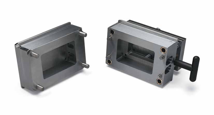
L-14
RAPID TOOLING INSERTS
RTI COMPLETE
4.500 (4) 2.00 4.00 2.625 2.500 (4) 3.0000 5.0000 Clearance pocket in ear plate Insert Pocket Insert Pocket 5.000 .500 (4) .875 (4) .500 (4) .625 (4) 1.125 (TYP) .750 .750 Pin Plate Insert Pocket RSP75L2.6 (2) Support Pillars (Included) C'bore for 1/4-20 SHCS (4 in Ear Plate 4 in Ejector Plate) .250 R (TYP) 3.000 B2 Pin Plate Insert Pocket Clearance pocket +.0000 - .0005 +.0000 - .0005 +.010 - .000 +.010 - .000 0 0 A2+.002 –.000 A +.002 –.000 B CATALOG NUMBER A A2 B B2 RTLP-0809-2323-P 2.376 1.626 2.376 1.626 M A & B Plates: P-20 Pre-Hard, Ear Plates: AISI 4130, Pin Plates: AISI 1018 CAD insertion point
DH2F, Modified H-13 40-42 HRC
This through-hardened material requires no additional heat treatment and is ready for machining of cavity and core details.
QC-10, Aluminum Alloy
155-170 Brinell
This aluminum material has excellent machinability, allowing faster cutting speeds for prototype tools which are not subjected to abrasive plastics.
RAPID TOOLING INSERTS L-15 RTI COMPLETE CORE AND CAVITY INSERTS 4.9985 2.250 (4) T +.005 - 000 +.0000 - 0005 +.0000 - 0005 2.9985 1.250 (4) 1/4-20 Threads (4) .26 R (4) (To fit 1/4" corner radius) .015 Chamfer
PIN PLATE INSERTS CATALOG NUMBER T RCI-0809-16 1.630 RCI-0809-35 3.500 CATALOG NUMBER T RCIA-0809-16 1.630 RCIA-0809-35 3.500 CATALOG NUMBER DESCRIPTION RPI-0809-5 Pin Plate Insert +.000 - 004 2.998 .490 .005 +.000 - 004 4.998 2.250 (4) 1/4" Chamfer .26 R (4) (To fit in 1/4" corner radius) .87ø (2) Support Pillar Clearance 1/4-20 Threads Thru (4) 1.250 (4) M AISI 1018 CAD insertion point 1/4-20 x 7/8” long screws included. 1/4-20 x 7/8” long screws included. 1/4-20 x 5/8” long screws included.
RTI 08/09 FRAME
Accepts:
• 5 x 8 Solid Units, RTS-0809 on Page L-2
• 5 x 8 Laminated Units, RTL-0809 on Page L-3
• 7.85 x 9 T-Style Units, RTT-0809 on Page L-4
M Pre-Hardened Stainless Steel, 32-36 HRC
Includes:
• Frame
• Quick Change Clamps (4)
Frame Sprue Bushings are sold separately on page L-21, Sprue Bushings on page B-1, and Locating Rings on B-2.
To Order:
• To order complete frames, specify catalog number: RTF-0809
• To order an A or B half, contact Customer Service.
RAPID TOOLING INSERTS L-16
9.000 8.000 4.000 5.500 5.000 2.625 7.850 9.000 8.000 4.000 1.126ø 7.850 0 0 3.975 4.120 5.000 5.500
Optional Frame Sprue Bushing
RTI
Accepts:
• 5 x 9 Solid Units, RTS-0810 on Page L-5
• 5 x 9 Laminated Units, RTL-0810 on Page L-6
• 7.85 x 9 T-Style Units, RTT-0810 on Page L-7
M Pre-Hardened Stainless Steel, 32-36 HRC
To Order:
• To order complete frames, specify catalog number: RTF-0810
• To order an A or B half, contact Customer Service.
Frame Sprue Bushings are sold separately on page L-21, Sprue Bushings on page B-1, and Locating Rings on B-2.
RAPID TOOLING INSERTS L-17
Frame
(4) 10.000 9.000 4.500 5.500 5.000 7.850 0 10.000 9.000 4.500 0 7.850 4.120 5.000 5.500 2.625 1.126ø 3.975 Optional Frame
08/10 FRAME Includes: •
• Quick Change Clamps
Sprue Bushing
RTI 84/90 FRAME
Accepts:
• 6.5 x 8 Solid Units, RTS-8490 on Page L-8
• 6.5 x 8 Laminated Units, RTL-8490 on Page L-9
• 8.4 x 9 T-Style Units, RTT-8490 on Page L-10
M Pre-Hardened Stainless Steel, 32-36 HRC
Includes:
• Frame
• Quick Change Clamps (4)
Frame Sprue Bushings are sold separately on page L-21, Sprue Bushings on page B-1, and Locating Rings on B-2.
To Order:
• To order complete frames, specify catalog number: RTF-8490
• To order an A or B half, contact Customer Service.
TOOLING INSERTS L-18
RAPID
7.000 9.000 8.000 4.000 8.400 0 6.500 9.000 8.000 4.000 0 8.400 5.750 6.250 6.500 7.000 2.625 1.126ø 3.975
Optional Frame Sprue Bushing
Accepts:
• 7 x 12.9 Solid Units, RTS-1014 on Page L-11
• 7 x 12.9 Laminated Units, RTL-1014 on Page L-12
RTI 10/14 FRAME
M Pre-Hardened Stainless Steel, 32-36 HRC
Includes:
• Frame
• Quick Change Clamps (4)
Frame Sprue Bushings are sold separately on page L-21, Sprue Bushings on page B-1, and Locating Rings on B-2.
To Order:
• To order complete frames, specify catalog number: RTF-1014
• To order an A or B half, contact Customer Service.
RAPID TOOLING INSERTS L-19
7.000 7.750 13.870 12.874 6.437 0 9.870 13.870 12.874 6.437 9.870 0 7.750 Optional Locating Ring Optional Sprue Bushing 7.000 3.500 1.126ø 5.400 3.25 3.25
Note: The RLP50L1.25 has an “A” dimension of .62”.
SHOULDER BUSHINGS
Note: The “-S” signifies use with Solid inserts.
GUIDE PIN BUSHINGS
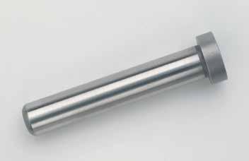
RAPID TOOLING INSERTS L-20 ACCESSORIES LEADER PINS M B L D A T 45 ±3 HRC H D C L T
NOMINAL DIAMETER D +.0000 - .0005 A +.00 - .03 B +.0005 - .0000 M +.00 - .01 T +.000 - .002 1/2 .499 .75 .500 .750 .250 5/8 .624 .87 .625 .865 .250 NOMINAL DIAMETER D +.0008 - .0000 H +.0005 - .0000 C +.000 - .005 T +.000 - .005 1/2 .5000 .7505 .863 .188 5/8 .6250 .8755 1.100 .188 L D=1/2” D=5/8” 1.250 RLP50L1.25 1.750 RLP50L1.75 RLP62L1.75 2.000 RLP50L2.00 2.250 RLP50L2.25 RLP62L2.25 2.500 RLP50L2.50 RLP62L2.50 3.000 RLP50L3.00 RLP62L3.00 3.500 RLP50L3.50 RLP62L3.50 4.000 RLP62L4.00 NOMINAL PLATE THICKNESS L D=1/2” D=5/8” .625 .625 RSB50L.62 .875 .875 RSB62L.87 1.000 .900 RSB50L1.00 1.125 1.125 RSB50L1.12 1.250 1.150 RSB62L1.25 1.375-S 1.275 RSB50L1.27 RSB62L1.27 1.375 1.375 RSB62L1.37 1.500 1.400 RSB50L1.50 RSB62L1.50 1.625 1.625 RSB50L1.62 1.875-S 1.775 RSB50L1.87 RSB62L1.77 1.875 1.875 RSB62L1.87 2.375 2.275 RSB50L2.37 RSB62L2.37 2.875 2.775 RSB62L2.87 CATALOG NUMBER DESCRIPTION RGEB50 1/2” ID Guided Ejector Bushing .7505 .5000 .920 .218 .490 +.0005 -. 0000 +.0008 -. 0000 +.000 -. 005 +.000 -. 005 +.00 -. 01
M AISI 1117 CAD insertion point
M CA954 Solid Bronze
M CA954 Solid Bronze
CAD insertion point CAD insertion point
RTI ACCESSORIES FRAME SPRUE BUSHINGS
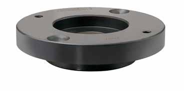
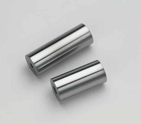
RAPID TOOLING INSERTS L-21
.187 .314 3.990 O R 2.000 2.500 3.312 B.C 1/4-20 FHCS Standard RTI Frame .005 grind stock provided for final fitting Frame Sprue Bushing 50 ± 2 HRC D L C'Bore for 1/4-20 SHCS D L Thru Hole for 1/4-20 SHCS D L C'Bore for 1/4-20 SHCS D L Thru Hole for 1/4-20 SHCS Counterbored SUPPORT
CATALOG NUMBER O R RFS-512 5/32 1/2 RFS-534 5/32 3/4 RFS-712 7/32 1/2 RFS-734 7/32 3/4 RFS-912 9/32 1/2 RFS-934 9/32 3/4 D CATALOG NUMBER L +.002 +.000 SCREW LENGTH (1/4-20 SHCS) 3/4 RSP75L2.1 2.125 2.25 RSP75L2.6 2.625 2.75 RSP75L3.5 3.500 3.75 1 RSP100L2.1 2.125 2.25 RSP100L2.6 2.625 2.75 RSP100L3.5 3.500 3.75 1-1/4 RSP125L2.1 2.125 2.25 RSP125L2.6 2.625 2.75 RSP125L3.5 3.500 3.75 CATALOG NUMBER D L +.001 +.000 SCREW LENGTH (1/4-20 SHCS) RSP75L1.8 3/4 1.813 2.75 RSP75L2.7 2.688 3.75 M AISI 1117 M AISI 1117 CAD insertion point M H-13 S Melonite (SBN) Screw included. Screw included.
PILLARS
Hole Screws included.
Clearance
M MS35 & MS55: Polycarbonate, MS65: AISI 1018
MS35 & MS55 include 1/4-20 thumb screw. MS65 includes (2) 3/8-16 x 1” long SHCS.
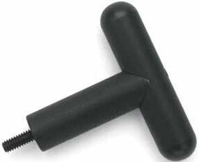
FRAME CLAMPS
T-HANDLES
Frame/Insert Clamp (Sold Individually)

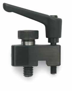
RAPID TOOLING INSERTS L-22
Stripper
orientation
allows tightening by hand 5.50 .275 .50 (Typ) .75 .75 1.0 .50 (Typ) .50 (Typ) 1.875 6.50 .375 .375 .275
RTI ACCESSORIES Notched
Bolt to accept ball detent and maintain
Handle
MS55 MS65 Designed for inserts less than 75 pounds.
CATALOG NUMBER DESCRIPTION RFC-100 RTI
CATALOG NUMBER DESCRIPTION T100 RTI T-Handle
CATALOG NUMBER DESCRIPTION THICKNESS MS35 3.5” Long RTI Strap .200 MS55 5.5” Long RTI Strap .200 MS65 6.5” Long
Duty Strap .500
Heavy
TOOLROOM INNOVATIONS
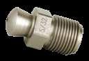


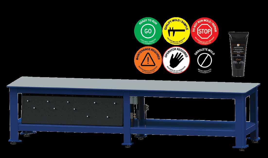
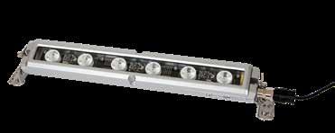
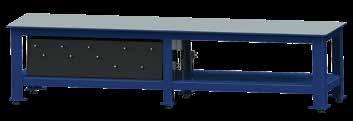
SECTION M
 Rhino Foot™
Rhino Toes
Fin Tip Nozzles
Prefix: RHF Prefix: RHT Prefix: NZFT
Page: M-1
Page: M-1
Page: M-2
Toolroom Bench
Status Tags
Mold Finish Guides
Mold Light Bar Prefix: TRB Prefix: ST Prefix: LIT Prefix: MLB, MLBTF
Page: M-4
Page: M-6
Page: M-7 Page: M-8
Synthetic Grease
Prefix: SYN
Page: M-8
Rhino Foot™
Rhino Toes
Fin Tip Nozzles
Prefix: RHF Prefix: RHT Prefix: NZFT
Page: M-1
Page: M-1
Page: M-2
Toolroom Bench
Status Tags
Mold Finish Guides
Mold Light Bar Prefix: TRB Prefix: ST Prefix: LIT Prefix: MLB, MLBTF
Page: M-4
Page: M-6
Page: M-7 Page: M-8
Synthetic Grease
Prefix: SYN
Page: M-8
Progressive offers the Rhino foot product line to eliminate the hazards associated with placing molds and plates on wood blocks and pallets.
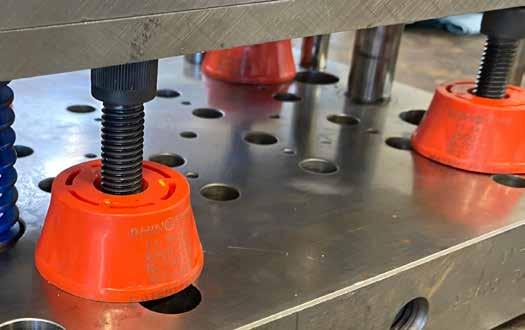

• Safer, cleaner, and improves 5S standards within the shop.
• 7,000 lbs (3,175 kg) safe working load, with a safety factor of 3.
• Height and load is marked for easy identification.
RHINO FOOT ™
Compression With Bolt
Compression On Faces
APPLICATION GUIDELINES
• Rhino Toes are utilized to suppport a plate or hot runner system for bench work or storage.
• Use with a 1/2-13 bolt or threaded rod for additional heights and plate separation.
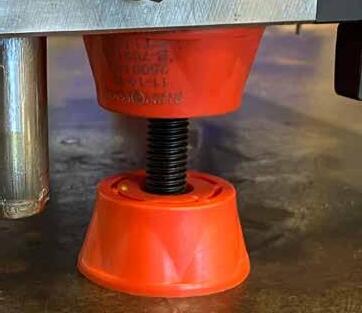
• Toes have a safety factor of 3.
• Mold maker to supply 1/2-13 threaded rod or bolt.
TOOLROOM INNOVATIONS M-1
CATALOG NUMBER INCH CATALOG NUMBER METRIC H SAFE WORKING LOAD (LBS/KG) RHF2 RHF50 2” / 50mm 7,000 / 3,000 RHF3 RHF75 3” / 75mm 7,000 / 3,000 RHF4 RHF100 4” / 100mm 7,000 / 3,000 CATALOG NUMBER H COMPRESSION
SAFE WORKING LOAD (LBS/KG)
SAFE WORKING LOAD (LBS/KG) RHT1 1” 630 / 286 2,500 / 1,000 RHT2 2” 800 / 363 2,500 / 1,000 RHT3 3” 830 / 377 2,500 / 1,000
WITH BOLT
COMPRESSION ON FACES
H H 2.125ø Ø4.125 4.125ø Magnet H H Magnet 1/2-13 Thread 2.125ø Ø2.125 Ø4.125 4.125ø Magnet US Patent No. 11,154,135
RHINO TOES ™
The Fin Tip Nozzles provide the best solution to prevent mold-damaging strings. This patented new design dramatically reduces the solidification time, the root cause of string formation.
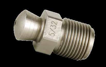

• No need to increase cycle times, use smaller orifice sizes, or nozzle tips with restrictive internal bores in order to stop nozzle stringing.
• Proven successful with commodity and engineering grade materials, both filled and unfilled.
APPLICATION GUIDELINES
• Heat-conducting thermal fins extend 75% into the melt stream, for rapid solidification.
• Reduced tip mass provides faster thermal equilibrium and shorter cycle times.
• Flow area equivalent to Full Flow style tips, for minimal increase in shear and pressure.
• Orifice sizes are slightly smaller than nominal. There is no need to use a 1/32” smaller tip.
• Hardened 420 stainless steel for corrosion resistance and long life.
• Large internal transition radius virtually eliminates “dead spots” where material can stagnate.
• Reduced face diameter increases machine’s nozzle touch force, reduces blowback, and eliminates the need for nozzle insulators.
• The 1/2” nozzle radius is actually 0.496”. Together with the sand blasted surface finish, it ensures a proper seal with the sprue bushing, which prevents material leaks and air infiltration.
• Land lengths vary with the orifice size. The larger the orifice, the longer the land length, for increased thermal conductivity.
• Engraved orifice size helps reduce mold set-up time.
TOOLROOM INNOVATIONS M-2
NOZZLES
F
Blasted Surface Finish Heat Sinking Fins Maximum Orifice Diameter Engraved Orifice Size Reduced Face Diameter & Mass Large Transition Radius Conical Tapered Bore 1/2” R 7/8” Hex 7/8-14 Thread CATALOG NUMBER O NOMINAL O ACTUAL F QTY FINS L NZFT156 5/32 .148 3 1.794 NZFT187 3/16 .178 3 1.817 NZFT219 7/32 .207 4 1.839 NZFT250 1/4 .236 4 1.886 NZFT281 9/32 .265 4 1.881 NZFT312 5/16 .295 4 1.903 NZFT344 11/32 .324 4 1.923 NZFT375 3/8 .353 4 1.943 L O F Sand Blasted Surface Finish Heat Sinking Fins Maximum Orifice Diameter Engraved Orifice Size Reduced Face Diameter & Mass Large Transition Radius Conical Tapered Bore 1/2” R 7/8” Hex 7/8-14 Thread M 420 Stainless Steel H 48-50 HRC U.S. Patent No. 10,821,642
Sand
NOZZLE CADDIE
Progressive offers a caddie to keep the Fin Tip and other machine Nozzles on the press, close to the tools.
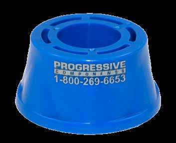
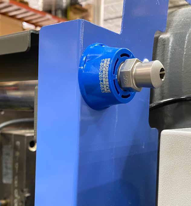
NOZZLE WRENCH
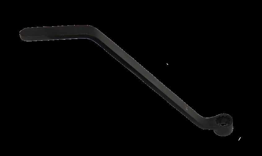
TOOLROOM INNOVATIONS M-3
CATALOG NUMBER DESCRIPTION NZLCAD1 Machine Nozzle Caddie (Blue) Magnet Ø2.1 1.0 Ø.90
M Steel S Zinc Phosphate
TOOLROOM BENCH
Bench Optimized for Mold Assembly/Disassembly:
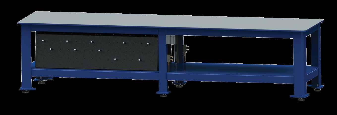
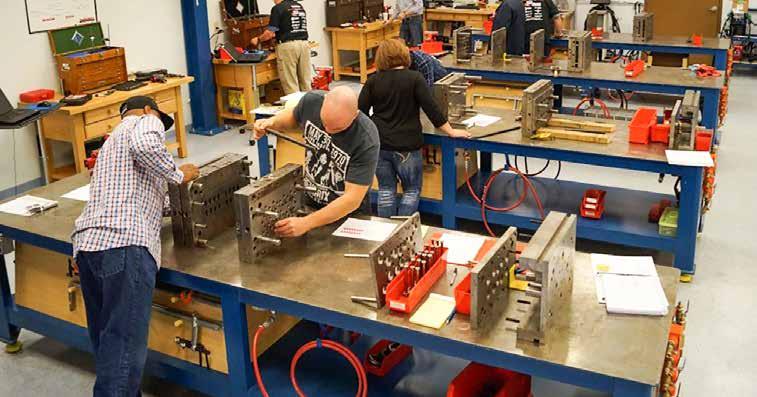
• More efficient mold assembly and disassembly
• Convenient working height
• Shelf for storage
• 3/4” thick Blanchard Ground steel work surface for smooth and easy positioning of mold plates
• Radiused corners on legs to reduce knee injuries
• Bench is all-welded construction
• Max static load rating is 30,000 lbs
Standardized Design:
• Adopt best practices across your facility
• Consistent so all work areas are equal
Tool Storage Option:
• Easy access to tools needed on the bench
• Prevent clutter
• Pre-drilled holes and repositionable aluminum pegs for organized and flexible tool storage
• Tool Storage unit fits under one section of the bench
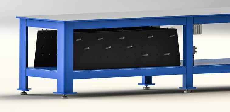
• 1/4˝ steel, black powder coated
• Recessed 2” from shelf edge and angled back to keep tools in place
• Each tool storage unit includes one board on each side of bench
M-4
TOOLROOM INNOVATIONS
34½"
SCALE: 1:1 PAGE:
143"
235 INDUSTRIAL WAUCONDA, PHONE: WWW.PROCOMPS.COM SEE NOTES SEE NOTES
TREATMENT: OTHER:
36"
Ground Steel Surface
Water Manifold and Flow Meter Option:
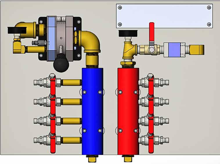
• Manifold and valves allow quick connection for mold water testing
• Flow meter can be used to ensure flow is even and there are no restrictions
• Ability to bench test for leaks saves valuable time versus testing in the press
• Red and blue manifold similar to what is at the press
• Convenient drain feature provides cleaner, more efficient drainage after testing
Air Manifold Option:
• Convenient connection of air tools
• One on each side of the bench
• Hooks to hold air hose
Electrical Option:
• 2 outlets on either side of the bench
• Electrical hookups are routed under the bench to minimize obstructions
• Positioned centrally on bench for easy access TRB34
To Order:
Options:
F = Manifold and Flow Meter
T = Tool Storage
A = Air
E = Electrical
Note: Standard Toolroom Bench dimensions are 3´ wide, by 12´long and 34˝ high.
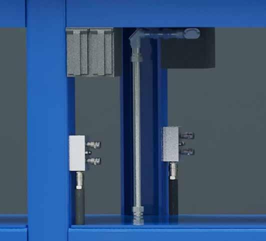
Examples:
TRB34-FTAE = Toolroom Bench with all options installed
TRB34-AE = Toolroom Bench with Air and Electrical options installed
TOOLROOM INNOVATIONS M-5 TOOLROOM BENCH
- F T A E
TOOLROOM INNOVATIONS
STATUS TAGS
APPLICATION GUIDELINES
• Status Tags magnetically attach to molds and are color-coded for easy identification of mold status at a glance.
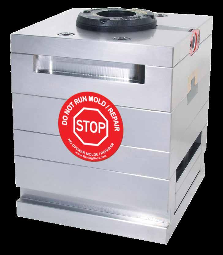
• 3.75” Diameter.
• Magnetic back.
• Laminated vinyl surface.
• Sold in packages of 12 tags.
CATALOG NUMBER
COLOR
DESCRIPTION
ST-GRE Green Ready to Run
ST-YEL Yellow Qualify Mold / Sample
ST-RED Red Do Not Run Mold / Repair
ST-ORN Orange
Maintenance Required
ST-WHT White Operator Required
ST-BLK Black Obsolete Mold
M-6
FEATURES
• Molded, ABS plastic plaque, 8-1/2 x 11, showing typical finishes to aid in communication with customers.
• Includes A-1, A-2, A-3, B-1, B-2, B-3, C-1, C-2, C-3, D-1, and D-3 finishes.
• Provided by the Society of Plastics Industry
LOCATING RING SHIMS
APPLICATION GUIDELINES
• Shims allow for pre-loading the flanged Locating Rings to compensate for a worn or dished platen as well as compensate for high injection pressures in the center of the mold.
• Three thicknesses to enable preload for the center of the mold.
• Sold individually to accommodate stacking requirements.
• Sized with screw clearances for use with flanged Locating Rings sold on page B-3.
TOOLROOM INNOVATIONS M-7 MOLD FINISH GUIDE
LIT-MFC
CATALOG NUMBER
NUMBER THICKNESS LRS-02 .002” LRS-03 .003” LRS-05 .005”
CATALOG
M 316 Stainless Steel
MOLD LIGHT BAR
Mold Light Bars provide illumination at the molding press to reduce eye strain and increase visibility for operators and repair technicians.
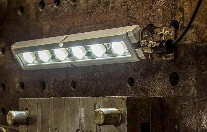
Light Bar Technical Information:
• Wire direct to 24V machine power or optional transformer
• Mounts to press platen magnetically to direct light on mold
• 12w 450mA
Light Bar Product Information:
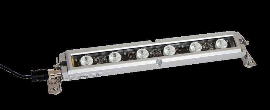
• Six LED floodlights per unit. Rated for 50,000 hours
Aluminum casting with tempered glass is water and shock resistant
45° and 90° swivel mounting brackets included
IP67 Rated
Transformer Information:
Plugs directly into 110v outlet
Two screw wire connection
SYNTHETIC MOLD GREASE
APPLICATION GUIDELINES
• Premium synthetic mold grease provides superior lubrication to sliding or moving components within molds and tooling.

• Engineered for food and medical molding environments
• Low migration
• Should only be applied in a thin layer by hand
• NSF H1 Registered
• Thermally stable to 570°F (300°C)
TOOLROOM
M-8
INNOVATIONS
CATALOG NUMBER DESCRIPTION SYN-100 100g Tube CATALOG NUMBER DESCRIPTION VOLTAGE LENGTH WIDTH MLB2X16 Light Bar 24V 16˝ 2˝ MLBTF Transformer 110V 24V
