HABITAT AS BIOLOGICAL MACHINE


to Master Thesis
I lived the city, the rurality and the pandemic.
I lived inside urban environments most time of my life. Simultaneously I spent quite a lot of time in natural environments. Over weekends I would move to fairly remote, rural landscape. I spent winters and summers knowing and interacting with different regions and natural landscape. This chance became first a form of education and over time, respect and understanding of natural ecosystems, so far consider disconnected from the urban environment.
In the last years I experienced the pandemic. During critical times we have to react and take advantage of crisis and, despite the damages, learn as much as possible from the situation. We learned how fragile our ecosystem is, in the epoch of the Anthropocene and even more so during a global pandemic. Over months we managed to reorganize our method of interacting, making it remote where possible, and reducing neuralgic point of assemblage. Meaning, there is possibil ity of communication, interaction and exchange of knowledge and ideas through means made available by modern technology.
We live in a scenario where adaptation is key to changing conditions endan gering contemporary society. The over pushed urbanization where we currently inhabit and interact results an unstable and unbalanced environment. Answers have to be found in re-designing the established urban infrastructure, and questions have to be asked considering non-anthropocentric criterion, to direct the growth of infrastructure towards the opposite, so-far-adopted direction: a sustain able and non-anthropocentric one.
Human head towards social and technological development, aiming for a better, structured society, in an environment as close as possible to ideal living condition. Following this trend, we end up establishing ecosystems recognizable in the urban landscape. It is in the last decades that we grew aware of how, what we as pire to, our societal thriving, does not take in account the endangerment that each kind of organism belonging to natural ecosystem and landscapes is undergoing.
Natural landscapes all over the world provided for us from day one and every
ecosystem that in centuries took shape in them, lives on a subtle equilibrium that is carefully preserved. The solution is not for human to move out and abandon over-saturated living areas, but to avoid increasing any further the inhabiting pressure that pushes these areas towards non-human dimensions. Once the equilibrium is lost, it cannot be re-balanced simply thriving on the idea of a general regreening of our urban landscape. It is easy and naïve think that that the solution to those problems established in the Urban landscape hides in the regreening of cities: transform a roof into a limited green area with small trees planted around. Sure, design-wise, it might be a partial and concise answer to increase well-being of people inhabiting cities but also the very least impact reducing air pollution. We can consider this method of action a mere cover to those major problematic originating from the Urbansphere, global-connecting mesh that is molding ecosystems of the biosphere.
Architects, designers and engineers bear the responsibility to understand how green technology evolves in an urban framework. We acknowledge the existence of waste, pollution and by-products deriving from urbanization, but we do not perceive them, we cannot perceive them: the amount of urban by-product closer is not perceived as a threat to us. It is hard to render the whole picture.
Today, inside our urban landscape, we consider technically and technological ly advanced a 50-stories building made of concrete, steel and glass. This huge amount of material that from raw state has been manufactured represent, along with the resulting system of construction by-products, the strong forces that are changing the Biosphere and re-shaping the Geosphere. The technical develop ment reached in the construction sector will be soon consistently reinforced and reorganized by robotic fabrication, and eventually we will interconnect with ma chines and use them push urban infrastructure beyond established schematics and outside the border of current living-in-cities definition.
We are not talking just about buildings themselves but about the whole construc tion industry, and with it the global infrastructure that is being created surrounding the planet as a new artificial layer additional to the existing spheres. The Biosphere as manipulating agent is transforming into a geological agent,
molding the landscape via a new layer, the so-called Urbansphere, “the sphere of the systemic infrastructures of support for our urban society, which has a de cisive impact on the evolution of the biosphere and thus on the evolution of the living systems that inhabit it” (C. Pasquero, M. Poletto).
Established that the Urbansphere is “what we may call the global apparatus of contemporary urbanity, a stack of dense informational, material and energetic networks supporting our society’s increasingly demanding metabolism”1. Where and when human interact with each other, an infinite number of interlocking feed back loops will give life to the urban ecosystem. The strategy is not to destroy the self-generating Urbansphere, but to develop and adapt it to a different landscape and ecosystem.
The Noosphere is the sphere of thoughts, and therefore knowledge and infor mation, enveloping the Earth and shaping it: human consciousness and mental activity has consequently direct influence on the biosphere, including its relation to planetary evolution. By the definition of Vladimir Vernadsky, it is the third stage of Earth’s development, after the geosphere (rocks, water, and air) and the bio sphere (all the living things). The word comes from the Greek noos (mind) and sphaira (sphere).
Humanity is now the dominant force of change on planet Earth. This new reality is changing the dynamics of the Earth system. The Noosphere is a geological agent. Earth is rapidly moving away from a stable climate, a rich diversity of species and a resilient biosphere into a new geological epoch referred to as the Anthropocene.
According to Vernadsky, the biosphere became a real geological force that is changing the face of the earth, and the biosphere is changing into the noosphere. When the biosphere is changed into a human-dominant environment it becomes the noosphere. The self-sufficient biosphere is being used by human as a means of resources for himself unmindful of the needs of other organisms. Teilhard de Chardin expands the theory of the Noosphere with the concept of internet as an evolution of thought and consciousness, since such synthetic infrastructure
enables knowledge exchange.
Under such complex condition the Urbansphere can claim the Noosphere as one of its layers, a derivation of the human domain and accordingly let the distinction between natural and non-natural slowly fade out. Human as species in its complexity remain part of the natural realm. Hence, it results faulty to categorized its extension over the biological domain as non-natural. This is the turning point where synthetic systems turn into biological schemes. Human and non-human be comes layers of the same system.
The act of building and fabricating does not exclude humans from nature, cities represent a synthetic procedure, an ecosystem of aggregation belonging to the same sphere of human as living being and biological ecosystems. It is the trans formation of natural landscapes, as not artificially generated, into synthetic land scapes, maintaining nevertheless the biological factor.
If we call city the place we inhabit, then the whole planet could be called a city. This overall comprehensive environment can be finally defined as the Ur bansphere. What does make sense is consider the harming impact of human activity on natural ecosystem as a completely natural and unacceptable conse quence of the Urbansphere we generated.
We don’t consider out of the ordinary a colony of ants that builds a nest using what surrounds them and with the same logic we don’t consider out of the natural spectrum a human aggregation building with more intricate methods the nesting ecosystem that is the city.
The act of building is completely natural, the impact and by-product of how we build and progress is the non-natural action that brings harming consequences in a perfectly balanced biological ecosystem. The large, old artifact we use to construct is what differentiates us and causes strong impact.
A symbiotic relationship has born and grew stronger between urban environment and human domain, as one has no meaning without the other.
We are mutually dependent: the city without inhabitant become merely an inert, inactive mass of converted material, laid out by a logic that works only for us. It remains a neuralgic system deprived of the electric impulse that allows its oper ation.
If human were to abandon the urbanization as it is, carefully designed over time, they would lose the artificial concept of belonging. The concept reveals roots and identifies us through membership of larger community, inhabiting small towns or metropolis. Group identity, aggregation and feeling of belonging to regions and groups is a spontaneous, man-made need, an instinct of aggregation that makes us feel safe. What is the urban system if not a procedure of aggregation?
How could we transform such deeply-rooted conception of the urban infrastruc ture? Changing perspective and expectation from an established environment, generated by procedures of aggregation, we will re-design it through modern techniques that suit better human and environment together. Changing how we look at and render the urban landscape, which denote the way we interact with the Urbansphere, will allows us to tear down those precon ceptions we are grasping on to, and consequently transform radically the concept of human habitat.
Following this presupposition, we have to think broader of what merging nature and urban landscape means and how it could benefit the both spheres. Re-establish the ecosystem of the biosphere does not happen by bringing bits of nature into our urban landscape, but the other way around, by bringing our urban infra structure into the natural landscape. We cannot pretend to infiltrate and corrupt this establishment all over again by reenacting those protocols that let our urban environment grow negligent of the biosphere. For this reason, is our responsibility to re-script living-space protocols and convert them to an alternative, suitable and sustainable way of living.
In the 60s there was 3 billion people in the world. Today, we are 7.5 billion and soon, in 2050, estimates predict that the number will increase to 9 billion. What we have to understand is that demography is the key. Pollution and waste increase with demography, the Energy budget, a pro capita energy consumption and CO2 production average, does not change much over the decades. More people demand more resources.
Favoring the use of certain resources, applied to selected technology or method ology, lead relentlessly to sacrifice of others, e.g., soil in the case of mining and extraction of material and water in the chain of manufacturing processes. This kind of limited resources available on the planet are also those which grant us living and surviving. It is not about choosing a technology over the other, but to choose carefully, taking in consideration resource availability and raising aware ness in resource exploitation. Focusing on one technology and holding back an other one, force human development to undertake one direction, whether right or wrong.
A similar line of reasoning is applied to the construction industry. According to research the construction sector contributes to 23% air pollution, along with cli matic change, drinking water pollution and landfill wastes, all in high percentage. Building material, such as concrete, aluminum and steel are directly responsible for large quantity of CO2 emission due to high embodied energy content. Construction activity consume half of all the resources extracted from nature, and account for one-sixth of global freshwater consumption, and one-quarter of global waste. After water, concrete is the second most-consumed material on the planet and its production is substantially growing, expected to increase from 4.4 bil lion tons, reaching production up to 5.5 billion tons by 2050. Unfortunately, this comes at a huge environmental cost, accounting for almost eight percent of the global carbon emissions. Seen numbers, we can realize how deep is impact of modern construction methodology throughout global landscapes.
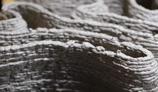
Because of the previously enounced reasons, I decided to conduct my research focusing on construction of alternative habitats using alternative material to ce ment, which could however resemble this last one in the range of structural char acteristics. This choice brought me to clay, which can be considered a more sus tainable material then cement, because its extraction is much easier and more direct. Found in nature in form of powder, it allows to cut a large amount of embodied energy, since it doesn’t need further elaboration after the extraction pro cess and furthermore clay presents similar behavior in terms of tensile and com pressive strength. I have been fascinating from this material and its potential since interesting examples were brought to my attention during my study career, such as the work of Mario Cucinella or the extensive research and work that is being conduct at IAAC in Barcelona. In my work I will make use of clay-based mixtures with different biobased compounds, in order to study the sustainable potential of this material and speculate on the reaction and integration of different mixtures applied to natural landscapes.
Such experimental investigation always fascinated me, and I see a lot potential in the use biological material as construction material. There is still a lot of effort that has to be placed in research, but I find extremely interesting that already during the second half of the 20th century, a movement addressed to crafting and shap ing the natural landscape using only local and biological material was born in answer to the disruptive societal trend that was gaining the upper hand. It was already clear that such increasing trend was negative for the environment and our home the Earth, and to contrast this prevailing trend the Land Art move ment was born, developing concurrently an ecological and environmental con science.
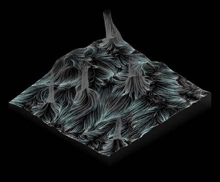
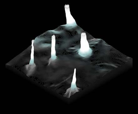
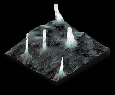
At page 11 is illustrated an introduction to what the Land Art movement is. The sequence of images 1 and 2 show The Lightning Field from Walter de Maria, 1977, He was one of the first and most relevant exponent of the movement. This installation highlights how, by modifing the landscape via a pattern, either pre cisely designed or randomly, consequences in the surrounding nature will hap pen, like in this case, where poles placed in a field act as beacon for lightning during tempests. To each action brought in the landscape, a reaction will follow.
The Lightning Field from Wal ter de Maria,
The Lightning Field from Wal ter de Maria,


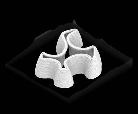
The intent of my work is to re-shape landscapes using robotic fabrication and local biological material to create an extension of a selected landscape. It will be a functional extension designed for all linving being: such machinically pro duced extension embodies a new habitat, explored not only for human, but in the broadeer sense of being, also for th eflora and fauna belonging to a designated environment.
Local materials guarantee the continuity between the landscape and the synthetic extension, which eventually generates a living infrastructure.
Investigations and experimentations with the purpose of creating new spaces immersed and embedded in natural environments had been already conducted over thhe 60s and 70s by artist belonging to the Land Art movement.
Exploring the movement I understood artist aimed to create new spaces that could guarantee innovative ways of interaction for humans with the surrounding natural environment. Careful and calculated use of local resources generated new athmsphere and new pattern in known and yet not populated location. They studied new means and alternative approaches to bring the audience an immersive experience that guarantees a different point of view of otherwise already experienced environments.
The investigation of the Land Art movement brought me to understand why should I ever study a way of re-shaping landscapes artificially using synthetic agents, and what function would this offsetted infrastructure have for human and natural realm.
For the artist it was not just about producing piece of art that can influence the behaviour of human in relation to nature, but also establish a new sense of aware ness for human toward nature, in asociety that was so far remarkably anthropo centric and self-centered.
As a matter of fact, the Land art movement coincided with the popularity of the rejection of urban living and its counterpart, an enthusiasm for that which is rural.
Artists used to see the planet Earth as home to humanity and simultaneously they used to agree with the manifest of the emergent ecological movement.
Museums and galleries were rejected as setting of artistic activity, while artist’s will was to work with nature in nature. The movement influences todays landscape architecture and environmental sculpture.


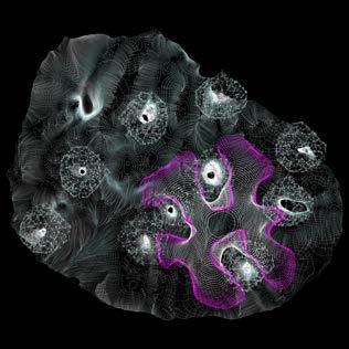
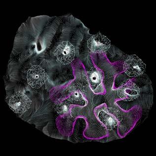
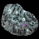
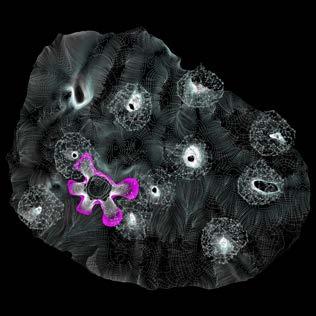
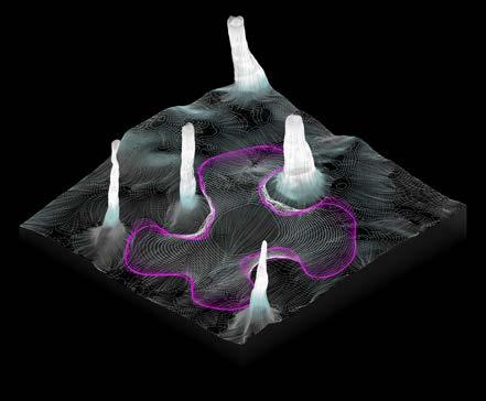
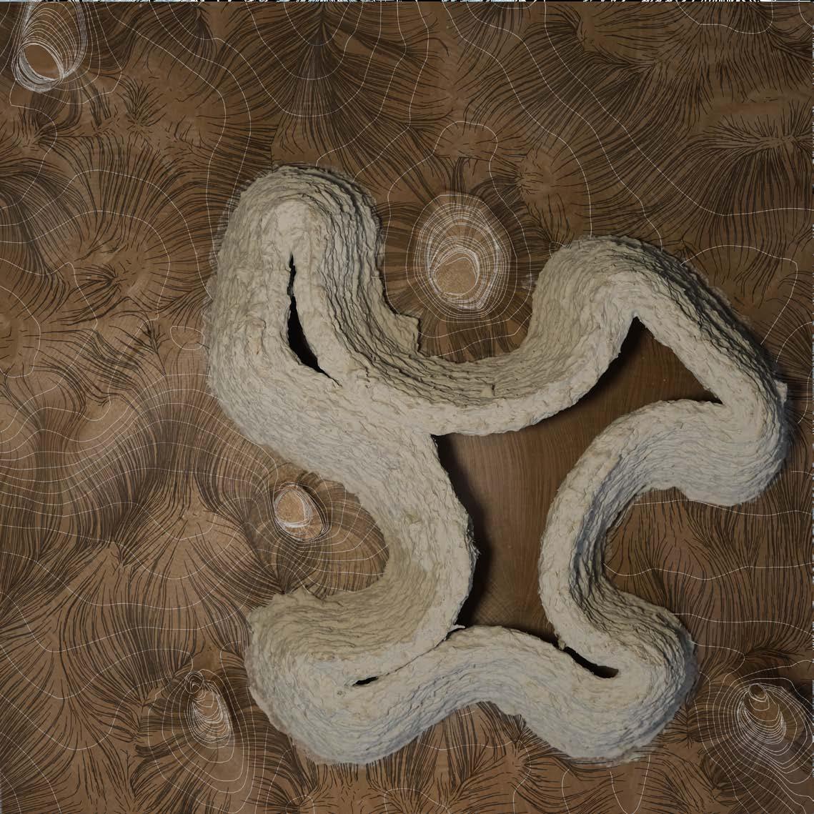
In the images 3 and 4 of page 11 is illustrated Spiral Jetty built by Robert Smithson, American sculptor fundamental to the movement who rethought radi cally landscapes all over the world. This work is a good opening example of what the Land Art movement deals with. Spiral Jetty is built on the northeastern shore of the Great Salt Lake in Utah entirely of mud, salt crystals, and basalt rocks. The artist used only local material, drawing a spiraling path stretching into the lake.
The location choice is never fortuitous, it is built where the tide cover and uncover the shore regularly, so that access is guaranteed to the public only under certain condition. The surrounding landscape changes and with it the sculpture when is submerged. Water offers different pigmentation thanks to the presence of unusual bacteria and algae due to high salinity level. This is a lesson of how considering the natural landscape not as static, but as a self-organized ecosystem changing over time. It does not create interaction and new dynamics only in the human sphere, but also under the domain of acting natural forces: the deposition of rocks gives life to new flows of water, influencing the growth of algae and bacteria on the site.
Beyond the common key point of urban rejection, I share many ideas with artists from the movement. Over my project I notice one fundamental key point where the movement and my work will not meet: I re-produce the concept of new inter active spaces using the previously defined “machine”. The fabrication method in my case will be a sort of evolution of the process developed by the Land Art movement: my idea is to adopt a robotic approach to the on-site production, where artists from the movement, either for choice or not, kept an analogic ap proach to the production methodology as depicted in image number 5, Andy Goldsworthy working on his sculpture.
Furthermore, I adopt digital techniques of designing and producing a complete data-driven shape. The difference lies only in the means used to collect and elaborate data from the natural environment, where for the movement is a shaped inspired by the natural domain and influenced by it.
I analyized the work from Andy Goldsworthy, a British artist active in the move ment starting from the 70s. I focused on his site-specific sculpure work, where he used to produce pattern and sculputere built using only local material collected from the surrounding natural realm, like wood, stones, leaves, clay and snow.

Andy Goldsworthy is a very active and contributive artist of the movement. Along with the work of Robert Smithson I studied many of his works and sculptures, where strong familiarity with my project can as well be found.
Andy Goldsworthy, (born 1956) is a British sculptor, photographer and environ mentalist producing site-specific sculpture and land art situated in natural and urban settings, where expositions used to take place. Goldsworthy often used similar material as illustrated in page 15.
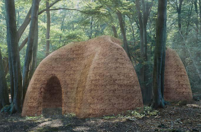
In image 6, Clay Dome in Rio de Janeiro, 2012, Goldsworthy use as primar material clay, same material I choose to focus my study on, while in the pictures number 7, The Oak Room, La Coste Castle, 2009 he produces his work using wood, material that I, as well, embeddied in my project.
I first brought to the attention this two projects because they represnt the idea of how human can conceive the concept of habitat in a primordial and immature way. Goldsworthy was trying to put back in contact the human sphere with the natural sphere, as he used to say that “We often forget that ‘we are nature’. Na ture is not something separate from us. So when we say that we have lost our connection to nature, what we are really saying is we’ve lost our connection to ourselves.”
Such places let us embrace nature as long as we are inside that room, but the artist always pushed to blur the boundaries between his sculptures and natu ral environment. He experimented new patterns that could not only interact with nature, but also let human interact with nature, making of the sculpture a media to approach and create unexperienced dynamics between human and natural landscape. The playground of his art was most of the time the forest, which for my project represent the place where everything that happens is a product of its characteristics.
Since the setting of the forest is important to me, I brought to the attention cases where the artist measure against the forest, for the choice of the material system, the choice of the pattern presented with the sculpture and what impact was Goldsworrthy looking for in such environment.


Storm King Wall in Mountain ville, NY, USA, 2000
Storm King Wall in Mountain ville, NY, USA, 2000


Wood Line in Park Presidio, San Francisco USA, 2010
Wood Line in Park Presidio, San Francisco USA, 2010


10
Images 8 and 9 show the Storm King Wall in Mountainville, NY, USA, 2000.
Andy Goldsworthy built a serpentine dry wall using field stones. Incorporating the remains of a fallen-down farm wall that Goldsworthy discovered on the site, the sculpture crosses over old farm roads, snakes around maple and oak trees, plunges into a pond and then seems to re-remerge on the pond’s opposite bank, to continue across a field. Although the material might not be a complete match wit what I am aiming for, the concept of drawing a pattern which entwines in the nature and fuses with it between trees and sinking in the pond, shows the possi bility of merge, and how a wall, crossing landscapes, does not actually divide ecosystems: it is interesting to see in image number 9 how also local fauna get to familiarize with the “misplaced” elements. The winding path of the curve respect nature, keeping distance from trees, like it was growing from the beginning in the natural landscape and along with it, it evolved, embracing the surrounding natural elements. Such analyzed concept will later be an essential part in the produced algorithm.
My research study follows with Andy Goldsworthy’s project Wood Line in Park Presidio, San Francisco USA, 2010, as illustrated in images 10 and 11. What I think is a fundamental key point of the installation, beside the material (he ex tracted trunks of centennial dead cypresses from the site), is how people choose to interact around the pattern arranged in the forest. It creates new path for the public to follow, transformig a layer of the forest that we are used to consider vertically, considerable under a different point of view.
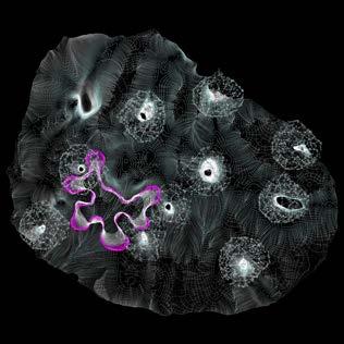
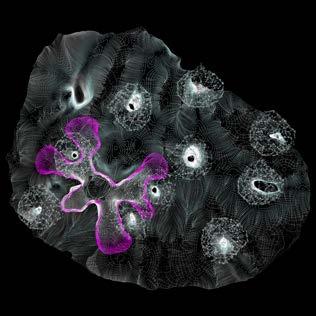
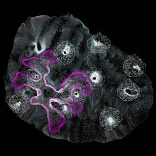
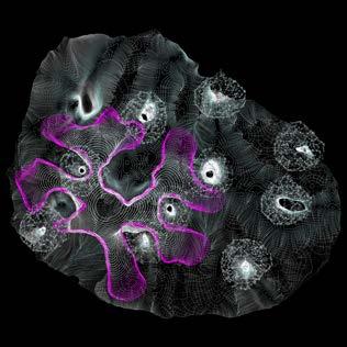
Finally I want to conclude with the sculpture from the same artist Taking a Wall for a Walk, Grizdale Forest, UK, 1990, (image 12), because, in my opinion, is able to sum up the concept we went through so far. The image shows the dy namic of the pattern winding in the forest, and most important, the ever-changing landscape, that over time is coming into possession of this new synthetic extension placed in the natural realm by the artist. The growing moss let us understand dy namics of the vegetation, like which part is probably more or less exposed to sun, humidity distribution, and that with the right material is possible to let the natural landscape take over the new infrastructure and make a resource out of it.

The societal trend is building out-of-human-scale inhabited centers. We witnessed in the last three years how strongly centrally structured societies can show impor tant weak spots, able to bring such organizations to their knees. Today’s technol ogy development, guarantees us the potential to embrace and take advantage of the interconnecting infrastructure, which we will define as the Noosphere and aim to bring together harmoniously Humansphere and Biosphere by re-structuring the existing Urbansphere.
The building has become an old heavy machine, a structured system that lacks evolution. It requires radical changes not limited upgrades of construction techniques. It represents a system incapable of self-sustaining, demanding an increasingly amount of energy and resources for its preservation.
Just recently we witnessed the emerging trend in research and development of new construction techniques, in other words, the implementation of robotic fabri cation in the construction industry. The introduction of new machines in the building landscape represents the radical change we were waiting for, able to reinvent such stagnating industry, bringing higher efficiency. The application of robotic techniques in the construction sector allows to reduce emissions linked to activ ity on building sites and emissions derived from the amount of used material. Currently we can refer to the upcoming trend of 3D printed housing and other minor infrastructures: the employment of robotics deposition systems (industrial 3D printer and robotic arms) and so-called micro-fabrication allows to reduce the amount of structural concrete required by up to 75% and the amount of waste and by-product produced significantly. Not only does the solution make the pro cess more sustainable, it also improves health and safety conditions as robots are the ones doing the hard labor whilst workers supervise the process. The largescale 3D printing of concrete ensures cheaper, faster, safer, and more environmental-friendly concrete construction. In this idealizing vision although, housing concrete, given as well the reduced amount, will still leave behind an important carbon footprint, along with the long list of traditional construction material.
Machine
It is not only about how we produce and fabricate, but also about what we de cide to build and produce. These new machines and methods are opening to us a new world of possibilities, where human can start a new way of living, more integrated with our truly firs home, our planet. Decentralize and reduce pressure on big cities is key point for the architectural quest that wants to restructure the system of cities as conglomerate of old machines is to push and blur the border between nature and human habitat to create an innovative biobased, ecosystem to settle and coexist.
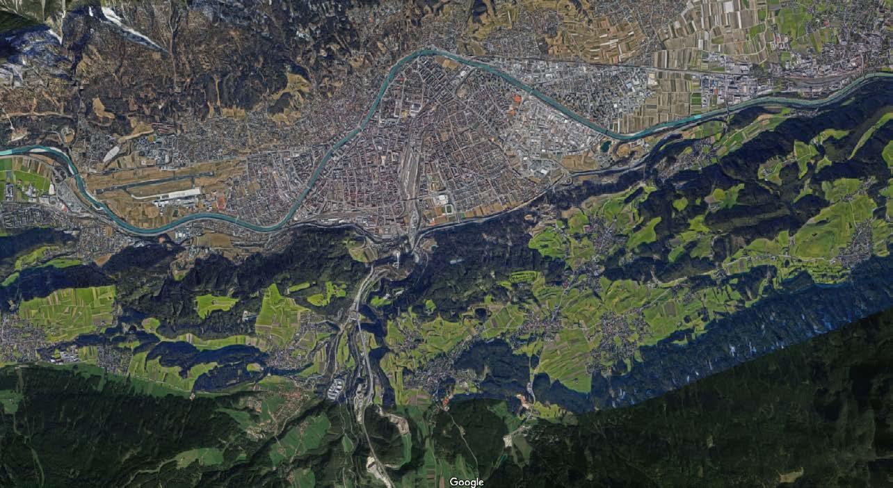
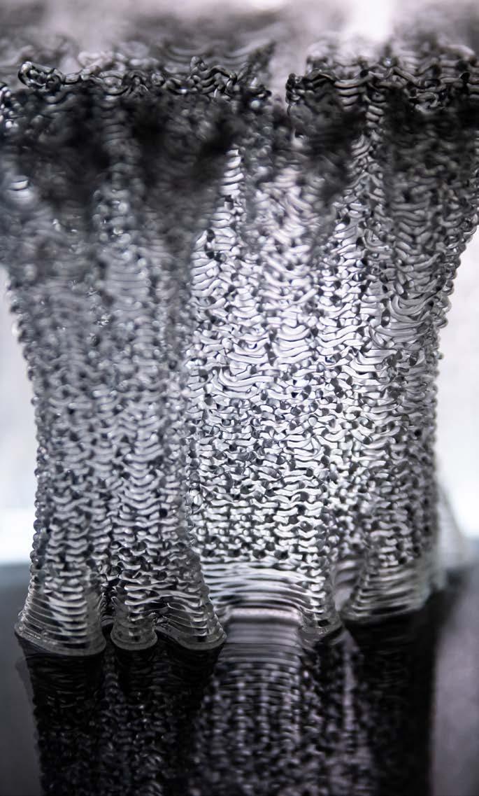
In the process of creating new human habitat t is fundamental first to understand deeply the machine and later on gradually abandon the idea we have of the machine as “being” existing on its own and consider it as an extension of human domain. We have to introduce the machine in the natural landscape and let it integrates, becoming less invasive for the environment, adapting to the human scale and enabling the machine to establish a direct channel of communication between itself and the surrounding environment. With the term “Machine” I will refer to the working ecosystem of fabricating robots, receptive devices and com putational algorithms. The machine provides real-time feeds of surroundings and via scanning technique, it collects useful data to map the environment and obtain high-resolution point cloud. The point cloud will then run through algorithms able to extract all the information necessary to create a data-driven response of the machine to the everchanging landscape. The machine will consequently behave based on feedbacks looping back and forth between machine and natural en vironment. In our case, the environment chosen for the machine to act and react in will be the forest scattered around the location of Innsbruck. Through this trans formation the cold and detached robot will transform in the biological machine capable of creating a habitat, divergent from current paradigm, branching out from the anthropocentric urban realm and reaching out to sync with biological ecosystems. This new living infrastructure will grow and develop anywhere in the globally-interconnected Urbansphere fully aware and conscious of surrounding environment.
Human will therefore integrate biological machines, adaptable to different liv ing protocols, environmentally interactive and conscious of the metabolism of the overall ecosystem, in order to construct new decentralized habitat with reduced environmental impact. Human will inhabit a Urbansphere challenged by multiple natural ecosystems and landscapes and adapted to grow in these latter, creating a balanced equilibrium with organism belonging to the ecosystem.
Brought to light these concepts, fundamental to the process of my research, I ex plain in the following section the approach taken to work on my master theses.
I will first investigate alternative materials to concrete, but able to offer a similar structural integrity and functioning; secondly, I will move my focus to machines and the deep understanding of robotic fabrication and 3D printing. Only after having collected sufficient insights regarding the mater, I will work on the compu tational process that leads to fabrication to be programmed as a more dynamic living system, allowing machine to become part of the living project, and resulting eventually in the integrated biological machine.
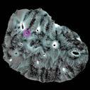
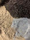
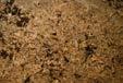
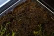
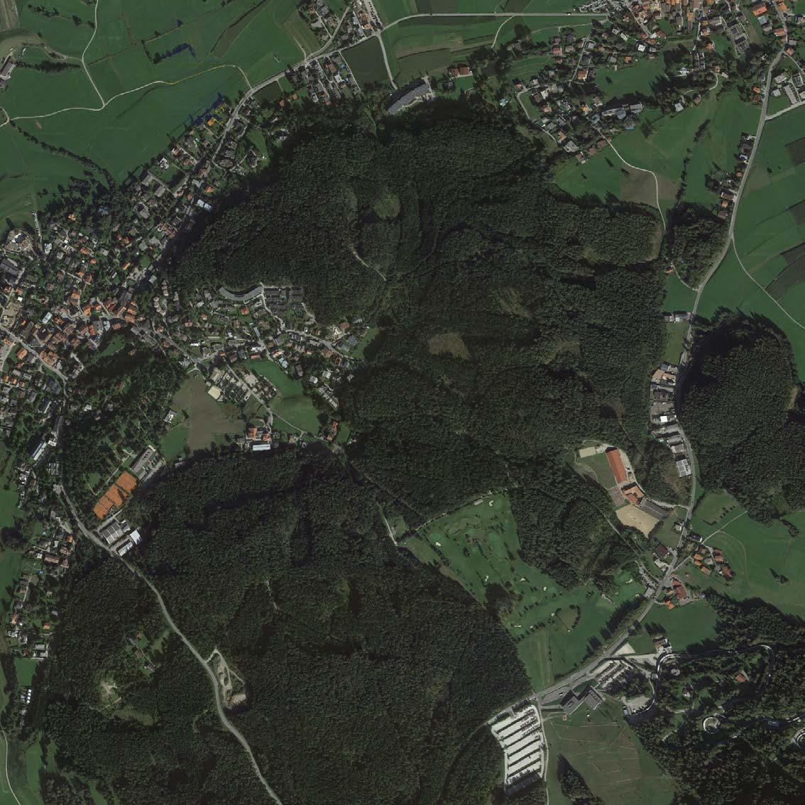
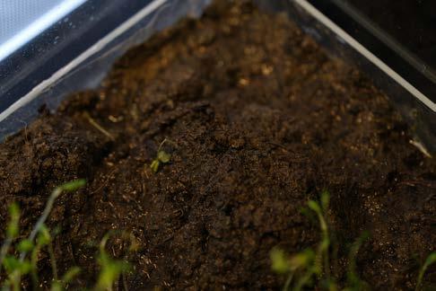
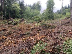
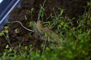
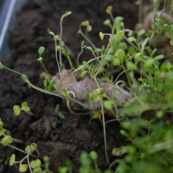
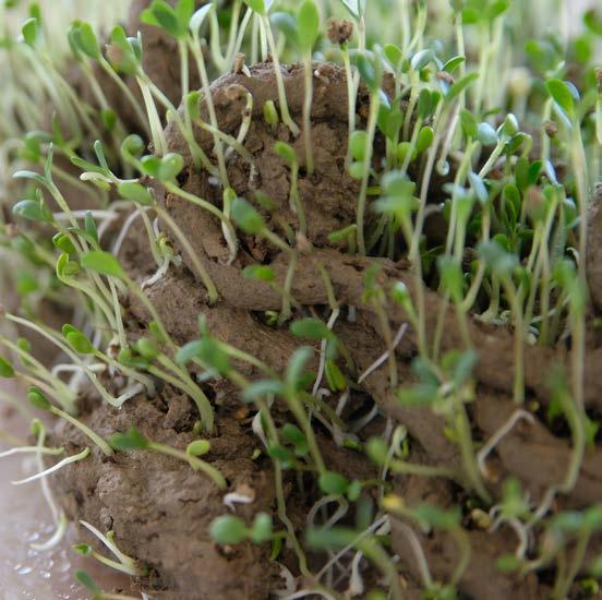
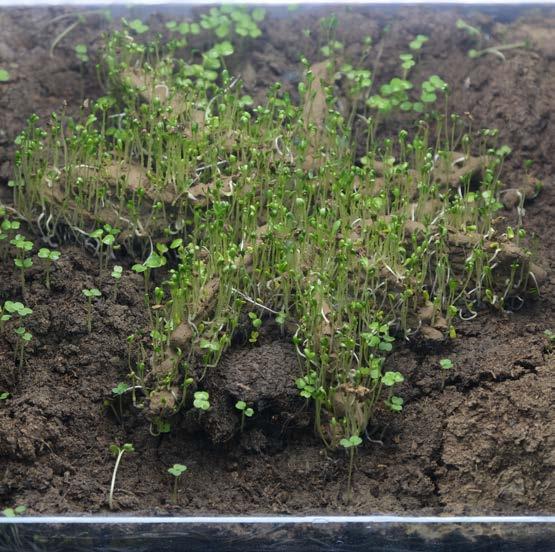
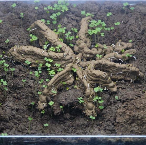
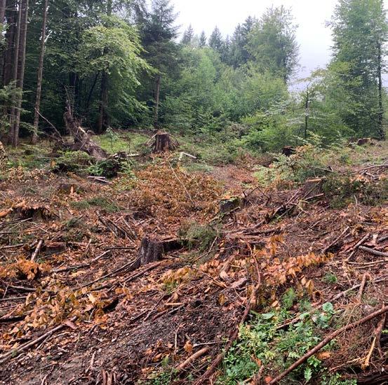
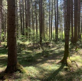
On those assumptions and investigations I will from now on move my focus first on the material system of my project and the deep study and understanding of the surrounding natural environment, which, as previously stated, will be the alpine forest outside the city of Innsbruck. Before choosing this location as final site, I conducted further investigation on local biological materials. Images 13 and 14 are pictures taken during survey on site in the forest of Igls, Ullwald.
Every design and shape in nature has a reason and a function, is the result of a continous evolution. On this basis, the design will be dictated by the rule of nature for the sake of natural realm. I follow the pattern and milestones laid by the Land Art movement, and advance introducing robotic and digital techniques to the matter. I imagine an algorithm that could evolve like nature does, able to imitate, employing real-time data-driven processes, the self-sufficiency typical of working ecosystems.
Changing territorial structure and shaping landscape is what define the Anthro pocene. This definition is not negative per-se, and therefore, I evolve to positive acceptation the act of re-shaping landscapes using non-anthropocentric criterion.


My work will therefore consist in understanding how machine can help us creat ing new environments, adopting more sustainable material and methodology by generating new behavioural pattern for the machine, intended as, previously stat ed, the working ecosystem of receptive devices, computational algorithms and fabricating robots. Whether we use robotic arms, drones or rovers the final results will present no difference to my research, since such technological machines have been already deployed in the application field. Although, I still consider foundamental the study of machine, to understand how robotic fabrication works and what is the potential that can be reached based on production stages and different scales of operation.
I will now explain step by step the process I went through to state that machine, if rightly embraced and applied, allows us to generte a better living environment and show how the machine behaves and react to certain inputs from outer envi ronment.
The process can essentially be divided in two macro thematics: the part where I research the world related to robotic fabrication, especially the field of 3D print ing and therefore the material that could be employed in the process, and sec ondly the part where I research the environment and generate patterns for the machine to interact with the spoken environment. These two sphere can be shortly defined as HARDWARE and SOFTWARE, where put to work together they compose the MACHINE.
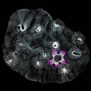
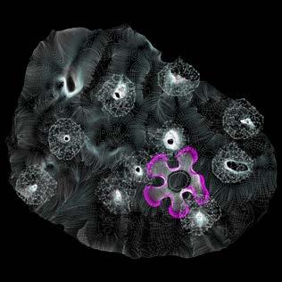
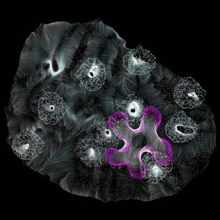
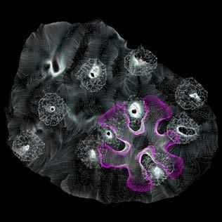
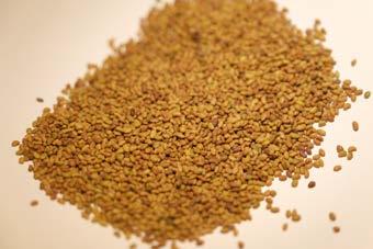
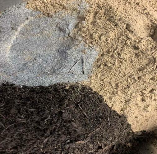
The circular diagram on page 25 shows all the compund I used, mixed in different compination and quantity, to understand how such bio-based materiality reacts to robotic deposition system and viceversa. The compounds are the following: clay, water, sand, soil, biomass and eventually seeds for simulation porpouse. Proceeding in the project, the circular diagram will show which material are being used in the production tests.


Clay and water are fixed elements at the base of each tested extruded mixture.
The choice of clay is a matter-of-fact, it can be considered a more sustainable ma terial then cement, because its extraction is much easier and more direct. Found in nature in form of powder, it allows to cut a large amount of embodied energy, since it doesn’t need further elaboration after the extraction process and furthermore clay presents similar behavior in terms of tensile and compressive strength. The use of further elements will be explained on the way.
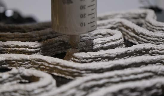
The process to create the optimal extruding material starts always with on-site col lection of local bio-based material, as per illustration at page 27. Sand was collected from river Inn shore and studied subdividing based on granularity. Grain size changes with the location on the bed. This show how natural forces, like the flow of the river, tend to give to material a certain disposition in the natural realm. Wind blows bigger grain, while calm water transport and deposit fine sand under water on the shore.


The first approached mixture to deposit via 3D printer consists of water, clay, sand and soil.
I collected compounds from the natural domain, with the goal in mind to construct using only local materials. For my project is vital that material elements are pro vided by the environment where machines would work in, in order to cut further energy consumption embodied in costruction process.
For this reason, I first added soil and sand to clay and water to create the printing mixture, as showed in the diagrams. I first collected sand along the river shore. The different granularity of the sand allowed me to study the mixture rhealogy, that is how the machine reacts to different dimensions of particles present in the mixture.
Flexible


The machine I started my investigation with is the industrial printer Wasp 4070, arranged by the Synthetic Landscape Lab of Innsbruck University, faculty of ar chitecture.

The following diagrams show attempts conducted to find the ideal mixture for extrusion, tests with different material ratio had to be conducted.
Mixture granularity size had to be adequate to the machine, based on a pressur ized deposition system explained in the diagram at page 28-29.

The catalogue of diagrams (page 31) indicates the conducted test, based on variation of material amount.
From this study I deduced that the key compund to guarantee a good rhealogy, this means the ability of the mixture to flow avoiding obstruction, was sand. The amount of sand is critical because this material does not bind with water as good as clay does, and is not able to absorb water like soil does. Therefore, as the graphics illustrates, the component that endured major variation and reduction was sand.
The mixture number 3 was the most successful between the tests, but investigation has to be conducted taking in account both the machine and the material.


The rhealogy of the mixture is not only dependable from the compounds mixed to produce biobased extrudiong material, but also from the parts of the machine that handle it. Overall mixture number 3 used to flow flawless through the piping system of the industrial printer, although when making its way out from the compression chamber, a part of water used to be squeezed out and separated from the mixture. The major problem presented by the machine was in the extruder sector. , as I will explain in the next page with an appropriate diagram.
The circular diagram (top, page 33) overlaps the material amount used in the tests to show better variation analysis. The graph (bottom, page 33) illustrates instead the drying process of final ratio chosen for mixture to be tested in the printer. It analyses drying based on water weight loss, over 72 hours. The material not only looses almost completely the amount of water mesured through its weight, but also shrinks visibly with evapo ration of water.
The following diagram represents the functioning of the industrial 3D printer Wasp 4070. The material is stored in a pressurised chamber accordingly connected to a compressor. Between this two part there is the manual valve that allows to regu late pressure nside the chamber to extrude the material. The material is injected in the extruder via a 90° injection point, and pushed out using a screw attached to a motor. Mounting the costumized nozzle in TPU the extruder was excluded from the system. Excluding the extruder block brought benefit to material flow, because the 90° fold preventing material passing through and generating blockage in the system was taken out of the process.
To test the mixture and understand the interaction with the machine I produced a catalogue of complex shapes, based on steep angles, overhang and geometry rotation and twisting. A custom TPU nozzle was developed to guarantee flexibil ity during printing process (see page 36-7).
The Wasp printer offered a vast potential, but results were not satisfactory in terms of layer deposition precision due to the extrusion method. The complicate rhealogy of the mixture did not guarantee a good flow and deposition firstly due to the manual valve that controls pressure level and secondly because of a 90° injec tion point along the extruding system, visible in the illustration. It is possible to watch the video of the extrusion by scanning the QR code in th enext page.


Therefore I switched printing set-up to one that could guarantees higher precision and definition.
I customized the printer, designing an extrusion system that could be more direct on the material and controlled and adjustable by the printer itself.
To continue testing I used a Creality CR-10, a basic 3D printer that on the bright side is open source and easy to operate on.
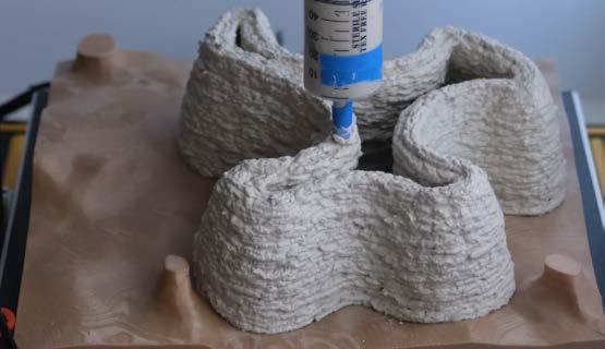
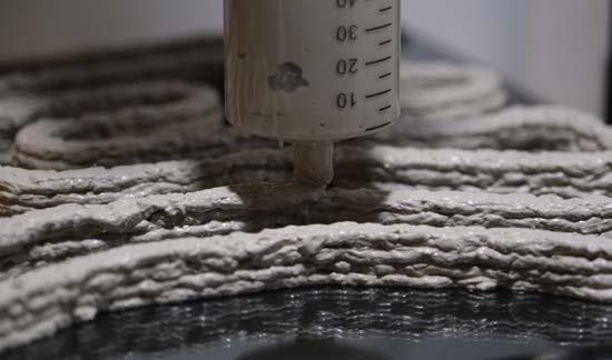
To achieve that I connected a reversed stepper motor in the Arduino card con trolling the printer. The rotation of the motor push down a screw- operated piston that finally extrude the mixture out of a syringe. Syringe and motor holder, along with the piston were all designd and later printed in robust PLA.
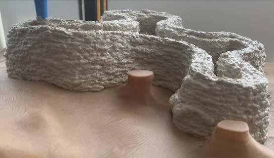
This new set-up, working with algorithmically generated codes [.gcode] for the printer, allowed me to produce case study models with higher definition, and an acceptable loss of only 1/4 of the printing room.
Adjustament to the mixture rhealogy had as well to made, since higher definition and extrusion size reduction mean dimension variation in the particle.
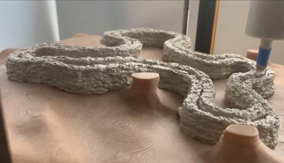
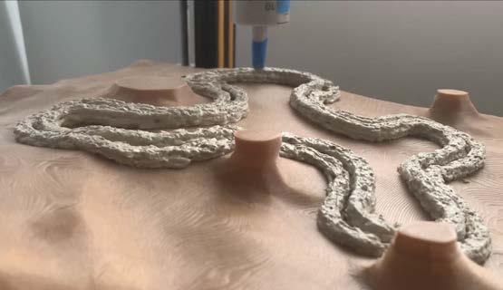
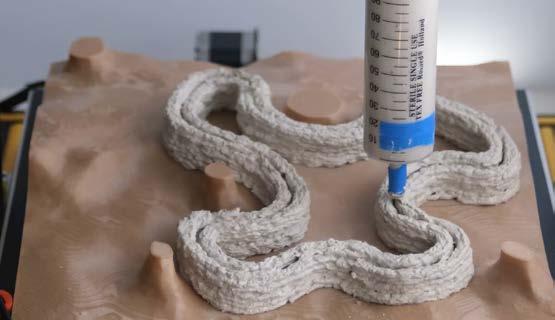
To have a higher and more direct controll on the machine and what this would have produced, I produced an algorithm of which outcome gave the machine complete freedom of movement, enabling full potential. Thanks to this [.gcode] generating script, I embraced NON-PLANAR print for all the subsequent model.
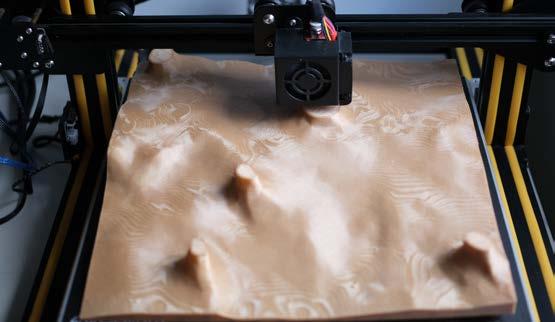
This step is fundamental to allow the machine to move freely in the processed en vironment, without needing to bring any change to the landscape it will establish interaction with, avoiding to spoil and destroy existing local ecosystems.
The diagram display the final composition of the printed pieces connected to the motor via the screw bar.
In this case I tested dif ferent size of holders and syringes, and eventually, found out that a 150 ml syringe was the better fit for such set-up. A 100 ml syringe mounted on a smaller holder also worked just fine, to the disadvantage although of the amount of material and therefore last of the printing. However, a larger syringe would have generated an excessive pressure, disabling the limited power of the stepper motor.
X axis carriage
3D printed holder
& connection
piston
stepper motor rubber plug syringe


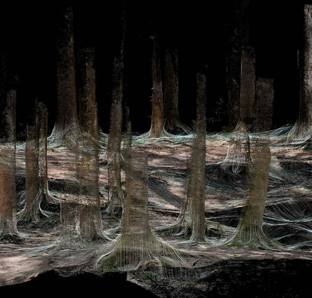
So far I investigate the HARDWARE, or rather concepts limited to material and machine. The next step is to understand and design a protocol that let the machine behave following patterns that reflect the environment they are placed in. This will represent the SOFTWARE part of the machine.
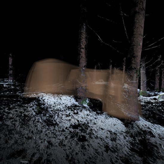
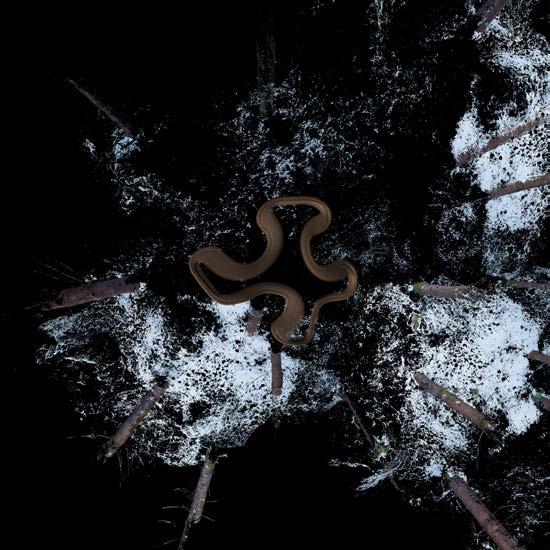
The environment I choose to conduct my experiments is the forest. The reason is simple, I want to re-evaluate this environment through protocols drawn by a machine that will be more and more biological.
With the term BIOLOGICAL MACHINE I mean a machine that interacts with the ecosystem, creating new pattern observing the sorroundings and acting accord ingly, to build on offsetted infrastructure rendered as the habitat that does not have to be intended for human only, but also as expansion of the natural realm, taking advantage of what the machine creates using computational designed patterns and the local bio-based material so far investigated.
During the pandemic a claustrophobic feeling has developed towards the ag glomerates of old and heavy machine that is the city. We gain consciousness of how vital is the natural domain for our personal human sphere and how often we miss a channel to interact with the natural realm.
For this reason I chose to work in the domain of the forest, because places of such natural beauty, provider of relief and well well-being, have hidden potential to produce and become new environments, possibly even alternative to the liv ing-space protocols we have ever followed.
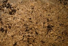
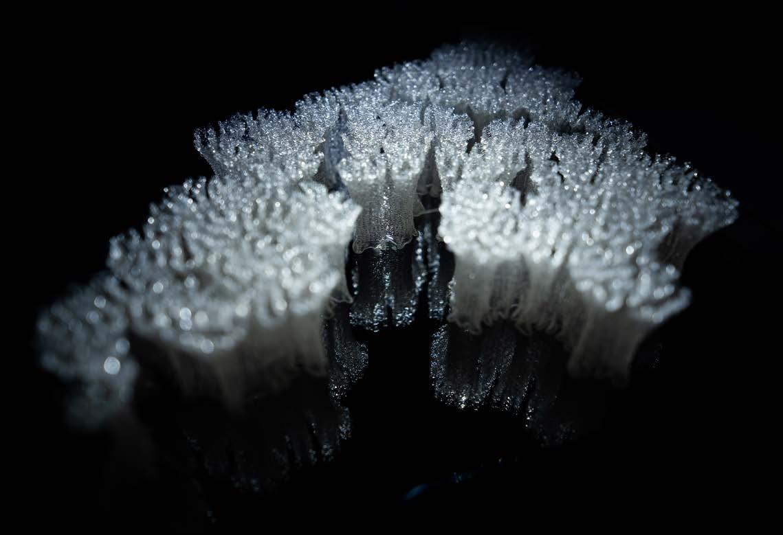
Although I often witnessed neglect and disregard for such natural realm, and in consideration of this I think also forest are elegible spaces to go through re-eval uation. This is the place where all materiality could be found locally in the lesser harmful way, where different type of biomass can be collected, chipped and fab ricated (see picture here beside).
I would love to see the birth of a new infrastructure, that opens innovative channels of interaction between human and the natural realm of the forest, but that simultaneously does not bring any harm to the ecosystem, but instead will grow as an extension of the latter, allowing the natural environment to grow with it, and eventually take over as a new piece of landscape.

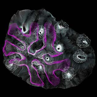
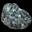
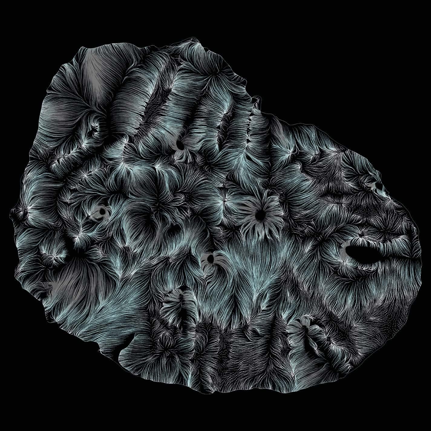
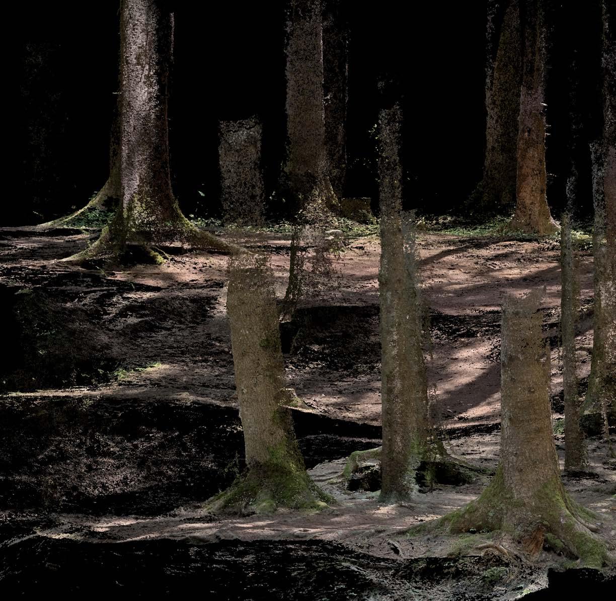
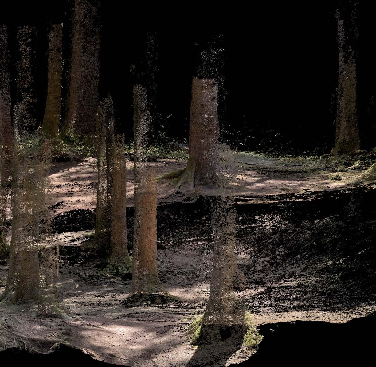
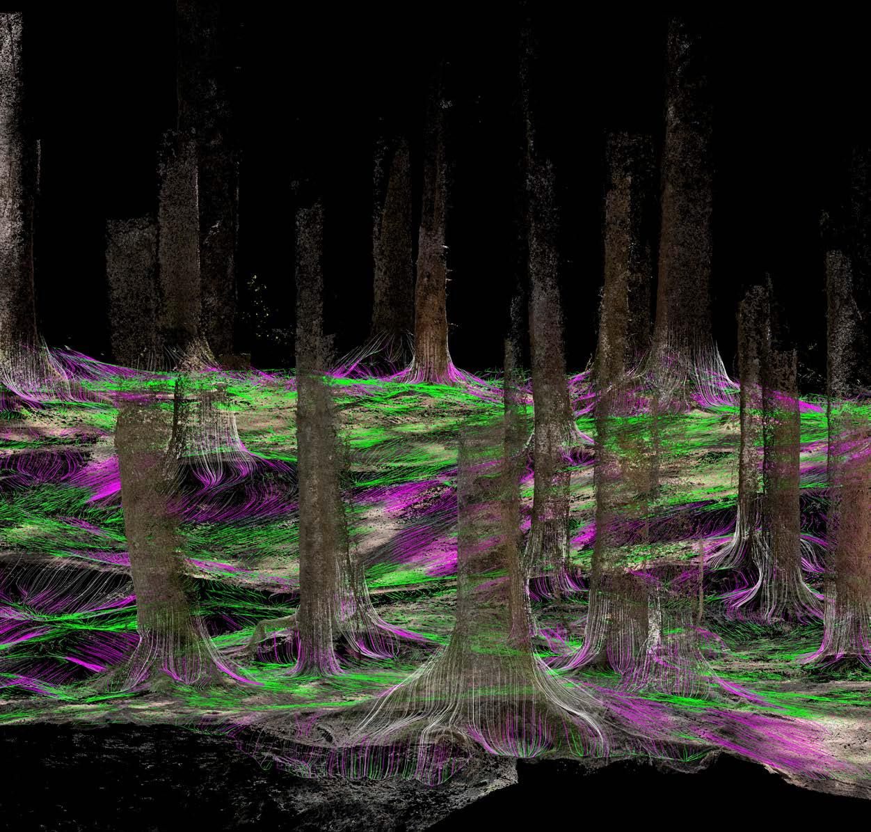
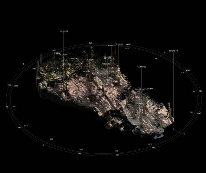
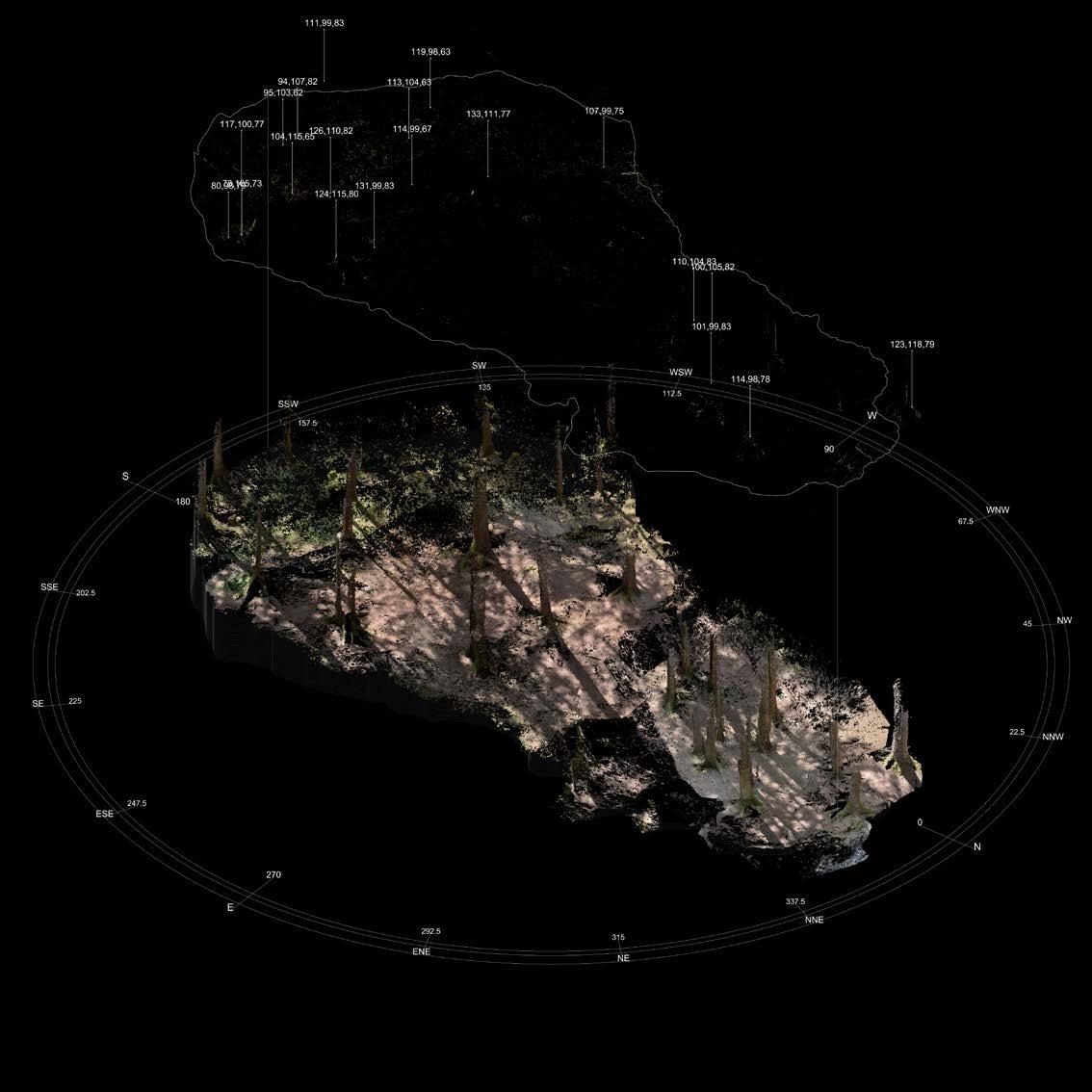
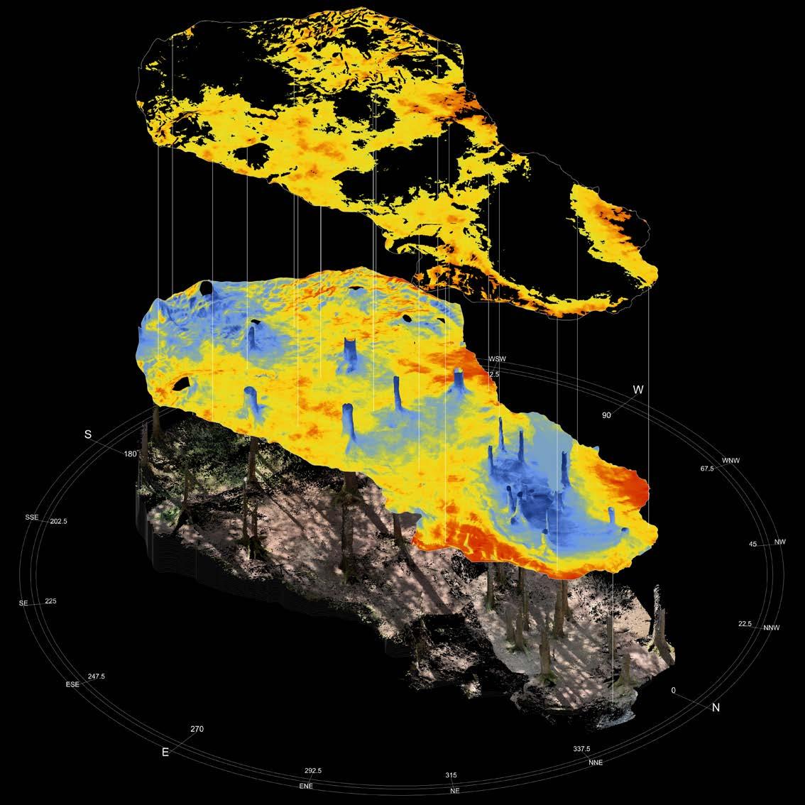
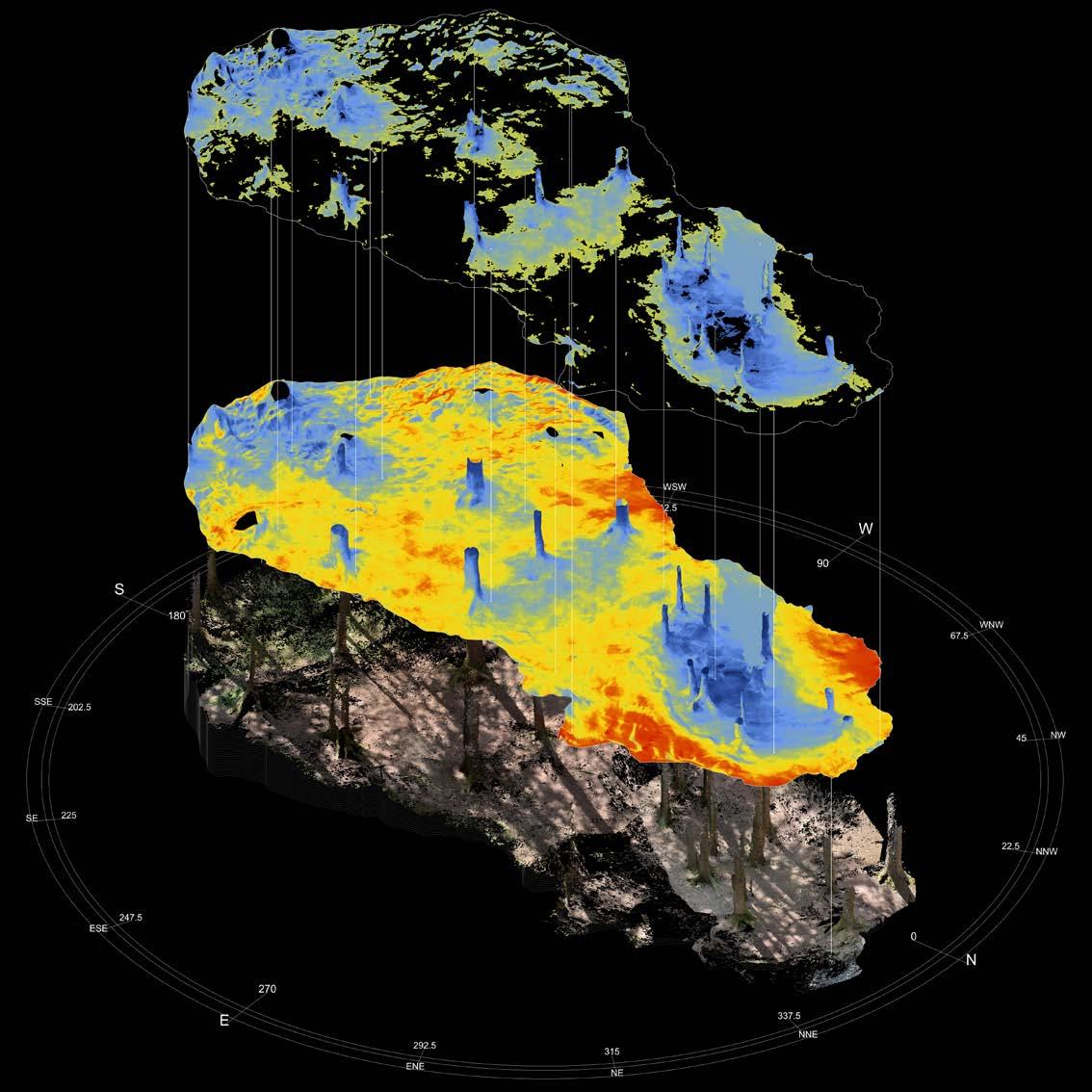
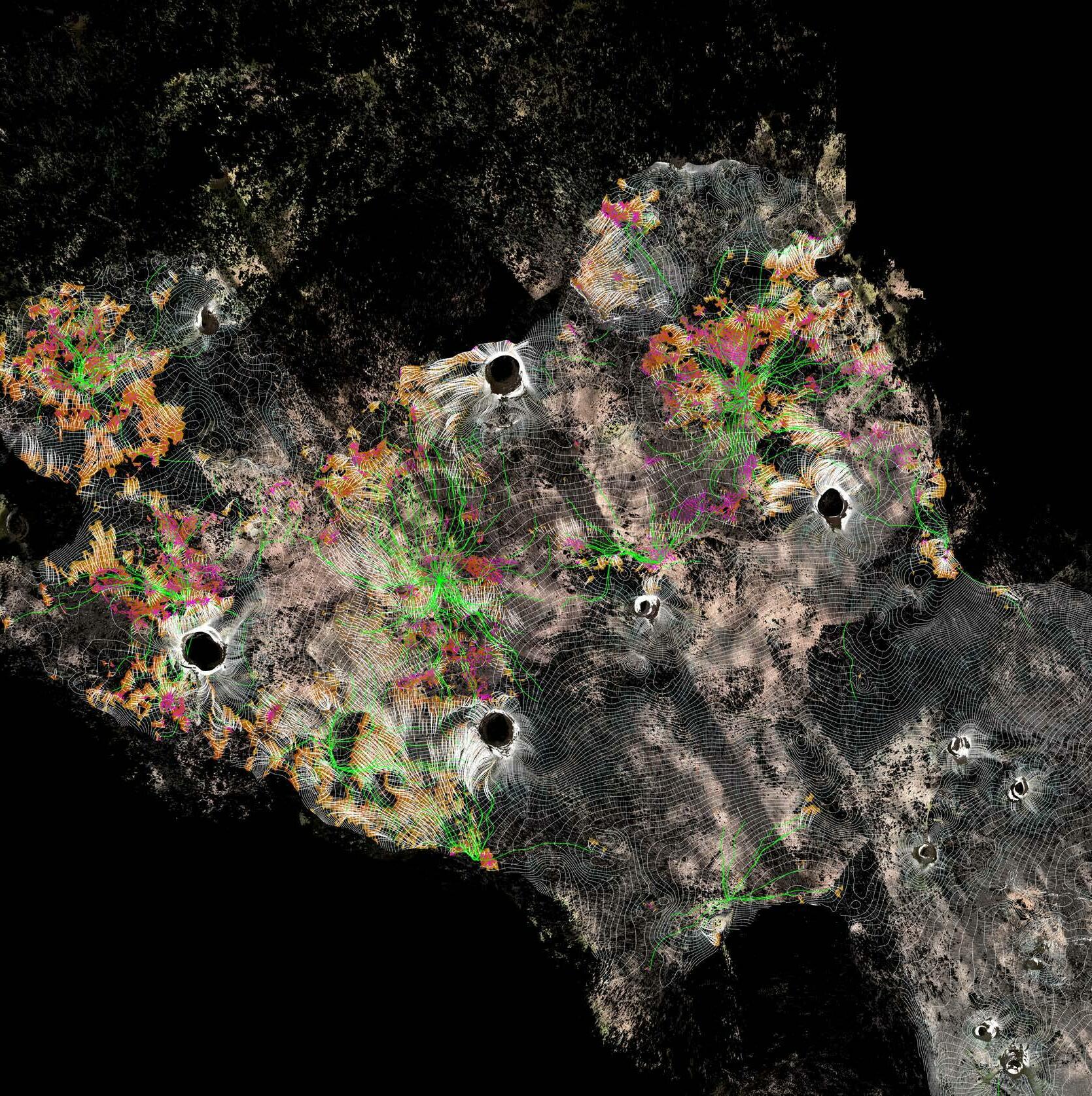
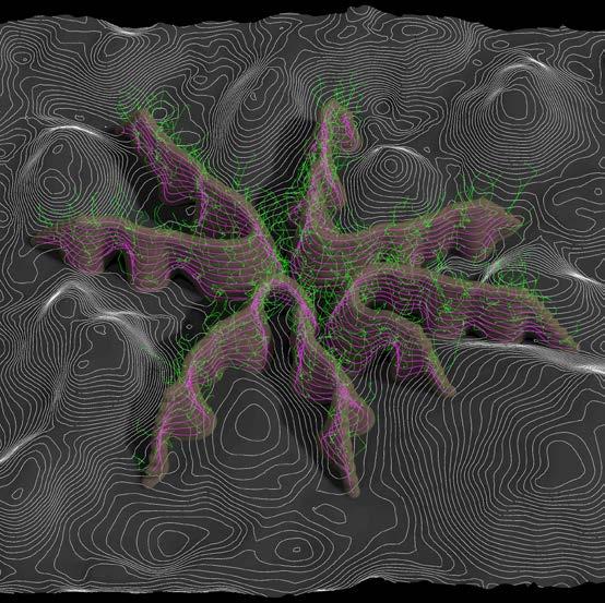
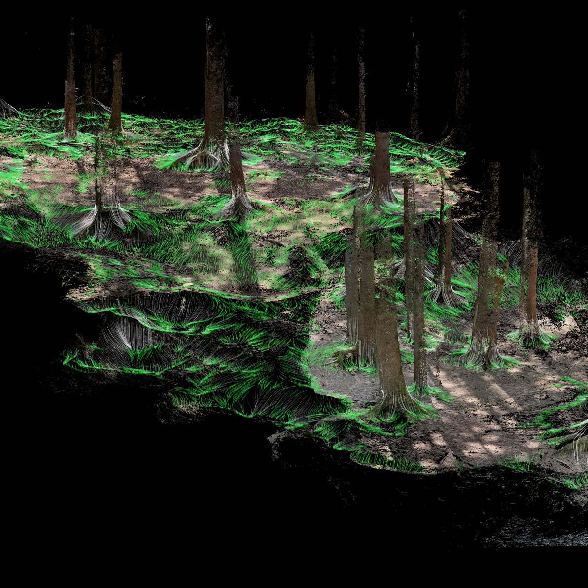
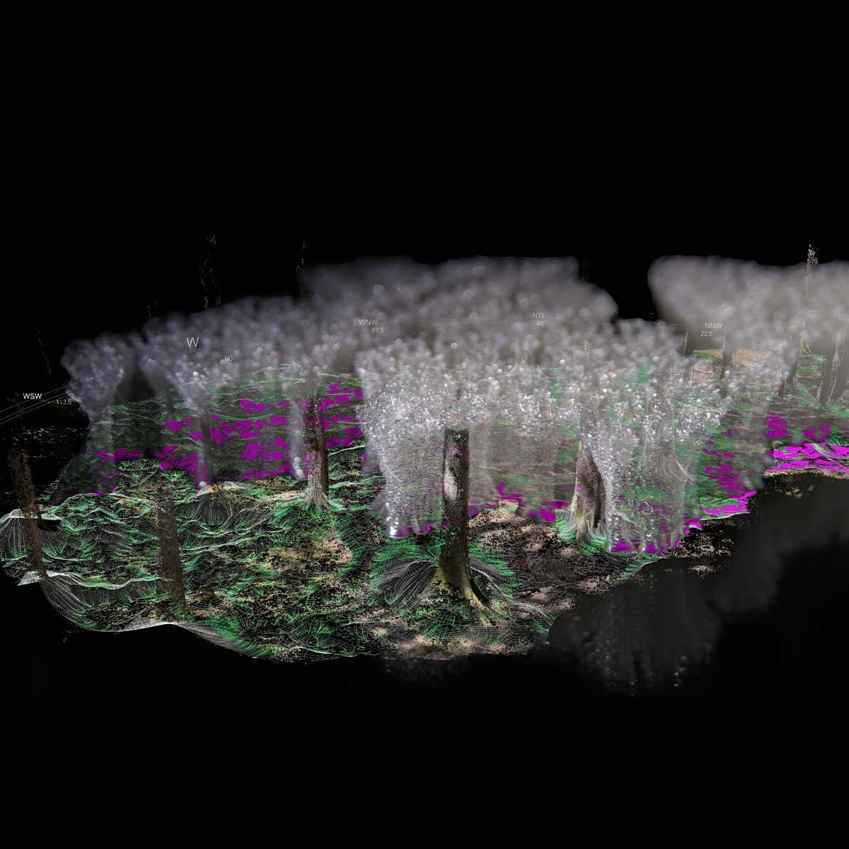
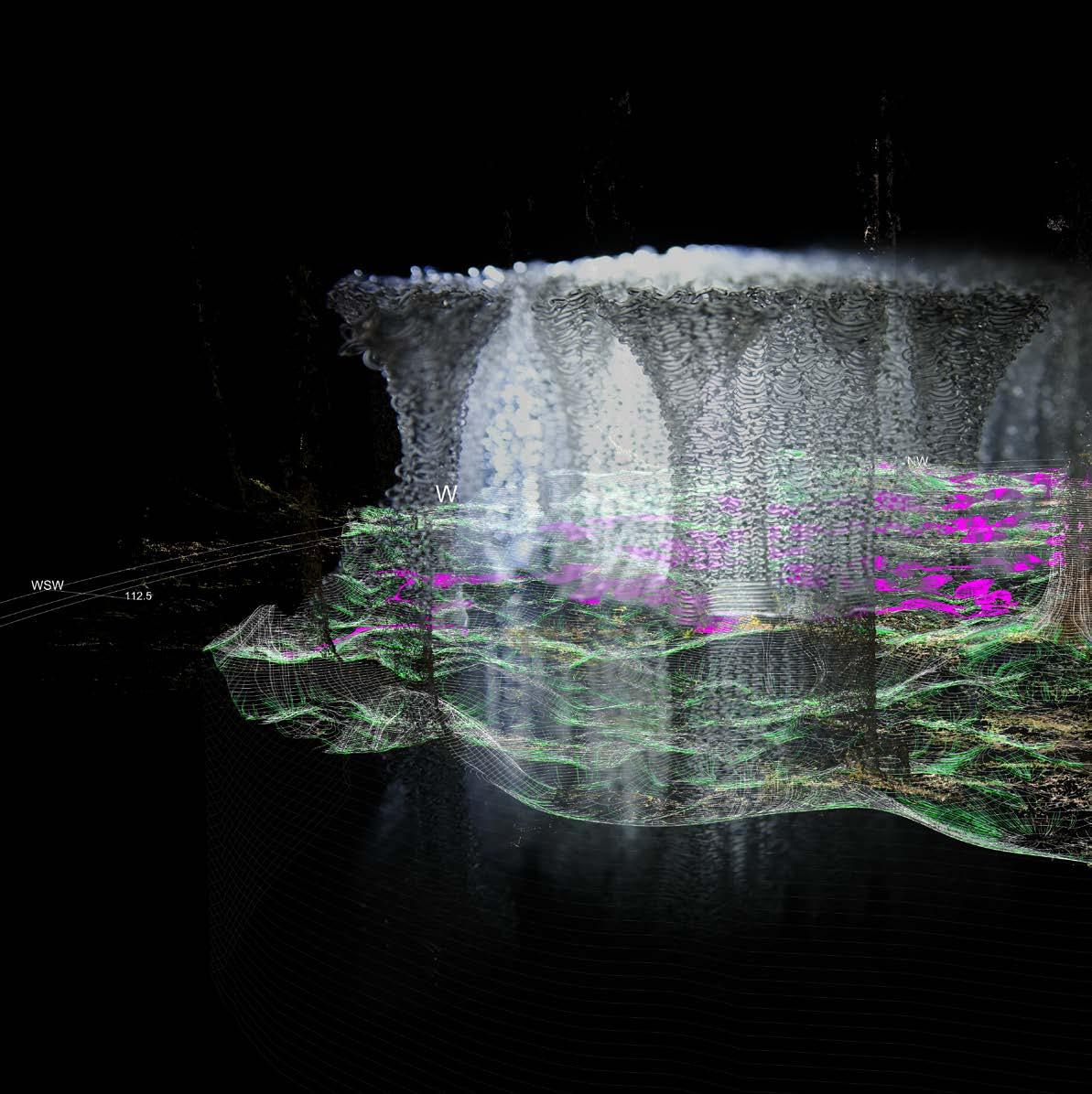
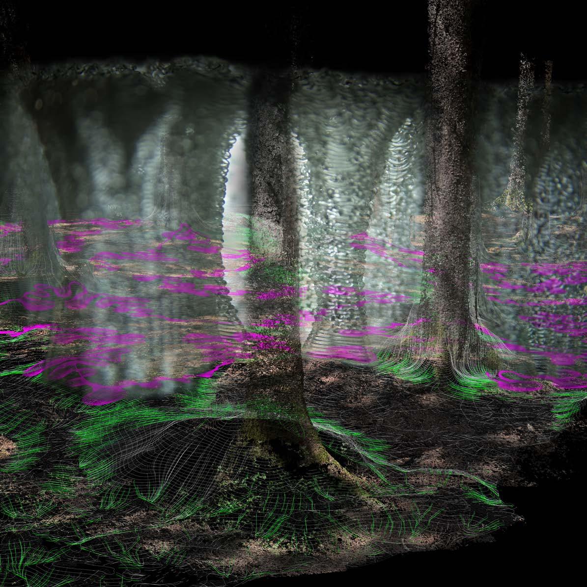
The process of integration of the machine into the natural realm starts by 3D scan ning the environment. I used the photogrammentry technique: it consists in taking multiple picture to the sorrounding environment, extract the so-called depth point, which means analyse pixels by focal lenght and focus information from the cam era to give them coordinates and seccessively arrange the extracted points in space. Therefore each point will present [x,y,z] space coordinates and [R,G,B] color coordinates.
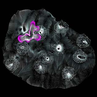
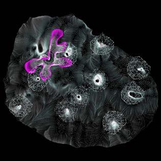
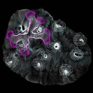
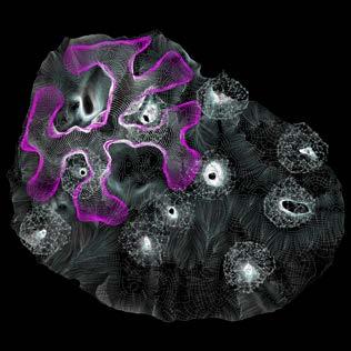
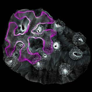
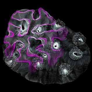
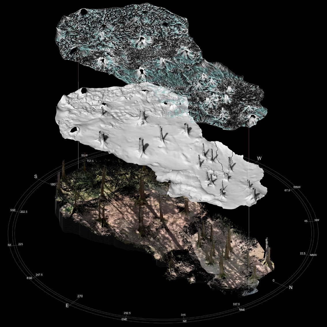
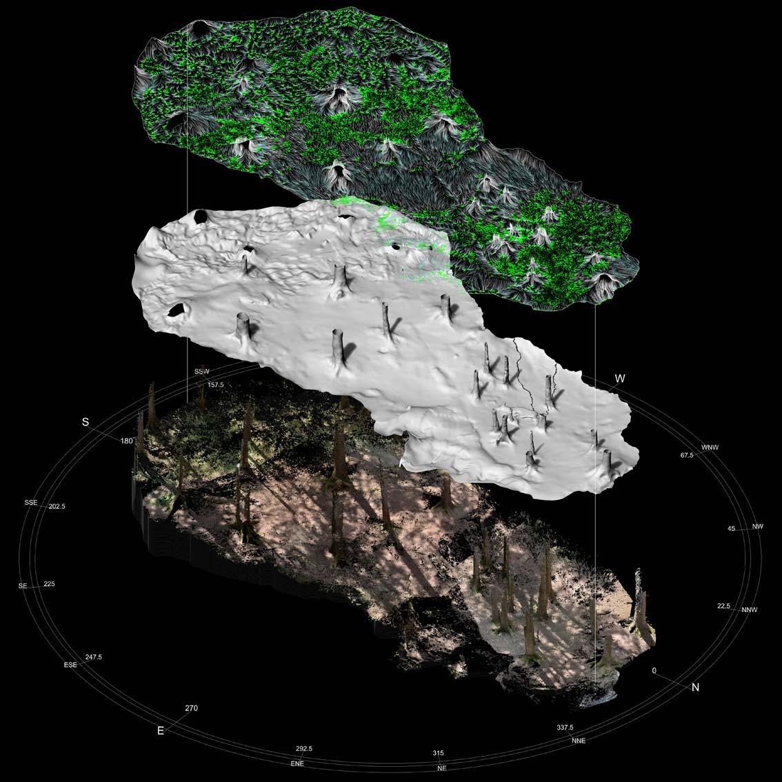
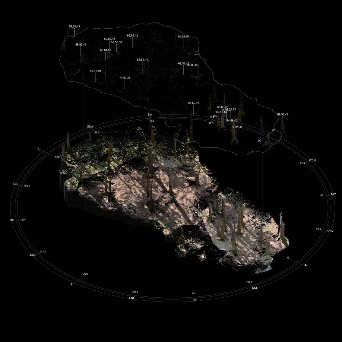
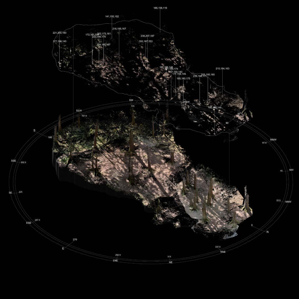
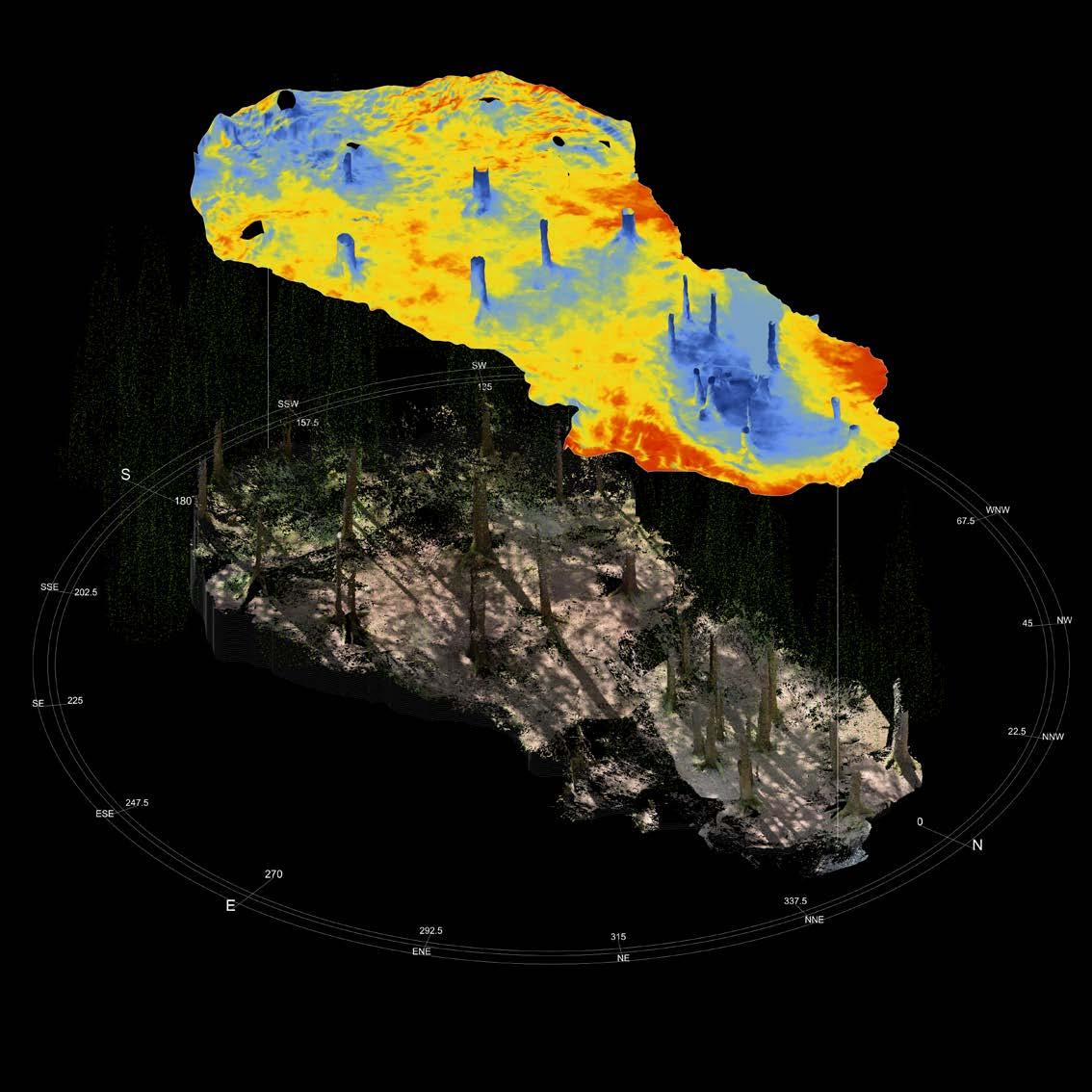
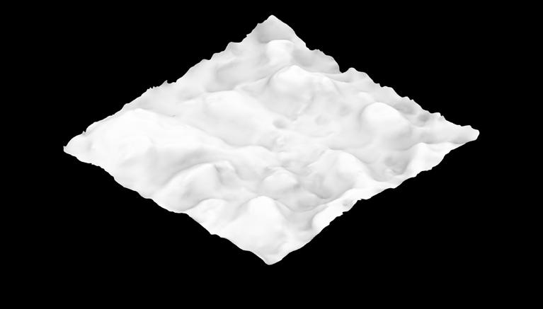
As the following illustration at page 22-23 display, the scanning process produce a point cloud with millions of point, this means a lot of information, some of them redundant or imperfect. For this reason along the process a filtering of points is applied. The filtering process is based on the confidence of each point in the 3dimensional space expressed via [R] value in the [R,G,B] scale.
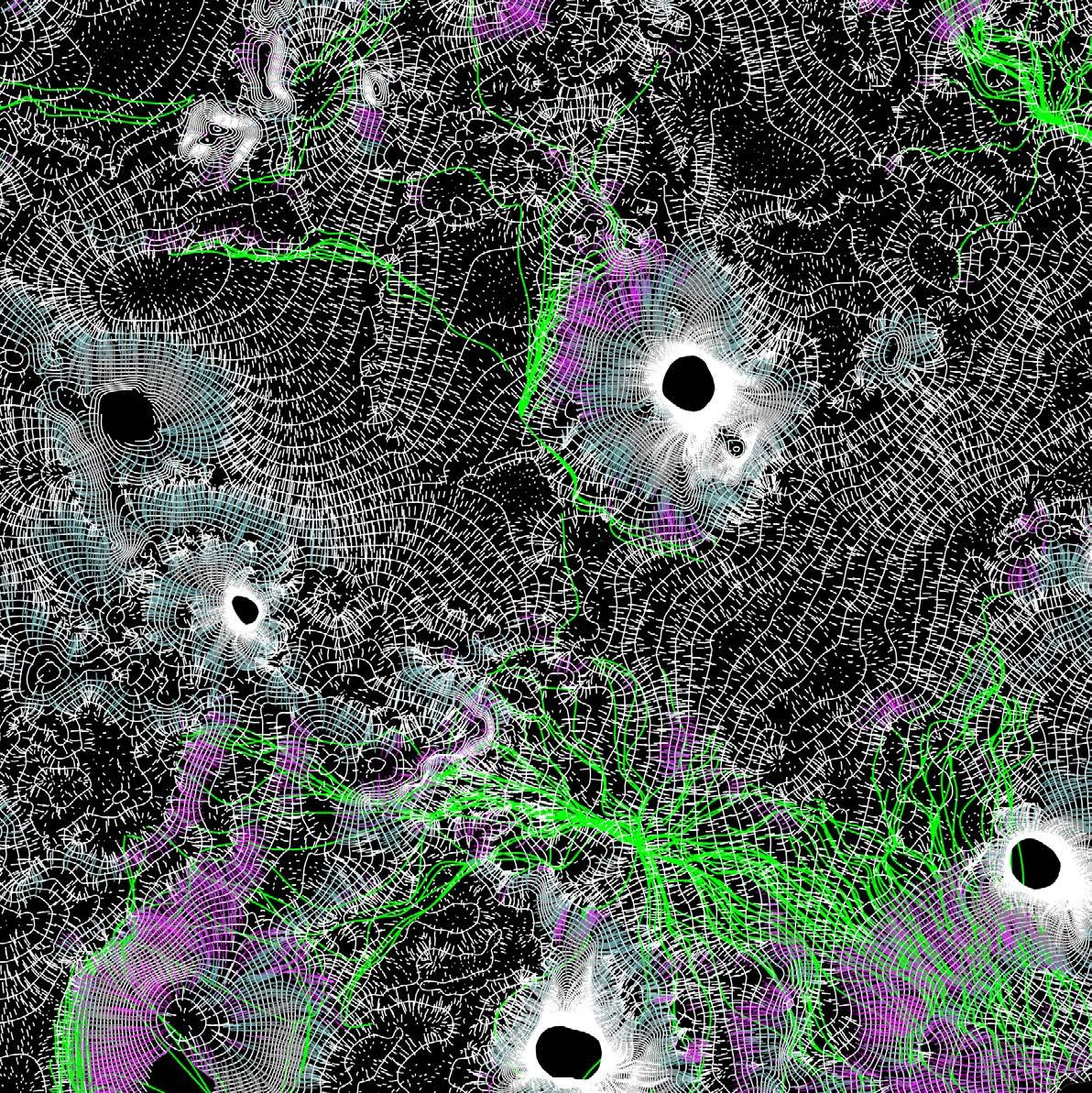
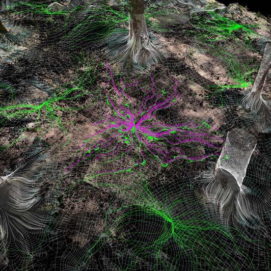
Once the filtering of the dense point cloud is completed, the generation of the mesh is possible. This way we digitally reproduce the natural environment we want to work in together with many usefull data, ready for the machine to be algorithmically processed.
To give an idea of the location I displayed a catalogue of pictures taken to scan the forest area. The catalogue at page 46 comprehends only 6 of the 459 pic tures taken and aligned in the software to produce the point cloud. After points are generated in a “dense cloud”, an algorithm filter them out by confidence, as displayed in the catalogue at page 47.
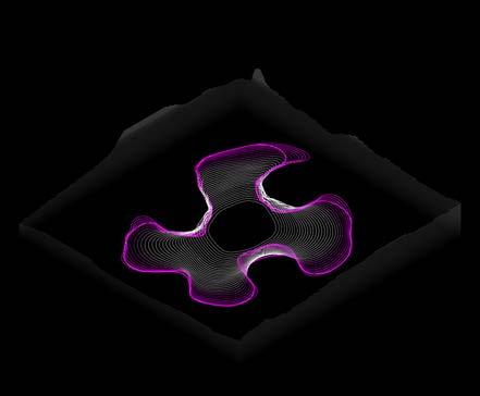
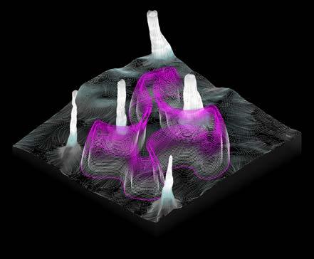
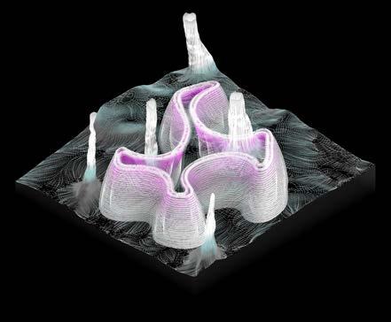
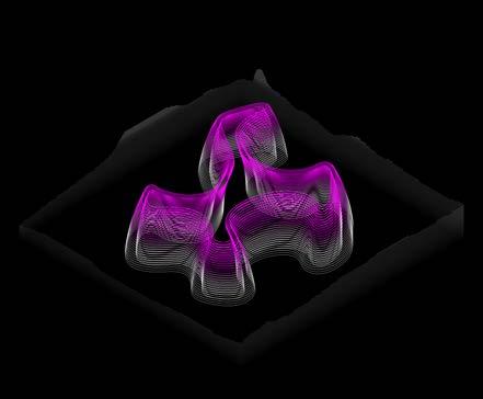
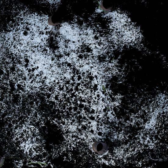
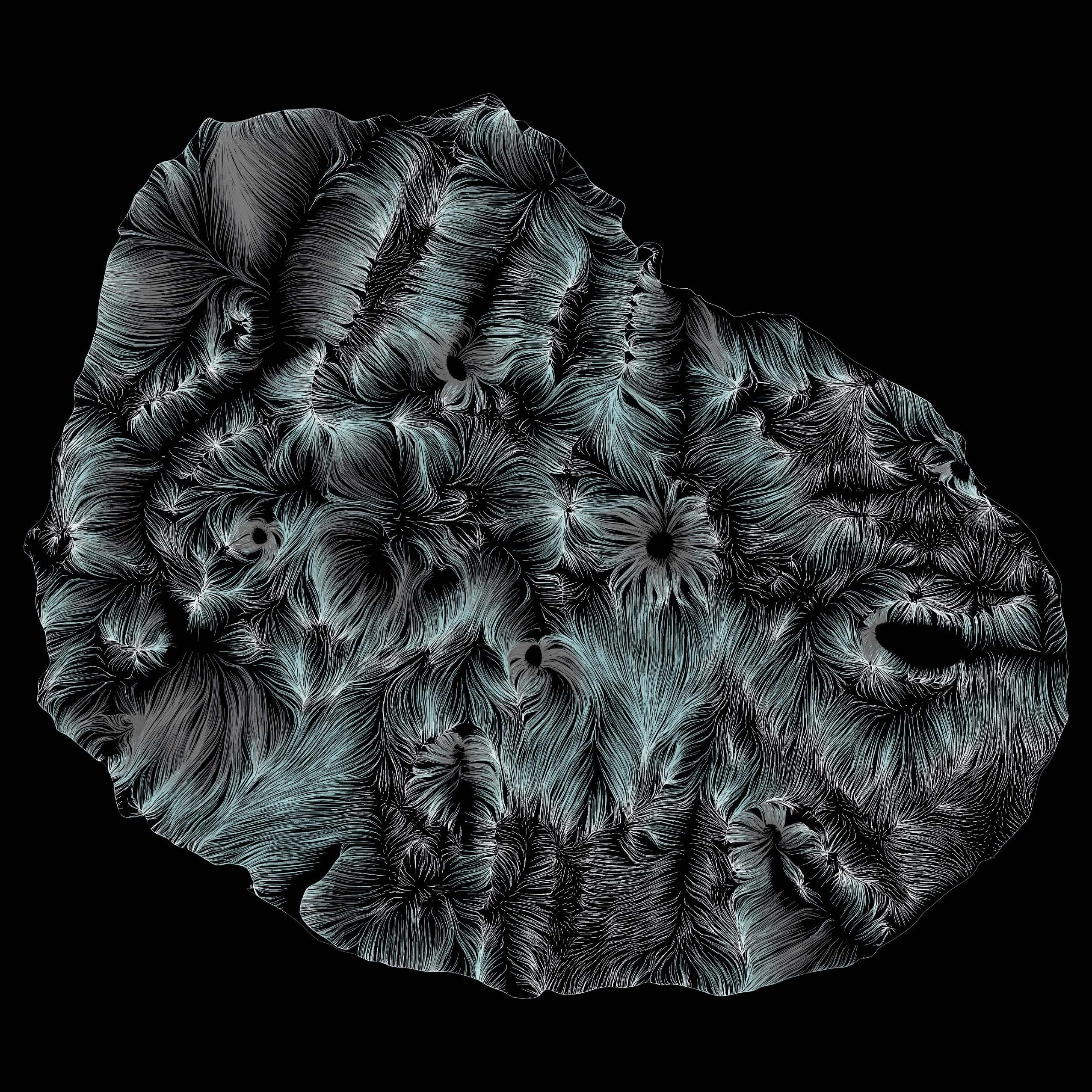
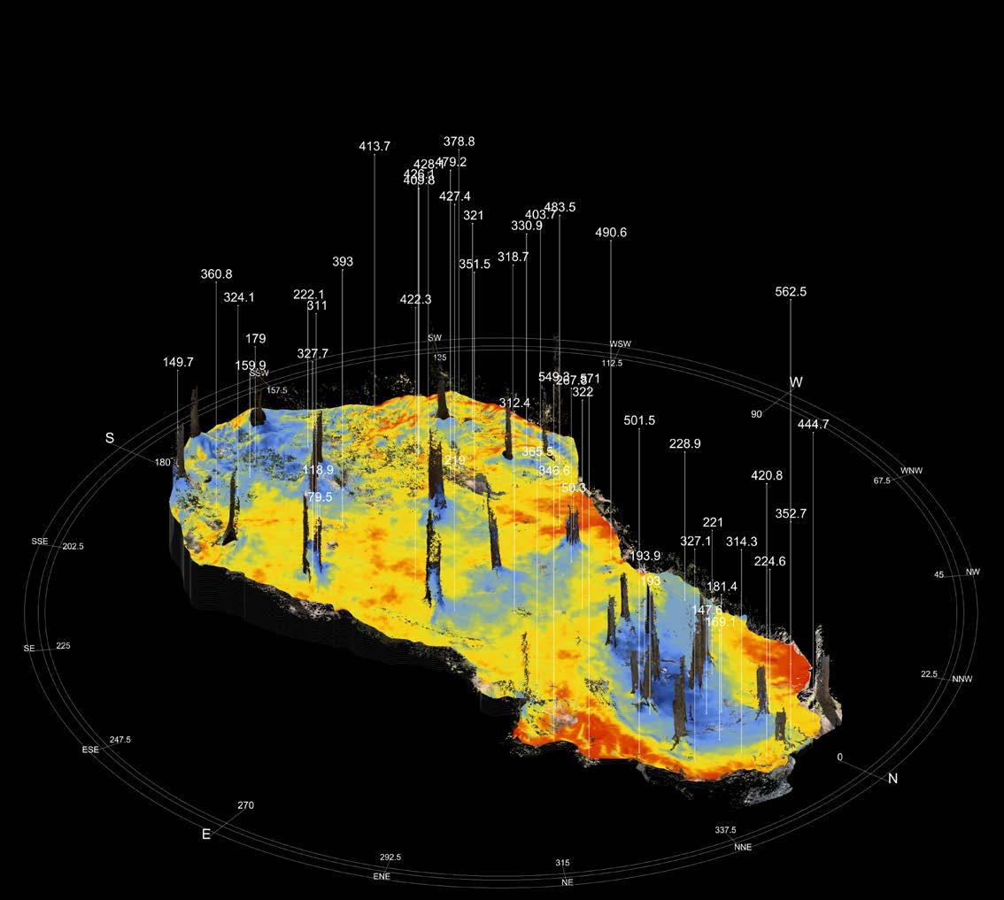
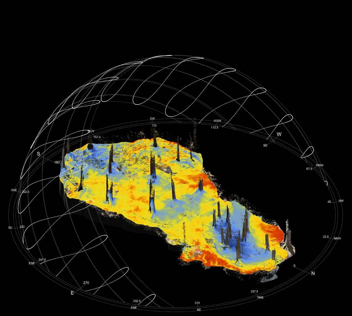
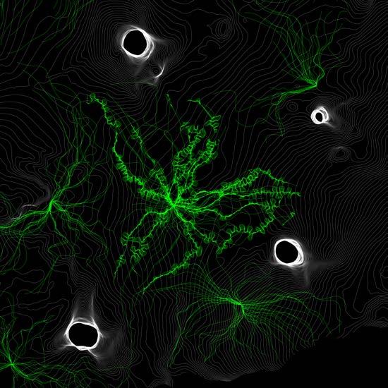
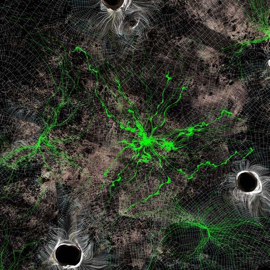
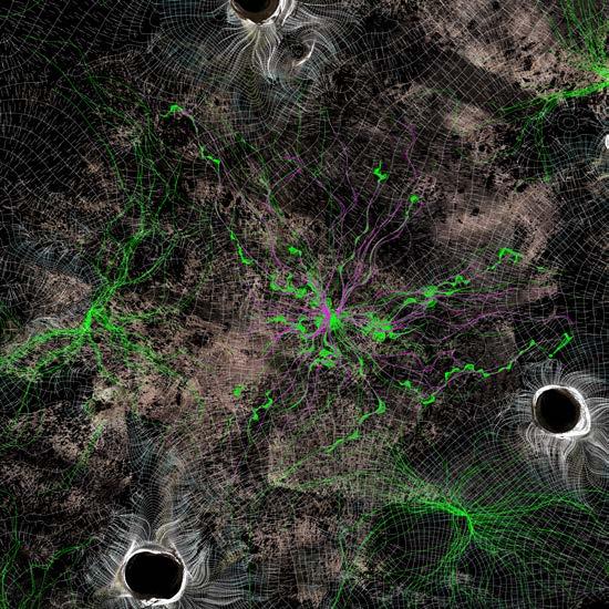
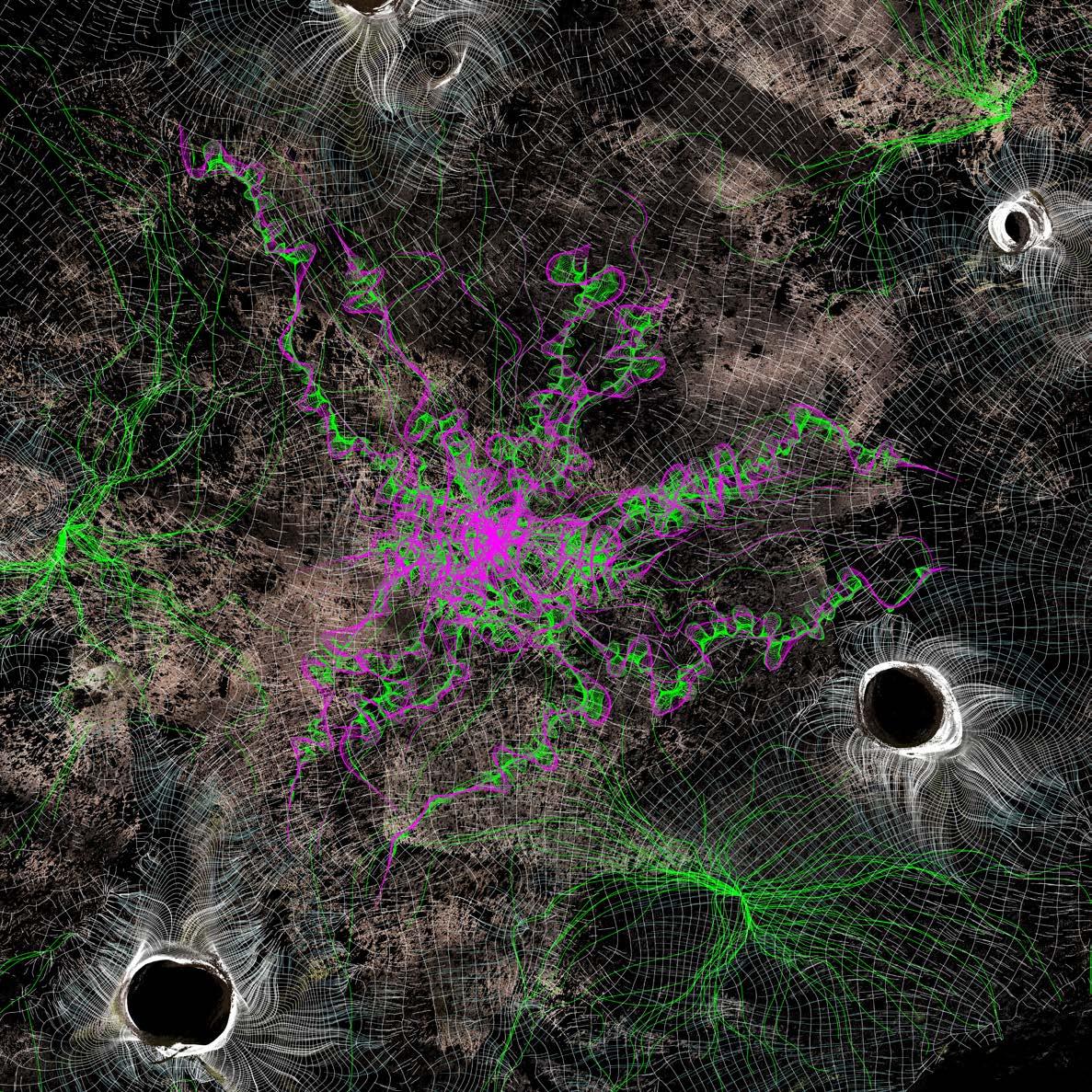
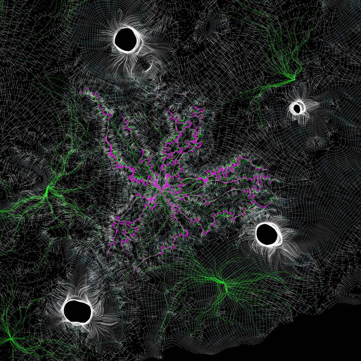
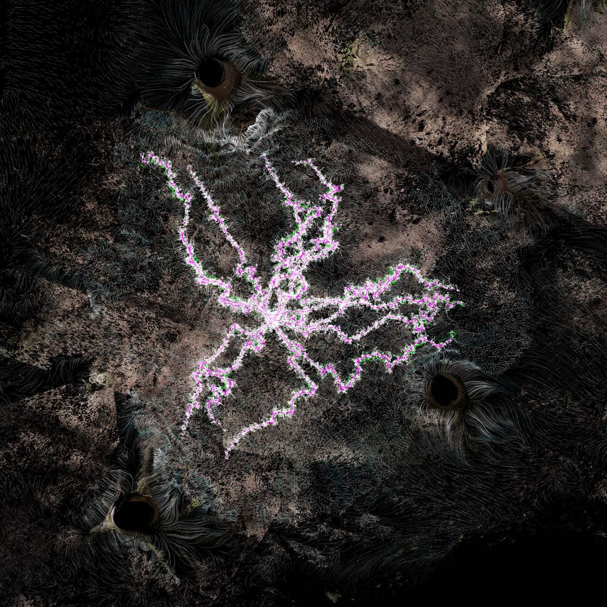
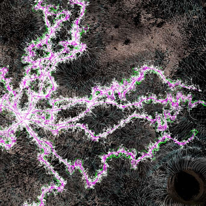
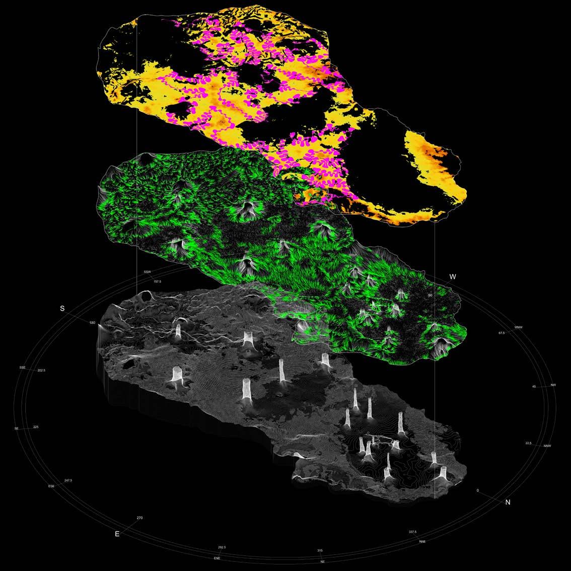
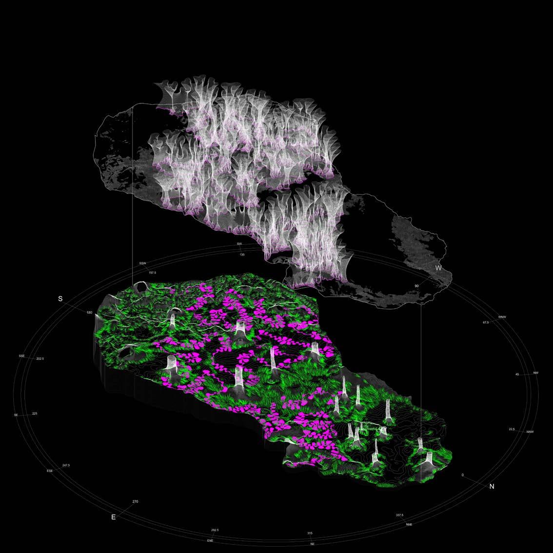
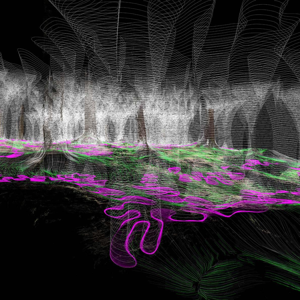
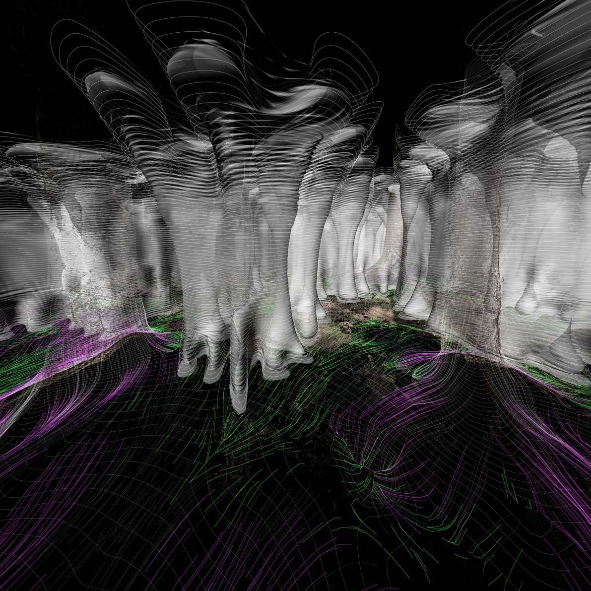
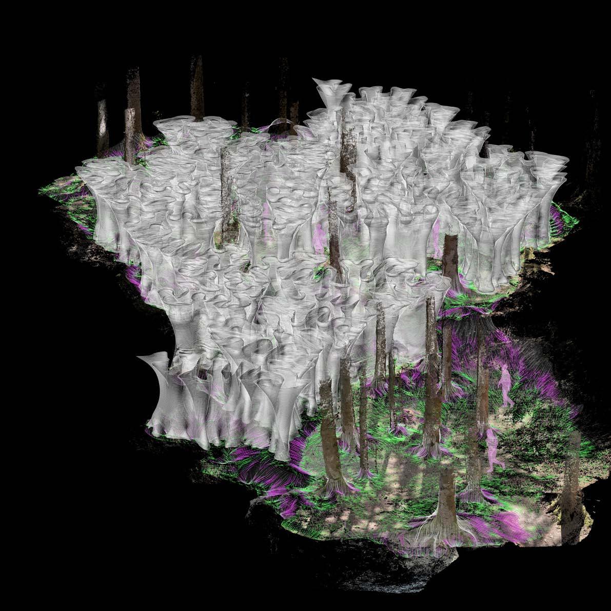
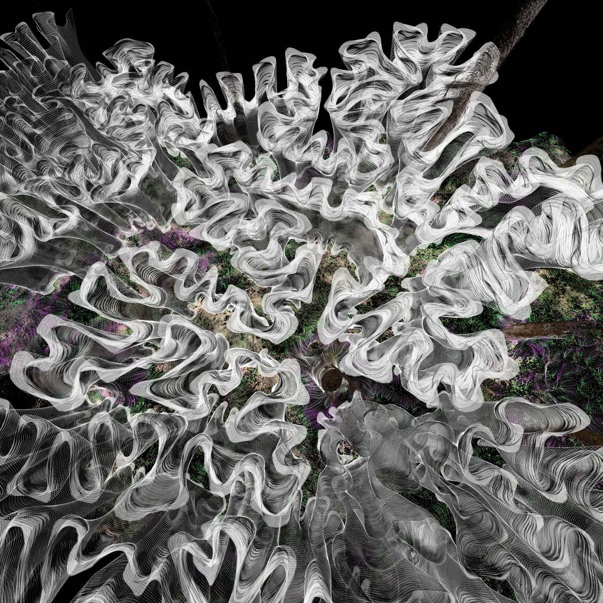
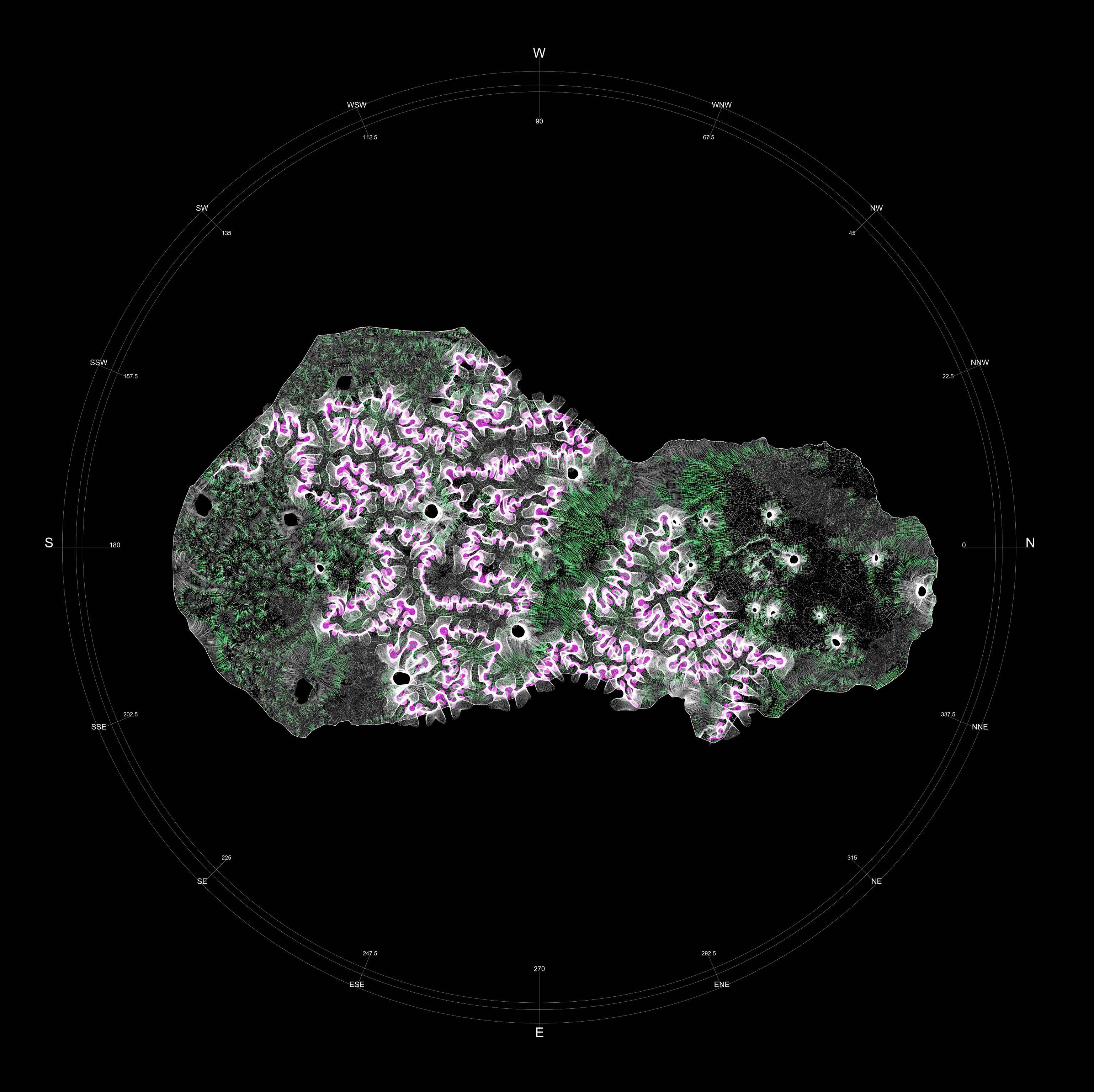
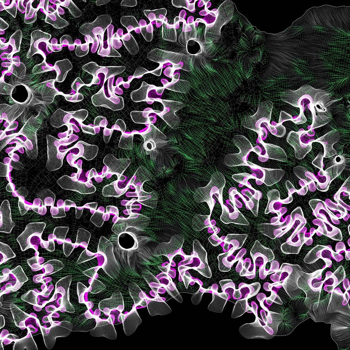
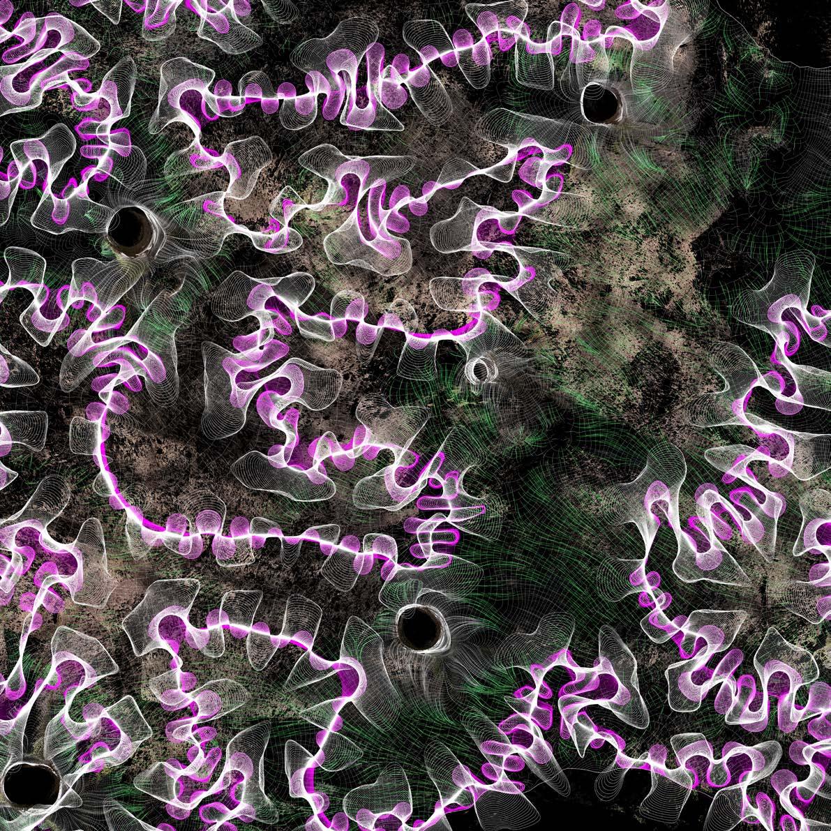
From page 48 through 51 I display the scanned forest using the produced point cloud under different environmental condition: the landscape is once covered with snow. The white surface and reflection, as deduced by the final point cloud density, complicates the scanning process, the result is better under normal condition. Afterwords, pages from 52 to 55, show the first elaboration of the data extracted from the point cloud.


Dense point cloud points: 99,987,435

Dense point cloud points: 67,991,455


Final point cloud points: 23,826,412
[RGB] point confidence filter Point cloud density: 100% value [R] domain: 0 to 255
[RGB] point confidence filter Point cloud density: 68% value [R] domain: 2 to 255
[RGB] point confidence filter
Point cloud density: 24% value [R] domain: 4 to 255