www.australianpipelinevalve.com.au INSTALLATION, OPERATION & MAINTENANCE MANUAL GATE VALVES FORGED API 602 ASME B16.34
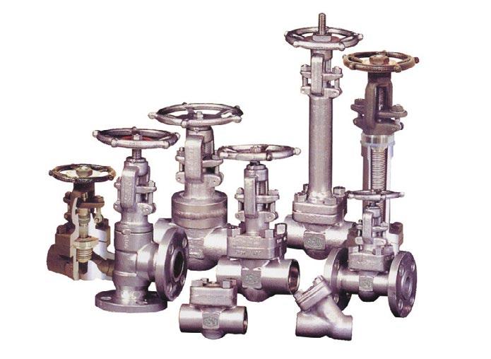
COMPLETE PRODUCT LINE
“Australian Pipeline Valve produces isolation, control and flow reversal protection products for severe and critical service media in utility, steam, pipelines, oil & gas and process industries. APV valves and pipeline products form the most competitive portfolio in the market.”
View our catalogues at www.australianpipelinevalve.com.au AUSTRALIAN PIPELINE VALVE BRAND RANGE - CATALOGUES APV FAMILY OF BRANDS RANGE - CATALOGUES
Oilfield Products Valves & Wellheads Gate, Globe & Check Valves - Forged Steel Plug Valves Lubricated, Sleeved & Lined Gate, Globe & Check Valves - Cast Steel Diamond Gear Gearboxes Flowturn Gate, Globe & Check Valves Flowturn Instrument Valves Flowturn Ball Valves Multiway & Deadman Flowturn Strainers & Sight Glasses Supercheck Wafer Check Valves Superseal Butterfly Valves Steamco Steam Valves Superseal Industrial Ball Valves TwinLok Tube Fittings Uniflo Check Valves
Actuators
Valves Floating & Trunnion Mounted Ball Valves Floating Small Bore Ball Valves Special Service Product Brochure Contact us for your local stockist/distributor
Torqturn
Ball
GATE VALVES - FORGED - API602/ASME B16.34 Australian Pipeline Valve - Installation, Operation and Maintenance Manual 1 Introduction 3 Safety Information 4-5 Valve Identification 6 1.0 Installation 7-11 1.1 Installation positions 7 1.2 Preparation for installation 7 1.3 End connections 7-11 1.4 Post-installation procedures 11 2.0 Operation 11 3.0 Maintenance 12-14 3.1 Removal of packing rings and use of backseat 12-14 3.2 Other repairs 14 4.0 Maintenance Procedures 15-16 4.1 Preventative maintenance and periodic inspection 15-16 5.0 Extraordinary Maintenance or Replacement/Repair of Damaged Parts 16-24 5.1 Stem 16 5.2 Gland disassembly & replacement of stem packing 16-19 5.3 Bonnet disassembly & stem replacement/repair 19-20 5.4 Bonnet reassembly 21 5.5 Disassembly of yoke nut 21 5.6 Disassembly of Valve - wedge/disc and seats 21-22 5.7 Wedge and disc repairs 22 5.8 Seat repairs - wedge gate and parallel slide valves 22-23 INDEX

GATE VALVES - FORGED - API602/ASME B16.34 Australian Pipeline Valve - Installation, Operation and Maintenance Manual 2 5.9 Reassembly & test 24 Appendix A - Bonnet bolting torque 25-26 Appendix B - Figure number system 27 Appendix C - Exploded B.O.M. 28-29 Appendix D - Working pressure & test matrix 30 Warranty 31 © Copyright Australian Pipeline Valve 1990 - 2024 Edition Catalogues, photos, brochures and technical publications are the exclusive property of Australian Pipeline Valve. Any unauthorised reproduction in total or in part, shall result in prosecution. Products and data sheets in this publication are subject to change at anytime without notice. Australian Pipeline Valve reserves the right to carry out amendments to products and materials.
INTRODUCTION
The majority of this information is common knowledge to experienced valve users. When properly installed in applications for which they were designed, Australian Pipeline Valve (APV) valves will give long reliable service. This instruction is only a guide for installation and operation on standard service and covers general maintenance and minor repairs. A professional APV approved valve engineering facility should be utilised for reconditioning or major repairs.
We recommend that this entire document be read prior to proceeding with any installation or repair. Australian Pipeline Valve and it’s parent company take no responsibility for damage or injury to people, property or equipment. It is the sole responsibility of the user to ensure only specially trained valve repair experts perform repairs under the supervision of a qualified supervisor.
RESPONSIBILITY FOR VALVE APPLICATION
The User is responsible for ordering the correct valves. The user is responsible for ensuring APV Valves are selected and installed in conformance with the current pressure rating and design temperature requirements. Prior to installation, the valves and nameplates should be checked for proper identification to ensure the valve is of the proper type, material and is of a suitable pressure class and temperature rating to satisfy the requirements of the service application.
Do not use any valve in applications where either the pressure or temperature is higher than the allowable working values. Also valves should not be used in service media if not compatible with the valve material of construction, as this will cause chemical attacks, leakage, valve failure.
RECEIVING INSPECTION AND HANDLING
Valves should be inspected upon receipt to ensure:
- Conformance with all purchase order requirements.
- Correct type, pressure class, size, body and trim materials and end connections.
- Any damage caused during shipping and handling to end connections, hand wheel or stem.
The User is advised that specifying an incorrect valve for the application may result in injuries or property damage. Selecting the correct valve type, rating, material and connections, in conformance with the required performance requirements is important for proper application and is the sole responsibility of the user.
GATE VALVES - FORGED - API602/ASME B16.34 Australian Pipeline Valve - Installation, Operation and Maintenance Manual 3
Note
SAFETY INFORMATION
The following general safety information should be taken in account in addition to the specific warnings and cautions specified in this manual. They are recommended precautions that must be understood and applied during operation and maintenance of the equipment covered in this I.O.M.
To avoid injury, never attempt disassembly while there are pressures either upstream or downstream. Even when replacing gaskets or packings, caution is necessary to avoid possible injury. Disassemble with caution in case all pressures are not relieved.
To prevent valve bending, damage, inefficient operation, or early maintenance problems, support piping on each side of the valve. Warning, certain gases and fluids could cause damage to human health, the environment or property hence the necessary safety elements to prevent risk should be taken.
• A valve is a pressurised mechanism containing fluids under pressure and consequently should be handled with appropriate care.
• Valve surface temperature may be dangerously too hot or too cold for skin contact.
• Upon disassembly, attention should be paid to the possibility of releasing dangerous and or ignitable accumulated fluids.
• Ensure adequate ventilation is available for service.
This manual provides instructions for storing, general servicing, installation and removal of gate valves. APV and it’s resellers refuse any liability for damage to people, property or plant as well as loss of production and loss of income under any circumstances but especially if caused by: Incorrect installation or utilisation of the valve or if the valve installed is not fit for intended purpose. It is the sole responsibility of the user to ensure the valve type and materials are correctly specified.
GATE VALVES - FORGED - API602/ASME B16.34 Australian Pipeline Valve - Installation, Operation and Maintenance Manual 4
DURING OPERATION TAKE INTO ACCOUNT THE FOLLOWING WARNINGS:
a- Graphite/Graphoil packing and body gaskets are very brittle, any impacting, twisting or bending should be avoided.
b- The valve’s internal parts such as disc, stem, seats, seals, gaskets shall be handled with care avoiding scratches or surface damage.
c- All tools and equipment for handling the internal parts shall be soft coated.
d- Valves can be fitted with gaskets or seals in PTFE, Buna, Viton, etc., hence high temperatures will damage sealing components.
e- Never part open or part close valve. Valve must be full open of full closed to avoid seat damage. For all operations make reference to position number on part list of the applicable drawing listed.
Packing leakage could result in personal injury. Valve packing is tightened prior to shipping but may require readjustments to meet specific service conditions.
Personal injury may result from sudden release of any process pressure. APV recommends the use of protective clothing, gloves and eyewear when performing any installation or maintenance.
Isolate the valve from the system and relieve pressure prior to performing maintenance.
Disconnect any operating line providing air pressure, control signals or electrical power to actuators.
Check the packing box for pressurised process fluids even after the valve has been removed from the pipeline, particularly when removing packing hardware or packing rings, or removing packing box pipe plug.
If a gasket seal is disturbed while removing or adjusting gasketed parts, APV recommends installing a new gasket while reassembling. A proper seal is required to ensure optimum operation.
GATE VALVES - FORGED - API602/ASME B16.34 Australian Pipeline Valve - Installation, Operation and Maintenance Manual 5
VALVE IDENTIFICATION
Each APV valve is identified with a nameplate, which is placed over the handwheel and secured with the hand wheel nut on gate and globe valves, and riveted to the cover on check valves. Below is an example.
When performing any work, ordering spare parts, or requesting technical support, please refer to this tag. The serial number, the part number and numbers on the side of the valve body are keys to proper valve identification.
GATE VALVES - FORGED - API602/ASME B16.34 Australian Pipeline Valve - Installation, Operation and Maintenance Manual 6
TYPE CLASS BODY ENDS SIZE STEM PKG DISC GASKET SEAT CWP@38ºC MAX TEMP API 602 ASME B16.34 9 10 11 12 13 14 15 8 8 7 6 5 4 3 2 1 No. Figure Number Code Description 1 Serial number Serial/batch numbers 2 Type The as-built valve type 3 Body Material Shell material (e.g. body, bonnet) 4 Stem Stem material (e.g. A105, WCB, F51, CF8M, etc.) 5 Disc Closure member base material + overlay 6 Seat Seat base material (+ overlay if applicable) 7 MAX Temp. Maximum temperature 8 Standard Applicable design codes 9 Model number APV valve figure number which delineates the as-built valve type, body, trim, features, packing, NACE, etc. Refer figure number system in Appendix B 10 Class Rated pressure class 11 Ends End connections 12 Size Nominal pipe size 13 PKG Stem packing (e.g. GRP, GRPF, PTFE) 14 Gasket Bonnet gasket (e.g. SW316, 316 ring, PTFE) 15 CWP @ 38ºC Cold working pressure temperature * NACE MR0175 Identifies corrosion resistance * NACE is indicated by a separate NACE tag.
1.0 INSTALLATION
Piping should be properly aligned and supported to reduce mechanical loading on the end connections.
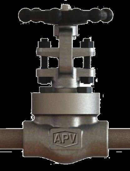
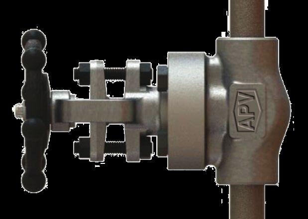
1.1 INSTALLATION POSITIONS
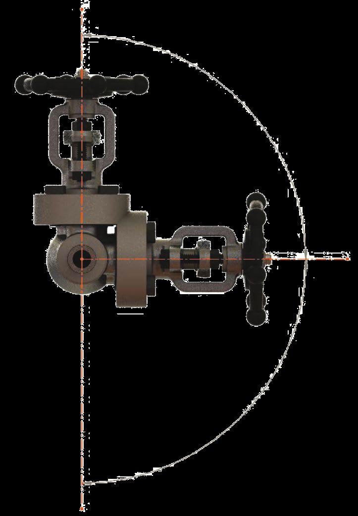
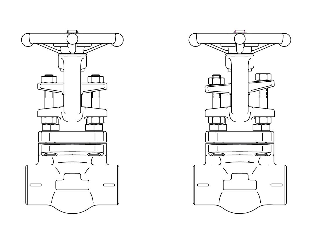
Gate valves are usually bi-directional, and therefore may be installed in either direction. In some cases, gate valves may be uni-directional, in which case the direction of flow will be indicated on the valve body. Gate valves should be installed with the stem in a vertical up position on horizontal lines. Other acceptable stem positions are at an angle between the vertical and horizontal axis which still allows for complete drainage. If installed with the stem below the horizontal axis, complete drainage is not possible and solids may accumulate in the valve bonnet, which will greatly affect the valve operation and service life. Gate valves may also potentially be installed in vertical lines but this must be specified at time of order so the valve can be as-built and tested for vertical service. See Figure 1 for details.
GATE VALVES - FORGED - API602/ASME B16.34 Australian Pipeline Valve - Installation, Operation and Maintenance Manual 7
FIGURE 1
VALVE POSITIONING
Horizontal Line
Maximum Rotation NotAcceptable
Vertical Line
1.2 PREPARATION FOR INSTALLATION
• Remove protective end caps or plugs and inspect valve ends for damage to threads, socket weld bores or flange faces.
• Thoroughly clean adjacent piping system to remove any foreign material that could cause damage to seating surfaces during valve operation.
• Verify that the space available for installation is adequate to allow the valve to be installed and to be operated.
Note
Ensure sufficient clearance for the stem in the full open position. Inadequate clearance for valves may add mechanical loading to the valve ends. Sufficient clearance should be allowed for threaded end valves to be ‘swung’ during installation.
1.3 END CONNECTIONS
1.3.1 Threaded Ends
Check condition of threads on mating pipe.
Apply joint compound to the male end of joint only. This will prevent compound from entering the valve flowpath.
1.3.2 Flanged Ends
Check to see that mating flanges are dimensionally compatible with the flanges on the valve body ensure sealing surfaces are free of debris.
Install the correct studs and nuts for the application and place the gasket between the flange facings.
Stud nuts should be tightened in an opposing criss-cross pattern in equal increments to ensure even gasket compression. Refer Appendix A, Figure 8.
1.3.3 Socket weld Ends
Remove all debris, grease, oil, paint, etc., from the pipe that is to be welded into the valve and from the valve end connections.
Insert the pipe into the valve end connection until it bottoms out in the socket weld bore. Withdraw the pipe 1/16” so that a gap remains between the pipe and the bottom of the socket weld bore to prevent cracks (ASME B16.11). Tack the pipe into the valve and complete the fillet weld.
GATE VALVES - FORGED - API602/ASME B16.34 Australian Pipeline Valve - Installation, Operation and Maintenance Manual 8
Gate valves under 65NB should be lightly closed to prevent damage to the seating surfaces and stem caused by thermal expansion during the weld process.
1.3.4 Buttweld End Valves
Clean the weld ends as necessary and weld into the line using an approved weld procedure. Make sure the pipe and valve body material given on the nameplate or valve body is compatible with the welding procedure. (Refer the compatibility cross reference chart at our website for equivalent pipe, valve & fittings grades).
1.3.5 Valve Installation by Welding
Unless the valve contains PTFE packing and/or gasket, leave valves assembled and in the lightly closed position during installation, welding and post-weld heat treatment. This will prevent the valve seat from floating or distorting during the process. After welding completion, open the valve and flush line to clean out any foreign matter.
Valves under 40mm (1 1/2”) containing PTFE packing and/or gasket must be dis-assembled for installation as the welding temperature can adversely affect the PTFE components. Remove the bonnet and bonnet gasket and match mark each component during dis-assembly for proper reassembly. If you do not disassemble valves it will be the responsibility of the operator to ensure valves are kept cool during welding and then post-weld testing of the valve should be performed. Larger size valves over 50mm NB (2”) are less likely to transmit heat to bonnet and stem packing during welding but still care should be taken.
The responsibility for welding of the valves into piping systems is that of those performing the welding. Refer to ASME B31.1, B31.3 etc. Written welding procedures covering all attributes of the process and materials to be welded shall be in accordance with Section IX of the ASME Boiler and Pressure Vessel Code and any additional requirements from the applicable piping code including any possible necessary localised post weld heat treatment depending on material specifications.
Subsequent to welding, clean and inspect the finished weld(s) and, if necessary, repair any defects using a qualified weld repair procedure. In addition, cycle the valve open-closed to check for proper operation, making sure no binding has occurred due to the weld heat.
Special trim options and body materials such as valves with PTFE packing/soft seat/special seals/ and gaskets that have maximum temperature limits less than the valve, may require special welding and heat treatment considerations which are not included herein.
GATE VALVES - FORGED - API602/ASME B16.34 Australian Pipeline Valve - Installation, Operation and Maintenance Manual 9
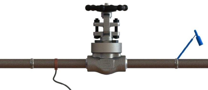
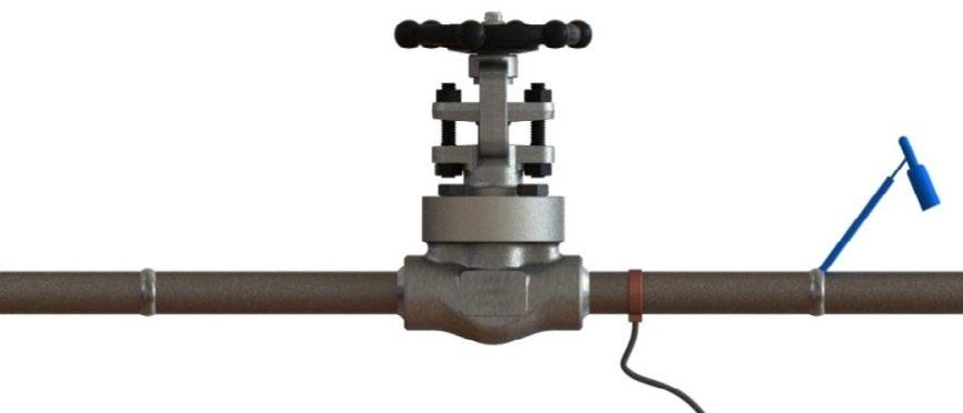
1.3.6 Post Weld Heat Treatment (PWHT)
The recommended method of PWHT is via local ceramic resistance heaters, individually monitored with thermocouples. Thermocouples are attached to the weld or welds. Properly sized ceramic heaters are wrapped around the weld area, extending approximately 6.35mm (1/4”) past the weld on the valve side. Do not wrap the valve body with a heating element. See Figure 1 for details. Wrap flexible insulation around valve ends, extending approximately 12.5mm (1/2”) past the valve on the valves side. It is not recommended to wrap the entire valve body with insulation. Prior to heat input close the valve completely, then open the valve approximately 1.58mm (1/16”) of a turn after the handwheel slack is run out. This very slight opening will allow the trim components to expand during the thermal cycle. Following PWHT, inspect the valve for smooth operation by cycling open and closed. If possible, perform a seat closure pressure test prior to service operation.
APV does not make any recommendations in regards to the actual PWHT details of temperature and time. This work is not within the scope of APV. APV recommends that all applicable “Piping Code” requirements be considered.
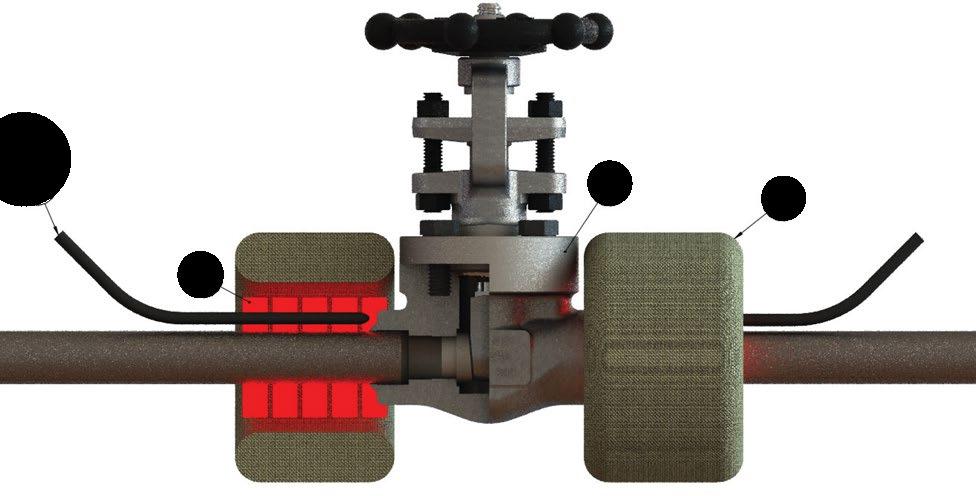
GATE VALVES - FORGED - API602/ASME B16.34 Australian Pipeline Valve - Installation, Operation and Maintenance Manual 10 FIGURE 2 INCORRECT Arcing can occur across close tolerance areas of valve due to ground strap location. Ground Strap Ground Strap Welding CORRECT Ground strap is positioned before the valve Welding WELD SET UP
4 3 2 1 ITEM DESCRIPTION 1 THERMOCOUPLE 2 VALVE 3 FIBRE INSULATION 4 CERAMIC HEATERS
FIGURE 3
POST WELD HEAT TREATMENT
For alloy steel valves or when welding specification or service conditions require field PWHT, the valve may be order with pipe nipples already welded and heat treated in the factory before valve assembly. The specified PWHT can then be performed in line without affecting the valve.
1.4 POST-INSTALLATION PROCEDURES
After installation, the line should be cleaned by flushing to remove any foreign material. When caustics are to be used to flush the line, additional flushing with clean water is required. The valve should be opened and closed after installation to ensure proper operating function.
With the line pressurised, check the valve end connections, body to bonnet/cover joints and stem packing area for leaks. The packing may have to be tightened to stop packing leakage.
2.0 OPERATION
Gate valves should only be used in the fully open or fully closed position. Gate valves are not designed for throttling.
Gate valves should not be left in the fully ‘back seated’ position under normal operating conditions. The packing may dry out under these conditions and leak as the valve is closed. However, depending on media, size, class and valve age many operators choose to leave the valve fully backseated at all times. Even when doing so there will still be some minor leakage past the back seat. Once the valve is brought into fully open position (back-seated), turn the hand wheel back one full turn.
Under no circumstances should the backseat be used to allow gland packing replacement or repair while the valve and system are pressurised.
A cool valve may leak through the gland when opened to hot fluid. Wait before tightening the packing as the problem may go away.
When the valve stops in closed position and is leaking do not try and force or cheat, instead try to back off the valve just a little and let the line pressure seal the valve. Forcing the valve further down will result in damage. The valve will seal on the downstream seat.
GATE VALVES - FORGED - API602/ASME B16.34 Australian Pipeline Valve - Installation, Operation and Maintenance Manual 11
3.0 MAINTENANCE
Proper safety equipment and apparel should be worn when preparing to service a valve. Observe the following general warnings:
Tools Required: - aside from standard wrenches (for bonnet cap screws and packing gland nuts) the only special tool needed for minor Australian Pipeline Valve valve maintenance is a packing hook.
Packing: - special care is to be placed in the tightening of the gland nuts during installation, to ensure the proper packing adjustment and functionality.
The packing gland should be checked periodically in service and tightened as necessary to stop leakage around the stem. Tighten in a manner to develop even loading on the gland. Tighten only enough to stop the leak.
3.1 REMOVAL OF PACKING RINGS AND USE OF BACKSEAT
See Section 5.2 for complete packing replacement instructions.
The backseat is not designed to be used to allow gland packing replacement or repair while the valve is pressurised. The primary reason for the back seating facility is to be used temporarily reduce leakage until the valve can be removed from the line to replace packing. One of the most common errors is to believe that if the Gate valve is back-seated (fully open position - and backseat sealing is made), this will help to prevent wear of the packing rings. Unfortunately using the back seat in this way over a longer period of time in some situations, could result in some serious issues:
a) Since the body, bonnet, stem and disc heat up and expand at different rates, experience shows that valve can get jammed/blocked in backseated position.
b) The gland packing will dry out since it’s not exposed to the media, and could immediately blow upon closing of the valve.
When placing a new valve into service, Australian Pipeline Valve recommends a preliminary packing adjustment to verify proper packing load. Additionally, it is recommended that a Baseline Leakage Test be performed following installation, but prior to start-up.
During the packing life cycle, normal and routine maintenance of the packing arrangement must be administered. Normal cycle life may require packing gland nut adjustments. Torque values vary depending upon valve type, class, design, bolting, material and size. Refer to the packing bolt torque chart in Appendix A Table B. Tighten the packing nuts clockwise to compress the packing. Do not over tighten or the valve will become too tight to turn (see 5.2.1). Fugitive emission stem packing can be fitted to reduce leakage rate to as low as 100 PPM for 1,500 cycles. Removal of old packing should be done by a valve maintenance professional, using a special flexible removal tool. The removal tools have special hooks, which screw into the packing ring. Removal of the packing ring is a difficult and time-consuming operation. Care has to be taken not to scratch the stem of the walls of the packing chamber during the removal of the packing rings.
GATE VALVES - FORGED - API602/ASME B16.34 Australian Pipeline Valve - Installation, Operation and Maintenance Manual 12
Over tightening will cause the packing to fail prematurely as well as increasing the force required to operate the valve. The packing gland flange should not bend even slightly, if it does you have over-tightened the valve and have to replace the flange.
If the leak cannot be stopped by tightening the gland nuts, it is necessary to add additional packing rings or completely repack the valve. Adding additional packing rings may damage the stem sealing system over a longer term. While Australian Pipeline Valve gate valves are equipped with a back seat feature, it is NOT ALLOWED TO REPACK THEM UNDER PRESSURE.
For normal operation in the open position, the stem should be backed off so that the backseat is not in contact. This permits the stem packing to assume it’s intended sealing function and not conceal unsatisfactory stem packing. In the event of stem packing leakage, the back seat can be used to stop stem leakage until circumstances permit a system shutdown and time for packing replacement. Stem packing replacement with the valve under pressure and backseated represents a hazard and should not be undertaken. The hazard is magnified as fluid pressure or temperature increases or when the fluid is toxic.
Back seating the valve and attempting to repack under pressure is hazardous and is not allowed under any circumstances. Rather than attempting to repack under pressure, it is preferable to use the backseat to control the stem leakage until shutdown of the line provides safe repacking conditions. Prior to replacing the packing rings, remove all pressure from the valve. If the backseat faces have been damaged by foreign material the backseat may leak into the packing chamber.
GATE VALVES - FORGED - API602/ASME B16.34 Australian Pipeline Valve - Installation, Operation and Maintenance Manual 13
FIGURE 4
RIGHT WRONG
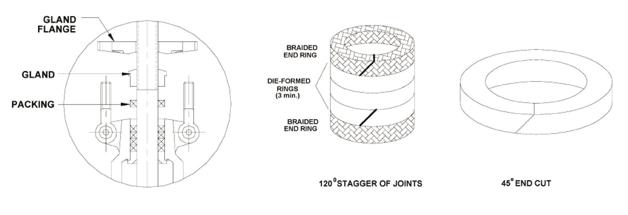
Australian Pipeline Valve graphite or PTFE and graphite packing sets are usually die formed and have no end cut. As a result, these rings cannot be replaced without removing the valve bonnet. If the valve is to be repacked without removing the bonnet, care must be taken when removing the original packing not to scratch the valve stem sealing surface. For fugitive emission service, proprietary fugitive emission packing must be used.
Note, PTFE has superior sealing properties compared to graphite, but is not firesafe and PTFE is only rated up to 180°C maximum, but PTFE pressure rating also down rates as temperature increases above 50°C.
Genuine APV die formed moulded low friction PTFE or graphite packing sets are recommended. A compatible ribbon packing system or equivalent braided packing stock may be used but the emissions will be higher. Also torque may increase. A corrosion inhibitor is recommended for stuffing box. The joints in the packing rings should be diagonally cut. When installing the rings, care should be taken to stagger the ring joints. If it is necessary to replace packing in-line, ensure the line pressure is totally isolated and no fluid remains, prior to attempting to repack valve in-line (refer Section 5.2). Wear anti-splash eye protection goggles.
Especially in the case of dangerous, hazardous, volatile, caustic or flammable liquids or gases, do not ever attempt to repack the valve in-line even if pressure has been isolated.
Other specialty packing such as V-ring Teflon Chevron sets will require that the valve be disassembled if repacking is required.
3.2 OTHER REPAIRS
Due to the relatively low replacement cost of small diameter standard carbon steel valves, it is usually less expensive to replace the complete valve than to have maintenance personnel carry out repairs. Additionally, in the case of gate valves, it must be removed from the line in order to replace or reface seat rings. Generally, the only justifiable repairs are replacement of packing and gaskets as previously described. However, see Sections 4.0 and 5.0 for further extraordinary maintenance and repairs. Always replace the bonnet gasket whenever a valve is disassembled. After removing valve from line, use adequate force to remove bonnet. Gasket seating surfaces should be scraped clean (avoid radial marks). Bonnet bolts should be tightened in a diagonal pattern at several different increasing torque settings until the final recommended torque value is attained. (See Tables A & B in Appendix A, including Figure 8.) ‘Pressure seal’ bonnets require a proprietary gasket, do not attempt to use non genuine gaskets.
GATE VALVES - FORGED - API602/ASME B16.34 Australian Pipeline Valve - Installation, Operation and Maintenance Manual 14
4.0
MAINTENANCE PROCEDURES
4.1 PREVENTATIVE MAINTENANCE AND PERIODIC INSPECTION
APV recommends that periodic inspections be carried out on all valves. The frequency of these inspections depends on the severity of the service and the frequency of the valve operation. As a minimum, all valves should be inspected quarterly to ensure proper operation and discourage the damage compounding effects of leakage. The following list details the areas requiring inspection and maintenance.
Items to Inspect
Check all lubrication points
Check body/bonnet join for leaks
Check for packing leaks
Check stem threads for wear
Ensure stem and seal areas are free from debris
If conditions permit, operate valve
Inspect all external connections
Inspect condition of actuator and/or gear operators (if applicable)
Inspect valve for obvious damage
Do not remove or loosen the packing gland or bonnet bolts while the valve is pressurised.
1. The valve stem packing should be inspected monthly. If the stem packing shows signs of leakage, simply tighten the adjusting nuts to compress the packing. Do not over tighten the adjusting nuts as this will make operation of the valve more difficult. If, after tightening the adjustment nuts to their fullest extent, the leakage does not stop, it is then necessary to replace the stem packing. It is not recommended that additional packing rings be added to the stuffing box as this may cause damage to the stem sealing system. For packing replacement see Sections 3.1 and 5.2.
2. Regular maintenance of the valve is required to assure smooth operation. Stem threads should be inspected and lubricated frequently to ensure ease of operation. APV valves are supplied with the stem threads engaging the yoke nut pre-greased. These components should be kept constantly lubricated by applying the grease directly on the stem when the valve is in the open position
GATE VALVES - FORGED - API602/ASME B16.34 Australian Pipeline Valve - Installation, Operation and Maintenance Manual 15
Lubrication Points GATE VALVE - TOP WORKS
FIGURE 5
or through the grease injector in the yoke nut when provided. Lubrication/greasing of the stem should be conducted every six months or more often as needed, based on the environment the valve is installed. Inspection should confirm that the valve is sealing properly. Stem packing should be inspected at least every six months to ensure zero leakage from the packing chamber. For water & oil service, regular maintenance should be scheduled every 3 months. For more corrosive mediums, inspection and maintenance should be completed once a month.
3. Bonnet bolt tension should be checked periodically when valves are used in high temperature applications where creep may occur. Although leaks through bonnet ring or spiral gaskets are rare, erosion or corrosion could cause bonnet seal to fail. In these cases, a new gasket is required. Refer Section 5.3 for replacing bonnet gasket. Refer Appendix A and Tables A & B, and Figure 8 for torque figures and tightening sequence.
4. With problematic service applications it is recommended that the valve be periodically at least partially stroked to ensure valve functions and to ensure there is no product deposits entering into seat or stem area which may render operating more difficult. Duration depends on service, criticality, etc. However, it also must be factored in that if there are impurities or particulates in the line which are likely to be built up in the seat area, each operation could reduce seat life proportionately.
5.0 EXTRAORDINARY MAINTENANCE
5.1 STEM
If the stem locks or “freezes”, causes can generally be attributed to dry worn packing or a dry yoke nut. In either of these cases, the following service is required:
a) Unscrew gland nuts, remove the gland flange and bushing to expose stem packing. Replace stem packing if it is damaged.
b) Check lubrication of yoke nut. If it is dry, remove the yoke nut and determine if there is evidence of seizure marks. If so replace it with a new yoke nut.
5.2 GLAND DISASSEMBLY & REPLACEMENT OF STEM PACKING
In those cases where the valve cannot be removed from the piping system, it is important that prior to servicing, the valve be opened to its fullest extent and the valve be purged of any pressure and fluid (protective goggles should be worn).
a) Partially unscrew gland packing nuts to reduce the compression load on the stuffing box. Remove the stem packing.
b) Lift the gland flange/follower and gland out of the stuffing box.
c) Remove old packing as per Section 3.1.
d) APV fugitive emission graphite and PTFE packing has solid seal ring that must be cut for removal. Any remains of existing packing must be removed from the stuffing box and stem.
GATE VALVES - FORGED - API602/ASME B16.34 Australian Pipeline Valve - Installation, Operation and Maintenance Manual 16
5.2.1 Stem Packing Replacement & Stem Repair
First remove the valve from the line. To prevent injury ensure that all fluid and pressure is removed from the valve both upstream and downstream before removal and disassembly. When removing drain or stem plug wear protective eye masks to avoid injury.
In the case of dangerous, hazardous, volatile, caustic or flammable liquids or gases, it is dangerous to attempt to repack the valve in-line even if pressure has been isolated. Never attempt any metal scraping, scratching or machining as this can cause imflammable liquids to ignite or cause personal chemical injury.
1. Check tightness of valve operation to serve as a reference when re-tightening. Remove gland nuts and the hook. Lift the gland up the stem clear away from the packing chamber.
2. Remove the defective packing rings with a sharp tool or packing hook. Do not scratch or score the machined surfaces of the stem or packing chamber.
3. Examine the machined surfaces of the stem and packing chamber. Remove any scratches, scoring or burrs with an emery cloth or by hand filing. Clean the stem with a solvent soaked rag. Scratches to the stem and the packing chamber no deeper than 0.25mm (0.010”) can be removed by polishing the surface with a buffing wheel. The surface finish of the packing chamber should be Ra 3.2µm and the stem should be Ra 0.5 ~ 0.8µm.
4. Count original number of rings and measure x-section thickness. If original packing cannot be counted or measured, follow the steps below:
a) Measure the stem diameter (OD), stuffing box diameter (ID) and stuffing box depth (d).
b) Packing x-section (R)=(ID - OD)/2
c) # rings = (1.25 x d)/R
5. Install new packing. Use a genuine APV low emission, low friction packing set. If using standard coils of packing material: cut each ring at a 45 degree angle and stagger the joints at 120 degrees, every fourth joint will be in the same position as the first. Install rings individually using a split ring spacer, compressing each ring by hand tightening + 1/4 turns on each packing gland nut.
6. Each ring should be firmly compressed into position before the next ring is added. Rings should fit snuggly ino the stuffing box; the ends of a packing ring must not overlap or remain open when fitted into the stuffing box.
7. When packing chamber becomes filled with packing, reassemble gland and gland flange. Alternate tightening packing gland flange nuts 1/4 turn at a time until eyebolts begin to get tight. (If gland travels more than the height of one packing ring into the packing chamber, insert one more ring and repeat step 6. until chamber is filled).
8. Install the gland and the gland flange/follower, install the gland studs and nuts. Bolting lubrication is highly recommended to achieve adequate packing load. Tighten the nuts a few turns at a time to maintain a straight and level gland flange.
GATE VALVES - FORGED - API602/ASME B16.34 Australian Pipeline Valve - Installation, Operation and Maintenance Manual 17
9. Compare valve operation to original tightness. If valve operation is considerably tighter than original operating tightness, back off 1/4 turn on each gland nut & recheck tightness. For belleville spring energised gland packing bolts, refer to spring manufacturers torques. Where proprietary packing sets are used such as (example only) APV-Enviroseal M600, Garlock EVSP 9000, Burgmann 6070 or Chesterton 1622 please consult packing manufacturer’s torques. The serialised as-built drawing will indicate the packing used, please refer to APV. Various packing types, materials, proprietary combinations and styles with and without spacers/lantern rings, etc, and torque limitations of some bolting materials, bonnet design variations, stuffing box and stem smoothness, means it is not possible to safely publish recommended torques for packing. In addition, higher pressure ratings will require higher torques especially if media types are hazardous or more leak searching prone such as gas.
Note
We recommend using graphite packing with inbuilt lubrication such as APVEnviroseal M600 fugitive emission packing as adding grease to the bore can attract particles that damage the packing and the grease could cause product contamination. For an assured seal the only solution is to machine the stem and stuffing box smoothness as shown in figure 6.
10. Several hours after a repacked valve has been returned to service, inspect the packing area to ensure full compression, tight bolting and no leakage. Should leakage occur, tighten gland nuts at 1/4 turn increments until leakage stops. Do not over tighten or valve will become difficult to turn. The gland flange should not bend at all, if it does loosen and replace the flange.
11. Actuate the valve through a minimum of three (3) complete cycles ending with the valve in the closed position. Verify the torque provided for the valve being re-packed.
*Example only, refer to as-built drawing
GATE VALVES - FORGED - API602/ASME B16.34 Australian Pipeline Valve - Installation, Operation and Maintenance Manual 18
FIGURE 6
BRAIDED END RING DIE-FORMED RINGS BRAIDED END RING 45º 1 2 5 4 3 ITEM DESCRIPTION 1 GLAND NUT 2 GLAND BOLT STUDS 3 GLAND FLANGE 4 PACKING GLAND 5 PACKING 120° STAGGER OF JOINTS* 45° END CUT* TYPICAL GATE VALVE (BOLTED BONNET DESIGN) STEM PACKING*
FIGURE 6A
The stem packing style will vary according to valve size, type and class as well as the stem packing material specified. Examples include combination sets, wire reinforced braided packing, PTFE Chevron moulded sets, live loaded sets.
5.3 BONNET DISASSEMBLY & STEM REPLACEMENT/REPAIR
Before disassembly:
1. Check that the line is in a complete shut down phase then remove the valve from the line.
2. Pre-order all necessary spare gland packings and jointing gaskets.
3. Open the valve slightly by turning the handwheel anti-clockwise and loosen the gland.
4. Put identification markings on valve body, bonnet, disc/wedge, yoke and actuator. This helps to avoid mismatching of parts at the time of re-assembly.
5. If the bolts and nuts are too tight, apply deep penetrating oil then unscrew.
Refer to Sections 5.3.1 & 5.3.2 for bonnet removal and gasket replacement.
To replace or repair the stem when the valve is completely disassembled for general maintenance follow this procedure:
• Open valve half way then remove bonnet bolts and nuts.
• Lift up the bonnet to remove wedge. The wedge has to be reassembled in the same position as originally assembled: take care not to rotate it 180°. The valve could leak through the seats if wedge is rotated.
• With the bonnet removed, unscrew the gland bolts then lift up gland flange exposing the stem packing.
• Remove stem packing above the lantern ring (if so required) and then turn the hand wheel to force the stem down.
• Remove the stem through the stuffing box.
Always be sure that the valve is de-pressurised and isolated prior to performing any maintenance work. Do not attempt to repair valve in-line if volatile, dangerous, hazardous or flammable service.
Welded bonnet valves can be repacked but otherwise are not repairable.
GATE VALVES - FORGED - API602/ASME B16.34 Australian Pipeline Valve - Installation, Operation and Maintenance Manual 19
Note
Note
5.3.1 Bolted Bonnet Removal & Gasket Replacement
Always replace the bonnet gasket whenever a valve is disassembled. Gasket sealing surface should be scraped clean (avoid radial marks).
1. Disassemble all cover bolts and nuts.
2. Lift up the bonnet, gently and evenly break the bonnet seal with a lever if required before lifting the bonnet off.
3. Clean gasket surface areas, replace gasket and refit bonnet as detailed below.
4. Re-assemble as per Section 5.4.
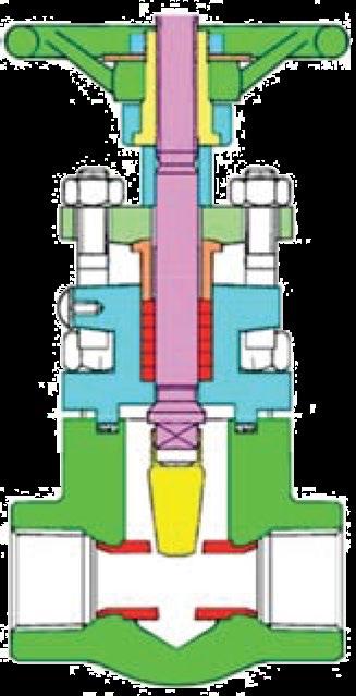
5.3.2 Pressure Seal Bonnet Removal & Gasket Replacement
In 900 to 2500 class a ‘pressure seal’ bonnet may be specified. The bonnet bolts or bonnet nut effect a seal on the pressure seal joint which forces the bonnet onto the gasket which in turn is forced up hard against the outer body. The higher the line pressure, the higher the sealing force against the gasket, further tightening the seal. Sometimes a ‘breech-lock’ threaded bonnet insert is used instead of a bolt energised bonnet, or a “uni-nut” system may be used. Refer to as-built drawing.
Flexible custom made gaskets are used, refer to as-built drawing. Live loading bonnet bolt springs may be fitted (refer to as-built drawing) which can be tightened to ensure a constant force is applied to the bonnet gasket. See sample drawing in Appendix C.
Only an experienced valve repair professional should attempt disassembly of pressure seal bonnet valves.
Note
There are different designs of pressure seal bonnet: - locknut type (breech lock), bonnet take-up type (bolted yoke arm) and the bolted style, hence, refer to as-built drawings. See Appendix C for for example.
The procedure to remove a pressure seal bonnet is as follows:
1. After disassembling the gland (refer Section 5.2) remove the bonnet bolts (or the threaded breechlock bonnet or uni-nut).
2. Remove the segmented gasket.
3. Clean the gasket area and always fit a new gasket before reassembly.
GATE VALVES - FORGED - API602/ASME B16.34 Australian Pipeline Valve - Installation, Operation and Maintenance Manual 20
5.4 BONNET REASSEMBLY
The procedure to reassemble the valve is as follows:
Re-insert the stem through the stuffing box taking special care to reassemble parts in sequence. If so equipped, avoid allowing the lantern ring to slide into the stuffing box. Next, insert the remaining packing rings into the stuffing box and compress using the gland and flange. Then, reassemble nuts and tighten.
Note, the stem must slide freely through the stuffing box without applying excessive force. Finally, install the bonnet gasket making sure it is not damaged. The gasket should be replaced if there is any question as to its performance (refer to Sections 5.3.1 & 5.3.2).
Raise the bonnet, making sure the stem is in the half open position, then connect disc to stem. Lower bonnet on to the valve body making sure that the disc fits exactly into body guides and the bonnet is properly seated. Align holes and tighten bonnet nuts taking care that excessive force is not used, to avoid damaging the gasket. Hydrostatically test the valve to ensure that there is no leakage.
5.5 DISASSEMBLY OF YOKE NUT
When necessary use the following procedure for disassembling and replacing yoke nut:
a) Direct hand operated valves (hand wheel)
• Remove set screw;
• Unscrew hand wheel nut;
• Remove hand wheel;
• Unscrew yoke but retaining nut, removing spot welds if necessary.
Reverse the procedure for reassembly.
5.6 DISASSEMBLY OF VALVE - WEDGE/DISC AND SEATS
An indication of valve leakage is a pressure loss in the high pressure line side after a valve has been properly closed. In the case of hot water or steam lines, note whether the downstream pipe remains hot beyond the usual length of time. This type of leak may be the result of a distorted seat caused by improper welding of the valve into the pipeline or seating damage caused by foreign particle matter or by stress relieving temperatures that may have been used during installation.
Leaks can also develop from failure to close the valve tightly, resulting in high-velocity flow through a small opening. Trim materials like CR13 (410SS) and especially hardfacing materials like Stellite 6 are corrosion and erosion-resistant, but grooves, pit marks or other surface irregularities may still form on the mating surfaces. Valves which leak should be repaired as quickly as possible to prevent greater damage caused by high velocity.
Leakage through seats and wedges/discs cannot be verified when valve is in service (unless a downstream drain is fitted). However, when leaks are identified, immediate action is necessary. Any delay can permanently damage the seat or wedge/disc seal surfaces. Never leave valve part open when in service as gate valves are not designed to throttle flow. Leaving valve part open will result in damage to wedge/disc and seats due to venturi action erosion.
GATE VALVES - FORGED - API602/ASME B16.34 Australian Pipeline Valve - Installation, Operation and Maintenance Manual 21
To repair or replace disc or seats, the valve must be removed from the line then first follow the same procedure in Section 5.3 and then:
• Make sure that the valve is not under pressure before unscrewing bonnet nuts.
• Remove bonnet, being careful not to damage the gasket.
• Remove bonnet when wedge/disc is in half open position.
• Lift up bonnet until wedge/disc is disconnected from guides.
• Release wedge/discs from stem.
If seat surfaces show signs of seizing, pitting, grooves or other defects not deeper than 0.8mm (1/32”) it is possible to repair seating surfaces to its original condition by relapping the surface with line grain abrasive paste, creating perfect tightness once again. Refer to 5.7, 5.8. Defects having a depth exceeding 0.8mm (1/32”) cannot be repaired by lapping, in this case, parts must be replaced or professionally reconditioned by an APV approved reconditioner.
It is recommended that the face of the disc be blue metal tested to check for contact of seating surface after final lapping. For re-assembly of valves use the procedure outlined under Sections 5.4 - 5.9. If valve is custom fitted with special soft seat inserts – consult APV.
Note, if the valve was ordered to a higher level of shut-off class, then the seating surfaces will have to be blue metal matched until the required shut-off is attained.
5.7 WEDGE AND DISC REPAIRS
a) After disassembling valve as described in 5.6, inspect the wedge or disc for scratches or damage.
b) If seating faces are scratched, the wedge or disc must be lapped. Slight pitting, grooving or indentions no deeper than 0.1mm (0.005”) can be removed by lapping. If defects cannot be corrected by lapping, wedge or disc should be ground or machined by an APV approved valve reconditioning professional.
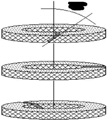
c) For the lapping, a flat plate, preferably cast iron, should be used and an abrasive lapping compound mixed with olive oil should be evenly distributed over the plate. Only light, even pressure should be applied to the plate, lifting the wedge or disc as often as possible to prevent accumulation of particles in one area and to follow for proper distribution of the lapping compound. The lapping plate should be turned slightly every few strokes to maintain a flat surface. The part should be lapped until seat faces are smooth. APV recommends the use of silicone carbide compound, medium coarse and fine grit compound for finishing.
d) Thoroughly clean off the lapping compound with a suitable cleaning fluid such as acetone or alcohol. Do not use solvents containing chloride or fluoride.
Note, If lapping cannot be performed the wedge or disc seating surface should be ground by a professional APV approved valve restorer.
5.8 SEAT REPAIRS – WEDGE GATE AND PARALLEL SLIDE VALVES
These valves are avilable with either threaded-in seat rings or an integral seat, both of which may be repaired (threaded in seats shall be replaced) whilse the valve is in line.
a) If seating faces are damaged, the body seat must be corrected by lapping. Slight pitting, scratches or
GATE VALVES - FORGED - API602/ASME B16.34 Australian Pipeline Valve - Installation, Operation and Maintenance Manual 22
indentations no deeper than 0.1mm (0.005”) can be removed by lapping. If defects cannot be corrected by lapping, the seats should be ground using specialised automatic grinding/lapping equipment.
Consult a professional valve repairer. Grind the seat using automatic grinding equipment can save considerable time.
b) Where seat faces can be repaired using a lapping plate, the plate should be made of cast iron if possible and should be large enough to cover the face of the seat. Apply lapping compound mixed with olive oil and distribute over the plate.
c) With a lapping compound in place, between the mating surfaces, the disc should be reciprocally rotated: the strokes should be light, and the disc should be lifted frequently and turned to a new position, circularly around the valve body, so the lapping will take place over a new area.
d) Continue lapping until all defects are removed; apply a final finish with a fine lapping compound.
5.9 REASSEMBLY & TEST
1. Re-assemble in reverse order of disassembly.
2. Bonnet bolts should be tightened in a diagonal pattern at several different increasing torque settings in accordance with the recommended torque value (see Tables A & B, Appendix A and Figure 8).
3. Test in accordance with API 598.
4. When performing a body test ensure the valve is in the open position but not in backseat position. Tighten gland packing only just enough to prevent leakage without needing to employ the backseat. In this way it can be proven the packing is performing it’s task. Over-tightening the packing gland will increase wear and tear of the packing and can damage the gland, gland bolts or stem. If the valve is tight to turn with ease, loosen the packing gland slightly. The backseating can also serve to determine if the valve stem or backseat itself is damaged by slightly loosening the packing gland nuts. Remember, compressed graphite packing rings will not initially be decompressed when the packing gland is loosened but they will leak. Always keep the valve in the backseat position when retightening the packing.
GATE VALVES - FORGED - API602/ASME B16.34 Australian Pipeline Valve - Installation, Operation and Maintenance Manual 23
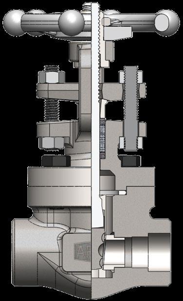
Typical Forged (up to 50NB) Bolted Bonnet Gate Valve Expanded View
1. Disc
Solid wedge is machined to the tightest tolerances to ensure trouble free shut off and cycling.
2. Stem
The stem is precision machined and inserts into the disc’s horizontal channel.
3. Gland Packing
The packing creates a seal above the back seat, between the bonnet and stem.
4. Packing Gland
Compresses the packing to create a stem seal above the back seat, between the bonnet and stem.
5. Packing Gland Flange
Applies pressure to the gland for accurate packing adjustments. (may be an integral part of gland)
6 & 13. Gland Bolts & Nuts
The gland bolt and nut allows for easy adjustments for packing compression.
7. Seats
Overlay, integral or separate swaged in seats are precision ground for optimal seating.
8. Body
Forged steel bodies provide low resistance flow and optimum strength and performance.
9. Gasket
The bonnet gasket creates a leakproof seal between the body and bonnet.
10. Bonnet & Yoke
Bonnet assemblies are built to the same standards as the bodies.
11. Bolts
The bonnet bolts secure the bonnet to the body.
12. Stuffing box
The stuffing box contains the packing.
14. Stem nut (yoke nut)
The stem nut provides a precision guide for proper stem alignment.
15. Hand wheel
The hand wheel cycles the valve
16. Hand wheel nut
The hand wheel nut secures the hand wheel to the bonnet assembly.
*Sample only, refer to as-built drawing as there are numerous designs for different sizes, classes, bonnet types & design standards.
VALVES - FORGED - API602/ASME B16.34 Australian Pipeline Valve - Installation, Operation and Maintenance Manual 24
GATE
16 15 14 13 12 11 10 9 8 7 1 2 6 3 4 5 6
7
FIGURE
APPENDIX A
Note:
(1) Torque tolerance -10%, + 12%.
(2) For temperatures above 750°F (400°C) use 75% of the torque values.
(3) Above torque values are with the bolts lubricated.
(4) Values above are based on 30,000 psi (206.85 Mpa) bolting stress and lubricated with heavy graphite and oil mixture or a copper based anti-seize grease.
(5) Do not exceed by more than 25% of values stated when emergency torquing is required.
(6) All bolts shall be torqued in the pattern as shown in Figure 8 on next page to ensure uniform gasket loading.
(7) Optimum torque can vary depending on type of body gasket but do not increase torque more than 10% above those shown.
(8) Consult us for other bolt material.
(9) Most B8M and B8 bolts are class 1 so do not assume class 2 unless you are sure. Note
For ‘pressure seal’ bonnet consult APV for torques (where bolting is applicable). Bolt tensions shown must be decreased by 25% when other or no lubrication used. Non lubricated bolts can have an efficiency of less than 50% the torque of values stated. Indicative torques are shown only, different body gasket systems, different sizes & classes, etc., will have different torque requirements. Furthermore, other stud grades can have much lower torques depending if class 1 or class 2 and or above variables.
GATE VALVES - FORGED - API602/ASME B16.34 Australian Pipeline Valve - Installation, Operation and Maintenance Manual 25
TABLE A INDICATIVE IDEAL BONNET BOLTING (BOLTED BONNET) TORQUE (NM) UNC STUD SIZE Bolting Material B7M/L7M B7/B16/L7 B8/B8M CL.1 B8/B8M CL.2 3/8 - 16 UNC 25 35 16 27 7/16 - 14 UNC 34 41 30 34 1/2 - 13 UNC 60 68 44 61 9/16 - 12 UNC 76 90 75 88 5/8 - 11 UNC 115 130 95 115 3/4 - 10 UNC 215 260 170 203 7/8 - 9 UNC 300 345 230 271 1 - 8 UNC 475 520 298 475 TABLE B INDICATIVE IDEAL BONNET BOLTING (BOLTED BONNET) TORQUE (NM) ISO Material M8 M10 M12 M14 M16 M20 Torque Values (Nm) Ideal Max. Ideal Max. Ideal Max. Ideal Max. Ideal Max. Ideal Max. B7 18 20 35 40 62 70 99 112 151 171 295 335 B7M 14 16 27 31 47 54 76 86 115 130 225 255 B8 CL.1 5 6 10 11 18 20 28 32 43 49 84 95 B8M 5 6 10 11 18 20 28 32 43 49 84 95 L7 18 20 35 40 62 70 99 112 151 171 295 335 L7M 14 16 27 31 47 54 76 86 115 130 225 255 B16 18 20 35 40 62 70 99 112 151 171 295 335
APPENDIX A - CONTD.
Examples only, refer to as-built drawing.
GATE VALVES - FORGED - API602/ASME B16.34 Australian Pipeline Valve - Installation, Operation and Maintenance Manual 26
FIGURE 8 BOLT TIGHTENING SEQUENCE 1 4 2 3 7 1 5 4 8 2 6 3
APPENDIX B
Figure Number System
B ASTM A105
C ASTM A182-F5
D ASTM A182-F9
E ASTM A182-F11
F ASTM A182-F22
G ASTM A182-F304
H ASTM A182-F304L
J ASTM A182-F316
K ASTM A182-F316L
GA GATE SOLID WEDGE
GF GATE FLEX WEDGE
GP GATE PARALLEL SLIDE
GL GLOBE
GS GLOBE SDNR (STOP CHECK)
GY Y-TYPE GLOBE (IN LINE)
YS Y-TYPE GLOBE SDNR
GN NEEDLE POINT GLOBE
PC PISTON (LIFT) CHECK
BC BALL CHECK
HC BALL HEAD PISTON (LIFT) CHECK
SC SWING CHECK
AG RIGHT ANGLE GLOBE
AY RIGHT ANGLE GLOBE Y-TYPE
ZZ SPECIAL
BB
WB
PS
BL
BELLOWS
See Section I
NP
BS
BW
RF
FF
UD
RJ RING
RU
ZZ
L ASTM A350-LF2
M ASTM A182-F304/F304L*
N ASTM A182-F316/316L*
P ASTM A182-F321
Q ASTM A182 F51
R ASTM A182 F55
S ASTM A182 F53
T ASTM A350-LF3
Z SPECIAL
*Dual Certified
G - NACE
Blank = NON NACE
N = NACE
R = STANDARD BORE
= FULL BORE
- = SPECIAL SUFFIX
I - SPECIAL
H - BORE BL = BELLOWS SEALED CR = CRYOGENIC
= EXTENDED BONNET
= LONG PATTERN
= C/W SPRING
PT = PTFE SEAT
ZZ = OTHER SPECIAL
J - BONNET GASKET
Blank Standard: SS Spiral + GRP (BB),
Pressure Seal Ring (PSB).
N/A- (WB)
1 SS Spiral + PTFE
2 S31803 Spiral
3 PTFE
4 SS Spiral + PTFE + GRP
5 Ring
9 Special
K - STEM PACKING
Blank Standard: Graphite.
N/A- (Check Valves)
L Graphite + PTFE
T PTFE
F Fugitive Emission GRP
P Fugitive Emission PTFE
Z Special
GATE VALVES - FORGED - API602/ASME B16.34 Australian Pipeline Valve - Installation, Operation and Maintenance Manual 27
(EXAMPLE)
BONNET,
F Trim Modifier G H Bore Nace - I Dash Special J K Bonnet Gasket Stem Packing A B C D E Type Class Connection Body Material Type F Trim
F
Z
A - TYPE
GLBBSW80ADR-5 : GLOBE VALVE, BOLTED
SOCKET WELDED, 800LBS, A105N, MONEL TRIM, NON NACE, STANDARD BORE, RING GASKET
= SPECIAL BORE
EX
LP
SP
F - TRIM CODES 15 ASME 150LBS 30 ASME 300LBS 60 ASME 600LBS 80 ASME 800LBS 90 ASME 900LBS 150 ASME 1500LBS 250 ASME 2500LBS 450 ASME 4500LBS 99 SPECIAL D - CLASS
DASH
NPT THREADED
NPT x SW
NS
BSP THREADED SW SOCKET WELDING
BUTT WELDING
RAISED FACE FLANGE
FLAT FACE FLANGE
FLANGE
UNDRILLED
FLANGE
JOINT
FLANGE
UNMACHINED
DRILLING RF/FF C - CONNECTION
SPECIAL
BOLTED BONNET
BONNET
WELDED
PRESSURE SEAL BONNET
SP
B - BONNET
BONNETLESS
SPECIAL
SEAL/CRYOGENIC/ EXTENDED BONNET
E - BODY
A ASTM A105N
BODY SEAT SURFACEDISC SURFACESTEM BACK SEAT TRIM CODE (1) B Bronze Bronze Bronze Bronze C AL-BronzeAL-BronzeAL-BronzeAL-Bronze D Monel(1) Monel(1) Monel Monel E F51(1) F51(1) F51 F51 G F55(1) F55(1) F55 F55 H Hastelloy B(1) Hastelloy B(1) Hastelloy BHastelloy B L F316(1)(6) F316(1)(6) F316(6) F316(6) M F316L(1) F316L(1) F316L F316L N Alloy 20(1) Alloy 20(1) Alloy 20Alloy 20 P F304(1) F304(1) F304 F304 Q F304L(1) F304L(1) F304L F304L R Alloy 625(1) Alloy 625(1) Alloy 625Alloy 625 V F53(1) F53(1) F53 F53 W F347(1) F347(1) F347 F347 Blank F6a/F6/410F6a/F6/410F6a/F6/410F6a/F6/410 Z Special(1) Special(1) Special Special MODIFIER EN ENP ENP (2) (2)(3) GE(5) Stellite #6Stellite #1217-4 PHStellite #6 I - - 17-4 PHM - - MonelT +PTFE Seat - -U Stellite Stellite (2) (2)(3) X (4) (4) (4) (4) XU Stellite (2) (2) (2)(3) Z - - Special(1) Add modifier below if applicable (2) As per trim code above. (3) Or Integral as per body. (4) API trim code# only. (5) Geothermal trim. (6) Can be dual certified 316/316L.
APPENDIX C
Exploded B.O.M. Welded Bonnet
(3) (4) (9) PHOSPHATED (6) (7) (7) - Psi
PHOSPHATED Psi 2175 15.0 Mpa
PHOSPHATED ºF -20 TO 800 Mpa
PHOSPHATED PHOSPHATED Psi 0.55
PLATED - PHOSPHATED BACKSEAT B16.34 BODY TEMPERATURE MEDIUM Water, Oil, Gas ºC -29 TO 425
ZINC PLATED TEST PRESSURE SHELL HYDRO SEAT HYDRO SEAT AIR
SEAT BONNET WELD INTEGRAL ASME 1 X V-PREP CONICAL (1) (2) Psi 20.5
- (2) (9) Mpa
(1) DYE PENETRANT TESTED (2) THREADED BONNET + FULL V-PREP WELD (3) PACKING CHAMBER BORE Ra ≤ 3.2 µ m TO API 602. BOTTOM MACHINED FLAT (4) DIE FORMED INTEGRAL PACKING RINGS (5) STEM SMOOTHNESS Ra ≤ 0.8˜ µ m (6) STELLITE: MINIMUM THICKNESS 1.0MM, STELLITE HARDNESS 36
45 HRC (331
18 Mpa
427 HB) (7) DISC & SEAT MINIMUM SMOOTHNESS Ra .4
.6 µ m (8) ROTATING STEM NUT. CORROSION RESISTANT & ANTI-GALLING. STEM & STEM NUT PRECISION ACME THREADS BURNISHED FINISH. SERVICEABLE IN LINE (9) BODY & BONNET FORGINGS AND JOINT ARE PRECISION MACHINED
& MFG. 2975 15.0
(5) 80
& INSPECTION A
CL 800 API 602/ISO 15761, ASME B16.34 ASME B16.34 API 602/ISO 15761 10.5
DIMENSION TEST d
CONNECTION 2175 Inch DN
OTHER REQ. PORT SIZE TRIM NOTES OTHER 15
Example only, refer to as-built drawing.
21.8
27.1
13.7
100 20
33.8
17.0
100 25
48.7
29.0
125 40
H 161 163 196 251 290
B1 9.6 12.7 12.7 12.7 16.0
61.2
180 Weight 1.8 2.2 4.1 6.5 9.8 L 79 92 111 120 140
160 50
MARKING W 1/2” 3/4” 1” 1 1/2” 2”
36.5
VALVES - FORGED - API602/ASME B16.34 Australian Pipeline Valve - Installation, Operation and Maintenance Manual 28
GATE
API 607-7th Edition Firesafe Certi ed 1 2 3 4 5 6 7 8 9 10 11 12 13 14 15 16 17 W A H (OPEN) 5 +L 1.6 +SW B1 18 d Dimensions in millimeters Wedge Gate Valve, Welded Bonnet, Model GAWBSW80AXUNR NPS 1/2”~2” (DN15~DN50) Class 800 SW, HWOP, SB, A105N, Trim API #8 ORDER N O / DWG N O REV. APPROVED CHECKED DRAWN 412 00 DIMENSIONS (MM) & WEIGHT (KG) APV DWG FRM 412 Australian Pipeline Valve B.T. S.Q. C.C. BILL OF MATERIALS NO. PART NAME MATERIAL NOTES 1 2 3 4 5 6 7 8 9 10 11 12 13 14 15 16 BODY SEAT DISC STEM BONNET PACKING PIN GLAND GLAND EYEBOLT GLAND FLANGE NUT STEM NUT NUT NAME PLATE HAND WHEEL WASHER ASTM A105N ASTM A276 410+ST#6 ASTM A276 420 ASTM A182 F6A ASTM A105N FLEXIBLE GRAPHITE ASTM A276 410 ASTM A276 410 ASTM A193 B7 ASTM A105N ASTM A194 2H ASTM A276 410 AISI 1035 SS304 ASTM A197 A3 (8)
ZINC
17
BACK
RATING DESIGN
PRESS-TEMP RATING FACE TO FACE DIM. END
END
www.australianpipelinevalve.com.au SW ASME B16.11 API 598/ISO 5208 MSS SP-25 PHOSPHATING PHO-WFGGC STANDARD BORE API #8 OPTIONAL HP SEAT TEST PERFORMED TO API 598 NACE MR-01-75 & MR-01-03 (ISO 15156)
APPENDIX C - CONT.
Exploded B.O.M. Pressure Seal Bonnet
PHOSPHATED PHOSPHATED PHOSPHATED - - (1)(2) CHESTERTON 1622 F.E. - (3) (7) PHOSPHATED - - (7) PHOSPHATED (4) (5) (4) (5) -
CL3
A182 F22
AISI 1035 ASTM A197 A3
19 NUT
18
DESIGN & MFG.
RATING
TO
Example only, refer to as-built drawing.
GATE VALVES - FORGED - API602/ASME B16.34 Australian Pipeline Valve - Installation, Operation and Maintenance Manual 29
API 607-7th Edition Firesafe Certi ed SCHEDULE NO: XXS I I 1 2 3 4 5 6 7 8 9 11 12 13 14 15 16 17 18 19 20 A 1.6 45° 30° 37.5° 1.5 B W H (OPEN) 5 +L 1.6 +9 d 21 Dimensions in millimeters Wedge Gate Valve, PSB, Model GAPSBW250FUR NPS 1/2”~2” (DN15~DN50) Class 2500 BW, HWOP, SB, A182 F22 Trim API #5 ORDER N O / DWG N O REV. APPROVED CHECKED DRAWN 406 00 DIMENSIONS (MM) & WEIGHT (KG) Inch DN L d A B H W 1/2” 3/4” 1” 1 1/2” 2” 15 186 10.5 21.3 6.4 321 200 20 186 13.5 26.7 7.8 321 200 25 186 17.0 33.4 9.1 360 200 40 216 29.0 48.3 10.2 406 280 50 279 37.0 60.3 11.1 490 300 APV DWG FRM 406 Australian Pipeline Valve B.T. S.Q. C.C. BILL OF MATERIALS NO. PART NAME MATERIAL NOTES 1 2 3 4 5 6 7 8 9 11 12 13 14 15 16 BODY SEAT DISC STEM P.S. INSERT/SEAL P.S. GASKET P.S SEGMENT RING BONNET PACKING (SET) PIN GLAND EYEBOLT NUT YOKE NUT GLAND
Weight 12.4 12.6 19.8 28.0 60.0 RATING
PRESS-TEMP
www.australianpipelinevalve.com.au FACE
GLAND FLANGE FACE
ASTM PORT SIZE TRIM NOTES OTHER CL 2500 API 602/ISO 15761 ASME B16.34 API 602/ISO 15761 BW ANSI B16.25 API 598/ISO 5208 MSS SP-25 PHOSPHATING PHO-WFGGC STANDARD BORE API #5 OPTIONAL API 598 LP SEAT TEST ALSO PERFORMED TEST PRESSURE SHELL HYDRO SEAT HYDRO SEAT AIR BACKSEAT B16.34 BODY TEMPERATURE MEDIUM Water, Oil, Gas ºC -29 TO 575 ºF -20 TO 1067 Mpa Psi 0.55 80 Mpa Psi 6875 47.4 Mpa Psi Mpa Psi 64.6 9375 47.4 6875 (1) PACKING CHAMBER BORE Ra ≤ 3.2 µ m AS PER API 602. BOTTOM MACHINED FLAT (2) DIE FORMED SET INCONEL WIRE REINFORCED EXFOLIATED GRAPHITE PACKING CHESTERTON 1622 (LOW FRICTION) FUGITIVE EMISSION CERTIFIED ISO 15848-1/API 622/API 624 & API 607 FIRESAFE CERTIFIED, CHEVRON TEXACO CERTIFIED C/W CORROSION INHIBITOR. NON HARDENING & WILL NOT SHRINK OR ABSORB MOISTURE (3) STEM SMOOTHNESS Ra 0.8˜ µ m (4) STELLITE: MINIMUM THICKNESS 1.0MM AS PER API 602, STELLITE HARDNESS 36 45 HRC (331 427 HB) (5) DISC & SEAT MINIMUM SMOOTHNESS Ra .4 .6 µ m (6) ROTATING STEM NUT. CORROSION RESISTANT & ANTI-GALLING. STEM & STEM NUT PRECISION ACME THREADS BURNISHED FINISH. SERVICEABLE IN LINE (7) BODY & BONNET FORGINGS AND JOINT ARE PRECISION MACHINED 20 BACK SEAT INTEGRAL CONICAL t 7.5 11.0 15.2 27.9 38.2 21 STEM NUT ASTM A276 410 (6)
ASTM A276 410+ST#6 ASTM A276 420+ST#6 ASTM A182 F6a ASTM A276 304 ASTM A276 304 ASTM A276 304 ASTM A182 F22 GRAPHITE+INCONEL WIRE ASTM A276 410 ASTM A193 B16 ASTM A194 4 ASTM A276 410 ASTM A276 410 ASTM A182 F22
17
HAND WHEEL WASHER
ZINC PLATED ZINC PLATED PHOSPHATED
DIM. END CONNECTION END DIMENSION TEST & INSPECTION MARKING OTHER REQ.
APPENDIX
D
WORKING PRESSURE & TEST MATRIX
CF8M/CF8/CF8C/CF3/CF3A/316/304/
F5, F5a, F11, F22, F51, F53, F55, C5 CE8MN, 4A, 5A, 6A, CD3MN (1.3/1.17/2.8)
CWP shown as per ASME B16.34-2017.
Test duration can be as per API598 (ISO 5208) or API6D (ISO 14313)
VALVES - FORGED - API602/ASME B16.34 Australian Pipeline Valve - Installation, Operation and Maintenance Manual 30
GATE
WCB/A105/LF2/LF3 (1.1) WC6/WC9/F5/F11/F22 (1.7/1.9/1.10) CLASS # CWP PSI BODY TEST X 1.5 PSI SEAT TEST X 1.1 PSI CWP MPA BODY TEST X 1.5 MPA SEAT TEST X 1.1 MPA CWP PSI BODY TEST X 1.5 PSI SEAT TEST X 1.1 PSI CWP MPA BODY TEST X 1.5 MPA SEAT TEST X 1.1 MPA 150 285 427.50 313.50 1.96 2.95 2.16 290 435.00 319.00 2.00 3.00 2.20 300 740 1110.00 814.00 5.10 7.65 5.61 750 1125.00 825.00 5.17 7.75 5.68 600 1480 2220.00 1628.00 10.20 15.30 11.22 1500 2250.00 1650.00 10.34 15.50 11.37 800 1975 2962.50 2172.50 13.61 20.41 14.97 2000 3000.00 2200.00 13.78 20.67 15.16 900 2220 3330.00 2442.00 15.30 22.94 16.83 2250 3375.00 2475.00 15.50 23.25 17.05 1500 3705 5557.50 4075.50 25.53 38.29 28.08 3750 5625.00 4125.00 25.84 38.76 28.42 2500 6170 9255.00 6787.00 42.51 63.77 46.76 6250 9375.00 6875.00 43.06 64.59 47.37
317/347 (2.1/2.2/2.5) 316L/304L/CN7M(Alloy 20)/M35-1/ M35-2/CF3/CF3M (2.3/3.4/3.17) CLASS # CWP PSI BODY TEST X 1.5 PSI SEAT TEST X 1.1 PSI CWP MPA BODY TEST X 1.5 MPA SEAT TEST X 1.1 MPA CWP PSI BODY TEST X 1.5 PSI SEAT TEST X 1.1 PSI CWP MPA BODY TEST X 1.5 MPA SEAT TEST X 1.1 MPA 150 275 412.50 302.50 1.89 2.84 2.08 230 345.00 253.00 1.58 2.38 1.74 300 720 1080.00 792.00 4.96 7.44 5.46 600 900.00 660.00 4.13 6.20 4.55 600 1440 2160.00 1584.00 9.92 14.88 10.91 1200 1800.00 1320.00 8.27 12.40 9.09 800 1920 2880.00 2112.00 13.23 19.84 14.55 1600 2400.00 1760.00 11.02 16.54 12.13 900 2160 3240.00 2376.00 14.88 22.32 16.37 1800 2700.00 1980.00 12.40 18.60 13.64 1500 3600 5400.00 3960.00 24.80 37.21 27.28 3000 4500.00 3300.00 20.67 31.01 22.74 2500 6000 9000.00 6600.00 41.34 62.01 45.47 5000 7500.00 5500.00 34.45 51.68 37.90
CLASS # CWP PSI BODY TEST X 1.5 PSI SEAT TEST X 1.1 PSI CWP MPA BODY TEST X 1.5 MPA SEAT TEST X 1.1 MPA 150 290 435.00 319.00 2.00 3.00 2.20 300 750 1125.00 825.00 5.17 7.75 5.68 600 1500 2250.00 1650.00 10.34 15.50 11.37 800 2000 3000.00 2200.00 13.78 20.67 15.16 900 2250 3375.00 2475.00 15.50 23.25 17.05 1500 3750 5625.00 4125.00 25.84 38.76 28.42 2500 6250 9375.00 6875.00 43.06 64.59 47.37 AIR TEST 80 PSI 0.55
MPA
WARRANTY
1. LIMITED WARRANTY: Subject to the limitations expressed herein, Seller warrants that products manufactured by Seller shall be free from defects in design, material and workmanship under normal use for a period of one (1) year from installation but in no case shall the warranty period extend longer than eighteen months from the date of sale. This warranty is void for any damage caused by misuse, abuse, neglect, acts of God, or improper installation. For the purpose of this section, “Normal Use”
means in strict accordance with the installation, operation and maintenance manual. The warranty for all other products is provided by the original equipment manufacturer.
2. REMEDIES: Seller shall repair or replace, at its option, any non-conforming or otherwise defective product, upon receipt of notice from Buyer during the Manufacturer’s warranty period at no additional charge. SELLER HEREBY DISCLAIMS ALL OTHER EXPRESSED OR IMPLIED WARRANTIES, INCLUDING, WITHOUT LIMITATION, ALL IMPLIED WARRANTIES OF MERCHANTABILITY AND FITNESS OR FITNESS FOR A PARTICULAR PURPOSE.
3. LIMITATION OF LIABILITY: UNDER NO CIRCUMSTANCES SHALL EITHER PARTY BE LIABLE TO THE OTHER FOR INCIDENTAL, PUNITIVE, SPECIAL OR CONSEQUENTIAL DAMAGES OF ANY KIND.BUYER HEREBY ACKNOWLEDGES AND AGREES THAT UNDER NO CIRCUMSTANCES, AND IN NO EVENT, SHALL SELLER’S LIABILITY, IF ANY, EXCEED
THE NET SALES PRICE OF THE DEFECTIVE PRODUCT(S) PURCHASED DURING THE PREVIOUS CONTRACT YEAR.
4. LABOR ALLOWANCE: Seller makes NO ADDITIONAL ALLOWANCE FOR THE LABOR OR EXPENSE OFREPAIRING OR REPLACING DEFECTIVE PRODUCTS OR WORKMANSHIP OR DAMAGE RESULTING FROM THE SAME.
5. RECOMMENDATIONS BY SELLER: Seller may assist Buyer in selection decisions by providing information regarding products that it manufacturers and those manufactured by others. However, Buyer acknowledges that Buyer ultimately chooses the product’s suitability for its particular use, as normally signified by the signature of Buyer’s technical representative. Any recommendations made by Seller concerning the use, design, application or operation of the products shall not be construed as representations or warranties, expressed or implied. Failure by Seller to make recommendations or give advice to Buyer shall not impose any liability upon Seller.
6. EXCUSED PERFORMANCE: Seller will make a good faith effort to complete delivery of the products as indicated by Seller in writing, but Seller assumes no responsibility or liability and will accept no back-charge for loss or damage due to delay or inability to deliver, caused by acts of God, war, labor difficulties, accidents, inability to obtain materials, delays of carriers, contractors or suppliers or any other causes of any kind whatever beyond the control of Seller. Under no circumstances shall Seller be liable for any special, consequential, incidental, or indirect damages, losses, or expense (whether or not based on negligence) arising directly or indirectly from delays or failure to give notice of delay.
GATE VALVES - FORGED - API602/ASME B16.34 Australian Pipeline Valve - Installation, Operation and Maintenance Manual 31

www.australianpipelinevalve.com.au AUSTRALIAN PIPELINE VALVE® HEAD OFFICE 70-78 Stanbel Road Salisbury Plain South Australia 5109 Telephone +61 (0)8 8285 0033 email: admin@australianpipelinevalve.com.au If you have any requirements in the field of valves, please contact us for a prompt response. Continuous development of Australian Pipeline Valve products may necessitate changes in the design or manufacture process. Australian Pipeline Valve reserves the right to effect any such changes without prior notice. © Australian Pipeline Valve 1990 - 2024 Edition LOCAL DISTRIBUTOR/AGENT IOM APV Gate Forged
