
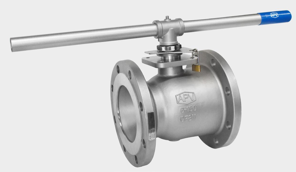
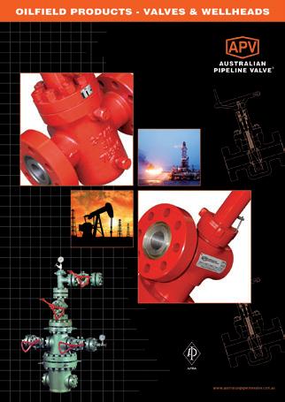
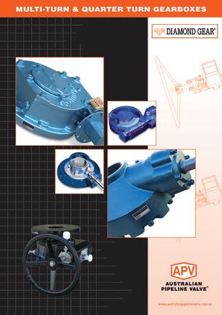
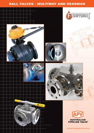
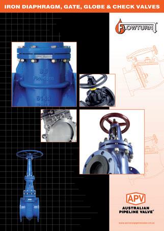
COMPLETE PRODUCT LINE
“Australian Pipeline Valve produces isolation, control and flow reversal protection products for severe and critical service media in utility, steam, pipelines, oil & gas and process industries. APV valves and pipeline products form the most competitive portfolio in the market.”
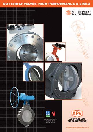
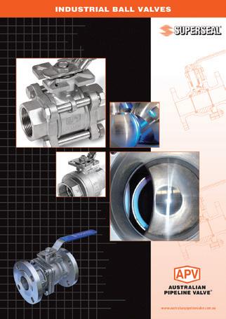
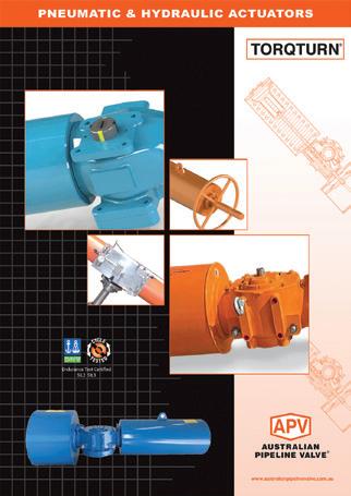
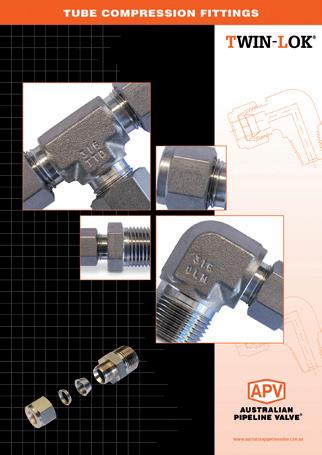
APV FAMILY OF BRANDS RANGE - CATALOGUES

INTRODUCTION
The majority of this information is common knowledge to experienced valve users. When properly installed in applications for which they were designed, Australian Pipeline Valve (APV) valves will give long reliable service. This instruction is only a guide for installation and operation on standard service and covers general maintenance and minor repairs. A professional APV approved valve engineering facility should be utilised for reconditioning or major repairs.
Note
We recommend that this entire document be read prior to proceeding with any installation or repair. Australian Pipeline Valve and it’s parent company take no responsibility for damage or injury to people, property or equipment. It is the sole responsibility of the user to ensure only specially trained valve repair experts perform repairs under the supervision of a qualified supervisor.
RESPONSIBILITY FOR VALVE APPLICATION
The User is responsible for ordering the correct valves. The user is responsible for ensuring APV Valves are selected and installed in conformance with the current pressure rating and design temperature requirements. Prior to installation, the valves and nameplates should be checked for proper identification to ensure the valve is of the proper type, material and is of a suitable pressure class and temperature rating to satisfy the requirements of the service application.
Do not use valves in applications where either the pressure or temperature is higher than the allowable working values. Also valves should not be used in service media if not compatible with the valve material of construction, as this will cause chemical attacks, leakage, valve failure.
RECEIVING INSPECTION AND HANDLING
Valves should be inspected upon receipt to ensure:
- Conformance with all purchase order requirements.
- Correct type, pressure class, size, body and trim materials and end connections.
- Any damage caused during shipping and handling to end connections, hand wheel or stem.
The User is advised that specifying an incorrect valve for the application may result in injuries or property damage. Selecting the correct valve type, rating, material and connections, in conformance with the required performance requirements is important for proper application and is the sole responsibility of the user.
CONSIDERATIONS OF TECHNICAL RISK/ LIMIT OF LIABILITY TO CLIENT FOR BALL VALVES
Australian Pipeline Valve don’t consider in our design the following factors of risk:
1. Australian Pipeline Valve ‘Standard’ ball valves can be used in a temperature range between -28.8 to +200°C. (Note, pressure limitations apply above 38°C refer to Pressure/Temperature charts.) For service temperatures below -28.8°C ball valve construction materials shall be submitted to an impact test at the minimum service temperature. For temperatures outside of the range of -28.8°C to +200°C ball valves have to be provided with seats, seals and body material able to withstand the temperature degree required.
2. The onus is on the customer to specify all materials of construction and service conditions. Australian Pipeline Valve shall assume standard materials and conditions if not otherwise specified.
3. Australian Pipeline Valve ‘Standard’ ball valves are not equipped with devices suitable to avoid internal over-pressures caused by incorrect operations of process or by-fluids & liquids subjected to an increase of volume and/or pressure (these devices, such as the over-pressure hole in the ball or safety seats are available upon request).
4. Australian Pipeline Valve ‘Standard’ ball valves are not designed with special devices to withstand a sudden thermal jump (thermal shock).
5. In general Australian Pipeline Valve ‘Standard’ ball valves are not mechanically designed to bear overloads due to exceptional atmospheric or natural phenomenon’s (such as earthquakes).
6. In general Australian Pipeline Valve ‘Standard’ ball valves are not designed to bear loads on flanges, on pipe connections or pipeline.
7. In general Australian Pipeline Valve ‘Standard’ ball valves can’t withstand ice inside their bodies (in this case user must specify the optional stem extension for insulating, avoiding the presence of residual product inside the valve).
8. Australian Pipeline Valve ‘Standard’ ball valves are not suitable for low temperature service below -29°C (-20°F) unless provided with cryogenic stem extension and other modifications (available on request).
9. Australian Pipeline Valve ‘Standard’ ball valves are suitable for ‘industrial’ oxygen (not medical) service when supplied degreased and packed in polyethylene bags only.
10. The compatibility between ball valves construction materials and medium is selected by the user. The user is ultimately responsible for verifying the compatibility between medium and materials.
11. Abrasive or dirty service, high temperature service, low temperature service, vacuum service, near zero pressure service and other special applications should be clearly stated when requesting quotation.
12. Floating valves without supplementary upstream relief hole in ball cannot be used for unstable fluids which, if trapped in the body cavity (valves in closed position) can be subject to the risk of increasing of pressure due to the increasing of temperature. If required, the purchaser must specify an upstream relief hole.
13. Valves without fugitive emission extensions cannot be used for toxic or dangerous medium with the risk of dispersion in the environment.
14. For fluids like oxygen, hydrogen or chlorine where the contact with oil or grease can create explosions valves that have not been properly cleaned, degreased and sealed in suitable boxes cannot be used. Avoid any kind of contamination until the moment of use. The same precautions have to be applied to valves for cryogenic services.
BALL VALVE START-UP
Before installing the ball valve onto the pipe-line it is mandatory for the user to verify the compatibility of the ball valve with service conditions (medium, temperature and pressure). With reference to standard ball valves held in stock the reseller and end user will have to assure themselves of the compatibility with the use of conditions required by the customer. Australian Pipeline Valve ball valves must be only used for on-off (fully open/fully closed) service.
Before using the ball valve in a potential explosive atmosphere it’s necessary: -
• To verify the compatibility between the ball valve and the zone in which the ball valve should be installed.
• To foresee the pipe-line ground condition on which the ball valve should be installed.
• To check that the temperature of the ball valve surface is not higher than the flammable point of the atmosphere in which the ball valve is installed (in this case specify an insulating cover device for the valve and an extension for the wrench)
• Before installing ball valves with welding ends to make sure that the process of welding is carried out in accordance with all the safety requirements of the classified zone.
• To avoid mechanical knocks during the installation that may cause sparks.
Australian Pipeline Valve cannot be held responsible for damage caused by use of the product especially if it is improper use or modified.
SAFETY INFORMATION
The following general safety information should be taken in account in addition to the specific warnings and cautions specified in this manual. They are recommended precautions that must be understood and applied during operation and maintenance of the equipment covered in this I.O.M.
Never attempt to disassemble a valve while there is pressure in the line. Ensure both upstream and downstream pressures are removed. Disassemble with caution in case all pressures are not relieved. Even when replacing stem packing, caution is necessary to avoid possible injury.
To prevent valve bending, damage, inefficient operation, or early maintenance problems, support piping on each side of the valve. When handling fluids that could cause damage to human health, the environment or property, the necessary safety precautions to prevent risk must be taken.
• A valve is a pressurised mechanism containing energised fluids under pressure and consequently should be handled with appropriate care.
• Valve surface temperature may be dangerously too hot or too cold for skin contact.
• Upon disassembly, attention should be paid to the possibility of releasing dangerous and or ignitable accumulated fluids.
• Ensure adequate ventilation is available for service.
This manual provides instructions for storing, general servicing, installation and removal of ball valves. APV and it’s resellers refuse any liability for damage to people, property or plant as well as loss of production and loss of income under any circumstances but especially if caused by: Incorrect installation or utilisation of the valve or if the valve installed is not fit for the intended purpose. It is the sole responsibility of the user to ensure the valve type and materials are correctly specified.
SCOPE OF INSTALLATION ACCORDING TO THE TYPE OF FLUID (DANGEROUS FOR THE ENVIRONMENT OR HUMAN HEALTH)
Group 1 Classification
- The incorporation of additional safety elements “Double Packing” (utilising a stem extension) is recommended for the range of products included in Group 1.
- The use of valves without additional safety devices in Group 1 will be the responsibility of the user or the purchaser, as well as the advisability of installing leakage detection systems.
Group 2 Classification
- Carbon steel valves will not be used in corrosive fluid lines.
DURING OPERATION TAKE INTO ACCOUNT THE FOLLOWING WARNINGS:
a- Graphite/Graphoil packing and body gasket is very brittle, any impacting, twisting or bending should be avoided.
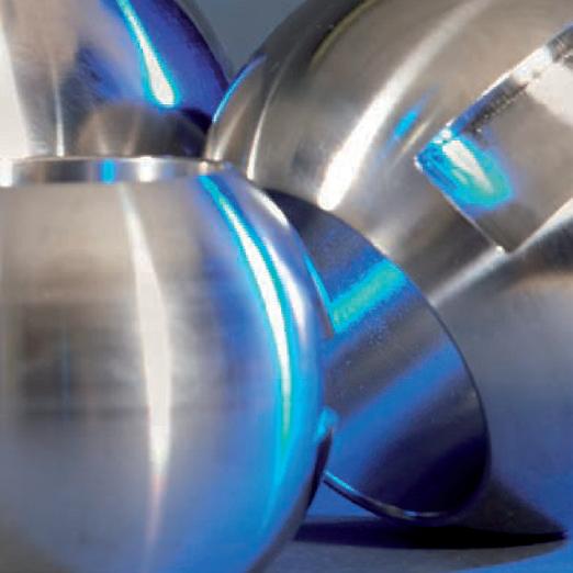
b- The valve’s internal parts such as ball, stem, seats, seals, gaskets shall be handled with care avoiding scratches or surface damage.
c- All tools and equipment for handling internal critical sealing parts shall be soft coated.
d- Valves can be fitted with gaskets or seals in PTFE, Buna, Viton, etc., hence high temperatures will damage sealing components.
e- Never part open valve, valve must be full open of full closed to avoid seal damage.
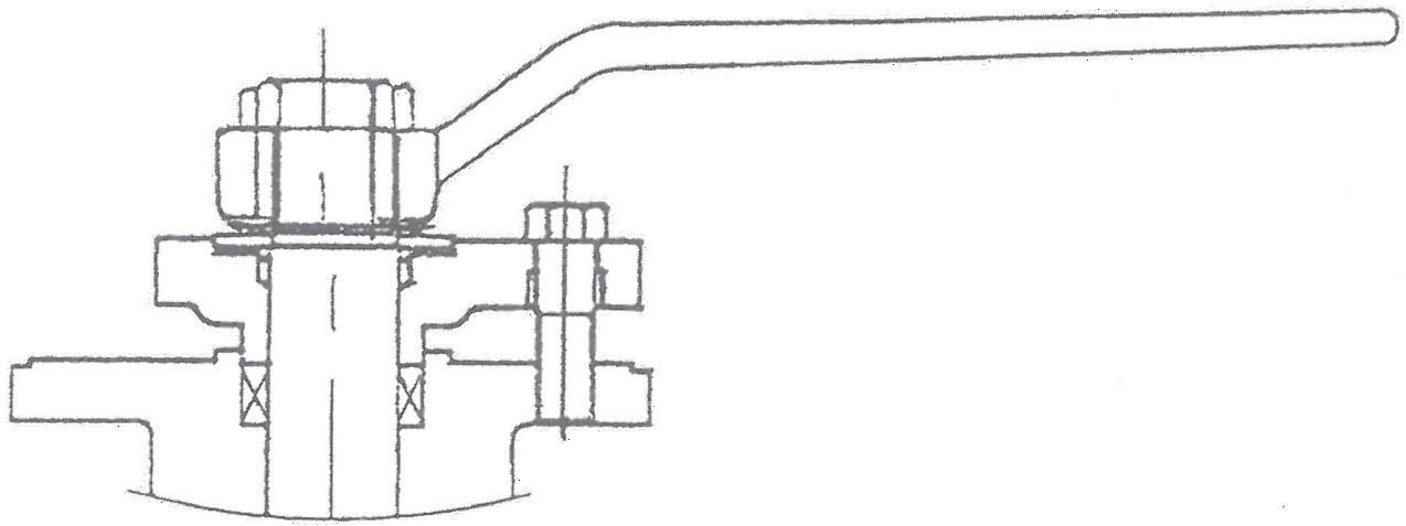
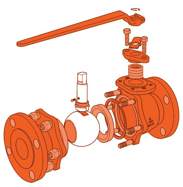
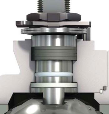
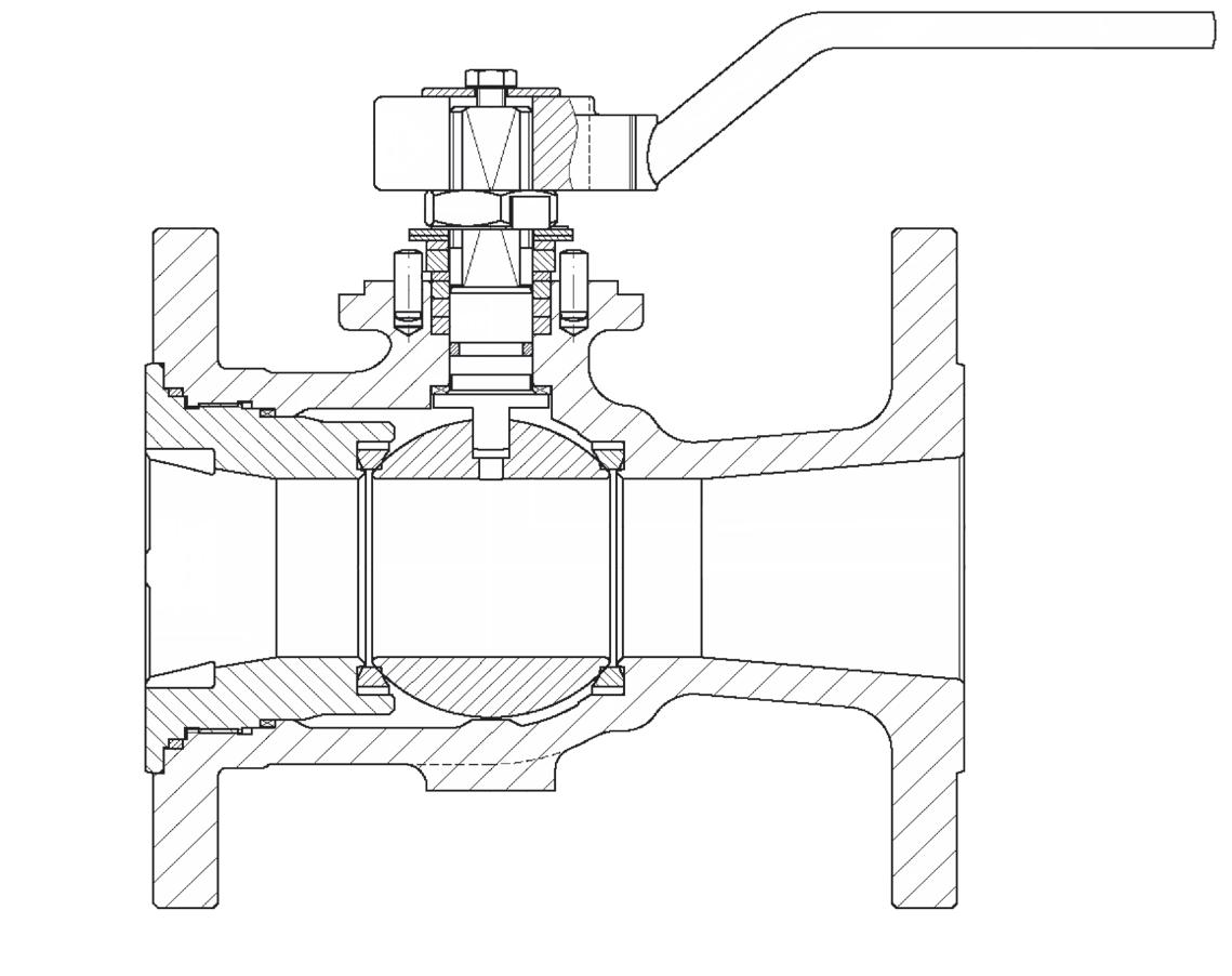
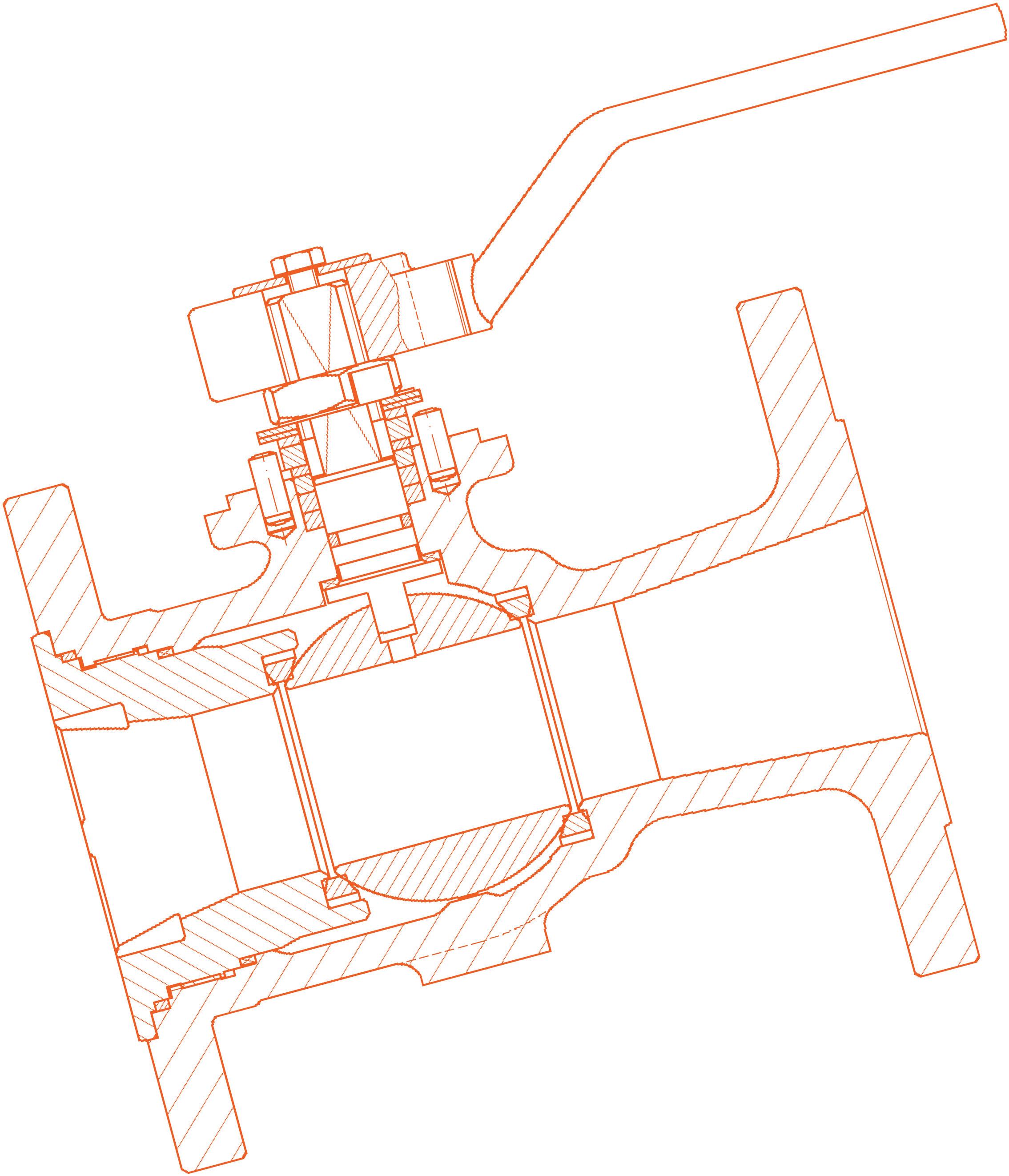
For all operations make reference to position number on part list of the applicable drawing listed.
1.0 SCOPE
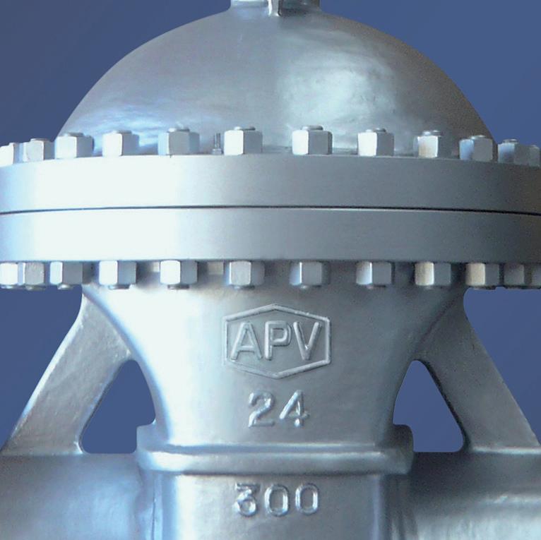
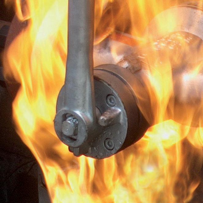
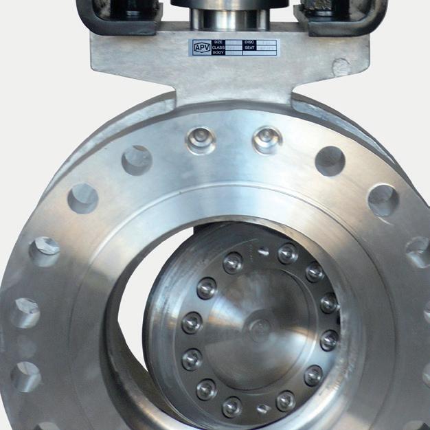
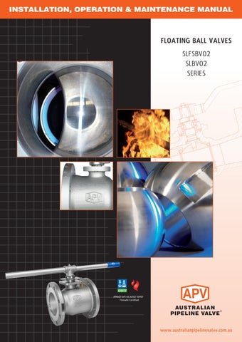
This manual describes the methods of installation and maintenance for floating ball valves, which are designed to fit between ANSI Class 150, Class 300 and Class 600 flanges (or can be buttweld one end). SLFSBV02 is firesafe. SLBV02 is not firesafe.
1.1 ENVIRONMENTAL CONSIDERATIONS
According to ISO 14000 regulations and the environmental policy of APV the recyclability of the components that form part of APV valves is as follows:
Recyclable components:
Metal parts, PTFE (hard), plastic plug (low-density polyethylene).
Non-recyclable components: PTFE mixed with other compounds (glass-fiber, graphite, etc.), nylon, graphite and graphite mixed with metal.
1.2 STORAGE
1.2.1 Temporary Storage
If valves are to be stored before installation, the following should be observed:
a) Keep the valves wrapped and protected as shipped from the manufacturer.
b) Do not remove the protective end covering until the valve is ready for installation. This will reduce the possibility of foreign material damaging the internal valve components.
c) Valves stored outdoors should be positioned such that water does not accumulate in the valve body.
1.2.2
Long Term Storage
If valves are to be stored more than one year, they should be prepared in the following manner:
a) Remove the packing and apply a preservative to the packing chamber.
b) Do not remove the protective end covering.
c) Do not store the valves outdoors.
1.3 PREPARATION
a) Remove the valve end protection.
b) Prior to shipment, a preservative/corrosion inhibitor may have been applied to the inner body of the valve. This preservative/corrosion inhibitor can be removed with a solvent provided the solvent used does not affect the seats/seals used in the valve.
c) The inside of the valve should be inspected and blown out with compressed air. Adjacent piping must be clean and free from debris to prevent damage to the valve.
d) To prevent valve distortion, inefficient operation or early maintenance problems, support piping on each side of the valve.
e) Make sure the valve is positioned such that there is sufficient space so that the hand wheel is easily and safely reached and there is enough clearance for the stem when the valve is open.
f) Install the valve according to the flow indicator on the valve body where applicable.
2.0 INSTALLATION
Piping should be properly aligned and supported to reduce mechanical loading on end connections. Never use the lever (wrench) to hold the valve during transport, handling or assembly.
The following procedure is required to be followed for correct installation.
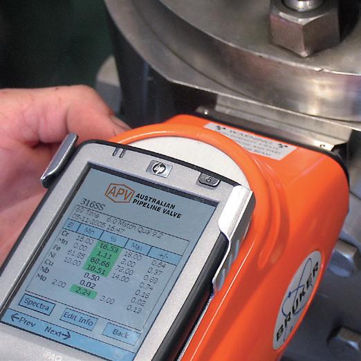
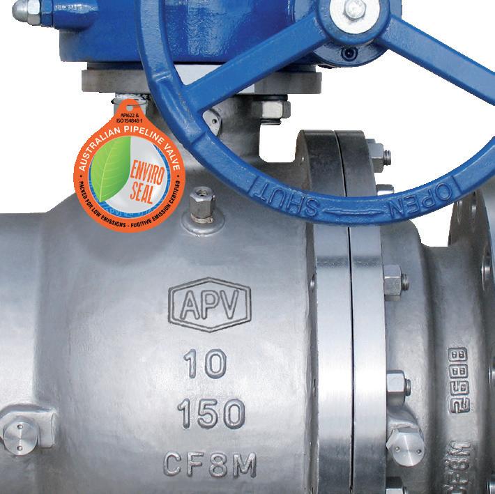
a) Before installation confirm the marking (rating, size and material) on the valve body and nameplate. Ensure the valve is suitable for the service which it is being used.
b) Body bolts and nuts on valve shall be checked and retightened if necessary in case loosened during installation.
c) Remove valve end protectors and ensure gasket faces are free from damage. Tighten all bolts between mating flanges and valve equally paying careful attention to properly tighten bolts. Ensure you rotate tightening procedure (opposing bolts sequentially) gradually increasing torque.
d) Prior to installation of valve, ensure the line is completely flushed to remove any debris as soft seated ball valves are easily damaged. Filters or strainers should be installed upstream to protect soft seated valves.
e) Valves will operate at any angle horizontally or vertically, although it is recommended you install valves in a vertical position with stem pointing upwards for ease of operation, inspection and accessibility.
2.1 INSTALLATION POSITIONS
Ball valves are usually bi-directional, and therefore may be installed in either direction. In some cases, ball valves such as metal to metal seated and low temperature valves may be unidirectional, in which case the direction of flow will be indicated on the valve body.
2.2 PREPARATION FOR INSTALLATION
• Remove protective end caps or plugs and inspect valve ends for damage to threads, weld ends or flange faces.
• Thoroughly clean adjacent piping system to remove any foreign material that could cause damage to seating surfaces during valve operation.
• Verify that the space available for installation is adequate to allow the valve to be installed and to be operated.
Ensure sufficient clearance for the stem in the full open position. Inadequate clearance for valves may add mechanical loading to the valve ends.
2.3 END CONNECTIONS
2.3.1
Threaded Ends
Check condition of threads on mating pipe. Apply joint compound to the male end of joint only. This will prevent compound from entering the valve flowpath.
2.3.2
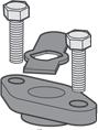
Flanged Ends
Check to see that mating flanges are dimensionally compatible with the flanges on the valve body ensure sealing surfaces are free of debris. Install the correct studs and nuts for the application and place the gasket between the flange facings.
Stud nuts should be tightened in an opposing criss-cross pattern in equal increments to ensure even gasket compression.
The responsibility for welding of the valves into piping systems is that of those performing the welding. Refer to ASME B31.1, B31.3 etc. Written welding procedures covering all attributes of the process and materials to be welded shall be in accordance with Section IX of the ASME Boiler and Pressure Vessel Code and any additional requirements from the applicable piping code including any possible necessary localised post weld heat treatment depending on material specifications.