Acknowledgement
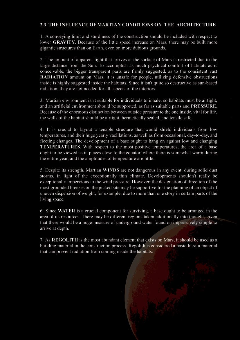
I consider it an opportunity to be associated with the Sal School of Architecture, Ahmed abad in our academic endeavor.
I express my heartfelt thanks towards my guide Prof. Kaustubh Mankodi, for their precious guidance; continue interest and encouragement towards the completion of this study. Their critical inputs and sound guidance have enriched the value of the thesis.
Principal and Prof. Ramanjyot Srivastava, Head of the department of architecture (SSA), Ahmedabad is thanked gratefully for their encouragement of thesis work. I would also like to express my gratitude to all my college faculties for their knowledge and appreciation.
I am thankful to my colleagues and friends who have support me in the preparation of this report and hereby thanking them for their invaluable inputs and cooperation.
At the same time, I wish to acknowledge the continued support and encouragement of my family during the preparation of this project.
i
ii1
iii
iv
v
vi

vii
viii
1
2
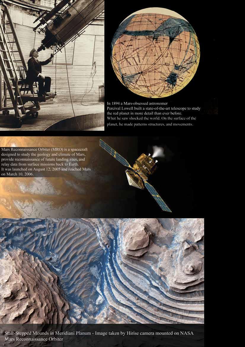
Figure 1 - Percival Lowell in 1914
Figure 2 - Appearance of Mars in 1905
Figure 3 NASA’s Mars Reconnaissance Orbiter
3
4
Figure 4 Race to Mars- artwork by Reza Bassiri
5
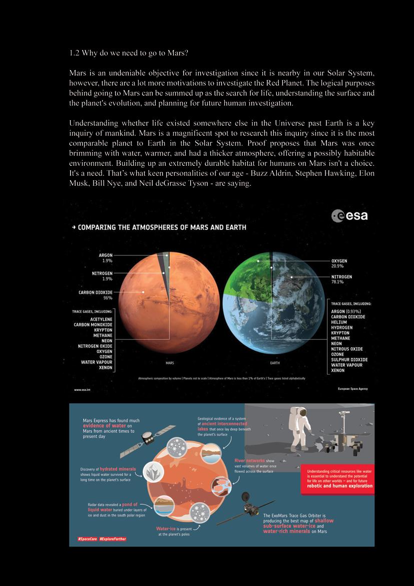
Figure 5 Comparing the atmospheres of Mars and Earth
Figure 6 Ten things about Mars Figure 6 Ten things about Mars
6
7
8
9
10
11
12
13
14
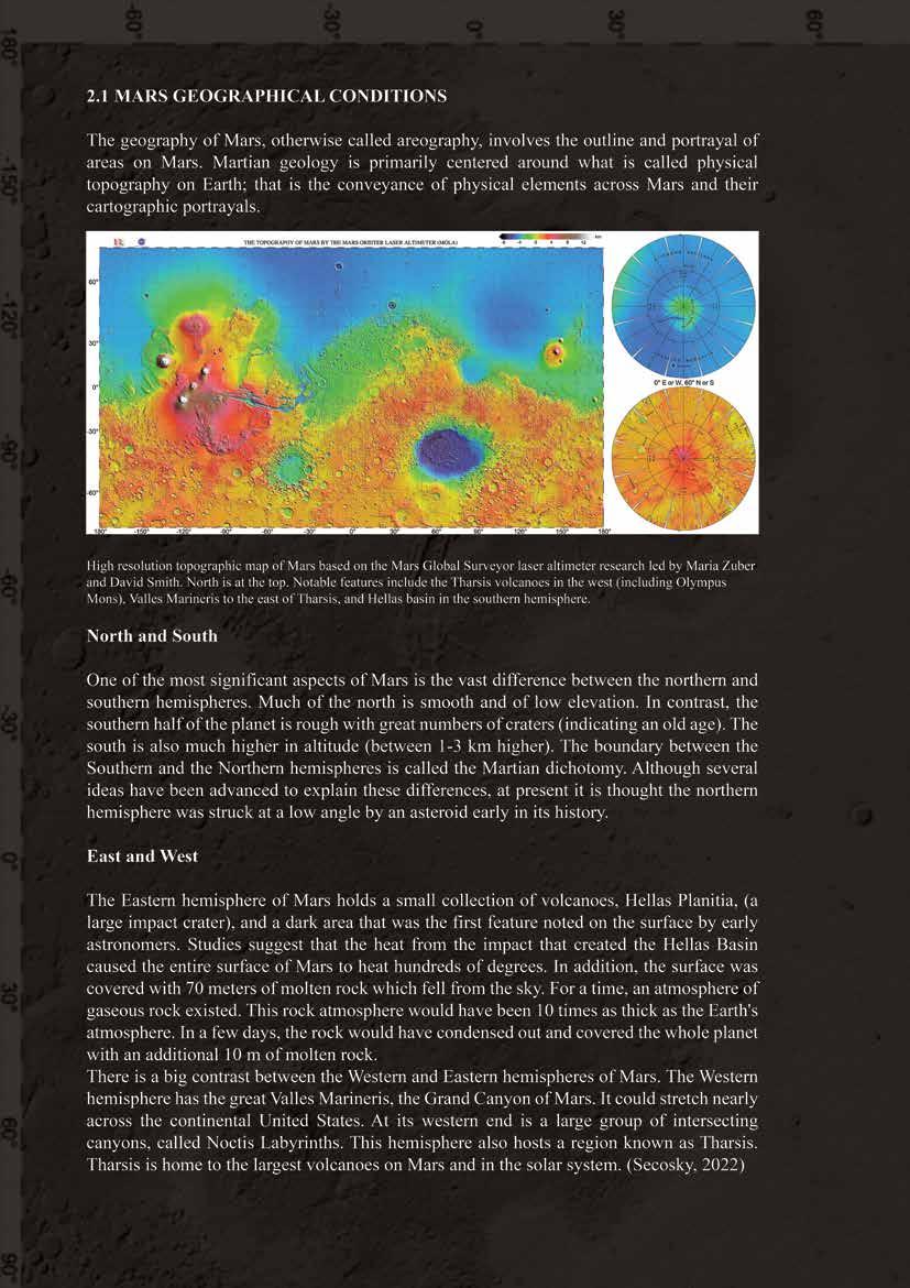
Figure 7 MARS ORBITER LASER ALTIMETER (MOLA)
Figure 8
15
Figure 9
16
17
Figure 10 The north–south martian divide
18
19
20
21
22

23
24
25
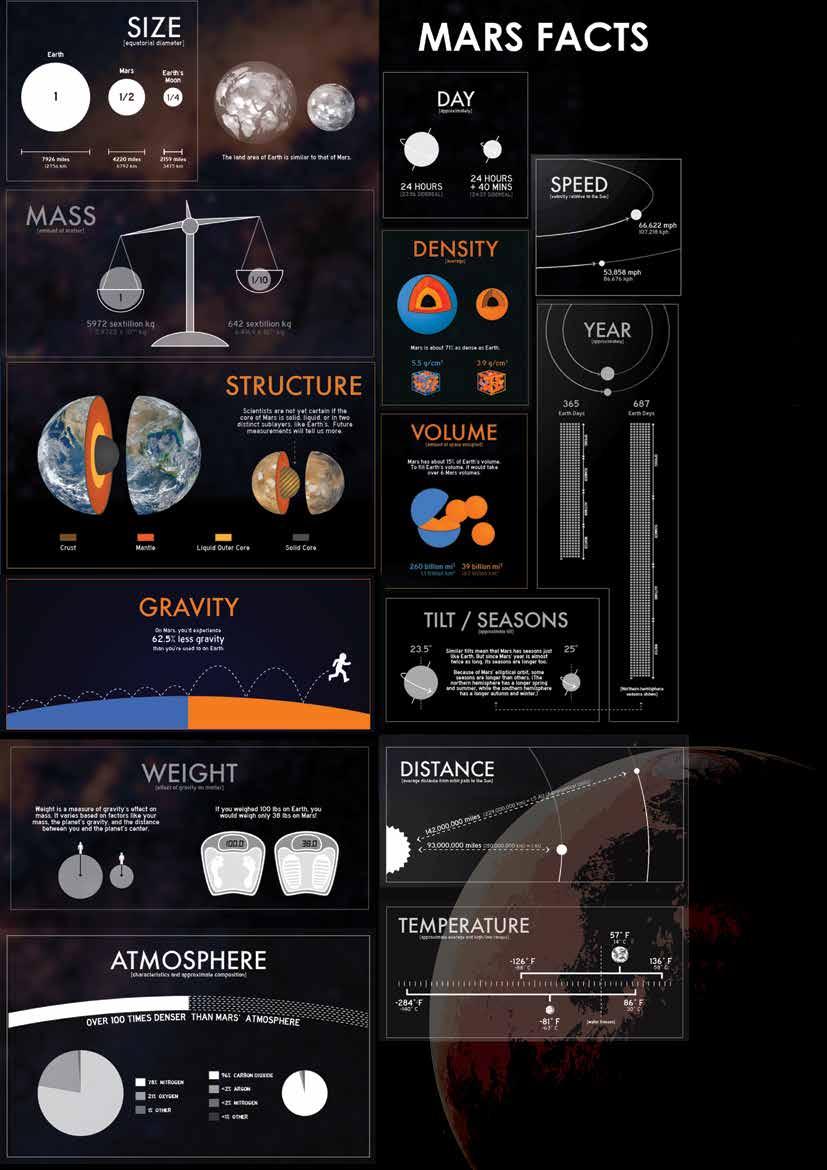
Figure 11 Mars Quick Facts
26
27
28
29
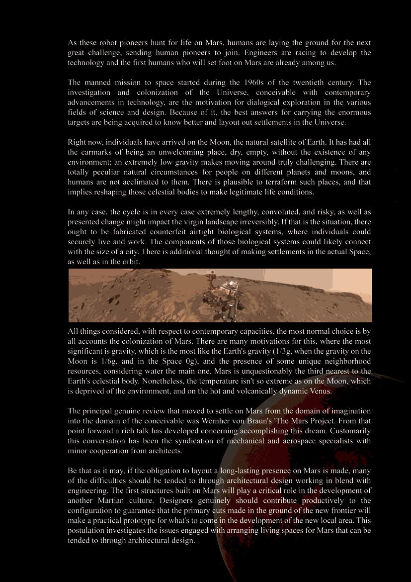
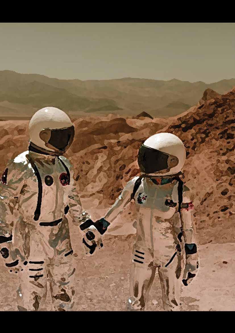
Figure 12 An Astronaut Couple on an Unknown Planet
30
31
32
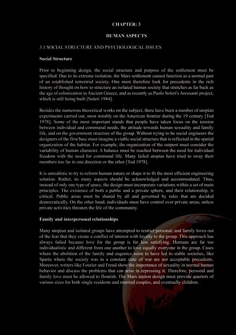
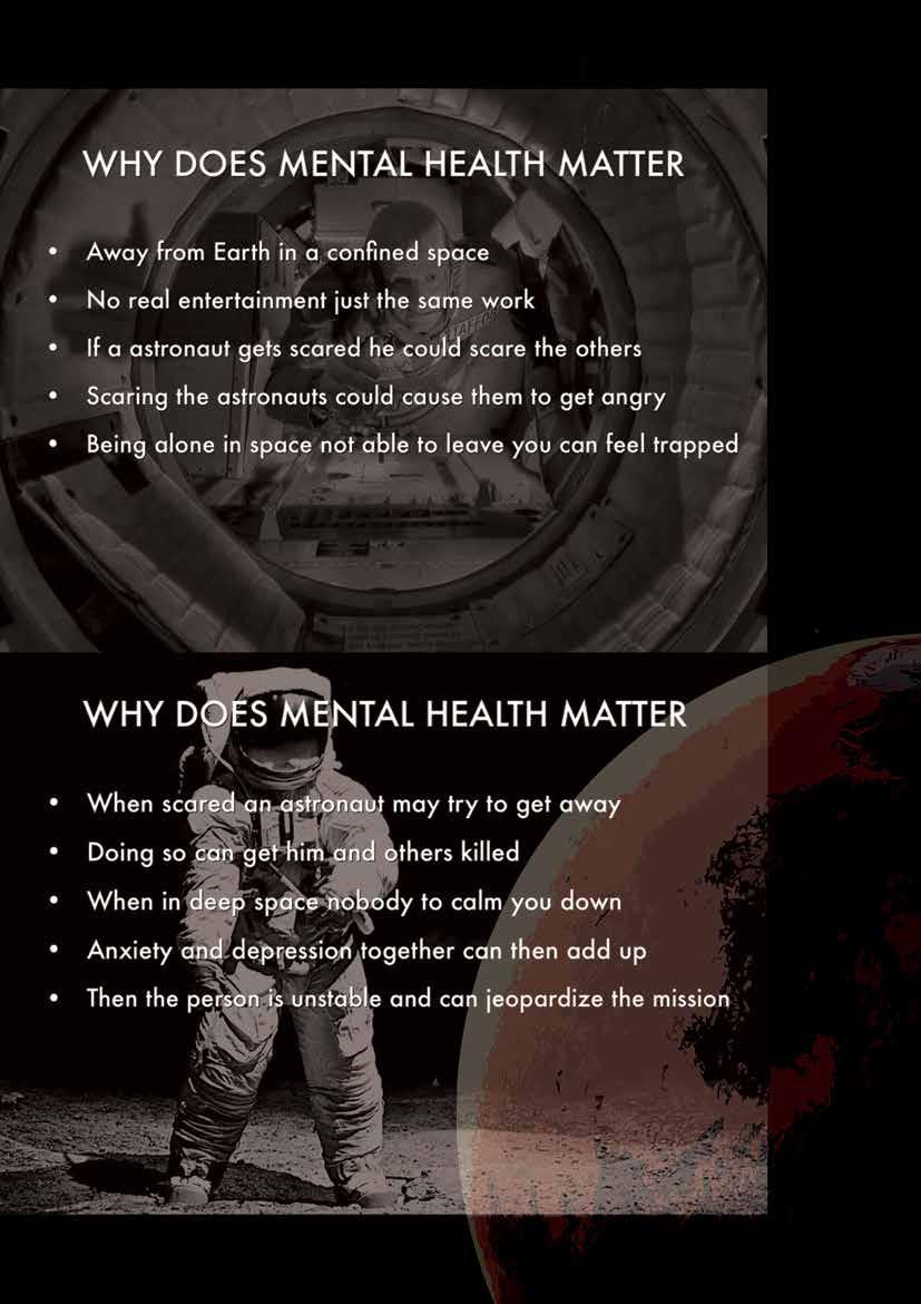
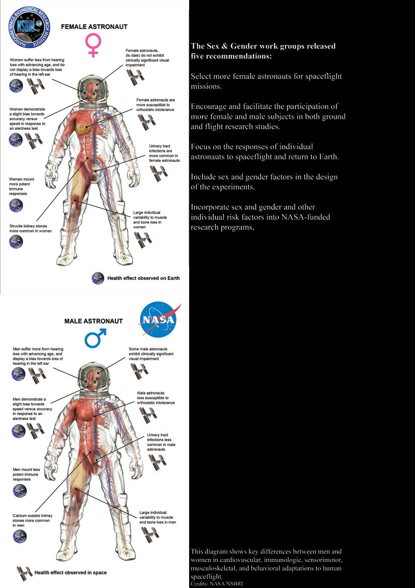
Figure 13 Astronaut Mental Health
33
34
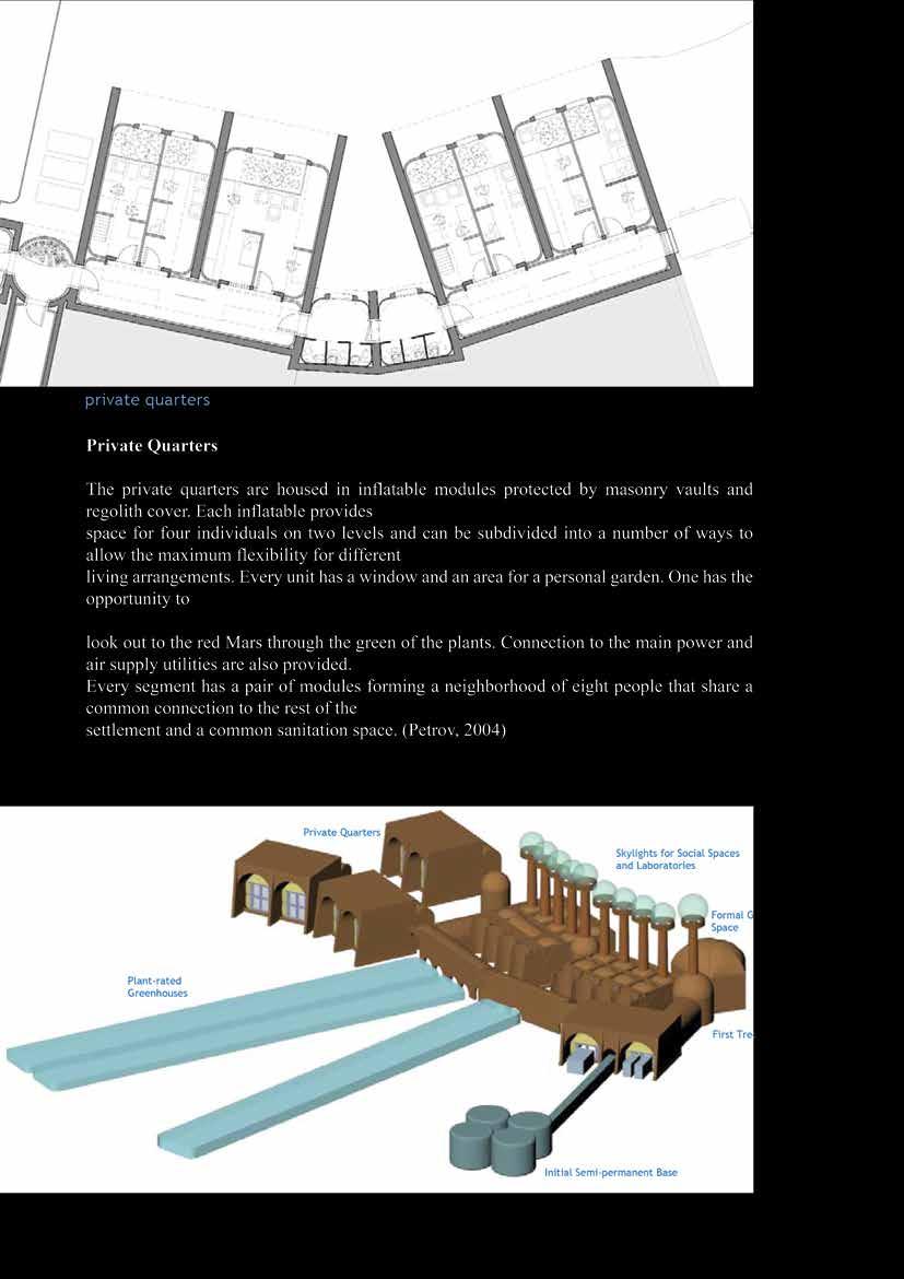
Figure 14 private quarters - petrov mars settlement
Figure 15 computer model without the site – petrov
35
36
37
38
39
40
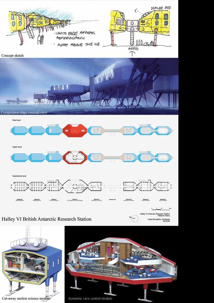
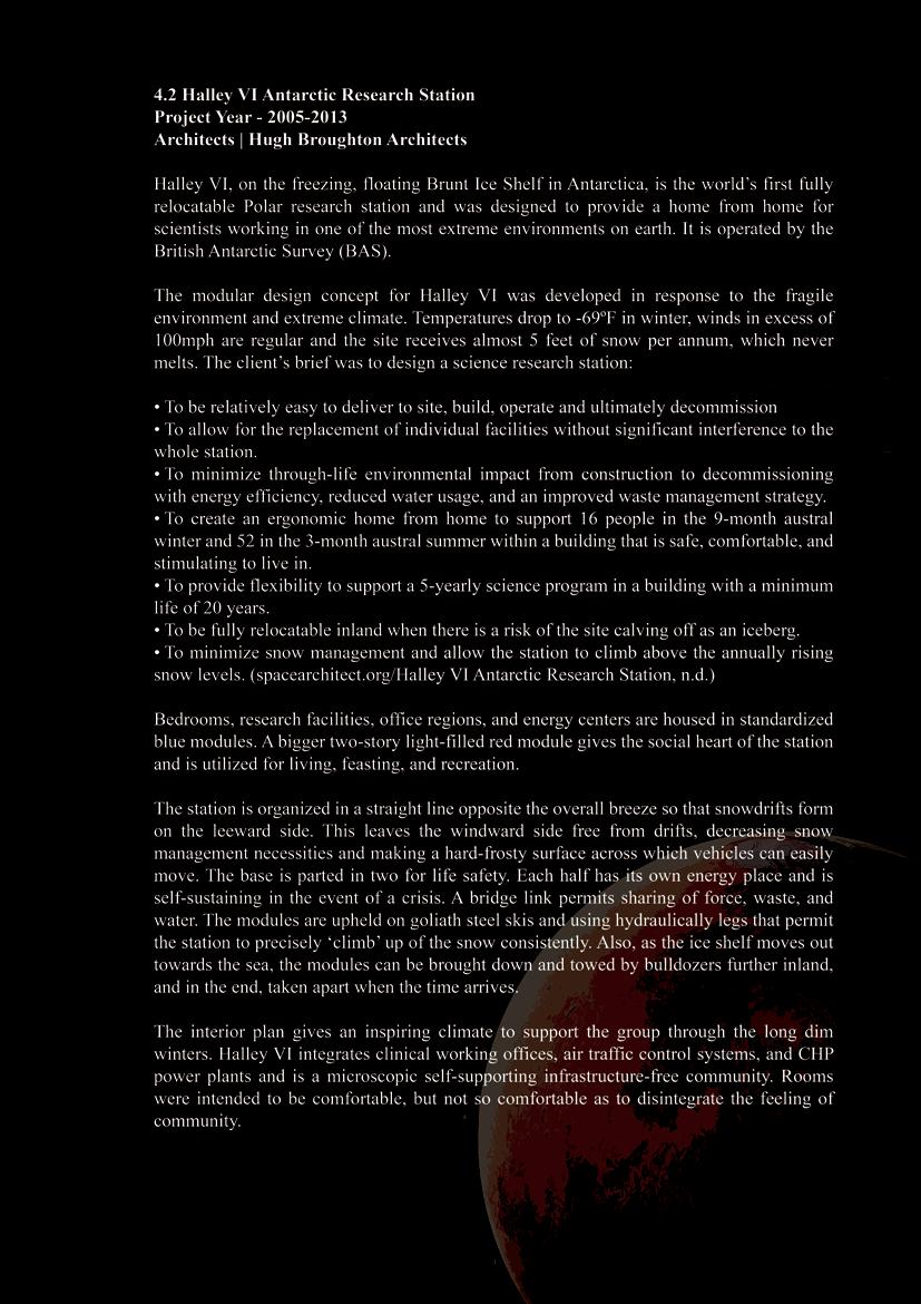
Figure 16 Halley VI Antarctic Research Station data
41
42
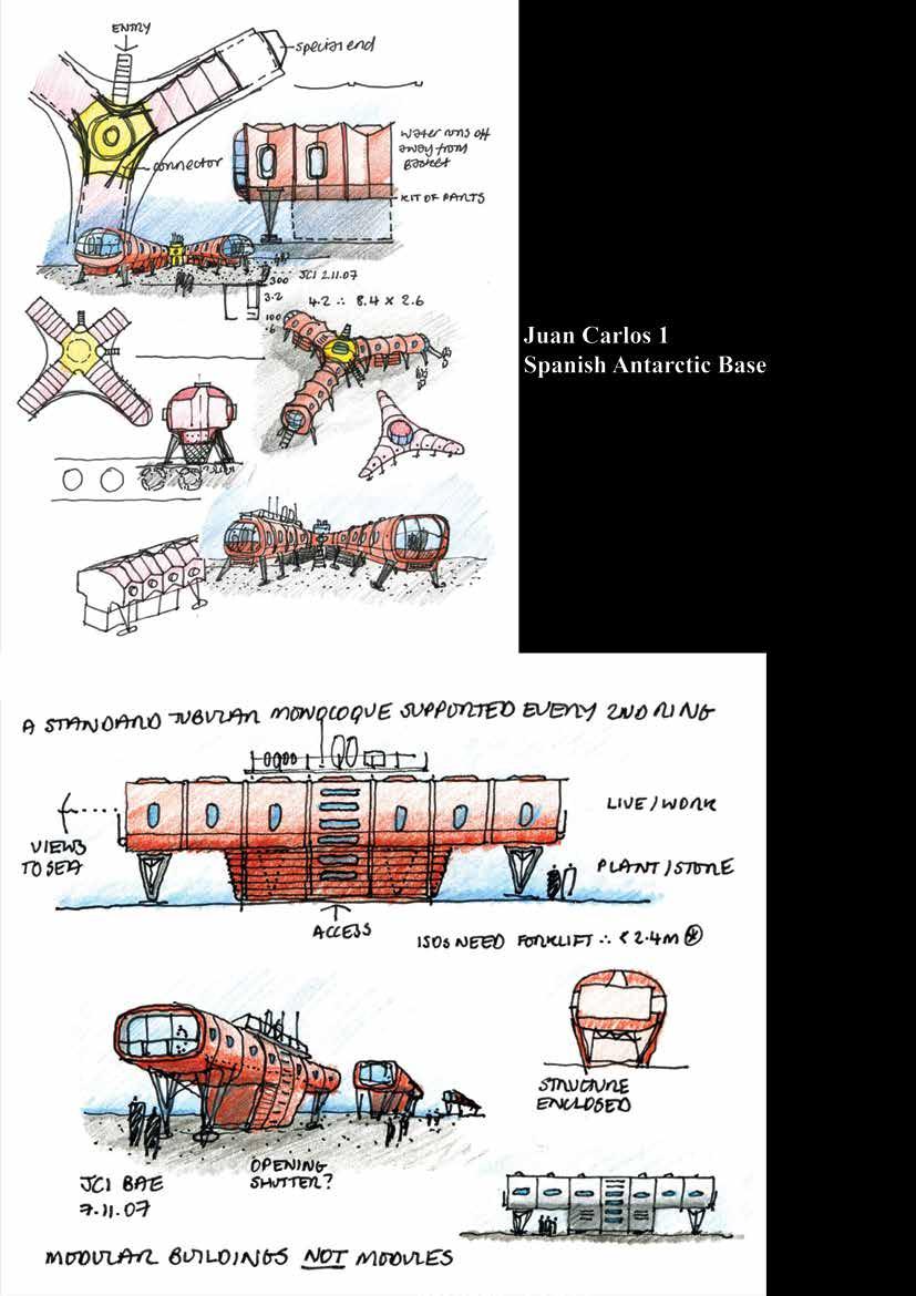
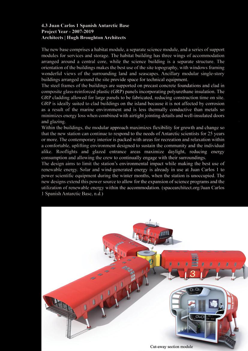
Figure 17 Juan Carlos 1 Spanish Antarctic Base
43
44
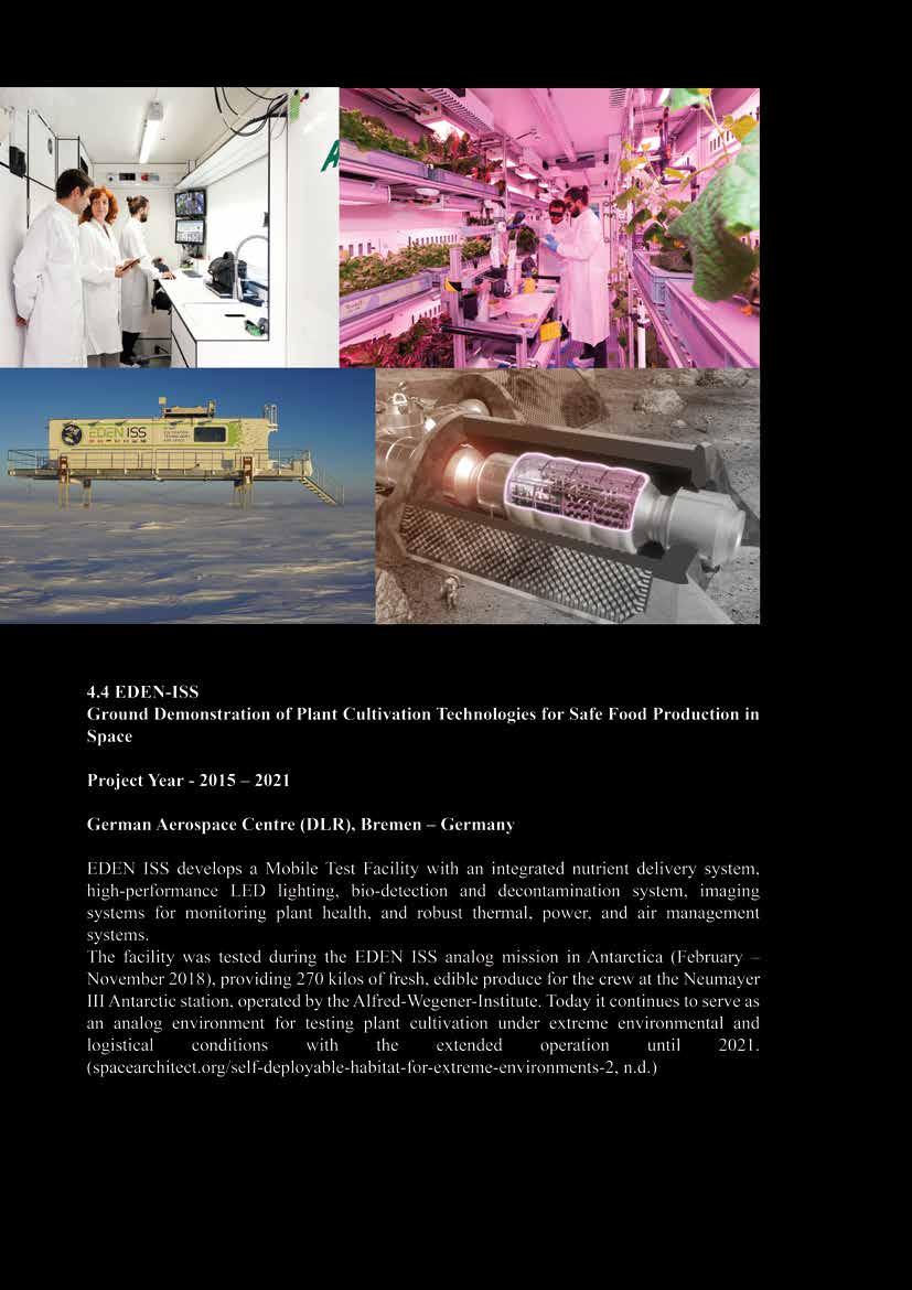
Figure 18 EDEN-ISS
Figure 19 PASSIVE SOLAR GAIN
45
46
Figure 19 PASSIVE SOLAR GAIN
Figure 21 A MIX OF RENEWABLE ENERGY SOURCES
47
48
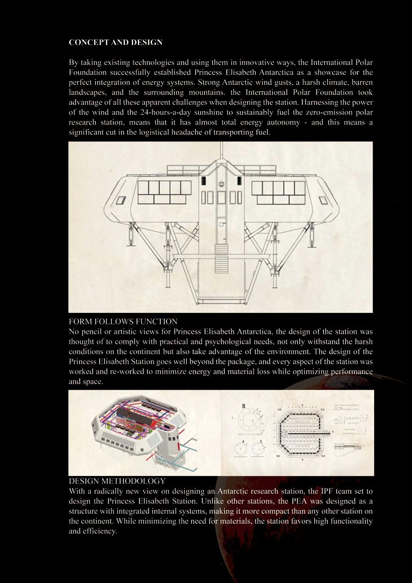
Figure 22 CONCEPT AND DESIGN
49
50
51
52
53
54
55
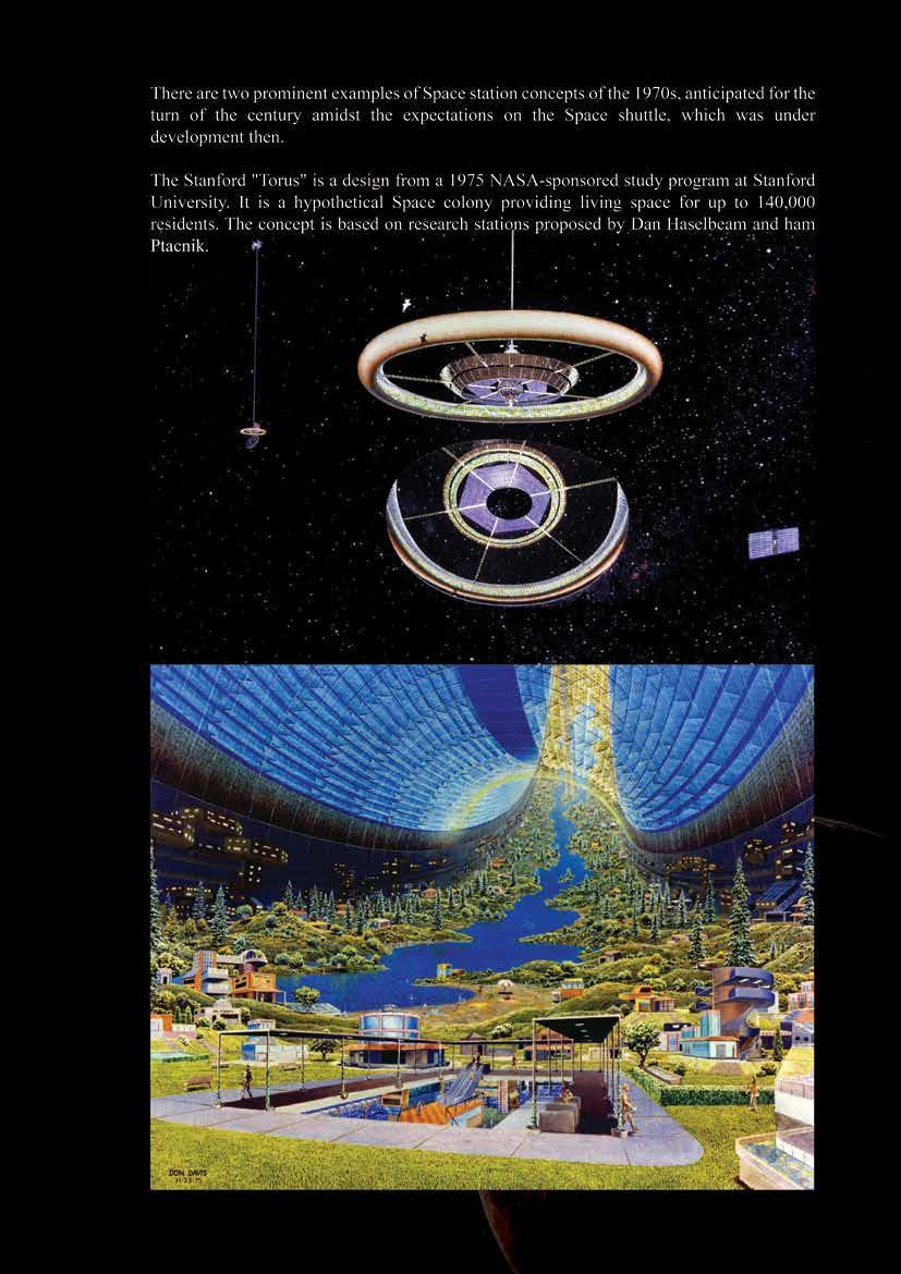
Figure 24 Torus Stanford
56
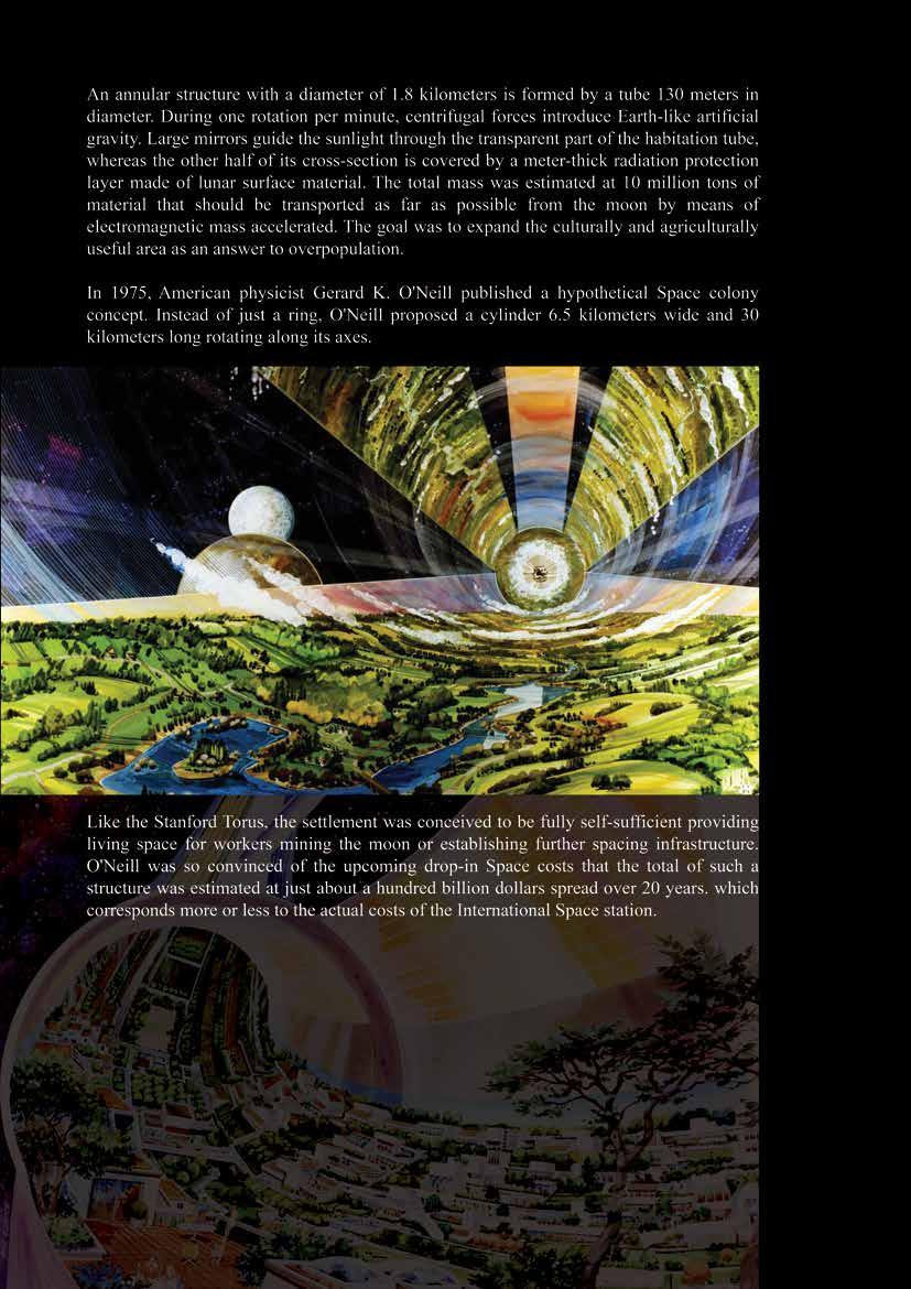
Figure 25 Rendering of O’Neill Cylinder by Rick Guidice
57
58
59
60
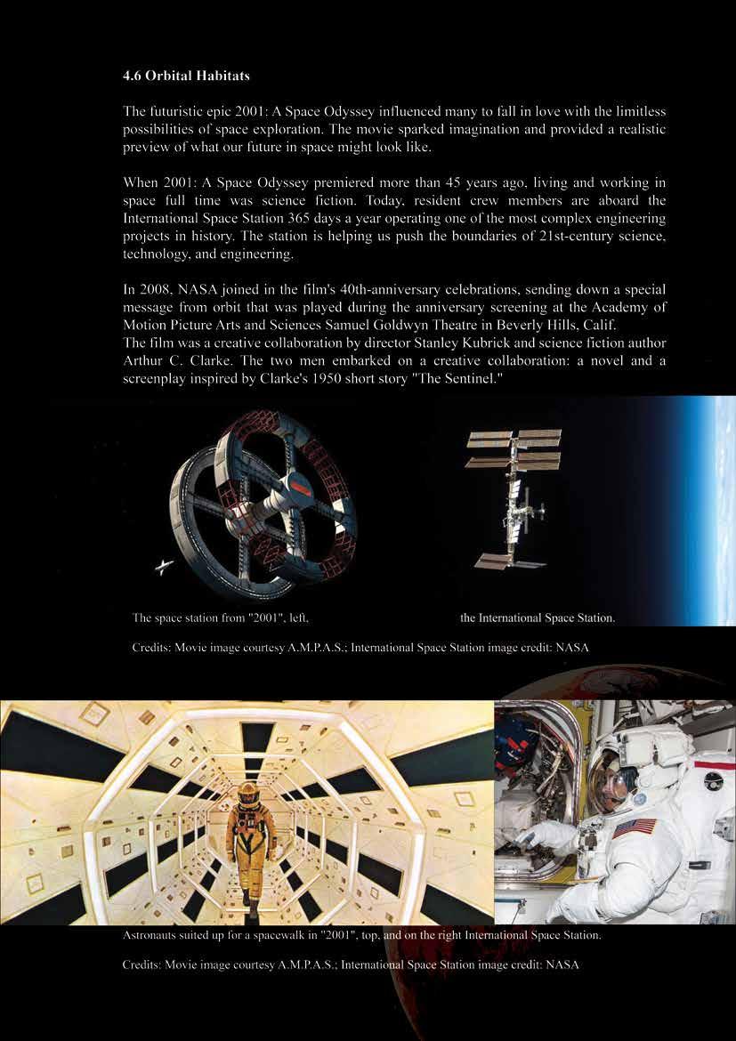
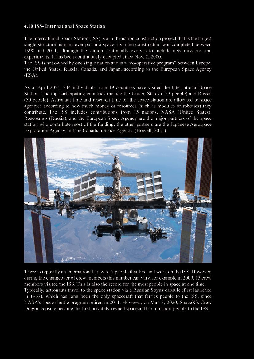
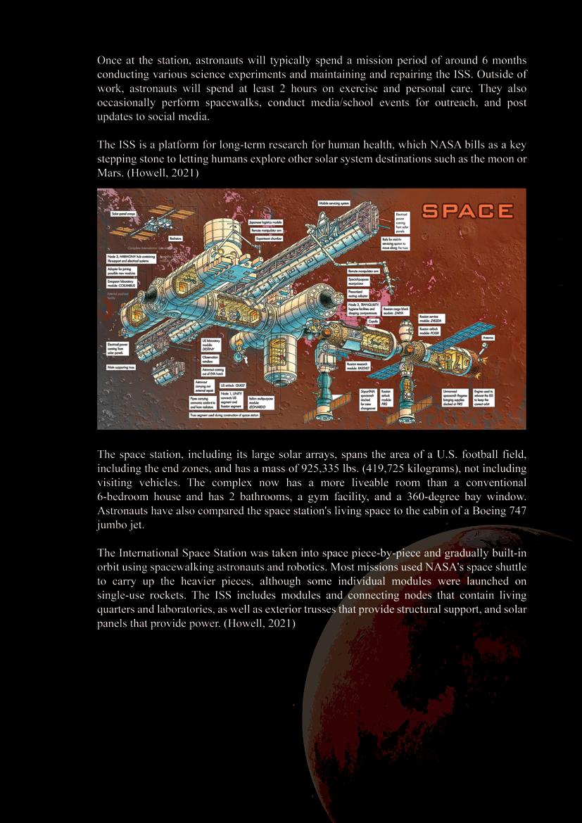
Figure 26 The International Space Station is pictured from the SpaceX Crew Dragon Endeavour
61
62
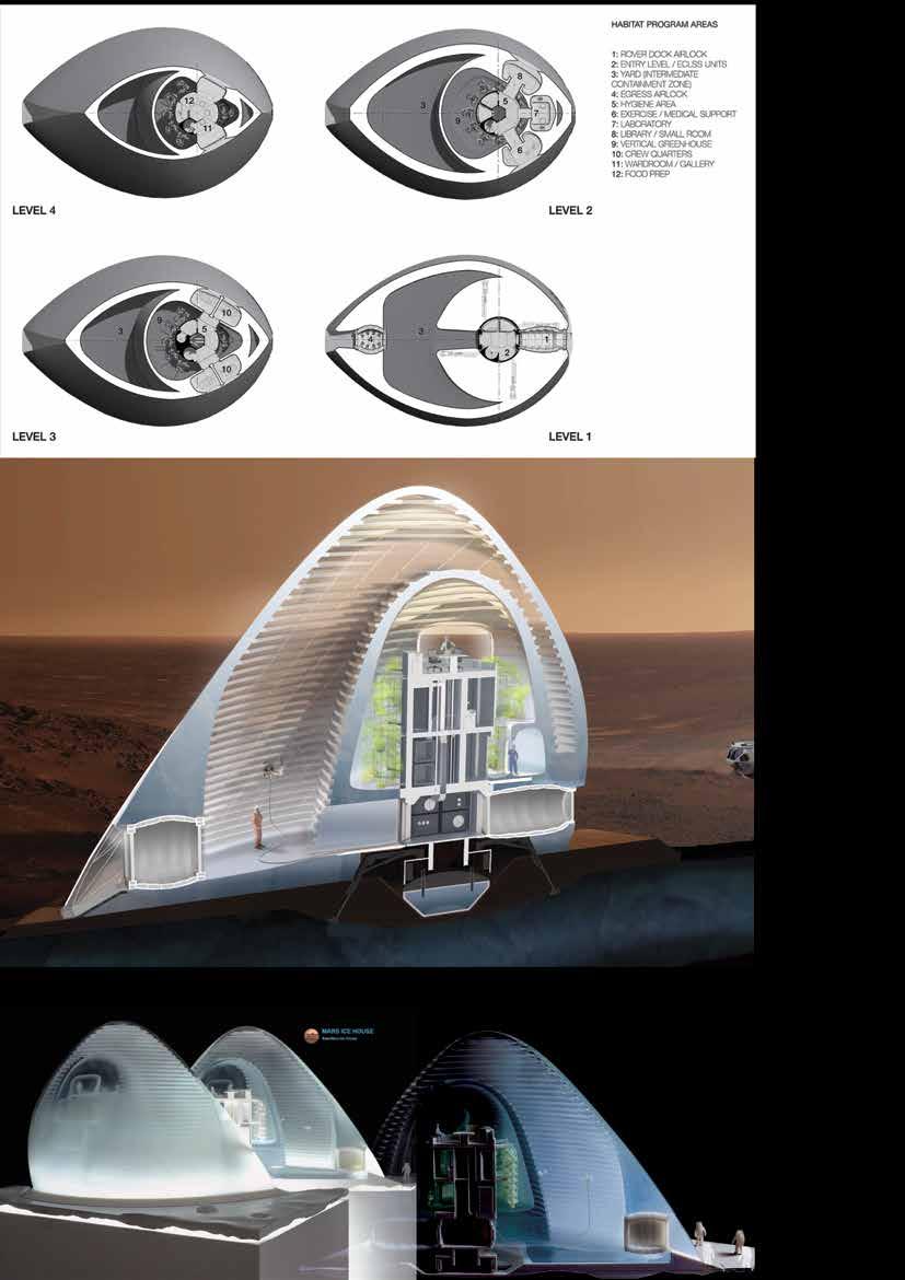
Figure 27 Sectional view through the interior revealing double wall condition, vertical garden, and interstitial “yard.”
63
64
65
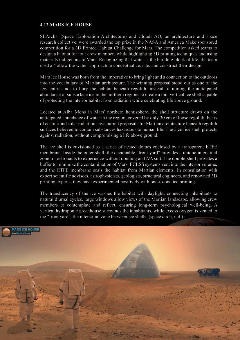
Figure 28 Mars Ice House, SEArch+ / Clouds AO
66
67
68
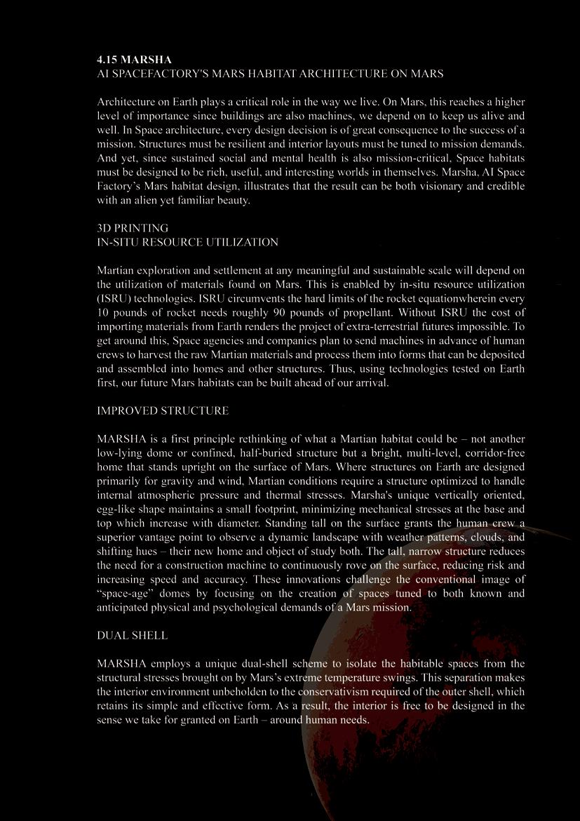
Figure 29 AI Space factory Marsha
69
70
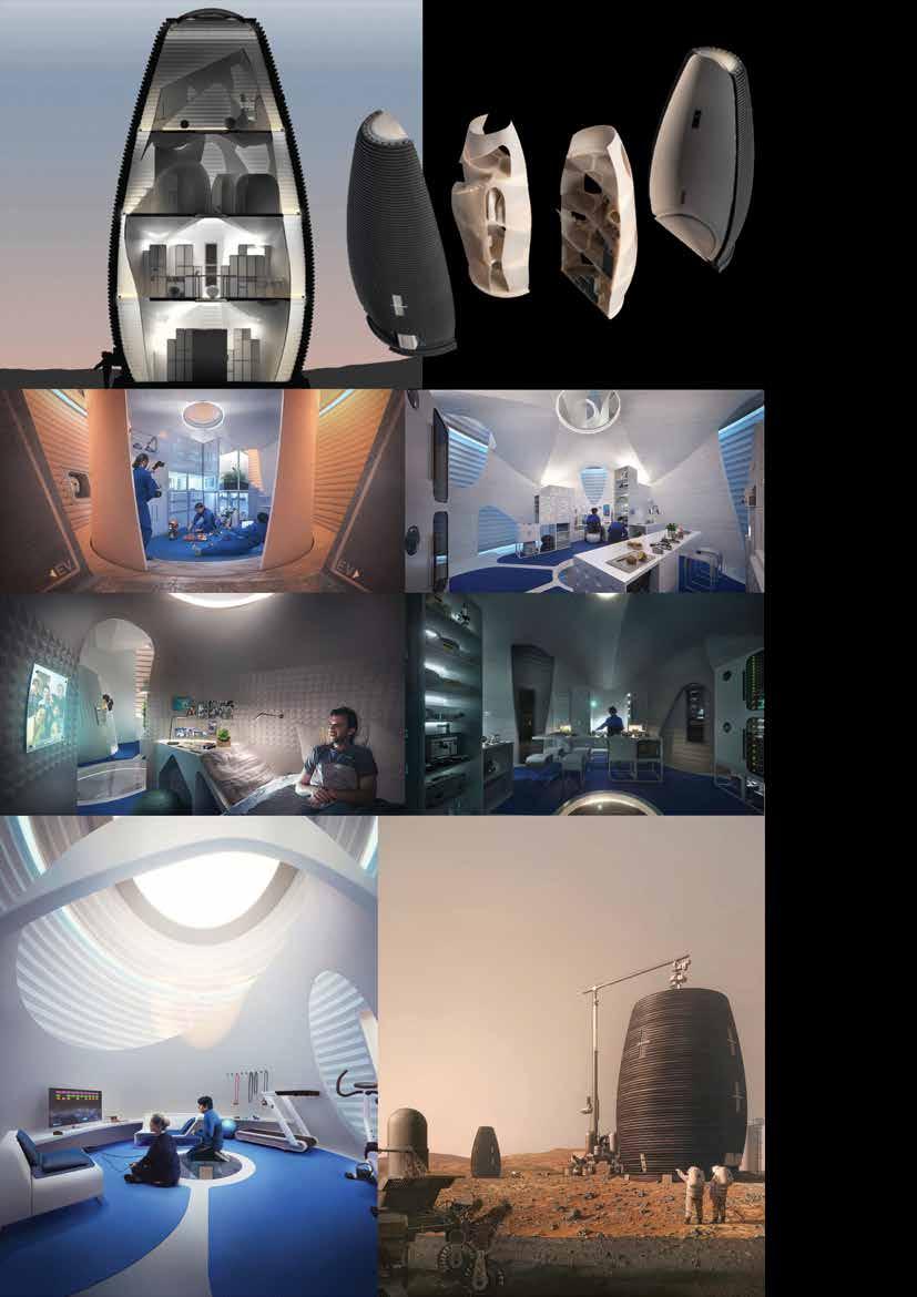
Figure 30 DUAL SHELL
71
72
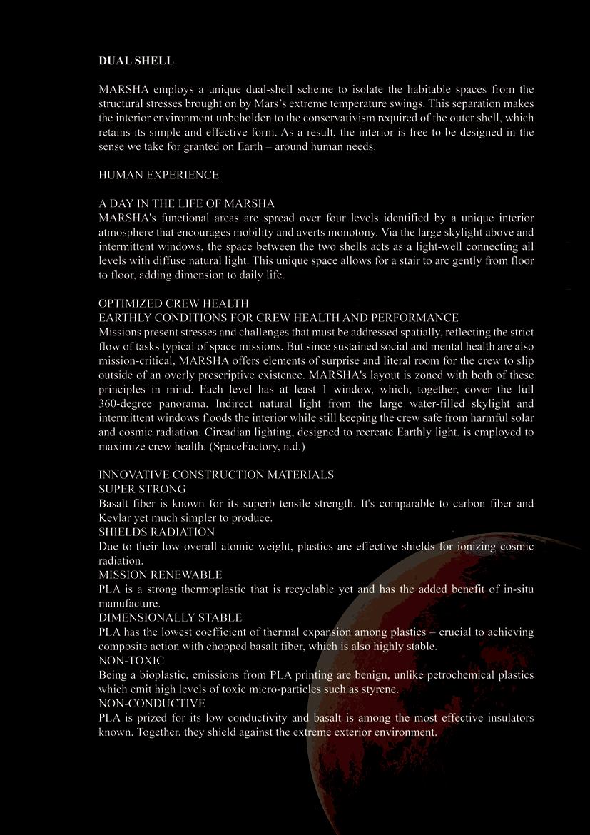
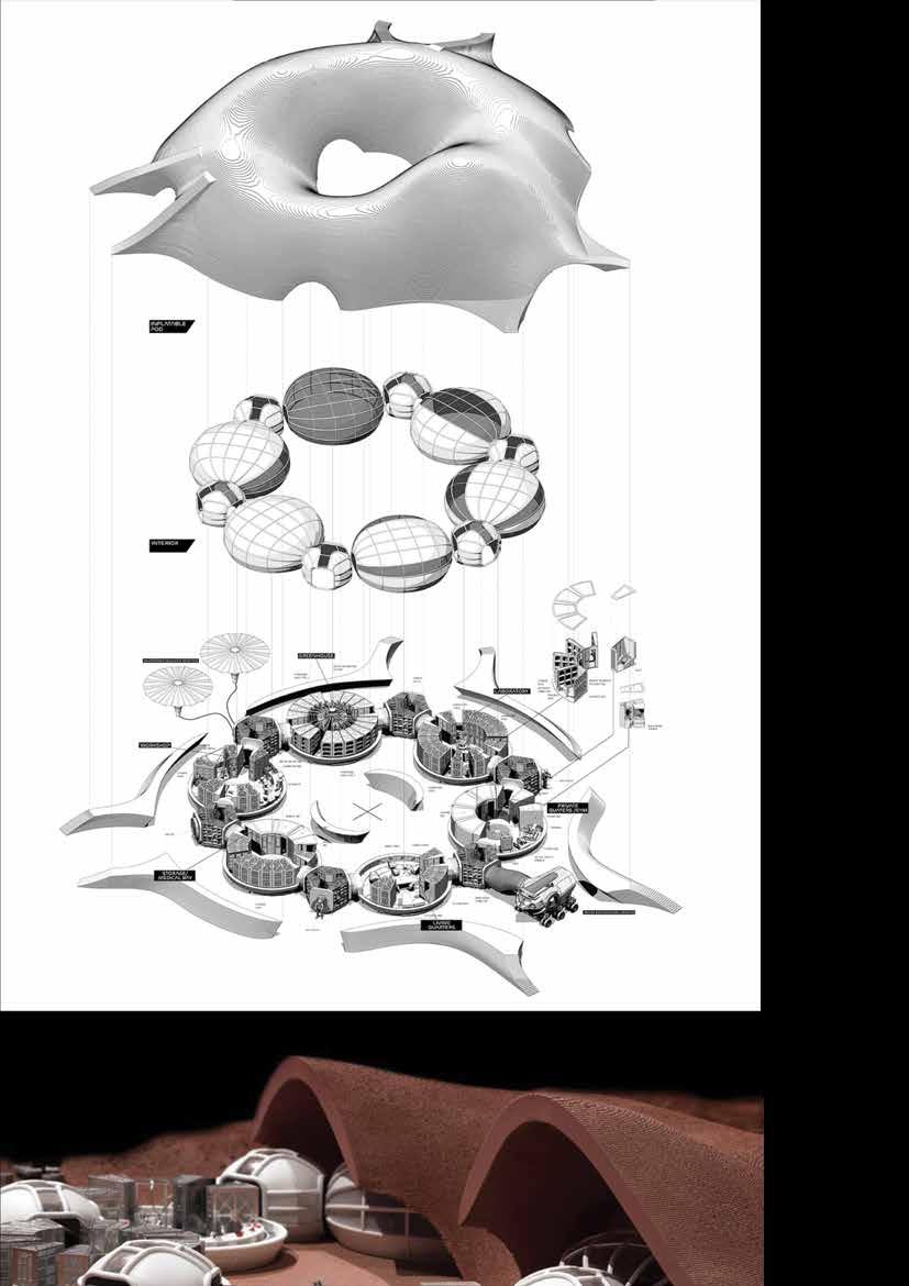
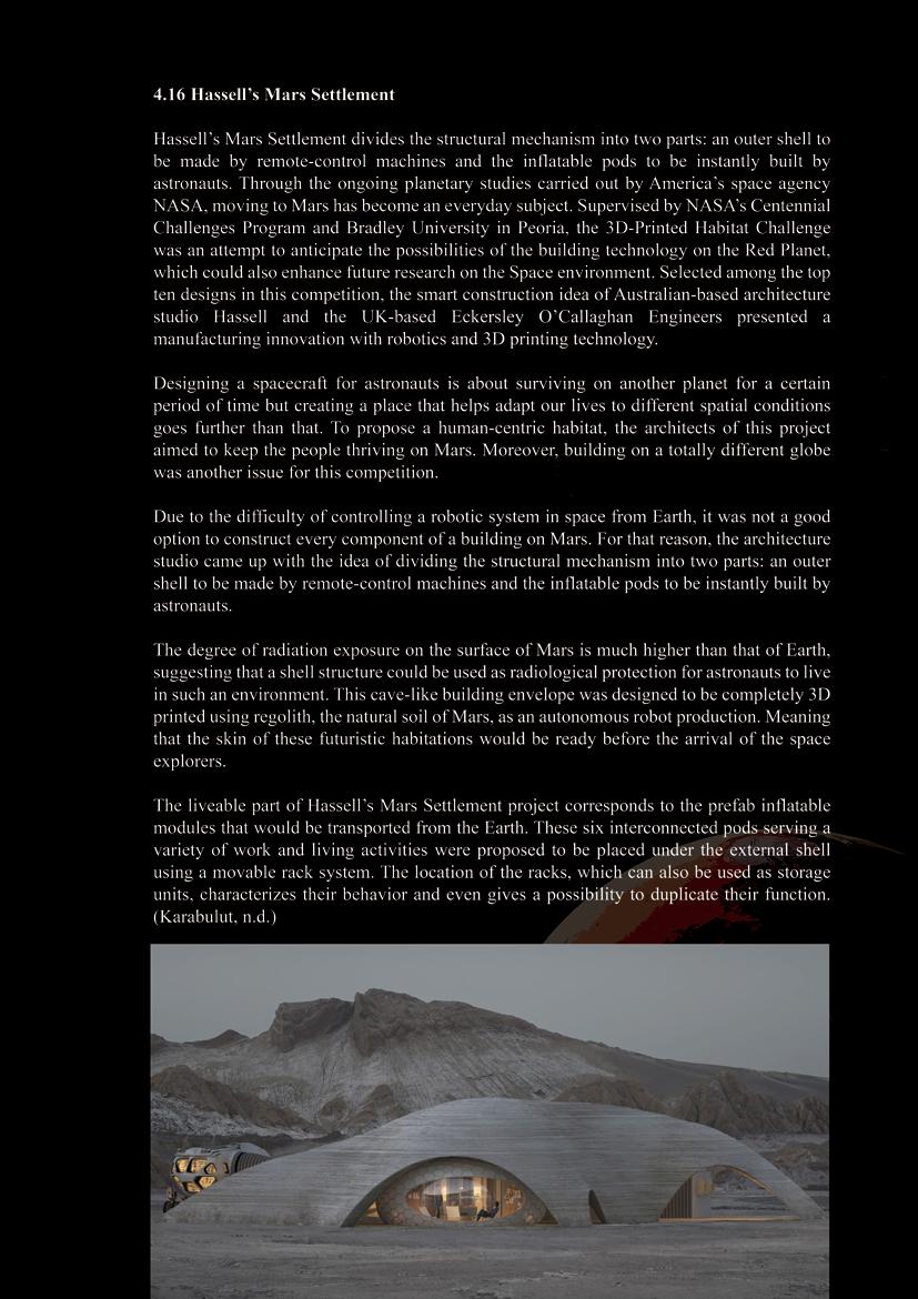
Figure 31 Exploded view - Hassell’s Mars Settlement
73
74
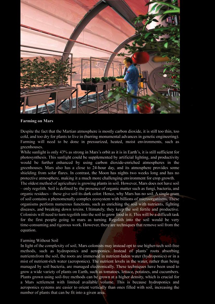
Figure 32 Inflatable Greenhouse - NASA
75
76
77
Figure 33 Concept art of the Mars deep drilling project
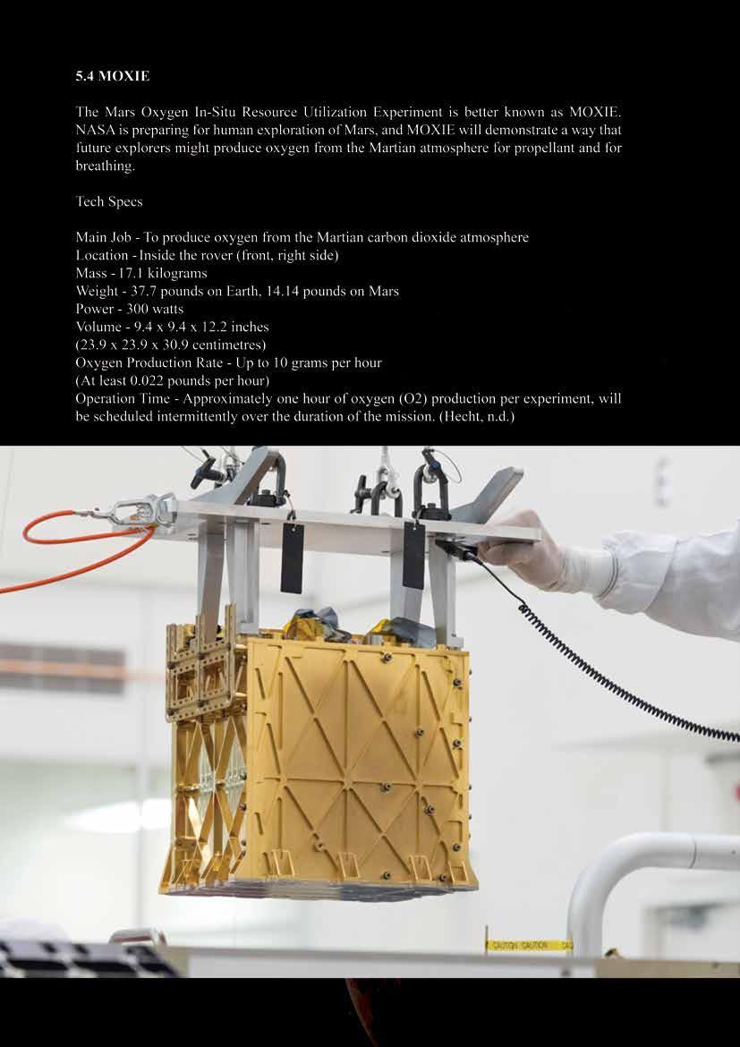 78 Figure 34 MOXIE is lowered into the rover in a sterile laboratory by technicians, to decrease the risk of dust and other particles interfering with the instruments. Credit: NASA/JPL-Caltech
79
80
81
82
83
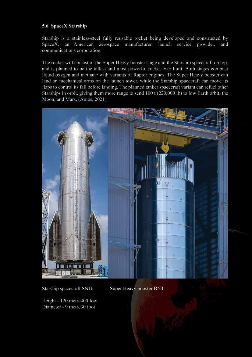
Figure 35 Leeward angle of Starship SN16 spacecraft

84
Figure 36 Cutaway schematic of SpaceX Starship interior by Tom Dixon
85
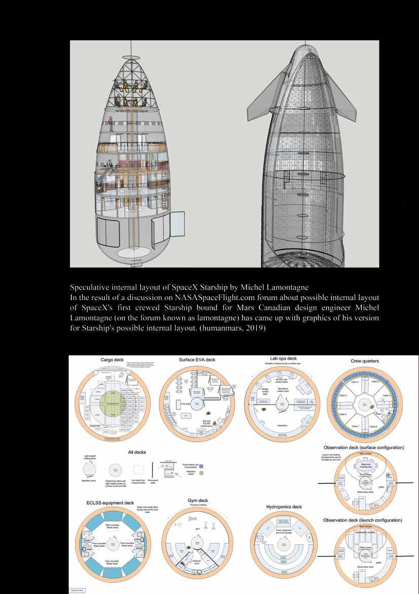
Figure 37 Speculative internal layout of SpaceX Starship by Michel Lamontagne
86
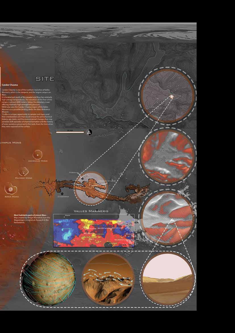
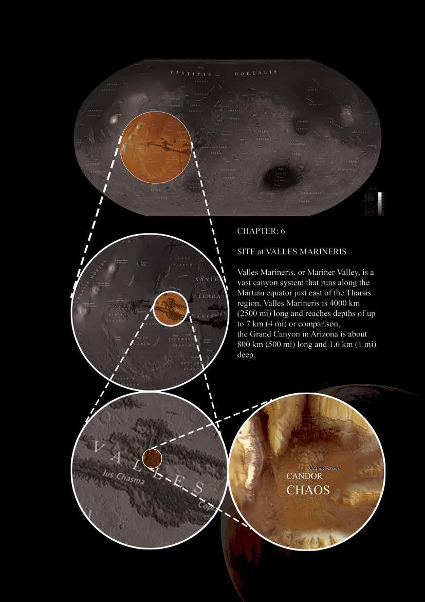
Figure 38 Site location - valles marineris
87
88
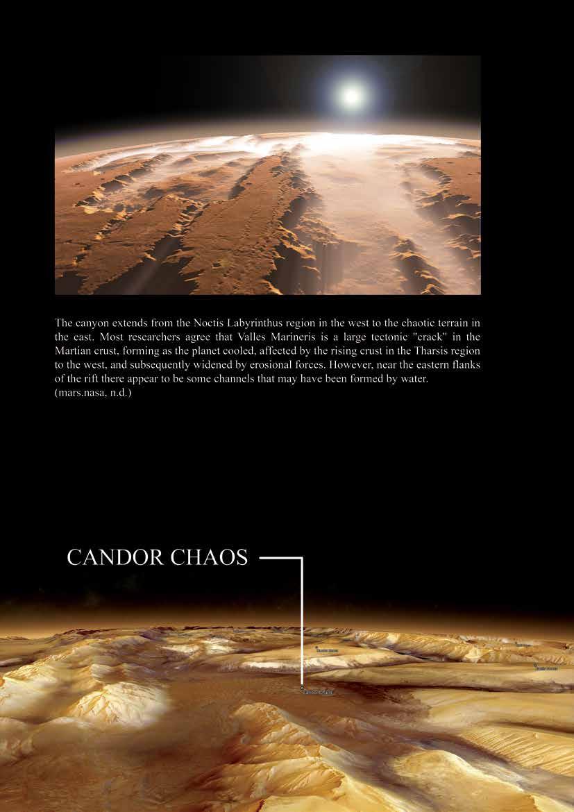
Figure 39 Artist’s concept of the Valles Marineris canyons on Mars
89
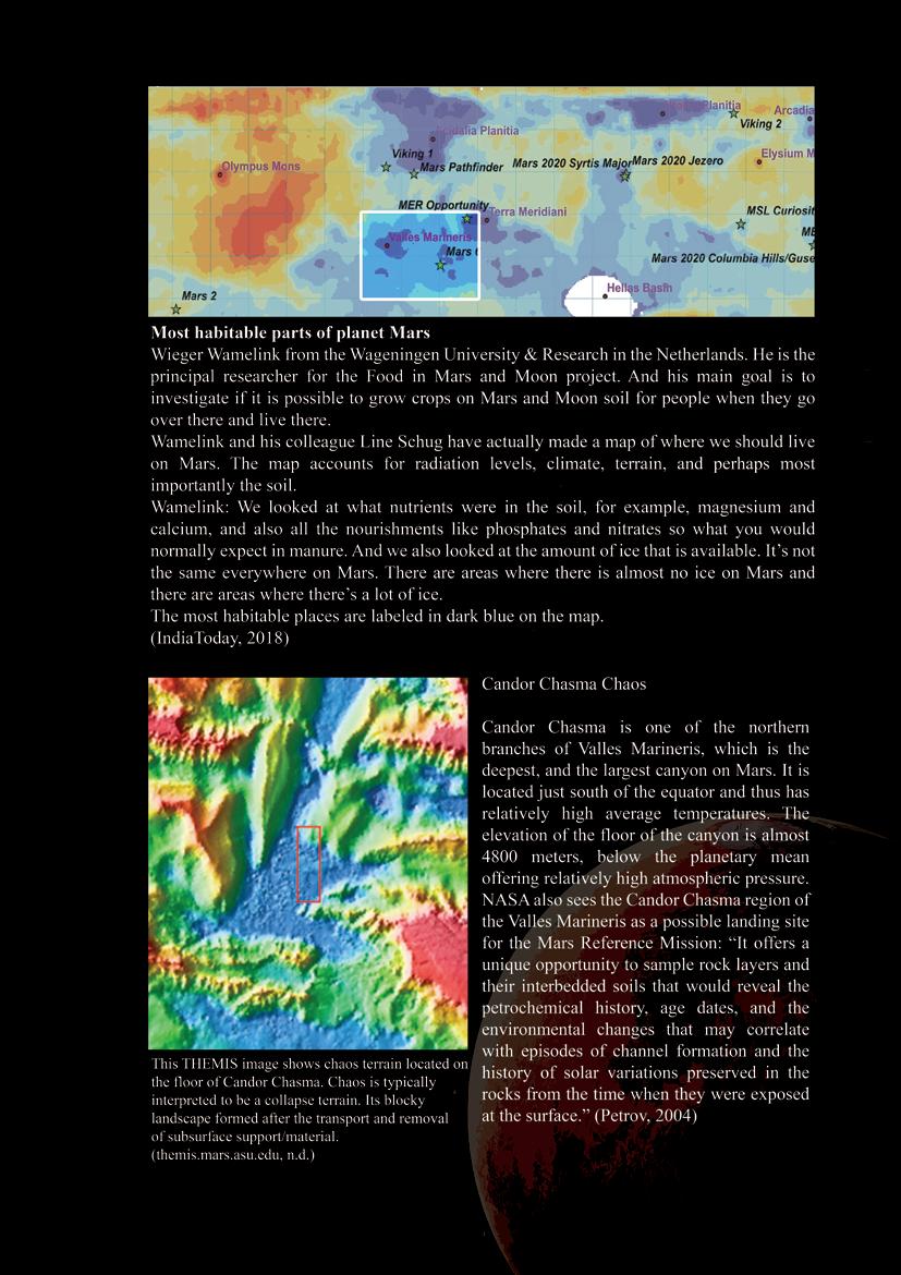
Figure 40 Map of the ideal landing sites on Mars from a plant perspective. Blue colours indicate high potentials, with the darkest blue as the best sites
90
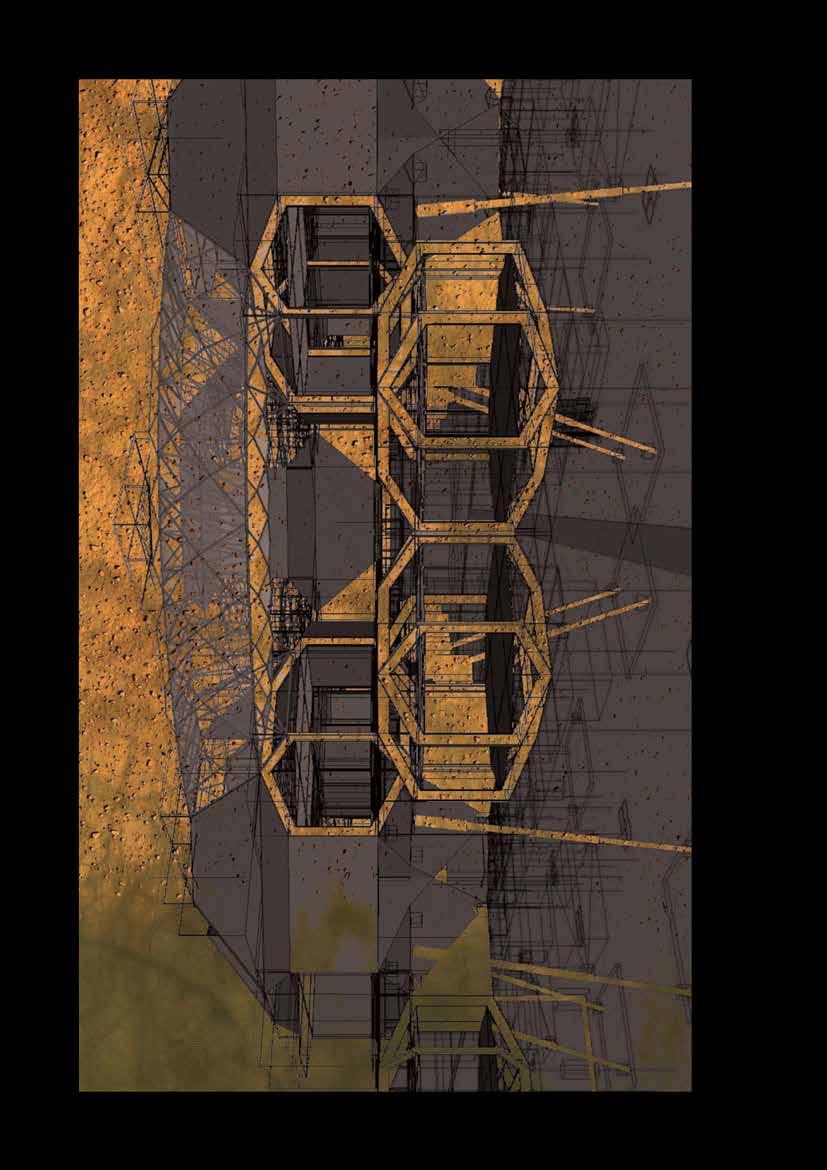
Figure 41 Form inferences

91
92
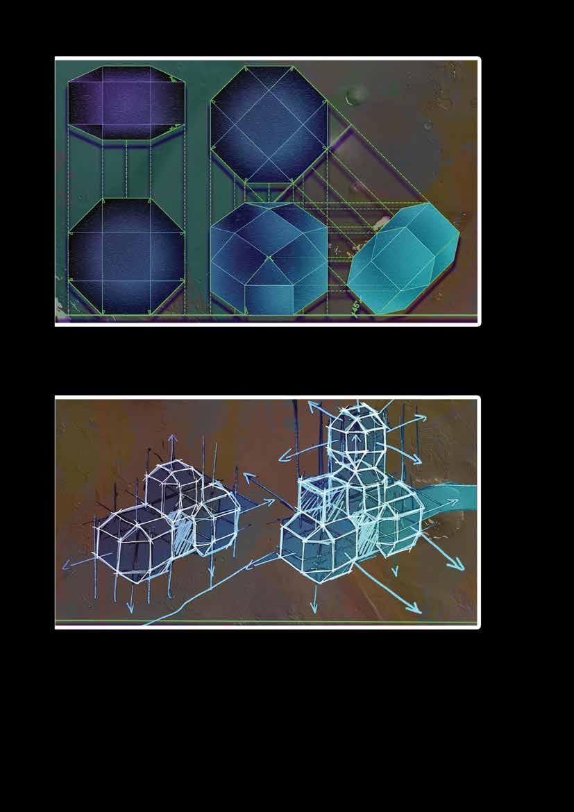
Figure 42 technical representation of Rhombicuboctahedron
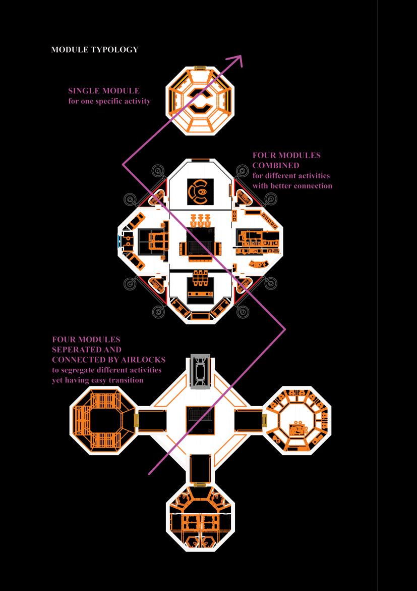
Figure 43 Concept sketch - Module connection
93
94
95
96
97
98

99
100
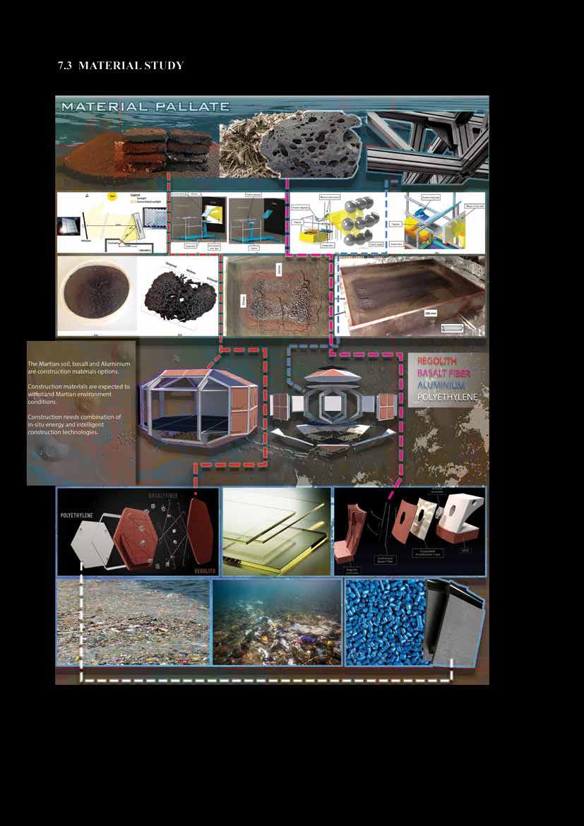
Figure 44 material study
101
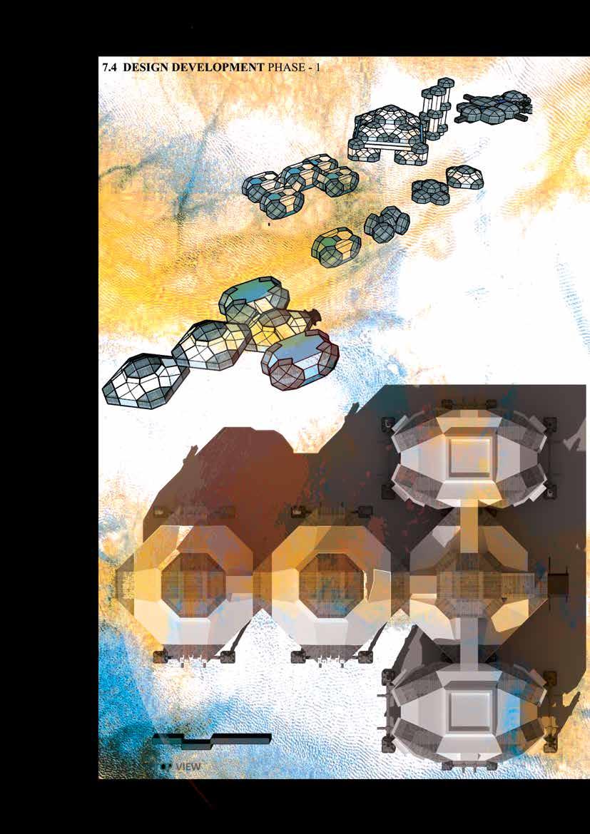
Figure 45 Concept sketch - connection typology of combined modules - DD phase 1
102
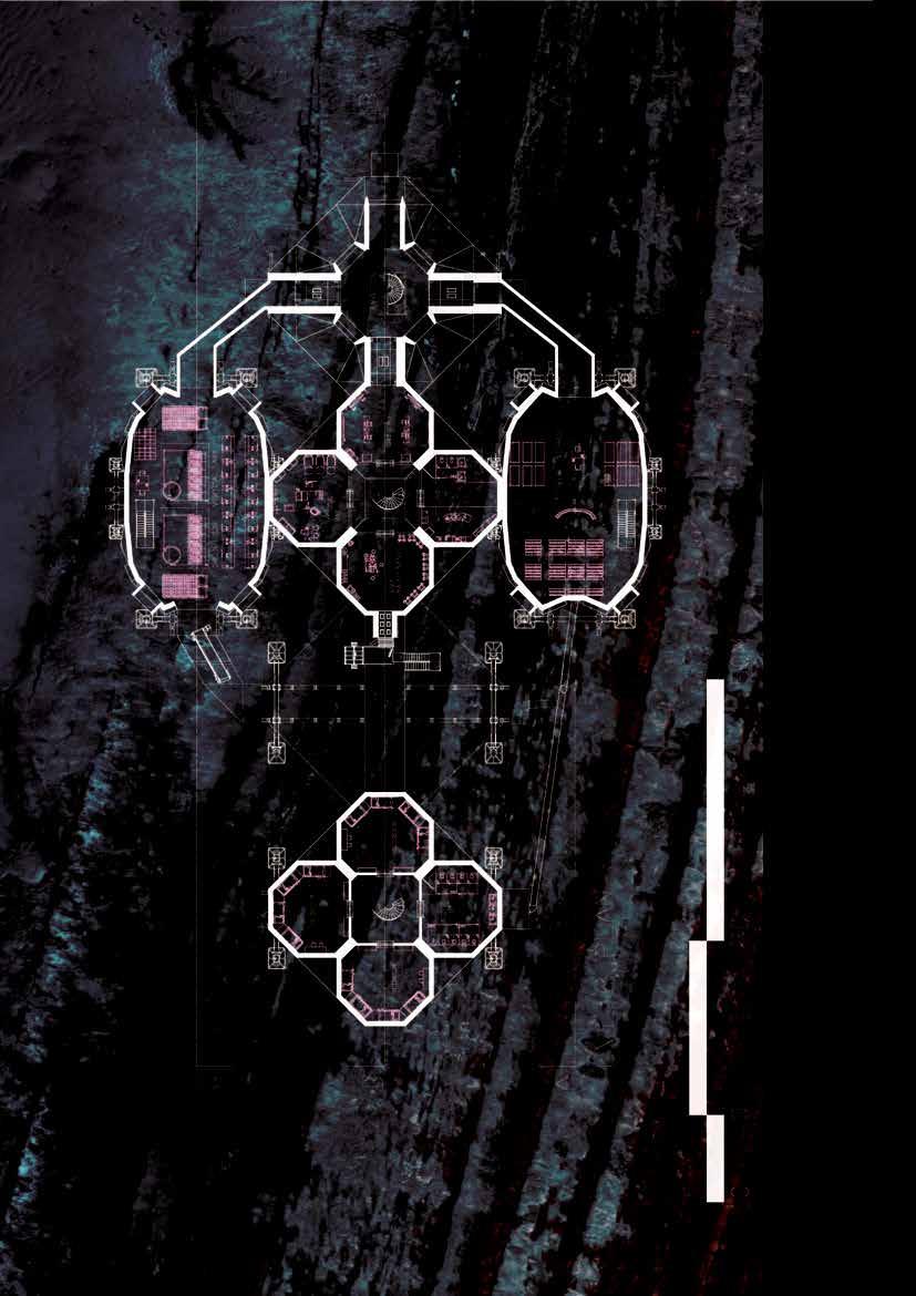
Figure 46 Level 2 plan - Phase 1
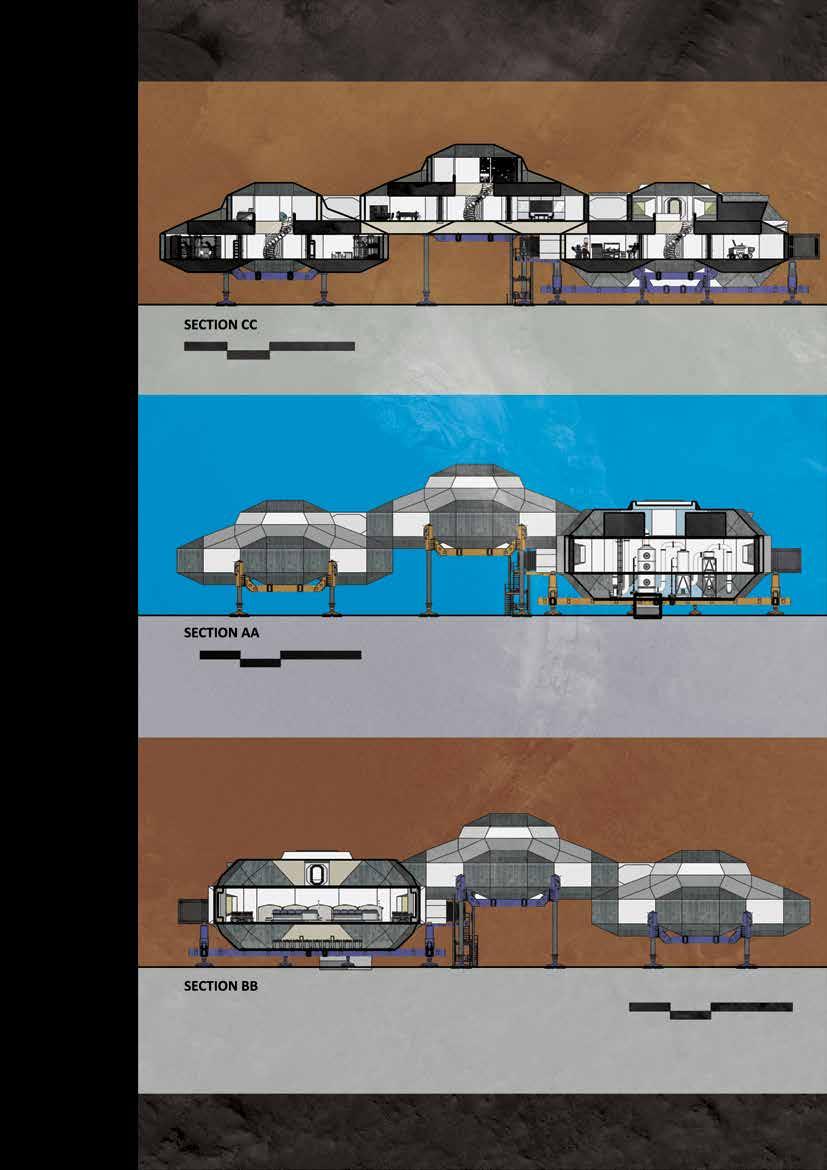
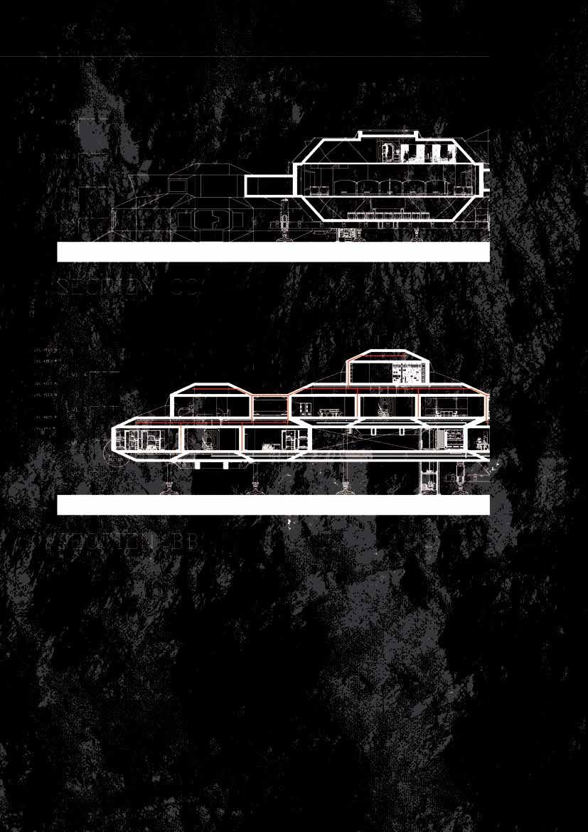
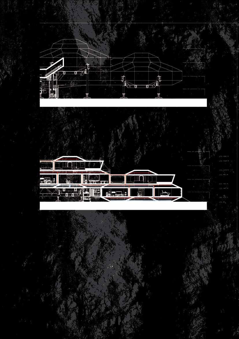
103 Figure 47 SECTIONS - DD PHASE 1
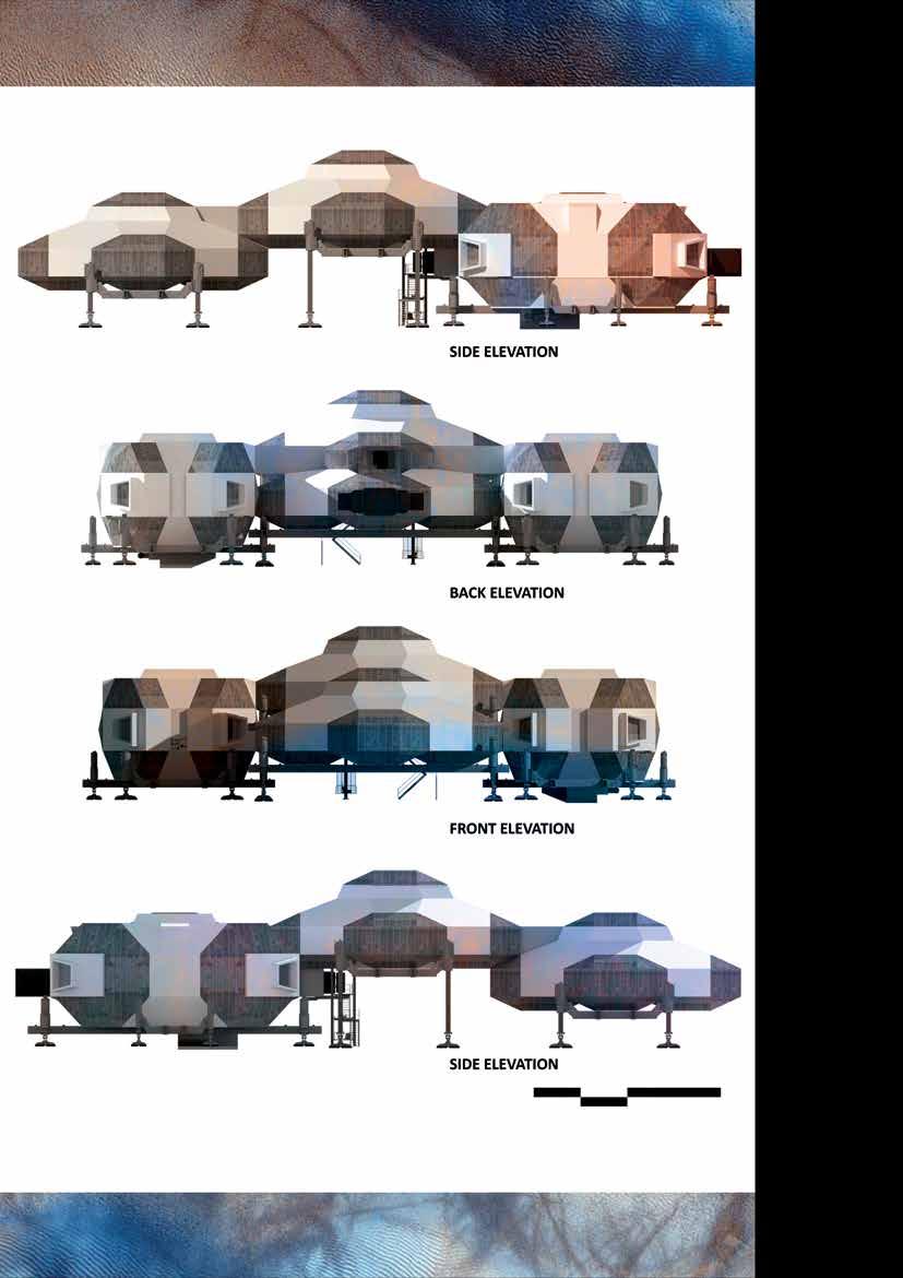
104 Figure 48 ELEVATIONS - DD PHASE 1
105
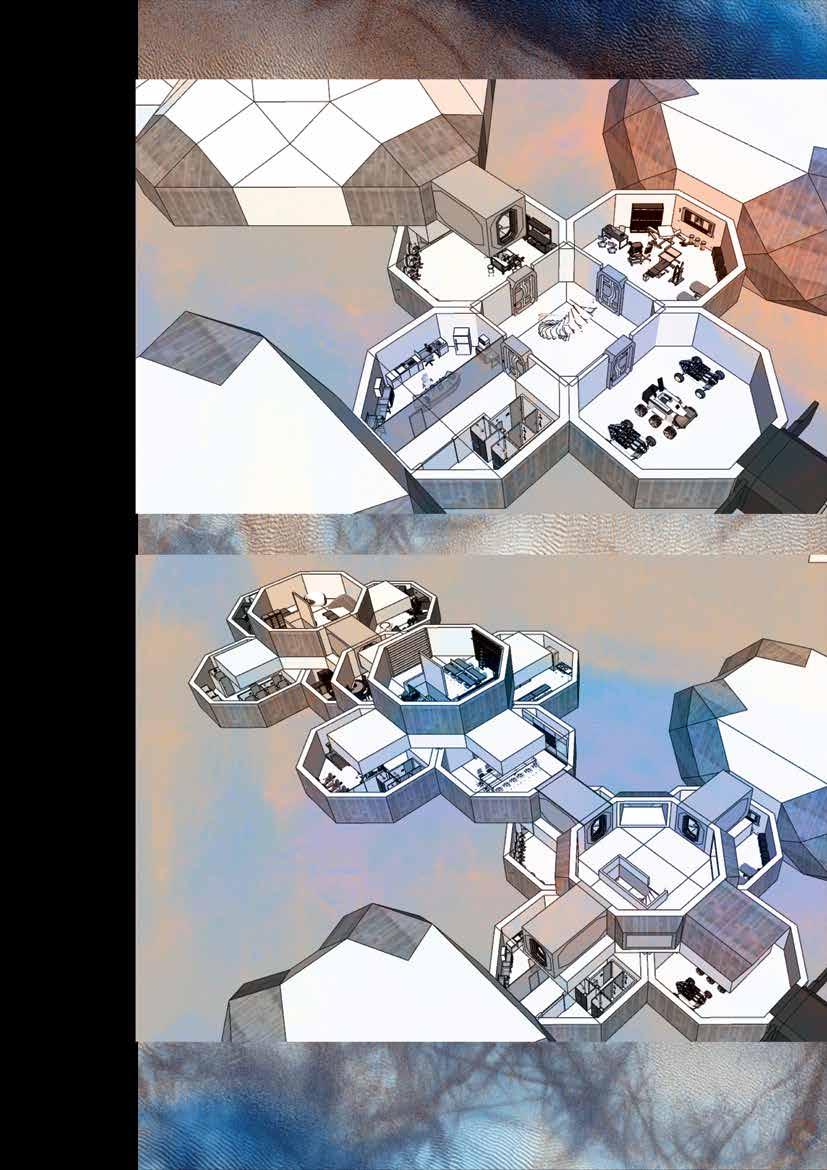
Figure 49 INTERIOR VIEWS - DD PHASE 1
Figure 51 SECTION BB’ - DD PHASE 1
Design development phase 1 - In this typology single module has been used for smaller activity containing lesser area, for the activities which require bigger space such as Greenhouse , Water extraction facility and payload - different typology of module has been design containing larger area.
106
Figure 50 SECTION CC’ - DD PHASE 1
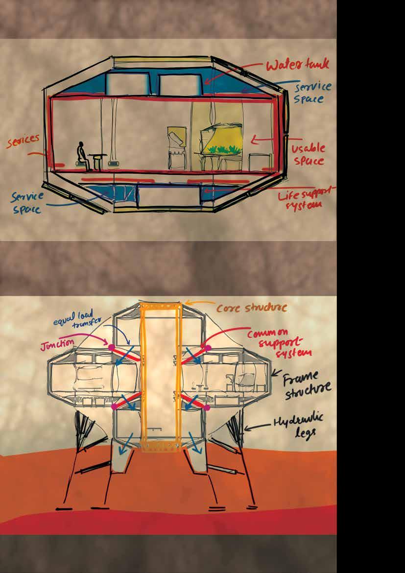
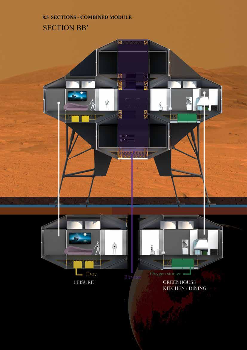
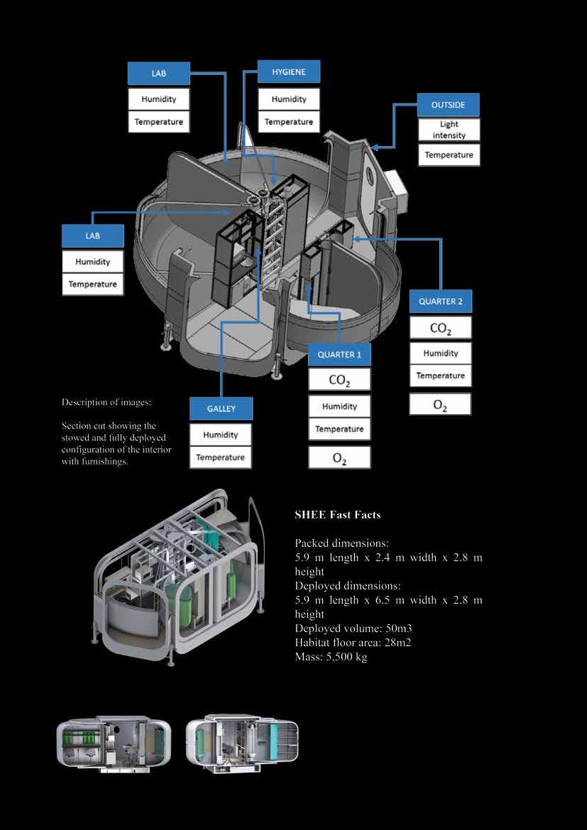
This section shows how services can be fixed in to upper and lower parts of the module, where the services can be consealed within the sufficient area where maintenance can be done easily and the space in the center of the module can be used solely for different activities for the people living inside the habitat.
107
108
109
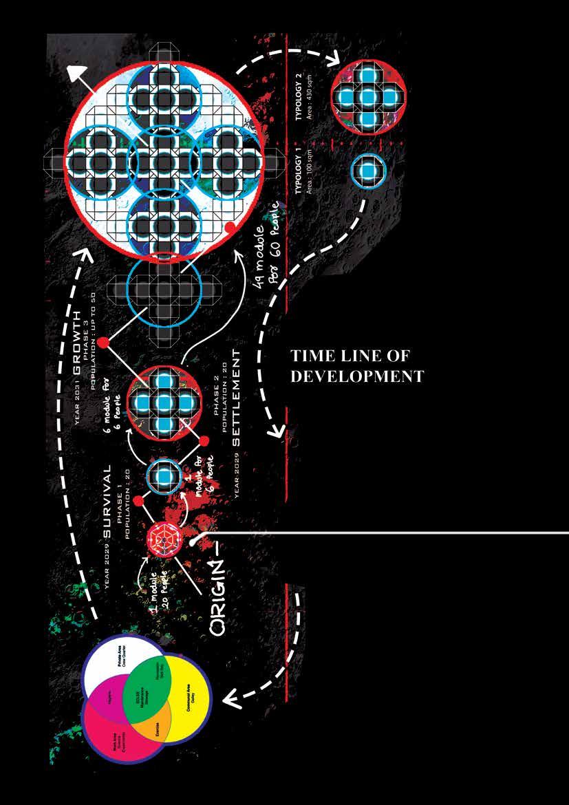
Figure 52 Timeline of Development phase 2
110
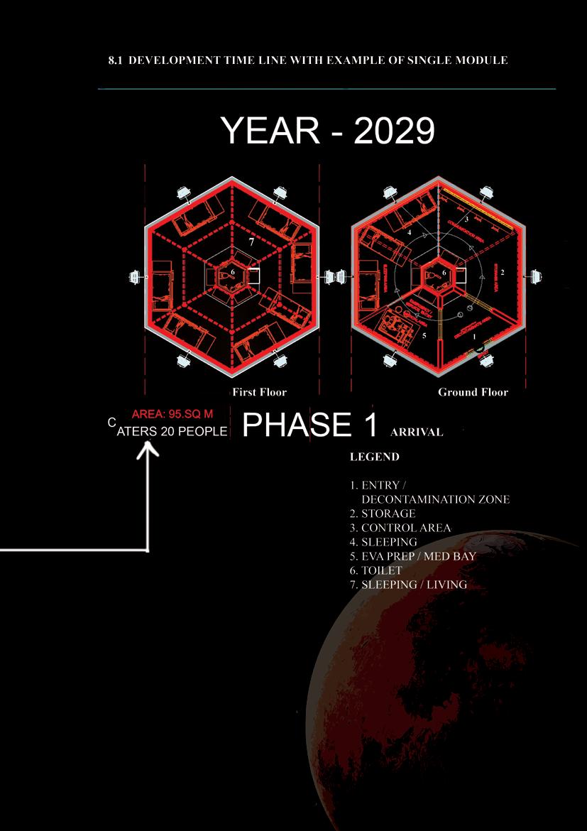
THE EARTH MODULE - This smaller hab containing 95 sqm of area will be transported from earth along with the astronauts which can be assembled by them easily after the landing is done. It is made in separate parts, which can be assembled and makes the complete habitat for living and working purpose. It can host 20 people facilitating their sleeping and working requirements. ECLSS can be fixed after the assembling is done. Earth module is made with High-Density Polyethylene, which can counter radiation from the surface and the Sun.
111
FFigure 53 Plans of Earth module
112
Figure 54 Conceptual sketch showing services configuration
Figure 55 Conceptual sketch showing load transfer of each module
113
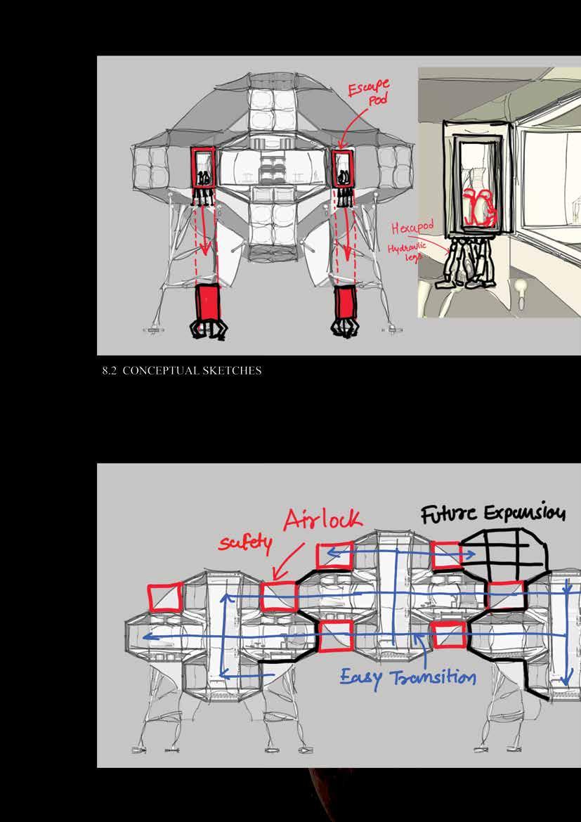
Figure 56 Conceptual sketch - Escape pod configuration
Figure 57 Conceptual sketch - connection of combined modules
114
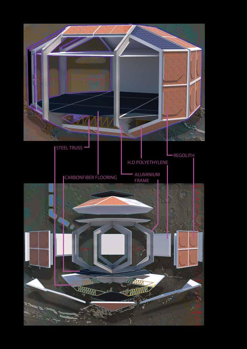
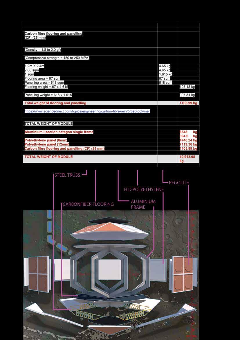
Figure 58 Exploded view of single module
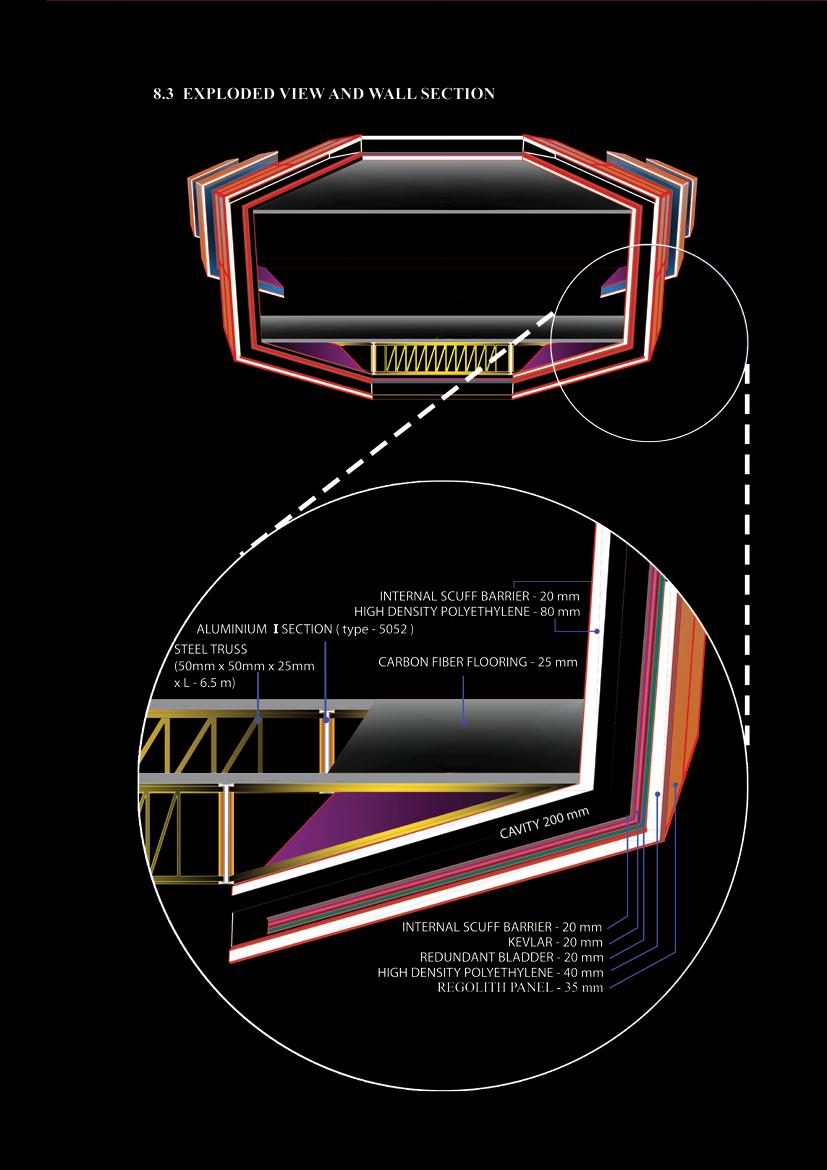
Figure 59 Wall section of single module
115
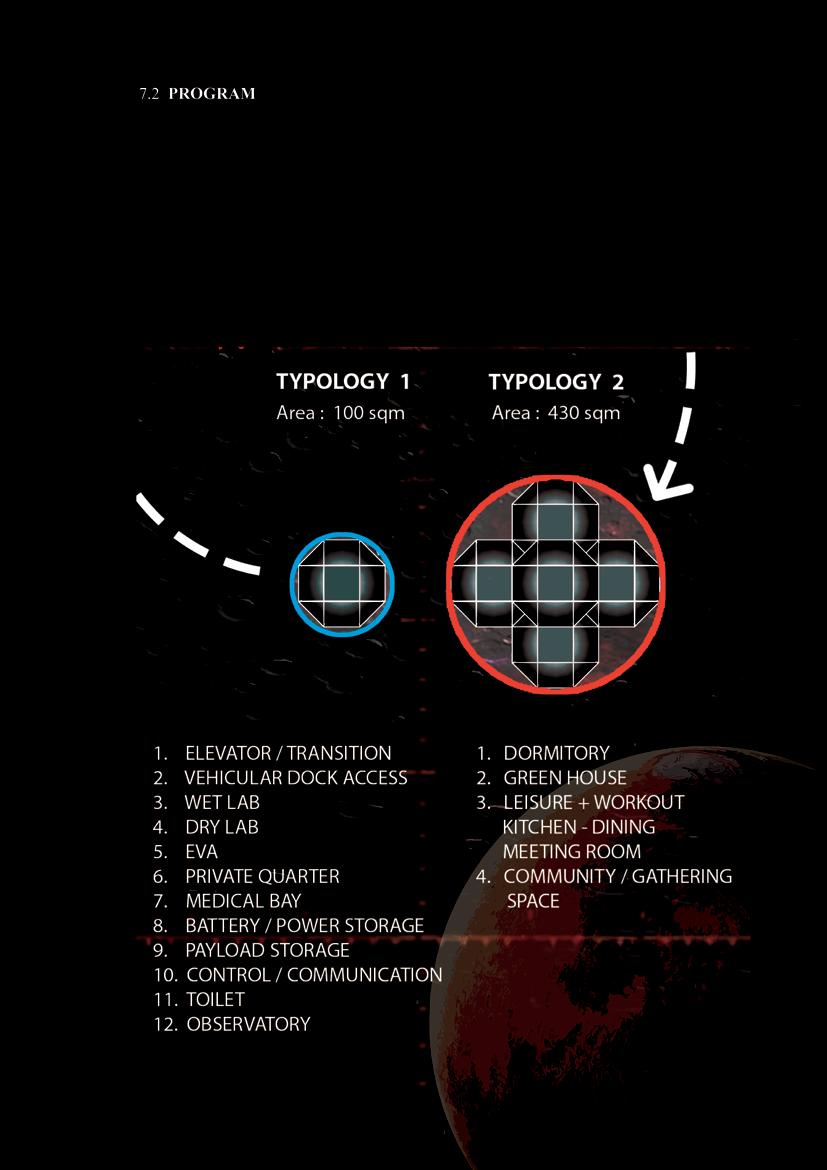
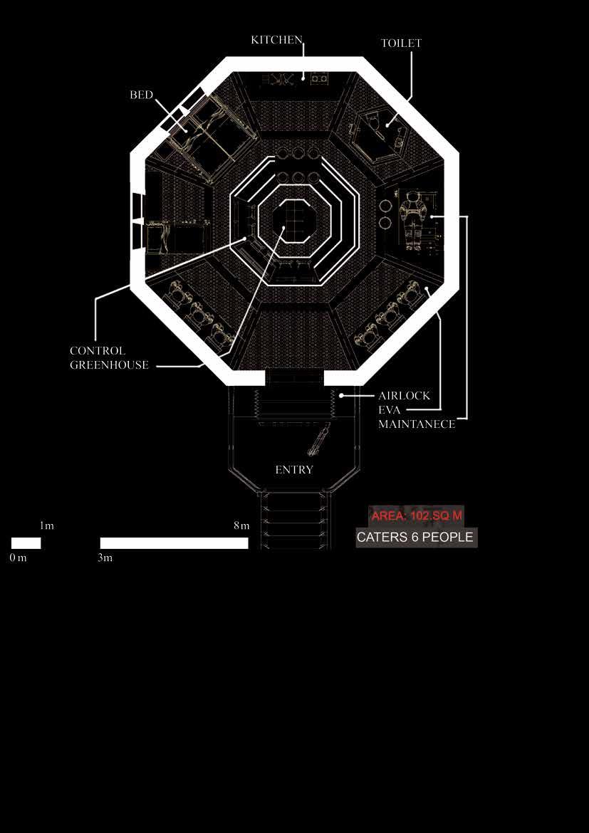
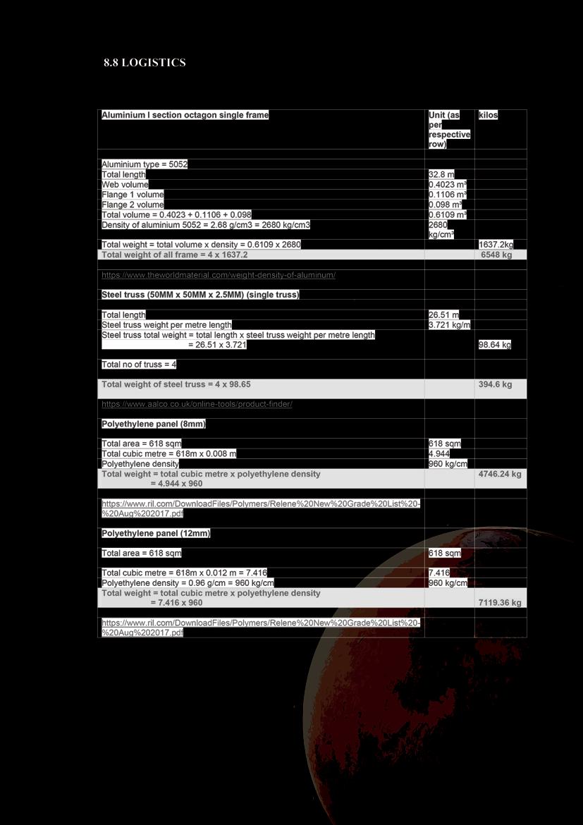
After settling in the Earth module, construction of this single module will be started. Structural elements such as Aluminium frames and inside and outside wall panels made with high-density polyethylene along with the flooring and ceiling made of carbon fiber is transported from earth along with the astronauts. After assembling the inner structure out er panels are constructed with sintered Regolith and basalt fiber rods to counter the tensile force. This module contains 100 sqm of space and can host 6 people providing them with working and sleeping reuirements.
116
Figure 60 plan of single module
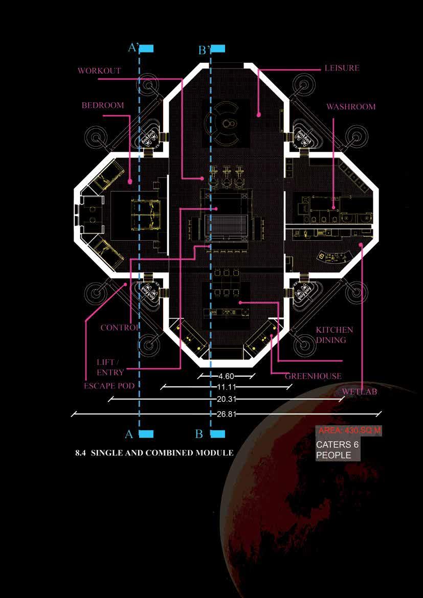
Figure 61 Plan of combined module
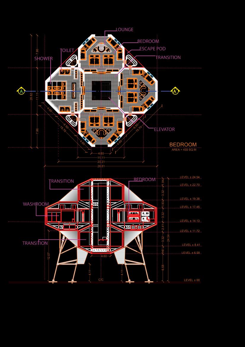
This module is a combination of six single module. As astronauts are moving into settle ment mode from survival mode this module is constructed. Combined module contains 430 sqm of area and can host six people providing them with sleeping and working require ments. In this module spaces for leisure activities, extra payload storages and elevator for easy transition are included. Bigger spaces are provided for better psychological condition of astronauts living inside.
117
118
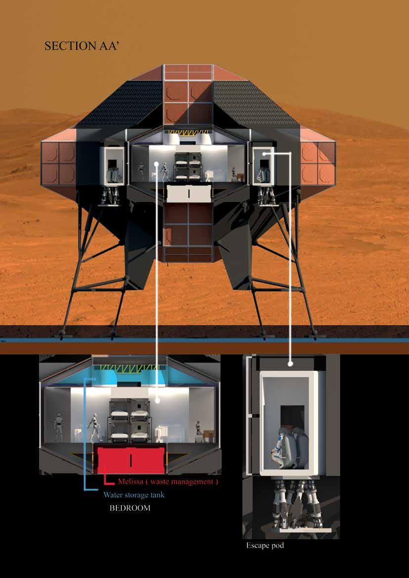
Figure 62 Section AA’ - Combined module - DD final phase
119
Figure 63 Section BB’ - Combined module - DD final phase
120
121
122
123
124
125
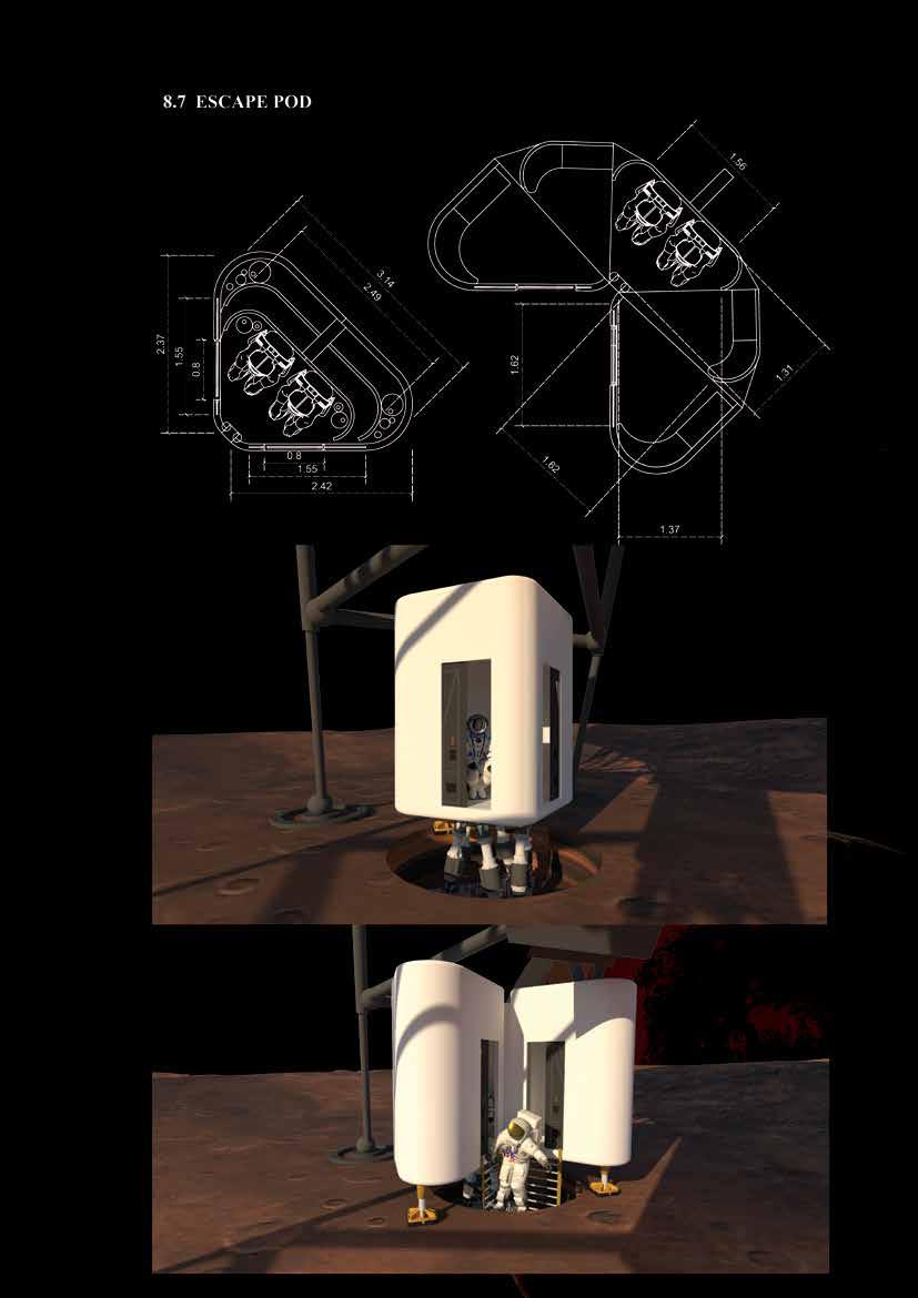
Figure 64 Escape pod - Plans - Packed and Deployed stages
Figure 65 Escape pod - 3D views - Packed and Deployed stages t v
126
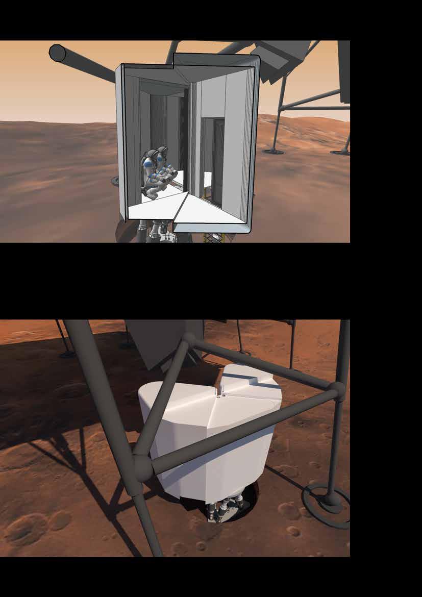
Figure 66 Escape pod - Sectional view
127
128
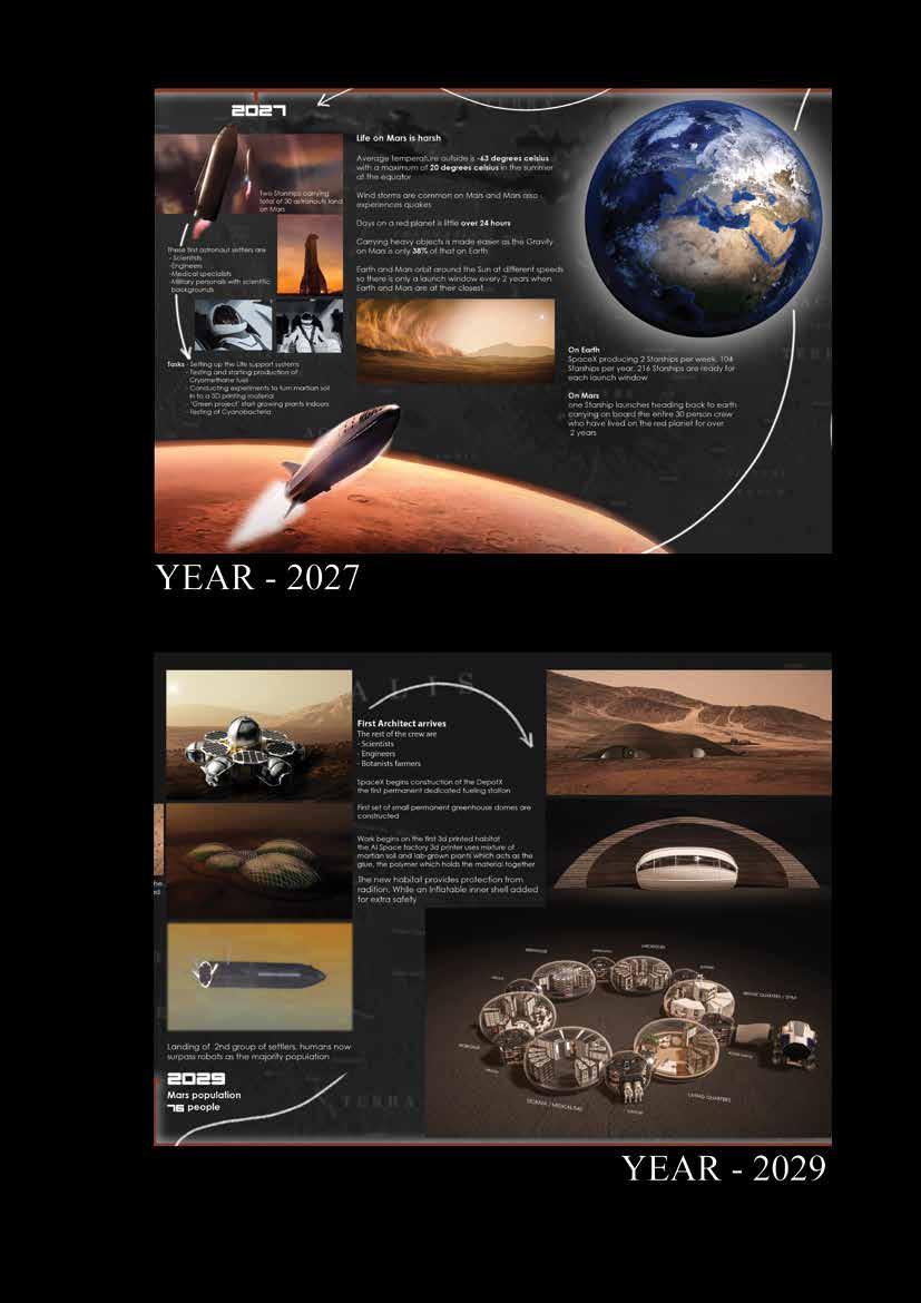
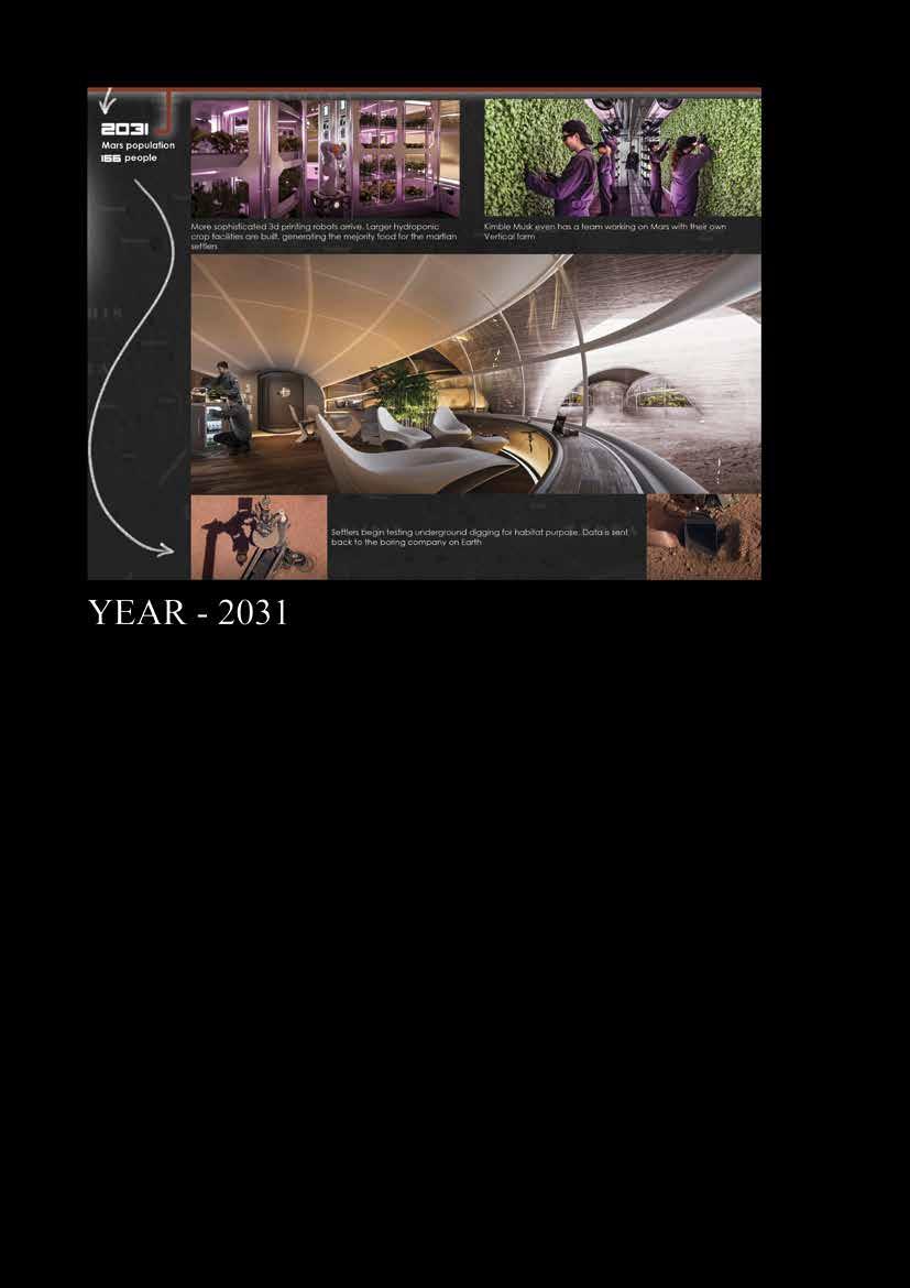
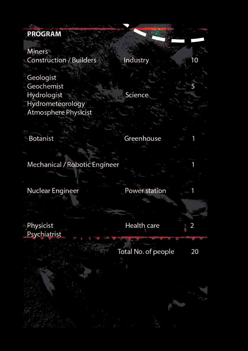
It is the year 2031. As 20 astronauts living on Mars for 2 years got in to Settlement mode from Survival mode, now 40 more people has reached to the surface of the red planet, with more construction materials and other resources imported from Earth in four Starships with the capacity of carrying 400 tons of cargo. Initially these 40 astronauts will also be living in their provided Earth modules.
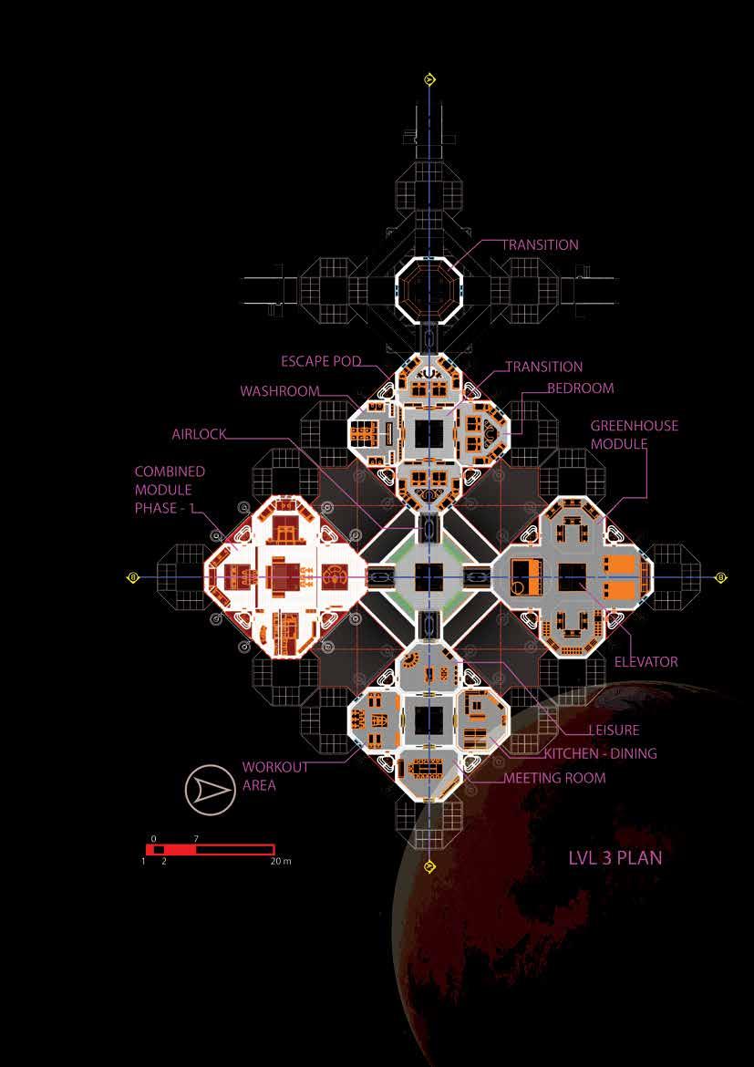
With more construction materials and resources these 40 astronauts will join the other 20 astronauts who are already living on the red planet from past two years and will begin con struction of the complete facility. Five more combined modules will be constructed and will be attached to the older combined module. In these five combined modules interior plan ning is done with respect to the number of people is increased. And the facility is planned according to the living and working schedule of the total of 60 people living most of the time inside the Habitat.
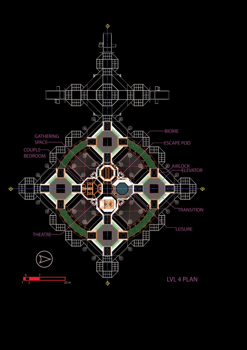
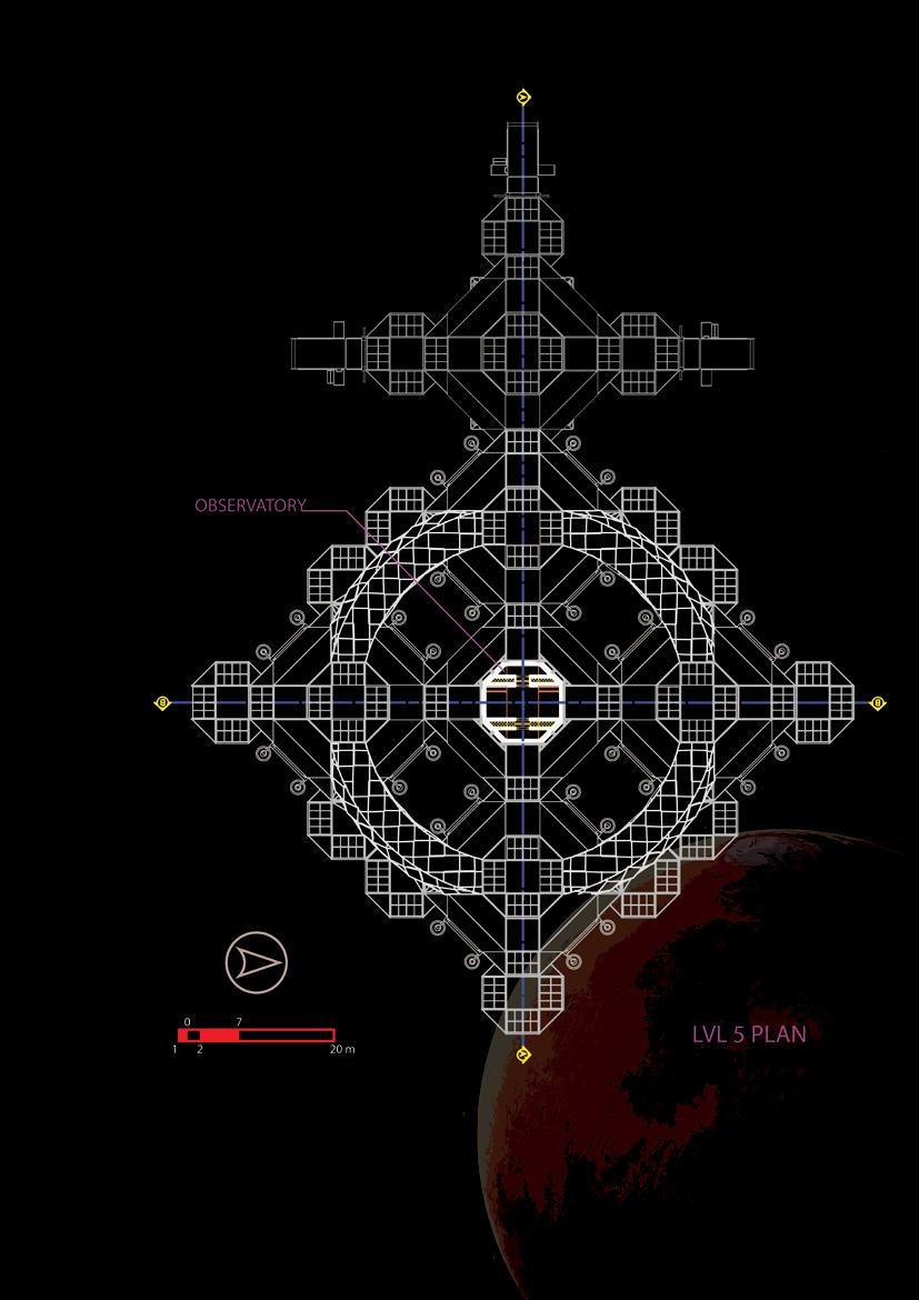
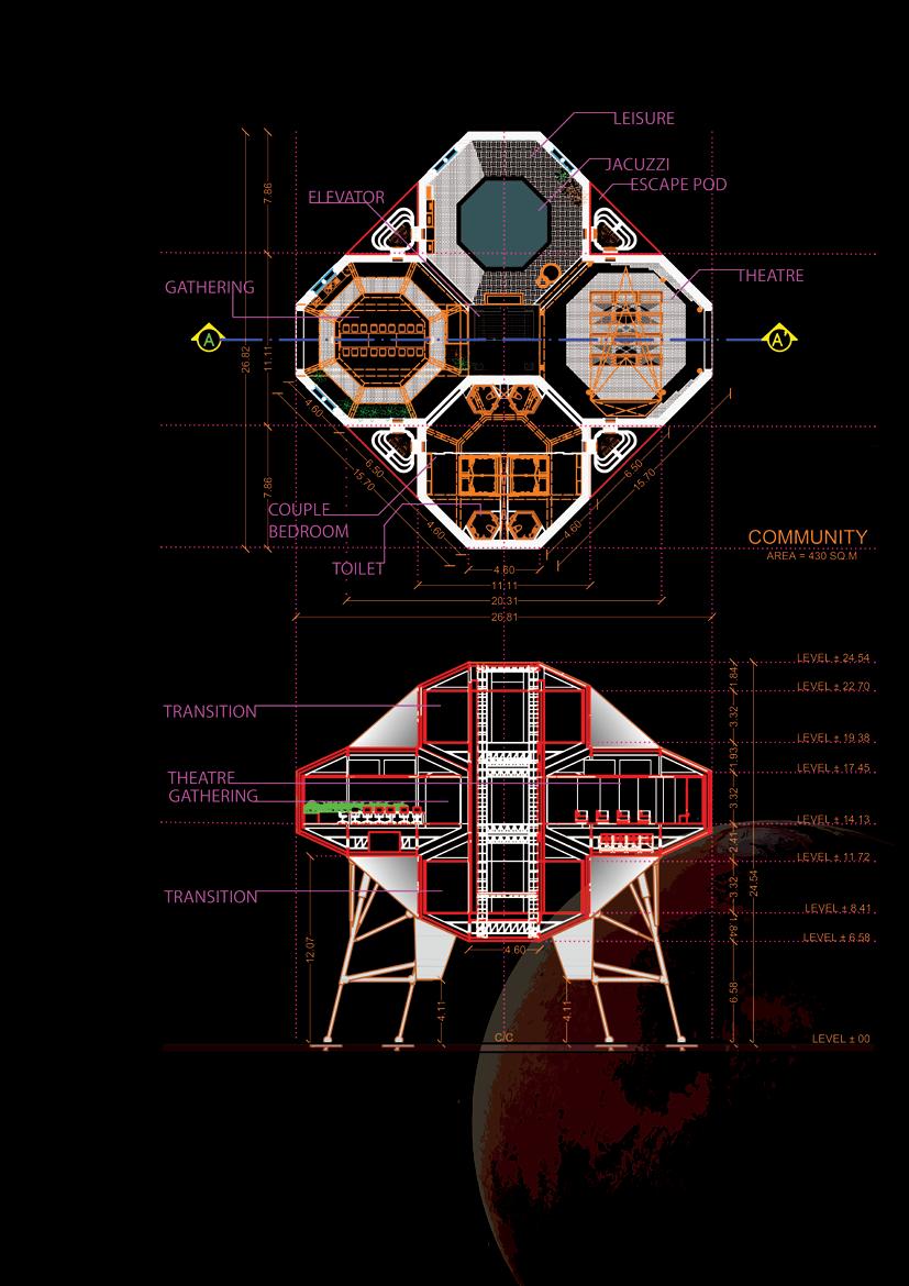
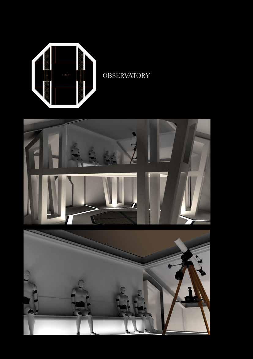
60 People are equivalent to a smaller community, hence bigger community spaces and rec reational spaces are provided so the psychological conditions and the living quality of the astronauts can be improved and they can proceed into GROWTH mode from the settle ment mode. As the smaller community is built, there are chances that from that 60 people, couples will be formed and would want to live together after the working hours, hence the provision of a Couple Bedroom with attached washroom is given at every level of the habi tat. Every combined module is connected by the Airlocks for safety purposes and each com bined module has its own ECLSS and Water storage, so in the time of any emergency, if one module is compromised, the other modules can be detached and saved. To keep astronauts in a better psychological state, On the upper module, provision of Observatory and Biomes are given so astronauts can have good earthly feeling while walking into those biomes and can look to their first home Earth from the observatory provided.
129
130
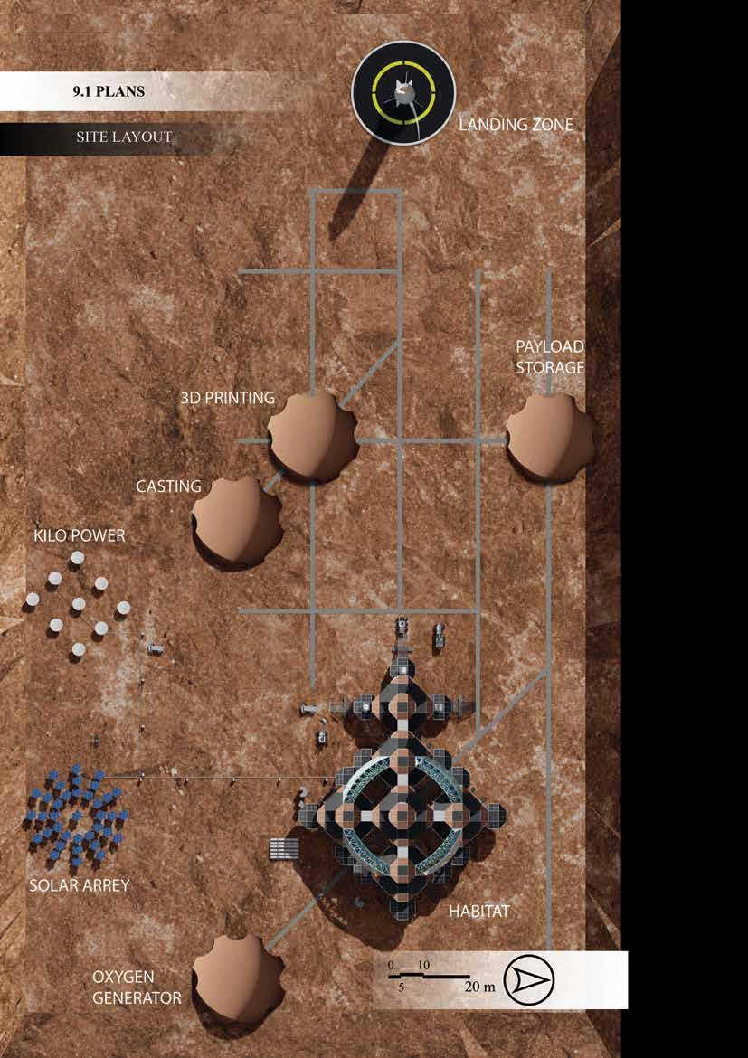
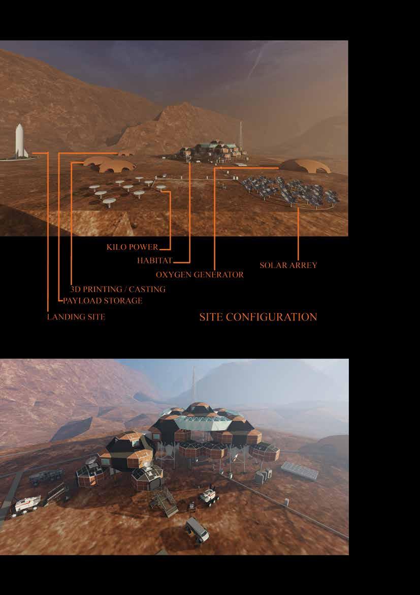
Figure 67 Site Layout v
131
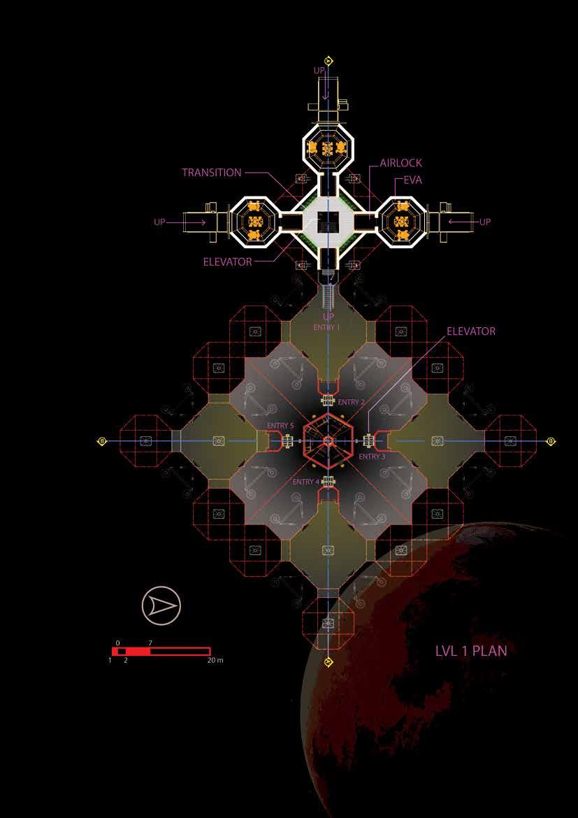
Figure 68 Level 1 plan Figure 68 Level 1 plan
Figure 69 Level 2 plan
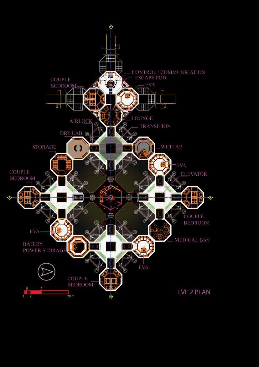
132
Figure 70 Level 3 plan
133
Figure 71 Level 4 plan
134
Figure 72 Level 5 plan
135
136
Figure 73 Roof plan
Figure 77 Combined module - Plan - section 1
140
9.4
COMBINED MODULE INDIVIDUAL PLAN - SECTION
Figure 78 Combined module - plan-Section 2
141
Figure 79 Combined module - plan - section 3
142
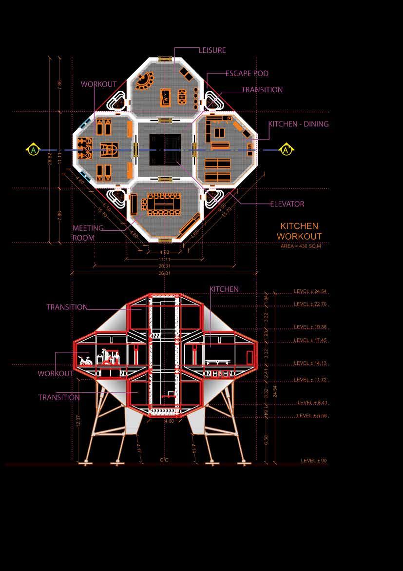
Figure 80 Combined module - Plan - Section 4
143
Figure 81 Single module sections
144
9.5
SINGLE MODULE - SECTION
145
9.6
Figure 81 Single module sections
146
9.7
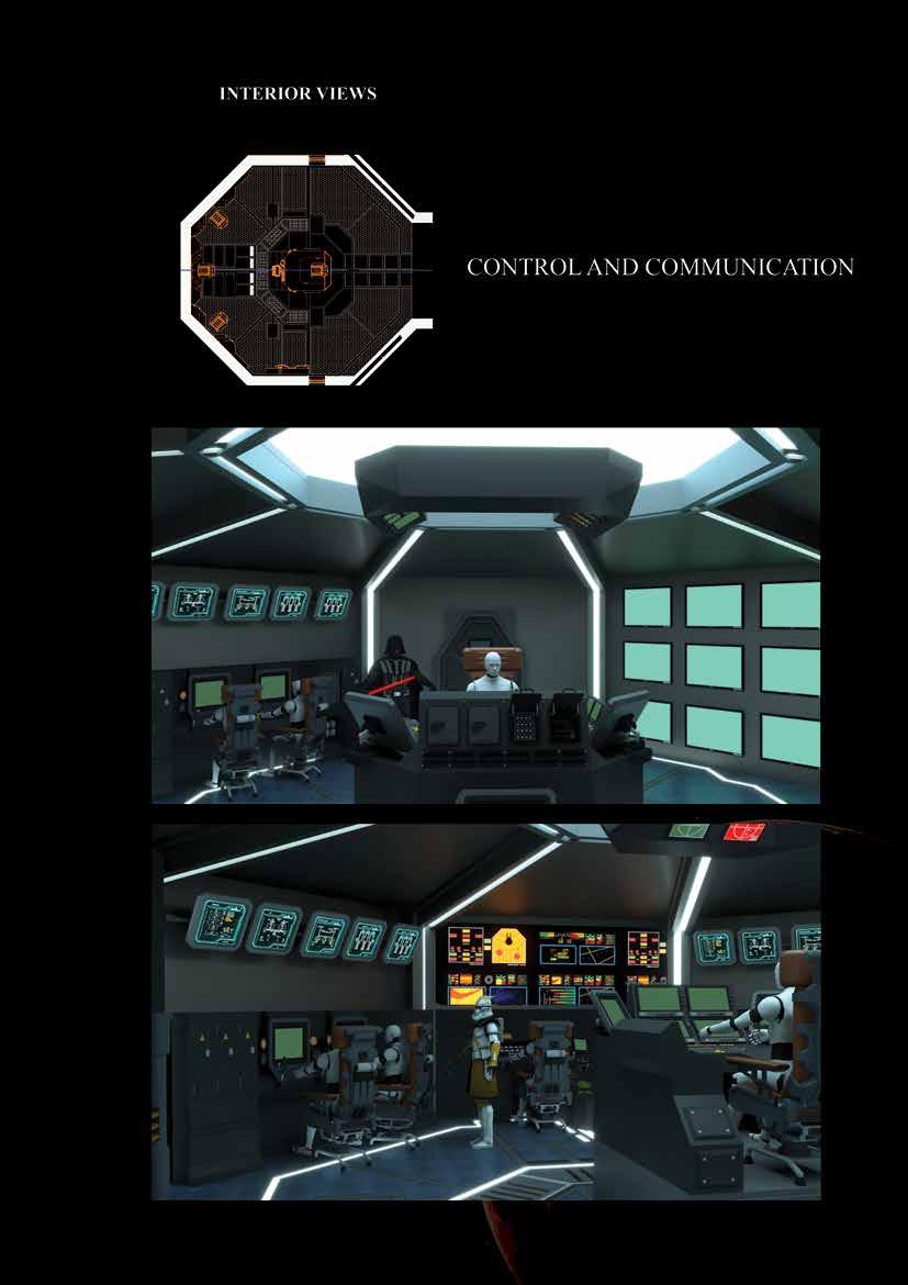
Figure 83 Interior View - Control and Communication
147
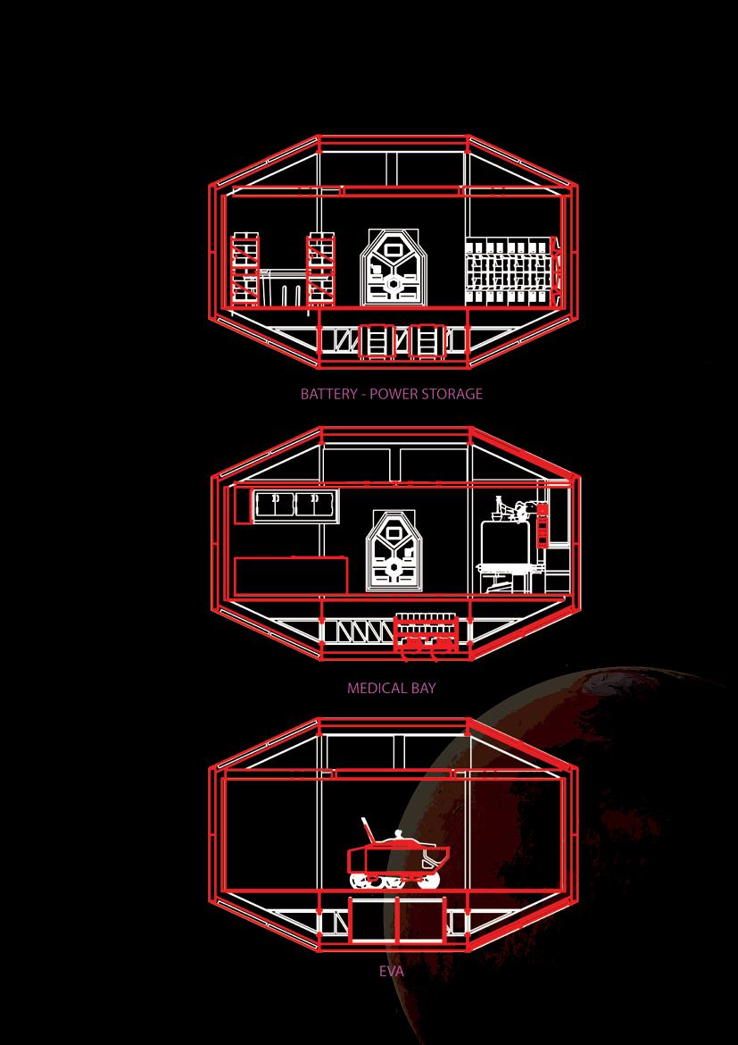
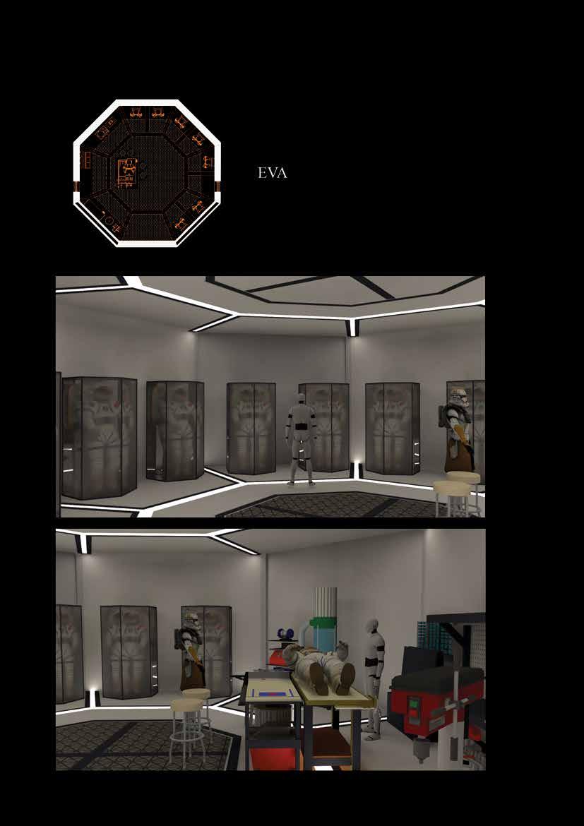
Figure 84 Interior View - EVA
148
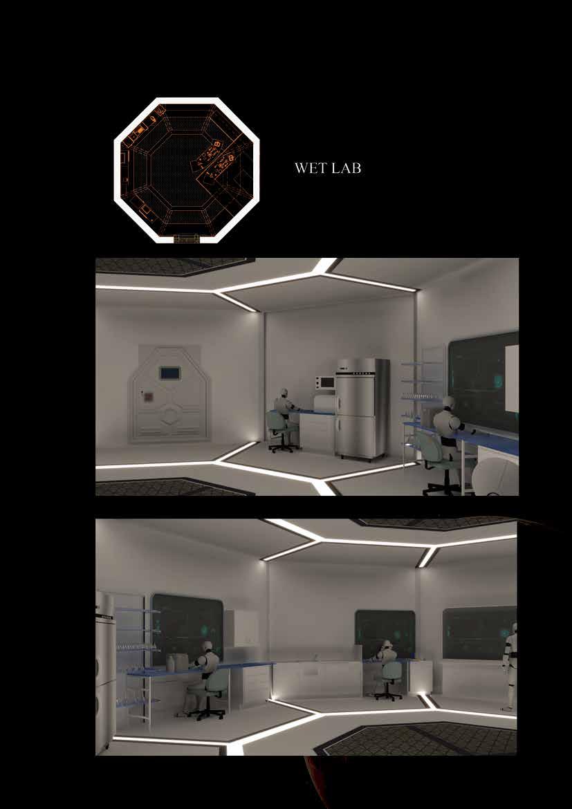
Figure 85 Interior View - WETLAB
149
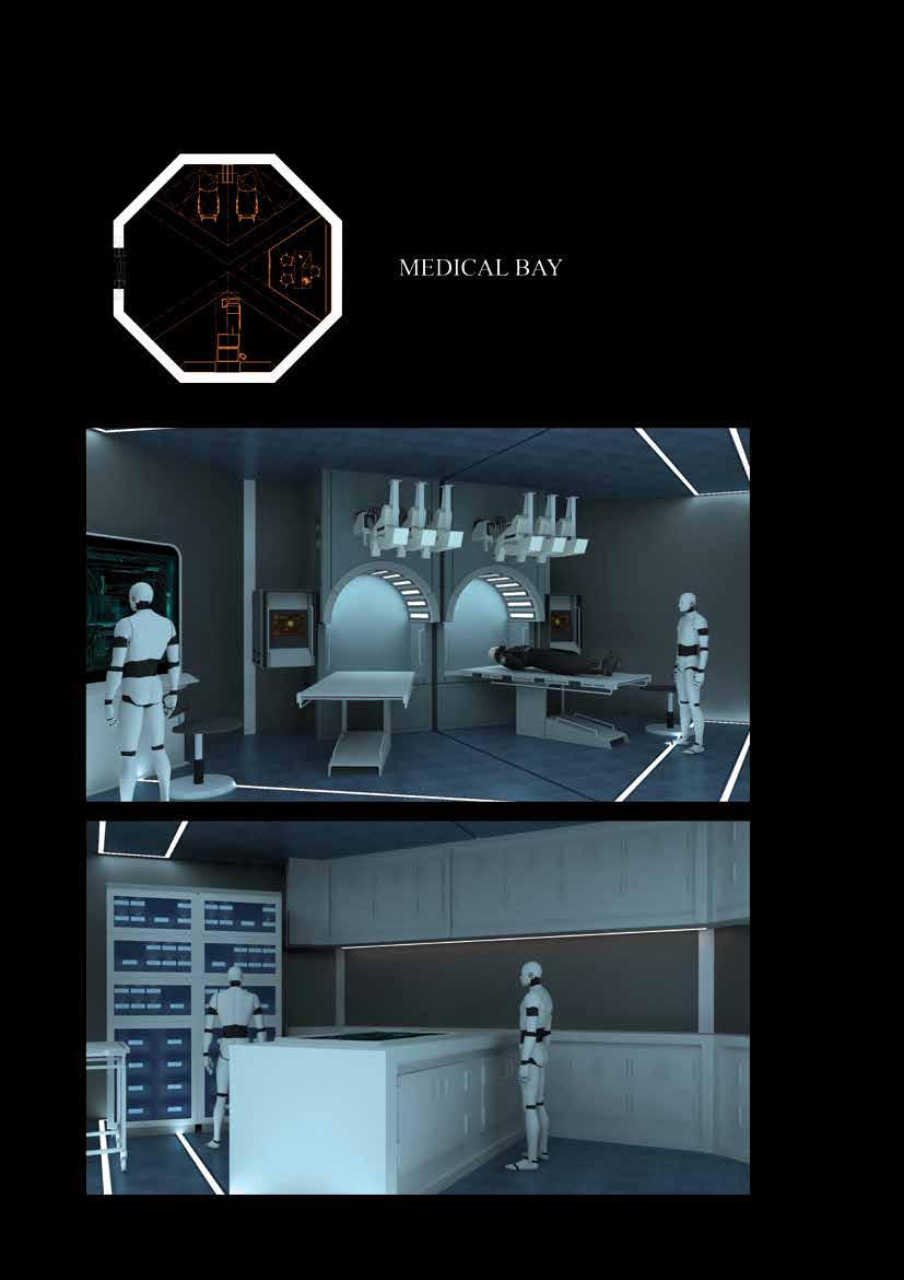
Figure 86 Interior View - MEDICAL BAY
150
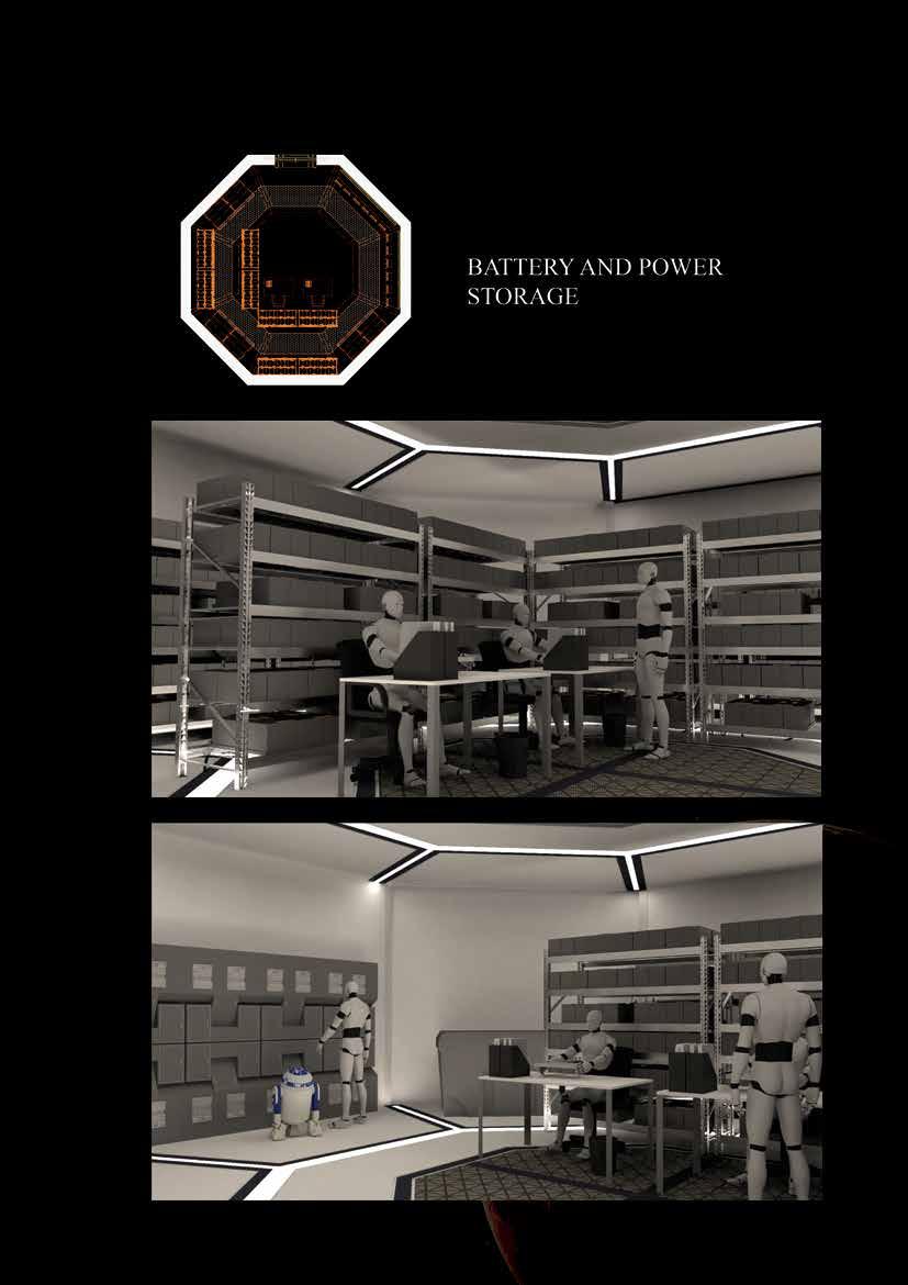
Figure 87 interior view - BATTERY AND POWER STOR AGE
151
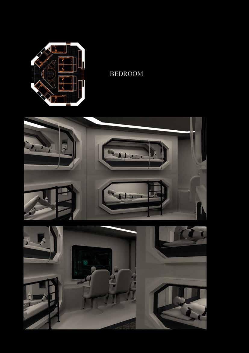
Figure 88 Interior view - BEDROOM

152
Figure 89 Interior view - GREENHOUSE
153
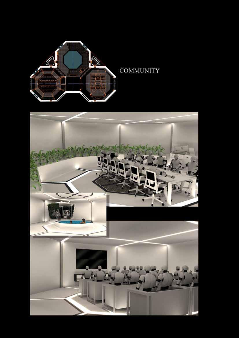
Figure 90 Interior view - COMMUNITY
154
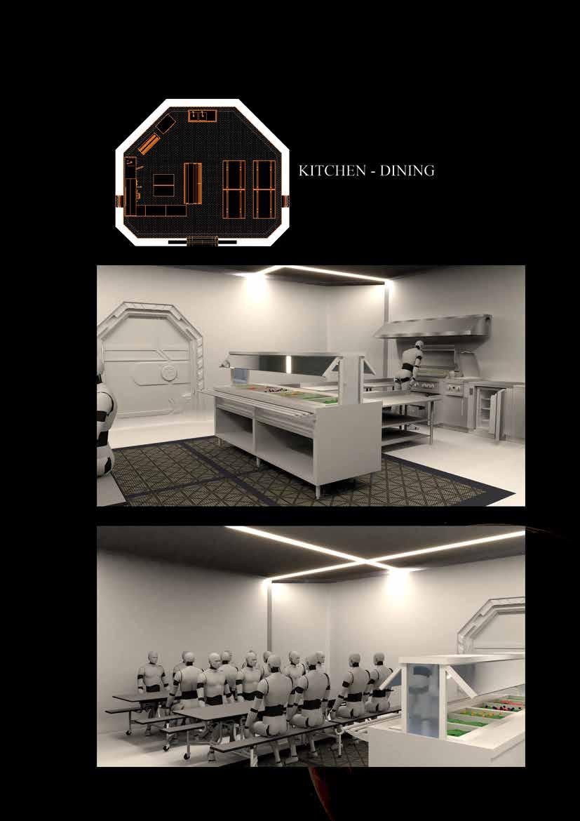
Figure 91 Interior view – KITCHEN-DINING
155
Figure 88 Interior view - BEDROOM
156 9.8
157
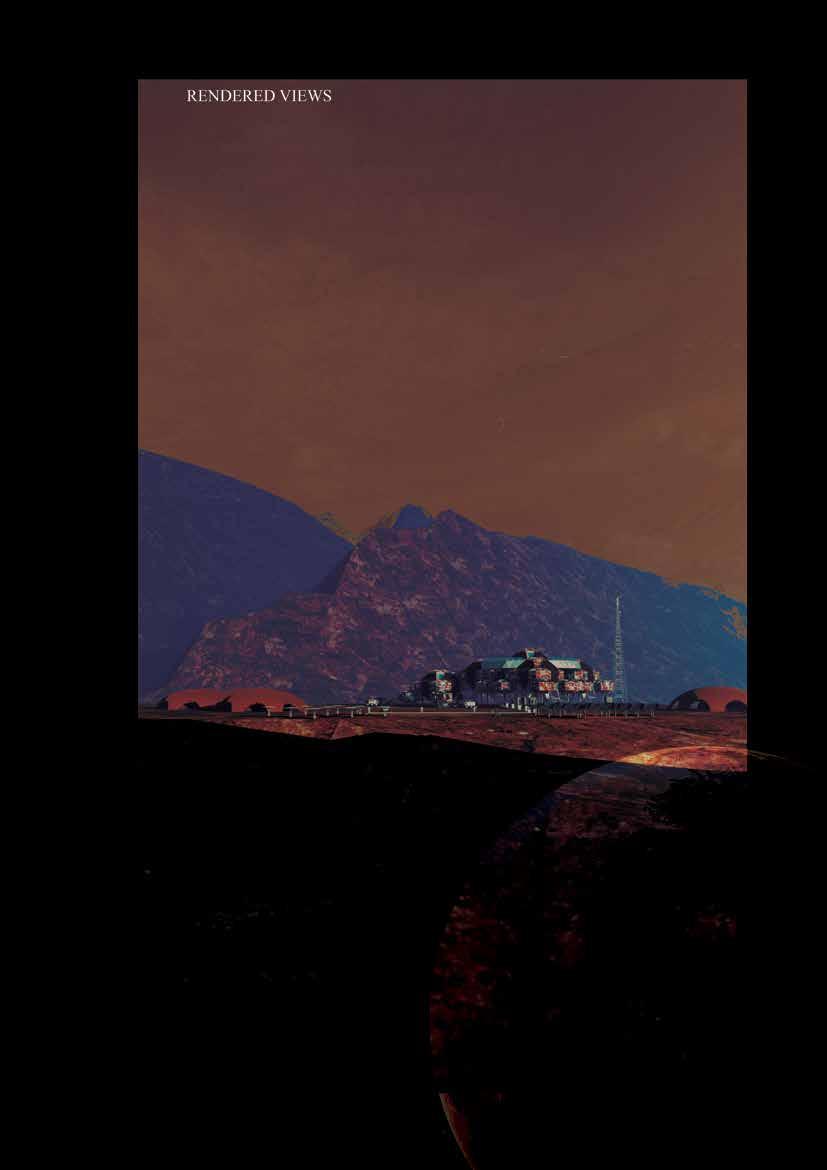
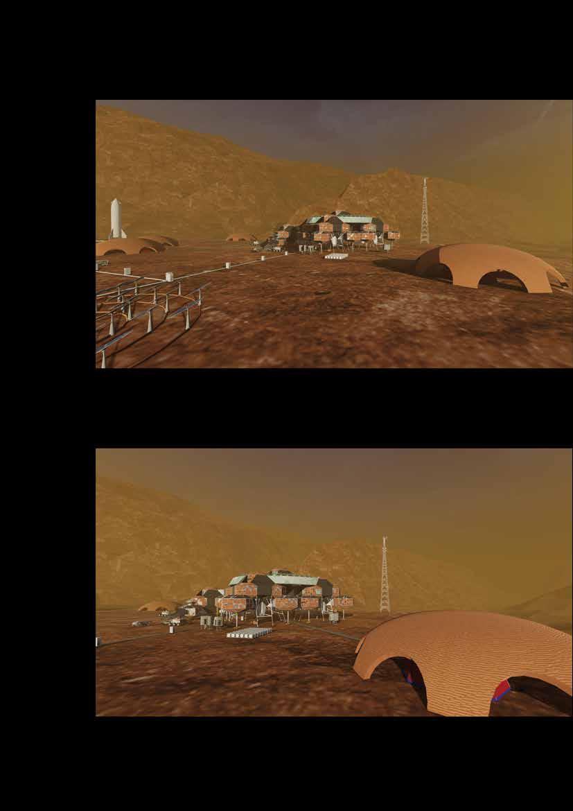
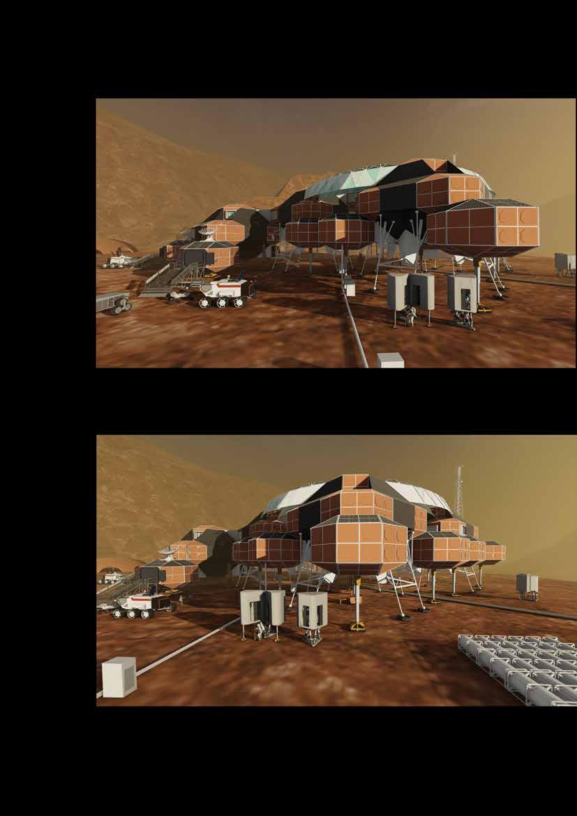
Figure 93 Exterior view - SITE LAYOUT
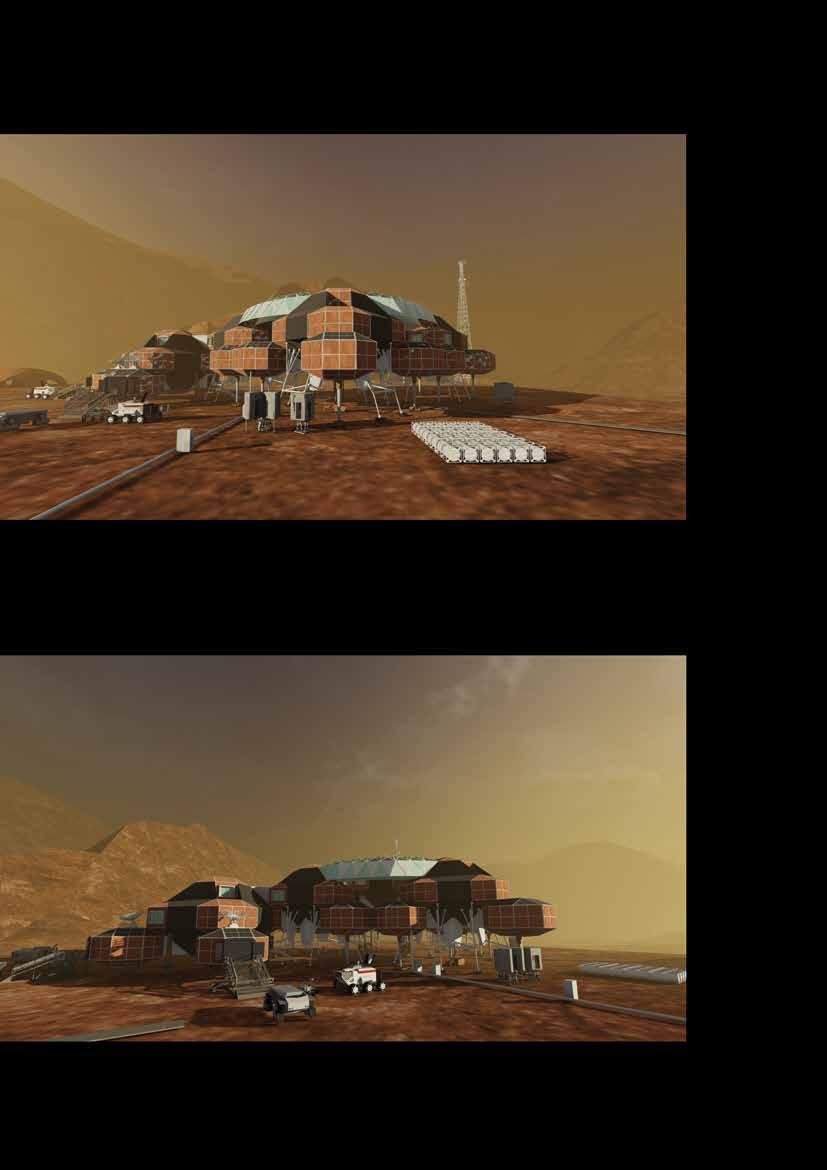
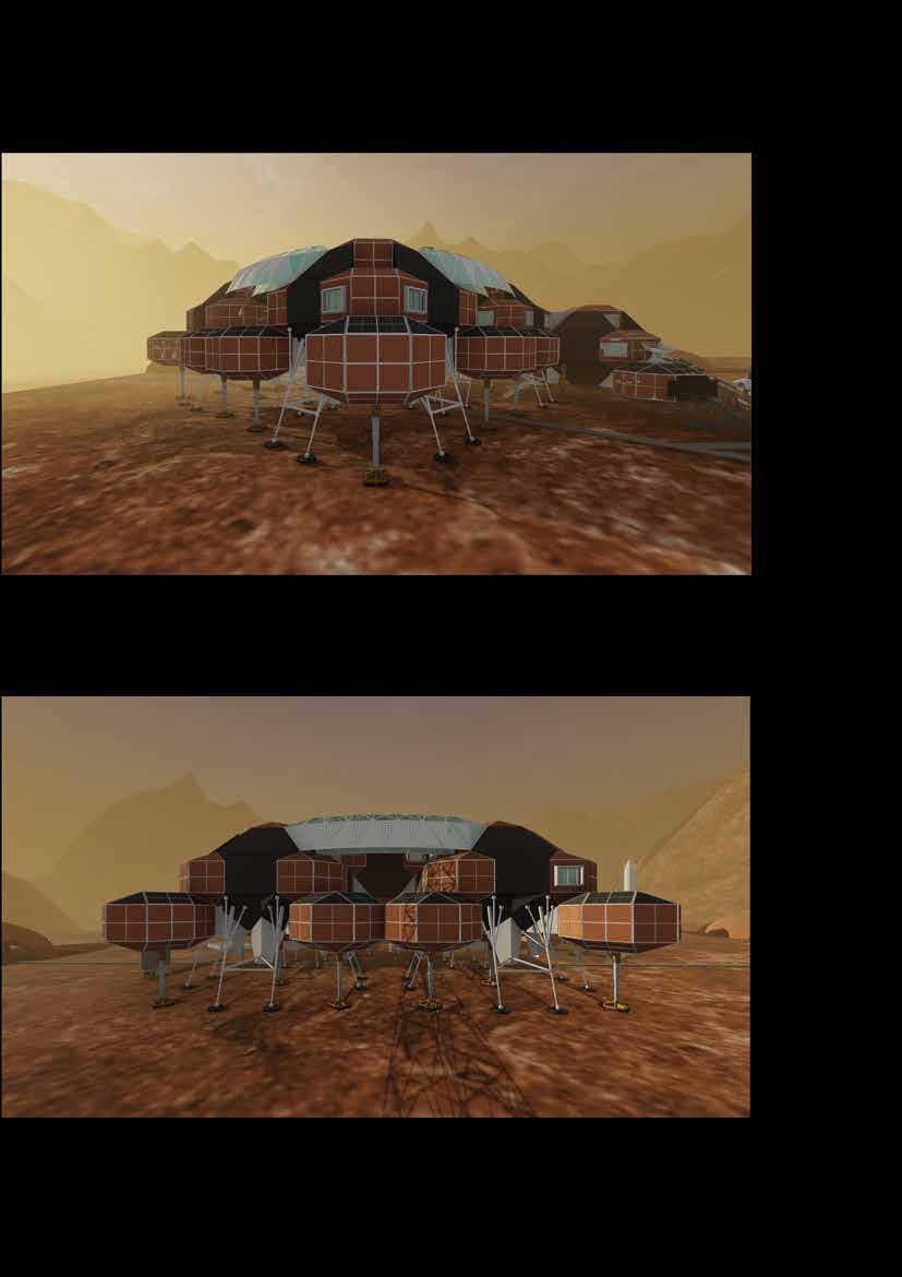
Figure 94 Exterior view - HABITAT
158
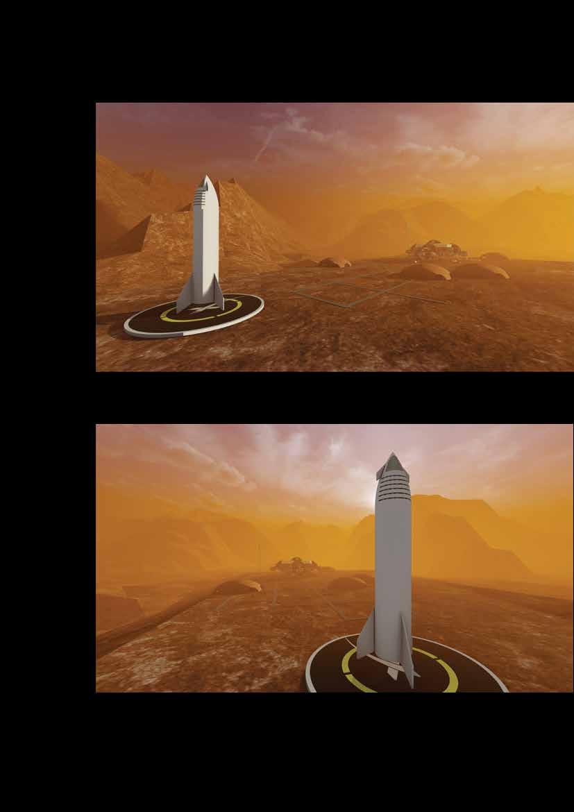
Figure 95 Exterior view - LANDING SITE
159
Figure 96 Exterior view - 3D PRINTING - CASTING
160
Figure 97 Exterior view - KILOPOWER
161
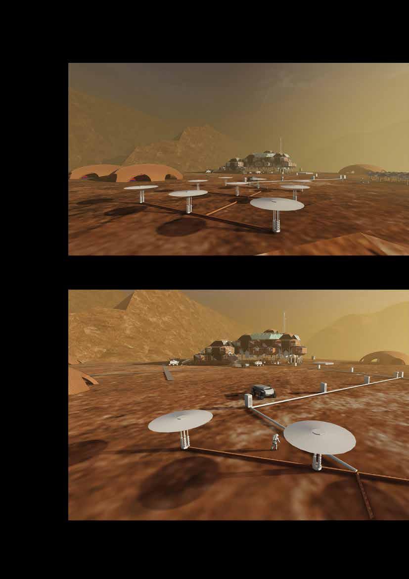
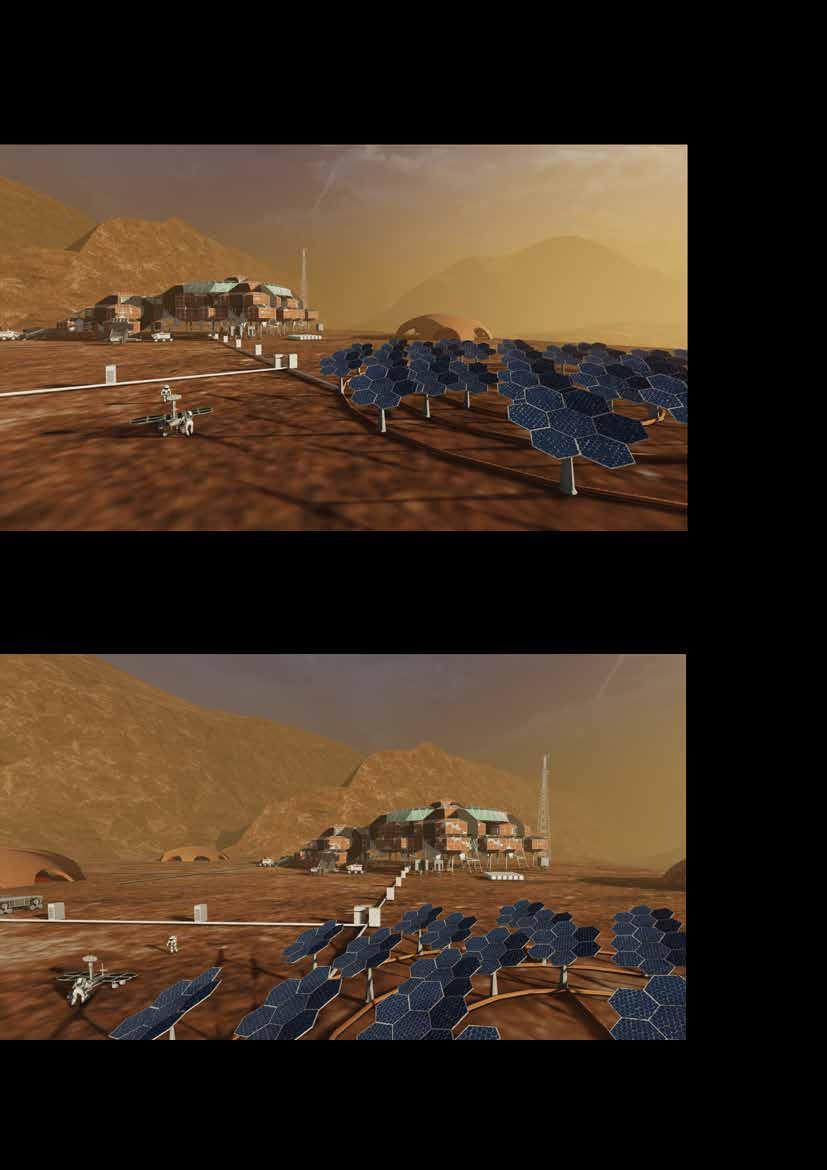
Figure 98 Exterior view – SOLAR ARREY
162
Figure 99 Exterior view – OXYGEN GENERATION FACILITY
163
Figure 100 Exterior view – ESCAPE POD
164
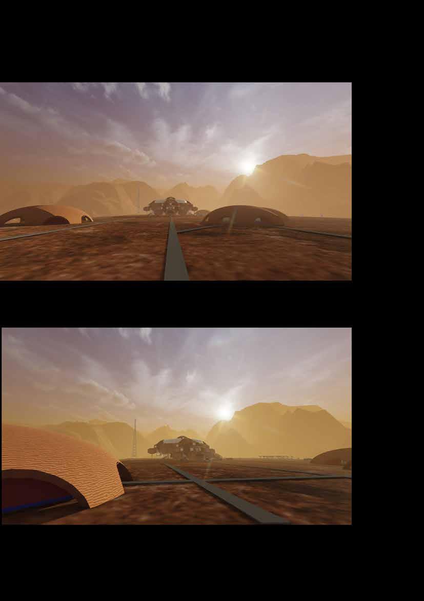
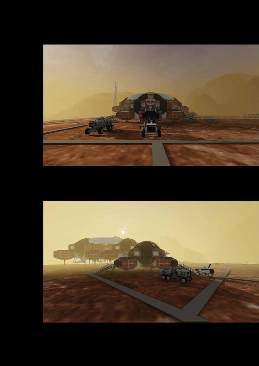
Figure 101 Exterior view – VEHICULAR DOCK
165
Figure 102 Exterior view – BIOMES
166
Figure 103 Exterior view – ESCAPE POD - VEHICULAR DOCK
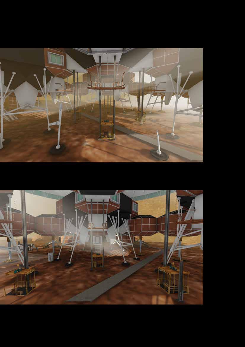
167
Figure 104 Exterior view – ENTRY TO HABITAT
168
Page No. 169
170
171
172
173
170